EP1517393A2 - Methods and apparatus for assembling solid oxide fuel cells - Google Patents
Methods and apparatus for assembling solid oxide fuel cells Download PDFInfo
- Publication number
- EP1517393A2 EP1517393A2 EP04255641A EP04255641A EP1517393A2 EP 1517393 A2 EP1517393 A2 EP 1517393A2 EP 04255641 A EP04255641 A EP 04255641A EP 04255641 A EP04255641 A EP 04255641A EP 1517393 A2 EP1517393 A2 EP 1517393A2
- Authority
- EP
- European Patent Office
- Prior art keywords
- fuel cell
- fuel
- cell stack
- isolation device
- stack assembly
- Prior art date
- Legal status (The legal status is an assumption and is not a legal conclusion. Google has not performed a legal analysis and makes no representation as to the accuracy of the status listed.)
- Withdrawn
Links
Images


Classifications
-
- H—ELECTRICITY
- H01—ELECTRIC ELEMENTS
- H01M—PROCESSES OR MEANS, e.g. BATTERIES, FOR THE DIRECT CONVERSION OF CHEMICAL ENERGY INTO ELECTRICAL ENERGY
- H01M8/00—Fuel cells; Manufacture thereof
- H01M8/02—Details
- H01M8/0271—Sealing or supporting means around electrodes, matrices or membranes
- H01M8/0273—Sealing or supporting means around electrodes, matrices or membranes with sealing or supporting means in the form of a frame
-
- H—ELECTRICITY
- H01—ELECTRIC ELEMENTS
- H01M—PROCESSES OR MEANS, e.g. BATTERIES, FOR THE DIRECT CONVERSION OF CHEMICAL ENERGY INTO ELECTRICAL ENERGY
- H01M8/00—Fuel cells; Manufacture thereof
- H01M8/04—Auxiliary arrangements, e.g. for control of pressure or for circulation of fluids
- H01M8/04223—Auxiliary arrangements, e.g. for control of pressure or for circulation of fluids during start-up or shut-down; Depolarisation or activation, e.g. purging; Means for short-circuiting defective fuel cells
- H01M8/04246—Short circuiting means for defective fuel cells
-
- H—ELECTRICITY
- H01—ELECTRIC ELEMENTS
- H01M—PROCESSES OR MEANS, e.g. BATTERIES, FOR THE DIRECT CONVERSION OF CHEMICAL ENERGY INTO ELECTRICAL ENERGY
- H01M8/00—Fuel cells; Manufacture thereof
- H01M8/24—Grouping of fuel cells, e.g. stacking of fuel cells
- H01M8/241—Grouping of fuel cells, e.g. stacking of fuel cells with solid or matrix-supported electrolytes
- H01M8/2425—High-temperature cells with solid electrolytes
- H01M8/2432—Grouping of unit cells of planar configuration
-
- H—ELECTRICITY
- H01—ELECTRIC ELEMENTS
- H01M—PROCESSES OR MEANS, e.g. BATTERIES, FOR THE DIRECT CONVERSION OF CHEMICAL ENERGY INTO ELECTRICAL ENERGY
- H01M8/00—Fuel cells; Manufacture thereof
- H01M8/24—Grouping of fuel cells, e.g. stacking of fuel cells
- H01M8/2465—Details of groupings of fuel cells
- H01M8/2483—Details of groupings of fuel cells characterised by internal manifolds
-
- Y—GENERAL TAGGING OF NEW TECHNOLOGICAL DEVELOPMENTS; GENERAL TAGGING OF CROSS-SECTIONAL TECHNOLOGIES SPANNING OVER SEVERAL SECTIONS OF THE IPC; TECHNICAL SUBJECTS COVERED BY FORMER USPC CROSS-REFERENCE ART COLLECTIONS [XRACs] AND DIGESTS
- Y02—TECHNOLOGIES OR APPLICATIONS FOR MITIGATION OR ADAPTATION AGAINST CLIMATE CHANGE
- Y02E—REDUCTION OF GREENHOUSE GAS [GHG] EMISSIONS, RELATED TO ENERGY GENERATION, TRANSMISSION OR DISTRIBUTION
- Y02E60/00—Enabling technologies; Technologies with a potential or indirect contribution to GHG emissions mitigation
- Y02E60/30—Hydrogen technology
- Y02E60/50—Fuel cells
Definitions
- This invention relates generally to power generation, and more specifically, to methods and apparatus for assembling solid oxide fuel cells.
- a fuel cell is an electrochemical device that converts chemical energy produced by a reaction directly into electrical energy.
- Known fuel cells typically include an anode, also known as a fuel electrode, a cathode, also known as an oxidant electrode, and an electrolyte.
- Such fuel cells are electrochemical devices, similar to batteries, which react fuel and oxidant to produce electricity.
- fuel such as hydrogen and oxidant such as air are supplied continuously to the fuel cell such that it continues to produce power so long as such reactants are provided.
- a fuel cell produces electricity by catalyzing fuel and oxidant into ionized atomic hydrogen and oxygen at, respectively, the anode and cathode.
- the electrons removed from hydrogen in the ionization process at the anode are conducted to the cathode where they ionize the oxygen.
- the oxygen ions are conducted through the electrolyte where they combine with ionized hydrogen to form water as a waste product and complete the process.
- the electrolyte is otherwise impermeable to both fuel and oxidant and merely conducts oxygen ions.
- This series of electrochemical reactions is the sole means of generating electric power within the fuel cell. It is therefore desirable to reduce or eliminate any mixing of the reactants, as such mixing would result in a different combination such as combustion which produces no electric power and therefore reduces the efficiency of the fuel cell.
- Individual fuel cells produce power at low voltage, typically less than about 1 Volt per cell.
- the cells are therefore typically assembled in electrical series in a fuel cell stack to produce power at useful voltages.
- an interconnecting member is used to connect the adjacent fuel cells together in electrical series.
- fuel flows at a substantially equal flow rate to each of the fuel cells.
- the failure of a single fuel cell may cause the failure of the entire fuel stack.
- At least some known fuel stacks include a plurality of valves which are magnetically actuated from external to the cell to restrict fuel flow to the failed cell.
- actuating such valves will limit fuel flow to affected cells without isolating them electrically from the other cells, and as such, may severely limit the continued operation of the fuel cell stack.
- a conductor is inserted within the failed fuel cell to short-circuit the cell such that the fuel cell stack may be operable with the remaining fuel cells.
- the fuel cell stack can not be operated during the insertion of the conductor.
- returning the stack to a safe working and operating temperature may shorten the useful life of the stack due to thermal cycling damage.
- a fuel cell stack assembly in one aspect of the present invention, includes at least a first fuel cell and a second fuel cell electrically coupled together such that at least one sealed passage extends between the first and second fuel cells.
- Each of the fuel cells includes at least one hollow manifold that includes a wall extending between a first end and a second end. Each wall defines a chamber therein, and includes at least one opening extending therethrough in flow communication with the chamber.
- the fuel cell stack assembly also includes at least one fuel cell isolation device coupled in flow communication with each fuel cell hollow manifold. The at least one fuel cell isolation device is variably positionable during fuel cell stack assembly operation for selectively stopping fluid flow through at least one of the fuel cells.
- a fuel cell stack coupled in flow communication to an air source and a fuel source.
- the fuel cell stack includes at least three fuel cells coupled together in flow communication such that at least one sealed passage extends between the at least three fuel cells, and a plurality of interconnects that electrically couple the at least three fuel cells together such that at least one interconnect extends between each adjacent pair of fuel cells.
- the fuel cell stack also includes at least one fuel cell isolation device coupled in flow communication with each of the at least three fuel cells. The at least one fuel cell isolation device is selectively positionable during fuel cell stack operation to electrically isolate at least one of the fuel cells from the remaining fuel cells.
- a method for assembling a fuel cell stack includes electrically coupling a first fuel cell to a second fuel cell such that at least one seal passage extends between the first and second fuel cells, and coupling at least one fuel cell isolation device within the at least one seal passage such that the at least one fuel cell isolation device is variably positionable to electrically isolate at least one of the first and second fuel cells during operation of the fuel cell stack.
- a method for operating a fuel cell stack assembly including at least two fuel cells that are electrically coupled in series together. The method includes determining a fault exists within an operating fuel cell stack assembly, electrically isolating and stopping reactant flow to at least one of the fuel cells during operation of the fuel cell stack assembly, and continuing operation of the fuel cell stack assembly with at least one fuel cell electrically isolated from the remaining fuel cells within the fuel cell stack assembly.
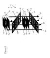
- FIG 1 is a cross-sectional view of an exemplary fuel cell stack 10 that includes a plurality of fuel cells 12.
- Figure 2 is an exploded view of a portion of fuel cell stack 10.
- Figure 3 is a schematic top plan view of fuel cell stack 10.
- Fuel cell stack 10 is known as a planar, interconnect-supported fuel cell stack, in which adjacent fuel cells 12 are separated by a plurality of interconnects 14, such that at least one interconnect 14 extends between each pair of adjacent fuel cells 12. More specifically, fuel cells 12 are coupled together in series such that fuel cell stack 10 includes a top stack plate 16, a bottom stack plate 18, and a plurality of interconnects 14 that are positioned between top stack plate 16 and bottom stack plate 18.
- each interconnect 14 is hollow and includes outer surface 22 and an internal chamber 24 therein.
- top stack plate 16, bottom stack plate 18, and interconnects 14, are each sized identically. In an alternative embodiment, at least one of top stack plate 16, bottom stack plate 18, and/or interconnect 14 is sized differently than the remaining fuel cell stack components.
- Stack plates 16 and 18 are fabricated from an electrically-conductive material. For example, stack plates 16 and 18 may be fabricated from conductive materials capable of operating at higher temperatures as described herein, such as, any material that is electrically conductive, or any material that if subject to oxidation, its oxide is conductive.
- Each interconnect 14 is also fabricated from an electrically conductive material, such as, but not limited to, conductive materials capable of operating at higher temperatures as described herein, such as, but not limited to, a stainless steel.
- a plurality of seal members 30 extend between adjacent interconnects 14. More specifically, adjacent fuel cells 12 are separated by a plurality of seal members 30, respectively, such that fuel cells 12 form a planar arrangement of solid oxide fuel cells. Seals 30 facilitate electrically isolating adjacent fuel cells 12 to prevent short-circuiting between cells 12.
- Each seal members 30 typically comprises a hollow electrical insulator (not shown) that may be fabricated from, but is not limited to, a ceramic material. In one embodiment, seal members 30 are fabricated from, but are not limited to being fabricated from, mica or a glass-mica composite material.
- a plurality of sealed passages 32 are defined. More specifically, in the exemplary embodiment, fuel cell reactants are supplied to, and channeled from, fuel cell stack 10 through sealed passages 32. More specifically, in the exemplary embodiment, fuel and air are both internally manifolded, and as such, passages 32 include a fuel inlet manifold 36, a fuel outlet manifold 38, an oxidant or air inlet manifold 40, and an oxidant or air outlet manifold 42. In an alternative embodiment, the oxidant or air is externally manifolded through fuel cell stack 10.
- Each interconnect chamber 24 extends from a first side 44 of interconnect 14 to a second side 48 of stack 10. More specifically, in the exemplary embodiment, chamber 24 has a substantially rectangular cross-sectional profile. In another embodiment, chamber 24 has a non-rectangular cross-sectional profile. In another embodiment, chamber 24 includes flow guides, baffles, and/or channeling features to facilitate distributing fuel and oxidant within interconnect 14.
- openings 60 extend at least partially through interconnect 14 and are in flow communication with interconnect chamber 24.
- openings 60 are arranged in a substantially colinear configuration, i.e., openings 60 are arranged in a linear sequence within a plurality of rows.
- each fuel cell 12 is formed from a plurality layers 70. More specifically, in the exemplary embodiment, fuel cell 12 includes an anode layer 72, an electrolyte layer 74, and a cathode layer 76 coupled together such that electrolyte layer 74 is sandwiched between layers 72 and 76, and such that a seal member 78 extends between each fuel cell 12 and each adjacent interconnect 14. Fuel cells 12 are coupled within fuel cell stack 10 to enable electricity to be conducted from one fuel cell anode layer 72 to a cathode layer 76 of an adjacent cell 12.
- electrolyte layer 74 is fabricated from a material such as, but is not limited to, yttrium-stabilized zirconia (YSZ), and cathode layer 76 ma include, but is not limited to, lanthanum strontium manganate (LSM).
- YSZ yttrium-stabilized zirconia
- LSM lanthanum strontium manganate
- Adjacent interconnects 14 are coupled together such that an oxidant flow area 80 is defined therebetween.
- Each oxidant flow area 80 is coupled in flow communication to air inlet manifold 40 and air outlet manifold 42.
- a fuel such as, but not limited to, a prereformed fuel, and/or a hydrocarbon which is reformed within fuel cell stack 10, is supplied to fuel cell stack 10 through fuel inlet manifold 36. After entering inlet manifold 36, fuel is routed through each interconnect chamber 24. Fuel flows over and reacts with each anode layer 72 prior to being discharged from fuel stack 10 through fuel outlet 38. Fuel and oxidant react in each fuel cell 12, which are connected in series within stack 10, to build voltage to useful levels. More specifically, the fuel reacts electrochemically with oxygen, supplied to stack 10 through air inlet manifold 40, to generate direct current (DC) electricity with water as the main product.
- DC direct current
- stack 10 is arranged such that the fuel cell reactants flow through stack 10 in opposite directions. In another embodiment, stack 10 is arranged such that the flow directions of the reactants flow through stack 10 are substantially parallel and in the same flow direction. Current is generated as the fuel and oxidant react, and a voltage potential is generated across stack 10.
- Figure 4 is a side view of fuel cell isolation assembly 100 that may be used with fuel cell stack 10.
- at least one fuel cell 102 has been determined, as described in more detail below, to have failed or have been damaged to a degree that may adversely affect stack performance.
- fuel cell isolation assembly 100 facilitates isolating the damaged fuel cell 102 from the remaining fuel cells 12 without ceasing operation of stack 10.
- Each fuel cell isolation assembly 100 includes a jumper 110 and an actuator 112 that is coupled to jumper 110 for controlling movement of jumper 110.
- Jumper 110 is fabricated from an electrically-conductive material and includes a radially outer surface 114 and an opposite radially inner surface 116 that extend longitudinally between an upper sidewall 118 and a lower sidewall 120.
- Jumper 110 is arcuately-shaped and extends arcuately between a first endwall (not shown) and a second endwall 122.
- each jumper 110 is substantially semi-circular.
- Each jumper 110 has a length L 1 that is longer than a distance D 1 measured between adjacent interconnects 14. More specifically, distance D 1 is measured between an upper surface 123 of a first interconnect 14, and a lower surface 124 of an adjacent second interconnect 14. As described in more detail below, jumper length L 1 enables each jumper 110 to electrically connect a pair of adjacent interconnects 14 together.
- a pair of jumpers 126 and 128 are coupled across respective opposite ends 130 and 132 of a pair of interconnects 14. More specifically, in the exemplary embodiment, jumper 126 is positioned within fuel inlet manifold 36 and jumper 128 is positioned within fuel exit manifold 40 to isolate fuel cell 102. In an alternative embodiment, only jumper 110 is used to isolate fuel cell 102. In another alternative embodiment, jumpers 110 are positioned within fuel inlet manifold 36, fuel outlet manifold 38 (shown in Figure 3), air inlet manifold 40, and air outlet manifold 42 (shown in Figure 3). Accordingly, each jumper 110 is contoured to substantially match the curved contour defined by an inner surface 138 of each respective sealed passage 32.
- each jumper 110 facilitates reducing the cross-sectional area of each jumper 110 within each passage 32 such that flow through passage 32 remains substantially unobstructed until each jumper 110 is positioned to isolate a failed fuel cell 102. Moreover, the curved contour, and the semi-circular shape of each jumper 110 enables a jumper 110 being positioned to isolate a newly-detected failed fuel cell 102 to be moved by actuator 112 through a respective passage 32 and past a jumper 110 already coupled to electrically isolate a failed fuel cell 110.
- actuator 112 is actuated by at least one of, but not limited to, a linear motor, a screw gear, or any other mechanical means suitable for selectively positioning jumper 110 as described herein. In another embodiment, actuator 112 is actuated by at least one of, but not limited to, pneumatic pressure, hydraulic pressure, electro-magnetic force, and electric power.
- each jumper 110 is rotatably coupled to an actuator 112 such that longitudinal movement, and rotational movement, of each jumper 110 with respect to fuel cell stack 10 is controlled by actuator 112. Accordingly, each jumper 110 is variably positionable within each respective sealed passage 32 such that any fuel cell 12 may be selectively isolated as described herein. More specifically, during normal operation of fuel cell stack 10, each jumper 110 remains coupled within a respective sealed passage 32 in a ready position 139, wherein jumpers 110 are not electrically coupled to any interconnects. Ready position 139 enables jumpers 110 to remain coupled within sealed passage 32 such that fluid flow through each respective sealed passage 32 into cells 12 remains substantially unobstructed until jumpers 110 are positioned to isolate a failed cell 102.
- fuel cell stack 10 includes a plurality of jumpers 110 that are not movable longitudinally through sealed passages 32, but rather jumpers 110 are integral to each cell 12 and are only moveable between ready position 139 and against interconnects 14, as described herein.
- jumpers 110 and/or interconnects 14 incorporate conducting and non-conducting surfaces such that jumpers 110 only short-circuit cells 12 when rotated from ready position 139 to isolate the failed cell 102.
- jumpers 110 When coupled in position, jumpers 110 electrically connect a pair of adjacent interconnects 14 together such that the pair of interconnects are "shortcircuited.” More specifically, each jumper 110 is positioned such that an outer surface 140 of jumper 110 is electrically coupled to each interconnect 14 that is adjacent the damaged fuel cell 102. Each jumper outer surface 140 includes features 142 that facilitates establishing an electrical connection between each jumper 110 and each interconnect. In addition, the combination of the contour of each jumper 110 and jumper external surface features 142 facilitates sealing contact between each jumper 110 and each interconnect 14. For example, in one embodiment, at least one of a wire mesh, a brush, and/or a metallic seal extends outwardly from jumper outer surface 140 to facilitate electrical contact and sealing between each jumper 110 and each respective interconnect 14.
- a jumper 110 is positioned to isolate cell 102 from the remaining fuel cells 12 such that fuel cell stack operation may continue without interruption. More specifically, after cell 102 is detected, in the exemplary embodiment, jumper 110 is moved longitudinally into ready position 139 through the use of actuator 112. Jumper 110 is then rotated such that jumper outer surface is electrically coupled between a pair of adjacent interconnects 14, and more specifically, such that fuel cell 102 is electrically isolated from the remaining fuel cells 12.
- jumper 110 when jumper 110 has electrically isolated fuel cell 102, the combination of the jumper contour and jumper external surface 140 facilitates sealing between jumper 110 and the pair of interconnects 14 to substantially prevent fuel flow and/or fuel and air flow (depending on which sealed passage jumper 110 is coupled with respect to stack 10) to fuel cell 102.
- fuel cell stack 10 may continue operation. Moreover, if multiple cells 102 have failed, additional jumpers 110 may be installed within the same fuel cell stack passage 32, as described herein.
- the performance of each individual cell is continuously monitored, and upon detection of a failed cell, a jumper is positioned to isolate that particular cell.
- the voltage and performance of individual cells are not monitored, but rather the overall performance of the fuel cell stack is monitored and held determinative of a failed fuel cell. More specifically, when the performance of the stack is reduced, the reduced performance is indicative of a failed fuel cell.
- a jumper is moved through the fuel inlet manifold and is coupled against each fuel cell while continuously monitoring the output performance of the fuel cell stack. When the performance monitoring indicates that the cell stack performance has increased, the jumper is then locked in position within the fuel inlet manifold. If additional jumpers are available within other manifolds, then those jumpers are also placed in position relative to the detected failed fuel cell.
- the fuel cell stack is coupled to a processor and a controller which enables the performance of the stack to be continuously monitored such that upon detection of a failed cell, a jumper is automatically positioned and coupled to the stack to effectively isolate the failed cell.
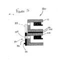
- FIG 5 is an enlarged schematic view of an alternative embodiment of fuel cell isolation assembly 180 that may be used with fuel cell stack 10.
- Fuel cell isolation assembly 180 is substantially similar to fuel cell isolation assembly 100 (shown in Figure 4) and components in fuel cell isolation assembly 180 that are identical to components of fuel cell isolation assembly 100 are identified in Figure 5 using the same reference numerals used in Figure 4. Accordingly, fuel cell isolation assembly 180 includes a jumper 182 that is controlled by actuator 112. Each jumper 182 includes a flow passageway 184 extending therethrough that in the exemplary embodiment, enables fuel flow to be supplied to each respective fuel cell 12. More specifically, fuel cell stack 10 includes a plurality of jumpers 182 that are each slidably coupled to a respective fuel cell 12 to selectively isolate that particular fuel cell 12 as described herein.
- each jumper 182 remains coupled within a respective sealed passage 32 in a ready position 190, wherein jumper passageway 184 is positioned to enable fuel flow to fuel cell 12, and such that fluid flow through each respective sealed passage 32 into every other cell 12 remains substantially unobstructed.
- jumper 182 is transitioned from ready position 190 into an isolation position 193 wherein that particular fuel cell 12 is isolated from the remaining fuel cells 12. More specifically, when transitioned into isolation position 193, passageway 184 is positioned against an insulating layer 194 extending between adjacent fuel cells 12 such that fuel flow to the failed cell 102 is prevented.
- FIG 6 is an enlarged schematic view of an alternative embodiment of fuel cell isolation assembly 200 that may be used with fuel cell stack 10.
- Fuel cell isolation assembly 200 is substantially similar to fuel cell isolation assembly 100 (shown in Figure 4) and components in fuel cell isolation assembly 200 that are identical to components of fuel cell isolation assembly 100 are identified in Figure 6 using the same reference numerals used in Figure 4. Accordingly, fuel cell isolation assembly 200 includes jumper 110 and actuator 112.
- Fuel cell assembly 200 also includes a jumper reloader system 202 that enables, as described in more detail below, additional jumpers 110 to be inserted within fuel cell stack 10 during operation of fuel cell stack 10.
- Jumper reloader system 202 includes an insertion housing 204 that is coupled in flow communication to fuel inlet manifold 36.
- additional jumper reloader systems are coupled to other sealed passages 32.
- a valve 206 such as a globe valve, is coupled between fuel inlet manifold 36 and insertion housing 204 to selectively control flow communication between manifold 36 and insertion housing 204. When valve 206 is in a closed position, insertion housing 204 is substantially isolated from fuel inlet manifold 36.
- valve 206 When valve 206 is rotated to an open position, fuel inlet manifold 36 and insertion housing 204 are coupled in flow communication, such that a jumper 110 may be inserted through valve 206 and into position, as described above in more detail, relative to a failed fuel cell 102 (shown in Figure 4.
- Housing 204 includes an actuator opening 210 and an access opening 212.
- Actuator opening 210 enables actuator 112 to be coupled to jumper 110 through housing 204 for controlling positioning of jumper 110.
- Access opening 212 is sized to receive jumpers 110 therethrough and includes a variably positioned door 214. When closed, door 214 substantially seals opening 210. When opened, door 214 enables additional jumpers 100 to be coupled to actuator 112 while fuel cell stack 10 remains in operation.
- valve 206 When a damaged or failed fuel cell 102 is detected, valve 206 is rotated to an open position, and a jumper 110 is positioned to isolate cell 102 from the remaining fuel cells 12, as described in more detail above.
- jumper reloader system 202 When an additional fuel cell 12 is determined to have failed, jumper reloader system 202 enables additional jumpers 110 to be installed while fuel cell stack 10 remains in operation.
- valve 206 is rotated closed to effectively isolate housing 204 from fuel inlet manifold 36.
- An additional jumper 110 is then coupled to actuator 112 through access door 214, and door 214 is then rotated closed to effectively seal access opening 212.
- Valve 206 is then opened and the additional jumper 110 is then moved into position relative to fuel cell stack 10.
- the curved contour, and the semi-circular shape of each jumper 110 enables the additional jumper 110 to be moved through manifold 36 and past a jumper 110 already coupled in position relative to fuel cell stack 10, while fuel cell stack 10 remains in operation.
- FIG 7 is a side view of another alternative embodiment of a fuel cell isolation device 250 that may be used with fuel cell stack 10.
- Fuel cell isolation assembly 250 is substantially similar to fuel cell isolation assembly 100 (shown in Figure 4) and fuel cell isolation assembly 200 (shown in Figure 6), and components in fuel cell isolation assembly 250 that are identical to components of fuel cell isolation assemblies 100 and/or 250 are identified in Figure 7 using the same reference numerals used in Figures 4 and 6. Accordingly, fuel cell isolation assembly 250 includes jumper 110 and actuator 112.
- Fuel cell assembly 250 also includes a jumper positioning system 252 that facilitates, as described in more detail below, positioning each jumper 110 in position relative to each fuel cell 12 coupled within stack 10.
- Jumper positioning system 252 includes a plurality of keyway assemblies 260 and at least one key 262.
- each keyway assembly 260 includes a support wall 264 that extends between adjacent interconnects 14 adjacent interconnect first end 44.
- keyway assemblies 260 are included in other sealed passages 32.
- Each support wall 264 includes a keyway 266 and a flow access opening 268 that, in the exemplary embodiment, enables fuel to flow from inlet manifold 36 between adjacent interconnects 14 and towards each fuel cell 12, as described in more detail above.
- Keyway 266 is defined within each support wall 264 and is sized to receive key 262 therein.
- keyway 266 is substantially dovetail-shaped. In alternative embodiments, keyway 266 is non-dovetailed shaped.
- Each key 266 extends radially outward from jumper outer surface 140 and is sized to be received within keyway 266 when jumper 110 is rotated into position relative to a failed fuel cell 102. Accordingly, when jumper 110 is rotated into position, and key 266 is received within keyway 266, jumper 110 is positioned relative to fuel cell 102 such that adjacent interconnects 14 are electrically coupled together as described in more detail above.
- the above-described fuel cell isolation assemblies enable a failed fuel cell to be electrically isolated without interrupting operation of the fuel cell stack.
- the isolation assemblies each include a jumper coupled to an actuator that controls movement of the isolation assemblies.
- the jumper is fabricated from an electrically conductive material and is sized to extend between adjacent interconnects such that the jumper may electrically connects a pair of adjacent interconnects. Accordingly, as a result, failed fuel cells may be isolated from the remaining fuel cells while the fuel cell stack remains operational and in a cost-effective and reliable manner.
- each fuel cell stack component can also be used in combination with other fuel cell stack components.
- the relative positions of the anode and the cathode within the stack may be exchanged, and similarly passages defined for fuel flow and oxidant may also be exchanged.
- each fuel cell isolation assembly can also be used in combination with other fuel cell isolation assemblies and with other fuel cell stack components.
Abstract
Description
- This invention relates generally to power generation, and more specifically, to methods and apparatus for assembling solid oxide fuel cells.
- At least some known power generation systems use fuel cells to produce power. A fuel cell is an electrochemical device that converts chemical energy produced by a reaction directly into electrical energy. Known fuel cells typically include an anode, also known as a fuel electrode, a cathode, also known as an oxidant electrode, and an electrolyte. Such fuel cells are electrochemical devices, similar to batteries, which react fuel and oxidant to produce electricity. However, unlike batteries, fuel such as hydrogen and oxidant such as air are supplied continuously to the fuel cell such that it continues to produce power so long as such reactants are provided.
- A fuel cell produces electricity by catalyzing fuel and oxidant into ionized atomic hydrogen and oxygen at, respectively, the anode and cathode. The electrons removed from hydrogen in the ionization process at the anode are conducted to the cathode where they ionize the oxygen. In the case of a solid oxide fuel cell, the oxygen ions are conducted through the electrolyte where they combine with ionized hydrogen to form water as a waste product and complete the process. The electrolyte is otherwise impermeable to both fuel and oxidant and merely conducts oxygen ions. This series of electrochemical reactions is the sole means of generating electric power within the fuel cell. It is therefore desirable to reduce or eliminate any mixing of the reactants, as such mixing would result in a different combination such as combustion which produces no electric power and therefore reduces the efficiency of the fuel cell.
- Individual fuel cells produce power at low voltage, typically less than about 1 Volt per cell. The cells are therefore typically assembled in electrical series in a fuel cell stack to produce power at useful voltages. To create a fuel stack, an interconnecting member is used to connect the adjacent fuel cells together in electrical series. In such an arrangement, fuel flows at a substantially equal flow rate to each of the fuel cells. As a result, the failure of a single fuel cell may cause the failure of the entire fuel stack.
- To enable fuel stacks to continue to operate after a fuel cell fails, at least some known fuel stacks include a plurality of valves which are magnetically actuated from external to the cell to restrict fuel flow to the failed cell. However, actuating such valves will limit fuel flow to affected cells without isolating them electrically from the other cells, and as such, may severely limit the continued operation of the fuel cell stack. In at least some other known fuel cell stacks, a conductor is inserted within the failed fuel cell to short-circuit the cell such that the fuel cell stack may be operable with the remaining fuel cells. However, because at least a portion of the stack must be disassembled to insert the conductor, the fuel cell stack can not be operated during the insertion of the conductor. Furthermore, returning the stack to a safe working and operating temperature may shorten the useful life of the stack due to thermal cycling damage.
- In one aspect of the present invention, a fuel cell stack assembly is provided. The fuel cell stack assembly includes at least a first fuel cell and a second fuel cell electrically coupled together such that at least one sealed passage extends between the first and second fuel cells. Each of the fuel cells includes at least one hollow manifold that includes a wall extending between a first end and a second end. Each wall defines a chamber therein, and includes at least one opening extending therethrough in flow communication with the chamber. The fuel cell stack assembly also includes at least one fuel cell isolation device coupled in flow communication with each fuel cell hollow manifold. The at least one fuel cell isolation device is variably positionable during fuel cell stack assembly operation for selectively stopping fluid flow through at least one of the fuel cells.
- In another aspect of the invention, a fuel cell stack coupled in flow communication to an air source and a fuel source is provided. The fuel cell stack includes at least three fuel cells coupled together in flow communication such that at least one sealed passage extends between the at least three fuel cells, and a plurality of interconnects that electrically couple the at least three fuel cells together such that at least one interconnect extends between each adjacent pair of fuel cells. The fuel cell stack also includes at least one fuel cell isolation device coupled in flow communication with each of the at least three fuel cells. The at least one fuel cell isolation device is selectively positionable during fuel cell stack operation to electrically isolate at least one of the fuel cells from the remaining fuel cells.
- In yet another aspect, a method for assembling a fuel cell stack is provided. The method includes electrically coupling a first fuel cell to a second fuel cell such that at least one seal passage extends between the first and second fuel cells, and coupling at least one fuel cell isolation device within the at least one seal passage such that the at least one fuel cell isolation device is variably positionable to electrically isolate at least one of the first and second fuel cells during operation of the fuel cell stack.
- In a further aspect, a method for operating a fuel cell stack assembly including at least two fuel cells that are electrically coupled in series together is provided. The method includes determining a fault exists within an operating fuel cell stack assembly, electrically isolating and stopping reactant flow to at least one of the fuel cells during operation of the fuel cell stack assembly, and continuing operation of the fuel cell stack assembly with at least one fuel cell electrically isolated from the remaining fuel cells within the fuel cell stack assembly.
- Embodiments of the invention will now be described, by way of example, with reference to the accompanying drawings, in which:
- Figure 1 is a cross-sectional view of an exemplary fuel cell stack;
- Figure 2 is an exploded view of a portion of the fuel cell stack shown in Figure 1;
- Figure 3 is a schematic top plan view of the fuel cell stack shown in Figure 1;
- Figure 4 is a cross-sectional view of a fuel cell isolation assembly that may be used with the fuel cell stack shown in Figure 1;
- Figure 5 is an enlarged partial cross-sectional view of an alternative embodiment of a fuel cell isolation assembly that may be used with the fuel cell stack shown in Figure 1;
- Figure 6 is an enlarged schematic view of a further alternative embodiment of a fuel cell isolation assembly that may be used with the fuel cell stack shown in Figure 1; and
- Figure 7 is a cross-sectional view of another alternative embodiment of a fuel cell isolation device that may be used with the fuel cell stack shown in Figure 1.
-
- Figure 1 is a cross-sectional view of an exemplary
fuel cell stack 10 that includes a plurality offuel cells 12. Figure 2 is an exploded view of a portion offuel cell stack 10. Figure 3 is a schematic top plan view offuel cell stack 10.Fuel cell stack 10 is known as a planar, interconnect-supported fuel cell stack, in whichadjacent fuel cells 12 are separated by a plurality ofinterconnects 14, such that at least oneinterconnect 14 extends between each pair ofadjacent fuel cells 12. More specifically,fuel cells 12 are coupled together in series such thatfuel cell stack 10 includes atop stack plate 16, abottom stack plate 18, and a plurality ofinterconnects 14 that are positioned betweentop stack plate 16 andbottom stack plate 18. In the exemplary embodiment, eachinterconnect 14 is hollow and includesouter surface 22 and aninternal chamber 24 therein. - In the exemplary embodiment,
top stack plate 16,bottom stack plate 18, andinterconnects 14, are each sized identically. In an alternative embodiment, at least one oftop stack plate 16,bottom stack plate 18, and/orinterconnect 14 is sized differently than the remaining fuel cell stack components.Stack plates stack plates interconnect 14 is also fabricated from an electrically conductive material, such as, but not limited to, conductive materials capable of operating at higher temperatures as described herein, such as, but not limited to, a stainless steel. - A plurality of
seal members 30 extend betweenadjacent interconnects 14. More specifically,adjacent fuel cells 12 are separated by a plurality ofseal members 30, respectively, such thatfuel cells 12 form a planar arrangement of solid oxide fuel cells.Seals 30 facilitate electrically isolatingadjacent fuel cells 12 to prevent short-circuiting betweencells 12. Eachseal members 30 typically comprises a hollow electrical insulator (not shown) that may be fabricated from, but is not limited to, a ceramic material. In one embodiment,seal members 30 are fabricated from, but are not limited to being fabricated from, mica or a glass-mica composite material. - When
seal members 30 are coupled betweenadjacent interconnects 14, a plurality of sealedpassages 32 are defined. More specifically, in the exemplary embodiment, fuel cell reactants are supplied to, and channeled from,fuel cell stack 10 through sealedpassages 32. More specifically, in the exemplary embodiment, fuel and air are both internally manifolded, and as such,passages 32 include afuel inlet manifold 36, afuel outlet manifold 38, an oxidant orair inlet manifold 40, and an oxidant orair outlet manifold 42. In an alternative embodiment, the oxidant or air is externally manifolded throughfuel cell stack 10. - Each
interconnect chamber 24 extends from afirst side 44 ofinterconnect 14 to asecond side 48 ofstack 10. More specifically, in the exemplary embodiment,chamber 24 has a substantially rectangular cross-sectional profile. In another embodiment,chamber 24 has a non-rectangular cross-sectional profile. In another embodiment,chamber 24 includes flow guides, baffles, and/or channeling features to facilitate distributing fuel and oxidant withininterconnect 14. - A plurality of openings 60 extend at least partially through
interconnect 14 and are in flow communication withinterconnect chamber 24. In the exemplary embodiment, openings 60 are arranged in a substantially colinear configuration, i.e., openings 60 are arranged in a linear sequence within a plurality of rows. - In the exemplary embodiment, each
fuel cell 12 is formed from a plurality layers 70. More specifically, in the exemplary embodiment,fuel cell 12 includes ananode layer 72, anelectrolyte layer 74, and a cathode layer 76 coupled together such thatelectrolyte layer 74 is sandwiched betweenlayers 72 and 76, and such that aseal member 78 extends between eachfuel cell 12 and eachadjacent interconnect 14.Fuel cells 12 are coupled withinfuel cell stack 10 to enable electricity to be conducted from one fuelcell anode layer 72 to a cathode layer 76 of anadjacent cell 12. In one embodiment,electrolyte layer 74 is fabricated from a material such as, but is not limited to, yttrium-stabilized zirconia (YSZ), and cathode layer 76 ma include, but is not limited to, lanthanum strontium manganate (LSM). -
Adjacent interconnects 14 are coupled together such that an oxidant flow area 80 is defined therebetween. Each oxidant flow area 80 is coupled in flow communication toair inlet manifold 40 andair outlet manifold 42. - During operation, a fuel, such as, but not limited to, a prereformed fuel, and/or a hydrocarbon which is reformed within
fuel cell stack 10, is supplied tofuel cell stack 10 throughfuel inlet manifold 36. After enteringinlet manifold 36, fuel is routed through eachinterconnect chamber 24. Fuel flows over and reacts with eachanode layer 72 prior to being discharged fromfuel stack 10 throughfuel outlet 38. Fuel and oxidant react in eachfuel cell 12, which are connected in series withinstack 10, to build voltage to useful levels. More specifically, the fuel reacts electrochemically with oxygen, supplied to stack 10 throughair inlet manifold 40, to generate direct current (DC) electricity with water as the main product. In the exemplary embodiment, stack 10 is arranged such that the fuel cell reactants flow throughstack 10 in opposite directions. In another embodiment, stack 10 is arranged such that the flow directions of the reactants flow throughstack 10 are substantially parallel and in the same flow direction. Current is generated as the fuel and oxidant react, and a voltage potential is generated acrossstack 10. - Figure 4 is a side view of fuel
cell isolation assembly 100 that may be used withfuel cell stack 10. In the exemplary embodiment, at least onefuel cell 102 has been determined, as described in more detail below, to have failed or have been damaged to a degree that may adversely affect stack performance. During stack operation, fuelcell isolation assembly 100, as described in more detail below, facilitates isolating the damagedfuel cell 102 from the remainingfuel cells 12 without ceasing operation ofstack 10. - Each fuel
cell isolation assembly 100 includes ajumper 110 and anactuator 112 that is coupled tojumper 110 for controlling movement ofjumper 110.Jumper 110 is fabricated from an electrically-conductive material and includes a radiallyouter surface 114 and an opposite radiallyinner surface 116 that extend longitudinally between anupper sidewall 118 and alower sidewall 120.Jumper 110 is arcuately-shaped and extends arcuately between a first endwall (not shown) and asecond endwall 122. In the exemplary embodiment, eachjumper 110 is substantially semi-circular. - Each
jumper 110 has a length L1 that is longer than a distance D1 measured betweenadjacent interconnects 14. More specifically, distance D1 is measured between anupper surface 123 of afirst interconnect 14, and alower surface 124 of an adjacentsecond interconnect 14. As described in more detail below, jumper length L1 enables eachjumper 110 to electrically connect a pair ofadjacent interconnects 14 together. - In the exemplary embodiment, a pair of
jumpers interconnects 14. More specifically, in the exemplary embodiment,jumper 126 is positioned withinfuel inlet manifold 36 andjumper 128 is positioned withinfuel exit manifold 40 to isolatefuel cell 102. In an alternative embodiment,only jumper 110 is used to isolatefuel cell 102. In another alternative embodiment,jumpers 110 are positioned withinfuel inlet manifold 36, fuel outlet manifold 38 (shown in Figure 3),air inlet manifold 40, and air outlet manifold 42 (shown in Figure 3). Accordingly, eachjumper 110 is contoured to substantially match the curved contour defined by aninner surface 138 of each respective sealedpassage 32. The curved contour of eachjumper 110 facilitates reducing the cross-sectional area of eachjumper 110 within eachpassage 32 such that flow throughpassage 32 remains substantially unobstructed until eachjumper 110 is positioned to isolate a failedfuel cell 102. Moreover, the curved contour, and the semi-circular shape of eachjumper 110 enables ajumper 110 being positioned to isolate a newly-detected failedfuel cell 102 to be moved byactuator 112 through arespective passage 32 and past ajumper 110 already coupled to electrically isolate a failedfuel cell 110. In one embodiment,actuator 112 is actuated by at least one of, but not limited to, a linear motor, a screw gear, or any other mechanical means suitable for selectively positioningjumper 110 as described herein. In another embodiment,actuator 112 is actuated by at least one of, but not limited to, pneumatic pressure, hydraulic pressure, electro-magnetic force, and electric power. - In the exemplary embodiment, each
jumper 110 is rotatably coupled to anactuator 112 such that longitudinal movement, and rotational movement, of eachjumper 110 with respect tofuel cell stack 10 is controlled byactuator 112. Accordingly, eachjumper 110 is variably positionable within each respective sealedpassage 32 such that anyfuel cell 12 may be selectively isolated as described herein. More specifically, during normal operation offuel cell stack 10, eachjumper 110 remains coupled within a respective sealedpassage 32 in aready position 139, whereinjumpers 110 are not electrically coupled to any interconnects.Ready position 139 enablesjumpers 110 to remain coupled within sealedpassage 32 such that fluid flow through each respective sealedpassage 32 intocells 12 remains substantially unobstructed untiljumpers 110 are positioned to isolate a failedcell 102. In an alternative embodiment,fuel cell stack 10 includes a plurality ofjumpers 110 that are not movable longitudinally through sealedpassages 32, but ratherjumpers 110 are integral to eachcell 12 and are only moveable betweenready position 139 and againstinterconnects 14, as described herein. In such an embodiment, eitherjumpers 110 and/or interconnects 14 incorporate conducting and non-conducting surfaces such thatjumpers 110 only short-circuit cells 12 when rotated fromready position 139 to isolate the failedcell 102. - When coupled in position,
jumpers 110 electrically connect a pair ofadjacent interconnects 14 together such that the pair of interconnects are "shortcircuited." More specifically, eachjumper 110 is positioned such that an outer surface 140 ofjumper 110 is electrically coupled to eachinterconnect 14 that is adjacent the damagedfuel cell 102. Each jumper outer surface 140 includesfeatures 142 that facilitates establishing an electrical connection between eachjumper 110 and each interconnect. In addition, the combination of the contour of eachjumper 110 and jumper external surface features 142 facilitates sealing contact between eachjumper 110 and eachinterconnect 14. For example, in one embodiment, at least one of a wire mesh, a brush, and/or a metallic seal extends outwardly from jumper outer surface 140 to facilitate electrical contact and sealing between eachjumper 110 and eachrespective interconnect 14. - During fuel cell stack operation, when a damaged or failed
fuel cell 102 is detected, as described in more detail below, ajumper 110 is positioned to isolatecell 102 from the remainingfuel cells 12 such that fuel cell stack operation may continue without interruption. More specifically, aftercell 102 is detected, in the exemplary embodiment,jumper 110 is moved longitudinally intoready position 139 through the use ofactuator 112.Jumper 110 is then rotated such that jumper outer surface is electrically coupled between a pair ofadjacent interconnects 14, and more specifically, such thatfuel cell 102 is electrically isolated from the remainingfuel cells 12. Moreover, whenjumper 110 has electrically isolatedfuel cell 102, the combination of the jumper contour and jumper external surface 140 facilitates sealing betweenjumper 110 and the pair ofinterconnects 14 to substantially prevent fuel flow and/or fuel and air flow (depending on which sealedpassage jumper 110 is coupled with respect to stack 10) tofuel cell 102. - Accordingly, because
cell 102 is electrically isolated, and because fuel flow and/or fuel and air flow tocell 102 is substantially prevented,fuel cell stack 10 may continue operation. Moreover, ifmultiple cells 102 have failed,additional jumpers 110 may be installed within the same fuelcell stack passage 32, as described herein. - In the exemplary embodiment, the performance of each individual cell is continuously monitored, and upon detection of a failed cell, a jumper is positioned to isolate that particular cell. In an alternative embodiment, the voltage and performance of individual cells are not monitored, but rather the overall performance of the fuel cell stack is monitored and held determinative of a failed fuel cell. More specifically, when the performance of the stack is reduced, the reduced performance is indicative of a failed fuel cell. After detecting a reduction in stack performance, a jumper is moved through the fuel inlet manifold and is coupled against each fuel cell while continuously monitoring the output performance of the fuel cell stack. When the performance monitoring indicates that the cell stack performance has increased, the jumper is then locked in position within the fuel inlet manifold. If additional jumpers are available within other manifolds, then those jumpers are also placed in position relative to the detected failed fuel cell.
- In another embodiment, the fuel cell stack is coupled to a processor and a controller which enables the performance of the stack to be continuously monitored such that upon detection of a failed cell, a jumper is automatically positioned and coupled to the stack to effectively isolate the failed cell.
- Figure 5 is an enlarged schematic view of an alternative embodiment of fuel
cell isolation assembly 180 that may be used withfuel cell stack 10. Fuelcell isolation assembly 180 is substantially similar to fuel cell isolation assembly 100 (shown in Figure 4) and components in fuelcell isolation assembly 180 that are identical to components of fuelcell isolation assembly 100 are identified in Figure 5 using the same reference numerals used in Figure 4. Accordingly, fuelcell isolation assembly 180 includes ajumper 182 that is controlled byactuator 112. Eachjumper 182 includes aflow passageway 184 extending therethrough that in the exemplary embodiment, enables fuel flow to be supplied to eachrespective fuel cell 12. More specifically,fuel cell stack 10 includes a plurality ofjumpers 182 that are each slidably coupled to arespective fuel cell 12 to selectively isolate thatparticular fuel cell 12 as described herein. More specifically, during normal operation offuel cell stack 10, eachjumper 182 remains coupled within a respective sealedpassage 32 in aready position 190, whereinjumper passageway 184 is positioned to enable fuel flow tofuel cell 12, and such that fluid flow through each respective sealedpassage 32 into everyother cell 12 remains substantially unobstructed. - When a failed
fuel cell 102 requires isolation,jumper 182 is transitioned fromready position 190 into anisolation position 193 wherein thatparticular fuel cell 12 is isolated from the remainingfuel cells 12. More specifically, when transitioned intoisolation position 193,passageway 184 is positioned against an insulatinglayer 194 extending betweenadjacent fuel cells 12 such that fuel flow to the failedcell 102 is prevented. - Figure 6 is an enlarged schematic view of an alternative embodiment of fuel
cell isolation assembly 200 that may be used withfuel cell stack 10. Fuelcell isolation assembly 200 is substantially similar to fuel cell isolation assembly 100 (shown in Figure 4) and components in fuelcell isolation assembly 200 that are identical to components of fuelcell isolation assembly 100 are identified in Figure 6 using the same reference numerals used in Figure 4. Accordingly, fuelcell isolation assembly 200 includesjumper 110 andactuator 112.Fuel cell assembly 200 also includes a jumper reloader system 202 that enables, as described in more detail below,additional jumpers 110 to be inserted withinfuel cell stack 10 during operation offuel cell stack 10. - Jumper reloader system 202 includes an
insertion housing 204 that is coupled in flow communication to fuelinlet manifold 36. In alternative embodiments, additional jumper reloader systems are coupled to other sealedpassages 32. More specifically, avalve 206, such as a globe valve, is coupled betweenfuel inlet manifold 36 andinsertion housing 204 to selectively control flow communication betweenmanifold 36 andinsertion housing 204. Whenvalve 206 is in a closed position,insertion housing 204 is substantially isolated fromfuel inlet manifold 36. Whenvalve 206 is rotated to an open position,fuel inlet manifold 36 andinsertion housing 204 are coupled in flow communication, such that ajumper 110 may be inserted throughvalve 206 and into position, as described above in more detail, relative to a failed fuel cell 102 (shown in Figure 4. -
Housing 204 includes anactuator opening 210 and anaccess opening 212.Actuator opening 210 enablesactuator 112 to be coupled tojumper 110 throughhousing 204 for controlling positioning ofjumper 110.Access opening 212 is sized to receivejumpers 110 therethrough and includes a variably positioneddoor 214. When closed,door 214 substantially sealsopening 210. When opened,door 214 enablesadditional jumpers 100 to be coupled toactuator 112 whilefuel cell stack 10 remains in operation. - During fuel cell stack operation, when a damaged or failed
fuel cell 102 is detected,valve 206 is rotated to an open position, and ajumper 110 is positioned to isolatecell 102 from the remainingfuel cells 12, as described in more detail above. When anadditional fuel cell 12 is determined to have failed, jumper reloader system 202 enablesadditional jumpers 110 to be installed whilefuel cell stack 10 remains in operation. - More specifically, when an additional jumper is to be installed, initially
valve 206 is rotated closed to effectively isolatehousing 204 fromfuel inlet manifold 36. Anadditional jumper 110 is then coupled toactuator 112 throughaccess door 214, anddoor 214 is then rotated closed to effectively sealaccess opening 212.Valve 206 is then opened and theadditional jumper 110 is then moved into position relative tofuel cell stack 10. The curved contour, and the semi-circular shape of eachjumper 110 enables theadditional jumper 110 to be moved throughmanifold 36 and past ajumper 110 already coupled in position relative tofuel cell stack 10, whilefuel cell stack 10 remains in operation. - Figure 7 is a side view of another alternative embodiment of a fuel
cell isolation device 250 that may be used withfuel cell stack 10. Fuelcell isolation assembly 250 is substantially similar to fuel cell isolation assembly 100 (shown in Figure 4) and fuel cell isolation assembly 200 (shown in Figure 6), and components in fuelcell isolation assembly 250 that are identical to components of fuelcell isolation assemblies 100 and/or 250 are identified in Figure 7 using the same reference numerals used in Figures 4 and 6. Accordingly, fuelcell isolation assembly 250 includesjumper 110 andactuator 112.Fuel cell assembly 250 also includes ajumper positioning system 252 that facilitates, as described in more detail below, positioning eachjumper 110 in position relative to eachfuel cell 12 coupled withinstack 10. -
Jumper positioning system 252 includes a plurality ofkeyway assemblies 260 and at least onekey 262. Specifically, eachkeyway assembly 260 includes asupport wall 264 that extends betweenadjacent interconnects 14 adjacent interconnectfirst end 44. In an alternative embodiment,keyway assemblies 260 are included in other sealedpassages 32. Eachsupport wall 264 includes akeyway 266 and a flow access opening 268 that, in the exemplary embodiment, enables fuel to flow frominlet manifold 36 betweenadjacent interconnects 14 and towards eachfuel cell 12, as described in more detail above.Keyway 266 is defined within eachsupport wall 264 and is sized to receive key 262 therein. In the exemplary embodiment,keyway 266 is substantially dovetail-shaped. In alternative embodiments,keyway 266 is non-dovetailed shaped. - Each key 266 extends radially outward from jumper outer surface 140 and is sized to be received within
keyway 266 whenjumper 110 is rotated into position relative to a failedfuel cell 102. Accordingly, whenjumper 110 is rotated into position, and key 266 is received withinkeyway 266,jumper 110 is positioned relative tofuel cell 102 such thatadjacent interconnects 14 are electrically coupled together as described in more detail above. - The above-described fuel cell isolation assemblies enable a failed fuel cell to be electrically isolated without interrupting operation of the fuel cell stack. The isolation assemblies each include a jumper coupled to an actuator that controls movement of the isolation assemblies. The jumper is fabricated from an electrically conductive material and is sized to extend between adjacent interconnects such that the jumper may electrically connects a pair of adjacent interconnects. Accordingly, as a result, failed fuel cells may be isolated from the remaining fuel cells while the fuel cell stack remains operational and in a cost-effective and reliable manner.
- Exemplary embodiments of fuel cell stacks and fuel cell isolation assemblies are described above in detail. Neither the fuel cell stacks nor the fuel cell isolation assemblies are limited to the specific embodiments described herein, but rather, components of each stack or assembly may be utilized independently and separately from other components described herein. Each fuel cell stack component can also be used in combination with other fuel cell stack components. For example, in certain embodiments, the relative positions of the anode and the cathode within the stack may be exchanged, and similarly passages defined for fuel flow and oxidant may also be exchanged. Moreover, each fuel cell isolation assembly can also be used in combination with other fuel cell isolation assemblies and with other fuel cell stack components.
Claims (10)
- A fuel cell stack assembly (10) comprising:at least a first fuel cell (12) and a second fuel cell (102) electrically coupled together such that at least one sealed passage (32) extends between said first and second fuel cells, each said fuel cell comprising at least one hollow manifold (40) comprising a wall extending between a first end and a second end, each said wall defining a chamber (24) therein, said wall comprising at least one opening (60) extending therethrough in flow communication with said chamber; andat least one fuel cell isolation device (100) coupled in flow communication with each said fuel cell hollow manifold, said at least one fuel cell isolation device variably positionable during fuel cell stack assembly operation for selectively stopping fluid flow through at least one of said fuel cells.
- A fuel cell stack assembly (10) in accordance with Claim 1 wherein at least a portion of said at least one sealed passage (32) has a substantially circular cross-sectional profile, said at least one fuel cell isolation device (100) has a substantially semi-circular cross-sectional profile.
- A fuel cell stack assembly (10) in accordance with Claim 1 further comprising a fuel inlet (36) configured to channel fuel to said first (12) and second (102) fuel cells, and a fuel outlet (38) configured to channel fuel from said first and second fuel cells, said at least one fuel cell isolation device positioned within at least one of said fuel inlet and said fuel outlet.
- A fuel cell stack assembly (10) in accordance with Claim 1 wherein adjacent fuel cells (12) are separated by a distance (D1), said at least one fuel cell isolation device (100) has a length (L1) that is longer than said fuel cell separation distance.
- A fuel cell stack assembly (10) in accordance with Claim 1 wherein at least one interconnect (14) extends between adjacent fuel cells (12), said at least one fuel cell isolation device (100) is configured to electrically couple a pair of adjacent interconnects together.
- A fuel cell stack assembly (10) in accordance with Claim 1 wherein said at least one fuel cell isolation device (100) comprises an external surface (114), at least one of a wire mesh (142), a metallic seal, and a brush extends outwardly from said external surface.
- A fuel cell stack assembly (10) in accordance with Claim 1 wherein said at least one fuel cell isolation device (100) is coupled to at least one actuator (112) for controlling movement of said at least one fuel cell isolation device.
- A fuel cell stack assembly (10) in accordance with Claim 1 wherein each said fuel cell (12) further comprises at least one keyway (266) positioned adjacent at least one of said manifold first end and said manifold second end, said keyway facilitates positioning said at least one fuel cell isolation device (100).
- A fuel cell stack assembly (10) in accordance with Claim 1 wherein each said fuel cell (12) further comprises at least one pre-positioned fuel cell isolation device (100) that is movable by an actuator (112).
- A fuel cell stack assembly (10) in accordance with Claim 1 further comprising further comprising a fuel inlet (36), a fuel outlet (38), and at least one valve (200), said fuel inlet for channeling fuel to said first and second fuel cells (12, 102), said fuel outlet for channeling fuel from said first and second fuel cells, said valve for selectively cell isolation device within the at least one seal passage further comprises coupling the at least one fuel cell isolation device within the at least one seal passage to enable at least one of air flow and fuel flow to be selectively stopped to at least one of the first and second fuel cells during operation of the fuel cell stack.
Applications Claiming Priority (2)
| Application Number | Priority Date | Filing Date | Title |
|---|---|---|---|
| US665942 | 1991-03-06 | ||
| US10/665,942 US7358005B2 (en) | 2003-09-18 | 2003-09-18 | Methods and apparatus for isolating solid oxide fuel cells |
Publications (2)
| Publication Number | Publication Date |
|---|---|
| EP1517393A2 true EP1517393A2 (en) | 2005-03-23 |
| EP1517393A3 EP1517393A3 (en) | 2008-07-02 |
Family
ID=34194772
Family Applications (1)
| Application Number | Title | Priority Date | Filing Date |
|---|---|---|---|
| EP04255641A Withdrawn EP1517393A3 (en) | 2003-09-18 | 2004-09-16 | Methods and apparatus for assembling solid oxide fuel cells |
Country Status (4)
| Country | Link |
|---|---|
| US (1) | US7358005B2 (en) |
| EP (1) | EP1517393A3 (en) |
| JP (1) | JP2005100987A (en) |
| CN (1) | CN1599115A (en) |
Cited By (3)
| Publication number | Priority date | Publication date | Assignee | Title |
|---|---|---|---|---|
| WO2010005415A1 (en) * | 2008-07-09 | 2010-01-14 | Utc Power Corporation | Fuel cell stack conditioned to operate safely with failed cells |
| EP2898560A4 (en) * | 2012-09-21 | 2016-05-18 | Bloom Energy Corp | Systems and methods for bypassing fuel cells |
| DE102017211610A1 (en) | 2017-07-07 | 2019-01-10 | Audi Ag | Enable a fuel cell |
Families Citing this family (14)
| Publication number | Priority date | Publication date | Assignee | Title |
|---|---|---|---|---|
| US20060246331A1 (en) * | 2005-04-29 | 2006-11-02 | Steinbroner Matthew P | Partitioned fuel cell stacks and fuel cell systems including the same |
| US7927752B2 (en) * | 2007-03-09 | 2011-04-19 | GM Global Technology Operations LLC | Individual cell shorting during startup and shutdown using an integrated switch |
| JP5160811B2 (en) * | 2007-05-16 | 2013-03-13 | 日本電信電話株式会社 | Solid oxide fuel cell stack |
| TWI416791B (en) * | 2007-07-04 | 2013-11-21 | Wistron Corp | A coupling structure of fuel cells is disclosed |
| US20100216053A1 (en) * | 2007-07-09 | 2010-08-26 | Atomic Energy Council - Institute Of Nuclear Energy Research | Stack flow path of planar solid oxide fuel cell |
| JP5213014B2 (en) * | 2007-08-02 | 2013-06-19 | 行政院原子能委員会核能研究所 | Planar solid oxide fuel cell |
| US8268504B2 (en) * | 2008-12-22 | 2012-09-18 | General Electric Company | Thermomechanical sealing of interconnect manifolds in fuel cell stacks |
| US8602996B2 (en) | 2010-06-01 | 2013-12-10 | Cardiac Pacemakers, Inc. | Integrating device-based sensors and bedside biomarker assays to detect worsening heart failure |
| KR101180157B1 (en) | 2010-12-28 | 2012-09-05 | 주식회사 포스코 | Apparatus for treating of poor unit cell of solid oxide fuel cell and method for installating the same |
| US8940030B1 (en) | 2011-01-28 | 2015-01-27 | Nuvasive, Inc. | Spinal fixation system and related methods |
| US8637202B2 (en) * | 2011-02-09 | 2014-01-28 | GM Global Technology Operations LLC | Device to minimize the buoyancy driven flows in vertically oriented headers |
| US8947110B2 (en) * | 2011-09-22 | 2015-02-03 | Nissan North America, Inc. | Suspension device for a membrane test system |
| DE102013004838A1 (en) | 2013-03-21 | 2013-09-26 | Daimler Ag | Fuel cell system used in vehicle, has deactivating units that are provided for adjusting change of electric voltage of fuel cell and change of pressure in fuel cell during occurrence of malfunction of fuel cell as pole reversal |
| US20210143448A1 (en) * | 2019-11-12 | 2021-05-13 | Bryan M. Blackburn | Solid-state electrochemical devices having coated components |
Citations (8)
| Publication number | Priority date | Publication date | Assignee | Title |
|---|---|---|---|---|
| US4397918A (en) * | 1982-04-08 | 1983-08-09 | Energy Research Corporation | Fuel cell stack shorting method and apparatus |
| EP0629015A1 (en) * | 1993-04-30 | 1994-12-14 | De Nora Permelec S.P.A. | Electrochemical cell provided with ion exchange membranes and bipolar plates |
| EP0834947A1 (en) * | 1996-10-03 | 1998-04-08 | De Nora S.P.A. | Method for excluding a malfunctioning elementary cell in a membrane electrolyzer or fuel cell generator |
| DE19746616C1 (en) * | 1997-10-22 | 1999-01-21 | Forschungszentrum Juelich Gmbh | Damaged cell bridging method in fuel cell stack |
| US6218035B1 (en) * | 1997-11-20 | 2001-04-17 | Avista Laboratories, Inc. | Proton exchange membrane fuel cell power system |
| US6387556B1 (en) * | 1997-11-20 | 2002-05-14 | Avista Laboratories, Inc. | Fuel cell power systems and methods of controlling a fuel cell power system |
| WO2002078112A2 (en) * | 2001-03-06 | 2002-10-03 | Nuvera Fuel Cells Europe S.R.L. | Method of short-circuiting a malfunctioning elementary electrochemical cell of a filter-press structure |
| WO2003041205A2 (en) * | 2001-11-08 | 2003-05-15 | Nuvera Fuel Cells Europe S.R.L. | Method for reusing current collectors/distributors of solid polymer electrolyte fuel cell stacks |
Family Cites Families (20)
| Publication number | Priority date | Publication date | Assignee | Title |
|---|---|---|---|---|
| US3808534A (en) * | 1972-11-15 | 1974-04-30 | United Aircraft Corp | Intrinsically powered electronic monitor for fuel cells |
| US6488739B1 (en) | 1987-03-13 | 2002-12-03 | Bp Corporation North America Inc. | Oxygen production process |
| JP3360318B2 (en) * | 1992-08-20 | 2002-12-24 | 富士電機株式会社 | Fuel cell generator |
| CA2185896C (en) * | 1994-03-21 | 2000-06-06 | Michael S. Hsu | Electrochemical converter having optimal pressure distribution |
| DE19521312A1 (en) * | 1995-06-12 | 1996-12-19 | Max Planck Gesellschaft | Procedure for the identification of secretory genes from Helicobacter pylori |
| EP0757398A1 (en) * | 1995-07-25 | 1997-02-05 | DORNIER GmbH | Fuel cell module comprising multiple fuel cell stacks |
| EP0756347B1 (en) * | 1995-07-28 | 1999-03-24 | Nippon Telegraph And Telephone Corporation | Solid oxide fuel cell |
| US5549983A (en) * | 1996-01-22 | 1996-08-27 | Alliedsignal Inc. | Coflow planar fuel cell stack construction for solid electrolytes |
| DE59803737D1 (en) * | 1997-02-11 | 2002-05-16 | Fucellco Inc | FUEL CELL STACK WITH SOLID ELECTROLYTES AND THEIR ARRANGEMENT |
| AUPO724997A0 (en) * | 1997-06-10 | 1997-07-03 | Ceramic Fuel Cells Limited | A fuel cell assembly |
| US5770327A (en) * | 1997-08-15 | 1998-06-23 | Northwestern University | Solid oxide fuel cell stack |
| US6096449A (en) * | 1997-11-20 | 2000-08-01 | Avista Labs | Fuel cell and method for controlling same |
| US7021603B2 (en) * | 1998-10-08 | 2006-04-04 | Wladyslaw Wygnaski | Electromagnetic actuator and integrated actuator and fluid flow control valve |
| US6296962B1 (en) * | 1999-02-23 | 2001-10-02 | Alliedsignal Inc. | Design for solid oxide fuel cell stacks |
| US6110612A (en) * | 1999-04-19 | 2000-08-29 | Plug Power Inc. | Structure for common access and support of fuel cell stacks |
| US6322919B1 (en) * | 1999-08-16 | 2001-11-27 | Alliedsignal Inc. | Fuel cell and bipolar plate for use with same |
| US6218038B1 (en) * | 1999-08-24 | 2001-04-17 | Plug Power, Inc. | Regulating a flow through a fuel cell |
| US6489050B1 (en) * | 1999-11-01 | 2002-12-03 | Technology Management, Inc. | Apparatus and method for cooling high-temperature fuel cell stacks |
| US6468682B1 (en) | 2000-05-17 | 2002-10-22 | Avista Laboratories, Inc. | Ion exchange membrane fuel cell |
| AU8739701A (en) * | 2000-08-18 | 2002-03-04 | Global Thermoelectric Inc | High temperature gas seals |
-
2003
- 2003-09-18 US US10/665,942 patent/US7358005B2/en active Active
-
2004
- 2004-09-16 EP EP04255641A patent/EP1517393A3/en not_active Withdrawn
- 2004-09-17 JP JP2004271147A patent/JP2005100987A/en not_active Withdrawn
- 2004-09-20 CN CNA2004100798060A patent/CN1599115A/en active Pending
Patent Citations (8)
| Publication number | Priority date | Publication date | Assignee | Title |
|---|---|---|---|---|
| US4397918A (en) * | 1982-04-08 | 1983-08-09 | Energy Research Corporation | Fuel cell stack shorting method and apparatus |
| EP0629015A1 (en) * | 1993-04-30 | 1994-12-14 | De Nora Permelec S.P.A. | Electrochemical cell provided with ion exchange membranes and bipolar plates |
| EP0834947A1 (en) * | 1996-10-03 | 1998-04-08 | De Nora S.P.A. | Method for excluding a malfunctioning elementary cell in a membrane electrolyzer or fuel cell generator |
| DE19746616C1 (en) * | 1997-10-22 | 1999-01-21 | Forschungszentrum Juelich Gmbh | Damaged cell bridging method in fuel cell stack |
| US6218035B1 (en) * | 1997-11-20 | 2001-04-17 | Avista Laboratories, Inc. | Proton exchange membrane fuel cell power system |
| US6387556B1 (en) * | 1997-11-20 | 2002-05-14 | Avista Laboratories, Inc. | Fuel cell power systems and methods of controlling a fuel cell power system |
| WO2002078112A2 (en) * | 2001-03-06 | 2002-10-03 | Nuvera Fuel Cells Europe S.R.L. | Method of short-circuiting a malfunctioning elementary electrochemical cell of a filter-press structure |
| WO2003041205A2 (en) * | 2001-11-08 | 2003-05-15 | Nuvera Fuel Cells Europe S.R.L. | Method for reusing current collectors/distributors of solid polymer electrolyte fuel cell stacks |
Cited By (5)
| Publication number | Priority date | Publication date | Assignee | Title |
|---|---|---|---|---|
| WO2010005415A1 (en) * | 2008-07-09 | 2010-01-14 | Utc Power Corporation | Fuel cell stack conditioned to operate safely with failed cells |
| US9065126B2 (en) | 2008-07-09 | 2015-06-23 | Audi Ag | Fuel cell stack conditioned to operate safely with failed cells |
| EP2898560A4 (en) * | 2012-09-21 | 2016-05-18 | Bloom Energy Corp | Systems and methods for bypassing fuel cells |
| DE102017211610A1 (en) | 2017-07-07 | 2019-01-10 | Audi Ag | Enable a fuel cell |
| US11101476B2 (en) | 2017-07-07 | 2021-08-24 | Audi Ag | Isolation of a fuel cell |
Also Published As
| Publication number | Publication date |
|---|---|
| CN1599115A (en) | 2005-03-23 |
| US7358005B2 (en) | 2008-04-15 |
| US20050064254A1 (en) | 2005-03-24 |
| JP2005100987A (en) | 2005-04-14 |
| EP1517393A3 (en) | 2008-07-02 |
Similar Documents
| Publication | Publication Date | Title |
|---|---|---|
| US7358005B2 (en) | Methods and apparatus for isolating solid oxide fuel cells | |
| CA2679036C (en) | Fuel cell system comprising fuel cell stacks each formed by plural unit cells in horizontal direction | |
| US7329471B2 (en) | Methods and apparatus for assembling solid oxide fuel cells | |
| US7759014B2 (en) | Fuel cell having a seal member | |
| US10297854B2 (en) | Fuel cell stack | |
| EP1695409B1 (en) | Fuel cell and fuel cell stack | |
| US20090181269A1 (en) | Fuel cell stack, fuel cell system and method of operating fuel cell system | |
| EP1695408A2 (en) | Fuel cell and fuel cell stack | |
| AU2003259559A1 (en) | Bipolar plates assembly for a fuel cell | |
| KR100675614B1 (en) | Fuel cell | |
| EP1695404B1 (en) | Fuel cell and fuel cell stack | |
| EP1685621B1 (en) | Multi-cell fuel layer and system | |
| US6787257B2 (en) | Method and apparatus for operating an electrochemical fuel cell | |
| US7629065B2 (en) | Fuel cell system with a first and second electrically conductive casing | |
| EP1844505A2 (en) | Fuel cell system | |
| JP5226521B2 (en) | Sealed fuel cell stack | |
| KR100531821B1 (en) | Apparatus for supplying air of fuel cell | |
| KR100906902B1 (en) | Safety system of fuel cell stack and method for the same | |
| US20060134495A1 (en) | Fuel cell system with cathode stream recirculation | |
| KR20200072156A (en) | Fuel cell stack and Fuel cell system including the same | |
| CA2538871A1 (en) | Fuel cell and fuel cell module therefor | |
| US20070259257A1 (en) | Handling an electrochemical cell stack | |
| WO2005028711A1 (en) | Seal for an electrochemical cell |
Legal Events
| Date | Code | Title | Description |
|---|---|---|---|
| PUAI | Public reference made under article 153(3) epc to a published international application that has entered the european phase |
Free format text: ORIGINAL CODE: 0009012 |
|
| AK | Designated contracting states |
Kind code of ref document: A2 Designated state(s): AT BE BG CH CY CZ DE DK EE ES FI FR GB GR HU IE IT LI LU MC NL PL PT RO SE SI SK TR |
|
| AX | Request for extension of the european patent |
Extension state: AL HR LT LV MK |
|
| PUAL | Search report despatched |
Free format text: ORIGINAL CODE: 0009013 |
|
| AK | Designated contracting states |
Kind code of ref document: A3 Designated state(s): AT BE BG CH CY CZ DE DK EE ES FI FR GB GR HU IE IT LI LU MC NL PL PT RO SE SI SK TR |
|
| AX | Request for extension of the european patent |
Extension state: AL HR LT LV MK |
|
| AKX | Designation fees paid | ||
| REG | Reference to a national code |
Ref country code: DE Ref legal event code: 8566 |
|
| STAA | Information on the status of an ep patent application or granted ep patent |
Free format text: STATUS: THE APPLICATION IS DEEMED TO BE WITHDRAWN |
|
| 18D | Application deemed to be withdrawn |
Effective date: 20090105 |