EP1517651B1 - Thoracic aortic aneurysm stent graft - Google Patents
Thoracic aortic aneurysm stent graft Download PDFInfo
- Publication number
- EP1517651B1 EP1517651B1 EP03762263A EP03762263A EP1517651B1 EP 1517651 B1 EP1517651 B1 EP 1517651B1 EP 03762263 A EP03762263 A EP 03762263A EP 03762263 A EP03762263 A EP 03762263A EP 1517651 B1 EP1517651 B1 EP 1517651B1
- Authority
- EP
- European Patent Office
- Prior art keywords
- stent
- stent graft
- graft
- thoracic
- stents
- Prior art date
- Legal status (The legal status is an assumption and is not a legal conclusion. Google has not performed a legal analysis and makes no representation as to the accuracy of the status listed.)
- Expired - Lifetime
Links
Images


Classifications
-
- A—HUMAN NECESSITIES
- A61—MEDICAL OR VETERINARY SCIENCE; HYGIENE
- A61F—FILTERS IMPLANTABLE INTO BLOOD VESSELS; PROSTHESES; DEVICES PROVIDING PATENCY TO, OR PREVENTING COLLAPSING OF, TUBULAR STRUCTURES OF THE BODY, e.g. STENTS; ORTHOPAEDIC, NURSING OR CONTRACEPTIVE DEVICES; FOMENTATION; TREATMENT OR PROTECTION OF EYES OR EARS; BANDAGES, DRESSINGS OR ABSORBENT PADS; FIRST-AID KITS
- A61F2/00—Filters implantable into blood vessels; Prostheses, i.e. artificial substitutes or replacements for parts of the body; Appliances for connecting them with the body; Devices providing patency to, or preventing collapsing of, tubular structures of the body, e.g. stents
- A61F2/02—Prostheses implantable into the body
- A61F2/04—Hollow or tubular parts of organs, e.g. bladders, tracheae, bronchi or bile ducts
- A61F2/06—Blood vessels
- A61F2/07—Stent-grafts
-
- A—HUMAN NECESSITIES
- A61—MEDICAL OR VETERINARY SCIENCE; HYGIENE
- A61F—FILTERS IMPLANTABLE INTO BLOOD VESSELS; PROSTHESES; DEVICES PROVIDING PATENCY TO, OR PREVENTING COLLAPSING OF, TUBULAR STRUCTURES OF THE BODY, e.g. STENTS; ORTHOPAEDIC, NURSING OR CONTRACEPTIVE DEVICES; FOMENTATION; TREATMENT OR PROTECTION OF EYES OR EARS; BANDAGES, DRESSINGS OR ABSORBENT PADS; FIRST-AID KITS
- A61F2/00—Filters implantable into blood vessels; Prostheses, i.e. artificial substitutes or replacements for parts of the body; Appliances for connecting them with the body; Devices providing patency to, or preventing collapsing of, tubular structures of the body, e.g. stents
- A61F2/95—Instruments specially adapted for placement or removal of stents or stent-grafts
- A61F2/9517—Instruments specially adapted for placement or removal of stents or stent-grafts handle assemblies therefor
-
- A—HUMAN NECESSITIES
- A61—MEDICAL OR VETERINARY SCIENCE; HYGIENE
- A61F—FILTERS IMPLANTABLE INTO BLOOD VESSELS; PROSTHESES; DEVICES PROVIDING PATENCY TO, OR PREVENTING COLLAPSING OF, TUBULAR STRUCTURES OF THE BODY, e.g. STENTS; ORTHOPAEDIC, NURSING OR CONTRACEPTIVE DEVICES; FOMENTATION; TREATMENT OR PROTECTION OF EYES OR EARS; BANDAGES, DRESSINGS OR ABSORBENT PADS; FIRST-AID KITS
- A61F2/00—Filters implantable into blood vessels; Prostheses, i.e. artificial substitutes or replacements for parts of the body; Appliances for connecting them with the body; Devices providing patency to, or preventing collapsing of, tubular structures of the body, e.g. stents
- A61F2/82—Devices providing patency to, or preventing collapsing of, tubular structures of the body, e.g. stents
- A61F2/86—Stents in a form characterised by the wire-like elements; Stents in the form characterised by a net-like or mesh-like structure
- A61F2/89—Stents in a form characterised by the wire-like elements; Stents in the form characterised by a net-like or mesh-like structure the wire-like elements comprising two or more adjacent rings flexibly connected by separate members
-
- A—HUMAN NECESSITIES
- A61—MEDICAL OR VETERINARY SCIENCE; HYGIENE
- A61F—FILTERS IMPLANTABLE INTO BLOOD VESSELS; PROSTHESES; DEVICES PROVIDING PATENCY TO, OR PREVENTING COLLAPSING OF, TUBULAR STRUCTURES OF THE BODY, e.g. STENTS; ORTHOPAEDIC, NURSING OR CONTRACEPTIVE DEVICES; FOMENTATION; TREATMENT OR PROTECTION OF EYES OR EARS; BANDAGES, DRESSINGS OR ABSORBENT PADS; FIRST-AID KITS
- A61F2/00—Filters implantable into blood vessels; Prostheses, i.e. artificial substitutes or replacements for parts of the body; Appliances for connecting them with the body; Devices providing patency to, or preventing collapsing of, tubular structures of the body, e.g. stents
- A61F2/02—Prostheses implantable into the body
- A61F2/04—Hollow or tubular parts of organs, e.g. bladders, tracheae, bronchi or bile ducts
- A61F2/06—Blood vessels
- A61F2/07—Stent-grafts
- A61F2002/075—Stent-grafts the stent being loosely attached to the graft material, e.g. by stitching
-
- A—HUMAN NECESSITIES
- A61—MEDICAL OR VETERINARY SCIENCE; HYGIENE
- A61F—FILTERS IMPLANTABLE INTO BLOOD VESSELS; PROSTHESES; DEVICES PROVIDING PATENCY TO, OR PREVENTING COLLAPSING OF, TUBULAR STRUCTURES OF THE BODY, e.g. STENTS; ORTHOPAEDIC, NURSING OR CONTRACEPTIVE DEVICES; FOMENTATION; TREATMENT OR PROTECTION OF EYES OR EARS; BANDAGES, DRESSINGS OR ABSORBENT PADS; FIRST-AID KITS
- A61F2/00—Filters implantable into blood vessels; Prostheses, i.e. artificial substitutes or replacements for parts of the body; Appliances for connecting them with the body; Devices providing patency to, or preventing collapsing of, tubular structures of the body, e.g. stents
- A61F2/82—Devices providing patency to, or preventing collapsing of, tubular structures of the body, e.g. stents
- A61F2/848—Devices providing patency to, or preventing collapsing of, tubular structures of the body, e.g. stents having means for fixation to the vessel wall, e.g. barbs
- A61F2002/8483—Barbs
Definitions
- This invention relates to the field of medical devices and more particularly to vascular devices.
- a deployment device or a prosthesis is intended to refer to the end of the aorta, deployment device or prosthesis further away in the direction of blood flow away from the heart and the term proximal is intended to refer to the portion of the aorta, deployment device or end of the prosthesis nearer to the heart.
- proximal is intended to refer to the portion of the aorta, deployment device or end of the prosthesis nearer to the heart.
- endovascular implantable devices have been developed for treatment of aortic aneurysms, wherein the devices are delivered to the treatment site through the vascular system of the patient rather than by open surgery.
- Such devices generally include a tubular or cylindrical frame work or scaffolding of one or more stents to which is secured a tubular shape of graft material such as woven DACRON polyester (trade mark of E I Dupont de Nemours and Co.), polytetrafluoroethylene (PTFE) and the like.
- graft material such as woven DACRON polyester (trade mark of E I Dupont de Nemours and Co.), polytetrafluoroethylene (PTFE) and the like.
- PTFE polytetrafluoroethylene
- the leading end of the delivery system is maneuvered to the treatment site over a previously positioned guide wire.
- the device is then deployed by holding the device at its location and withdrawing the surrounding sheath, whereafter the stent graft self expands or is expanded through use of a balloon therewith that is expanded.
- the stent graft becomes anchored in position to healthy vessel wall tissue in the aorta such as by barbs, whereafter the delivery system is then removed leaving the device in position traversing the aneurysm in a manner that channels all blood flow through the stent graft so that no blood flow enters the aneurysm thereafter, such that not only does the aneurysm no longer continue to grow and possibly rupture but the aneurysm actually beings to shrink and commonly disappears entirely.
- bifurcated stent grafts For treatment of abdominal aortic aneurysms in particular, bifurcated stent grafts are known wherein a pair of leg sections extend from the end of the stent graft and are disposed in the iliac arteries in the bifurcation of the aorta and iliac arteries, while the opposite end of the stent graft is anchored to the aorta wall adjacenttothe renal arteries, usually by means of an attachmentstent having barbs that penetrate harmlessly into the vessel wall so that blood flow does not displace the stent graft from its precise location.
- One such bifurcation stent graft is the ZENITH AAA stent graft sold by William A. Cook Australia Pty Ltd., Brisbane, Queensland, Australia, another example is shown in WO 01/67993 .
- stent graft includes a sleeve or tube of biocompatible graft material defining a lumen, and further includes several stents secured therealong, with the stent graft spanning the aneurysm extending along the aorta proximally (ie towards the heart) from the two iliac arteries.
- the reference also discloses the manner of deploying the stent graft in the patient utilizing an introducer assembly.
- the graft material-covered portion of the single-lumen proximal end of the stent graft bears against the wall of the aorta above the aneurysm to seal the aneurysm at a location that is spaced distally (ie away from the heart) of the entrances to the renal arteries.
- Thin wire struts of a proximal stent extension traverse the renal artery entrances without occluding them, since no graft material is utilized along that portion of the proximal stent, while securing the stent graft in position within the aorta when the stent graft self-expands.
- An extension is affixed to one of the legs of the stent graft to extend along a respective iliac artery and, optionally, extensions may be affixed to both legs.
- stent grafts are needed that are deployable to extend along the substantial curvature of the arch without occluding the main branch vessels joined to the aorta along the arch's curve, all of which may be involved in and compromised by the aneurysm.
- a thoracic stent graft as claimed having a tubular biocompatible graft material body with a lumen therethrough and having a proximal end and a distal end, a sealing stent at the proximal end of the tubular body and an anchoring device affixed to the sealing stent.
- the sealing stent is inside the graft material body and the anchoring device extends from the sealing stent and through the graft material body.
- the anchoring device extends towards a distal end of the tubular body.
- the anchoring device can comprise a plurality of barbs extending distally.
- a distal attachment stent affixed to and extending from the distal end of the graft material body and the distal attachment stent can include at least one anchoring device affixed thereto and extending proximally.
- the at least one anchoring device can be a barb.
- one or more intermediate stents positioned between the proximal sealing stent and the distal end and at least some of the one or more of the intermediate stents can be on the outside surface of the tubular body.
- the stents are self-expanding stents such as zigzag self-expanding Z stents.
- the intermediate stents are spaced apart from five to ten millimeters to allow for bending of the stent graft.
- the graft material can be selected from polyester, expanded polytetrafluoroethylene (ePTFE) or extra-cellular matrix.
- ePTFE expanded polytetrafluoroethylene
- the tubular body can have a length of from 75 to 240 mm and a diameter of from 22 to 42 mm.
- the tubular body can be substantially cylindrical or have a tapered shape with a different diameter at each end.
- the tubular graft body comprises a first portion and a second portion, the first portion including the sealing stent and the second portion including the distal attachment stent.
- the first portion can include at least one internal sealing stent at its distal end and the second portion can include at least two internal sealing stents at its proximal end.
- Preferably the first portion and the second portion have respective lengths to provide at least an overlap of two sealing stents.
- the first portion and the second portion when assembled together can have a combined length in use of from 150 to 350 mm and a diameter of from 22 to 42 mm.
- the invention is said to reside in a thoracic stent graft having a tubular biocompatible graft material body with a lumen therethrough and having a proximal end and a distal end, a sealing stent at the proximal end of the tubular body, a proximal anchoring device affixed to the sealing stent and a distal attachment stent affixed to and extending from the distal end of the graft material body.
- the invention is said to reside in a thoracic stent graft assembly having a proximal first portion and a distal second portion, each of the proximal first portion and distal second portion having a tubular biocompatible graft material body with a lumen therethrough and having a proximal end and a distal end, a sealing stent at the proximal end of the first proximal portion and a proximal anchoring device affixed to the sealing stent and a distal attachment stent affixed to and extending from the distal end of the distal second portion.
- U.S. Patent No. 5,387,235 entitled "Expandable Transluminal Graft Prosthesis For Repair Of Aneurysm” discloses apparatus and methods of retaining grafts onto deployment devices. These features and other features disclosed in U.S. Patent No. 5,387,235 could be used with the present invention.
- U.S. Patent No. 5,720,776 entitled "Barb And Expandable Transluminal Graft Prosthesis For Repair of Aneurysm” discloses improved barbs with various forms of mechanical attachment to a stent. These features and other features disclosed in U.S. Patent No. 5,720,776 could be used with the present invention.
- U.S. Patent No. 6,206,931 entitled "Graft Prosthesis Materials” discloses graft prosthesis materials and a method for implanting, transplanting replacing and repairing a part of a patient and particularly the manufacture and use of a purified, collagen based matrix structure removed from a submucosa tissue source. These features and other features disclosed in U.S. Patent No. 6,206,931 could be used with the present invention.
- PCT Patent Publication No. WO 98/53761 entitled "A Prosthesis and a Method And Means Of Deploying A Prosthesis” discloses an introducer for a prosthesis which retains the prosthesis so that each end can be moved independently.
- PCT Patent Publication No. WO 99/29262 entitled “Endoluminal Aortic Stents” discloses a fenestrated prosthesis for placement where there are intersecting arteries. This feature and other features disclosed in PCT Patent Publication No. WO 99/29262 could be used with the present invention.
- PCT Patent Publication No. WO 03/034948 entitled" Prosthesis for Curved Lumens discloses prostheses with arrangements for bending the prosthesis for placement into curved lumens. This feature and other features disclosed in PCT Patent Publication No. WO 03/034948 could be used with the present invention.
- U.S. Provisional Patent Application Serial No. 60/392,682 filed June 28, 2002 , entitled “Trigger Wires” discloses release wire systems for the release of stent grafts retained on introducer devices. This feature and other features disclosed in U.S. Provisional Patent Application Serial No. 60/392,682 could be used with the present invention.
- U.S. Provisional Patent Application Serial No. 60/392,667 filed June 28, 2002 , entitled “Thoracic Deployment Device” discloses introducer devices adapted for deployment of stent grafts particularly in the thoracic arch. This feature and other features disclosed in U.S. Provisional Patent Application Serial No. 60/392,667 could be used with the present invention.
- U.S. Provisional Patent Application Serial No. 60/392,599, filed June 28, 2002 , entitled "Thoracic Aortic Aneurysm Stent Graft” discloses stent grafts that are useful in treating aortic aneurysms particularly in the thoracic arch. This feature and other features disclosed in U.S. Provisional Patent Application Serial No 60/392,599 could be used with the present invention.
- a stent graft 1 includes a tubular body 3 formed from a biocompatible woven or non-woven fabric or other material.
- the tubular body has a proximal end 5 and a distal end 7.
- the tubular body may have a diameter in the range of 22 to 42 mm and a length of from 100 to 150 mm.
- the stent graft 1 may be tapered, outwardly bulging like a balloon or of constant diameter along its length depending upon the topography of the vasculature.
- zigzag stents 9 such as the well-known Gianturco Z or zigzag stent on the outside of the body.
- the external stents 9 are joined to the graft material by means of stitching 10 preferably using a monofilament or braided suture material.
- an internal zigzag stent 11 which provides a sealing function for the proximal end of the stent graft.
- the outer surface of the tubular body 3 at the proximal end 5 presents an essentially smooth outer surface which with the assistance of the internal zigzag stent 11 can engage and seal against the wall of the aorta when it expands and is deployed.
- the proximal stent 11 is comprised of struts 15 with bends 16 at each end of the struts. Affixed to some of the struts 15 are barbs 13 which extend distally from the struts through the graft material.
- the barbs 13 engage and/or penetrate into the wall of the aorta and prevent distal movement of the stent graft caused by pulsating blood flow through the stent graft.
- the stent 11 is joined to the graft material by means of stitching 12 preferably using a monofilament or braided suture material.
- an internal sealing stent 17 (see Fig. 2 ) which again is fastened to the graft material body 3 by stitching 19 preferably using a monofilament or braided suture material.
- the outer surface of the tubular body 3 at the distal end 7 presents an essentially smooth outer surface which with the assistance of the internal zigzag stent 17 can engage and seal against the wall of the aorta when it is deployed.
- the stent graft shown in Figs. 1 and 2 may be used for treatment of patients with symptomatic acute or chronic dissections and ruptures in the descending thoracic aorta.
- Figs. 3 and 4 show external and internal views of a second embodiment of the stent graft according to the present invention.
- the stent graft 20 has a tubular graft material body 22 in the same manner as the embodiment shown in Fig. 1 with external stents 24 spaced along the body with a longitudinal spacing of approximately 5 to 10 mm between the stents.
- the length of the stent graft may be in the range of 75 to 241 mm and a diameter in the range of 22 to 42 mm in 2 mm increments.
- distal end 27 of the stent graft 20 there is also an internal distal sealing stent 32 but in addition, there is a distally extending exposed zigzag stent 34.
- This distally extending exposed stent 34 has barbs 36 on some of its struts and these barbs 36 are directed proximally.
- the distally extending exposed zigzag stent 34 is fastened to the tubular graft material body 22 by stitching 33.
- radiographic markers 38 there are provided at the distal end of the stent graft radiographic markers 38 to enable correct positioning of the distal end of the stent graft.
- the barbs 30 prevent distal migration of the proximal end of the stent graft and the barbs 36 on the exposed stent 34 prevent proximal migration of the distal end of the stent graft 20.
- This tendency of distal migration of the distal end and proximal migration of the distal end may occur if the central portion of the stent graft is free within an aneurysm and sideways force on a curved stent graft caused by pulsating blood flow causes sideways movement of the body of the stent graft with the potential for distal movement of the proximal end and proximal movement of the distal end.
- the stent graft shown in Figs. 3 and 4 may be used for endovascular repair ofthoracic aortic aneurysms in the descending thoracic aorta and particularly for treatment of patients with atherosclerotic aneurysms, symptomatic acute or chronic dissections, contained ruptures and growing aneurysms, which result in distal ischaemia.
- Figs. 5 and 6 show external and internal views of a third embodiment of the stent graft according to the present invention.
- a thoracic stent graft assembly is formed from a first portion 50 and a second portion 52.
- the first portion 50 is intended to be deployed proximally of the second portion 52.
- the first portion 50 is substantially identical with the stent graft embodiment shown in Figs. 1 and 2 . It has proximal and distal internal sealing stents in a tubular graft body, barbs extending from the proximal sealing stent and external zigzag stents between the proximal and distal sealing stents.
- the second portion 52 is substantially the same as the embodiment shown in Figs. 3 and 4 except that there are two internal sealing stents 62, 63 at the proximal end 60 of the second portion 52. It will be noted that although the second portion 52 is substantially similar to the embodiment shown in Figures 3 and 4 it does not include the distally extending anchoring barbs on the proximal sealing stent 62.
- the proximal end 60 of the second portion 52 with the internal sealing stents 62, 63 can be deployed either inside the distal end 58 of the first portion 50 or outside the distal end 58 of the first portion 50.
- first or second portions may be deployed first and the other portion subsequently deployed depending upon the requirements in a particular case.
- At least two stents overlap and it may be noted that by having this overlap there is at least one stent length of smooth internal surface of one of the portions engaging against a smooth external surface of the other of the portions.
- sealing between the first and second portions is possible.
- relative movement between the first and second portions is less likely to cause parting of the first and second portions of the thoracic stent graft assembly when it is deployed and pulsating blood flow through the stent graft causes sideways movement of the centre portion of the stent graft as discussed above.
- the stent graft shown in Figs. 5 and 6 may be used for endovascular repair of thoracic aortic aneurysms in the descending thoracic aorta and particularly for treatment of patients with atherosclerotic aneurysms, symptomatic acute or chronic dissections, contained ruptures and growing aneurysms.
- the ability to adjust the overall length of the device by providing more or less overlap of the first and second portions i.e. "tromboning” allows more accurate placement of the proximal and distal sealing stents and the anchoring barbs.
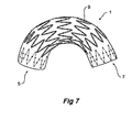
- Fig. 7 shows a stent graft of the embodiment shown in Fig. 1 to show the amount of bending which is possible in the stent graft for placement in the thoracic arch of a patient.
- the internal radius of curvature of the stent graft according to this invention may be any radius greater than 35 mm. This can be achieved by having the stents longitudinally spaced apart by between five to ten millimetres as discussed earlier and so far as possible staggering the placement of apices of adjacent stents. This may not be possible where adjacent stents have different numbers of struts.
- FIG. 8 shows features of a sealing stent that may be present in any of the above embodiments.
- a stent graft 70 has a graft material body 72 and an internal sealing stent 74 joined to the graft material by stitching 78, also referred to as fastenings.
- Stent 74 is a zigzag stent having struts 75 with bends 76 at each end of the struts. Affixed to at least some of the struts 75 are barbs 73 which extend distally from the struts through the graft material.
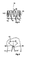
- Fig. 9 shows features of a distally extending exposed zigzag stent used in the embodiments shown in Figs. 3 to 6 .
- the struts 79 and bend 82 of the stent are on the inside of the graft material 72.
- At least two fastenings 80 and 81 are used to fasten the stent 83 to the graft material 72.
- the first fastening 80 is positioned at the apex of the bend 82
- a second fastening 81 is positioned spaced apart adjacent the transition from the bend 82 to the struts 79 of the stent.
- the second fastening 81 can be positioned on either strut 79 extending from the bend 82 in a region extending up to an angle of 50° either side of the first fastening 80 measured around the radius of the bend from the apex of the bend 82. Generally the second fastening 81 is spaced from the first fastening 80 by 0.5 to 2 mm.
- the spaced apart fastenings are preferably present at the proximal bends of the distally extending stent 34 of Figs. 3 and 4 , and the distally extending stent of Figs. 5 and 6 .
Abstract
Description
- This invention relates to the field of medical devices and more particularly to vascular devices.
- Throughout this specification the term distal with respect to a portion of the aorta, a deployment device or a prosthesis is intended to refer to the end of the aorta, deployment device or prosthesis further away in the direction of blood flow away from the heart and the term proximal is intended to refer to the portion of the aorta, deployment device or end of the prosthesis nearer to the heart. When applied to other vessels corresponding terms such as caudal and cranial should be understood.
- In recent years, endovascular implantable devices have been developed for treatment of aortic aneurysms, wherein the devices are delivered to the treatment site through the vascular system of the patient rather than by open surgery. Such devices generally include a tubular or cylindrical frame work or scaffolding of one or more stents to which is secured a tubular shape of graft material such as woven DACRON polyester (trade mark of E I Dupont de Nemours and Co.), polytetrafluoroethylene (PTFE) and the like. These devices are initially reduced to a small diameter and placed into the leading or proximal end of a catheter delivery system. The delivery system is inserted into the vascular system of the patient such as through a femoral incision. The leading end of the delivery system is maneuvered to the treatment site over a previously positioned guide wire. Through manipulation of control systems that extends to the proximal end of the catheter from the distal end of the system outside the patient, the device is then deployed by holding the device at its location and withdrawing the surrounding sheath, whereafter the stent graft self expands or is expanded through use of a balloon therewith that is expanded. The stent graft becomes anchored in position to healthy vessel wall tissue in the aorta such as by barbs, whereafter the delivery system is then removed leaving the device in position traversing the aneurysm in a manner that channels all blood flow through the stent graft so that no blood flow enters the aneurysm thereafter, such that not only does the aneurysm no longer continue to grow and possibly rupture but the aneurysm actually beings to shrink and commonly disappears entirely.
- For treatment of abdominal aortic aneurysms in particular, bifurcated stent grafts are known wherein a pair of leg sections extend from the end of the stent graft and are disposed in the iliac arteries in the bifurcation of the aorta and iliac arteries, while the opposite end of the stent graft is anchored to the aorta wall adjacenttothe renal arteries, usually by means of an attachmentstent having barbs that penetrate harmlessly into the vessel wall so that blood flow does not displace the stent graft from its precise location. One such bifurcation stent graft is the ZENITH AAA stent graft sold by William A. Cook Australia Pty Ltd., Brisbane, Queensland, Australia, another example is shown in
WO 01/67993 - Another example of such a stent graft is disclosed in
PCT Publication No. WO 98/53761 - However, for an aneurysm that develops in the thoracic arch of the aorta, stent grafts are needed that are deployable to extend along the substantial curvature of the arch without occluding the main branch vessels joined to the aorta along the arch's curve, all of which may be involved in and compromised by the aneurysm.
- The foregoing problems are solved and a technical advance is achieved by a thoracic stent graft as claimed having a tubular biocompatible graft material body with a lumen therethrough and having a proximal end and a distal end, a sealing stent at the proximal end of the tubular body and an anchoring device affixed to the sealing stent.
- The sealing stent is inside the graft material body and the anchoring device extends from the sealing stent and through the graft material body.
- Preferably the anchoring device extends towards a distal end of the tubular body.
- The anchoring device can comprise a plurality of barbs extending distally.
- There can be further included a distal attachment stent affixed to and extending from the distal end of the graft material body and the distal attachment stent can include at least one anchoring device affixed thereto and extending proximally. The at least one anchoring device can be a barb.
- Further included are one or more intermediate stents positioned between the proximal sealing stent and the distal end and at least some of the one or more of the intermediate stents can be on the outside surface of the tubular body.
- Preferably the stents are self-expanding stents such as zigzag self-expanding Z stents.
- Preferably the intermediate stents are spaced apart from five to ten millimeters to allow for bending of the stent graft.
- The graft material can be selected from polyester, expanded polytetrafluoroethylene (ePTFE) or extra-cellular matrix.
- The tubular body can have a length of from 75 to 240 mm and a diameter of from 22 to 42 mm. The tubular body can be substantially cylindrical or have a tapered shape with a different diameter at each end.
- In one embodiment the tubular graft body comprises a first portion and a second portion, the first portion including the sealing stent and the second portion including the distal attachment stent. The first portion can include at least one internal sealing stent at its distal end and the second portion can include at least two internal sealing stents at its proximal end. Preferably the first portion and the second portion have respective lengths to provide at least an overlap of two sealing stents. The first portion and the second portion when assembled together can have a combined length in use of from 150 to 350 mm and a diameter of from 22 to 42 mm.
- In a further form, the invention is said to reside in a thoracic stent graft having a tubular biocompatible graft material body with a lumen therethrough and having a proximal end and a distal end, a sealing stent at the proximal end of the tubular body, a proximal anchoring device affixed to the sealing stent and a distal attachment stent affixed to and extending from the distal end of the graft material body.
- In a still further form, the invention is said to reside in a thoracic stent graft assembly having a proximal first portion and a distal second portion, each of the proximal first portion and distal second portion having a tubular biocompatible graft material body with a lumen therethrough and having a proximal end and a distal end, a sealing stent at the proximal end of the first proximal portion and a proximal anchoring device affixed to the sealing stent and a distal attachment stent affixed to and extending from the distal end of the distal second portion.
- This, then, generally describes the invention, but to assist with understanding, reference will now be made to the accompanying drawings which show preferred embodiments of the invention.
- In the drawings:
-
Fig. 1 shows a first embodiment of stent graft according to the invention; -
Fig. 2 shows a cross-sectional view of the stent graft ofFig. 1 ; -
Fig. 3 shows a second embodiment of the stent graft according to the invention; -
Fig. 4 shows a cross-sectional view of the stent graft shown inFig. 3 ; -
Fig. 5 shows a third embodiment of a stent graft according to this invention; -
Fig. 6 shows a cross-sectional view of the stent graft shown inFig. 5 ; -
Fig. 7 shows the stent graft of one embodiment of the invention flexed to fit around the thoracic arch; -
Fig. 8 shows a cross-sectional view of the proximal end of a stent graft showing a sealing stent; and -
Fig. 9 shows further detail of the fastening shown inFig. 8 . -
U.S. Patent No. 5,387,235 entitled "Expandable Transluminal Graft Prosthesis For Repair Of Aneurysm" discloses apparatus and methods of retaining grafts onto deployment devices. These features and other features disclosed inU.S. Patent No. 5,387,235 could be used with the present invention. -
U.S. Patent No. 5,720,776 entitled "Barb And Expandable Transluminal Graft Prosthesis For Repair of Aneurysm" discloses improved barbs with various forms of mechanical attachment to a stent. These features and other features disclosed inU.S. Patent No. 5,720,776 could be used with the present invention. -
U.S. Patent No. 6,206,931 entitled "Graft Prosthesis Materials" discloses graft prosthesis materials and a method for implanting, transplanting replacing and repairing a part of a patient and particularly the manufacture and use of a purified, collagen based matrix structure removed from a submucosa tissue source. These features and other features disclosed inU.S. Patent No. 6,206,931 could be used with the present invention. -
PCT Patent Publication No. WO 98/53761 PCT Patent Publication No. WO 98/53761 -
PCT Patent Publication No. WO 99/29262 PCT Patent Publication No. WO 99/29262 - PCT Patent Publication No.
WO 03/034948 WO 03/034948 -
U.S. Provisional Patent Application Serial No. 60/392,682, filed June 28, 2002 U.S. Provisional Patent Application Serial No. 60/392,682 could be used with the present invention. -
U.S. Provisional Patent Application Serial No. 60/392,667, filed June 28, 2002 U.S. Provisional Patent Application Serial No. 60/392,667 could be used with the present invention. -
U.S. Provisional Patent Application Serial No. 60/392,599, filed June 28, 2002 U.S. Provisional Patent Application could be used with the present invention.Serial No 60/392,599 -
U.S. Provisional Patent Application Serial No. 60/391,737, filed June 26, 2002 U.S. Provisional Patent Application No. 60/391,737 could be used with the present invention. -
U.S. Provisional Patent Application Serial No. 60/405,367, filed August 23, 2002 U.S. Provisional Patent Application Serial No. 60/405,367 could be used with the present invention. -
U.S. Provisional Patent Application Serial No. 10/322,862, filed December 18,2002 U.S. Provisional Patent Application Serial No. 10/322,862 could be used with the present invention. - Now looking more closely at the drawings and in particular
Figs. 1 and 2 showing external and internal views of a first embodiment of the present invention, it will be seen that astent graft 1 includes atubular body 3 formed from a biocompatible woven or non-woven fabric or other material. The tubular body has aproximal end 5 and adistal end 7. The tubular body may have a diameter in the range of 22 to 42 mm and a length of from 100 to 150 mm. Thestent graft 1 may be tapered, outwardly bulging like a balloon or of constant diameter along its length depending upon the topography of the vasculature. - Along the length of the tubular body, there are a number of self-expanding
zigzag stents 9 such as the well-known Gianturco Z or zigzag stent on the outside of the body. In this embodiment there are fourexternal stents 9 spaced apart by a distance of between 5 to 10 mm. Theexternal stents 9 are joined to the graft material by means of stitching 10 preferably using a monofilament or braided suture material. - At the
proximal end 5 of thestent graft 1 there is provided aninternal zigzag stent 11 which provides a sealing function for the proximal end of the stent graft. The outer surface of thetubular body 3 at theproximal end 5 presents an essentially smooth outer surface which with the assistance of theinternal zigzag stent 11 can engage and seal against the wall of the aorta when it expands and is deployed. Theproximal stent 11 is comprised ofstruts 15 withbends 16 at each end of the struts. Affixed to some of thestruts 15 arebarbs 13 which extend distally from the struts through the graft material. When the stent graft is deployed into a thoracic arch, thebarbs 13 engage and/or penetrate into the wall of the aorta and prevent distal movement of the stent graft caused by pulsating blood flow through the stent graft. - It will be noted that the
stent 11 is joined to the graft material by means of stitching 12 preferably using a monofilament or braided suture material. - At the
distal end 7 of thestent graft 1, there is an internal sealing stent 17 (seeFig. 2 ) which again is fastened to thegraft material body 3 by stitching 19 preferably using a monofilament or braided suture material. The outer surface of thetubular body 3 at thedistal end 7 presents an essentially smooth outer surface which with the assistance of theinternal zigzag stent 17 can engage and seal against the wall of the aorta when it is deployed. - The stent graft shown in
Figs. 1 and 2 may be used for treatment of patients with symptomatic acute or chronic dissections and ruptures in the descending thoracic aorta. -
Figs. 3 and 4 show external and internal views of a second embodiment of the stent graft according to the present invention. In this embodiment, thestent graft 20 has a tubulargraft material body 22 in the same manner as the embodiment shown inFig. 1 withexternal stents 24 spaced along the body with a longitudinal spacing of approximately 5 to 10 mm between the stents. The length of the stent graft may be in the range of 75 to 241 mm and a diameter in the range of 22 to 42 mm in 2 mm increments. - Also in a similar manner to the embodiment shown in
Figs.1 and 2 at theproximal end 26 of the stent graft there is aninternal sealing stent 28 withbarbs 30. - At the
distal end 27 of thestent graft 20, there is also an internal distal sealingstent 32 but in addition, there is a distally extending exposedzigzag stent 34. This distally extending exposedstent 34 hasbarbs 36 on some of its struts and thesebarbs 36 are directed proximally. The distally extending exposedzigzag stent 34 is fastened to the tubulargraft material body 22 by stitching 33. - It will be noted that there are provided at the distal end of the stent graft
radiographic markers 38 to enable correct positioning of the distal end of the stent graft. - Hence, when the stent graft according to this embodiment of the invention is deployed, the
barbs 30 prevent distal migration of the proximal end of the stent graft and thebarbs 36 on the exposedstent 34 prevent proximal migration of the distal end of thestent graft 20. This tendency of distal migration of the distal end and proximal migration of the distal end may occur if the central portion of the stent graft is free within an aneurysm and sideways force on a curved stent graft caused by pulsating blood flow causes sideways movement of the body of the stent graft with the potential for distal movement of the proximal end and proximal movement of the distal end. - The stent graft shown in
Figs. 3 and 4 may be used for endovascular repair ofthoracic aortic aneurysms in the descending thoracic aorta and particularly for treatment of patients with atherosclerotic aneurysms, symptomatic acute or chronic dissections, contained ruptures and growing aneurysms, which result in distal ischaemia. -
Figs. 5 and 6 show external and internal views of a third embodiment of the stent graft according to the present invention. In this embodiment, a thoracic stent graft assembly is formed from afirst portion 50 and asecond portion 52. Thefirst portion 50 is intended to be deployed proximally of thesecond portion 52. Thefirst portion 50 is substantially identical with the stent graft embodiment shown inFigs. 1 and 2 . It has proximal and distal internal sealing stents in a tubular graft body, barbs extending from the proximal sealing stent and external zigzag stents between the proximal and distal sealing stents. - The
second portion 52 is substantially the same as the embodiment shown inFigs. 3 and 4 except that there are twointernal sealing stents proximal end 60 of thesecond portion 52. It will be noted that although thesecond portion 52 is substantially similar to the embodiment shown inFigures 3 and 4 it does not include the distally extending anchoring barbs on the proximal sealingstent 62. - The
proximal end 60 of thesecond portion 52 with the internal sealingstents distal end 58 of thefirst portion 50 or outside thedistal end 58 of thefirst portion 50. - This means that in deploying the stent graft assembly ofthis embodiment of the invention either the first or second portions may be deployed first and the other portion subsequently deployed depending upon the requirements in a particular case.
- In either case it is preferable to have at least two stents overlap and it may be noted that by having this overlap there is at least one stent length of smooth internal surface of one of the portions engaging against a smooth external surface of the other of the portions. By this arrangement, sealing between the first and second portions is possible. Also, by having an overlap of at least two stents, relative movement between the first and second portions is less likely to cause parting of the first and second portions of the thoracic stent graft assembly when it is deployed and pulsating blood flow through the stent graft causes sideways movement of the centre portion of the stent graft as discussed above.
- The stent graft shown in
Figs. 5 and 6 may be used for endovascular repair of thoracic aortic aneurysms in the descending thoracic aorta and particularly for treatment of patients with atherosclerotic aneurysms, symptomatic acute or chronic dissections, contained ruptures and growing aneurysms. The ability to adjust the overall length of the device by providing more or less overlap of the first and second portions (i.e. "tromboning") allows more accurate placement of the proximal and distal sealing stents and the anchoring barbs. -
Fig. 7 shows a stent graft of the embodiment shown inFig. 1 to show the amount of bending which is possible in the stent graft for placement in the thoracic arch of a patient. The internal radius of curvature of the stent graft according to this invention may be any radius greater than 35 mm. This can be achieved by having the stents longitudinally spaced apart by between five to ten millimetres as discussed earlier and so far as possible staggering the placement of apices of adjacent stents. This may not be possible where adjacent stents have different numbers of struts. -
Fig. 8 shows features of a sealing stent that may be present in any of the above embodiments. Astent graft 70 has agraft material body 72 and aninternal sealing stent 74 joined to the graft material by stitching 78, also referred to as fastenings.Stent 74 is a zigzagstent having struts 75 withbends 76 at each end of the struts. Affixed to at least some of thestruts 75 are barbs 73 which extend distally from the struts through the graft material. - As described in
U.S. Provisional Patent Application Serial No. 60/391,737 , where the stent graft is deployed in a blood vessel, blood flow causes a pull on the graft material tube which is resisted by the barbs on the stent. Hence the fastenings of the stent joining the stent to the graft material take the pull on the prosthesis, and these fastenings preferably are sufficiently strong to take that pull. Similarly, the barbs on the exposed stent used on the distal end of the graft material tube resist blood flow pull on the graft material tube. -
Fig. 9 shows features of a distally extending exposed zigzag stent used in the embodiments shown inFigs. 3 to 6 . As can be seen in the detailed views inFig. 9 , the struts 79 and bend 82 of the stent are on the inside of thegraft material 72. At least twofastenings 80 and 81 are used to fasten the stent 83 to thegraft material 72. As shown here, thefirst fastening 80 is positioned at the apex of the bend 82, and a second fastening 81 is positioned spaced apart adjacent the transition from the bend 82 to the struts 79 of the stent. The second fastening 81 can be positioned on either strut 79 extending from the bend 82 in a region extending up to an angle of 50° either side of thefirst fastening 80 measured around the radius of the bend from the apex of the bend 82. Generally the second fastening 81 is spaced from thefirst fastening 80 by 0.5 to 2 mm. - The spaced apart fastenings are preferably present at the proximal bends of the distally extending
stent 34 ofFigs. 3 and 4 , and the distally extending stent ofFigs. 5 and 6 . - Throughout this specification various indications have been given as to the scope of this invention but the invention is not limited to any one of these but may reside in two or more of these combined together. The examples are given for illustration only and not for limitation.
- Throughout this specification and the claims that follow unless the context requires otherwise, the words 'comprise' and 'include' and variations such as 'comprising' and 'including' will be understood to imply the inclusion of a stated integer or group of integers but not the exclusion of any other integer or group of integers.
Claims (15)
- A thoracic stent graft (1) having a tubular bio-compatible graft material body (3) with a lumen therethrough and having a proximal end (5) and a distal end (7) a sealing stent (11) at the proximal end (5) of the tubular body and an anchoring device affixed to the sealing stent (11) wherein the sealing stent (11) is inside the graft material body (3) and the anchoring device comprises a plurality of barbs (13) affixed to and extending from the sealing stent (11) distally through the graft material body, further including one or more intermediate stents (9) positioned between the proximal sealing stent (11) and the distal end (3), characterised in that at least some of the one or more of the intermediate stents (9) are on the outside surface of the tubular body (3).
- A thoracic stent graft as in claim 1 further including a distal attachment stent affixed to and extending from the distal end of the graft material body.
- A thoracic stent graft as in claim 2 wherein the distal attachment stent includes at least one anchoring device affixed thereto and extending proximally.
- A thoracic stent graft as in claim 3 wherein the at east one anchoring device is a barb.
- A thoracic stent graft as in claim 1 wherein the stents are self-expanding stents.
- A thoracic stent graft as in claim 1 wherein the stents are zigzag self-expanding stents.
- A thoracic stent graft as in claim 1 wherein the intermediate stents are spaced apart to allow for bending of the stent graft.
- A thoracic stent graft as in claim 1 wherein the intermediate stents are spaced apart from five to ten millimeters.
- A thoracic stent graft as in claim 1 wherein the graft material is selected from at least one of polyester, expanded polytetrafluoroethylene or extra-cellular matrix.
- A thoracic stent graft as in claim 2 wherein the tubular graft body comprises a first portion and a second portion, the first portion including the sealing stent and the second portion including the distal attachment stent.
- A thoracic stent graft as in claim 10 wherein the first portion includes at least one internal sealing stent at its distal end.
- A thoracic stent graft as in claim 10 wherein the second portion includes at least two internal sealing stents at its proximal end.
- A thoracic stent graft as in claim 10 wherein the first portion and the second portion have respective lengths to provide at least an overlap of two sealing stents.
- A thoracic stent graft as in claim 1 wherein the tubular body has a length of from 75 to 240 mm and a diameter of from 22 to 42 mm.
- A thoracic stent graft as in claim 10 wherein the first portion and the second portion when assembled together have a combined length in use of from 150 to 350 mm and a diameter of from 22 to 42 mm.
Applications Claiming Priority (3)
| Application Number | Priority Date | Filing Date | Title |
|---|---|---|---|
| US39259902P | 2002-06-28 | 2002-06-28 | |
| US392599P | 2002-06-28 | ||
| PCT/US2003/020642 WO2004002370A1 (en) | 2002-06-28 | 2003-06-30 | Thoracic aortic aneurysm stent graft |
Publications (2)
| Publication Number | Publication Date |
|---|---|
| EP1517651A1 EP1517651A1 (en) | 2005-03-30 |
| EP1517651B1 true EP1517651B1 (en) | 2010-05-26 |
Family
ID=30000900
Family Applications (2)
| Application Number | Title | Priority Date | Filing Date |
|---|---|---|---|
| EP03762263A Expired - Lifetime EP1517651B1 (en) | 2002-06-28 | 2003-06-30 | Thoracic aortic aneurysm stent graft |
| EP03762267A Expired - Lifetime EP1517652B1 (en) | 2002-06-28 | 2003-06-30 | Thoracic introducer |
Family Applications After (1)
| Application Number | Title | Priority Date | Filing Date |
|---|---|---|---|
| EP03762267A Expired - Lifetime EP1517652B1 (en) | 2002-06-28 | 2003-06-30 | Thoracic introducer |
Country Status (9)
| Country | Link |
|---|---|
| US (2) | US7611529B2 (en) |
| EP (2) | EP1517651B1 (en) |
| JP (3) | JP4743836B2 (en) |
| AT (2) | ATE468828T1 (en) |
| AU (2) | AU2003258976B2 (en) |
| CA (2) | CA2487131C (en) |
| DE (1) | DE60332733D1 (en) |
| DK (2) | DK1517651T3 (en) |
| WO (2) | WO2004002370A1 (en) |
Families Citing this family (267)
| Publication number | Priority date | Publication date | Assignee | Title |
|---|---|---|---|---|
| US6395019B2 (en) | 1998-02-09 | 2002-05-28 | Trivascular, Inc. | Endovascular graft |
| US20070265563A1 (en) * | 2006-05-11 | 2007-11-15 | Heuser Richard R | Device for treating chronic total occlusion |
| FR2811218B1 (en) | 2000-07-05 | 2003-02-28 | Patrice Suslian | IMPLANTABLE DEVICE FOR CORRECTING URINARY INCONTINENCE |
| GB0025068D0 (en) | 2000-10-12 | 2000-11-29 | Browning Healthcare Ltd | Apparatus and method for treating female urinary incontinence |
| US20060205995A1 (en) | 2000-10-12 | 2006-09-14 | Gyne Ideas Limited | Apparatus and method for treating female urinary incontinence |
| US8167785B2 (en) | 2000-10-12 | 2012-05-01 | Coloplast A/S | Urethral support system |
| GB0108088D0 (en) | 2001-03-30 | 2001-05-23 | Browning Healthcare Ltd | Surgical implant |
| US20100016943A1 (en) | 2001-12-20 | 2010-01-21 | Trivascular2, Inc. | Method of delivering advanced endovascular graft |
| US7147661B2 (en) | 2001-12-20 | 2006-12-12 | Boston Scientific Santa Rosa Corp. | Radially expandable stent |
| ATE468828T1 (en) | 2002-06-28 | 2010-06-15 | Cook Inc | THORACIC AORTIC ANEURYSMA STENT IMPLANT |
| AU2003269934A1 (en) | 2002-08-02 | 2004-02-23 | C.R. Bard, Inc. | Self anchoring sling and introducer system |
| US7550004B2 (en) * | 2002-08-20 | 2009-06-23 | Cook Biotech Incorporated | Endoluminal device with extracellular matrix material and methods |
| EP1545396B1 (en) * | 2002-08-23 | 2008-12-17 | William A. Cook Australia Pty. Ltd. | Composite prosthesis |
| US7300459B2 (en) * | 2002-10-17 | 2007-11-27 | Heuser Richard R | Stent with covering and differential dilation |
| US9125733B2 (en) * | 2003-01-14 | 2015-09-08 | The Cleveland Clinic Foundation | Branched vessel endoluminal device |
| US7166088B2 (en) | 2003-01-27 | 2007-01-23 | Heuser Richard R | Catheter introducer system |
| GB0307082D0 (en) | 2003-03-27 | 2003-04-30 | Gyne Ideas Ltd | Drug delivery device and method |
| WO2004091449A1 (en) * | 2003-04-08 | 2004-10-28 | Cook Incorporated | Intraluminal support device with graft |
| US7279003B2 (en) * | 2003-04-24 | 2007-10-09 | Medtronic Vascular, Inc. | Stent graft tapered spring |
| US7101390B2 (en) * | 2003-05-27 | 2006-09-05 | Scimed Life Systems, Inc. | Staged deployment endograft |
| US8721710B2 (en) * | 2003-08-11 | 2014-05-13 | Hdh Medical Ltd. | Anastomosis system and method |
| US7402141B2 (en) * | 2003-08-27 | 2008-07-22 | Heuser Richard R | Catheter guidewire system using concentric wires |
| US11259945B2 (en) | 2003-09-03 | 2022-03-01 | Bolton Medical, Inc. | Dual capture device for stent graft delivery system and method for capturing a stent graft |
| US7763063B2 (en) | 2003-09-03 | 2010-07-27 | Bolton Medical, Inc. | Self-aligning stent graft delivery system, kit, and method |
| US8292943B2 (en) | 2003-09-03 | 2012-10-23 | Bolton Medical, Inc. | Stent graft with longitudinal support member |
| US11596537B2 (en) | 2003-09-03 | 2023-03-07 | Bolton Medical, Inc. | Delivery system and method for self-centering a proximal end of a stent graft |
| US20070198078A1 (en) | 2003-09-03 | 2007-08-23 | Bolton Medical, Inc. | Delivery system and method for self-centering a Proximal end of a stent graft |
| US8500792B2 (en) | 2003-09-03 | 2013-08-06 | Bolton Medical, Inc. | Dual capture device for stent graft delivery system and method for capturing a stent graft |
| US20080264102A1 (en) | 2004-02-23 | 2008-10-30 | Bolton Medical, Inc. | Sheath Capture Device for Stent Graft Delivery System and Method for Operating Same |
| US9198786B2 (en) | 2003-09-03 | 2015-12-01 | Bolton Medical, Inc. | Lumen repair device with capture structure |
| CA2536923C (en) * | 2003-09-04 | 2012-10-09 | Cook Biotech Incorporated | Extracellular matrix composite materials, and manufacture and use thereof |
| DE202004021942U1 (en) | 2003-09-12 | 2013-05-13 | Vessix Vascular, Inc. | Selectable eccentric remodeling and / or ablation of atherosclerotic material |
| DE602004022842D1 (en) * | 2003-10-10 | 2009-10-08 | Cleveland Clinic Foundation | ENDOLUMINAL PROSTHESIS WITH COMPOUND MODULES |
| WO2005034807A1 (en) | 2003-10-10 | 2005-04-21 | William A. Cook Australia Pty. Ltd | Composite stent graft |
| US8043357B2 (en) | 2003-10-10 | 2011-10-25 | Cook Medical Technologies Llc | Ring stent |
| EP1673038B1 (en) | 2003-10-10 | 2008-04-23 | William A. Cook Australia Pty. Ltd. | Fenestrated stent grafts |
| EP3031425B1 (en) | 2003-10-14 | 2022-03-30 | Cook Medical Technologies LLC | Introducer for an iliac side branch device |
| US7998186B2 (en) | 2003-10-14 | 2011-08-16 | William A. Cook Australia Pty. Ltd. | Introducer for a side branch device |
| IL158960A0 (en) * | 2003-11-19 | 2004-05-12 | Neovasc Medical Ltd | Vascular implant |
| AU2005206200B2 (en) * | 2004-01-20 | 2010-12-09 | Cook Medical Technologies Llc | Multiple stitches for attaching stent to graft |
| US8998973B2 (en) | 2004-03-02 | 2015-04-07 | Boston Scientific Scimed, Inc. | Medical devices including metallic films |
| US8992592B2 (en) | 2004-12-29 | 2015-03-31 | Boston Scientific Scimed, Inc. | Medical devices including metallic films |
| US8591568B2 (en) | 2004-03-02 | 2013-11-26 | Boston Scientific Scimed, Inc. | Medical devices including metallic films and methods for making same |
| US8632580B2 (en) | 2004-12-29 | 2014-01-21 | Boston Scientific Scimed, Inc. | Flexible medical devices including metallic films |
| US7901447B2 (en) | 2004-12-29 | 2011-03-08 | Boston Scientific Scimed, Inc. | Medical devices including a metallic film and at least one filament |
| CA2562463C (en) * | 2004-04-12 | 2014-03-25 | Cook Incorporated | Stent graft repair device |
| GB0411360D0 (en) | 2004-05-21 | 2004-06-23 | Mpathy Medical Devices Ltd | Implant |
| CA2573889C (en) | 2004-06-16 | 2014-02-04 | Cook Incorporated | Thoracic deployment device and stent graft |
| US20090012429A1 (en) * | 2004-08-25 | 2009-01-08 | Heuser Richard R | Catheter guidewire system using concentric wires |
| US8545418B2 (en) | 2004-08-25 | 2013-10-01 | Richard R. Heuser | Systems and methods for ablation of occlusions within blood vessels |
| GB0419954D0 (en) | 2004-09-08 | 2004-10-13 | Advotek Medical Devices Ltd | System for directing therapy |
| US9713730B2 (en) | 2004-09-10 | 2017-07-25 | Boston Scientific Scimed, Inc. | Apparatus and method for treatment of in-stent restenosis |
| US9125667B2 (en) | 2004-09-10 | 2015-09-08 | Vessix Vascular, Inc. | System for inducing desirable temperature effects on body tissue |
| US8396548B2 (en) | 2008-11-14 | 2013-03-12 | Vessix Vascular, Inc. | Selective drug delivery in a lumen |
| US7699883B2 (en) * | 2004-10-25 | 2010-04-20 | Myles Douglas | Vascular graft and deployment system |
| WO2006071243A1 (en) * | 2004-12-29 | 2006-07-06 | Boston Scientific Limited | Medical devices including metallic films and methods for making same |
| US8454678B2 (en) * | 2005-03-19 | 2013-06-04 | Cook Biotech Incorporated | Prosthetic implants including ECM composite material |
| US7854760B2 (en) | 2005-05-16 | 2010-12-21 | Boston Scientific Scimed, Inc. | Medical devices including metallic films |
| US20080109058A1 (en) * | 2005-06-01 | 2008-05-08 | Cook Incorporated | Intraoperative Anastomosis Method |
| US20060276883A1 (en) * | 2005-06-01 | 2006-12-07 | Cook Incorporated | Tapered and distally stented elephant trunk stent graft |
| GB2427554B (en) * | 2005-06-23 | 2007-05-23 | Vascutek Ltd | Aneurysm graft with markers |
| US8202311B2 (en) * | 2005-07-27 | 2012-06-19 | Cook Medical Technologies Llc | Stent/graft device and method for open surgical placement |
| US8864808B2 (en) * | 2005-09-21 | 2014-10-21 | The Cleveland Clinic Foundation | Endoluminal delivery assembly |
| US7399314B2 (en) * | 2005-11-15 | 2008-07-15 | Cordis Corporation | Systems and methods for securing graft material to intraluminal devices |
| WO2007076114A2 (en) * | 2005-12-23 | 2007-07-05 | Cook Incorporated | Prosthesis deployment system |
| AU2007207612B2 (en) * | 2006-01-18 | 2012-02-23 | Cook Incorporated | Endoluminal delivery device |
| US8062321B2 (en) | 2006-01-25 | 2011-11-22 | Pq Bypass, Inc. | Catheter system for connecting adjacent blood vessels |
| US8518098B2 (en) | 2006-02-21 | 2013-08-27 | Cook Medical Technologies Llc | Split sheath deployment system |
| JP5042244B2 (en) * | 2006-02-27 | 2012-10-03 | ウィリアム・エイ・クック・オーストラリア・プロプライエタリー・リミテッド | Combined stent graft introducer and stent graft |
| US8357194B2 (en) * | 2006-03-15 | 2013-01-22 | Cordis Corporation | Stent graft device |
| US9308105B2 (en) * | 2006-04-19 | 2016-04-12 | Cook Medical Technologies Llc | Delivery device for an endoluminal prosthesis |
| CN101484090B (en) * | 2006-04-19 | 2011-04-27 | 威廉A·库克澳大利亚有限公司 | Twin bifurcated stent graft |
| US20130190676A1 (en) | 2006-04-20 | 2013-07-25 | Limflow Gmbh | Devices and methods for fluid flow through body passages |
| US8019435B2 (en) | 2006-05-02 | 2011-09-13 | Boston Scientific Scimed, Inc. | Control of arterial smooth muscle tone |
| US8118853B2 (en) * | 2006-06-19 | 2012-02-21 | Cook Medical Technologies Llc | Prosthesis delivery and deployment device |
| US7722665B2 (en) * | 2006-07-07 | 2010-05-25 | Graft Technologies, Inc. | System and method for providing a graft in a vascular environment |
| EP2043566B1 (en) * | 2006-07-24 | 2010-01-20 | William, a Cook Australia Pty. Ltd. | Medical device introducer with docking arrangement |
| AU2007310986B2 (en) | 2006-10-18 | 2013-07-04 | Boston Scientific Scimed, Inc. | Inducing desirable temperature effects on body tissue |
| AU2007310988B2 (en) | 2006-10-18 | 2013-08-15 | Vessix Vascular, Inc. | Tuned RF energy and electrical tissue characterization for selective treatment of target tissues |
| US8425585B2 (en) * | 2006-10-24 | 2013-04-23 | Cook Medical Technologies Llc | Thoracic arch stent graft and method of delivery |
| US8317856B2 (en) | 2007-03-05 | 2012-11-27 | Endospan Ltd. | Multi-component expandable supportive bifurcated endoluminal grafts and methods for using same |
| US7766953B2 (en) * | 2007-05-16 | 2010-08-03 | Med Institute, Inc. | Deployment system for an expandable stent |
| US9119742B2 (en) * | 2007-07-16 | 2015-09-01 | Cook Medical Technologies Llc | Prosthesis delivery and deployment device |
| JP5364933B2 (en) * | 2007-08-13 | 2013-12-11 | クック・メディカル・テクノロジーズ・リミテッド・ライアビリティ・カンパニー | Placement device |
| US8226701B2 (en) | 2007-09-26 | 2012-07-24 | Trivascular, Inc. | Stent and delivery system for deployment thereof |
| US8663309B2 (en) | 2007-09-26 | 2014-03-04 | Trivascular, Inc. | Asymmetric stent apparatus and method |
| US8066755B2 (en) | 2007-09-26 | 2011-11-29 | Trivascular, Inc. | System and method of pivoted stent deployment |
| CN101917929A (en) | 2007-10-04 | 2010-12-15 | 特里瓦斯库拉尔公司 | Modular vascular graft for low profile percutaneous delivery |
| US9474641B2 (en) * | 2007-10-23 | 2016-10-25 | Cook Medical Technologies Llc | Indwelling catheter arrangement |
| US20090112237A1 (en) | 2007-10-26 | 2009-04-30 | Cook Critical Care Incorporated | Vascular conduit and delivery system for open surgical placement |
| US7972374B2 (en) * | 2007-10-29 | 2011-07-05 | Cleveland Clinic Foundation | Securing rods and modular graft systems |
| US9107741B2 (en) * | 2007-11-01 | 2015-08-18 | Cook Medical Technologies Llc | Flexible stent graft |
| EP2210248B1 (en) * | 2007-11-13 | 2016-04-20 | Cook Medical Technologies LLC | Intraluminal bypass prosthesis |
| US8083789B2 (en) | 2007-11-16 | 2011-12-27 | Trivascular, Inc. | Securement assembly and method for expandable endovascular device |
| US8328861B2 (en) | 2007-11-16 | 2012-12-11 | Trivascular, Inc. | Delivery system and method for bifurcated graft |
| US8486131B2 (en) | 2007-12-15 | 2013-07-16 | Endospan Ltd. | Extra-vascular wrapping for treating aneurysmatic aorta in conjunction with endovascular stent-graft and methods thereof |
| US9226813B2 (en) * | 2007-12-26 | 2016-01-05 | Cook Medical Technologies Llc | Low profile non-symmetrical stent |
| US8574284B2 (en) | 2007-12-26 | 2013-11-05 | Cook Medical Technologies Llc | Low profile non-symmetrical bare alignment stents with graft |
| GB2476451A (en) * | 2009-11-19 | 2011-06-29 | Cook William Europ | Stent Graft |
| GB2475494B (en) | 2009-11-18 | 2011-11-23 | Cook William Europ | Stent graft and introducer assembly |
| US9180030B2 (en) | 2007-12-26 | 2015-11-10 | Cook Medical Technologies Llc | Low profile non-symmetrical stent |
| JP5526038B2 (en) * | 2008-01-17 | 2014-06-18 | ボストン サイエンティフィック サイムド,インコーポレイテッド | Stent with anti-migration feature |
| US8221494B2 (en) | 2008-02-22 | 2012-07-17 | Endologix, Inc. | Apparatus and method of placement of a graft or graft system |
| KR20090108143A (en) * | 2008-04-11 | 2009-10-15 | 주식회사 에스앤지바이오텍 | Stent used in blood vessel |
| US10456554B2 (en) * | 2008-04-17 | 2019-10-29 | W. L. Gore & Associates, Inc. | Device delivery catheter having a curved distal tip |
| US20090264898A1 (en) * | 2008-04-17 | 2009-10-22 | Medtronic Vascular, Inc. | Steerable Endovascular Retrieval Device |
| US20100305686A1 (en) * | 2008-05-15 | 2010-12-02 | Cragg Andrew H | Low-profile modular abdominal aortic aneurysm graft |
| JP5484458B2 (en) | 2008-06-30 | 2014-05-07 | ボルトン メディカル インコーポレイテッド | Abdominal aortic aneurysm system |
| KR100958578B1 (en) * | 2008-07-16 | 2010-05-18 | 주식회사 에스앤지바이오텍 | Stent used in blood vessel |
| CN102137644B (en) * | 2008-07-18 | 2014-07-16 | 库克医学技术有限责任公司 | Introducer for endovascular implants |
| US8845715B2 (en) * | 2008-08-18 | 2014-09-30 | Hisham M. F. SHERIF | Total aortic arch reconstruction graft |
| JP5526311B2 (en) * | 2008-08-26 | 2014-06-18 | クック メディカル テクノロジーズ エルエルシー | Thorax guide |
| GB2464977B (en) * | 2008-10-31 | 2010-11-03 | William Cook Europe As | Introducer for deploying a stent graft in a curved lumen and stent graft therefor |
| GB2464978B (en) * | 2008-10-31 | 2010-10-20 | Cook William Europ | Introducer for deploying a stent graft in a curved lumen |
| US11376114B2 (en) | 2008-10-31 | 2022-07-05 | Cook Medical Technologies Llc | Introducer for deploying a stent graft in a curved lumen and stent graft therefor |
| AU2009314133B2 (en) | 2008-11-17 | 2015-12-10 | Vessix Vascular, Inc. | Selective accumulation of energy with or without knowledge of tissue topography |
| US8734502B2 (en) | 2008-12-17 | 2014-05-27 | Cook Medical Technologies Llc | Tapered stent and flexible prosthesis |
| AU2009200350B1 (en) * | 2009-02-02 | 2009-07-16 | Cook Incorporated | Preloaded stent graft delivery device |
| CN106551740B (en) | 2009-03-13 | 2020-03-27 | 波顿医疗公司 | System and method for deploying an endoluminal prosthesis at a surgical site |
| US9089445B2 (en) | 2009-04-27 | 2015-07-28 | Cook Medical Technologies Llc | Stent with protected barbs |
| EP2429452B1 (en) | 2009-04-28 | 2020-01-15 | Endologix, Inc. | Endoluminal prosthesis system |
| US8858613B2 (en) | 2010-09-20 | 2014-10-14 | Altura Medical, Inc. | Stent graft delivery systems and associated methods |
| CA2961767C (en) | 2009-06-23 | 2018-08-14 | Endospan Ltd. | Vascular prostheses for treating aneurysms |
| WO2011004374A1 (en) | 2009-07-09 | 2011-01-13 | Endospan Ltd. | Apparatus for closure of a lumen and methods of using the same |
| JP5651183B2 (en) | 2009-10-13 | 2015-01-07 | クック メディカル テクノロジーズ エルエルシーCook Medical Technologies Llc | Paraplegia preventive stent graft |
| US9095456B2 (en) | 2009-10-13 | 2015-08-04 | Cook Medical Technologies Llc | Paraplegia prevention stent graft |
| US9757263B2 (en) | 2009-11-18 | 2017-09-12 | Cook Medical Technologies Llc | Stent graft and introducer assembly |
| WO2011064782A2 (en) | 2009-11-30 | 2011-06-03 | Endospan Ltd. | Multi-component stent-graft system for implantation in a blood vessel with multiple branches |
| EP2559404A3 (en) * | 2009-12-01 | 2014-10-29 | Altura Medical, Inc. | Modular endograft devices and associated systems and methods |
| EP2509535B1 (en) | 2009-12-08 | 2016-12-07 | Endospan Ltd | Endovascular stent-graft system with fenestrated and crossing stent-grafts |
| EP2519166A4 (en) | 2009-12-31 | 2017-06-14 | Endospan Ltd | Endovascular flow direction indicator |
| CA2789304C (en) | 2010-02-08 | 2018-01-02 | Endospan Ltd. | Thermal energy application for prevention and management of endoleaks in stent-grafts |
| KR20130108067A (en) | 2010-04-09 | 2013-10-02 | 베식스 바스큘라 인코포레이티드 | Power generating and control apparatus for the treatment of tissue |
| US9192790B2 (en) | 2010-04-14 | 2015-11-24 | Boston Scientific Scimed, Inc. | Focused ultrasonic renal denervation |
| US8473067B2 (en) | 2010-06-11 | 2013-06-25 | Boston Scientific Scimed, Inc. | Renal denervation and stimulation employing wireless vascular energy transfer arrangement |
| US9408661B2 (en) | 2010-07-30 | 2016-08-09 | Patrick A. Haverkost | RF electrodes on multiple flexible wires for renal nerve ablation |
| US9084609B2 (en) | 2010-07-30 | 2015-07-21 | Boston Scientific Scime, Inc. | Spiral balloon catheter for renal nerve ablation |
| US9155589B2 (en) | 2010-07-30 | 2015-10-13 | Boston Scientific Scimed, Inc. | Sequential activation RF electrode set for renal nerve ablation |
| US9358365B2 (en) | 2010-07-30 | 2016-06-07 | Boston Scientific Scimed, Inc. | Precision electrode movement control for renal nerve ablation |
| US9463062B2 (en) | 2010-07-30 | 2016-10-11 | Boston Scientific Scimed, Inc. | Cooled conductive balloon RF catheter for renal nerve ablation |
| CA2747610C (en) | 2010-08-13 | 2014-09-16 | Cook Medical Technologies Llc | Precannulated fenestration |
| AU2015202398B2 (en) * | 2010-08-13 | 2017-01-19 | Cook Medical Technologies Llc | Precannulated fenestration |
| US9101455B2 (en) | 2010-08-13 | 2015-08-11 | Cook Medical Technologies Llc | Preloaded wire for endoluminal device |
| US8974451B2 (en) | 2010-10-25 | 2015-03-10 | Boston Scientific Scimed, Inc. | Renal nerve ablation using conductive fluid jet and RF energy |
| US9220558B2 (en) | 2010-10-27 | 2015-12-29 | Boston Scientific Scimed, Inc. | RF renal denervation catheter with multiple independent electrodes |
| US9788933B2 (en) | 2010-10-29 | 2017-10-17 | Cook Medical Technologies Llc | Medical device delivery system and deployment method |
| EP2635241B1 (en) | 2010-11-02 | 2019-02-20 | Endologix, Inc. | Apparatus for placement of a graft or graft system |
| US9028485B2 (en) | 2010-11-15 | 2015-05-12 | Boston Scientific Scimed, Inc. | Self-expanding cooling electrode for renal nerve ablation |
| US9668811B2 (en) | 2010-11-16 | 2017-06-06 | Boston Scientific Scimed, Inc. | Minimally invasive access for renal nerve ablation |
| US9089350B2 (en) | 2010-11-16 | 2015-07-28 | Boston Scientific Scimed, Inc. | Renal denervation catheter with RF electrode and integral contrast dye injection arrangement |
| US9566149B2 (en) | 2010-11-16 | 2017-02-14 | W. L. Gore & Associates, Inc. | Devices and methods for in situ fenestration of a stent-graft at the site of a branch vessel |
| US9326751B2 (en) | 2010-11-17 | 2016-05-03 | Boston Scientific Scimed, Inc. | Catheter guidance of external energy for renal denervation |
| US9060761B2 (en) | 2010-11-18 | 2015-06-23 | Boston Scientific Scime, Inc. | Catheter-focused magnetic field induced renal nerve ablation |
| US9023034B2 (en) | 2010-11-22 | 2015-05-05 | Boston Scientific Scimed, Inc. | Renal ablation electrode with force-activatable conduction apparatus |
| US9192435B2 (en) | 2010-11-22 | 2015-11-24 | Boston Scientific Scimed, Inc. | Renal denervation catheter with cooled RF electrode |
| US20120157993A1 (en) | 2010-12-15 | 2012-06-21 | Jenson Mark L | Bipolar Off-Wall Electrode Device for Renal Nerve Ablation |
| WO2012100095A1 (en) | 2011-01-19 | 2012-07-26 | Boston Scientific Scimed, Inc. | Guide-compatible large-electrode catheter for renal nerve ablation with reduced arterial injury |
| CA2826022A1 (en) | 2011-02-03 | 2012-08-09 | Endospan Ltd. | Implantable medical devices constructed of shape memory material |
| WO2012111006A1 (en) | 2011-02-17 | 2012-08-23 | Endospan Ltd. | Vascular bands and delivery systems therefor |
| WO2012117395A1 (en) | 2011-03-02 | 2012-09-07 | Endospan Ltd. | Reduced-strain extra- vascular ring for treating aortic aneurysm |
| EP3583916B1 (en) | 2011-04-28 | 2023-12-06 | Cook Medical Technologies LLC | Apparatus for facilitating deployment of an endoluminal prosthesis |
| US9381078B2 (en) | 2011-04-29 | 2016-07-05 | The Cleveland Clinic Foundation | Power and/or signal trigger wire for an endovascular delivery system |
| US9005267B2 (en) | 2011-04-29 | 2015-04-14 | Cleveland Clinic Foundation | Rotational alignment wire system for an endovascular delivery system |
| US8574287B2 (en) | 2011-06-14 | 2013-11-05 | Endospan Ltd. | Stents incorporating a plurality of strain-distribution locations |
| ES2568377T3 (en) | 2011-06-21 | 2016-04-28 | Endospan Ltd | Endovascular system with circumferentially overlapping stents |
| EP2729095B1 (en) | 2011-07-07 | 2016-10-26 | Endospan Ltd. | Stent fixation with reduced plastic deformation |
| CN103813745B (en) | 2011-07-20 | 2016-06-29 | 波士顿科学西美德公司 | In order to visualize, be directed at and to melt transcutaneous device and the method for nerve |
| JP6106669B2 (en) | 2011-07-22 | 2017-04-05 | ボストン サイエンティフィック サイムド,インコーポレイテッドBoston Scientific Scimed,Inc. | A neuromodulation system having a neuromodulation element that can be placed in a helical guide |
| WO2013030818A2 (en) | 2011-08-28 | 2013-03-07 | Endospan Ltd. | Stent-grafts with post-deployment variable axial and radial displacement |
| US9662196B2 (en) | 2011-09-27 | 2017-05-30 | Cook Medical Technologies Llc | Endoluminal prosthesis with steerable branch |
| WO2013055826A1 (en) | 2011-10-10 | 2013-04-18 | Boston Scientific Scimed, Inc. | Medical devices including ablation electrodes |
| US9420955B2 (en) | 2011-10-11 | 2016-08-23 | Boston Scientific Scimed, Inc. | Intravascular temperature monitoring system and method |
| US10085799B2 (en) | 2011-10-11 | 2018-10-02 | Boston Scientific Scimed, Inc. | Off-wall electrode device and methods for nerve modulation |
| US9364284B2 (en) | 2011-10-12 | 2016-06-14 | Boston Scientific Scimed, Inc. | Method of making an off-wall spacer cage |
| EP2768568B1 (en) | 2011-10-18 | 2020-05-06 | Boston Scientific Scimed, Inc. | Integrated crossing balloon catheter |
| WO2013058962A1 (en) | 2011-10-18 | 2013-04-25 | Boston Scientific Scimed, Inc. | Deflectable medical devices |
| WO2013065040A1 (en) | 2011-10-30 | 2013-05-10 | Endospan Ltd. | Triple-collar stent-graft |
| EP2775948B1 (en) | 2011-11-08 | 2018-04-04 | Boston Scientific Scimed, Inc. | Ostial renal nerve ablation |
| US8728148B2 (en) | 2011-11-09 | 2014-05-20 | Cook Medical Technologies Llc | Diameter reducing tie arrangement for endoluminal prosthesis |
| US9119600B2 (en) | 2011-11-15 | 2015-09-01 | Boston Scientific Scimed, Inc. | Device and methods for renal nerve modulation monitoring |
| US9681939B2 (en) | 2011-11-18 | 2017-06-20 | Cook Medical Technologies Llc | Silane bonded medical devices and method of making same |
| US9119632B2 (en) | 2011-11-21 | 2015-09-01 | Boston Scientific Scimed, Inc. | Deflectable renal nerve ablation catheter |
| WO2013084235A2 (en) | 2011-12-04 | 2013-06-13 | Endospan Ltd. | Branched stent-graft system |
| US9265969B2 (en) | 2011-12-21 | 2016-02-23 | Cardiac Pacemakers, Inc. | Methods for modulating cell function |
| EP2606851B1 (en) | 2011-12-22 | 2015-11-04 | Cook Medical Technologies LLC | Preloaded wire for endoluminal device |
| WO2013096916A2 (en) | 2011-12-23 | 2013-06-27 | Vessix Vascular, Inc. | Methods and apparatuses for remodeling tissue of or adjacent to a body passage |
| US9433760B2 (en) | 2011-12-28 | 2016-09-06 | Boston Scientific Scimed, Inc. | Device and methods for nerve modulation using a novel ablation catheter with polymeric ablative elements |
| US9050106B2 (en) | 2011-12-29 | 2015-06-09 | Boston Scientific Scimed, Inc. | Off-wall electrode device and methods for nerve modulation |
| US8992595B2 (en) | 2012-04-04 | 2015-03-31 | Trivascular, Inc. | Durable stent graft with tapered struts and stable delivery methods and devices |
| US9498363B2 (en) | 2012-04-06 | 2016-11-22 | Trivascular, Inc. | Delivery catheter for endovascular device |
| EP3141223A1 (en) | 2012-04-12 | 2017-03-15 | Bolton Medical, Inc. | Vascular prosthetic delivery device |
| US10660703B2 (en) | 2012-05-08 | 2020-05-26 | Boston Scientific Scimed, Inc. | Renal nerve modulation devices |
| WO2013171730A1 (en) | 2012-05-15 | 2013-11-21 | Endospan Ltd. | Stent-graft with fixation elements that are radially confined for delivery |
| AU2013299425A1 (en) | 2012-08-10 | 2015-03-19 | Altura Medical, Inc. | Stent delivery systems and associated methods |
| US10321946B2 (en) | 2012-08-24 | 2019-06-18 | Boston Scientific Scimed, Inc. | Renal nerve modulation devices with weeping RF ablation balloons |
| US9173696B2 (en) | 2012-09-17 | 2015-11-03 | Boston Scientific Scimed, Inc. | Self-positioning electrode system and method for renal nerve modulation |
| US10398464B2 (en) | 2012-09-21 | 2019-09-03 | Boston Scientific Scimed, Inc. | System for nerve modulation and innocuous thermal gradient nerve block |
| US10549127B2 (en) | 2012-09-21 | 2020-02-04 | Boston Scientific Scimed, Inc. | Self-cooling ultrasound ablation catheter |
| CN104869930B (en) | 2012-10-10 | 2020-12-25 | 波士顿科学国际有限公司 | Renal neuromodulation apparatus and methods |
| US9913740B2 (en) | 2012-10-25 | 2018-03-13 | W. L. Gore & Associates, Inc. | Stent with varying cross-section |
| EP2745813A1 (en) | 2012-12-18 | 2014-06-25 | Cook Medical Technologies LLC | Preloaded wire for endoluminal device |
| US9622893B2 (en) | 2012-12-20 | 2017-04-18 | Cook Medical Technologies Llc | Apparatus and method for improved deployment of endovascular grafts |
| US9993360B2 (en) | 2013-01-08 | 2018-06-12 | Endospan Ltd. | Minimization of stent-graft migration during implantation |
| US10835367B2 (en) | 2013-03-08 | 2020-11-17 | Limflow Gmbh | Devices for fluid flow through body passages |
| JP6609479B2 (en) | 2013-03-08 | 2019-11-20 | リムフロウ・ゲゼルシャフト・ミット・ベシュレンクテル・ハフツング | Method and system for providing or maintaining fluid flow through a body passage |
| US9693821B2 (en) | 2013-03-11 | 2017-07-04 | Boston Scientific Scimed, Inc. | Medical devices for modulating nerves |
| US9956033B2 (en) | 2013-03-11 | 2018-05-01 | Boston Scientific Scimed, Inc. | Medical devices for modulating nerves |
| US9668892B2 (en) | 2013-03-11 | 2017-06-06 | Endospan Ltd. | Multi-component stent-graft system for aortic dissections |
| US9808311B2 (en) | 2013-03-13 | 2017-11-07 | Boston Scientific Scimed, Inc. | Deflectable medical devices |
| US9545324B2 (en) | 2013-03-13 | 2017-01-17 | Cook Medical Technologies Llc | Pre-loaded iliac branch device and methods of deployment |
| US10265122B2 (en) | 2013-03-15 | 2019-04-23 | Boston Scientific Scimed, Inc. | Nerve ablation devices and related methods of use |
| US9439751B2 (en) | 2013-03-15 | 2016-09-13 | Bolton Medical, Inc. | Hemostasis valve and delivery systems |
| US9297845B2 (en) | 2013-03-15 | 2016-03-29 | Boston Scientific Scimed, Inc. | Medical devices and methods for treatment of hypertension that utilize impedance compensation |
| EP2967734B1 (en) | 2013-03-15 | 2019-05-15 | Boston Scientific Scimed, Inc. | Methods and apparatuses for remodeling tissue of or adjacent to a body passage |
| WO2014144809A1 (en) | 2013-03-15 | 2014-09-18 | Altura Medical, Inc. | Endograft device delivery systems and associated methods |
| EP3010437A1 (en) | 2013-06-21 | 2016-04-27 | Boston Scientific Scimed, Inc. | Renal denervation balloon catheter with ride along electrode support |
| CN105473092B (en) | 2013-06-21 | 2019-05-17 | 波士顿科学国际有限公司 | The medical instrument for renal nerve ablation with rotatable shaft |
| US9707036B2 (en) | 2013-06-25 | 2017-07-18 | Boston Scientific Scimed, Inc. | Devices and methods for nerve modulation using localized indifferent electrodes |
| WO2015002787A1 (en) | 2013-07-01 | 2015-01-08 | Boston Scientific Scimed, Inc. | Medical devices for renal nerve ablation |
| WO2015006480A1 (en) | 2013-07-11 | 2015-01-15 | Boston Scientific Scimed, Inc. | Devices and methods for nerve modulation |
| EP3019106A1 (en) | 2013-07-11 | 2016-05-18 | Boston Scientific Scimed, Inc. | Medical device with stretchable electrode assemblies |
| WO2015010074A1 (en) | 2013-07-19 | 2015-01-22 | Boston Scientific Scimed, Inc. | Spiral bipolar electrode renal denervation balloon |
| US10695124B2 (en) | 2013-07-22 | 2020-06-30 | Boston Scientific Scimed, Inc. | Renal nerve ablation catheter having twist balloon |
| WO2015013205A1 (en) | 2013-07-22 | 2015-01-29 | Boston Scientific Scimed, Inc. | Medical devices for renal nerve ablation |
| WO2015027096A1 (en) | 2013-08-22 | 2015-02-26 | Boston Scientific Scimed, Inc. | Flexible circuit having improved adhesion to a renal nerve modulation balloon |
| EP3041425B1 (en) | 2013-09-04 | 2022-04-13 | Boston Scientific Scimed, Inc. | Radio frequency (rf) balloon catheter having flushing and cooling capability |
| WO2015038947A1 (en) | 2013-09-13 | 2015-03-19 | Boston Scientific Scimed, Inc. | Ablation balloon with vapor deposited cover layer |
| US11246654B2 (en) | 2013-10-14 | 2022-02-15 | Boston Scientific Scimed, Inc. | Flexible renal nerve ablation devices and related methods of use and manufacture |
| CN105592778B (en) | 2013-10-14 | 2019-07-23 | 波士顿科学医学有限公司 | High-resolution cardiac mapping electrod-array conduit |
| US9770606B2 (en) | 2013-10-15 | 2017-09-26 | Boston Scientific Scimed, Inc. | Ultrasound ablation catheter with cooling infusion and centering basket |
| AU2014334574B2 (en) | 2013-10-15 | 2017-07-06 | Boston Scientific Scimed, Inc. | Medical device balloon |
| CN105636538B (en) | 2013-10-18 | 2019-01-15 | 波士顿科学国际有限公司 | Foley's tube with flexible wire and its correlation technique for using and manufacturing |
| CN105658163B (en) | 2013-10-25 | 2020-08-18 | 波士顿科学国际有限公司 | Embedded thermocouple in denervation flexible circuit |
| WO2015075708A1 (en) | 2013-11-19 | 2015-05-28 | Endospan Ltd. | Stent system with radial-expansion locking |
| WO2015103617A1 (en) | 2014-01-06 | 2015-07-09 | Boston Scientific Scimed, Inc. | Tear resistant flex circuit assembly |
| US11000679B2 (en) | 2014-02-04 | 2021-05-11 | Boston Scientific Scimed, Inc. | Balloon protection and rewrapping devices and related methods of use |
| JP6325121B2 (en) | 2014-02-04 | 2018-05-16 | ボストン サイエンティフィック サイムド,インコーポレイテッドBoston Scientific Scimed,Inc. | Alternative placement of temperature sensors on bipolar electrodes |
| US9545263B2 (en) | 2014-06-19 | 2017-01-17 | Limflow Gmbh | Devices and methods for treating lower extremity vasculature |
| US10959826B2 (en) | 2014-10-16 | 2021-03-30 | Cook Medical Technology LLC | Support structure for scalloped grafts |
| CA2967904C (en) | 2014-12-18 | 2023-01-10 | Endospan Ltd. | Endovascular stent-graft with fatigue-resistant lateral tube |
| US10219891B2 (en) * | 2015-02-18 | 2019-03-05 | Medtronic Vascular, Inc. | Stent-graft prostheses having a stitch path that permits relative movement between a stent and a tubular graft |
| US10426646B2 (en) | 2015-03-05 | 2019-10-01 | Cook Medical Technologies Llc | Pre-loaded delivery device with tri-fold proximal prosthesis attachment |
| US10478591B2 (en) | 2015-03-05 | 2019-11-19 | Cook Medical Technologies Llc | Stent graft delivery device pre-loaded with a single wire for device tracking and cannulation |
| JP2018524025A (en) | 2015-06-30 | 2018-08-30 | エンドロジックス、インク | Lock assembly for coupling guidewire to delivery system |
| US10335301B2 (en) * | 2015-09-01 | 2019-07-02 | Cook Medical Technologies Llc | Modular handle comprising a trigger wire actuation mechanism for a prosthesis delivery device |
| US10188538B2 (en) | 2015-12-30 | 2019-01-29 | Cook Medical Technologies Llc | Hybrid trigger wire for endografts |
| US10610393B2 (en) | 2016-03-24 | 2020-04-07 | Cook Medical Technologies Llc | Wire retention and release mechanisms |
| EP3439583B1 (en) * | 2016-04-05 | 2020-09-09 | Bolton Medical, Inc. | Stent graft with internal tunnels and fenestrations |
| US10772751B2 (en) | 2016-09-09 | 2020-09-15 | Cook Medical Technologies Llc | Fenestrated endoluminal prosthesis and system and method of deployment thereof |
| US10537419B2 (en) | 2016-10-27 | 2020-01-21 | Cook Medical Technologies Llc | Prosthesis with branched portion |
| US10646324B2 (en) | 2017-01-31 | 2020-05-12 | Cook Medical Technologies, LLC | Bifurcated stent graft with hemodynamic blood flow dividing wall |
| EP3372202B1 (en) | 2017-03-09 | 2022-04-06 | Cook Medical Technologies LLC | Low profile stent delivery system and method |
| US10940030B2 (en) | 2017-03-10 | 2021-03-09 | Serenity Medical, Inc. | Method and system for delivering a self-expanding stent to the venous sinuses |
| EP4299086A2 (en) | 2017-04-10 | 2024-01-03 | LimFlow GmbH | Devices for treating lower extremity vasculature |
| US10709541B2 (en) | 2017-04-28 | 2020-07-14 | Cook Medical Technologies Llc | Systems and methods for adjusting the diameter of an endoluminal prosthesis and an endoluminal prosthesis configured for the same |
| US10441221B2 (en) | 2017-06-26 | 2019-10-15 | Cook Medical Technologies Llc | Graft prosthesis with pocket for microsystem |
| US11096810B2 (en) | 2017-11-29 | 2021-08-24 | Cook Medical Technologies Llc | Preloaded pusher tip for endografts |
| US11291570B2 (en) | 2018-04-27 | 2022-04-05 | Cook Medical Technologies Llc | Hybrid stent and delivery system |
| EP3830239A1 (en) | 2018-08-16 | 2021-06-09 | TERUMO Kabushiki Kaisha | Cell culture substrate |
| WO2020076833A1 (en) | 2018-10-09 | 2020-04-16 | Limflow Gmbh | Devices and methods for catheter alignment |
| US11911272B2 (en) | 2019-01-18 | 2024-02-27 | W. L. Gore & Associates, Inc. | Bioabsorbable medical devices |
| WO2020264417A1 (en) | 2019-06-28 | 2020-12-30 | Theodosios Alexander | Removable mechanical circulatory support for short term use |
| EP4051174A4 (en) | 2019-11-01 | 2023-11-22 | LimFlow GmbH | Devices and methods for increasing blood perfusion to a distal extremity |
| RU2742451C1 (en) * | 2020-03-04 | 2021-02-05 | Заза Александрович Кавтеладзе | Bifurcation stent-graft system for treating aneurism of abdominal aorta and method of treating aneurism of abdominal aorta using thereof |
| US11478371B2 (en) * | 2020-04-20 | 2022-10-25 | Exovitra LLC | Methods and systems for treatment of aneurysms |
| GB2605559B (en) | 2021-01-07 | 2023-04-05 | Cook Medical Technologies Llc | Stent graft |
| US20230381492A1 (en) * | 2021-11-16 | 2023-11-30 | Theodosios Alexander | Collapsing mechanical circulatory support device for temporary use |
Family Cites Families (33)
| Publication number | Priority date | Publication date | Assignee | Title |
|---|---|---|---|---|
| US2907321A (en) * | 1956-04-04 | 1959-10-06 | Nat Electric Instr Co Inc | Obturating means for endoscopic sheaths |
| US5693083A (en) | 1983-12-09 | 1997-12-02 | Endovascular Technologies, Inc. | Thoracic graft and delivery catheter |
| US5104399A (en) * | 1986-12-10 | 1992-04-14 | Endovascular Technologies, Inc. | Artificial graft and implantation method |
| US4665918A (en) * | 1986-01-06 | 1987-05-19 | Garza Gilbert A | Prosthesis system and method |
| US5147334A (en) * | 1991-01-02 | 1992-09-15 | Moss James P | Catheter for cholangiography |
| US5720776A (en) * | 1991-10-25 | 1998-02-24 | Cook Incorporated | Barb and expandable transluminal graft prosthesis for repair of aneurysm |
| US5387235A (en) | 1991-10-25 | 1995-02-07 | Cook Incorporated | Expandable transluminal graft prosthesis for repair of aneurysm |
| IL108455A (en) * | 1993-01-27 | 1997-04-15 | Instent Inc | Vascular and coronary stents |
| AU689094B2 (en) * | 1993-04-22 | 1998-03-26 | C.R. Bard Inc. | Non-migrating vascular prosthesis and minimally invasive placement system therefor |
| EP0630617B1 (en) * | 1993-06-24 | 1998-09-02 | Schneider (Europe) GmbH | Suction catheter assembly |
| CA2125258C (en) * | 1993-08-05 | 1998-12-22 | Dinah B Quiachon | Multicapsule intraluminal grafting system and method |
| EP0657147B1 (en) * | 1993-11-04 | 1999-08-04 | C.R. Bard, Inc. | Non-migrating vascular prosthesis |
| US5662675A (en) * | 1995-02-24 | 1997-09-02 | Intervascular, Inc. | Delivery catheter assembly |
| ATE314022T1 (en) * | 1995-06-01 | 2006-01-15 | Meadox Medicals Inc | IMPLANTABLE INTRALUMINAL PROSTHESIS |
| JP5053470B2 (en) * | 1996-08-23 | 2012-10-17 | クック バイオテク インコーポレイティド | Graft prosthesis and materials and methods thereof |
| US5776142A (en) * | 1996-12-19 | 1998-07-07 | Medtronic, Inc. | Controllable stent delivery system and method |
| AUPO700897A0 (en) | 1997-05-26 | 1997-06-19 | William A Cook Australia Pty Ltd | A method and means of deploying a graft |
| EP1625833A3 (en) * | 1997-11-25 | 2010-09-22 | TriVascular2, Inc. | Layered endovascular graft |
| AUPP083597A0 (en) | 1997-12-10 | 1998-01-08 | William A Cook Australia Pty Ltd | Endoluminal aortic stents |
| US6183481B1 (en) * | 1999-09-22 | 2001-02-06 | Endomed Inc. | Delivery system for self-expanding stents and grafts |
| US6280466B1 (en) * | 1999-12-03 | 2001-08-28 | Teramed Inc. | Endovascular graft system |
| CA2400072C (en) * | 2000-03-14 | 2010-01-19 | Cook Incorporated | Endovascular stent graft |
| WO2002000288A1 (en) * | 2000-06-26 | 2002-01-03 | Kanji Inoue | Transporting device for transplanting instrument |
| US6699274B2 (en) * | 2001-01-22 | 2004-03-02 | Scimed Life Systems, Inc. | Stent delivery system and method of manufacturing same |
| AUPR847301A0 (en) | 2001-10-26 | 2001-11-15 | Cook Incorporated | Endoluminal prostheses for curved lumens |
| AUPR961701A0 (en) | 2001-12-19 | 2002-01-24 | Cook Incorporated | Improving graft adhesion |
| US6641606B2 (en) * | 2001-12-20 | 2003-11-04 | Cleveland Clinic Foundation | Delivery system and method for deploying an endovascular prosthesis |
| EP1509271B1 (en) | 2002-05-29 | 2005-11-23 | William A. Cook Australia Pty. Ltd. | Trigger wire system for a prosthesis deployment device |
| EP2165675B1 (en) | 2002-06-26 | 2018-03-07 | Cook Medical Technologies LLC | Stent-graft fastening |
| ATE468828T1 (en) | 2002-06-28 | 2010-06-15 | Cook Inc | THORACIC AORTIC ANEURYSMA STENT IMPLANT |
| ATE533436T1 (en) * | 2002-06-28 | 2011-12-15 | Cook Medical Technologies Llc | BREAST INSERTION DEVICE |
| US7722657B2 (en) | 2002-08-23 | 2010-05-25 | William A. Cook Australia Pty. Ltd. | Asymmetric stent graft attachment |
| US7347866B2 (en) * | 2003-03-10 | 2008-03-25 | Boston Scientific Scimed, Inc. | Medical stent and related methods |
-
2003
- 2003-06-30 AT AT03762263T patent/ATE468828T1/en not_active IP Right Cessation
- 2003-06-30 CA CA2487131A patent/CA2487131C/en not_active Expired - Lifetime
- 2003-06-30 EP EP03762263A patent/EP1517651B1/en not_active Expired - Lifetime
- 2003-06-30 JP JP2004518151A patent/JP4743836B2/en not_active Expired - Lifetime
- 2003-06-30 DK DK03762263.6T patent/DK1517651T3/en active
- 2003-06-30 WO PCT/US2003/020642 patent/WO2004002370A1/en active Application Filing
- 2003-06-30 DK DK03762267.7T patent/DK1517652T3/en active
- 2003-06-30 AU AU2003258976A patent/AU2003258976B2/en not_active Expired
- 2003-06-30 JP JP2004518146A patent/JP5108997B2/en not_active Expired - Lifetime
- 2003-06-30 DE DE60332733T patent/DE60332733D1/en not_active Expired - Lifetime
- 2003-06-30 AT AT03762267T patent/ATE536148T1/en active
- 2003-06-30 EP EP03762267A patent/EP1517652B1/en not_active Expired - Lifetime
- 2003-06-30 CA CA2489495A patent/CA2489495C/en not_active Expired - Lifetime
- 2003-06-30 AU AU2003248771A patent/AU2003248771B2/en not_active Expired
- 2003-06-30 WO PCT/US2003/020651 patent/WO2004002371A2/en active Application Filing
- 2003-06-30 US US10/609,842 patent/US7611529B2/en active Active
- 2003-06-30 US US10/609,835 patent/US7232459B2/en active Active
-
2010
- 2010-08-02 JP JP2010173734A patent/JP5621093B2/en not_active Expired - Lifetime
Also Published As
| Publication number | Publication date |
|---|---|
| WO2004002370A1 (en) | 2004-01-08 |
| US7611529B2 (en) | 2009-11-03 |
| DK1517651T3 (en) | 2010-08-02 |
| AU2003258976A1 (en) | 2004-01-19 |
| JP2005537824A (en) | 2005-12-15 |
| EP1517651A1 (en) | 2005-03-30 |
| ATE536148T1 (en) | 2011-12-15 |
| JP4743836B2 (en) | 2011-08-10 |
| JP5621093B2 (en) | 2014-11-05 |
| AU2003248771B2 (en) | 2008-02-07 |
| US7232459B2 (en) | 2007-06-19 |
| EP1517652B1 (en) | 2011-12-07 |
| JP2006506107A (en) | 2006-02-23 |
| EP1517652A2 (en) | 2005-03-30 |
| WO2004002371A2 (en) | 2004-01-08 |
| DE60332733D1 (en) | 2010-07-08 |
| CA2487131A1 (en) | 2004-01-08 |
| AU2003248771A1 (en) | 2004-01-19 |
| WO2004002371A3 (en) | 2004-04-01 |
| ATE468828T1 (en) | 2010-06-15 |
| CA2489495A1 (en) | 2004-01-08 |
| DK1517652T3 (en) | 2012-03-19 |
| JP5108997B2 (en) | 2012-12-26 |
| JP2010269161A (en) | 2010-12-02 |
| CA2489495C (en) | 2010-07-13 |
| AU2003258976B2 (en) | 2008-05-29 |
| US20040106978A1 (en) | 2004-06-03 |
| US20040106974A1 (en) | 2004-06-03 |
| CA2487131C (en) | 2011-04-26 |
Similar Documents
| Publication | Publication Date | Title |
|---|---|---|
| EP1517651B1 (en) | Thoracic aortic aneurysm stent graft | |
| US9095461B2 (en) | Aorta and branch vessel stent grafts and method | |
| EP1788977B1 (en) | Modular prosthesis and method for branch vessels | |
| US7144421B2 (en) | Endovascular prosthesis, system and method | |
| US8506622B2 (en) | Mobile external coupling for branch vessel connection | |
| US8216298B2 (en) | Branch vessel graft method and delivery system | |
| US9011517B2 (en) | Side branch stent graft | |
| EP1765222B1 (en) | Stent graft with internal tube | |
| EP2985007B1 (en) | Preloaded wire for endoluminal device | |
| EP2702960B1 (en) | Endoluminal prosthesis and delivery device |
Legal Events
| Date | Code | Title | Description |
|---|---|---|---|
| PUAI | Public reference made under article 153(3) epc to a published international application that has entered the european phase |
Free format text: ORIGINAL CODE: 0009012 |
|
| 17P | Request for examination filed |
Effective date: 20041213 |
|
| AK | Designated contracting states |
Kind code of ref document: A1 Designated state(s): AT BE BG CH CY CZ DE DK EE ES FI FR GB GR HU IE IT LI LU MC NL PT RO SE SI SK TR |
|
| AX | Request for extension of the european patent |
Extension state: AL LT LV MK |
|
| DAX | Request for extension of the european patent (deleted) | ||
| GRAP | Despatch of communication of intention to grant a patent |
Free format text: ORIGINAL CODE: EPIDOSNIGR1 |
|
| GRAS | Grant fee paid |
Free format text: ORIGINAL CODE: EPIDOSNIGR3 |
|
| GRAA | (expected) grant |
Free format text: ORIGINAL CODE: 0009210 |
|
| AK | Designated contracting states |
Kind code of ref document: B1 Designated state(s): AT BE BG CH CY CZ DE DK EE ES FI FR GB GR HU IE IT LI LU MC NL PT RO SE SI SK TR |
|
| REG | Reference to a national code |
Ref country code: GB Ref legal event code: FG4D |
|
| REG | Reference to a national code |
Ref country code: CH Ref legal event code: EP |
|
| REG | Reference to a national code |
Ref country code: IE Ref legal event code: FG4D |
|
| REF | Corresponds to: |
Ref document number: 60332733 Country of ref document: DE Date of ref document: 20100708 Kind code of ref document: P |
|
| REG | Reference to a national code |
Ref country code: NL Ref legal event code: T3 |
|
| REG | Reference to a national code |
Ref country code: DK Ref legal event code: T3 |
|
| PG25 | Lapsed in a contracting state [announced via postgrant information from national office to epo] |
Ref country code: SE Free format text: LAPSE BECAUSE OF FAILURE TO SUBMIT A TRANSLATION OF THE DESCRIPTION OR TO PAY THE FEE WITHIN THE PRESCRIBED TIME-LIMIT Effective date: 20100526 |
|
| PG25 | Lapsed in a contracting state [announced via postgrant information from national office to epo] |
Ref country code: AT Free format text: LAPSE BECAUSE OF FAILURE TO SUBMIT A TRANSLATION OF THE DESCRIPTION OR TO PAY THE FEE WITHIN THE PRESCRIBED TIME-LIMIT Effective date: 20100526 Ref country code: FI Free format text: LAPSE BECAUSE OF FAILURE TO SUBMIT A TRANSLATION OF THE DESCRIPTION OR TO PAY THE FEE WITHIN THE PRESCRIBED TIME-LIMIT Effective date: 20100526 Ref country code: SI Free format text: LAPSE BECAUSE OF FAILURE TO SUBMIT A TRANSLATION OF THE DESCRIPTION OR TO PAY THE FEE WITHIN THE PRESCRIBED TIME-LIMIT Effective date: 20100526 |
|
| PG25 | Lapsed in a contracting state [announced via postgrant information from national office to epo] |
Ref country code: CY Free format text: LAPSE BECAUSE OF FAILURE TO SUBMIT A TRANSLATION OF THE DESCRIPTION OR TO PAY THE FEE WITHIN THE PRESCRIBED TIME-LIMIT Effective date: 20100526 Ref country code: GR Free format text: LAPSE BECAUSE OF FAILURE TO SUBMIT A TRANSLATION OF THE DESCRIPTION OR TO PAY THE FEE WITHIN THE PRESCRIBED TIME-LIMIT Effective date: 20100827 |
|
| PG25 | Lapsed in a contracting state [announced via postgrant information from national office to epo] |
Ref country code: EE Free format text: LAPSE BECAUSE OF FAILURE TO SUBMIT A TRANSLATION OF THE DESCRIPTION OR TO PAY THE FEE WITHIN THE PRESCRIBED TIME-LIMIT Effective date: 20100526 Ref country code: MC Free format text: LAPSE BECAUSE OF NON-PAYMENT OF DUE FEES Effective date: 20100630 Ref country code: PT Free format text: LAPSE BECAUSE OF FAILURE TO SUBMIT A TRANSLATION OF THE DESCRIPTION OR TO PAY THE FEE WITHIN THE PRESCRIBED TIME-LIMIT Effective date: 20100927 |
|
| REG | Reference to a national code |
Ref country code: CH Ref legal event code: PL |
|
| PG25 | Lapsed in a contracting state [announced via postgrant information from national office to epo] |
Ref country code: SK Free format text: LAPSE BECAUSE OF FAILURE TO SUBMIT A TRANSLATION OF THE DESCRIPTION OR TO PAY THE FEE WITHIN THE PRESCRIBED TIME-LIMIT Effective date: 20100526 Ref country code: BE Free format text: LAPSE BECAUSE OF FAILURE TO SUBMIT A TRANSLATION OF THE DESCRIPTION OR TO PAY THE FEE WITHIN THE PRESCRIBED TIME-LIMIT Effective date: 20100526 Ref country code: CZ Free format text: LAPSE BECAUSE OF FAILURE TO SUBMIT A TRANSLATION OF THE DESCRIPTION OR TO PAY THE FEE WITHIN THE PRESCRIBED TIME-LIMIT Effective date: 20100526 Ref country code: RO Free format text: LAPSE BECAUSE OF FAILURE TO SUBMIT A TRANSLATION OF THE DESCRIPTION OR TO PAY THE FEE WITHIN THE PRESCRIBED TIME-LIMIT Effective date: 20100526 |
|
| PLBE | No opposition filed within time limit |
Free format text: ORIGINAL CODE: 0009261 |
|
| STAA | Information on the status of an ep patent application or granted ep patent |
Free format text: STATUS: NO OPPOSITION FILED WITHIN TIME LIMIT |
|
| PG25 | Lapsed in a contracting state [announced via postgrant information from national office to epo] |
Ref country code: CH Free format text: LAPSE BECAUSE OF NON-PAYMENT OF DUE FEES Effective date: 20100630 Ref country code: LI Free format text: LAPSE BECAUSE OF NON-PAYMENT OF DUE FEES Effective date: 20100630 |
|
| 26N | No opposition filed |
Effective date: 20110301 |
|
| REG | Reference to a national code |
Ref country code: DE Ref legal event code: R097 Ref document number: 60332733 Country of ref document: DE Effective date: 20110228 |
|
| REG | Reference to a national code |
Ref country code: FR Ref legal event code: ST Effective date: 20110228 |
|
| PG25 | Lapsed in a contracting state [announced via postgrant information from national office to epo] |
Ref country code: FR Free format text: LAPSE BECAUSE OF NON-PAYMENT OF DUE FEES Effective date: 20100726 |
|
| REG | Reference to a national code |
Ref country code: GB Ref legal event code: 732E Free format text: REGISTERED BETWEEN 20111110 AND 20111116 |
|
| REG | Reference to a national code |
Ref country code: GB Ref legal event code: 732E Free format text: REGISTERED BETWEEN 20111117 AND 20111123 |
|
| PG25 | Lapsed in a contracting state [announced via postgrant information from national office to epo] |
Ref country code: LU Free format text: LAPSE BECAUSE OF NON-PAYMENT OF DUE FEES Effective date: 20100630 Ref country code: HU Free format text: LAPSE BECAUSE OF FAILURE TO SUBMIT A TRANSLATION OF THE DESCRIPTION OR TO PAY THE FEE WITHIN THE PRESCRIBED TIME-LIMIT Effective date: 20101127 Ref country code: BG Free format text: LAPSE BECAUSE OF FAILURE TO SUBMIT A TRANSLATION OF THE DESCRIPTION OR TO PAY THE FEE WITHIN THE PRESCRIBED TIME-LIMIT Effective date: 20100526 |
|
| PG25 | Lapsed in a contracting state [announced via postgrant information from national office to epo] |
Ref country code: TR Free format text: LAPSE BECAUSE OF FAILURE TO SUBMIT A TRANSLATION OF THE DESCRIPTION OR TO PAY THE FEE WITHIN THE PRESCRIBED TIME-LIMIT Effective date: 20100526 |
|
| PG25 | Lapsed in a contracting state [announced via postgrant information from national office to epo] |
Ref country code: BG Free format text: LAPSE BECAUSE OF FAILURE TO SUBMIT A TRANSLATION OF THE DESCRIPTION OR TO PAY THE FEE WITHIN THE PRESCRIBED TIME-LIMIT Effective date: 20100826 |
|
| PG25 | Lapsed in a contracting state [announced via postgrant information from national office to epo] |
Ref country code: ES Free format text: LAPSE BECAUSE OF FAILURE TO SUBMIT A TRANSLATION OF THE DESCRIPTION OR TO PAY THE FEE WITHIN THE PRESCRIBED TIME-LIMIT Effective date: 20100906 |
|
| PGFP | Annual fee paid to national office [announced via postgrant information from national office to epo] |
Ref country code: NL Payment date: 20220516 Year of fee payment: 20 |
|
| PGFP | Annual fee paid to national office [announced via postgrant information from national office to epo] |
Ref country code: IT Payment date: 20220623 Year of fee payment: 20 Ref country code: IE Payment date: 20220526 Year of fee payment: 20 Ref country code: GB Payment date: 20220526 Year of fee payment: 20 Ref country code: DK Payment date: 20220530 Year of fee payment: 20 Ref country code: DE Payment date: 20220512 Year of fee payment: 20 |
|
| REG | Reference to a national code |
Ref country code: DE Ref legal event code: R071 Ref document number: 60332733 Country of ref document: DE |
|
| REG | Reference to a national code |
Ref country code: DK Ref legal event code: EUP Expiry date: 20230630 |
|
| REG | Reference to a national code |
Ref country code: NL Ref legal event code: MK Effective date: 20230629 |
|
| P01 | Opt-out of the competence of the unified patent court (upc) registered |
Effective date: 20230602 |
|
| REG | Reference to a national code |
Ref country code: GB Ref legal event code: PE20 Expiry date: 20230629 |
|
| REG | Reference to a national code |
Ref country code: IE Ref legal event code: MK9A |
|
| PG25 | Lapsed in a contracting state [announced via postgrant information from national office to epo] |
Ref country code: IE Free format text: LAPSE BECAUSE OF EXPIRATION OF PROTECTION Effective date: 20230630 Ref country code: GB Free format text: LAPSE BECAUSE OF EXPIRATION OF PROTECTION Effective date: 20230629 |