EP1519249A2 - Method for forming fine relief patterns and methods for producing and copying optical diffraction structures - Google Patents
Method for forming fine relief patterns and methods for producing and copying optical diffraction structures Download PDFInfo
- Publication number
- EP1519249A2 EP1519249A2 EP04255662A EP04255662A EP1519249A2 EP 1519249 A2 EP1519249 A2 EP 1519249A2 EP 04255662 A EP04255662 A EP 04255662A EP 04255662 A EP04255662 A EP 04255662A EP 1519249 A2 EP1519249 A2 EP 1519249A2
- Authority
- EP
- European Patent Office
- Prior art keywords
- hologram
- relief
- layer
- fusion layer
- patterns
- Prior art date
- Legal status (The legal status is an assumption and is not a legal conclusion. Google has not performed a legal analysis and makes no representation as to the accuracy of the status listed.)
- Granted
Links
- 238000000034 method Methods 0.000 title claims abstract description 213
- 230000003287 optical effect Effects 0.000 title claims description 65
- 230000015572 biosynthetic process Effects 0.000 claims abstract description 154
- 238000006243 chemical reaction Methods 0.000 claims abstract description 84
- 239000000463 material Substances 0.000 claims abstract description 78
- 229920005989 resin Polymers 0.000 claims abstract description 60
- 239000011347 resin Substances 0.000 claims abstract description 60
- 230000004927 fusion Effects 0.000 claims description 120
- 230000008569 process Effects 0.000 claims description 95
- 238000012546 transfer Methods 0.000 claims description 65
- 239000000758 substrate Substances 0.000 claims description 60
- 238000004519 manufacturing process Methods 0.000 claims description 26
- 230000001678 irradiating effect Effects 0.000 claims description 15
- 239000000126 substance Substances 0.000 claims description 14
- 238000010030 laminating Methods 0.000 claims description 9
- 229920001169 thermoplastic Polymers 0.000 claims description 9
- 239000004416 thermosoftening plastic Substances 0.000 claims description 9
- 238000001179 sorption measurement Methods 0.000 claims description 7
- 239000010410 layer Substances 0.000 description 264
- 238000005755 formation reaction Methods 0.000 description 138
- 239000000178 monomer Substances 0.000 description 22
- ZWEHNKRNPOVVGH-UHFFFAOYSA-N 2-Butanone Chemical compound CCC(C)=O ZWEHNKRNPOVVGH-UHFFFAOYSA-N 0.000 description 21
- -1 polyethylene terephthalate Polymers 0.000 description 21
- 229920000139 polyethylene terephthalate Polymers 0.000 description 21
- 239000005020 polyethylene terephthalate Substances 0.000 description 21
- 239000011295 pitch Substances 0.000 description 16
- 238000010894 electron beam technology Methods 0.000 description 14
- 229920003023 plastic Polymers 0.000 description 14
- 239000004033 plastic Substances 0.000 description 14
- 238000004040 coloring Methods 0.000 description 13
- 239000000203 mixture Substances 0.000 description 13
- YXFVVABEGXRONW-UHFFFAOYSA-N Toluene Chemical compound CC1=CC=CC=C1 YXFVVABEGXRONW-UHFFFAOYSA-N 0.000 description 12
- 239000004417 polycarbonate Substances 0.000 description 12
- 229920005992 thermoplastic resin Polymers 0.000 description 12
- 230000005855 radiation Effects 0.000 description 11
- 238000000576 coating method Methods 0.000 description 9
- 229920000642 polymer Polymers 0.000 description 9
- 239000007787 solid Substances 0.000 description 9
- 238000005266 casting Methods 0.000 description 8
- 239000011248 coating agent Substances 0.000 description 8
- 229920001577 copolymer Polymers 0.000 description 8
- 230000007261 regionalization Effects 0.000 description 7
- 239000000853 adhesive Substances 0.000 description 6
- 230000001070 adhesive effect Effects 0.000 description 6
- 238000001816 cooling Methods 0.000 description 6
- 238000010438 heat treatment Methods 0.000 description 6
- 125000002887 hydroxy group Chemical group [H]O* 0.000 description 6
- 238000000926 separation method Methods 0.000 description 6
- 239000006229 carbon black Substances 0.000 description 5
- 125000003178 carboxy group Chemical group [H]OC(*)=O 0.000 description 5
- 238000007796 conventional method Methods 0.000 description 5
- 238000003825 pressing Methods 0.000 description 5
- 239000011342 resin composition Substances 0.000 description 5
- 239000000243 solution Substances 0.000 description 5
- AOBIOSPNXBMOAT-UHFFFAOYSA-N 2-[2-(oxiran-2-ylmethoxy)ethoxymethyl]oxirane Chemical compound C1OC1COCCOCC1CO1 AOBIOSPNXBMOAT-UHFFFAOYSA-N 0.000 description 4
- RTZKZFJDLAIYFH-UHFFFAOYSA-N Diethyl ether Chemical compound CCOCC RTZKZFJDLAIYFH-UHFFFAOYSA-N 0.000 description 4
- 239000002202 Polyethylene glycol Substances 0.000 description 4
- NIXOWILDQLNWCW-UHFFFAOYSA-N acrylic acid group Chemical group C(C=C)(=O)O NIXOWILDQLNWCW-UHFFFAOYSA-N 0.000 description 4
- 150000001875 compounds Chemical class 0.000 description 4
- 238000001723 curing Methods 0.000 description 4
- 238000011161 development Methods 0.000 description 4
- 230000018109 developmental process Effects 0.000 description 4
- 229920001223 polyethylene glycol Polymers 0.000 description 4
- ZMANZCXQSJIPKH-UHFFFAOYSA-N Triethylamine Chemical compound CCN(CC)CC ZMANZCXQSJIPKH-UHFFFAOYSA-N 0.000 description 3
- 238000007259 addition reaction Methods 0.000 description 3
- 125000004069 aziridinyl group Chemical group 0.000 description 3
- 239000011230 binding agent Substances 0.000 description 3
- 230000005540 biological transmission Effects 0.000 description 3
- 239000003086 colorant Substances 0.000 description 3
- 238000013461 design Methods 0.000 description 3
- 125000003700 epoxy group Chemical group 0.000 description 3
- 230000006872 improvement Effects 0.000 description 3
- 239000003999 initiator Substances 0.000 description 3
- IQPQWNKOIGAROB-UHFFFAOYSA-N isocyanate group Chemical group [N-]=C=O IQPQWNKOIGAROB-UHFFFAOYSA-N 0.000 description 3
- QSHDDOUJBYECFT-UHFFFAOYSA-N mercury Chemical compound [Hg] QSHDDOUJBYECFT-UHFFFAOYSA-N 0.000 description 3
- 229910052753 mercury Inorganic materials 0.000 description 3
- 239000002184 metal Substances 0.000 description 3
- 229910052751 metal Inorganic materials 0.000 description 3
- 229920003207 poly(ethylene-2,6-naphthalate) Polymers 0.000 description 3
- 229920000728 polyester Polymers 0.000 description 3
- 229920001225 polyester resin Polymers 0.000 description 3
- 239000004645 polyester resin Substances 0.000 description 3
- 239000011112 polyethylene naphthalate Substances 0.000 description 3
- 230000000630 rising effect Effects 0.000 description 3
- SMZOUWXMTYCWNB-UHFFFAOYSA-N 2-(2-methoxy-5-methylphenyl)ethanamine Chemical compound COC1=CC=C(C)C=C1CCN SMZOUWXMTYCWNB-UHFFFAOYSA-N 0.000 description 2
- OMIGHNLMNHATMP-UHFFFAOYSA-N 2-hydroxyethyl prop-2-enoate Chemical compound OCCOC(=O)C=C OMIGHNLMNHATMP-UHFFFAOYSA-N 0.000 description 2
- KUDUQBURMYMBIJ-UHFFFAOYSA-N 2-prop-2-enoyloxyethyl prop-2-enoate Chemical compound C=CC(=O)OCCOC(=O)C=C KUDUQBURMYMBIJ-UHFFFAOYSA-N 0.000 description 2
- 229920000178 Acrylic resin Polymers 0.000 description 2
- 229920002799 BoPET Polymers 0.000 description 2
- SOGAXMICEFXMKE-UHFFFAOYSA-N Butylmethacrylate Chemical compound CCCCOC(=O)C(C)=C SOGAXMICEFXMKE-UHFFFAOYSA-N 0.000 description 2
- OKTJSMMVPCPJKN-UHFFFAOYSA-N Carbon Chemical compound [C] OKTJSMMVPCPJKN-UHFFFAOYSA-N 0.000 description 2
- FBPFZTCFMRRESA-FSIIMWSLSA-N D-Glucitol Natural products OC[C@H](O)[C@H](O)[C@@H](O)[C@H](O)CO FBPFZTCFMRRESA-FSIIMWSLSA-N 0.000 description 2
- 239000004593 Epoxy Substances 0.000 description 2
- QIGBRXMKCJKVMJ-UHFFFAOYSA-N Hydroquinone Chemical compound OC1=CC=C(O)C=C1 QIGBRXMKCJKVMJ-UHFFFAOYSA-N 0.000 description 2
- WOBHKFSMXKNTIM-UHFFFAOYSA-N Hydroxyethyl methacrylate Chemical compound CC(=C)C(=O)OCCO WOBHKFSMXKNTIM-UHFFFAOYSA-N 0.000 description 2
- XEEYBQQBJWHFJM-UHFFFAOYSA-N Iron Chemical compound [Fe] XEEYBQQBJWHFJM-UHFFFAOYSA-N 0.000 description 2
- CERQOIWHTDAKMF-UHFFFAOYSA-N Methacrylic acid Chemical compound CC(=C)C(O)=O CERQOIWHTDAKMF-UHFFFAOYSA-N 0.000 description 2
- BAPJBEWLBFYGME-UHFFFAOYSA-N Methyl acrylate Chemical compound COC(=O)C=C BAPJBEWLBFYGME-UHFFFAOYSA-N 0.000 description 2
- VVQNEPGJFQJSBK-UHFFFAOYSA-N Methyl methacrylate Chemical compound COC(=O)C(C)=C VVQNEPGJFQJSBK-UHFFFAOYSA-N 0.000 description 2
- 239000004721 Polyphenylene oxide Substances 0.000 description 2
- 239000004734 Polyphenylene sulfide Substances 0.000 description 2
- PPBRXRYQALVLMV-UHFFFAOYSA-N Styrene Chemical compound C=CC1=CC=CC=C1 PPBRXRYQALVLMV-UHFFFAOYSA-N 0.000 description 2
- 150000001252 acrylic acid derivatives Chemical class 0.000 description 2
- 230000004913 activation Effects 0.000 description 2
- 230000004075 alteration Effects 0.000 description 2
- 239000004411 aluminium Substances 0.000 description 2
- 229910052782 aluminium Inorganic materials 0.000 description 2
- XAGFODPZIPBFFR-UHFFFAOYSA-N aluminium Chemical compound [Al] XAGFODPZIPBFFR-UHFFFAOYSA-N 0.000 description 2
- 238000004458 analytical method Methods 0.000 description 2
- 230000000712 assembly Effects 0.000 description 2
- 238000000429 assembly Methods 0.000 description 2
- 238000004364 calculation method Methods 0.000 description 2
- 229910052799 carbon Inorganic materials 0.000 description 2
- 239000003054 catalyst Substances 0.000 description 2
- 229920002678 cellulose Polymers 0.000 description 2
- 239000001913 cellulose Substances 0.000 description 2
- 239000003795 chemical substances by application Substances 0.000 description 2
- 238000006482 condensation reaction Methods 0.000 description 2
- 125000004122 cyclic group Chemical group 0.000 description 2
- 125000004386 diacrylate group Chemical group 0.000 description 2
- 238000010586 diagram Methods 0.000 description 2
- 125000005442 diisocyanate group Chemical group 0.000 description 2
- STVZJERGLQHEKB-UHFFFAOYSA-N ethylene glycol dimethacrylate Substances CC(=C)C(=O)OCCOC(=O)C(C)=C STVZJERGLQHEKB-UHFFFAOYSA-N 0.000 description 2
- 230000006870 function Effects 0.000 description 2
- 239000011521 glass Substances 0.000 description 2
- 230000009477 glass transition Effects 0.000 description 2
- 238000007756 gravure coating Methods 0.000 description 2
- 239000011259 mixed solution Substances 0.000 description 2
- 238000002156 mixing Methods 0.000 description 2
- 230000002093 peripheral effect Effects 0.000 description 2
- 229920000647 polyepoxide Polymers 0.000 description 2
- 229920000570 polyether Polymers 0.000 description 2
- 238000006116 polymerization reaction Methods 0.000 description 2
- 229920000069 polyphenylene sulfide Polymers 0.000 description 2
- 229920001451 polypropylene glycol Polymers 0.000 description 2
- 238000007639 printing Methods 0.000 description 2
- 238000012545 processing Methods 0.000 description 2
- 239000000047 product Substances 0.000 description 2
- 239000002994 raw material Substances 0.000 description 2
- 230000008929 regeneration Effects 0.000 description 2
- 238000011069 regeneration method Methods 0.000 description 2
- 239000004065 semiconductor Substances 0.000 description 2
- 239000002904 solvent Substances 0.000 description 2
- 239000000600 sorbitol Substances 0.000 description 2
- 238000004448 titration Methods 0.000 description 2
- 238000002834 transmittance Methods 0.000 description 2
- 125000000391 vinyl group Chemical group [H]C([*])=C([H])[H] 0.000 description 2
- 229920002554 vinyl polymer Polymers 0.000 description 2
- VTRHYFDNOLMPHD-UHFFFAOYSA-N (1-prop-2-enoyloxycyclohexyl) prop-2-enoate Chemical compound C=CC(=O)OC1(OC(=O)C=C)CCCCC1 VTRHYFDNOLMPHD-UHFFFAOYSA-N 0.000 description 1
- HHQAGBQXOWLTLL-UHFFFAOYSA-N (2-hydroxy-3-phenoxypropyl) prop-2-enoate Chemical compound C=CC(=O)OCC(O)COC1=CC=CC=C1 HHQAGBQXOWLTLL-UHFFFAOYSA-N 0.000 description 1
- MYWOJODOMFBVCB-UHFFFAOYSA-N 1,2,6-trimethylphenanthrene Chemical compound CC1=CC=C2C3=CC(C)=CC=C3C=CC2=C1C MYWOJODOMFBVCB-UHFFFAOYSA-N 0.000 description 1
- RTTZISZSHSCFRH-UHFFFAOYSA-N 1,3-bis(isocyanatomethyl)benzene Chemical compound O=C=NCC1=CC=CC(CN=C=O)=C1 RTTZISZSHSCFRH-UHFFFAOYSA-N 0.000 description 1
- UWFRVQVNYNPBEF-UHFFFAOYSA-N 1-(2,4-dimethylphenyl)propan-1-one Chemical compound CCC(=O)C1=CC=C(C)C=C1C UWFRVQVNYNPBEF-UHFFFAOYSA-N 0.000 description 1
- OGBWMWKMTUSNKE-UHFFFAOYSA-N 1-(2-methylprop-2-enoyloxy)hexyl 2-methylprop-2-enoate Chemical compound CCCCCC(OC(=O)C(C)=C)OC(=O)C(C)=C OGBWMWKMTUSNKE-UHFFFAOYSA-N 0.000 description 1
- VOBUAPTXJKMNCT-UHFFFAOYSA-N 1-prop-2-enoyloxyhexyl prop-2-enoate Chemical compound CCCCCC(OC(=O)C=C)OC(=O)C=C VOBUAPTXJKMNCT-UHFFFAOYSA-N 0.000 description 1
- JMIZWXDKTUGEES-UHFFFAOYSA-N 2,2-di(cyclopenten-1-yloxy)ethyl 2-methylprop-2-enoate Chemical compound C=1CCCC=1OC(COC(=O)C(=C)C)OC1=CCCC1 JMIZWXDKTUGEES-UHFFFAOYSA-N 0.000 description 1
- XEZCCHVCBAZAQD-UHFFFAOYSA-N 2-(aziridin-1-yl)ethyl 2-methylprop-2-enoate Chemical compound CC(=C)C(=O)OCCN1CC1 XEZCCHVCBAZAQD-UHFFFAOYSA-N 0.000 description 1
- SJIXRGNQPBQWMK-UHFFFAOYSA-N 2-(diethylamino)ethyl 2-methylprop-2-enoate Chemical compound CCN(CC)CCOC(=O)C(C)=C SJIXRGNQPBQWMK-UHFFFAOYSA-N 0.000 description 1
- JKNCOURZONDCGV-UHFFFAOYSA-N 2-(dimethylamino)ethyl 2-methylprop-2-enoate Chemical compound CN(C)CCOC(=O)C(C)=C JKNCOURZONDCGV-UHFFFAOYSA-N 0.000 description 1
- 229920000536 2-Acrylamido-2-methylpropane sulfonic acid Polymers 0.000 description 1
- GOXQRTZXKQZDDN-UHFFFAOYSA-N 2-Ethylhexyl acrylate Chemical compound CCCCC(CC)COC(=O)C=C GOXQRTZXKQZDDN-UHFFFAOYSA-N 0.000 description 1
- XHZPRMZZQOIPDS-UHFFFAOYSA-N 2-Methyl-2-[(1-oxo-2-propenyl)amino]-1-propanesulfonic acid Chemical compound OS(=O)(=O)CC(C)(C)NC(=O)C=C XHZPRMZZQOIPDS-UHFFFAOYSA-N 0.000 description 1
- HDPLHDGYGLENEI-UHFFFAOYSA-N 2-[1-(oxiran-2-ylmethoxy)propan-2-yloxymethyl]oxirane Chemical compound C1OC1COC(C)COCC1CO1 HDPLHDGYGLENEI-UHFFFAOYSA-N 0.000 description 1
- TXBCBTDQIULDIA-UHFFFAOYSA-N 2-[[3-hydroxy-2,2-bis(hydroxymethyl)propoxy]methyl]-2-(hydroxymethyl)propane-1,3-diol Chemical compound OCC(CO)(CO)COCC(CO)(CO)CO TXBCBTDQIULDIA-UHFFFAOYSA-N 0.000 description 1
- WDQMWEYDKDCEHT-UHFFFAOYSA-N 2-ethylhexyl 2-methylprop-2-enoate Chemical compound CCCCC(CC)COC(=O)C(C)=C WDQMWEYDKDCEHT-UHFFFAOYSA-N 0.000 description 1
- IEVADDDOVGMCSI-UHFFFAOYSA-N 2-hydroxybutyl 2-methylprop-2-enoate Chemical compound CCC(O)COC(=O)C(C)=C IEVADDDOVGMCSI-UHFFFAOYSA-N 0.000 description 1
- NJRHMGPRPPEGQL-UHFFFAOYSA-N 2-hydroxybutyl prop-2-enoate Chemical compound CCC(O)COC(=O)C=C NJRHMGPRPPEGQL-UHFFFAOYSA-N 0.000 description 1
- VHSHLMUCYSAUQU-UHFFFAOYSA-N 2-hydroxypropyl methacrylate Chemical compound CC(O)COC(=O)C(C)=C VHSHLMUCYSAUQU-UHFFFAOYSA-N 0.000 description 1
- GWZMWHWAWHPNHN-UHFFFAOYSA-N 2-hydroxypropyl prop-2-enoate Chemical compound CC(O)COC(=O)C=C GWZMWHWAWHPNHN-UHFFFAOYSA-N 0.000 description 1
- LWRBVKNFOYUCNP-UHFFFAOYSA-N 2-methyl-1-(4-methylsulfanylphenyl)-2-morpholin-4-ylpropan-1-one Chemical compound C1=CC(SC)=CC=C1C(=O)C(C)(C)N1CCOCC1 LWRBVKNFOYUCNP-UHFFFAOYSA-N 0.000 description 1
- RUMACXVDVNRZJZ-UHFFFAOYSA-N 2-methylpropyl 2-methylprop-2-enoate Chemical compound CC(C)COC(=O)C(C)=C RUMACXVDVNRZJZ-UHFFFAOYSA-N 0.000 description 1
- CFVWNXQPGQOHRJ-UHFFFAOYSA-N 2-methylpropyl prop-2-enoate Chemical compound CC(C)COC(=O)C=C CFVWNXQPGQOHRJ-UHFFFAOYSA-N 0.000 description 1
- ULYIFEQRRINMJQ-UHFFFAOYSA-N 3-methylbutyl 2-methylprop-2-enoate Chemical compound CC(C)CCOC(=O)C(C)=C ULYIFEQRRINMJQ-UHFFFAOYSA-N 0.000 description 1
- ZVYGIPWYVVJFRW-UHFFFAOYSA-N 3-methylbutyl prop-2-enoate Chemical compound CC(C)CCOC(=O)C=C ZVYGIPWYVVJFRW-UHFFFAOYSA-N 0.000 description 1
- DBCAQXHNJOFNGC-UHFFFAOYSA-N 4-bromo-1,1,1-trifluorobutane Chemical compound FC(F)(F)CCCBr DBCAQXHNJOFNGC-UHFFFAOYSA-N 0.000 description 1
- UZDMJPAQQFSMMV-UHFFFAOYSA-N 4-oxo-4-(2-prop-2-enoyloxyethoxy)butanoic acid Chemical compound OC(=O)CCC(=O)OCCOC(=O)C=C UZDMJPAQQFSMMV-UHFFFAOYSA-N 0.000 description 1
- JTHZUSWLNCPZLX-UHFFFAOYSA-N 6-fluoro-3-methyl-2h-indazole Chemical compound FC1=CC=C2C(C)=NNC2=C1 JTHZUSWLNCPZLX-UHFFFAOYSA-N 0.000 description 1
- HRPVXLWXLXDGHG-UHFFFAOYSA-N Acrylamide Chemical compound NC(=O)C=C HRPVXLWXLXDGHG-UHFFFAOYSA-N 0.000 description 1
- NIXOWILDQLNWCW-UHFFFAOYSA-M Acrylate Chemical compound [O-]C(=O)C=C NIXOWILDQLNWCW-UHFFFAOYSA-M 0.000 description 1
- 239000004925 Acrylic resin Substances 0.000 description 1
- ZTQSAGDEMFDKMZ-UHFFFAOYSA-N Butyraldehyde Chemical compound CCCC=O ZTQSAGDEMFDKMZ-UHFFFAOYSA-N 0.000 description 1
- 229920000298 Cellophane Polymers 0.000 description 1
- 229920001747 Cellulose diacetate Polymers 0.000 description 1
- 229920002284 Cellulose triacetate Polymers 0.000 description 1
- JIGUQPWFLRLWPJ-UHFFFAOYSA-N Ethyl acrylate Chemical compound CCOC(=O)C=C JIGUQPWFLRLWPJ-UHFFFAOYSA-N 0.000 description 1
- JOYRKODLDBILNP-UHFFFAOYSA-N Ethyl urethane Chemical compound CCOC(N)=O JOYRKODLDBILNP-UHFFFAOYSA-N 0.000 description 1
- UFHFLCQGNIYNRP-UHFFFAOYSA-N Hydrogen Chemical compound [H][H] UFHFLCQGNIYNRP-UHFFFAOYSA-N 0.000 description 1
- 241001082241 Lythrum hyssopifolia Species 0.000 description 1
- CNCOEDDPFOAUMB-UHFFFAOYSA-N N-Methylolacrylamide Chemical compound OCNC(=O)C=C CNCOEDDPFOAUMB-UHFFFAOYSA-N 0.000 description 1
- 229930192627 Naphthoquinone Natural products 0.000 description 1
- 229910000990 Ni alloy Inorganic materials 0.000 description 1
- 239000000020 Nitrocellulose Substances 0.000 description 1
- 229920002292 Nylon 6 Polymers 0.000 description 1
- 229920000305 Nylon 6,10 Polymers 0.000 description 1
- 229920002302 Nylon 6,6 Polymers 0.000 description 1
- CBENFWSGALASAD-UHFFFAOYSA-N Ozone Chemical compound [O-][O+]=O CBENFWSGALASAD-UHFFFAOYSA-N 0.000 description 1
- 239000004696 Poly ether ether ketone Substances 0.000 description 1
- 239000004952 Polyamide Substances 0.000 description 1
- 239000004695 Polyether sulfone Substances 0.000 description 1
- 239000004698 Polyethylene Substances 0.000 description 1
- 239000004743 Polypropylene Substances 0.000 description 1
- 239000004793 Polystyrene Substances 0.000 description 1
- UCKMPCXJQFINFW-UHFFFAOYSA-N Sulphide Chemical compound [S-2] UCKMPCXJQFINFW-UHFFFAOYSA-N 0.000 description 1
- DAKWPKUUDNSNPN-UHFFFAOYSA-N Trimethylolpropane triacrylate Chemical compound C=CC(=O)OCC(CC)(COC(=O)C=C)COC(=O)C=C DAKWPKUUDNSNPN-UHFFFAOYSA-N 0.000 description 1
- OKKRPWIIYQTPQF-UHFFFAOYSA-N Trimethylolpropane trimethacrylate Chemical compound CC(=C)C(=O)OCC(CC)(COC(=O)C(C)=C)COC(=O)C(C)=C OKKRPWIIYQTPQF-UHFFFAOYSA-N 0.000 description 1
- 238000003848 UV Light-Curing Methods 0.000 description 1
- 229920002433 Vinyl chloride-vinyl acetate copolymer Polymers 0.000 description 1
- NNLVGZFZQQXQNW-ADJNRHBOSA-N [(2r,3r,4s,5r,6s)-4,5-diacetyloxy-3-[(2s,3r,4s,5r,6r)-3,4,5-triacetyloxy-6-(acetyloxymethyl)oxan-2-yl]oxy-6-[(2r,3r,4s,5r,6s)-4,5,6-triacetyloxy-2-(acetyloxymethyl)oxan-3-yl]oxyoxan-2-yl]methyl acetate Chemical compound O([C@@H]1O[C@@H]([C@H]([C@H](OC(C)=O)[C@H]1OC(C)=O)O[C@H]1[C@@H]([C@@H](OC(C)=O)[C@H](OC(C)=O)[C@@H](COC(C)=O)O1)OC(C)=O)COC(=O)C)[C@@H]1[C@@H](COC(C)=O)O[C@@H](OC(C)=O)[C@H](OC(C)=O)[C@H]1OC(C)=O NNLVGZFZQQXQNW-ADJNRHBOSA-N 0.000 description 1
- XTNAQYPNHOEHCW-UHFFFAOYSA-N [1-(2-methylprop-2-enoyloxy)cyclohexyl] 2-methylprop-2-enoate Chemical compound CC(=C)C(=O)OC1(OC(=O)C(C)=C)CCCCC1 XTNAQYPNHOEHCW-UHFFFAOYSA-N 0.000 description 1
- GCNKJQRMNYNDBI-UHFFFAOYSA-N [2-(hydroxymethyl)-2-(2-methylprop-2-enoyloxymethyl)butyl] 2-methylprop-2-enoate Chemical compound CC(=C)C(=O)OCC(CO)(CC)COC(=O)C(C)=C GCNKJQRMNYNDBI-UHFFFAOYSA-N 0.000 description 1
- TUOBEAZXHLTYLF-UHFFFAOYSA-N [2-(hydroxymethyl)-2-(prop-2-enoyloxymethyl)butyl] prop-2-enoate Chemical compound C=CC(=O)OCC(CO)(CC)COC(=O)C=C TUOBEAZXHLTYLF-UHFFFAOYSA-N 0.000 description 1
- JUDXBRVLWDGRBC-UHFFFAOYSA-N [2-(hydroxymethyl)-3-(2-methylprop-2-enoyloxy)-2-(2-methylprop-2-enoyloxymethyl)propyl] 2-methylprop-2-enoate Chemical compound CC(=C)C(=O)OCC(CO)(COC(=O)C(C)=C)COC(=O)C(C)=C JUDXBRVLWDGRBC-UHFFFAOYSA-N 0.000 description 1
- HVVWZTWDBSEWIH-UHFFFAOYSA-N [2-(hydroxymethyl)-3-prop-2-enoyloxy-2-(prop-2-enoyloxymethyl)propyl] prop-2-enoate Chemical compound C=CC(=O)OCC(CO)(COC(=O)C=C)COC(=O)C=C HVVWZTWDBSEWIH-UHFFFAOYSA-N 0.000 description 1
- MPIAGWXWVAHQBB-UHFFFAOYSA-N [3-prop-2-enoyloxy-2-[[3-prop-2-enoyloxy-2,2-bis(prop-2-enoyloxymethyl)propoxy]methyl]-2-(prop-2-enoyloxymethyl)propyl] prop-2-enoate Chemical compound C=CC(=O)OCC(COC(=O)C=C)(COC(=O)C=C)COCC(COC(=O)C=C)(COC(=O)C=C)COC(=O)C=C MPIAGWXWVAHQBB-UHFFFAOYSA-N 0.000 description 1
- UKLDJPRMSDWDSL-UHFFFAOYSA-L [dibutyl(dodecanoyloxy)stannyl] dodecanoate Chemical compound CCCCCCCCCCCC(=O)O[Sn](CCCC)(CCCC)OC(=O)CCCCCCCCCCC UKLDJPRMSDWDSL-UHFFFAOYSA-L 0.000 description 1
- 238000010521 absorption reaction Methods 0.000 description 1
- 239000011354 acetal resin Substances 0.000 description 1
- 150000008062 acetophenones Chemical class 0.000 description 1
- 125000005396 acrylic acid ester group Chemical group 0.000 description 1
- 229920000122 acrylonitrile butadiene styrene Polymers 0.000 description 1
- 239000000654 additive Substances 0.000 description 1
- 239000002318 adhesion promoter Substances 0.000 description 1
- 239000012790 adhesive layer Substances 0.000 description 1
- 150000001408 amides Chemical class 0.000 description 1
- 125000003277 amino group Chemical group 0.000 description 1
- PYKYMHQGRFAEBM-UHFFFAOYSA-N anthraquinone Natural products CCC(=O)c1c(O)c2C(=O)C3C(C=CC=C3O)C(=O)c2cc1CC(=O)OC PYKYMHQGRFAEBM-UHFFFAOYSA-N 0.000 description 1
- 150000004056 anthraquinones Chemical class 0.000 description 1
- 239000002216 antistatic agent Substances 0.000 description 1
- 239000012298 atmosphere Substances 0.000 description 1
- QVGXLLKOCUKJST-UHFFFAOYSA-N atomic oxygen Chemical compound [O] QVGXLLKOCUKJST-UHFFFAOYSA-N 0.000 description 1
- LFYJSSARVMHQJB-QIXNEVBVSA-N bakuchiol Chemical compound CC(C)=CCC[C@@](C)(C=C)\C=C\C1=CC=C(O)C=C1 LFYJSSARVMHQJB-QIXNEVBVSA-N 0.000 description 1
- 230000008901 benefit Effects 0.000 description 1
- CHIHQLCVLOXUJW-UHFFFAOYSA-N benzoic anhydride Chemical compound C=1C=CC=CC=1C(=O)OC(=O)C1=CC=CC=C1 CHIHQLCVLOXUJW-UHFFFAOYSA-N 0.000 description 1
- 239000012965 benzophenone Substances 0.000 description 1
- 150000008366 benzophenones Chemical class 0.000 description 1
- HQABUPZFAYXKJW-UHFFFAOYSA-N butan-1-amine Chemical compound CCCCN HQABUPZFAYXKJW-UHFFFAOYSA-N 0.000 description 1
- CQEYYJKEWSMYFG-UHFFFAOYSA-N butyl acrylate Chemical compound CCCCOC(=O)C=C CQEYYJKEWSMYFG-UHFFFAOYSA-N 0.000 description 1
- 239000007795 chemical reaction product Substances 0.000 description 1
- 239000008199 coating composition Substances 0.000 description 1
- 238000012505 colouration Methods 0.000 description 1
- 238000003851 corona treatment Methods 0.000 description 1
- 238000004132 cross linking Methods 0.000 description 1
- OIWOHHBRDFKZNC-UHFFFAOYSA-N cyclohexyl 2-methylprop-2-enoate Chemical compound CC(=C)C(=O)OC1CCCCC1 OIWOHHBRDFKZNC-UHFFFAOYSA-N 0.000 description 1
- KBLWLMPSVYBVDK-UHFFFAOYSA-N cyclohexyl prop-2-enoate Chemical compound C=CC(=O)OC1CCCCC1 KBLWLMPSVYBVDK-UHFFFAOYSA-N 0.000 description 1
- 230000007423 decrease Effects 0.000 description 1
- 230000003247 decreasing effect Effects 0.000 description 1
- 230000006866 deterioration Effects 0.000 description 1
- 238000009826 distribution Methods 0.000 description 1
- 239000000428 dust Substances 0.000 description 1
- 230000000694 effects Effects 0.000 description 1
- 229920006351 engineering plastic Polymers 0.000 description 1
- 239000003822 epoxy resin Substances 0.000 description 1
- 150000002148 esters Chemical class 0.000 description 1
- SUPCQIBBMFXVTL-UHFFFAOYSA-N ethyl 2-methylprop-2-enoate Chemical compound CCOC(=O)C(C)=C SUPCQIBBMFXVTL-UHFFFAOYSA-N 0.000 description 1
- UHESRSKEBRADOO-UHFFFAOYSA-N ethyl carbamate;prop-2-enoic acid Chemical compound OC(=O)C=C.CCOC(N)=O UHESRSKEBRADOO-UHFFFAOYSA-N 0.000 description 1
- 239000000945 filler Substances 0.000 description 1
- 230000004907 flux Effects 0.000 description 1
- 239000011888 foil Substances 0.000 description 1
- VOZRXNHHFUQHIL-UHFFFAOYSA-N glycidyl methacrylate Chemical compound CC(=C)C(=O)OCC1CO1 VOZRXNHHFUQHIL-UHFFFAOYSA-N 0.000 description 1
- 238000007646 gravure printing Methods 0.000 description 1
- 230000020169 heat generation Effects 0.000 description 1
- RBTKNAXYKSUFRK-UHFFFAOYSA-N heliogen blue Chemical compound [Cu].[N-]1C2=C(C=CC=C3)C3=C1N=C([N-]1)C3=CC=CC=C3C1=NC([N-]1)=C(C=CC=C3)C3=C1N=C([N-]1)C3=CC=CC=C3C1=N2 RBTKNAXYKSUFRK-UHFFFAOYSA-N 0.000 description 1
- 229910052739 hydrogen Inorganic materials 0.000 description 1
- 239000001257 hydrogen Substances 0.000 description 1
- 150000003949 imides Chemical class 0.000 description 1
- 239000003112 inhibitor Substances 0.000 description 1
- 239000012212 insulator Substances 0.000 description 1
- 230000002452 interceptive effect Effects 0.000 description 1
- 229910052742 iron Inorganic materials 0.000 description 1
- 239000012948 isocyanate Substances 0.000 description 1
- ZFSLODLOARCGLH-UHFFFAOYSA-N isocyanuric acid Chemical compound OC1=NC(O)=NC(O)=N1 ZFSLODLOARCGLH-UHFFFAOYSA-N 0.000 description 1
- CDOSHBSSFJOMGT-UHFFFAOYSA-N linalool Chemical compound CC(C)=CCCC(C)(O)C=C CDOSHBSSFJOMGT-UHFFFAOYSA-N 0.000 description 1
- 239000007788 liquid Substances 0.000 description 1
- 229910001507 metal halide Inorganic materials 0.000 description 1
- 150000005309 metal halides Chemical class 0.000 description 1
- 150000002739 metals Chemical class 0.000 description 1
- FQPSGWSUVKBHSU-UHFFFAOYSA-N methacrylamide Chemical compound CC(=C)C(N)=O FQPSGWSUVKBHSU-UHFFFAOYSA-N 0.000 description 1
- 238000012986 modification Methods 0.000 description 1
- 230000004048 modification Effects 0.000 description 1
- ZZSKMNCIAKKVRB-UHFFFAOYSA-N morpholin-4-yl-(2-nitrophenyl)methanone Chemical compound [O-][N+](=O)C1=CC=CC=C1C(=O)N1CCOCC1 ZZSKMNCIAKKVRB-UHFFFAOYSA-N 0.000 description 1
- OMNKZBIFPJNNIO-UHFFFAOYSA-N n-(2-methyl-4-oxopentan-2-yl)prop-2-enamide Chemical compound CC(=O)CC(C)(C)NC(=O)C=C OMNKZBIFPJNNIO-UHFFFAOYSA-N 0.000 description 1
- LKKPNUDVOYAOBB-UHFFFAOYSA-N naphthalocyanine Chemical compound N1C(N=C2C3=CC4=CC=CC=C4C=C3C(N=C3C4=CC5=CC=CC=C5C=C4C(=N4)N3)=N2)=C(C=C2C(C=CC=C2)=C2)C2=C1N=C1C2=CC3=CC=CC=C3C=C2C4=N1 LKKPNUDVOYAOBB-UHFFFAOYSA-N 0.000 description 1
- 150000002791 naphthoquinones Chemical class 0.000 description 1
- 150000002825 nitriles Chemical class 0.000 description 1
- 229920001220 nitrocellulos Polymers 0.000 description 1
- HMZGPNHSPWNGEP-UHFFFAOYSA-N octadecyl 2-methylprop-2-enoate Chemical compound CCCCCCCCCCCCCCCCCCOC(=O)C(C)=C HMZGPNHSPWNGEP-UHFFFAOYSA-N 0.000 description 1
- 229910052760 oxygen Inorganic materials 0.000 description 1
- 239000001301 oxygen Substances 0.000 description 1
- PNJWIWWMYCMZRO-UHFFFAOYSA-N pent‐4‐en‐2‐one Natural products CC(=O)CC=C PNJWIWWMYCMZRO-UHFFFAOYSA-N 0.000 description 1
- 239000003504 photosensitizing agent Substances 0.000 description 1
- IEQIEDJGQAUEQZ-UHFFFAOYSA-N phthalocyanine Chemical compound N1C(N=C2C3=CC=CC=C3C(N=C3C4=CC=CC=C4C(=N4)N3)=N2)=C(C=CC=C2)C2=C1N=C1C2=CC=CC=C2C4=N1 IEQIEDJGQAUEQZ-UHFFFAOYSA-N 0.000 description 1
- 230000000704 physical effect Effects 0.000 description 1
- 238000009832 plasma treatment Methods 0.000 description 1
- 239000004014 plasticizer Substances 0.000 description 1
- 229920001643 poly(ether ketone) Polymers 0.000 description 1
- 229920003229 poly(methyl methacrylate) Polymers 0.000 description 1
- 229920002492 poly(sulfone) Polymers 0.000 description 1
- 229920002037 poly(vinyl butyral) polymer Polymers 0.000 description 1
- 229920000058 polyacrylate Polymers 0.000 description 1
- 229920002647 polyamide Polymers 0.000 description 1
- 229920001230 polyarylate Polymers 0.000 description 1
- 229920001707 polybutylene terephthalate Polymers 0.000 description 1
- 229920005668 polycarbonate resin Polymers 0.000 description 1
- 229920006393 polyether sulfone Polymers 0.000 description 1
- 229920002530 polyetherether ketone Polymers 0.000 description 1
- 229920000573 polyethylene Polymers 0.000 description 1
- 229920006254 polymer film Polymers 0.000 description 1
- 229920000193 polymethacrylate Polymers 0.000 description 1
- 239000004926 polymethyl methacrylate Substances 0.000 description 1
- 239000011116 polymethylpentene Substances 0.000 description 1
- 229920000306 polymethylpentene Polymers 0.000 description 1
- 229920000098 polyolefin Polymers 0.000 description 1
- 229920005672 polyolefin resin Polymers 0.000 description 1
- 229920006324 polyoxymethylene Polymers 0.000 description 1
- 229920001955 polyphenylene ether Polymers 0.000 description 1
- 229920001155 polypropylene Polymers 0.000 description 1
- 229920001296 polysiloxane Polymers 0.000 description 1
- 229920002223 polystyrene Polymers 0.000 description 1
- 229920002635 polyurethane Polymers 0.000 description 1
- 239000004814 polyurethane Substances 0.000 description 1
- 239000004800 polyvinyl chloride Substances 0.000 description 1
- 229920000915 polyvinyl chloride Polymers 0.000 description 1
- NHARPDSAXCBDDR-UHFFFAOYSA-N propyl 2-methylprop-2-enoate Chemical compound CCCOC(=O)C(C)=C NHARPDSAXCBDDR-UHFFFAOYSA-N 0.000 description 1
- PNXMTCDJUBJHQJ-UHFFFAOYSA-N propyl prop-2-enoate Chemical compound CCCOC(=O)C=C PNXMTCDJUBJHQJ-UHFFFAOYSA-N 0.000 description 1
- WVIICGIFSIBFOG-UHFFFAOYSA-N pyrylium Chemical compound C1=CC=[O+]C=C1 WVIICGIFSIBFOG-UHFFFAOYSA-N 0.000 description 1
- 238000003847 radiation curing Methods 0.000 description 1
- 238000005096 rolling process Methods 0.000 description 1
- 238000007650 screen-printing Methods 0.000 description 1
- 238000004528 spin coating Methods 0.000 description 1
- 238000003892 spreading Methods 0.000 description 1
- 230000007480 spreading Effects 0.000 description 1
- 125000001174 sulfone group Chemical group 0.000 description 1
- 125000000472 sulfonyl group Chemical group *S(*)(=O)=O 0.000 description 1
- 238000010345 tape casting Methods 0.000 description 1
- SJMYWORNLPSJQO-UHFFFAOYSA-N tert-butyl 2-methylprop-2-enoate Chemical compound CC(=C)C(=O)OC(C)(C)C SJMYWORNLPSJQO-UHFFFAOYSA-N 0.000 description 1
- ISXSCDLOGDJUNJ-UHFFFAOYSA-N tert-butyl prop-2-enoate Chemical compound CC(C)(C)OC(=O)C=C ISXSCDLOGDJUNJ-UHFFFAOYSA-N 0.000 description 1
- 229920002803 thermoplastic polyurethane Polymers 0.000 description 1
- ANRHNWWPFJCPAZ-UHFFFAOYSA-M thionine Chemical compound [Cl-].C1=CC(N)=CC2=[S+]C3=CC(N)=CC=C3N=C21 ANRHNWWPFJCPAZ-UHFFFAOYSA-M 0.000 description 1
- DVKJHBMWWAPEIU-UHFFFAOYSA-N toluene 2,4-diisocyanate Chemical compound CC1=CC=C(N=C=O)C=C1N=C=O DVKJHBMWWAPEIU-UHFFFAOYSA-N 0.000 description 1
- 230000009466 transformation Effects 0.000 description 1
- TUQOTMZNTHZOKS-UHFFFAOYSA-N tributylphosphine Chemical compound CCCCP(CCCC)CCCC TUQOTMZNTHZOKS-UHFFFAOYSA-N 0.000 description 1
- QPQANCNBWQXGTQ-UHFFFAOYSA-N trihydroxy(trimethylsilylperoxy)silane Chemical compound C[Si](C)(C)OO[Si](O)(O)O QPQANCNBWQXGTQ-UHFFFAOYSA-N 0.000 description 1
- 238000009281 ultraviolet germicidal irradiation Methods 0.000 description 1
Images


Classifications
-
- G—PHYSICS
- G02—OPTICS
- G02B—OPTICAL ELEMENTS, SYSTEMS OR APPARATUS
- G02B5/00—Optical elements other than lenses
- G02B5/18—Diffraction gratings
- G02B5/1847—Manufacturing methods
- G02B5/1852—Manufacturing methods using mechanical means, e.g. ruling with diamond tool, moulding
-
- B—PERFORMING OPERATIONS; TRANSPORTING
- B29—WORKING OF PLASTICS; WORKING OF SUBSTANCES IN A PLASTIC STATE IN GENERAL
- B29C—SHAPING OR JOINING OF PLASTICS; SHAPING OF MATERIAL IN A PLASTIC STATE, NOT OTHERWISE PROVIDED FOR; AFTER-TREATMENT OF THE SHAPED PRODUCTS, e.g. REPAIRING
- B29C59/00—Surface shaping of articles, e.g. embossing; Apparatus therefor
- B29C59/02—Surface shaping of articles, e.g. embossing; Apparatus therefor by mechanical means, e.g. pressing
- B29C59/022—Surface shaping of articles, e.g. embossing; Apparatus therefor by mechanical means, e.g. pressing characterised by the disposition or the configuration, e.g. dimensions, of the embossments or the shaping tools therefor
-
- G—PHYSICS
- G02—OPTICS
- G02B—OPTICAL ELEMENTS, SYSTEMS OR APPARATUS
- G02B5/00—Optical elements other than lenses
- G02B5/18—Diffraction gratings
- G02B5/1847—Manufacturing methods
- G02B5/1857—Manufacturing methods using exposure or etching means, e.g. holography, photolithography, exposure to electron or ion beams
-
- G—PHYSICS
- G03—PHOTOGRAPHY; CINEMATOGRAPHY; ANALOGOUS TECHNIQUES USING WAVES OTHER THAN OPTICAL WAVES; ELECTROGRAPHY; HOLOGRAPHY
- G03H—HOLOGRAPHIC PROCESSES OR APPARATUS
- G03H1/00—Holographic processes or apparatus using light, infrared or ultraviolet waves for obtaining holograms or for obtaining an image from them; Details peculiar thereto
- G03H1/02—Details of features involved during the holographic process; Replication of holograms without interference recording
- G03H1/0276—Replicating a master hologram without interference recording
-
- B—PERFORMING OPERATIONS; TRANSPORTING
- B29—WORKING OF PLASTICS; WORKING OF SUBSTANCES IN A PLASTIC STATE IN GENERAL
- B29C—SHAPING OR JOINING OF PLASTICS; SHAPING OF MATERIAL IN A PLASTIC STATE, NOT OTHERWISE PROVIDED FOR; AFTER-TREATMENT OF THE SHAPED PRODUCTS, e.g. REPAIRING
- B29C35/00—Heating, cooling or curing, e.g. crosslinking or vulcanising; Apparatus therefor
- B29C35/02—Heating or curing, e.g. crosslinking or vulcanizing during moulding, e.g. in a mould
- B29C35/08—Heating or curing, e.g. crosslinking or vulcanizing during moulding, e.g. in a mould by wave energy or particle radiation
- B29C35/0805—Heating or curing, e.g. crosslinking or vulcanizing during moulding, e.g. in a mould by wave energy or particle radiation using electromagnetic radiation
- B29C2035/0822—Heating or curing, e.g. crosslinking or vulcanizing during moulding, e.g. in a mould by wave energy or particle radiation using electromagnetic radiation using IR radiation
-
- B—PERFORMING OPERATIONS; TRANSPORTING
- B29—WORKING OF PLASTICS; WORKING OF SUBSTANCES IN A PLASTIC STATE IN GENERAL
- B29C—SHAPING OR JOINING OF PLASTICS; SHAPING OF MATERIAL IN A PLASTIC STATE, NOT OTHERWISE PROVIDED FOR; AFTER-TREATMENT OF THE SHAPED PRODUCTS, e.g. REPAIRING
- B29C35/00—Heating, cooling or curing, e.g. crosslinking or vulcanising; Apparatus therefor
- B29C35/02—Heating or curing, e.g. crosslinking or vulcanizing during moulding, e.g. in a mould
- B29C35/08—Heating or curing, e.g. crosslinking or vulcanizing during moulding, e.g. in a mould by wave energy or particle radiation
- B29C35/0805—Heating or curing, e.g. crosslinking or vulcanizing during moulding, e.g. in a mould by wave energy or particle radiation using electromagnetic radiation
- B29C2035/0827—Heating or curing, e.g. crosslinking or vulcanizing during moulding, e.g. in a mould by wave energy or particle radiation using electromagnetic radiation using UV radiation
-
- B—PERFORMING OPERATIONS; TRANSPORTING
- B29—WORKING OF PLASTICS; WORKING OF SUBSTANCES IN A PLASTIC STATE IN GENERAL
- B29C—SHAPING OR JOINING OF PLASTICS; SHAPING OF MATERIAL IN A PLASTIC STATE, NOT OTHERWISE PROVIDED FOR; AFTER-TREATMENT OF THE SHAPED PRODUCTS, e.g. REPAIRING
- B29C35/00—Heating, cooling or curing, e.g. crosslinking or vulcanising; Apparatus therefor
- B29C35/02—Heating or curing, e.g. crosslinking or vulcanizing during moulding, e.g. in a mould
- B29C35/08—Heating or curing, e.g. crosslinking or vulcanizing during moulding, e.g. in a mould by wave energy or particle radiation
- B29C35/0805—Heating or curing, e.g. crosslinking or vulcanizing during moulding, e.g. in a mould by wave energy or particle radiation using electromagnetic radiation
- B29C2035/0838—Heating or curing, e.g. crosslinking or vulcanizing during moulding, e.g. in a mould by wave energy or particle radiation using electromagnetic radiation using laser
-
- B—PERFORMING OPERATIONS; TRANSPORTING
- B29—WORKING OF PLASTICS; WORKING OF SUBSTANCES IN A PLASTIC STATE IN GENERAL
- B29C—SHAPING OR JOINING OF PLASTICS; SHAPING OF MATERIAL IN A PLASTIC STATE, NOT OTHERWISE PROVIDED FOR; AFTER-TREATMENT OF THE SHAPED PRODUCTS, e.g. REPAIRING
- B29C59/00—Surface shaping of articles, e.g. embossing; Apparatus therefor
- B29C59/02—Surface shaping of articles, e.g. embossing; Apparatus therefor by mechanical means, e.g. pressing
- B29C59/022—Surface shaping of articles, e.g. embossing; Apparatus therefor by mechanical means, e.g. pressing characterised by the disposition or the configuration, e.g. dimensions, of the embossments or the shaping tools therefor
- B29C2059/023—Microembossing
-
- B—PERFORMING OPERATIONS; TRANSPORTING
- B29—WORKING OF PLASTICS; WORKING OF SUBSTANCES IN A PLASTIC STATE IN GENERAL
- B29C—SHAPING OR JOINING OF PLASTICS; SHAPING OF MATERIAL IN A PLASTIC STATE, NOT OTHERWISE PROVIDED FOR; AFTER-TREATMENT OF THE SHAPED PRODUCTS, e.g. REPAIRING
- B29C35/00—Heating, cooling or curing, e.g. crosslinking or vulcanising; Apparatus therefor
- B29C35/02—Heating or curing, e.g. crosslinking or vulcanizing during moulding, e.g. in a mould
- B29C35/08—Heating or curing, e.g. crosslinking or vulcanizing during moulding, e.g. in a mould by wave energy or particle radiation
- B29C35/0888—Heating or curing, e.g. crosslinking or vulcanizing during moulding, e.g. in a mould by wave energy or particle radiation using transparant moulds
-
- B—PERFORMING OPERATIONS; TRANSPORTING
- B29—WORKING OF PLASTICS; WORKING OF SUBSTANCES IN A PLASTIC STATE IN GENERAL
- B29C—SHAPING OR JOINING OF PLASTICS; SHAPING OF MATERIAL IN A PLASTIC STATE, NOT OTHERWISE PROVIDED FOR; AFTER-TREATMENT OF THE SHAPED PRODUCTS, e.g. REPAIRING
- B29C37/00—Component parts, details, accessories or auxiliary operations, not covered by group B29C33/00 or B29C35/00
- B29C37/0053—Moulding articles characterised by the shape of the surface, e.g. ribs, high polish
-
- G—PHYSICS
- G03—PHOTOGRAPHY; CINEMATOGRAPHY; ANALOGOUS TECHNIQUES USING WAVES OTHER THAN OPTICAL WAVES; ELECTROGRAPHY; HOLOGRAPHY
- G03H—HOLOGRAPHIC PROCESSES OR APPARATUS
- G03H1/00—Holographic processes or apparatus using light, infrared or ultraviolet waves for obtaining holograms or for obtaining an image from them; Details peculiar thereto
- G03H1/02—Details of features involved during the holographic process; Replication of holograms without interference recording
- G03H1/0236—Form or shape of the hologram when not registered to the substrate, e.g. trimming the hologram to alphanumerical shape
-
- G—PHYSICS
- G03—PHOTOGRAPHY; CINEMATOGRAPHY; ANALOGOUS TECHNIQUES USING WAVES OTHER THAN OPTICAL WAVES; ELECTROGRAPHY; HOLOGRAPHY
- G03H—HOLOGRAPHIC PROCESSES OR APPARATUS
- G03H1/00—Holographic processes or apparatus using light, infrared or ultraviolet waves for obtaining holograms or for obtaining an image from them; Details peculiar thereto
- G03H1/26—Processes or apparatus specially adapted to produce multiple sub- holograms or to obtain images from them, e.g. multicolour technique
-
- G—PHYSICS
- G03—PHOTOGRAPHY; CINEMATOGRAPHY; ANALOGOUS TECHNIQUES USING WAVES OTHER THAN OPTICAL WAVES; ELECTROGRAPHY; HOLOGRAPHY
- G03H—HOLOGRAPHIC PROCESSES OR APPARATUS
- G03H1/00—Holographic processes or apparatus using light, infrared or ultraviolet waves for obtaining holograms or for obtaining an image from them; Details peculiar thereto
- G03H1/02—Details of features involved during the holographic process; Replication of holograms without interference recording
- G03H1/0276—Replicating a master hologram without interference recording
- G03H2001/0284—Replicating a master hologram without interference recording by moulding
-
- G—PHYSICS
- G03—PHOTOGRAPHY; CINEMATOGRAPHY; ANALOGOUS TECHNIQUES USING WAVES OTHER THAN OPTICAL WAVES; ELECTROGRAPHY; HOLOGRAPHY
- G03H—HOLOGRAPHIC PROCESSES OR APPARATUS
- G03H1/00—Holographic processes or apparatus using light, infrared or ultraviolet waves for obtaining holograms or for obtaining an image from them; Details peculiar thereto
- G03H1/04—Processes or apparatus for producing holograms
- G03H1/0402—Recording geometries or arrangements
- G03H2001/0428—Image holography, i.e. an image of the object or holobject is recorded
-
- G—PHYSICS
- G03—PHOTOGRAPHY; CINEMATOGRAPHY; ANALOGOUS TECHNIQUES USING WAVES OTHER THAN OPTICAL WAVES; ELECTROGRAPHY; HOLOGRAPHY
- G03H—HOLOGRAPHIC PROCESSES OR APPARATUS
- G03H1/00—Holographic processes or apparatus using light, infrared or ultraviolet waves for obtaining holograms or for obtaining an image from them; Details peculiar thereto
- G03H1/04—Processes or apparatus for producing holograms
- G03H1/20—Copying holograms by holographic, i.e. optical means
- G03H2001/205—Subdivided copy, e.g. scanning transfer
-
- G—PHYSICS
- G03—PHOTOGRAPHY; CINEMATOGRAPHY; ANALOGOUS TECHNIQUES USING WAVES OTHER THAN OPTICAL WAVES; ELECTROGRAPHY; HOLOGRAPHY
- G03H—HOLOGRAPHIC PROCESSES OR APPARATUS
- G03H1/00—Holographic processes or apparatus using light, infrared or ultraviolet waves for obtaining holograms or for obtaining an image from them; Details peculiar thereto
- G03H1/22—Processes or apparatus for obtaining an optical image from holograms
- G03H1/2249—Holobject properties
- G03H2001/2273—Pseudo-dynamic holobject, e.g. due to angle multiplexing and viewer motion
-
- G—PHYSICS
- G03—PHOTOGRAPHY; CINEMATOGRAPHY; ANALOGOUS TECHNIQUES USING WAVES OTHER THAN OPTICAL WAVES; ELECTROGRAPHY; HOLOGRAPHY
- G03H—HOLOGRAPHIC PROCESSES OR APPARATUS
- G03H2210/00—Object characteristics
- G03H2210/30—3D object
- G03H2210/32—3D+2D, i.e. composition of 3D and 2D sub-objects, e.g. scene in front of planar background
-
- G—PHYSICS
- G03—PHOTOGRAPHY; CINEMATOGRAPHY; ANALOGOUS TECHNIQUES USING WAVES OTHER THAN OPTICAL WAVES; ELECTROGRAPHY; HOLOGRAPHY
- G03H—HOLOGRAPHIC PROCESSES OR APPARATUS
- G03H2210/00—Object characteristics
- G03H2210/50—Nature of the object
- G03H2210/54—For individualisation of product
-
- G—PHYSICS
- G03—PHOTOGRAPHY; CINEMATOGRAPHY; ANALOGOUS TECHNIQUES USING WAVES OTHER THAN OPTICAL WAVES; ELECTROGRAPHY; HOLOGRAPHY
- G03H—HOLOGRAPHIC PROCESSES OR APPARATUS
- G03H2210/00—Object characteristics
- G03H2210/50—Nature of the object
- G03H2210/55—Having particular size, e.g. irresolvable by the eye
-
- G—PHYSICS
- G03—PHOTOGRAPHY; CINEMATOGRAPHY; ANALOGOUS TECHNIQUES USING WAVES OTHER THAN OPTICAL WAVES; ELECTROGRAPHY; HOLOGRAPHY
- G03H—HOLOGRAPHIC PROCESSES OR APPARATUS
- G03H2224/00—Writing means other than actinic light wave
- G03H2224/06—Thermal or photo-thermal means
-
- G—PHYSICS
- G03—PHOTOGRAPHY; CINEMATOGRAPHY; ANALOGOUS TECHNIQUES USING WAVES OTHER THAN OPTICAL WAVES; ELECTROGRAPHY; HOLOGRAPHY
- G03H—HOLOGRAPHIC PROCESSES OR APPARATUS
- G03H2230/00—Form or shape of the hologram when not registered to the substrate
- G03H2230/10—Microhologram not registered to the substrate
Definitions
- the present invention relates to a method for forming fine concavo-convex patterns in which relief holograms and diffraction lattices are recorded, a method for producing an optical diffraction structure composed of fine concavo-convex patterns, and a method for copying an optical diffraction structure.
- Relief holograms and diffraction lattices are used for recording interference fringes formed by interfering laser beams in the form of fine concavo-convex patterns.
- the fine concavo-convex patterns are composed of several hundred to thousand fine projections in every 1 mm length.
- a copying forme is produced from a master hologram in which the interference fringes of laser beams are directly recorded, and the concavo-convex patterns of the copying forme are transferred to a resin material to copy the fine concavo-convex patterns by mass production.
- a method for forming fine concavo-convex patterns that are sharp in the stamping circumferential region without any raised parts by stamping a predetermined region in a simple manner so as to solve the above-mentioned disadvantages is disclosed in Japanese patent application laid-open no. 61-20723.
- This method for forming a fine concavo-convex pattern is a method for forming concavo-convex patterns by stamping a predetermined surface area of a casting die having fine concavo-convex patterns to a thermoplastic resin and is carried out by heating approximately point-like generatrices of the thermoplastic resin at the focal point of an irradiation source by using the irradiation source and thus stamping the fine concavo-convex patterns of the casting die only to the generatrices so as to form the surface patterns in form of an assembly of a plurality of generatrices.
- a transparent substrate is fixed on a pressing plate and a material (a plastics layer coloured by a colloidal carbon) that is thermoplastic and absorbs light is set on the opposed side of the plate.
- a no-heat generation type casting die (made of a nickel alloy) is placed opposite to the plastics layer.
- a pressing force is generated in a dotted region between the casting die and the plastics layer by using a stamp having projected faces only in the focal point region.
- an irradiation source comprising a laser, an optical modulator, and a lens system is set in the opposed side to the side of the casting die in relation to the plate.
- the plastics layer When a laser beam (radiant ray) is beamed to the plastics layer for forming an image at the focal point, the plastics layer absorbs the radiant ray and is heated at the focal point region. Simultaneously with the heating by beaming a radiant ray, pressure for stamping is applied by the stamp, so that point-like generatrix parts in the focal point region of the plastics layer are heated to the thermoplastic temperature and these parts are deformed plastically corresponding to the fine structure of the casting die. Even after cooling, the fine structure is fixed and thus predetermined fine concavo-convex patterns are formed.
- the conventional method described in the Japanese patent application laid-open no. 61-20723 requires a stamp for applying pressure and an apparatus such as a pressure generating apparatus.
- the pressure generating apparatus comprises, for example, a ball holding unit and a ball to be put in a cylindrical space.
- the space is connected to a pressure generating source via a pneumatic pipe and a solenoid valve.
- the apparatus is therefore complicated and therefore becomes costly.
- the exposure work has to be repeated and a further development process is required and thus the production process becomes complicated and troublesome and takes a long time.
- the above-mentioned production method by using electron beam requires a large scale apparatus and extremely complicated computation, resulting in extremely high production cost and long time and difficulty of the production of an optical diffraction structure in a scale as large as 100 cm 2 or larger.
- a method for forming fine concavo-convex patterns comprising: using a relief formation material having a thermoplastic relief formation layer and a relief pattern sheet having on a surface thereof relief patterns corresponding to fine concavo-convex patterns of a master hologram, wherein a photothermal conversion layer is formed in at least one of the relief formation material or the relief pattern sheet; and irradiating the photothermal conversion layer with light to make the photothermal conversion layer generate heat when the relief formation material and the relief pattern sheet are brought into contact with each other in such a manner that the relief formation layer is brought into contact with the relief patterns; whereby the fine concavo-convex patterns of the master hologram corresponding to the relief patterns are formed on the relief formation layer.
- the photothermal conversion layer is formed in the relief pattern sheet and the relief pattern sheet side is irradiated with the light.
- the photothermal conversion layer is formed in the relief formation material.
- the relief formation layer is composed of an ionising radiation-curable resin having thermoplasticity.
- the relief formation material and the relief pattern sheet are closely attached to each other by vacuum adsorption.
- a hologram copying method comprising: laminating a master hologram having an object region to be copied having interference fringes to express a hologram image in a concavo-convex form on a fusion layer formed on a base substrate, and fusing the fusion layer by heat to transfer the interference fringes to the fusion layer, wherein the master hologram and the fusion layer which are laminated mutually are irradiated with an energy beam in such a manner that an irradiation range is limited to a portion of the object region to be copied to fuse the fusion layer in the irradiation range by the heat based on the energy beam, and the interference fringes are successively transferred to the fusion layer by shifting the irradiation range along the interference fringes.
- the mutually laminated fusion layer and the master hologram is irradiated with energy beam and the irradiation range is heated by the heat of the energy beam to fuse the fusion layer. Since the irradiation range of the energy beam is limited to a portion of the region to be copied in the master hologram, the range to be heated is limited to the irradiation range. Therefore, the range of the fusion layer to be fused by the heat is limited to the irradiation range and only the interference fringes included in the irradiation range of the master hologram are transferred to the fusion layer.
- the irradiation range is shifted in such a manner as to move along the interference fringes, with the shift, the fusion layer in the irradiation range is successively fused, and from the fused portions, the interference fringes are transferred successively to the fusion layer.
- the concavo-convex forms of an existing master hologram are successively transferred, so that no development process is required. Further, it is required only to move the energy beam beamed to the laminate of the master hologram and the fusion layer, so that no complicated and large scale apparatus or system is necessary. Also, since the irradiation range of the energy beam is a portion of the region to be copied and the irradiation range is moved, the heat quantity kept in the fusion layer per unit time can be kept low.
- the portion that is in the irradiation range is heated, the heat kept in the portion is soon released immediately after the portion is out of the irradiation range, and the temperature of the portion is decreased to a level at which the fused fusion layer is hardened without any cooling facilities.
- the region to be copied means a range in the master hologram where the interference fringes to be transferred in a one time process are formed. Accordingly, all of the interference fringes formed in the master hologram may be included in "the region to be copied” or a plurality of "regions to be copied” may be included in the master hologram.
- Energy beam means energy beams having heat themselves, like so-called heat beams, and also energy beams having no heat themselves. Accordingly, "heat of the energy beam” includes heat that the energy beam itself has and also heat that is generated by a reaction occurring at the irradiation point of the energy beam, e.g. activation of electron or chemical reaction.
- An embodiment of irradiating the mutually layered fusion layer and master hologram, which are mutually laminated, with an energy beam may include irradiation from the fusion layer side and irradiation from the master hologram side.
- a master hologram side may be irradiated with an energy beam in the form of light energy, and the fusion layer may contain a substance for improving conversion efficiency from light energy to heat energy.
- the fusion layer may contain a substance for improving conversion efficiency from light energy to heat energy.
- consideration of the transmission of the energy beam in the base substrate and respective layers laminated on the base substrate is not needed.
- addition of a substance, such as carbon black, for improving the conversion efficiency from light energy to heat energy to the fusion layer makes it easy to increase the temperature in the irradiation range of the energy beam in the fusion layer and the temperature in the portions out of the irradiation range can be kept lower.
- a method for producing an optical diffraction structure comprising: a copying process including the steps of: laminating a master hologram having an object region to be copied having interference fringes to express a hologram image in a concavo-convex form on a fusion layer formed on a base substrate, irradiating the master hologram and the fusion layer which are laminated mutually with an energy beam in such a manner that an irradiation range is limited to a portion of the object region to be copied to fuse the fusion layer in the irradiation range by heat based on the energy beam, and transferring the interference fringes successively to the fusion layer by shifting the irradiation range along the interference fringes; and, a drawing process for drawing a predetermined shape on the fusion layer including the steps of: laminating a diffraction lattice on the fusion layer, irradiating the diffraction lattice and the
- this copying process can be carried out to copy holograms without any cooling facilities. Further, in the drawing process, since the irradiation range of the energy beam is limited to a portion of the diffraction lattice, the diffraction lattice only in a range corresponding to the irradiation range is transferred to the fusion layer for the same reasons as those in the case of the hologram copying method. By shifting the irradiation range so as to draw a predetermined shape, the diffraction lattice as the predetermined shape can be transferred to the fusion layer.
- optical diffraction structure means a substance in which at least a portion thereof has the optical diffraction structure such as the diffraction lattice or a hologram.
- the interference fringes and the diffraction lattice may be transferred so as to form one image by combination of the hologram image expressed by the interference fringes transferred in the copying process and the predetermined shape transferred in the drawing process. Accordingly, the optical diffraction structure expressing one image composed by combining the hologram image and the shape drawn by the diffraction lattices can be produced.
- the definition of the energy beam and the embodiment of the irradiation of the energy beam are same as described above in the hologram copying method and descriptions of them are not repeated.
- a master hologram side may be irradiated with the energy beam in the form of light energy, and the fusion layer may contain a substance for improving conversion efficiency from light energy to heat energy.
- the fusion layer may contain a substance for improving conversion efficiency from light energy to heat energy.
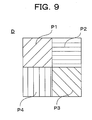
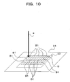
- the drawing process may comprise a first drawing process of drawing a first predetermined shape on the fusion layer by a first diffraction lattice produced by photographing interference fringes of a plurality of laser beams at a position of focused image formation of the interference fringes by the plurality of laser beams; and a second drawing process of drawing a second predetermined shape on the fusion layer by a second diffraction lattice produced by photographing interference fringes of a plurality of laser beams at a position shifted from the position of the first focused image formation of the interference fringes by the plurality of laser beams.
- the interference fringes with the second predetermined shape focus on a point different in the depth direction from the interference fringes with the first predetermined shape. Consequently, pseudo-three-dimensional impression can be expressed in the optical diffraction structure by the first and the second predetermined shapes.
- a method for copying an optical diffraction structure comprising: laminating an optical diffraction structure master-hologram having an object region to be copied having optical interference fringes in a concavo-convex form on a fusion layer formed on a base substrate, irradiating the optical diffraction structure master-hologram and the fusion layer which are laminated mutually with an energy beam in such a manner that an irradiation range is limited to a portion of the object region to be copied to fuse the fusion layer in the irradiation range by heat based on the energy beam, and transferring the interference fringes successively to the fusion layer by shifting the irradiation range in the object region to be copied, wherein the step of transferring comprises: a first transfer process of successively transferring the interference fringes to the fusion layer by shifting the irradiation range of the energy beam in a predetermined direction so as to draw scanning lines, and a second transfer process of
- the irradiation range of the energy beam is shifted in a predetermined direction so as to draw scanning lines, with the shifting, the temperature in the portion of the fusion layer in the irradiation range is increased by the heat based on the energy beam to fuse the portion of the fusion layer and thus the interference fringes overlaid on the fused portion are successively transferred to the fusion layer.
- the irradiation range is shifted along with the scanning lines while the energy beam is beamed to the boundary part of each scanning line drawn in the first transfer process.
- the fusion layer in the boundary part of the scanning line in the first transfer process is fused by the heat based on the energy beam, and, with the shift of the energy beam, the interference fringes in the boundary part of the scanning line are successively transferred to the fusion layer along the scanning line.
- both of the first transfer process and the second transfer process are only for successively transferring the concavo-convex form of an existing optical diffraction structure master-hologram, no development process is required. Also, since only an energy beam is beamed to fuse the fusion layer, no complicated and large scale apparatus or system is required.
- the fusion layer is easily fused in the centre part of the irradiation range of the energy beam and relatively difficult to fuse in the boundary part as compared with the centre part. Therefore, in the surface of the fusion layer on completion of the first transfer process, the portion of the centre part of the energy beam is mounted as compared with the portion of the boundary part and the surface of the fusion layer has a difference in height.
- the energy beam is beamed in such a manner that the boundary part of the scanning line of the energy beam in the first transfer process becomes the centre of the irradiation range, the portion that was difficult to be fused by the energy beam in the first transfer process can be fused. Accordingly, the difference in the height of the surface of the fusion layer caused by the first transfer process can be amended and, as a result, even in the case of carrying out copying by using the obtained optical diffraction structure as a master hologram, image deterioration by the copying can be prevented.
- optical diffraction structure means a structure including a hologram for forming a hologram image and a diffraction lattice, having optical interference fringes in form of the concavo-convex form, and generating a predetermined image based on the diffraction phenomenon of light.
- region to be copied means the range in the optical diffraction structure master-hologram where the interference fringes to be transferred in a one time transfer process are formed. Accordingly, the "region to be copied” may include entire interference fringes formed in the optical diffraction structure master-hologram and a plurality of "regions to be copied” may be included in the optical diffraction structure master-hologram.
- the embodiment of "drawing a scanning line in one direction” includes the case that respective lines are arranged in parallel if straight lines or wavy lines are employed as scanning lines transversely crossing the region to be copied and the case that scanning lines are drawn concentrically or spirally.
- energy beam means energy beams having heat themselves just like so-called heat beams and also energy beams having no heat themselves.
- heat of the energy beam means heat which the energy beam itself has and also heat which is generated by reaction at the irradiation point of the energy beam, e.g. activation of electron or chemical reaction.
- An embodiment of energy beam irradiation to the laminate of the fusion layer and the master hologram may include irradiation from the fusion layer side and irradiation from the master hologram side.
- the energy quantities of the energy beam in comparison of the first transfer process and the second transfer process may be the same in some cases and different in other cases, and may properly be set so as to obtain the flatness of the fusion layer of the finally obtained optical diffraction structure, depending on the material of the fusion layer and the type of the energy beam.
- An energy dose of the energy beam in the second transfer process may be equal to or lower than that of an energy beam in the first transfer process.
- the extent of the energy dose of the energy beam to be beamed is proportional to the size of the irradiation range and the size of the fused part of the fusion layer. Therefore, the energy quantities may be made different as described above, so that the fused part in the first transfer process can be made large and the fused part in the second transfer process can be made the same as or smaller than the fused part in the first process. In such a case, it is preferable that the energy dose of the energy beam in the second transfer process is in a range of 0.3 to 1 times that of the energy beam in the first transfer process.
- the method for forming a fine concavo-convex pattern employs a method for forming the fine concavo-convex patterns of the master hologram corresponding to relief patterns of a relief pattern sheet in a relief formation layer by irradiating the photothermal conversion layer with light to make the photothermal conversion layer generate heat in the state that the relief formation layer of the relief formation material and the relief patterns of the relief pattern sheet are brought into contact with each other, so that as compared with a conventional method involving heating by beaming radiant ray and simultaneously applying pressure for stamping with a stamp, the present method requires only that the relief formation layer and the relief patterns contact each other with no pressure application. Therefore, there is no need to use any apparatus such as a stamp or a pressure generating apparatus composed of complicated units, and the apparatus can be simplified and the cost of the apparatus can be low.
- the photothermal conversion layer is formed in the relief pattern sheet side, there is no need to form any photothermal conversion layer to be coloured dark by carbon black or the like in the relief formation material side and thus dark colouration of the relief formation material side can be avoided. Therefore, a product having fine concavo-convex patterns can be coloured with any optional colour and the method can be applied to produce a variety of products.
- the light irradiation can be carried out patternwise, so that the photothermal conversion layer can be made to generate heat patternwise and the relief patterns can be heated in optional patterns. Accordingly, simultaneously with the formation of the fine concavo-convex patterns, on-demand information can be produced.
- the relief formation layer of the relief formation material and the relief patterns of the relief pattern sheet are reliably brought into contact with each other and, therefore, the fine concavo-convex patterns can be formed more reliably.
- the diffraction lattice and the hologram can be expressed as one image only by beaming energy beam to a portion of the region to be copied in the master hologram and the diffraction lattice without costing high or taking troublesome work.
- a stable optical diffraction structure can be copied without high cost or troublesome work by beaming an energy beam to the optical diffraction structure master-hologram while drawing scanning lines in one direction and then beaming an energy beam in the boundary parts of each of the scanning lines.
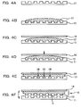
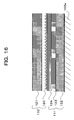
- a relief formation material 3 provided with a relief formation layer 2 of a thermoplastic ionising radiation-curable resin for forming fine concavo-convex patterns is formed on the surface of a substrate 1 composed of a polyethylene terephthalate film and so on.
- a relief pattern sheet 6 having relief patterns 5 corresponding to the fine concavo-convex patterns of the master hologram is laminated on a substrate 4 composed of a polyethylene terephthalate film and so on.
- a photothermal conversion layer 7 is formed between the substrate 1 of the relief formation material 3 and the relief formation layer 2.
- the photothermal conversion layer 7 is irradiated with light 8, such as laser beam(s), from the substrate 4 side of the relief pattern sheet 6.
- the photothermal conversion layer 7 generates heat in the portion where the light is beamed.
- the heat of the photothermal conversion layer 7 is transmitted to the portion of the relief formation layer 2 contacting the heated portion of the photothermal conversion layer 7 to heat and fuse the thermoplastic resin of the relief formation layer 2.
- the fine concavo-convex shape corresponding to the relief patterns 5 is formed in the relief formation layer 2.
- the relief patterns 5 are brought into contact with and closely attached to the relief formation layer 2 and there is no need to apply pressure between the relief formation material 3 and the relief pattern sheet 6.
- a laminate obtained by laminating the relief formation material 3 and the relief pattern sheet 6 may be sandwiched between supporting bodies of glass plates or the like to fix and hold the laminate.
- the adhesion of the relief formation layer 2 and the relief patterns 5 may be carried out by vacuum adsorption for sucking and evacuating air between them by a vacuum pump or the like.
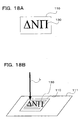
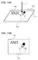
- the fine concavo-convex patterns 9 of the master hologram are formed on the surface of the relief formation layer 2 and a relief pattern formation body 10 having the fine concavo-convex patterns 9 fixed thereon is obtained.
- ionising radiation is beamed to the relief formation layer 2 having the fine concavo-convex patterns 9 thereon to cure the ionising radiation-curable resin of the relief formation layer 2.
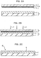
- Figs 2A to 2C show another example of a method for forming a fine concavo-convex pattern.
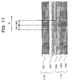
- the photothermal conversion layer 7 is formed in the relief formation material 3 side and light irradiation is carried out from the relief pattern sheet 6 side.
- the photothermal conversion layer 7 may be formed in the relief pattern sheet 6 side. More particularly, as shown in Fig. 2A, the photothermal conversion layer 7 is formed between the substrate 4 of the relief pattern sheet 6 and the relief patterns 5 and the relief formation material 3 is composed of the substrate 1 and the relief formation layer 2 without photothermal conversion layer.
- the relief pattern sheet 6 and the relief formation material 3 are closely attached to each other so as to bring the relief formation layer 2 and the relief patterns 5 into contact with each other.
- the photothermal conversion layer 7 is irradiated from the relief pattern sheet 6 side with light 8 to generate heat at the photothermal conversion layer 7.
- the thermoplastic resin of the relief formation layer 2 is thus fused or softened to form the fine concavo-convex shape corresponding to the relief patterns 5 in the relief formation layer 2.
- the fine concavo-convex patterns 9 of the master hologram are formed on the surface of the relief formation layer 2 to obtain the relief pattern formed body 10 in which the fine concavo-convex patterns 9 are fixed.
- ionising radiation is beamed to the relief formation layer 2 having the fine concavo-convex patterns 9 formed thereon to cure the ionising radiation-curable resin of the relief formation layer 2.
- the relief pattern formed body 10 since the finally obtained relief pattern formed body 10 has no photothermal conversion layer 7, the relief pattern formed body may be coloured with any optional colour and can give rise to excellent design.
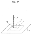
- an apparatus for generating laser beam may be employed. Further, in the case of beaming light to the photothermal conversion layer 7, light is beamed at spots from an irradiation source while the spots to which the light is beamed are moved so as to scan a predetermined region. The light irradiation is thereby carried out to a desired portion.
- beaming light in such a manner, only the required and optimum heat generation is provided for the required parts of the photothermal conversion layer 7 and, therefore, the effect of heat can be suppressed to the minimum.
- beaming light to the laminate body of the relief pattern sheet 6 and the relief formation material 3 as a support for the laminate body, an XY stage, a drum, or the like can be used.
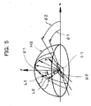
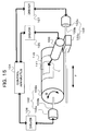
- Fig. 3 shows an explanatory drawing schematically showing one example of an apparatus that can be employed for the method for forming a fine concavo-convex pattern.
- the apparatus shown in Fig. 3 comprises a laser head 21 as a light irradiation source and an XY stage 22 for controlling the irradiation position.
- the laser head 21 is provided with a laser driver 25 as a control system capable of adjusting or turning on or off the output energy of the light source and is constructed to be controlled by a PC 24.
- the laser head 21 is also provided with an optical system, such as mirrors and lenses, for adjusting the laser light source and the optical path and the focal point of the emitted light.
- the XY stage 22 is formed so as to set a laminate body 23, which is obtained by closely attaching the relief formation material 3 and the relief pattern sheet 6 to each other, on the surface.
- An XY stage controller 26 for controlling the movement of the XY stage 22 is connected so as to control the movement by the PC 24.
- the laminate body 23 which is obtained by closely attaching the relief formed body 3 and the relief pattern sheet 6 to each other, is set on a predetermined position of the surface of the XY stage 22.
- the laser head 21 is positioned at a starting point.
- the XY stage 22 is then moved and the laser beam irradiation by the laser head 21 is turned on or off to carry out light irradiation in the predetermined pattern.
- the light 8 beamed from the laser head 21 is made to be in spot shape with a diameter of not over 100 ⁇ m and is used for scanning the laminate body 23 in a predetermined scanning pattern in the XY direction by operation of the XY stage 22 so as to irradiate the entire body of the laminate body 23 with the light 8.
- the photothermal conversion layer 7 of the laminate body 23 is irradiated with the laser beam as a small spot and the spot of the laser beam is successively moved by the scanning, so that the duration of the laser beam irradiation on any particular region is extremely short. As a result, only a very narrow region, like the spot in the relief formation layer 2 or the relief patterns 5 contacting the photothermal conversion layer 7, is heated for a short time. After, when the resin of the relief formation layer 2 is fused to form the pattern, the resin is quickly cooled and the pattern formation state is immediately fixed.
- the wavelength of the light with a high transmittance to the substrate 1 and the substrate 4 so as to cause no damage to these substrates with the light transmitted through the substrates.
- a laser beam and a polyethylene terephthalate film sometimes referred to as PET
- PET polyethylene terephthalate film
- on-demand information can be produced by beaming light patternwise, not entirely, along with any optional pattern, and generating heat in the photothermal conversion layer 7 patternwise to heat the relief formation layer 2 or the relief patterns 5 in the optional shape.
- on-demand information for example, particular information such as ID numbers of individuals can be used.
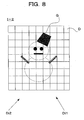
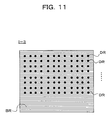
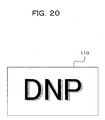
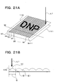
- the particular concavo-convex patterns in which general information or common information such as a company's name is recorded are formed in the entire body of the relief formation layer 2 and on the portions of the gaps other than the regions where the concavo-convex patterns are formed or on the above-mentioned concavo-convex patterns, letters and signs of the particular information are directly drawn and recorded in form of concavo-convex patterns by scanning with the laser beam.
- the concavo-convex patterns of the common information are formed and at the same time, on-demand information can be recorded.
- the concavo-convex pattern formed body in which the particular information is recorded in the above-mentioned manner can improve the security if it is used as a security card such as an ID card.
- the material placed between the photothermal conversion layer 7 and the light source may be any material which can practically transmit light so as to transmit light to the photothermal conversion layer 7.
- UV rays UV-A, UV-B, and UV-C
- visible light rays ⁇ -beam
- X-rays X-rays
- electron beam electron beam
- UV rays and electron beam are preferable.
- a UV lamp such as an ultra high pressure mercury lamp, a high pressure mercury lamp, a low pressure mercury lamp, a carbon arc, a black light, a metal halide lamp or the like may be used as the light source.
- the wavelength of the UV rays is generally about 200 to 400 nm and the wavelength may be selected depending on the composition of the resin layer.
- the irradiation dose is also controlled depending on the composition of the resin layer, the output power of the UV lamp, and the processing speed.
- the apparatuses to be employed are those which comprise various kinds of electron beam accelerators such as Cockcroft-Walton type, Van de Graaff type, the resonance transformer type, the insulator core transformer type, the linear type, the dynamitron type, and the high frequency type, and which can beam electron beams in an electron curtain manner or a beam scanning manner or the like.
- electron beam accelerators such as Cockcroft-Walton type, Van de Graaff type, the resonance transformer type, the insulator core transformer type, the linear type, the dynamitron type, and the high frequency type
- Electro-curtain (trade name) which can beam electron beams evenly in a curtain manner from a linear filament can be exemplified.
- the irradiation dose of the electron beam is controlled by beaming about 0.5 to 20 Mrad of electron beam with electrons having an energy of generally 100 to 1,000 keV, preferably 100 to 300 keV.
- the oxygen concentration is controlled to be not over 500 ppm, preferably about 200 ppm in general.
- any film type (including sheet type) material may be used without any particular limitation.
- Practical examples of usable films are polymer films (plastics films) such as films of polyester resins, e.g. polyethylene terephthalate, polybutylene terephthalate, polyethylene naphthalate, polyethylene terephthalate-isophthalate copolymer, terephthalic acid-cyclohexanedimethanol-ethylene glycol copolymer, and extruded film of polyethylene terephthalate/polyethylene naphthalate mixture; polyamide type resins, e.g. nylon 6, nylon 6,6, and nylon 610; polyolefin type resins, e.g.
- polyethylene, polypropylene, and polymethylpentene vinyl type resins, e.g. poly vinyl chloride; acrylic type resins, e.g. polyacrylate, polymethacrylate, and polymethylmethacrylate; imide type resins; engineering plastics, e.g. polyarylate, polysulfone, polyether sulfone, polyphenylene ether, polyphenylene sulfide (PPS), polyaramide, polyether ketone, polyether nitrile, polyether ether ketone, and polyether sulfide; styrene type resin, e.g. polycarbonate and ABS resin; and cellulose type films, e.g.
- plastics films may be stretched films or non-stretched films and in terms of the strength improvement, uniaxially or diaxially stretched films are preferable.
- the substrate 1 other than the plastics films, paper, synthetic paper, and metal films such as iron and aluminium can be used. In terms of the light transmission property, plastics films are preferable.
- the above-mentioned films may be used alone or laminates of two or more kinds of the above-mentioned films may be used.
- the thickness of the substrate 1 is generally about 5 to 2000 ⁇ m.
- a film of a polyester, such as polyethylene terephthalate or polyethylene naphthalate is used preferably since it has heat resistance, size stability, and ionising radiation resistance and a film of polyethylene terephthalate is used more preferably.
- the face of substrate 1 to be coated may be subjected to treatment for easy adhesion such as corona discharge treatment, plasma treatment, ozone treatment, flame treatment, primer (sometimes called anchor coating, adhesion promoter, or easy adhesive) treatment, preheating treatment, dust removal treatment, or alkaline treatment.
- the substrate 1 may contain additives such as a filler, a plasticizer, a colouring agent, or an antistatic agent.
- thermoplasticity to be used for the relief formation layer 2 ionising radiation-curable resins in solid state at a normal temperature and having heat formability are preferably used.
- ionising radiation-curable resins contain thermoplastic substances having radical polymerizable unsaturated groups. Practically there are following two types of resins.
- radical polymerizable unsaturated monomers are for improving the crosslinking density and heat resistance at the time of ionising radiation and examples to be used as the monomers other than the above exemplified compounds are ethylene glycol diacrylate, ethylene glycol dimethacrylate, polyethylene glycol diacrylate, polyethylene glycol dimethacrylate, hexanediol diacrylate, hexanediol dimethacrylate, trimethylolpropane triacrylate, trimethylolpropane trimethacrylate, trimethylolpropane diacrylate, trimethylolpropane dimethacrylate, pentaerythritol tetraacrylate, pentaerythritol tetramethacrylate, pentaerythritol triacrylate,
- the above-mentioned ionising radiation-curable resin is sufficiently cured by electron beam.
- a photopolymerization initiator such as acetophenones, benzophenones, Michlers's benzoyl benzoate, ⁇ -aminoxime ester, tetramethylmeuram monosulfide, and thioxanthones and base on the necessity, a photosensitizer such as n-butylamine, triethylamine, and tri-n-butylphosphine.
- the above-mentioned ionising radiation-curable resin can be cured by heat energy if a proper catalyst exists.
- the ionising radiation-curable resin being in solid state at a normal temperature and having heat formability to be used for the relief formation layer 2 is applied to the substrate 1 in a thickness of generally 0.1 to 50 ⁇ m, preferably 0.5 to 5 ⁇ m, in the case a hologram is copied in form of concavo-convex patterns.
- the thickness differs depending on the intended use of the fine concavo-convex patterns to be copied.
- the relief formation layer 2 can be formed on the substrate 1 by known coating methods such as spin coating, knife coating, roll coating, or bar coating. In the case of forming the relief formation layer 2 on a portion of the substrate 1, a common printing technique such as screen printing and gravure printing, or a transfer method, can be employed.
- the relief formation material 3 comprising the relief formation layer 2 of the ionising radiation-curable resin in solid state at a normal temperature formed on the substrate 1
- the relief formation layer 2 is formed in solid state at a normal temperature to form in a finger-touch-dry state, the material 3 can be stored while being laminated.
- a separation layer (not illustrated) may be formed between the substrate 1 and the relief formation layer 2.
- the separation layer can provide separation property, wear resistance, and printing suitability between the substrate 1 and the relief formation layer 2.
- the resin of the separation layer a wide range of conventionally known resins such as acrylic resins, cellulose type resins, vinyl resins, polyester resins, urethane resins, olefin resins, amide resins, and epoxy resin may be used.
- the thickness of the separation layer is generally 0.05 to 10 ⁇ m, preferably 0.2 to 2 ⁇ m.
- the relief patterns 5 of the relief pattern sheet 6 are formed as concavo-convex patterns corresponding to the fine concavo-convex patterns 9 of the master hologram.
- holograms such as relief holograms, optical diffraction structure such as diffraction lattice, and hair lines may be used.
- the images of the hologram photographed images of actual objects, signs, letters, numerals, and illustrations may be used.
- the hologram images themselves can be obtained by calculation of hologram diffraction lattices, or can be produced with a proper means such as a holographic stereogram from digital images taken by a digital camera or from two- or three-dimensional images data of digital images of computer graphics other than photography of an actual object.
- the diffraction lattices can express images of letters or the like by their outlines.
- a hologram where light intensity distributions of interference fringes caused by light interference between object light is recorded in the form of ragged patterns and reference light and diffraction lattices can be employed.
- laser regeneration hologram such as Fresnel hologram, Fraunhofer hologram, lens-less Fourier transform hologram, and image hologram
- incandescence regeneration hologram such as rainbow hologram
- holograms based on their principles: colour hologram; computer hologram; hologram display; multiplex hologram; holographic stereogram; and holographic diffraction lattice.
- the diffraction lattice there are holographic diffraction lattices using hologram recording means; and further any optional diffraction lattice based on calculation by mechanically or graphically producing a diffraction lattice with a precision lathe or an electron beam drawing apparatus.
- hologram and diffraction lattices may be recorded singly or multiple-recorded or recorded in combination.
- the diffraction lattice can give particular brightness with excellent design properties by assembling a plurality of regions different in the ridge direction and/or ridge interval and/or shape of the concavo-convex form and/or height of the concavo-convex form, that is, regularly or randomly combining a plurality of regions having different diffraction directions.
- a variety of known methods may be employed as a method for forming relief patterns 5 on the surface of the substrate 4 from the fine concavo-convex patterns of a master hologram.
- a method for forming the relief patterns 5 there are methods: (1) a hologram copying method (known as a semi-dry copying method) described in Japanese patent application laid-open no.
- 6-85103 by forming fine concavo-convex patterns of a master hologram for copying on an ionising radiation-curing resin by pressure application, beaming ionising radiation after or simultaneously with the pressure application, and separating the resin and the master hologram; and (2) a photo polymerization method (known as a 2 P method) by applying an ionising radiation-curable resin in liquid state to the surface of the master hologram for copying, curing the resin by beaming ionising radiation after spreading the resin on the surface to form fine ragged patterns, and obtaining a stamper by separating the formed resin from the master hologram for copying.
- a photo polymerization method known as a 2 P method
- Figs. 4A to Fig.4F show the flow diagrams of the relief pattern formation method from a master hologram by 2 P method.
- a master hologram 11 having an uneven relief is used and as shown in Fig. 4B, an ionising radiation-curable resin composition 12 is dropwise titrated on the master hologram 11.
- the substrate 14 is set on the resin and pressurised to spread the ionising radiation-curable resin composition 12 to evenly fill the recessed parts.
- Fig. 4A a master hologram 11 having an uneven relief is used and as shown in Fig. 4B, an ionising radiation-curable resin composition 12 is dropwise titrated on the master hologram 11.
- the substrate 14 is set on the resin and pressurised to spread the ionising radiation-curable resin composition 12 to evenly fill the recessed parts.
- ionising radiation such as UV rays is beamed from the master hologram 11 side or the substrate 14 side to cure the ionising radiation-curable resin composition 12.
- Fig. 4F the ionising radiation-curable resin composition 13 and the substrate 14 united together by curing are separated form the master hologram 11 to obtain a relief pattern sheet 6 comprising the ionising radiation-curable resin composition 13 on the substrate 14 (the substrate 4) having the relief patterns 5.
- plastics films As the material of the substrate 4 of the relief pattern sheet 6, metals, glass, or plastics films may be used.
- a plastics film is used preferably.
- a plastics film exemplified for the substrate 1 of the relief formation material 3 may be used.
- the photothermal conversion layer 7 may be formed on the relief formation material 3 side, the relief pattern sheet 6 side, or both sides.
- the photothermal conversion layer 7 may be any suitable material provided it can absorb light 8 and convert the light to heat to generate heat, and may be a layer formed using a binder resin such as thermoplastic resin and a heat-curable resin in which a light absorbing colouring material such as carbon black is dissolved or dispersed.
- the thickness of the photothermal conversion layer 7 is generally 0.1 to 5 ⁇ m and preferably 0.3 to 3 ⁇ m.
- the light absorbing colouring material to be used for the photothermal conversion layer 7 a variety of compounds can be used depending on the light to be beamed.
- a colouring material suitable for a semiconductor laser there are colouring materials such as polymethine type such as cyanine type and pyrylium type; phthalocyanine type colouring materials such as copper phthalocyanine; naphthalocyanine type colouring materials; dithiol metal complex type colouring materials; naphthoquinone type colouring materials; anthraquinone type colouring materials; tirphenylmethane type colouring materials; aluminium type colouring materials; and diimmonium type colouring materials.
- the photothermal conversion layer 7 can be formed by known coating means.
- polyesters As the binder resin to be used for the photothermal conversion layer 7, polyesters; acrylic, epoxy, butyral and acetal resins; vinyl chloride-vinyl acetate copolymer; polyurethanes; thermoplastic high molecular weight epoxy, can be exemplified. Polyesters are preferable.
- the relief pattern formed body 10 obtained by a method for forming a fine concavo-convex pattern may be used as a master hologram for copying as it is. It may be used in a label form by layering an adhesive or separation paper on the substrate 1 side or a transfer material for hot stamp or a material for heat transfer using a thermal head by making it as a transfer foil by forming an adhesive layer on the substrate side.
- the photothermal conversion layer 7 can be provided either in the relief pattern sheet 6 or in the relief formation material 3 to be used in the formation method described below.
- a plurality of relief pattern sheets 6 having diffraction lattice patterns as relief patterns 5 are made ready in such a manner that the orientation angles of the diffraction lattice patterns are made different from one another and the respective diffraction lattice patterns are formed on relief formation layers 2 in such a manner that the transferred diffraction lattice patterns are adjoined with each other in a predetermined direction on the relief formation material 3.
- the diffraction lattice patterns are rotated, image patterns composed of bright points of the diffraction light rays are observed as if they are moving and so-called moving images are formed.
- the moving state may be continuous, semi-continuous, or discontinuous in a predetermined direction.
- the alteration of the orientation angles of the adjoining diffraction lattices should be within 5 degrees. If the angles are changed more than that, the bright points move semi-continuously or discontinuously.
- Orientation angles means the angles of plane directions of the lines composing the diffraction lattices.
- the bright points of the respective diffraction lattice areas K1...Kn are determined by the orientation angles and the diffraction angles of diffraction lattices.
- a diffraction lattice area K1 has an orientation angle ⁇ 1 and a diffraction angle ⁇ 1 and an adjoining diffraction lattice area K2 has an orientation angle ⁇ 2 and a diffraction angle ⁇ 2 when light comes in at a predetermined angle.
- a plurality of kinds of diffraction lattice patterns 5 having the respective diffraction lattice areas K1...Kn whose bright points have orientation angles and diffraction angles so as to draw a desired shape on the hemisphere HS may be selected.
- the diffraction angles are determined based on the diffraction lattice pitches and alteration of the bright points can be obtained in the perpendicular direction by changing the diffraction angles.
- the first image body I-1 is composed as a diffraction lattice row R of a plurality of diffraction lattice areas K1...Kn with different orientation angles, which adjoin each other in the predetermined direction H.
- a method for forming the diffraction lattice row R will be described practically with reference to Fig. 7.
- a relief pattern sheet 6 having the diffraction lattice pattern 5 corresponding to the diffraction lattice area K1 and a relief formation material 3 are closely attached to obtain a laminate 23 in the above-mentioned manner.
- the laminate 23 is disposed on a predetermined position of an XY stage 22.
- the photothermal conversion layer 7 is irradiated with light 8 so as to form the diffraction lattice pattern 5 on the region A of the relief formation layer 2 where the diffraction lattice area K1 is to be formed.
- the diffraction lattice pattern 5 is formed only in the area A.
- the diffraction lattice area K1 is formed in the area A where the area K1 is to be formed.
- the scanning lines SC1 are made visible for making the explanation easily understandable, and therefore, they are not actually observed with the naked eye.
- the irradiation starting position and the irradiation pattern of the light 8 may be controlled by PC 24.
- the corresponding diffraction lattice patterns 5 may be formed in regions where the diffraction lattice patterns 5 are to be formed so as to make the areas K2...Kn adjoining in the predetermined direction H.
- the irradiation starting positions and the irradiation patterns of the light rays 8 in relation to the respective diffraction lattice areas K1...Kn to be formed may be controlled by the PC 24.
- the diffraction lattice row R is formed on the relief formation layer 2.
- the obtained relief formation material 3 may be further processed properly to obtain the first image body I-1 of a moving image.
- the control of light irradiation such as the irradiation pitches, irradiation intensity, and moving speed corresponding to the formation of the respective diffraction lattice areas K1...Kn may be carried out by previously setting the respective values for the control and performed by the PC 24.
- the formation order of the respective diffraction lattice areas K1...Kn is optional.
- the sizes of the respective diffraction lattice areas K1...Kn are same. However, they may be different in area.
- the predetermined direction H is not necessarily straight, and can be bent at predetermined angles, spiral, or curved.
- the diffraction lattice row R formed in the first image I-1 is not necessarily single, and a plurality of rows may be formed.
- a plurality of relief pattern sheets 6 are made ready while each of the relief patterns 5 are made different from one another and a plurality of the relief patterns 5 are combined so as to compose one generatrix assembly, and the respective generatrices of a plurality of relief patterns 5 may be formed on the relief formation layer 2 so as to observe images corresponding to respective characteristics of each of the plurality of relief patterns 5 by combining a plurality of the generatrix assemblies.
- an image body containing images corresponding to respective characteristics of a plurality of the relief patterns 5 can be obtained in a single plane.
- the characteristics of the relief patterns 5 may include images obtained owing to the light interference and the directions in which the images are observed.
- One generatrix assembly is preferably small enough not to be seen with the naked eye and using light, fine interference fringes can be formed. Therefore, the method is applicable in the case that the kinds of relief patterns 5 contained in the generatrix assembly of a predetermined size increase.
- a relief pattern sheet 6 having hologram patterns as the relief patterns 5 will be used.
- the relief patterns 5 in this formation method are called hologram patterns 5.
- a second image body I-2 in which four type images are observed from four observation directions will be described.
- the second image body I-2 is divided into divided divisions D as a plurality of generatrix assemblies, as shown in Fig. 9, the respective divided divisions D are composed of four generatrix portions P1 to P4.
- the generatrix portions P1 to P4 they are called simply generatrix portions P.
- the boundaries of the respective divided divisions D of Fig. 8 and the boundaries of the respective generatrix portions P of Fig. 9 are made visible only for making the explanation easily understandable and are not practically observable lines. Further, it is preferable that the divided divisions D are small enough not to be observed.
- Different kinds of hologram patterns 5 are formed in the respective generatrix portions P1 to P4 and each of the generatrix portions P1 to P4 functions as a generatrix, so that images corresponding to the characteristics of the respective hologram patterns 5 can be observed in the respective observation directions.
- Di1 corresponding to the generatrix portion P1 an image G shown in Fig. 8 can be observed
- Di2 corresponding to the generatrix portion P2 another image can be observed.
- an image different from those of other generatrix portions can be observed in a different observation direction from those of other generatrix portions.
- first hologram patterns 5 to express the respectively different images and to have respectively different observation directions are selected and each of the hologram patterns 5 corresponds with each of the generatrix portions P1 to P4 in 1 to 1 relation.
- a method for forming hologram patterns 5 expressing the image G in the observation direction Di1 in the generatrix portion P1 will be described.
- a relief pattern sheet 6 having the hologram patterns 5 and a relief formation material 3 are closely attached in the above-mentioned manner to obtain a laminate 23.
- the laminate 23 is set at a predetermined position of the XY stage 22.
- the photothermal conversion layer 7 is irradiated with light 8 so as to form the hologram patterns 5 only in the areas B1...B1 of the relief formation layer 2 where the generatrix portion P1 is to be formed.
- the areas B1...B1 (slanting line part) where the generatrix portion P1 is to be formed are obtained by dividing the pattern formation region PR into divided divisions D and defining the areas corresponding to the generatrix portion P1 in the respective divided divisions D as the areas B1.
- the pattern formation region PR is the region corresponding to the second image body I-2.
- the generatrix portion P1 functioning as a generatrix of the hologram patterns 5 is formed in the areas B1.
- the irradiation position and the irradiation pattern of the light 8 may be previously programmed and controlled by the PC 24.
- the respective areas B1 are shown to be big enough to be observed for explanation easiness but they are actually so small as not to be observed with the naked eye.
- pattern formation should be carried out in the regions where the generatrix portions P of the hologram patterns 5 are to be formed by using relief pattern sheets 6 of the hologram patterns 5 corresponding to the respective generatrix portions P2 to P4.
- the irradiation position and the irradiation patterns of light 8 in relation to each of the regions, where the corresponding generatrix portion P is to be formed, may be controlled by the PC 24.
- the respective hologram patterns 5 are formed in all of the generatrix portions P. If necessary, the obtained relief formation material 3 may be processed further to obtain the second image body I-2.
- the second image body I-2 in which four type holograms are expressed by dividing the region into four divided divisions D is formed.
- the number of the generatrix portions to be included in one divided division D is not particularly limited if it is two or higher.
- the plural kinds of the hologram patterns 5 which are equal to the number of the divided generatrix portions are used for the formation.
- the respective hologram patterns 5 are formed in the entire body of the respective generatrix portions.
- the hologram patterns 5 are formed only partially in the generatrix portions P in some cases.
- respective diffraction lattice patterns 5 each corresponding to three primary colours are made to correspond to the respective generatrix portions P, so that a colour hologram in a specific observation direction can be expressed.
- the relief pattern sheet 6 having the relief patterns 5 a first relief pattern sheet having first relief patterns and a second relief pattern sheet 6 having second relief patterns different from the first relief patterns are made ready, and the first and the second relief patterns may be formed in the relief formation layer 2 in such a manner that fine regions where the second relief patterns are formed have shapes so small as not to be observed with the naked eye and assembled in the background region which is formed by using the first relief patterns.
- the obtained image body in which the background region formed by using the first diffraction lattice patterns is observed with the naked eye but the shape of each fine region which is formed by using the second relief patterns is not recognised with the naked eye, and the shape is recognised as a point or a line.
- the fine regions are observed like point or linear patterns on the first diffraction lattice patterns with the naked eye and their shapes are recognised only when they are magnified with a microscope or the like. If the shapes are made to be letters or marks, the obtained image body can be used for security means.
- a relief pattern sheet 6 having diffraction lattice patterns as the relief patterns 5 is used.
- the relief patterns 5 are called diffraction lattice patterns 5.
- the third image body I-3 is composed of the background region BR in which first diffraction lattice patterns are formed and a plurality of fine regions DR...DR appearing as points assembled in the background region BR when observed with the naked eye.
- the respective fine regions DR looking only like points with the naked eye are formed to be in a star shape by the second diffraction lattice patterns different from the first diffraction lattice patterns as shown in Fig. 12.
- the shapes of the fine regions DR are recognised only when they are magnified with a microscope or the like.
- the formation method for the third image body I-3 will be described more particularly with reference to Fig. 13 and Fig. 14.
- the first relief pattern sheet 6 having the first diffraction lattice patterns 5 to be formed in the background region BR and a relief formation material 3 are closely attached in the above-mentioned manner to obtain a laminate 23.
- the laminate 23 is set at a predetermined position of a stage XY stage 22.
- the photothermal conversion layer 7 is irradiated with light 8 in such a manner that the first diffraction lattice patterns 5 are formed in the region C1 of the relief formation layer 2 where the background region BR is to be formed.
- the first diffraction lattice patterns 5 are formed in the region C1 and, accordingly, the background region BR is formed in the region C1.
- the background region BR may be formed in such matter that formation of the first diffraction lattice patterns 5 is avoided in the region where formation of the second diffraction lattice patterns 5 is carried out.
- the irradiation position and the irradiation patterns of the light 8 are controlled by the PC 24.
- the scanning lines SC3 of the light are shown only for explanation and they are not actually observed with the naked eye.
- the first relief pattern sheet 6 is separated from the relief formation material 3 and, as shown in Fig. 14, the second relief pattern sheet 6 having the second diffraction lattice patterns 5 and the relief formation material 3 are closely attached to each other in the above-mentioned manner to obtain a laminate 23.
- the laminate 23 is put at a predetermined position of the XY stage 22.
- the photothermal conversion layer 7 is irradiated with light 8 in such a manner that the second diffraction lattice patterns 5 are formed in the regions C2...C2 where the fine regions BR of the relief formation layer 2 are to be formed.
- the second diffraction lattice patterns 5 are formed in the region C2.
- fine regions DR are formed in the region where they are to be formed.
- the irradiation position and the irradiation pattern of the light 8 may be controlled by the PC 24.
- Each region C2 is shown with a size observed with the naked eye for explanation convenience, but it does not have a size large enough to be recognised. Further, the boundary lines of each region C2 are also shown for explanation convenience, but they are not observable with eye.
- the background region BR and fine regions DR are formed in the relief formation layer 2.
- the third image body I-3 can be obtained by processing properly the obtained relief formation material 3.
- the shapes formed by the second diffraction lattice patterns have a star form, but the shape is not limited to a star, and can be letters or designed patterns.
- the respective relief patterns to be used for the background region BR and the fine regions DR should be different and are not limited to the diffraction lattice patterns.
- the laminate 23 is set on the XY stage at the time of formation of the first to the third image bodies I-1 to I-3, but it may be attached to a side face of a drum by vacuum adsorption. In such a case, the perpendicular direction is controlled by rotation of the drum and the horizontal direction may be controlled by moving the laser head 21 of the light 8 in the horizontal direction.
- the photothermal conversion layer 7 is formed independently, if a substance increasing the photothermal conversion efficiency is added to any layer of either the relief formation material 3 or the relief pattern sheet 6, it is not necessarily required to form the photothermal conversion layer 7.
- relief pattern sheets 6 having the first image body I-1, the second image body I-2, or the third image body I-3 obtained in the above-mentioned formation method as a master hologram are used and irradiation of the light 8 is controlled so as to form all of the concavo-convex patterns of the respective image bodies, the respective image bodies can easily be copied.
- FIG. 15 shows an optical diffraction structure production apparatus to be used in the embodiment.
- a laser irradiation apparatus 100 for irradiating with an IR laser L as energy beam a drum apparatus 102 for holding a master hologram, and a transportation apparatus 103 are connected to a control apparatus 104 for controlling the operation of the above-mentioned apparatuses through drivers 105, 106, and 107 respectively.
- the drum apparatus 102 is provided with a column type drum 102a and a motor 102c for rotating the drum 102a on the axis 102b in the direction Q.
- Small holes are formed in the entire outer circumferential face of the drum 102a and the air in the inside of the drum 102a is sucked by a suction pump (not shown), so that negative pressure is generated in the inside of the drum 102a to attach a master hologram 110 and a film 111 for hologram formation to the surface of the drum 102a.
- the respective structures of the master hologram 110 and the film 111 for hologram formation will be described later.
- the transportation apparatus 103 is provided with a transportation part 103 and a motor 103c for moving the transportation part 103a in the direction parallel to the axial direction of the drum 102a, that is in the direction shown by the arrow F, on a rail 103b. Since the laser irradiation apparatus 100 is set on the transportation part 103a, along with the transportation of the transportation part 103a, the laser irradiation apparatus 100 can move in parallel to the side face of the drum 102a.
- the laser irradiation apparatus 100 irradiates the master hologram 110 attached to the side face of the drum 102a with IR laser L.
- the irradiation range of the IR laser L in the master hologram 110 can be shifted by the parallel movement of the laser irradiation apparatus 100 by the above-mentioned transportation apparatus 103 and rotation of the drum 102a.
- the control apparatus 104 comprises a computer comprising a CPU and various peripheral circuits such as RAM and ROM necessary for the operation of the CPU and is employed to control the operations of the above-mentioned laser irradiation apparatus 100, drum apparatus 102, and transportation apparatus 103 according to previously installed programs. Accordingly, shift of the irradiation range of the IR laser L with which the master hologram 110 is irradiated by the laser irradiation apparatus 100 is controlled by the control apparatus 104.
- Fig. 16 shows the state that master hologram 110 and the film 111 for forming hologram to be used in this embodiment are laminated on the outer circumference of the drum 102a.
- the master hologram 110 is provided with a hologram layer 120 in which the interference fringes are formed in concavo-convex form and a base substrate layer 121 of polyethylene terephthalate.
- the master hologram 110 can be produced by a conventionally known method.
- the hologram to be used for the hologram layer 120 may be those which can record hologram information by the concavo-convex form in the material surface and are applicable for a conventional method for copying hologram by using a thermoplastic resin.
- holograms based on the Fresnel hologram, Fourier transform hologram, Fraunhofer hologram; and holograms utilising their principles, such as image hologram, holographic stereogram, and holographic diffraction lattice can be used.
- a diffraction lattice having the concavo-convex patterns evenly formed therein may be used and, in this case, the lattice patterns of the diffraction lattice are transferred to the film 111 for forming hologram.
- the film 111 for forming the hologram is composed by layering a primer layer 123 and a fusion layer 124 on the base substrate layer 122 of polyethylene terephthalate.
- the fusion layer 124 comprises wax, a thermoplastic resin, and a high heat conversion material as a substance for increasing the conversion efficiency from light energy of IR laser to heat energy.
- the thermoplastic resin and wax composing the fusion layer 124 may be those which are solid state at a normal temperature.
- the primer layer 123 functions as a primer for sticking the base substrate layer 122 and the fusion layer 124 to each other.
- Fig. 17 the master hologram 110 and the film 111 for forming hologram are attached to the outer circumference of the drum 102a as described above.
- the master hologram 110 and the film 111 for forming the hologram are layered to each other and irradiated from the base substrate layer 121 side with the IR laser L moving in the direction shown by the arrow C.
- an irradiation range W1 of the fusion layer 124 is heated by the heat of the IR laser L.
- the temperature of the irradiation range W1 of the fusion layer 124 reaches the fusing point, the fusion layer 124 in the range is fused and the interference fringes of the hologram layer 120 in the irradiation range W1 are transferred to the fusion layer 124.
- the IR laser L is shifted to an irradiation range W2.
- Fig. 17 shows the state that the interference fringes in the irradiation range W1 are transferred to the fusion layer 124 and the IR laser is shifted to the irradiation range W2.
- the temperature in the transferred range W1 of the fusion layer 124 decreases without a particular cooling process and the fused fusion layer 124 becomes cured.
- the fusion layer 124 in the range is fused and the interference fringes of the hologram layer 120 in the irradiation range W2 are transferred to the fusion layer 124.
- the interference fringes in the ranges which are irradiated with the IR laser L are successively transferred to the fusion layer 124.
- Fig. 19B shows an optical diffraction structure in which the interference fringes for producing a hologram image 130 are combined with a drawn image 133 with a predetermined form drawn by a diffraction lattice.
- the method for producing an optical diffraction structure comprises a hologram copying process and a diffraction lattice drawing process. The order of these two processes is optional. In this embodiment, the copying process is carried out first and the drawing process later.
- Fig. 18A shows a master hologram 110 in which the interference fringes for producing the hologram image 130 to be copied on the film 111 for forming the hologram are provided.
- the object range to be copied in this embodiment is the entire interference fringes formed in the master hologram 110.
- the film 111 for forming the hologram is stuck to the outer circumferential face of the drum 102a of the optical diffraction structure production apparatus (Fig. 15) and the master hologram 110 is layered thereon.
- the film 111 for forming the hologram and the master hologram 110 layered on the drum 102a are attracted to the outer circumference of the drum 102a.
- the master hologram 110 is smaller than the film 111 for forming the hologram.
- the film 111 for forming the hologram has a size such that the object range to be copied of the master hologram 11 can be transferred to the film 11 for forming the hologram.
- the master hologram 110 is irradiated with IR laser L.
- the irradiation position of the IR laser L is controlled by the program taken in the control apparatus 104. That is, the operation is executed by controlling the operations of drum apparatus 102 and the transportation apparatus 103. With the shift of the irradiation position, the interference fringes for producing the hologram image 130 are transferred to the fusion layer 124 of the film 111 for forming the hologram.
- the master hologram 110 in which the hologram image 130 is previously formed is easily transferred by IR laser L, even if the hologram image 130 is complicated, the hologram image can be copied easily by IR laser L within a short time.
- a diffraction lattice 132 is layered on the film 111 for forming the hologram to which the hologram image 130 has been transferred.
- the diffraction lattice 132 has constant concavo-convex patterns formed evenly.
- the diffraction lattice 132 having the layered structure similarly to the master hologram 110 and having constant concavo-convex patterns formed evenly in the layer corresponding to the hologram layer 120 is used.
- Fig. 19A shows the state that the drawing image 133 is drawn by the IR laser L.
- the concavo-convex patterns of the diffraction lattice to be transferred in the drawing process are not a hologram according to a strict definition. However, the film 111 for forming hologram to be used in the copying process is used as it is.
- the optical diffraction structure in which the hologram image 130 and the drawing image 133 are combined on the film 111 for forming the hologram can be produced. Accordingly, it is made easy to produce for example a hologram synthesised employee badge comprising the hologram image 130 as a company mark and the drawing image 133 as the face of the employee, or to produce a hologram synthesised photograph having a cubic background if the hologram image 130 is the cubic background and the drawing image 133 is a face of a person.
- the following description is a method for producing an optical diffraction structure having deep depth feeling by making another diffraction lattice 132 ready which has a focused image of the interference fringes at a position different from the focused image position of the interference fringes of the diffraction lattice 132 in the depth direction, and transferring the interference fringes of the other diffraction lattice 132 to the fusion layer 124.
- a dry plate which is an object to be photographed, is set at a position where the interference fringes are focused to form an image (hereinafter, referred to as a focusing position).
- the other diffraction lattice 132 can be obtained by photographing the dry plate at a position shifted in the horizontal direction from the focusing position (e.g. a position shifted from the focusing position by -4 mm, -2 mm, +2 mm or +4 mm in the horizontal direction).
- the other diffraction lattice 132 is produced by setting the dry plate at the position shifted from the focusing position by -4 mm and, by the procedure that is the same as that for drawing the drawing image 133 as the first predetermined shape by the diffraction lattice 132 in the above-mentioned drawing process, the second predetermined shape to be the background of the drawing image 133 is drawn on the film 111 for forming the hologram by the other diffraction lattice 132.
- the hologram image 130 is made as a company mark and the drawing image 133 drawn by the diffraction lattice 132 produced by the above-mentioned normal production method is made as a face of an employee, an apparent distance can be generated between the face of the employee and the background and thus a cubic image expression can be formed in the produced optical diffraction structure.
- the hologram copying method and the method for producing an optical diffraction structure are not limited to the above-mentioned embodiment and may be carried out in variously modified states.
- IR laser L is used as the energy beam, but electron beam and X-ray may be used.
- a film 111 for forming the hologram having a fusion layer 124 generating heat by using the energy beam may be used properly.
- the speed of shifting of the irradiation range of the IR laser L, electron beam or the like may properly be set to a proper speed at which the hologram and the diffraction lattice can be transferred without any particular cooling process, on the basis of the composing materials of the master hologram 110 and the film 111 for forming the hologram and the irradiation range.
- any material with which the method is performed can be used for the base substrate layer 121 of the master hologram 110 and the base substrate layer 122 of the film 111 for forming the hologram.
- the mixing ratio of the substances composing the respective layers is properly changeable to the extent that the method can be executed with the constitution substances.
- the master hologram 110 and the film 111 for forming the hologram are layered by generating the negative pressure inside of the drum 102a, through the mutually layered master hologram 110 and film 111 for forming hologram may be pressurised from both sides.
- the master holograms 110 and diffraction lattices 132 are made ready for the respective colours R, G, and B and copying may be carried out for the respective colours.
- the concavo-convex patterns of the optical diffraction structure master-hologram having the same constitution as that of the master hologram 110 shown in Fig. 16 are transferred to a transfer medium having the same constitution as that of the film 111 for forming the hologram. Accordingly, descriptions relevant to the optical diffraction structure copying apparatus, the master hologram 110, and the film 111 for forming hologram in this embodiment are as described above and are not repeated here.
- interference fringes for producing letters "DNP" as hologram images are formed in the hologram layer 120 of the master hologram 110 in the embodiment, as shown in Fig. 20, interference fringes for producing letters "DNP" as hologram images are formed.
- the object region for copying is the entire master hologram 110.
- the copying method for the optical diffraction structure comprises a first transfer process and a second transfer process.
- First, the first transfer process will be described.
- the master hologram 110 and the film 111 for forming the hologram are layered and set on the drum 102a with the film 111 for forming the hologram being set under.
- the master hologram 110 and the film 111 for forming hologram are attracted to and fixed in the side face of the drum 102a by the negative pressure generated in the inside of the drum 102a.
- the master hologram 110 is irradiated from the laser irradiation apparatus 100 with IR laser L1 in the first transfer process.
- the master hologram 110 is irradiated with the IR laser L1 so as to draw straight scanning lines S1...Sn (hereinafter, in the case that the lines need not be specially distinguished, referred simply to as "scanning lines S") in a lengthwise direction as a constant direction.
- the scanning lines S are drawn by shifting the irradiation range of the IR laser L1.
- Fig. 21A shows the state that the scanning lines S1 to Sn are already drawn and the scanning line Sn+1 is being drawn.
- the fusion layer 124 When the fusion layer 124 is irradiated with the IR laser L1, the light energy of the IR laser L1 is converted into heat energy to heat the irradiation range.
- the temperature of the irradiation range reaches the fusing point of the fusion layer 24, the irradiation range is fused and the interference fringes overlaid in the fused part are transferred. Accordingly, as the scanning lines S are drawn by the IR laser L1, that is, the irradiation range is shifted, the interference fringes in the irradiation range of the master hologram 110 are successively transferred to the fusion layer 124 of the film 111 for forming the hologram.
- the line width and the pitches of the scanning lines S are previously set to be 65 ⁇ m and 60 ⁇ m, respectively, in the optical diffraction structure copying apparatus, and the starting position and the finishing position of the respective scanning lines S are controlled based on the program taken in the control apparatus 104.
- the control apparatus 104 judges that the entire body of the master hologram 110 has been scanned by the IR laser L1, the first transfer process is finished.
- the scanning lines S are shown as visible lines for explanation convenience. However, the scanning lines are traces of the irradiation ranges of the moving IR laser L1 and no visible line is actually drawn in the master hologram 110.
- Fig. 21B shows a cross-sectional view of the obtained film 111 for forming the hologram on completion of the first transfer process along the line M.
- a cyclic concavo-convex form is formed in the fusion layer 124.
- One rising part corresponds to the line width of one scanning line S.
- the highest part H1 is the centre part of the irradiation range of the IR laser L1.
- the lowest parts E1 are boundary parts of the irradiation range of the IR laser L1.
- the fusion layer 124 in the irradiation range is easily fused and the fusion layer 124 in the boundary parts are relatively hard to be fused. Accordingly, in the fusion layer 124 pressurised from the upper side by the master hologram 110, the part easy to be fused rises easily and the shape shown in Fig. 2B can be formed by drawing a plurality of scanning lines S in parallel.
- the master hologram 110 and the film 111 for forming the hologram may be as they are at the time of finishing the first transfer process.
- the boundary parts of the scanning lines S drawn in the first transfer process are irradiated with IR laser L2 to draw scanning lines SS1...SSn (hereinafter, in the case the lines need not be specially distinguished, referred simply to as "scanning lines SS") shown as dotted lines along with the scanning lines S.
- the scanning lines SS are drawn by shifting the irradiation range of the IR laser L2.
- the energy dose of the IR laser L2 is determined relative to the energy dose of the IR laser L1 and it may be in a range of 0.3 to 1 times as much as that of the IR laser L1. In this embodiment, the energy dose of the IR laser L2 is set so as to adjust the line width of the scanning lines SS to be 35 ⁇ m.
- the scanning lines SS are drawn, that is, with the shift of the irradiation range of the IR laser L2, because of the same reason as the principle described above, the interference fringes in the irradiation range of the master hologram 110 are successively transferred.
- the pitches and the line width of the scanning lines SS are previously set and the starting position and the finishing position of the respective scanning lines SS are controlled based on the program taken in the control apparatus 104.
- the control apparatus 104 judges that all of the boundary parts of the scanning lines S are scanned by the IR laser L2, the second transfer process is finished.
- the scanning lines SS are drawn as visible dotted lines for explanation convenience in Fig. 22A, the scanning lines SS are traces of the irradiation range of the moving IR laser L2 and no visible dotted line is drawn actually on the master hologram 110.
- Fig. 22B shows a cross-sectional view of the obtained film 111 for forming the hologram on completion of the second transfer process along the line M.
- a cyclic concavo-convex form shown with dotted lines is formed in the boundary parts of the scanning lines S.
- One rising part corresponds to the line width of one scanning line SS.
- the highest part H2 is the centre part of the irradiation range of the IR laser L2.
- the lowest parts E2 are boundary parts of the irradiation range of the IR laser L2.
- the highest part H2 is formed in the position of the lower parts E1 generated in the first transfer process, so that the height difference in the surface of the fusion layer 124 caused by the first transfer process can be amended. Accordingly, the surface of the fusion layer 124 of the film 111 for forming the hologram obtained after the second transfer process is provided with improved flatness compared to the surface of the fusion layer 124 of the film 111 for forming the hologram obtained after the first transfer process.
- the method for copying an optical diffraction structure is not limited to the above-mentioned embodiment and can be performed in various embodiments.
- master holograms 110...110 to express a plurality of hologram images or master holograms 110...110 of diffraction lattices may be combined and, according to the copying method as described above, they may be copied to one film 111 for forming the hologram.
- the film 111 for forming the hologram in which all of the master holograms 110...110 are copied is copied to an easily adhesive transparent PET film by the 2P copying method, by using this PET film as the hologram original forme, it is easy to copy the hologram to express a plurality of hologram images.
- other holograms and diffraction lattice patterns can be repeatedly arranged by the method.
- the scanning pitches employed at the initial arrangement are different from the scanning pitches employed at the second arrangement, for example, the scanning pitches of the first arrangement are adjusted to be 80 ⁇ m and the scanning pitches of the second arrangement are adjusted to be 60 ⁇ m
- vertical stripes (moires) are generated by the pitch of 240 ⁇ m which is lowest common multiple of 60 and 80.
- the flatness improvement the vertical stripe (moires) formation can be prevented and, therefore, it is not necessary that the scanning pitches of the second arrangement are not equal to the scanning pitches of the first arrangement. That is, there is an advantage that the scanning pitches are set freely.
- the energy dose of the IR laser L1 in the first transfer process may be set properly based on the raw materials and the depth of the hologram layer 120 and the fusion layer 124.
- the energy does of the IR laser L2 may be set higher than that of the IR laser L1.
- the energy doses of the respective IR laser beams L1 and L2 may be adjusted so as to obtain the flatness of the surface of the fusion layer 124 of the finally obtained film 111 for forming hologram.
- the shifting speeds of the IR laser L1 and IR laser L2 may be set properly based on the raw materials of the fusion layer 124 and the depth of the interference fringes in the fusion layer 124 and the hologram layer 120 so as to heat the fusion layer 124 to the fusing point and then spontaneously cool the fusion layer 124 quickly.
- the copying method for obtaining the optical diffraction structure by two time transferring processes in total (the first transfer process and the second transfer process) is explained, and a third transfer process for irradiating the boundary parts of the scanning lines SS of the second transfer process with an IR laser having smaller energy dose than that of the IR laser L2 may be further added.
- transfer processes similar to the second transfer process may be carried out without any limit in the number of times of repeating the processes.
- a photothermal conversion layer and UV curable resin layer (not-yet-cured but solid and thermoplastic) were successively formed on the surface of a substrate of a polyethylene terephthalate (PET) sheet.
- PET polyethylene terephthalate
- the surface of the not-yet-cured UV curable resin layer and a relief pattern sheet (OVD sheet) in which the diffraction lattice pattern (OVD) as a master hologram was grooved were closely attached by vacuum adsorption method to obtain a laminate.
- the above-mentioned laminate was set on an XY stage with the substrate side being set in the laser irradiation side, and the XY stage shown in Fig. 3 was moved to the starting point for drawing.
- drawing image was instructed from PC, based on the image drawing program, the XY stage was moved according to the output image pattern so as to move the laser irradiation position and at the same time the irradiation of the IR laser was repeatedly turned on and off to draw predetermined patterns.
- the part of the photothermal conversion layer to which the IR laser was beamed was heated and the UV-curable resin layer in the part brought into contact with the photothermal conversion layer was fused and the concavo-convex pattern form corresponding to the concavo-convex form of the OVD sheet of the relief pattern sheet, brought into contact with the UV-curable resin layer, was formed in the UV-curable resin layer.
- the relief pattern sheet was separated to obtain a concavo-convex pattern formed body where the concavo-convex pattern of the diffraction lattice was formed on the surface of the substrate sheet.
- the photothermal conversion layer, the UV-curable resin layer, and the relief pattern sheet were produced by the following methods.
- the following coating solution composition was produced and applied to the surface of a PET sheet by a gravure coating method (coating amount: 0.5 g/m 2 ).
- the composition with the following mixing ratios was diluted with methyl ethyl ketone (MEK), and the solid matter was adjusted in the composition to be 50% to obtain an ink, and the ink was applied to the above-mentioned photothermal conversion layer by gravure coating method (coating amount: 2 g/m 2 ).
- MEK methyl ethyl ketone
- the above-mentioned urethane modified-acrylate (A) was produced by the following method.
- a four-neck flask having 2 L capacity equipped with a cooling apparatus, a titration funnel, and a thermometer was loaded with toluene 40 g and methyl ethyl ketone (MEK) 40 g together with an azo type initiator and a mixed solution of 2-hydroxyethyl methacrylate (HEMA) 24.6 g, methyl methacrylate (MMA) 73.7 g, dicyclopentenyloxyethyl methacrylate 24.6 g, toluene 20 g, and MEK 20 g was dropwise added through the titration funnel in about 2 hours while the reaction was carried out at the temperature of 100 to 110°C for 8 hours and then the resulting reaction solution was cooled to a room temperature.
- HEMA 2-hydroxyethyl methacrylate
- MMA methyl methacrylate
- MEK 20 g was dropwise added through the titration funnel in about 2 hours while the reaction was carried out at the temperature of 100 to 110°C for 8
- the cooled solution was further mixed with a mixed solution of 2-isocyanate ethyl methacrylate (Karenzu MOI, manufactured by Showa Denko K.K.) 27.8 g, toluene 20 g, and MEK 20g and, using dibutyl tin laurate as a catalyst, addition reaction was carried out.
- the reaction product was subjected to IR analysis and when it was confirmed that the absorption peak of the isocyanate group at 2,200 cm-1 disappeared, the reaction was finished.
- the obtained urethane-modified acrylate solution was found containing non-volatile components 41.0% and having a molecular weight of 30,000 measured by GPC analysis of the acrylate (solvent THF, conversion on the basis of standardised polystyrenes) and an average number of double bonds in one polymer molecule 13.0 % by mole.
- the relief pattern sheet was produced by 2P method.
- a UV-curable resin (UV-SEL clear-OP vanish, manufactured by INCTEC INC.) was dropwise titrated to an easily adhesive PET sheet and the sheet was laminated on a diffraction lattice pattern resin master-hologram and UV ray was temporarily beamed. After that, the diffraction lattice pattern resin master-hologram was separated and UV ray was re-beamed to the temporarily cured relief patterns corresponding to the diffraction lattice patterns formed on the surface of the easily adhesive PET sheet to actually cure the relief patterns.
- UV-SEL clear-OP vanish manufactured by INCTEC INC.
- a UV curable resin layer (not-yet-cured but solid and thermoplastic) was formed on the surface of a substrate of a polyethylene terephthalate (PET) sheet, and the surface of the not-yet-cured UV curable resin layer and a relief pattern sheet (OVD sheet), in which the diffraction lattice pattern (OVD) as a master hologram was grooved and the photothermal conversion layer was formed, were closely attached by a vacuum adsorption method to obtain a laminate.
- PET polyethylene terephthalate
- OTD sheet relief pattern sheet
- the laminate was irradiated with a laser beam in the same manner as described in Example 1 to form the concavo-convex pattern form corresponding to the concavo-convex form of the OVD sheet of the relief pattern sheet on the UV-curable resin layer, and a concavo-convex pattern formed body was obtained, in which the concavo-convex pattern of the diffraction lattice was formed on the surface of the substrate sheet.
- the materials, laser drawing method and apparatus same as those employed in Example 1 were used except that the photothermal conversion layer was formed in the relief pattern sheet.
- the photothermal conversion layer was formed in the easily adhesive PET sheet.
- the photothermal conversion layer was formed in the same method by using the same composition as the coating composition in Example 1.
- the UV-curable resin for a forme material UV-SEL clear-OP vanish, manufactured by INCTEC INC.
- UV-SEL clear-OP vanish manufactured by INCTEC INC.
- the resin master-hologram having the diffraction lattice patterns UV rays were temporarily beamed; and then the resin master-hologram having the diffraction lattice patterns was separated and UV rays were re-beamed to actually cure the relief patterns to obtain the sheet on which the PET sheet, the photothermal conversion layer and the relief patterns were successively formed.
Abstract


Description
- The present invention relates to a method for forming fine concavo-convex patterns in which relief holograms and diffraction lattices are recorded, a method for producing an optical diffraction structure composed of fine concavo-convex patterns, and a method for copying an optical diffraction structure.
- Relief holograms and diffraction lattices are used for recording interference fringes formed by interfering laser beams in the form of fine concavo-convex patterns. The fine concavo-convex patterns are composed of several hundred to thousand fine projections in every 1 mm length.
- In the case of copying the fine concavo-convex patterns, a copying forme is produced from a master hologram in which the interference fringes of laser beams are directly recorded, and the concavo-convex patterns of the copying forme are transferred to a resin material to copy the fine concavo-convex patterns by mass production.
- In a conventional case of forming a copying forme from a master hologram, it has been known to employ a method for producing diffraction patterns of phase diffraction lattices, phase holograms and the like by stamping the patterns in a thermoplastic resin with a casting die (a mother die) by pressure or heat. However, since formation of such plane patterns involves formations of a large number of phase diffraction lattices by repeatedly stamping many times in the thermoplastic resin, which causes raised parts to be generated in the boundary regions between the parts that are heated and pressurised and parts that are neither heated nor pressurised, it becomes difficult to arrange the patterns without any joining parts. Further, since the casting die is made of a metal, it has a high heat capacity and, therefore, there occurs a problem that the previously stamped and neighbouring patterns are forcibly eliminated in the peripheral region where stamping is carried out newly.
- A method for forming fine concavo-convex patterns that are sharp in the stamping circumferential region without any raised parts by stamping a predetermined region in a simple manner so as to solve the above-mentioned disadvantages is disclosed in Japanese patent application laid-open no. 61-20723. This method for forming a fine concavo-convex pattern is a method for forming concavo-convex patterns by stamping a predetermined surface area of a casting die having fine concavo-convex patterns to a thermoplastic resin and is carried out by heating approximately point-like generatrices of the thermoplastic resin at the focal point of an irradiation source by using the irradiation source and thus stamping the fine concavo-convex patterns of the casting die only to the generatrices so as to form the surface patterns in form of an assembly of a plurality of generatrices.
- Particularly, a transparent substrate is fixed on a pressing plate and a material (a plastics layer coloured by a colloidal carbon) that is thermoplastic and absorbs light is set on the opposed side of the plate. A no-heat generation type casting die (made of a nickel alloy) is placed opposite to the plastics layer. A pressing force is generated in a dotted region between the casting die and the plastics layer by using a stamp having projected faces only in the focal point region. Further, an irradiation source comprising a laser, an optical modulator, and a lens system is set in the opposed side to the side of the casting die in relation to the plate.
- When a laser beam (radiant ray) is beamed to the plastics layer for forming an image at the focal point, the plastics layer absorbs the radiant ray and is heated at the focal point region. Simultaneously with the heating by beaming a radiant ray, pressure for stamping is applied by the stamp, so that point-like generatrix parts in the focal point region of the plastics layer are heated to the thermoplastic temperature and these parts are deformed plastically corresponding to the fine structure of the casting die. Even after cooling, the fine structure is fixed and thus predetermined fine concavo-convex patterns are formed.
- Also, as a method for forming an optical diffraction structure provided with the three-dimensional impression of a holographic image as well as the brightness and clearness of a diffraction lattice, there is a known technique for obtaining one optical diffraction structure in which interference fringes for forming the diffraction lattices and holographic images coexist by carrying out exposure and development of photographic images and diffraction lattices on a dry plate through a mask pattern. See for example Japanese patent application laid-open no. 59-99475.
- Further, production methods involving directly drawing lattice patterns of diffraction lattices and interference fringes of holographic images simulated using a computer by electron beam are known. See for example Japanese patent application laid-open nos. 6-337315 and 11-24539.
- However, the conventional method described in the Japanese patent application laid-open no. 61-20723 requires a stamp for applying pressure and an apparatus such as a pressure generating apparatus. The pressure generating apparatus comprises, for example, a ball holding unit and a ball to be put in a cylindrical space. The space is connected to a pressure generating source via a pneumatic pipe and a solenoid valve. The apparatus is therefore complicated and therefore becomes costly.
- Further, in the case of generating pressure only in the focal point region by using a stamp, it is very difficult to apply pressure precisely only to the predetermined fine region. Especially when the formation speed of the fine concavo-convex patterns is to be increased, there is a limit to improving the formation speed only by the means of mechanically applying pressure.
- With respect to the method for producing the above-mentioned optical diffraction structure in which the interference fringes for forming holographic images and diffraction lattices coexist, the exposure work has to be repeated and a further development process is required and thus the production process becomes complicated and troublesome and takes a long time. Further, the above-mentioned production method by using electron beam requires a large scale apparatus and extremely complicated computation, resulting in extremely high production cost and long time and difficulty of the production of an optical diffraction structure in a scale as large as 100 cm2 or larger.
- According to a first aspect of the present invention, there is provided a method for forming fine concavo-convex patterns, the method comprising: using a relief formation material having a thermoplastic relief formation layer and a relief pattern sheet having on a surface thereof relief patterns corresponding to fine concavo-convex patterns of a master hologram, wherein a photothermal conversion layer is formed in at least one of the relief formation material or the relief pattern sheet; and irradiating the photothermal conversion layer with light to make the photothermal conversion layer generate heat when the relief formation material and the relief pattern sheet are brought into contact with each other in such a manner that the relief formation layer is brought into contact with the relief patterns; whereby the fine concavo-convex patterns of the master hologram corresponding to the relief patterns are formed on the relief formation layer.
- In an embodiment, the photothermal conversion layer is formed in the relief pattern sheet and the relief pattern sheet side is irradiated with the light.
- In an embodiment, the photothermal conversion layer is formed in the relief formation material.
- In an embodiment, the relief formation layer is composed of an ionising radiation-curable resin having thermoplasticity.
- In an embodiment, the relief formation material and the relief pattern sheet are closely attached to each other by vacuum adsorption.
- According to a second aspect of the present invention, there is provided a hologram copying method, the method comprising: laminating a master hologram having an object region to be copied having interference fringes to express a hologram image in a concavo-convex form on a fusion layer formed on a base substrate, and fusing the fusion layer by heat to transfer the interference fringes to the fusion layer, wherein the master hologram and the fusion layer which are laminated mutually are irradiated with an energy beam in such a manner that an irradiation range is limited to a portion of the object region to be copied to fuse the fusion layer in the irradiation range by the heat based on the energy beam, and the interference fringes are successively transferred to the fusion layer by shifting the irradiation range along the interference fringes.
- In this aspect, the mutually laminated fusion layer and the master hologram is irradiated with energy beam and the irradiation range is heated by the heat of the energy beam to fuse the fusion layer. Since the irradiation range of the energy beam is limited to a portion of the region to be copied in the master hologram, the range to be heated is limited to the irradiation range. Therefore, the range of the fusion layer to be fused by the heat is limited to the irradiation range and only the interference fringes included in the irradiation range of the master hologram are transferred to the fusion layer. If the irradiation range is shifted in such a manner as to move along the interference fringes, with the shift, the fusion layer in the irradiation range is successively fused, and from the fused portions, the interference fringes are transferred successively to the fusion layer.
- In an embodiment, the concavo-convex forms of an existing master hologram are successively transferred, so that no development process is required. Further, it is required only to move the energy beam beamed to the laminate of the master hologram and the fusion layer, so that no complicated and large scale apparatus or system is necessary. Also, since the irradiation range of the energy beam is a portion of the region to be copied and the irradiation range is moved, the heat quantity kept in the fusion layer per unit time can be kept low. Accordingly, even if the portion that is in the irradiation range is heated, the heat kept in the portion is soon released immediately after the portion is out of the irradiation range, and the temperature of the portion is decreased to a level at which the fused fusion layer is hardened without any cooling facilities.
- In this context, "the region to be copied" means a range in the master hologram where the interference fringes to be transferred in a one time process are formed. Accordingly, all of the interference fringes formed in the master hologram may be included in "the region to be copied" or a plurality of "regions to be copied" may be included in the master hologram.
- "Energy beam" means energy beams having heat themselves, like so-called heat beams, and also energy beams having no heat themselves. Accordingly, "heat of the energy beam" includes heat that the energy beam itself has and also heat that is generated by a reaction occurring at the irradiation point of the energy beam, e.g. activation of electron or chemical reaction. An embodiment of irradiating the mutually layered fusion layer and master hologram, which are mutually laminated, with an energy beam may include irradiation from the fusion layer side and irradiation from the master hologram side.
- A master hologram side may be irradiated with an energy beam in the form of light energy, and the fusion layer may contain a substance for improving conversion efficiency from light energy to heat energy. In this case, consideration of the transmission of the energy beam in the base substrate and respective layers laminated on the base substrate is not needed. Further, addition of a substance, such as carbon black, for improving the conversion efficiency from light energy to heat energy to the fusion layer makes it easy to increase the temperature in the irradiation range of the energy beam in the fusion layer and the temperature in the portions out of the irradiation range can be kept lower.
- According to a third aspect of the present invention, there is provided a method for producing an optical diffraction structure, the method comprising: a copying process including the steps of: laminating a master hologram having an object region to be copied having interference fringes to express a hologram image in a concavo-convex form on a fusion layer formed on a base substrate, irradiating the master hologram and the fusion layer which are laminated mutually with an energy beam in such a manner that an irradiation range is limited to a portion of the object region to be copied to fuse the fusion layer in the irradiation range by heat based on the energy beam, and transferring the interference fringes successively to the fusion layer by shifting the irradiation range along the interference fringes; and, a drawing process for drawing a predetermined shape on the fusion layer including the steps of: laminating a diffraction lattice on the fusion layer, irradiating the diffraction lattice and the fusion layer which are laminated mutually with an energy beam in such a manner that an irradiation range is limited to a portion of the diffraction lattice to fuse the fusion layer in the irradiation range by heat based on the energy beam, and transferring the diffraction lattice to the fusion layer by shifting the irradiation range to draw the predetermined shape.
- Because of the same reasons as those in the case of the hologram copying method, this copying process can be carried out to copy holograms without any cooling facilities. Further, in the drawing process, since the irradiation range of the energy beam is limited to a portion of the diffraction lattice, the diffraction lattice only in a range corresponding to the irradiation range is transferred to the fusion layer for the same reasons as those in the case of the hologram copying method. By shifting the irradiation range so as to draw a predetermined shape, the diffraction lattice as the predetermined shape can be transferred to the fusion layer.
- In a conventional hologram copying method by heating, since the entire body of the master hologram is heated, the entire diffraction lattice is copied by employing such a method. On the other hand, in the present method, since the irradiation range, that is the heating range, can be limited to a portion of the diffraction lattice, a predetermined shape can be drawn by the diffraction lattice because of the above-mentioned reasons and the diffraction lattice in the predetermined shape and the copied interference fringes may be combined properly. In this context, "optical diffraction structure" means a substance in which at least a portion thereof has the optical diffraction structure such as the diffraction lattice or a hologram.
- The interference fringes and the diffraction lattice may be transferred so as to form one image by combination of the hologram image expressed by the interference fringes transferred in the copying process and the predetermined shape transferred in the drawing process. Accordingly, the optical diffraction structure expressing one image composed by combining the hologram image and the shape drawn by the diffraction lattices can be produced. The definition of the energy beam and the embodiment of the irradiation of the energy beam are same as described above in the hologram copying method and descriptions of them are not repeated.
- A master hologram side may be irradiated with the energy beam in the form of light energy, and the fusion layer may contain a substance for improving conversion efficiency from light energy to heat energy. For the same reasons as those in the above-mentioned hologram copying method, consideration of the transmission of the energy beam in the base substrate and respective layers layered on the base substrate is not needed and the temperature rising property by heat based on the energy beam can be improved.
- The drawing process may comprise a first drawing process of drawing a first predetermined shape on the fusion layer by a first diffraction lattice produced by photographing interference fringes of a plurality of laser beams at a position of focused image formation of the interference fringes by the plurality of laser beams; and a second drawing process of drawing a second predetermined shape on the fusion layer by a second diffraction lattice produced by photographing interference fringes of a plurality of laser beams at a position shifted from the position of the first focused image formation of the interference fringes by the plurality of laser beams. Accordingly, in the produced optical diffraction structure, the interference fringes with the second predetermined shape focus on a point different in the depth direction from the interference fringes with the first predetermined shape. Consequently, pseudo-three-dimensional impression can be expressed in the optical diffraction structure by the first and the second predetermined shapes.
- According to a fourth aspect of the present invention, there is provided a method for copying an optical diffraction structure, the method comprising: laminating an optical diffraction structure master-hologram having an object region to be copied having optical interference fringes in a concavo-convex form on a fusion layer formed on a base substrate, irradiating the optical diffraction structure master-hologram and the fusion layer which are laminated mutually with an energy beam in such a manner that an irradiation range is limited to a portion of the object region to be copied to fuse the fusion layer in the irradiation range by heat based on the energy beam, and transferring the interference fringes successively to the fusion layer by shifting the irradiation range in the object region to be copied, wherein the step of transferring comprises: a first transfer process of successively transferring the interference fringes to the fusion layer by shifting the irradiation range of the energy beam in a predetermined direction so as to draw scanning lines, and a second transfer process of successively transferring the interference fringes in a boundary part of each of the scanning lines drawn in the object region to be copied to the fusion layer by irradiating the boundary parts with the energy beam and shifting the irradiation range of the energy beam along the scanning lines.
- In the first transfer process, since the irradiation range of the energy beam is shifted in a predetermined direction so as to draw scanning lines, with the shifting, the temperature in the portion of the fusion layer in the irradiation range is increased by the heat based on the energy beam to fuse the portion of the fusion layer and thus the interference fringes overlaid on the fused portion are successively transferred to the fusion layer. Next, in the second transfer process, the irradiation range is shifted along with the scanning lines while the energy beam is beamed to the boundary part of each scanning line drawn in the first transfer process. Accordingly, in the second transfer process, the fusion layer in the boundary part of the scanning line in the first transfer process is fused by the heat based on the energy beam, and, with the shift of the energy beam, the interference fringes in the boundary part of the scanning line are successively transferred to the fusion layer along the scanning line.
- Since both of the first transfer process and the second transfer process are only for successively transferring the concavo-convex form of an existing optical diffraction structure master-hologram, no development process is required. Also, since only an energy beam is beamed to fuse the fusion layer, no complicated and large scale apparatus or system is required.
- Further, since the energy quantity of the energy beam is high in the centre part of the energy beam and low in the boundary part, the fusion layer is easily fused in the centre part of the irradiation range of the energy beam and relatively difficult to fuse in the boundary part as compared with the centre part. Therefore, in the surface of the fusion layer on completion of the first transfer process, the portion of the centre part of the energy beam is mounted as compared with the portion of the boundary part and the surface of the fusion layer has a difference in height. However, in the second transfer process, since the energy beam is beamed in such a manner that the boundary part of the scanning line of the energy beam in the first transfer process becomes the centre of the irradiation range, the portion that was difficult to be fused by the energy beam in the first transfer process can be fused. Accordingly, the difference in the height of the surface of the fusion layer caused by the first transfer process can be amended and, as a result, even in the case of carrying out copying by using the obtained optical diffraction structure as a master hologram, image deterioration by the copying can be prevented.
- In this context, "optical diffraction structure" means a structure including a hologram for forming a hologram image and a diffraction lattice, having optical interference fringes in form of the concavo-convex form, and generating a predetermined image based on the diffraction phenomenon of light. Further, "region to be copied" means the range in the optical diffraction structure master-hologram where the interference fringes to be transferred in a one time transfer process are formed. Accordingly, the "region to be copied" may include entire interference fringes formed in the optical diffraction structure master-hologram and a plurality of "regions to be copied" may be included in the optical diffraction structure master-hologram. The embodiment of "drawing a scanning line in one direction" includes the case that respective lines are arranged in parallel if straight lines or wavy lines are employed as scanning lines transversely crossing the region to be copied and the case that scanning lines are drawn concentrically or spirally.
- In this context, "energy beam" means energy beams having heat themselves just like so-called heat beams and also energy beams having no heat themselves. Accordingly, "heat of the energy beam" means heat which the energy beam itself has and also heat which is generated by reaction at the irradiation point of the energy beam, e.g. activation of electron or chemical reaction. An embodiment of energy beam irradiation to the laminate of the fusion layer and the master hologram may include irradiation from the fusion layer side and irradiation from the master hologram side. The energy quantities of the energy beam in comparison of the first transfer process and the second transfer process may be the same in some cases and different in other cases, and may properly be set so as to obtain the flatness of the fusion layer of the finally obtained optical diffraction structure, depending on the material of the fusion layer and the type of the energy beam.
- An energy dose of the energy beam in the second transfer process may be equal to or lower than that of an energy beam in the first transfer process. The extent of the energy dose of the energy beam to be beamed is proportional to the size of the irradiation range and the size of the fused part of the fusion layer. Therefore, the energy quantities may be made different as described above, so that the fused part in the first transfer process can be made large and the fused part in the second transfer process can be made the same as or smaller than the fused part in the first process. In such a case, it is preferable that the energy dose of the energy beam in the second transfer process is in a range of 0.3 to 1 times that of the energy beam in the first transfer process. If it is in the range, with respect to the surface of the fusion layer of the obtained optical diffraction structure, it is made possible to obtain flatness sufficient to carry out copying without any undesirable consequences even if the obtained optical diffraction structure is used as a master hologram.
- As the method for forming a fine concavo-convex pattern employs a method for forming the fine concavo-convex patterns of the master hologram corresponding to relief patterns of a relief pattern sheet in a relief formation layer by irradiating the photothermal conversion layer with light to make the photothermal conversion layer generate heat in the state that the relief formation layer of the relief formation material and the relief patterns of the relief pattern sheet are brought into contact with each other, so that as compared with a conventional method involving heating by beaming radiant ray and simultaneously applying pressure for stamping with a stamp, the present method requires only that the relief formation layer and the relief patterns contact each other with no pressure application. Therefore, there is no need to use any apparatus such as a stamp or a pressure generating apparatus composed of complicated units, and the apparatus can be simplified and the cost of the apparatus can be low.
- Unlike the conventional method, there is no need to apply pressure only in the focal point region and to apply pressure precisely to only a predetermined narrow region. It is sufficient for the relief formation layer and the relief patterns to be brought into contact with each other evenly as a whole. Both can be brought into contact with each other extremely easily. Accordingly, fine concavo-convex patterns can easily and reliably be formed. Further, since it is sufficient for the relief formation layer and the relief patterns to be brought into contact with each other and different from the conventional method, there is no need to apply pressure partially to a small region, and the formation speed of the fine concavo-convex patterns can easily be increased.
- Since the relief formation layer and the relief patterns are brought into contact with each other without pressure and no pressure is applied to the relief formation layer and the relief patterns, no damage owing to pressure is caused in them. Even materials weak to heat or pressure may be usable for the relief formation material or the substrate of the relief pattern sheet.
- In the case the photothermal conversion layer is formed in the relief pattern sheet side, there is no need to form any photothermal conversion layer to be coloured dark by carbon black or the like in the relief formation material side and thus dark colouration of the relief formation material side can be avoided. Therefore, a product having fine concavo-convex patterns can be coloured with any optional colour and the method can be applied to produce a variety of products.
- Further, in the case of heating the photothermal conversion layer by beaming light, the light irradiation can be carried out patternwise, so that the photothermal conversion layer can be made to generate heat patternwise and the relief patterns can be heated in optional patterns. Accordingly, simultaneously with the formation of the fine concavo-convex patterns, on-demand information can be produced.
- If the relief formation material and the relief pattern sheet are closely attached to each other by vacuum adsorption, the relief formation layer of the relief formation material and the relief patterns of the relief pattern sheet are reliably brought into contact with each other and, therefore, the fine concavo-convex patterns can be formed more reliably.
- According to the hologram copying method and the method for producing an optical diffraction structure, the diffraction lattice and the hologram can be expressed as one image only by beaming energy beam to a portion of the region to be copied in the master hologram and the diffraction lattice without costing high or taking troublesome work.
- Further, according to the copying method for the optical diffraction structure, a stable optical diffraction structure can be copied without high cost or troublesome work by beaming an energy beam to the optical diffraction structure master-hologram while drawing scanning lines in one direction and then beaming an energy beam in the boundary parts of each of the scanning lines.
- Embodiments of the present invention will now be described by way of example with reference to the accompanying drawings, in which:
- Figs. 1A to 1C show schematically one example of a method for forming fine concavo-convex patterns according to an embodiment of the present invention;
- Figs. 2A to 2C show schematically another example of a method for forming fine concavo-convex patterns according to an embodiment of the present invention;
- Fig. 3 shows schematically one example of an apparatus to be employed for the method for forming fine concavo-convex patterns according to an embodiment of the present invention;
- Figs. 4A to 4F show schematically a relief pattern formation method from a master hologram by 2 P method;
- Fig. 5 shows the state that the bright point is moving depending on the diffraction lattice area;
- Fig. 6 shows one example of the first image body formed by the apparatus shown in Fig. 3;
- Fig. 7 shows the state that the image body shown in Fig. 6 is formed by the apparatus shown in Fig. 3;
- Fig. 8 shows one example of the second image body formed by the apparatus shown in Fig. 3;
- Fig. 9 shows a plurality of generatrix regions contained in one divided region;
- Fig. 10 shows the state that the image body shown in Fig. 8 is formed by the apparatus shown in Fig. 3;
- Fig. 11 shows the third image body formed by the apparatus shown in Fig. 3;
- Fig. 12 is a magnified diagram of the third image body shown in Fig. 11;
- Fig. 13 shows the state that the background region is formed by the apparatus shown in Fig. 3;
- Fig. 14 shows the state that fine regions are formed by the apparatus shown in Fig. 3;
- Fig. 15 shows an optical diffraction structure production apparatus to be used an embodiment for executing a method for producing an optical diffraction structure and a method for copying an optical diffraction structure for an embodiment of the present invention;
- Fig. 16 shows the state that a master hologram to be used in the embodiment of Fig. 15 and a film for forming hologram are laminated;
- Fig. 17 shows the state that the master hologram and the film for forming the hologram shown in Fig. 16 are irradiated with an IR laser;
- Fig. 18A shows one example of a master hologram to be used in an embodiment shown in Fig. 15, and Fig. 18B shows the state that the master hologram shown in Fig. 18A is irradiated with an IR laser;
- Fig. 19A shows the state that a predetermined shape is drawn by an IR laser, and Fig. 19B shows one example of an optical diffraction structure produced in the embodiment of Fig. 15;
- Fig. 20 shows one example of a master hologram to be used in the embodiment shown in Fig. 15;
- Fig. 21A shows the state that the master hologram is scanned by an IR laser in the first transfer process, and Fig. 21B is a cross-sectional view of a fusion layer obtained by the first transfer process; and,
- Fig. 22A shows the state that the master hologram is scanned by an IR laser in the second transfer process, and Fig. 22B is a cross-sectional view of a fusion layer obtained by the second transfer process.
-
- An embodiment of execution of a method for forming a fine concavo-convex pattern will first be described. First, as shown in Fig. 1A, a
relief formation material 3 provided with arelief formation layer 2 of a thermoplastic ionising radiation-curable resin for forming fine concavo-convex patterns is formed on the surface of asubstrate 1 composed of a polyethylene terephthalate film and so on. Arelief pattern sheet 6 havingrelief patterns 5 corresponding to the fine concavo-convex patterns of the master hologram is laminated on a substrate 4 composed of a polyethylene terephthalate film and so on. Aphotothermal conversion layer 7 is formed between thesubstrate 1 of therelief formation material 3 and therelief formation layer 2. - Next, as shown in Fig. 1B, in the state that the
relief formation material 3 and therelief pattern sheet 6 are brought into contact with each other in such a manner that therelief formation layer 2 and therelief patterns 5 are closely attached, thephotothermal conversion layer 7 is irradiated withlight 8, such as laser beam(s), from the substrate 4 side of therelief pattern sheet 6. Thephotothermal conversion layer 7 generates heat in the portion where the light is beamed. The heat of thephotothermal conversion layer 7 is transmitted to the portion of therelief formation layer 2 contacting the heated portion of thephotothermal conversion layer 7 to heat and fuse the thermoplastic resin of therelief formation layer 2. In the fused or softenedrelief formation layer 2, since therelief patterns 5 are closely attached to therelief formation layer 2, the fine concavo-convex shape corresponding to therelief patterns 5 is formed in therelief formation layer 2. - In this method, the
relief patterns 5 are brought into contact with and closely attached to therelief formation layer 2 and there is no need to apply pressure between therelief formation material 3 and therelief pattern sheet 6. However, to keep a close adhesion state of therelief formation layer 2 and therelief patterns 5, a laminate obtained by laminating therelief formation material 3 and therelief pattern sheet 6 may be sandwiched between supporting bodies of glass plates or the like to fix and hold the laminate. - If air exists between the
relief patterns 5 and therelief formation layer 2, since the air possibly works as a heat insulating layer, it is therefore possible that heat is not well transmitted from therelief patterns 5 to therelief formation layer 2. Air entrainment should therefore ideally carefully be avoided. To closely attach therelief formation layer 2 and therelief patterns 5 to each other without any air entrainment between them, the adhesion of therelief formation layer 2 and therelief patterns 5 may be carried out by vacuum adsorption for sucking and evacuating air between them by a vacuum pump or the like. - On completion of the light irradiation, when the
relief pattern sheet 6 is separated from therelief formation material 3 in the state that therelief formation layer 2 composed of the thermoplastic resin is cooled, as shown in Fig. 1C, the fine concavo-convex patterns 9 of the master hologram are formed on the surface of therelief formation layer 2 and a reliefpattern formation body 10 having the fine concavo-convex patterns 9 fixed thereon is obtained. After that, ionising radiation is beamed to therelief formation layer 2 having the fine concavo-convex patterns 9 thereon to cure the ionising radiation-curable resin of therelief formation layer 2. - Figs 2A to 2C show another example of a method for forming a fine concavo-convex pattern. In the embodiment shown in Figs. 1A to 1C, the
photothermal conversion layer 7 is formed in therelief formation material 3 side and light irradiation is carried out from therelief pattern sheet 6 side. However, thephotothermal conversion layer 7 may be formed in therelief pattern sheet 6 side. More particularly, as shown in Fig. 2A, thephotothermal conversion layer 7 is formed between the substrate 4 of therelief pattern sheet 6 and therelief patterns 5 and therelief formation material 3 is composed of thesubstrate 1 and therelief formation layer 2 without photothermal conversion layer. - As shown in Fig. 2B, the
relief pattern sheet 6 and therelief formation material 3 are closely attached to each other so as to bring therelief formation layer 2 and therelief patterns 5 into contact with each other. Then, as shown in the same figure, thephotothermal conversion layer 7 is irradiated from therelief pattern sheet 6 side withlight 8 to generate heat at thephotothermal conversion layer 7. The thermoplastic resin of therelief formation layer 2 is thus fused or softened to form the fine concavo-convex shape corresponding to therelief patterns 5 in therelief formation layer 2. - On completion of light irradiation, in the state that the
relief formation layer 2 composed of the thermoplastic resin is cooled, when therelief pattern sheet 6 is separated from therelief formation material 3, as shown in Fig.2, the fine concavo-convex patterns 9 of the master hologram are formed on the surface of therelief formation layer 2 to obtain the relief pattern formedbody 10 in which the fine concavo-convex patterns 9 are fixed. Similarly to the embodiment shown in Figs. 1A to 1C, ionising radiation is beamed to therelief formation layer 2 having the fine concavo-convex patterns 9 formed thereon to cure the ionising radiation-curable resin of therelief formation layer 2. - In this case, as shown in Fig. 2, since the finally obtained relief pattern formed
body 10 has nophotothermal conversion layer 7, the relief pattern formed body may be coloured with any optional colour and can give rise to excellent design. - To
beam light 8 to thephotothermal conversion layer 7, an apparatus for generating laser beam may be employed. Further, in the case of beaming light to thephotothermal conversion layer 7, light is beamed at spots from an irradiation source while the spots to which the light is beamed are moved so as to scan a predetermined region. The light irradiation is thereby carried out to a desired portion. By beaming light in such a manner, only the required and optimum heat generation is provided for the required parts of thephotothermal conversion layer 7 and, therefore, the effect of heat can be suppressed to the minimum. Further, in the case of beaming light to the laminate body of therelief pattern sheet 6 and therelief formation material 3, as a support for the laminate body, an XY stage, a drum, or the like can be used. - Fig. 3 shows an explanatory drawing schematically showing one example of an apparatus that can be employed for the method for forming a fine concavo-convex pattern. The apparatus shown in Fig. 3 comprises a
laser head 21 as a light irradiation source and anXY stage 22 for controlling the irradiation position. Thelaser head 21 is provided with alaser driver 25 as a control system capable of adjusting or turning on or off the output energy of the light source and is constructed to be controlled by aPC 24. Further, thelaser head 21 is also provided with an optical system, such as mirrors and lenses, for adjusting the laser light source and the optical path and the focal point of the emitted light. TheXY stage 22 is formed so as to set alaminate body 23, which is obtained by closely attaching therelief formation material 3 and therelief pattern sheet 6 to each other, on the surface. AnXY stage controller 26 for controlling the movement of theXY stage 22 is connected so as to control the movement by thePC 24. - To carry out light irradiation by scanning light in spot form using the apparatus shown in Fig. 3, the
laminate body 23, which is obtained by closely attaching the relief formedbody 3 and therelief pattern sheet 6 to each other, is set on a predetermined position of the surface of theXY stage 22. When the irradiation pattern is instructed from thePC 24, thelaser head 21 is positioned at a starting point. TheXY stage 22 is then moved and the laser beam irradiation by thelaser head 21 is turned on or off to carry out light irradiation in the predetermined pattern. - The
light 8 beamed from thelaser head 21 is made to be in spot shape with a diameter of not over 100 µm and is used for scanning thelaminate body 23 in a predetermined scanning pattern in the XY direction by operation of theXY stage 22 so as to irradiate the entire body of thelaminate body 23 with thelight 8. Thephotothermal conversion layer 7 of thelaminate body 23 is irradiated with the laser beam as a small spot and the spot of the laser beam is successively moved by the scanning, so that the duration of the laser beam irradiation on any particular region is extremely short. As a result, only a very narrow region, like the spot in therelief formation layer 2 or therelief patterns 5 contacting thephotothermal conversion layer 7, is heated for a short time. After, when the resin of therelief formation layer 2 is fused to form the pattern, the resin is quickly cooled and the pattern formation state is immediately fixed. - At the time of irradiating the
photothermal conversion layer 7 with light, it is preferable to properly select the wavelength of the light with a high transmittance to thesubstrate 1 and the substrate 4 so as to cause no damage to these substrates with the light transmitted through the substrates. For example, in the case of using a laser beam and a polyethylene terephthalate film (sometimes referred to as PET) for thesubstrates 1 and 4, a laser beam near visible light and having a wavelength with a high transmittance to PET may properly be selected. - In the case of radiating the
photothermal conversion layer 7 with light, on-demand information can be produced by beaming light patternwise, not entirely, along with any optional pattern, and generating heat in thephotothermal conversion layer 7 patternwise to heat therelief formation layer 2 or therelief patterns 5 in the optional shape. As on-demand information, for example, particular information such as ID numbers of individuals can be used. - The particular concavo-convex patterns in which general information or common information such as a company's name is recorded are formed in the entire body of the
relief formation layer 2 and on the portions of the gaps other than the regions where the concavo-convex patterns are formed or on the above-mentioned concavo-convex patterns, letters and signs of the particular information are directly drawn and recorded in form of concavo-convex patterns by scanning with the laser beam. In such a manner, the concavo-convex patterns of the common information are formed and at the same time, on-demand information can be recorded. The concavo-convex pattern formed body in which the particular information is recorded in the above-mentioned manner can improve the security if it is used as a security card such as an ID card. - The material placed between the
photothermal conversion layer 7 and the light source (e.g. in the case of beaming light from the substrate 4 side in Figs. 1A to 1C and Figs. 2A to 2C, the substrate 4 and therelief patterns 5 shown in Figs. 1A to 1C and the substrate 4 shown in Figs. 2A to 2C) may be any material which can practically transmit light so as to transmit light to thephotothermal conversion layer 7. - As the ionising radiation for curing the
relief formation layer 2 of the ionising radiation-curable resin in which the fine concavo-convex patterns 9 are formed, all kinds of UV rays (UV-A, UV-B, and UV-C), visible light rays, γ-beam, X-rays, and electron beam may be employed and UV rays and electron beam are preferable. With respect to the ionising radiation apparatus 50, in the case when UV rays as the ionising radiation are beamed, a UV lamp such as an ultra high pressure mercury lamp, a high pressure mercury lamp, a low pressure mercury lamp, a carbon arc, a black light, a metal halide lamp or the like may be used as the light source. The wavelength of the UV rays is generally about 200 to 400 nm and the wavelength may be selected depending on the composition of the resin layer. The irradiation dose is also controlled depending on the composition of the resin layer, the output power of the UV lamp, and the processing speed. - In the case when an electron beam is beamed as the ionising radiation, the apparatuses to be employed are those which comprise various kinds of electron beam accelerators such as Cockcroft-Walton type, Van de Graaff type, the resonance transformer type, the insulator core transformer type, the linear type, the dynamitron type, and the high frequency type, and which can beam electron beams in an electron curtain manner or a beam scanning manner or the like. Preferably, "Electro-curtain" (trade name) which can beam electron beams evenly in a curtain manner from a linear filament can be exemplified. The irradiation dose of the electron beam is controlled by beaming about 0.5 to 20 Mrad of electron beam with electrons having an energy of generally 100 to 1,000 keV, preferably 100 to 300 keV. With respect to the atmosphere at the time of irradiation, the oxygen concentration is controlled to be not over 500 ppm, preferably about 200 ppm in general.
- Hereinafter, the
relief formation material 3 and therelief pattern sheet 6 will be described in more detail. - As the
substrate 1 of therelief formation material 3, any film type (including sheet type) material may be used without any particular limitation. Practical examples of usable films are polymer films (plastics films) such as films of polyester resins, e.g. polyethylene terephthalate, polybutylene terephthalate, polyethylene naphthalate, polyethylene terephthalate-isophthalate copolymer, terephthalic acid-cyclohexanedimethanol-ethylene glycol copolymer, and extruded film of polyethylene terephthalate/polyethylene naphthalate mixture; polyamide type resins,e.g. nylon 6,nylon - As the
substrate 1, other than the plastics films, paper, synthetic paper, and metal films such as iron and aluminium can be used. In terms of the light transmission property, plastics films are preferable. The above-mentioned films may be used alone or laminates of two or more kinds of the above-mentioned films may be used. The thickness of thesubstrate 1 is generally about 5 to 2000 µm. In general, as thesubstrate 1, a film of a polyester, such as polyethylene terephthalate or polyethylene naphthalate, is used preferably since it has heat resistance, size stability, and ionising radiation resistance and a film of polyethylene terephthalate is used more preferably. - Prior to the application of a composition of the
relief formation layer 2, the face ofsubstrate 1 to be coated may be subjected to treatment for easy adhesion such as corona discharge treatment, plasma treatment, ozone treatment, flame treatment, primer (sometimes called anchor coating, adhesion promoter, or easy adhesive) treatment, preheating treatment, dust removal treatment, or alkaline treatment. Also, where required, thesubstrate 1 may contain additives such as a filler, a plasticizer, a colouring agent, or an antistatic agent. - As the resin having thermoplasticity to be used for the
relief formation layer 2, ionising radiation-curable resins in solid state at a normal temperature and having heat formability are preferably used. Such ionising radiation-curable resins contain thermoplastic substances having radical polymerizable unsaturated groups. Practically there are following two types of resins. - (1) Polymers having a glass transition temperature of 0 to
250°C and comprising radical polymerizable unsaturated
groups; more particularly, polymers or copolymers of the
following compounds i) to viii) into which the radical
polymerizable groups are introduced by the following
methods (a) to (d):
- i) monomers having hydroxyl: N-methylolacrylamide, 2-hydroxyethyl acrylate, 2-hydroxyethyl methacrylate, 2-hydroxypropyl acrylate, 2-hydroxypropyl methacrylate, 2-hydroxybutyl acrylate, 2-hydroxybutyl methacrylate, 2-hydroxy-3-phenoxypropyl methacrylate, 2-hydroxy-3-phenoxypropyl acrylate, and the like;
- ii) monomers having carboxyl: acrylic acid, methacrylic acid, acryloyloxyethyl monosuccinate, and the like;
- iii) monomers having epoxy groups: glycidyl methacrylate and the like;
- iv) monomers having aziridinyl: 2-aziridinylethyl methacrylate, allyl 2-aziridinyl propionate, and the like;
- v) monomers having amino groups: acrylamide, methacrylamide, diacetoneacrylamide, dimethylaminoethyl methacrylate, diethylaminoethyl methacrylate, and the like;
- vi) monomers having sulfonyl: 2-acrylamido-2-methylpropanesulfonic acid, and the like;
- vii) monomers having isocyanate groups: radical polymerizable monomer having adduct of diisocyanate such as an equimolecular adduct of 2,4-toluene diisocyanate and 2-hydroxyethyl acrylate and active hydrogen; and,
- viii) in order to adjust the glass transition point of the above-mentioned polymers or copolymers or to adjust the physical properties of the cured films, the above-mentioned monomers can be copolymerized with the following copolymerizable monomers: methyl methacrylate, methyl acrylate, ethyl acrylate, ethyl methacrylate, propyl acrylate, propyl methacrylate, butyl acrylate, butyl methacrylate, isobutyl acrylate, isobutyl methacrylate, t-butyl acrylate, t-butyl methacrylate, isoamyl acrylate, isoamyl methacrylate, cyclohexyl acrylate, cyclohexyl methacrylate, 2-ethylhexyl acrylate, 2-ethylhexyl methacrylate, and the like. The preferred methods (a) to (d) for introducing radical polymerizable unsaturated groups into the above-mentioned polymers are as follows:
- (a) in the case of polymers or copolymers of monomers having hydroxyl, condensation reaction of monomers having carboxyl such as acrylic acid and methacrylic acid is carried out;
- (b) in the case of polymers or copolymers of monomers having carboxyl or sulfone groups, condensation reaction of the above-mentioned monomers having hydroxyl is carried out;
- (c) in the case of polymers or copolymers of monomers having epoxy groups, isocyanate groups, or aziridinyl, addition reaction of the above-mentioned monomers having hydroxyl or carboxyl is carried out; and
- (d) in the case of polymers or copolymers of monomers having hydroxyl or carboxyl, addition reaction of monomers having epoxy groups, monomers having aziridinyl, or adducts of diisocyanate compounds and hydroxyl-containing acrylic acid esters in 1 : 1 mole ratio.
- (2) Compounds having a fusing point of 0 to 250°C and comprising radical polymerizable unsaturated groups; more particularly, stearyl acrylate, stearyl methacrylate, triacryl isocyanurate, cyclohexanediol diacrylate, cyclohexanediol dimethacrylate, spiroglycol diacrylate, spiroglycol dimethacrylate, and the like.
-
- As the resin of the
relief formation layer 2, mixtures of the above-described (1) and (2) may be used and also mixtures further containing the radical polymerizable unsaturated monomers may be used. The radical polymerizable unsaturated monomers are for improving the crosslinking density and heat resistance at the time of ionising radiation and examples to be used as the monomers other than the above exemplified compounds are ethylene glycol diacrylate, ethylene glycol dimethacrylate, polyethylene glycol diacrylate, polyethylene glycol dimethacrylate, hexanediol diacrylate, hexanediol dimethacrylate, trimethylolpropane triacrylate, trimethylolpropane trimethacrylate, trimethylolpropane diacrylate, trimethylolpropane dimethacrylate, pentaerythritol tetraacrylate, pentaerythritol tetramethacrylate, pentaerythritol triacrylate, pentaerythritol trimethacrylate, dipentaerythritol hexaacrylate, dipentaerythritol hexamethacrylate, ethylene glycol diglycidyl ether diacrylate, ethylene glycol diglycidyl ether dimethacrylate, polyethylene glycol diglycidyl ether diacrylate, polyethylene glycol diglycidyl ether dimethacrylate, propylene glycol diglycidyl ether diacrylate, propylene glycol diglycidyl ether dimethacrylate, polypropylene glycol diglycidyl ether diacrylate, polypropylene glycol diglycidyl ether dimethacrylate, sorbitol tetraglycidyl ether tetraacrylate, sorbitol tetraglycidyl ether tetramethacrylate, and the like. It is preferable to use them in an amount of 0.1 to 100 parts by weight in 100 parts by weight of the solid matter of the above-mentioned copolymer mixtures. - The above-mentioned ionising radiation-curable resin is sufficiently cured by electron beam. In the case curing is carried out by UV irradiation, it is better to add a photopolymerization initiator such as acetophenones, benzophenones, Michlers's benzoyl benzoate, α-aminoxime ester, tetramethylmeuram monosulfide, and thioxanthones and base on the necessity, a photosensitizer such as n-butylamine, triethylamine, and tri-n-butylphosphine.
- The above-mentioned ionising radiation-curable resin can be cured by heat energy if a proper catalyst exists.
- The ionising radiation-curable resin being in solid state at a normal temperature and having heat formability to be used for the
relief formation layer 2 is applied to thesubstrate 1 in a thickness of generally 0.1 to 50 µm, preferably 0.5 to 5 µm, in the case a hologram is copied in form of concavo-convex patterns. The thickness differs depending on the intended use of the fine concavo-convex patterns to be copied. - The
relief formation layer 2 can be formed on thesubstrate 1 by known coating methods such as spin coating, knife coating, roll coating, or bar coating. In the case of forming therelief formation layer 2 on a portion of thesubstrate 1, a common printing technique such as screen printing and gravure printing, or a transfer method, can be employed. - With respect to the
relief formation material 3 comprising therelief formation layer 2 of the ionising radiation-curable resin in solid state at a normal temperature formed on thesubstrate 1, since therelief formation layer 2 is formed in solid state at a normal temperature to form in a finger-touch-dry state, thematerial 3 can be stored while being laminated. - A separation layer (not illustrated) may be formed between the
substrate 1 and therelief formation layer 2. The separation layer can provide separation property, wear resistance, and printing suitability between thesubstrate 1 and therelief formation layer 2. As the resin of the separation layer, a wide range of conventionally known resins such as acrylic resins, cellulose type resins, vinyl resins, polyester resins, urethane resins, olefin resins, amide resins, and epoxy resin may be used. The thickness of the separation layer is generally 0.05 to 10 µm, preferably 0.2 to 2 µm. - The
relief patterns 5 of therelief pattern sheet 6 are formed as concavo-convex patterns corresponding to the fine concavo-convex patterns 9 of the master hologram. As the fine concavo-convex patterns 9, holograms such as relief holograms, optical diffraction structure such as diffraction lattice, and hair lines may be used. - As the images of the hologram, photographed images of actual objects, signs, letters, numerals, and illustrations may be used. The hologram images themselves can be obtained by calculation of hologram diffraction lattices, or can be produced with a proper means such as a holographic stereogram from digital images taken by a digital camera or from two- or three-dimensional images data of digital images of computer graphics other than photography of an actual object. The diffraction lattices can express images of letters or the like by their outlines.
- For the relief hologram, a hologram where light intensity distributions of interference fringes caused by light interference between object light is recorded in the form of ragged patterns and reference light and diffraction lattices can be employed. As the relief hologram, there are laser regeneration hologram such as Fresnel hologram, Fraunhofer hologram, lens-less Fourier transform hologram, and image hologram; incandescence regeneration hologram such as rainbow hologram; and also holograms based on their principles: colour hologram; computer hologram; hologram display; multiplex hologram; holographic stereogram; and holographic diffraction lattice.
- As the diffraction lattice, there are holographic diffraction lattices using hologram recording means; and further any optional diffraction lattice based on calculation by mechanically or graphically producing a diffraction lattice with a precision lathe or an electron beam drawing apparatus.
- These hologram and diffraction lattices may be recorded singly or multiple-recorded or recorded in combination. The diffraction lattice can give particular brightness with excellent design properties by assembling a plurality of regions different in the ridge direction and/or ridge interval and/or shape of the concavo-convex form and/or height of the concavo-convex form, that is, regularly or randomly combining a plurality of regions having different diffraction directions.
- A variety of known methods may be employed as a method for forming
relief patterns 5 on the surface of the substrate 4 from the fine concavo-convex patterns of a master hologram. As a method for forming therelief patterns 5, there are methods: (1) a hologram copying method (known as a semi-dry copying method) described in Japanese patent application laid-open no. 6-85103 by forming fine concavo-convex patterns of a master hologram for copying on an ionising radiation-curing resin by pressure application, beaming ionising radiation after or simultaneously with the pressure application, and separating the resin and the master hologram; and (2) a photo polymerization method (known as a 2 P method) by applying an ionising radiation-curable resin in liquid state to the surface of the master hologram for copying, curing the resin by beaming ionising radiation after spreading the resin on the surface to form fine ragged patterns, and obtaining a stamper by separating the formed resin from the master hologram for copying. - Hereinafter, the above-mentioned 2 P method will be described. Figs. 4A to Fig.4F show the flow diagrams of the relief pattern formation method from a master hologram by 2 P method. As shown in Fig. 4A, a
master hologram 11 having an uneven relief is used and as shown in Fig. 4B, an ionising radiation-curable resin composition 12 is dropwise titrated on themaster hologram 11. Next, as shown in Figs. 4C and 4D, thesubstrate 14 is set on the resin and pressurised to spread the ionising radiation-curable resin composition 12 to evenly fill the recessed parts. Next, as shown in Fig. 4E, ionising radiation such as UV rays is beamed from themaster hologram 11 side or thesubstrate 14 side to cure the ionising radiation-curable resin composition 12. As shown in Fig. 4F, the ionising radiation-curable resin composition 13 and thesubstrate 14 united together by curing are separated form themaster hologram 11 to obtain arelief pattern sheet 6 comprising the ionising radiation-curable resin composition 13 on the substrate 14 (the substrate 4) having therelief patterns 5. - As the material of the substrate 4 of the
relief pattern sheet 6, metals, glass, or plastics films may be used. For example, in the case when fine concavo-convex patterns are formed by rolling therelief pattern sheet 6 and therelief formation material 3 on the surface of a roll formed as a cylindrical cylinder, since it is easy to practically transmit the light beamed from a light irradiation apparatus, a plastics film is used preferably. As the plastics film to be used as the substrate 4, for example, a plastics film exemplified for thesubstrate 1 of therelief formation material 3 may be used. - The
photothermal conversion layer 7 may be formed on therelief formation material 3 side, therelief pattern sheet 6 side, or both sides. Thephotothermal conversion layer 7 may be any suitable material provided it can absorb light 8 and convert the light to heat to generate heat, and may be a layer formed using a binder resin such as thermoplastic resin and a heat-curable resin in which a light absorbing colouring material such as carbon black is dissolved or dispersed. The thickness of thephotothermal conversion layer 7 is generally 0.1 to 5 µm and preferably 0.3 to 3 µm. - Other than carbon black, as the light absorbing colouring material to be used for the
photothermal conversion layer 7, a variety of compounds can be used depending on the light to be beamed. For example, as a colouring material suitable for a semiconductor laser, there are colouring materials such as polymethine type such as cyanine type and pyrylium type; phthalocyanine type colouring materials such as copper phthalocyanine; naphthalocyanine type colouring materials; dithiol metal complex type colouring materials; naphthoquinone type colouring materials; anthraquinone type colouring materials; tirphenylmethane type colouring materials; aluminium type colouring materials; and diimmonium type colouring materials. Thephotothermal conversion layer 7 can be formed by known coating means. - As the binder resin to be used for the
photothermal conversion layer 7, polyesters; acrylic, epoxy, butyral and acetal resins; vinyl chloride-vinyl acetate copolymer; polyurethanes; thermoplastic high molecular weight epoxy, can be exemplified. Polyesters are preferable. - The relief pattern formed
body 10 obtained by a method for forming a fine concavo-convex pattern may be used as a master hologram for copying as it is. It may be used in a label form by layering an adhesive or separation paper on thesubstrate 1 side or a transfer material for hot stamp or a material for heat transfer using a thermal head by making it as a transfer foil by forming an adhesive layer on the substrate side. - Next, an image formation method for obtaining particular brightness with excellent design properties by combining a plurality kinds of
relief patterns 5 by employing a method for forming therelief patterns 5 on the above-mentionedrelief formation material 3 will be described. Thephotothermal conversion layer 7 can be provided either in therelief pattern sheet 6 or in therelief formation material 3 to be used in the formation method described below. - A plurality of
relief pattern sheets 6 having diffraction lattice patterns asrelief patterns 5 are made ready in such a manner that the orientation angles of the diffraction lattice patterns are made different from one another and the respective diffraction lattice patterns are formed onrelief formation layers 2 in such a manner that the transferred diffraction lattice patterns are adjoined with each other in a predetermined direction on therelief formation material 3. - Accordingly, if the diffraction lattice patterns are rotated, image patterns composed of bright points of the diffraction light rays are observed as if they are moving and so-called moving images are formed. The moving state may be continuous, semi-continuous, or discontinuous in a predetermined direction. To produce a state that the bright points are made as if they are moving continuously in common environments, the alteration of the orientation angles of the adjoining diffraction lattices should be within 5 degrees. If the angles are changed more than that, the bright points move semi-continuously or discontinuously. "Orientation angles" means the angles of plane directions of the lines composing the diffraction lattices.
- The bright points of the respective diffraction lattice areas K1...Kn are determined by the orientation angles and the diffraction angles of diffraction lattices. For example, the case that a diffraction lattice area K1 has an orientation angle 1 and a diffraction angle ψ1 and an adjoining diffraction lattice area K2 has an orientation angle 2 and a diffraction angle ψ2 when light comes in at a predetermined angle will be described. As shown in Fig. 5, when a first image I-1 is rotated on an XY plane, the bright point in relation to a hemisphere HS is shifted to a bright point L2 of the diffraction lattice area K2 from a bright point L1 of the diffraction lattice area K1. Accordingly, a plurality of kinds of
diffraction lattice patterns 5 having the respective diffraction lattice areas K1...Kn whose bright points have orientation angles and diffraction angles so as to draw a desired shape on the hemisphere HS may be selected. The diffraction angles are determined based on the diffraction lattice pitches and alteration of the bright points can be obtained in the perpendicular direction by changing the diffraction angles. - Hereinafter, while exemplifying the first image I-1 shown in Fig. 6 as an image body giving a moving image, its formation method will be described. In the formation method,
relief pattern sheets 6 having diffraction lattice patterns as therelief patterns 5 are used. Hereinafter, therelief patterns 5 are called thediffraction lattice patterns 5 in the formation method. The first image body I-1 is composed as a diffraction lattice row R of a plurality of diffraction lattice areas K1...Kn with different orientation angles, which adjoin each other in the predetermined direction H. - Next, based on the diffraction lattice patterns selected in the above-mentioned manner, a method for forming the diffraction lattice row R will be described practically with reference to Fig. 7. First, a
relief pattern sheet 6 having thediffraction lattice pattern 5 corresponding to the diffraction lattice area K1 and arelief formation material 3 are closely attached to obtain a laminate 23 in the above-mentioned manner. The laminate 23 is disposed on a predetermined position of anXY stage 22. Successively, thephotothermal conversion layer 7 is irradiated withlight 8 so as to form thediffraction lattice pattern 5 on the region A of therelief formation layer 2 where the diffraction lattice area K1 is to be formed. - When light 8 is moved in the area A so as to draw scan lines SC1 at predetermined pitches, the
diffraction lattice pattern 5 is formed only in the area A. As a result, the diffraction lattice area K1 is formed in the area A where the area K1 is to be formed. The scanning lines SC1 are made visible for making the explanation easily understandable, and therefore, they are not actually observed with the naked eye. The irradiation starting position and the irradiation pattern of thelight 8 may be controlled byPC 24. With respect to other diffraction lattice areas K2...Kn respectively, in the same manner as that in the case of the diffraction lattice area K1, the correspondingdiffraction lattice patterns 5 may be formed in regions where thediffraction lattice patterns 5 are to be formed so as to make the areas K2...Kn adjoining in the predetermined direction H. - The irradiation starting positions and the irradiation patterns of the
light rays 8 in relation to the respective diffraction lattice areas K1...Kn to be formed may be controlled by thePC 24. By the above-mentioned method, the diffraction lattice row R is formed on therelief formation layer 2. The obtainedrelief formation material 3 may be further processed properly to obtain the first image body I-1 of a moving image. The control of light irradiation such as the irradiation pitches, irradiation intensity, and moving speed corresponding to the formation of the respective diffraction lattice areas K1...Kn may be carried out by previously setting the respective values for the control and performed by thePC 24. The formation order of the respective diffraction lattice areas K1...Kn is optional. - In this embodiment, the sizes of the respective diffraction lattice areas K1...Kn are same. However, they may be different in area. The predetermined direction H is not necessarily straight, and can be bent at predetermined angles, spiral, or curved. The diffraction lattice row R formed in the first image I-1 is not necessarily single, and a plurality of rows may be formed.
- Further, a plurality of
relief pattern sheets 6 are made ready while each of therelief patterns 5 are made different from one another and a plurality of therelief patterns 5 are combined so as to compose one generatrix assembly, and the respective generatrices of a plurality ofrelief patterns 5 may be formed on therelief formation layer 2 so as to observe images corresponding to respective characteristics of each of the plurality ofrelief patterns 5 by combining a plurality of the generatrix assemblies. - Accordingly, an image body containing images corresponding to respective characteristics of a plurality of the
relief patterns 5 can be obtained in a single plane. The characteristics of therelief patterns 5 may include images obtained owing to the light interference and the directions in which the images are observed. One generatrix assembly is preferably small enough not to be seen with the naked eye and using light, fine interference fringes can be formed. Therefore, the method is applicable in the case that the kinds ofrelief patterns 5 contained in the generatrix assembly of a predetermined size increase. - Hereinafter, using a second image body I-2 as an image body in which different images can be observed depending on observation direction when it is observed from different observation directions, and its formation method, will be described. In the formation method, a
relief pattern sheet 6 having hologram patterns as therelief patterns 5 will be used. Hereinafter, therelief patterns 5 in this formation method are calledhologram patterns 5. - In this embodiment, a second image body I-2 in which four type images are observed from four observation directions will be described. As shown in Fig. 8, if the second image body I-2 is divided into divided divisions D as a plurality of generatrix assemblies, as shown in Fig. 9, the respective divided divisions D are composed of four generatrix portions P1 to P4. Hereinafter, if there is no need to particularly distinguish the generatrix portions P1 to P4, they are called simply generatrix portions P. The boundaries of the respective divided divisions D of Fig. 8 and the boundaries of the respective generatrix portions P of Fig. 9 are made visible only for making the explanation easily understandable and are not practically observable lines. Further, it is preferable that the divided divisions D are small enough not to be observed.
- Different kinds of
hologram patterns 5 are formed in the respective generatrix portions P1 to P4 and each of the generatrix portions P1 to P4 functions as a generatrix, so that images corresponding to the characteristics of therespective hologram patterns 5 can be observed in the respective observation directions. For example, in the observation direction Di1 corresponding to the generatrix portion P1, an image G shown in Fig. 8 can be observed, and in the observation direction Di2 corresponding to the generatrix portion P2, another image can be observed. Similarly, with respect to the generatrix portion P3 and the generatrix portion P4, an image different from those of other generatrix portions can be observed in a different observation direction from those of other generatrix portions. Accordingly, to form the second image body I-2,first hologram patterns 5 to express the respectively different images and to have respectively different observation directions are selected and each of thehologram patterns 5 corresponds with each of the generatrix portions P1 to P4 in 1 to 1 relation. - Next, the formation method for the second image body I-2 based on the four type hologram patterns selected in the above-mentioned manner will be described more practically with reference to Fig. 10. First, a method for forming
hologram patterns 5 expressing the image G in the observation direction Di1 in the generatrix portion P1 will be described. Arelief pattern sheet 6 having thehologram patterns 5 and arelief formation material 3 are closely attached in the above-mentioned manner to obtain alaminate 23. The laminate 23 is set at a predetermined position of theXY stage 22. Next, thephotothermal conversion layer 7 is irradiated withlight 8 so as to form thehologram patterns 5 only in the areas B1...B1 of therelief formation layer 2 where the generatrix portion P1 is to be formed. - The areas B1...B1 (slanting line part) where the generatrix portion P1 is to be formed are obtained by dividing the pattern formation region PR into divided divisions D and defining the areas corresponding to the generatrix portion P1 in the respective divided divisions D as the areas B1. The pattern formation region PR is the region corresponding to the second image body I-2. For example, when the respective areas B1 are scanned at predetermined pitches with
light 8, only thehologram patterns 5 corresponding to the respective areas B1 are formed on therelief formation layer 2. As a result, the generatrix portion P1 functioning as a generatrix of thehologram patterns 5 is formed in the areas B1. The irradiation position and the irradiation pattern of thelight 8 may be previously programmed and controlled by thePC 24. - The respective areas B1 are shown to be big enough to be observed for explanation easiness but they are actually so small as not to be observed with the naked eye. With respect to other respective generatrix portions P2 to P4, in the same manner as the case of generatrix portion P1, pattern formation should be carried out in the regions where the generatrix portions P of the
hologram patterns 5 are to be formed by usingrelief pattern sheets 6 of thehologram patterns 5 corresponding to the respective generatrix portions P2 to P4. The irradiation position and the irradiation patterns oflight 8 in relation to each of the regions, where the corresponding generatrix portion P is to be formed, may be controlled by thePC 24. By the above-mentioned method, therespective hologram patterns 5 are formed in all of the generatrix portions P. If necessary, the obtainedrelief formation material 3 may be processed further to obtain the second image body I-2. - In this embodiment, the second image body I-2 in which four type holograms are expressed by dividing the region into four divided divisions D is formed. However, the number of the generatrix portions to be included in one divided division D is not particularly limited if it is two or higher. In this case, the plural kinds of the
hologram patterns 5 which are equal to the number of the divided generatrix portions are used for the formation. Further, in Fig. 9, therespective hologram patterns 5 are formed in the entire body of the respective generatrix portions. However, depending on the images to be formed in the respective generatrix portions P, thehologram patterns 5 are formed only partially in the generatrix portions P in some cases. Also, as theplural relief patterns 5, respectivediffraction lattice patterns 5 each corresponding to three primary colours are made to correspond to the respective generatrix portions P, so that a colour hologram in a specific observation direction can be expressed. - Further, as the
relief pattern sheet 6 having therelief patterns 5, a first relief pattern sheet having first relief patterns and a secondrelief pattern sheet 6 having second relief patterns different from the first relief patterns are made ready, and the first and the second relief patterns may be formed in therelief formation layer 2 in such a manner that fine regions where the second relief patterns are formed have shapes so small as not to be observed with the naked eye and assembled in the background region which is formed by using the first relief patterns. - Accordingly, it is made possible to obtain an image body in which the background region formed by using the first diffraction lattice patterns is observed with the naked eye but the shape of each fine region which is formed by using the second relief patterns is not recognised with the naked eye, and the shape is recognised as a point or a line. The fine regions are observed like point or linear patterns on the first diffraction lattice patterns with the naked eye and their shapes are recognised only when they are magnified with a microscope or the like. If the shapes are made to be letters or marks, the obtained image body can be used for security means.
- Hereinafter, exemplifying a third image body I-3 as the image body in which the fine regions are assembled in the background region, the formation method for the image body will be described with reference to Fig. 11. In the formation method, a
relief pattern sheet 6 having diffraction lattice patterns as therelief patterns 5 is used. Hereinafter, in the formation method, therelief patterns 5 are calleddiffraction lattice patterns 5. - The third image body I-3 is composed of the background region BR in which first diffraction lattice patterns are formed and a plurality of fine regions DR...DR appearing as points assembled in the background region BR when observed with the naked eye. The respective fine regions DR looking only like points with the naked eye are formed to be in a star shape by the second diffraction lattice patterns different from the first diffraction lattice patterns as shown in Fig. 12. The shapes of the fine regions DR are recognised only when they are magnified with a microscope or the like. Hereinafter, the formation method for the third image body I-3 will be described more particularly with reference to Fig. 13 and Fig. 14.
- First, as shown in Fig. 13, the first
relief pattern sheet 6 having the firstdiffraction lattice patterns 5 to be formed in the background region BR and arelief formation material 3 are closely attached in the above-mentioned manner to obtain alaminate 23. The laminate 23 is set at a predetermined position of astage XY stage 22. Successively, thephotothermal conversion layer 7 is irradiated withlight 8 in such a manner that the firstdiffraction lattice patterns 5 are formed in the region C1 of therelief formation layer 2 where the background region BR is to be formed. - For example, in the region C1 where the background region BR is to be formed, when the
light 8 is moved so as to draw scanning lines SC3 at predetermined pitches, the firstdiffraction lattice patterns 5 are formed in the region C1 and, accordingly, the background region BR is formed in the region C1. The background region BR may be formed in such matter that formation of the firstdiffraction lattice patterns 5 is avoided in the region where formation of the seconddiffraction lattice patterns 5 is carried out. The irradiation position and the irradiation patterns of thelight 8 are controlled by thePC 24. The scanning lines SC3 of the light are shown only for explanation and they are not actually observed with the naked eye. - Next, the first
relief pattern sheet 6 is separated from therelief formation material 3 and, as shown in Fig. 14, the secondrelief pattern sheet 6 having the seconddiffraction lattice patterns 5 and therelief formation material 3 are closely attached to each other in the above-mentioned manner to obtain alaminate 23. The laminate 23 is put at a predetermined position of theXY stage 22. Successively, thephotothermal conversion layer 7 is irradiated withlight 8 in such a manner that the seconddiffraction lattice patterns 5 are formed in the regions C2...C2 where the fine regions BR of therelief formation layer 2 are to be formed. - For example, if
light 8 is scanned at predetermined pitches in one region C2, the seconddiffraction lattice patterns 5 are formed in the region C2. As a result, fine regions DR are formed in the region where they are to be formed. The irradiation position and the irradiation pattern of thelight 8 may be controlled by thePC 24. Each region C2 is shown with a size observed with the naked eye for explanation convenience, but it does not have a size large enough to be recognised. Further, the boundary lines of each region C2 are also shown for explanation convenience, but they are not observable with eye. By the above-mentioned method, the background region BR and fine regions DR are formed in therelief formation layer 2. The third image body I-3 can be obtained by processing properly the obtainedrelief formation material 3. - In this embodiment, the shapes formed by the second diffraction lattice patterns have a star form, but the shape is not limited to a star, and can be letters or designed patterns. The respective relief patterns to be used for the background region BR and the fine regions DR should be different and are not limited to the diffraction lattice patterns.
- In this embodiment, the laminate 23 is set on the XY stage at the time of formation of the first to the third image bodies I-1 to I-3, but it may be attached to a side face of a drum by vacuum adsorption. In such a case, the perpendicular direction is controlled by rotation of the drum and the horizontal direction may be controlled by moving the
laser head 21 of the light 8 in the horizontal direction. In this embodiment, although thephotothermal conversion layer 7 is formed independently, if a substance increasing the photothermal conversion efficiency is added to any layer of either therelief formation material 3 or therelief pattern sheet 6, it is not necessarily required to form thephotothermal conversion layer 7. - If
relief pattern sheets 6 having the first image body I-1, the second image body I-2, or the third image body I-3 obtained in the above-mentioned formation method as a master hologram are used and irradiation of thelight 8 is controlled so as to form all of the concavo-convex patterns of the respective image bodies, the respective image bodies can easily be copied. - Next, an embodiment of execution of hologram copying method and method for producing an optical diffraction structure will be described. Fig. 15 shows an optical diffraction structure production apparatus to be used in the embodiment. In the optical diffraction structure production apparatus, a
laser irradiation apparatus 100 for irradiating with an IR laser L as energy beam, adrum apparatus 102 for holding a master hologram, and atransportation apparatus 103 are connected to acontrol apparatus 104 for controlling the operation of the above-mentioned apparatuses throughdrivers - The
drum apparatus 102 is provided with acolumn type drum 102a and amotor 102c for rotating thedrum 102a on theaxis 102b in the direction Q. Small holes (not shown) are formed in the entire outer circumferential face of thedrum 102a and the air in the inside of thedrum 102a is sucked by a suction pump (not shown), so that negative pressure is generated in the inside of thedrum 102a to attach amaster hologram 110 and afilm 111 for hologram formation to the surface of thedrum 102a. The respective structures of themaster hologram 110 and thefilm 111 for hologram formation will be described later. - The
transportation apparatus 103 is provided with atransportation part 103 and amotor 103c for moving thetransportation part 103a in the direction parallel to the axial direction of thedrum 102a, that is in the direction shown by the arrow F, on arail 103b. Since thelaser irradiation apparatus 100 is set on thetransportation part 103a, along with the transportation of thetransportation part 103a, thelaser irradiation apparatus 100 can move in parallel to the side face of thedrum 102a. - The
laser irradiation apparatus 100 irradiates themaster hologram 110 attached to the side face of thedrum 102a with IR laser L. The irradiation range of the IR laser L in themaster hologram 110 can be shifted by the parallel movement of thelaser irradiation apparatus 100 by the above-mentionedtransportation apparatus 103 and rotation of thedrum 102a. - The
control apparatus 104 comprises a computer comprising a CPU and various peripheral circuits such as RAM and ROM necessary for the operation of the CPU and is employed to control the operations of the above-mentionedlaser irradiation apparatus 100,drum apparatus 102, andtransportation apparatus 103 according to previously installed programs. Accordingly, shift of the irradiation range of the IR laser L with which themaster hologram 110 is irradiated by thelaser irradiation apparatus 100 is controlled by thecontrol apparatus 104. - Next, the structures of the
master hologram 110 and thefilm 11 for hologram formation will be described with reference to Fig. 16. Fig. 16 shows the state that masterhologram 110 and thefilm 111 for forming hologram to be used in this embodiment are laminated on the outer circumference of thedrum 102a. As shown in Fig. 16, themaster hologram 110 is provided with ahologram layer 120 in which the interference fringes are formed in concavo-convex form and abase substrate layer 121 of polyethylene terephthalate. - The
master hologram 110 can be produced by a conventionally known method. The hologram to be used for thehologram layer 120 may be those which can record hologram information by the concavo-convex form in the material surface and are applicable for a conventional method for copying hologram by using a thermoplastic resin. Practically, holograms based on the Fresnel hologram, Fourier transform hologram, Fraunhofer hologram; and holograms utilising their principles, such as image hologram, holographic stereogram, and holographic diffraction lattice, can be used. In place of themaster hologram 110, a diffraction lattice having the concavo-convex patterns evenly formed therein may be used and, in this case, the lattice patterns of the diffraction lattice are transferred to thefilm 111 for forming hologram. - On the other hand, the
film 111 for forming the hologram is composed by layering aprimer layer 123 and afusion layer 124 on thebase substrate layer 122 of polyethylene terephthalate. Thefusion layer 124 comprises wax, a thermoplastic resin, and a high heat conversion material as a substance for increasing the conversion efficiency from light energy of IR laser to heat energy. The thermoplastic resin and wax composing thefusion layer 124 may be those which are solid state at a normal temperature. Theprimer layer 123 functions as a primer for sticking thebase substrate layer 122 and thefusion layer 124 to each other. - The principle of the transformation of the concavo-convex form of the
hologram layer 120 to thefusion layer 124 by IR laser L will be described with reference to Fig. 17. In Fig. 17, themaster hologram 110 and thefilm 111 for forming hologram are attached to the outer circumference of thedrum 102a as described above. Themaster hologram 110 and thefilm 111 for forming the hologram are layered to each other and irradiated from thebase substrate layer 121 side with the IR laser L moving in the direction shown by the arrow C. - In the
fusion layer 124, an irradiation range W1 of thefusion layer 124 is heated by the heat of the IR laser L. When the temperature of the irradiation range W1 of thefusion layer 124 reaches the fusing point, thefusion layer 124 in the range is fused and the interference fringes of thehologram layer 120 in the irradiation range W1 are transferred to thefusion layer 124. Next, the IR laser L is shifted to an irradiation range W2. Fig. 17 shows the state that the interference fringes in the irradiation range W1 are transferred to thefusion layer 124 and the IR laser is shifted to the irradiation range W2. - When the irradiation range of the IR laser L is shifted, the temperature in the transferred range W1 of the
fusion layer 124 decreases without a particular cooling process and the fusedfusion layer 124 becomes cured. On the other hand, when the new irradiation range W2 in thefusion layer 124 is heated and the temperature of the irradiation range W2 of thefusion layer 124 reaches the fusing point, thefusion layer 124 in the range is fused and the interference fringes of thehologram layer 120 in the irradiation range W2 are transferred to thefusion layer 124. Thereafter, similarly, the interference fringes in the ranges which are irradiated with the IR laser L are successively transferred to thefusion layer 124. - Next, the method for producing an optical diffraction structure will be described practically with reference to Figs. 18A, 18B, 19A, and 19B. Fig. 19B shows an optical diffraction structure in which the interference fringes for producing a
hologram image 130 are combined with a drawnimage 133 with a predetermined form drawn by a diffraction lattice. Hereinafter, the method for producing an optical diffraction structure will be described. The method for producing an optical diffraction structure comprises a hologram copying process and a diffraction lattice drawing process. The order of these two processes is optional. In this embodiment, the copying process is carried out first and the drawing process later. - First, the copying process will be described. Fig. 18A shows a
master hologram 110 in which the interference fringes for producing thehologram image 130 to be copied on thefilm 111 for forming the hologram are provided. The object range to be copied in this embodiment is the entire interference fringes formed in themaster hologram 110. Thefilm 111 for forming the hologram is stuck to the outer circumferential face of thedrum 102a of the optical diffraction structure production apparatus (Fig. 15) and themaster hologram 110 is layered thereon. As described above, negative pressure is generated in the inside of thedrum 102a, so that the pressure in the inside of thedrum 102a is lower than the pressure on the outside and, therefore, thefilm 111 for forming the hologram and themaster hologram 110 layered on thedrum 102a are attracted to the outer circumference of thedrum 102a. In Fig. 18B, themaster hologram 110 is smaller than thefilm 111 for forming the hologram. However, it is sufficient if thefilm 111 for forming the hologram has a size such that the object range to be copied of themaster hologram 11 can be transferred to thefilm 11 for forming the hologram. - Next, as shown in Fig. 18B, as tracing the interference fringes of the
master hologram 110, themaster hologram 110 is irradiated with IR laser L. In the operation, the irradiation position of the IR laser L is controlled by the program taken in thecontrol apparatus 104. That is, the operation is executed by controlling the operations ofdrum apparatus 102 and thetransportation apparatus 103. With the shift of the irradiation position, the interference fringes for producing thehologram image 130 are transferred to thefusion layer 124 of thefilm 111 for forming the hologram. In such a manner, since themaster hologram 110 in which thehologram image 130 is previously formed is easily transferred by IR laser L, even if thehologram image 130 is complicated, the hologram image can be copied easily by IR laser L within a short time. - Next, the drawing process will be described. In place of the
master hologram 110, adiffraction lattice 132 is layered on thefilm 111 for forming the hologram to which thehologram image 130 has been transferred. Thediffraction lattice 132 has constant concavo-convex patterns formed evenly. In this embodiment, thediffraction lattice 132 having the layered structure similarly to themaster hologram 110 and having constant concavo-convex patterns formed evenly in the layer corresponding to thehologram layer 120 is used. Next, when the irradiation starting position of the IR laser L is set at a point where thedrawing image 133 is to be drawn and an instruction of the image to be drawn is given to thecontrol apparatus 104, the operations of thedrum apparatus 102 and thetransportation apparatus 103 are controlled according to the program taken in thecontrol apparatus 104 to shift the irradiation position. Further, the irradiation of the IR laser L is repeatedly turned on or off so as to draw thedrawing image 133. Fig. 19A shows the state that thedrawing image 133 is drawn by the IR laser L. The concavo-convex patterns of the diffraction lattice to be transferred in the drawing process are not a hologram according to a strict definition. However, thefilm 111 for forming hologram to be used in the copying process is used as it is. - In the above-mentioned copying process and drawing process, as shown in Fig. 19B, the optical diffraction structure in which the
hologram image 130 and thedrawing image 133 are combined on thefilm 111 for forming the hologram can be produced. Accordingly, it is made easy to produce for example a hologram synthesised employee badge comprising thehologram image 130 as a company mark and thedrawing image 133 as the face of the employee, or to produce a hologram synthesised photograph having a cubic background if thehologram image 130 is the cubic background and thedrawing image 133 is a face of a person. - The following description is a method for producing an optical diffraction structure having deep depth feeling by making another
diffraction lattice 132 ready which has a focused image of the interference fringes at a position different from the focused image position of the interference fringes of thediffraction lattice 132 in the depth direction, and transferring the interference fringes of theother diffraction lattice 132 to thefusion layer 124. Normally, a dry plate, which is an object to be photographed, is set at a position where the interference fringes are focused to form an image (hereinafter, referred to as a focusing position). However, in the case that the diffraction lattice is produced by interference fringes of a laser beam with two or more luminous fluxes, theother diffraction lattice 132 can be obtained by photographing the dry plate at a position shifted in the horizontal direction from the focusing position (e.g. a position shifted from the focusing position by -4 mm, -2 mm, +2 mm or +4 mm in the horizontal direction). - For example, the
other diffraction lattice 132 is produced by setting the dry plate at the position shifted from the focusing position by -4 mm and, by the procedure that is the same as that for drawing thedrawing image 133 as the first predetermined shape by thediffraction lattice 132 in the above-mentioned drawing process, the second predetermined shape to be the background of thedrawing image 133 is drawn on thefilm 111 for forming the hologram by theother diffraction lattice 132. Accordingly, when thehologram image 130 is made as a company mark and thedrawing image 133 drawn by thediffraction lattice 132 produced by the above-mentioned normal production method is made as a face of an employee, an apparent distance can be generated between the face of the employee and the background and thus a cubic image expression can be formed in the produced optical diffraction structure. - The hologram copying method and the method for producing an optical diffraction structure are not limited to the above-mentioned embodiment and may be carried out in variously modified states. For example, in the above-mentioned embodiment, IR laser L is used as the energy beam, but electron beam and X-ray may be used. In such a case, a
film 111 for forming the hologram having afusion layer 124 generating heat by using the energy beam may be used properly. The speed of shifting of the irradiation range of the IR laser L, electron beam or the like may properly be set to a proper speed at which the hologram and the diffraction lattice can be transferred without any particular cooling process, on the basis of the composing materials of themaster hologram 110 and thefilm 111 for forming the hologram and the irradiation range. - Other than the above-mentioned polyethylene terephthalate, any material with which the method is performed can be used for the
base substrate layer 121 of themaster hologram 110 and thebase substrate layer 122 of thefilm 111 for forming the hologram. The mixing ratio of the substances composing the respective layers is properly changeable to the extent that the method can be executed with the constitution substances. Further, in this embodiment, themaster hologram 110 and thefilm 111 for forming the hologram are layered by generating the negative pressure inside of thedrum 102a, through the mutuallylayered master hologram 110 andfilm 111 for forming hologram may be pressurised from both sides. Themaster holograms 110 anddiffraction lattices 132 are made ready for the respective colours R, G, and B and copying may be carried out for the respective colours. - Next, an embodiment of the method for copying an optical diffraction structure will be described. In this embodiment, using the optical diffraction structure copying apparatus shown in Fig. 15, the concavo-convex patterns of the optical diffraction structure master-hologram having the same constitution as that of the
master hologram 110 shown in Fig. 16 are transferred to a transfer medium having the same constitution as that of thefilm 111 for forming the hologram. Accordingly, descriptions relevant to the optical diffraction structure copying apparatus, themaster hologram 110, and thefilm 111 for forming hologram in this embodiment are as described above and are not repeated here. - In the
hologram layer 120 of themaster hologram 110 in the embodiment, as shown in Fig. 20, interference fringes for producing letters "DNP" as hologram images are formed. The object region for copying is theentire master hologram 110. - The copying method for the optical diffraction structure comprises a first transfer process and a second transfer process. First, the first transfer process will be described. The
master hologram 110 and thefilm 111 for forming the hologram are layered and set on thedrum 102a with thefilm 111 for forming the hologram being set under. As described above, themaster hologram 110 and thefilm 111 for forming hologram are attracted to and fixed in the side face of thedrum 102a by the negative pressure generated in the inside of thedrum 102a. Next, themaster hologram 110 is irradiated from thelaser irradiation apparatus 100 with IR laser L1 in the first transfer process. - As shown in Fig. 21A, the
master hologram 110 is irradiated with the IR laser L1 so as to draw straight scanning lines S1...Sn (hereinafter, in the case that the lines need not be specially distinguished, referred simply to as "scanning lines S") in a lengthwise direction as a constant direction. The scanning lines S are drawn by shifting the irradiation range of the IR laser L1. Fig. 21A shows the state that the scanning lines S1 to Sn are already drawn and the scanning line Sn+1 is being drawn. - When the
fusion layer 124 is irradiated with the IR laser L1, the light energy of the IR laser L1 is converted into heat energy to heat the irradiation range. When the temperature of the irradiation range reaches the fusing point of thefusion layer 24, the irradiation range is fused and the interference fringes overlaid in the fused part are transferred. Accordingly, as the scanning lines S are drawn by the IR laser L1, that is, the irradiation range is shifted, the interference fringes in the irradiation range of themaster hologram 110 are successively transferred to thefusion layer 124 of thefilm 111 for forming the hologram. In this embodiment, the line width and the pitches of the scanning lines S are previously set to be 65 µm and 60 µm, respectively, in the optical diffraction structure copying apparatus, and the starting position and the finishing position of the respective scanning lines S are controlled based on the program taken in thecontrol apparatus 104. When thecontrol apparatus 104 judges that the entire body of themaster hologram 110 has been scanned by the IR laser L1, the first transfer process is finished. In Fig. 21A, the scanning lines S are shown as visible lines for explanation convenience. However, the scanning lines are traces of the irradiation ranges of the moving IR laser L1 and no visible line is actually drawn in themaster hologram 110. - Fig. 21B shows a cross-sectional view of the obtained
film 111 for forming the hologram on completion of the first transfer process along the line M. As shown in Fig. 21B, a cyclic concavo-convex form is formed in thefusion layer 124. One rising part corresponds to the line width of one scanning line S. The highest part H1 is the centre part of the irradiation range of the IR laser L1. The lowest parts E1 are boundary parts of the irradiation range of the IR laser L1. Since the energy dose of the IR laser L1 in the centre part of the irradiation range is higher than those in its boundary parts, thefusion layer 124 in the irradiation range is easily fused and thefusion layer 124 in the boundary parts are relatively hard to be fused. Accordingly, in thefusion layer 124 pressurised from the upper side by themaster hologram 110, the part easy to be fused rises easily and the shape shown in Fig. 2B can be formed by drawing a plurality of scanning lines S in parallel. - Next, the second transfer process will be described. In the second transfer process, the
master hologram 110 and thefilm 111 for forming the hologram may be as they are at the time of finishing the first transfer process. In the second transfer process, the boundary parts of the scanning lines S drawn in the first transfer process are irradiated with IR laser L2 to draw scanning lines SS1...SSn (hereinafter, in the case the lines need not be specially distinguished, referred simply to as "scanning lines SS") shown as dotted lines along with the scanning lines S. The scanning lines SS are drawn by shifting the irradiation range of the IR laser L2. Fig. 22A shows the state that the scanning lines SS1...SSn are already drawn by the IR laser L2 on themaster hologram 110 and the scanningline SSn+ 1 is being drawn. The energy dose of the IR laser L2 is determined relative to the energy dose of the IR laser L1 and it may be in a range of 0.3 to 1 times as much as that of the IR laser L1. In this embodiment, the energy dose of the IR laser L2 is set so as to adjust the line width of the scanning lines SS to be 35µm. - As the scanning lines SS are drawn, that is, with the shift of the irradiation range of the IR laser L2, because of the same reason as the principle described above, the interference fringes in the irradiation range of the
master hologram 110 are successively transferred. The pitches and the line width of the scanning lines SS are previously set and the starting position and the finishing position of the respective scanning lines SS are controlled based on the program taken in thecontrol apparatus 104. When thecontrol apparatus 104 judges that all of the boundary parts of the scanning lines S are scanned by the IR laser L2, the second transfer process is finished. Although the scanning lines SS are drawn as visible dotted lines for explanation convenience in Fig. 22A, the scanning lines SS are traces of the irradiation range of the moving IR laser L2 and no visible dotted line is drawn actually on themaster hologram 110. - Fig. 22B shows a cross-sectional view of the obtained
film 111 for forming the hologram on completion of the second transfer process along the line M. As shown in Fig. 22B, because of the same reason as that in the first transfer process, a cyclic concavo-convex form shown with dotted lines is formed in the boundary parts of the scanning lines S. One rising part corresponds to the line width of one scanning line SS. The highest part H2 is the centre part of the irradiation range of the IR laser L2. The lowest parts E2 are boundary parts of the irradiation range of the IR laser L2. The highest part H2 is formed in the position of the lower parts E1 generated in the first transfer process, so that the height difference in the surface of thefusion layer 124 caused by the first transfer process can be amended. Accordingly, the surface of thefusion layer 124 of thefilm 111 for forming the hologram obtained after the second transfer process is provided with improved flatness compared to the surface of thefusion layer 124 of thefilm 111 for forming the hologram obtained after the first transfer process. - The method for copying an optical diffraction structure is not limited to the above-mentioned embodiment and can be performed in various embodiments. For example, in this embodiment, although the method for copying one
master hologram 110 to onefilm 111 for forming the hologram is described,master holograms 110...110 to express a plurality of hologram images ormaster holograms 110...110 of diffraction lattices may be combined and, according to the copying method as described above, they may be copied to onefilm 111 for forming the hologram. In this case, if thefilm 111 for forming the hologram in which all of themaster holograms 110...110 are copied is copied to an easily adhesive transparent PET film by the 2P copying method, by using this PET film as the hologram original forme, it is easy to copy the hologram to express a plurality of hologram images. - Further, from the arranged holograms and diffraction lattice patterns, other holograms and diffraction lattice patterns can be repeatedly arranged by the method. In this case, when the scanning pitches employed at the initial arrangement are different from the scanning pitches employed at the second arrangement, for example, the scanning pitches of the first arrangement are adjusted to be 80µm and the scanning pitches of the second arrangement are adjusted to be 60µm, if not executing the flatness improvement, vertical stripes (moires) are generated by the pitch of 240µm which is lowest common multiple of 60 and 80. By the flatness improvement, the vertical stripe (moires) formation can be prevented and, therefore, it is not necessary that the scanning pitches of the second arrangement are not equal to the scanning pitches of the first arrangement. That is, there is an advantage that the scanning pitches are set freely.
- The energy dose of the IR laser L1 in the first transfer process may be set properly based on the raw materials and the depth of the
hologram layer 120 and thefusion layer 124. The energy does of the IR laser L2 may be set higher than that of the IR laser L1. The energy doses of the respective IR laser beams L1 and L2 may be adjusted so as to obtain the flatness of the surface of thefusion layer 124 of the finally obtainedfilm 111 for forming hologram. Also, the shifting speeds of the IR laser L1 and IR laser L2 may be set properly based on the raw materials of thefusion layer 124 and the depth of the interference fringes in thefusion layer 124 and thehologram layer 120 so as to heat thefusion layer 124 to the fusing point and then spontaneously cool thefusion layer 124 quickly. - In this embodiment, the copying method for obtaining the optical diffraction structure by two time transferring processes in total (the first transfer process and the second transfer process) is explained, and a third transfer process for irradiating the boundary parts of the scanning lines SS of the second transfer process with an IR laser having smaller energy dose than that of the IR laser L2 may be further added. Thus, transfer processes similar to the second transfer process may be carried out without any limit in the number of times of repeating the processes.
- A photothermal conversion layer and UV curable resin layer (not-yet-cured but solid and thermoplastic) were successively formed on the surface of a substrate of a polyethylene terephthalate (PET) sheet. The surface of the not-yet-cured UV curable resin layer and a relief pattern sheet (OVD sheet) in which the diffraction lattice pattern (OVD) as a master hologram was grooved were closely attached by vacuum adsorption method to obtain a laminate.
- Next, using a semiconductor laser with wavelength of 808.5 nm as the laser, the above-mentioned laminate was set on an XY stage with the substrate side being set in the laser irradiation side, and the XY stage shown in Fig. 3 was moved to the starting point for drawing. When drawing image was instructed from PC, based on the image drawing program, the XY stage was moved according to the output image pattern so as to move the laser irradiation position and at the same time the irradiation of the IR laser was repeatedly turned on and off to draw predetermined patterns. The XY stage was moved at 20 mm/sec speed and the laser was beamed so as to adjust the spot diameter 72 µm, the laser output 0.935 W, irradiation energy per 1 dot (diameter 72 µm) 9,350×(0.072/20 )= 33.7 mJ, and the irradiation dose per unit length 33.7×(1/0.072) = 468 mJ. As a result, the part of the photothermal conversion layer to which the IR laser was beamed was heated and the UV-curable resin layer in the part brought into contact with the photothermal conversion layer was fused and the concavo-convex pattern form corresponding to the concavo-convex form of the OVD sheet of the relief pattern sheet, brought into contact with the UV-curable resin layer, was formed in the UV-curable resin layer. After the IR laser irradiation, the relief pattern sheet was separated to obtain a concavo-convex pattern formed body where the concavo-convex pattern of the diffraction lattice was formed on the surface of the substrate sheet. The photothermal conversion layer, the UV-curable resin layer, and the relief pattern sheet were produced by the following methods.
- The following coating solution composition was produced and applied to the surface of a PET sheet by a gravure coating method (coating amount: 0.5 g/m2).
- Coating solution composition for photothermal conversion layer: ratio on the basis of parts by weight
- Carbon black (Miyoshi Kagaku: #258) 1,
- Binder resin (polyester resin, TOYOBO Vylon 200) 1,
- UV curing agent (Takenate A10: Mitsui Takeda Chemicals, Inc.) 0.1, and
- Solvent (MEK/toluene = 1/1) 8.
-
- The composition with the following mixing ratios was diluted with methyl ethyl ketone (MEK), and the solid matter was adjusted in the composition to be 50% to obtain an ink, and the ink was applied to the above-mentioned photothermal conversion layer by gravure coating method (coating amount: 2 g/m2).
- Composition of UV-curable resin layer: ratio on the basis of parts by weight
- Urethane-modified acrylate (A) 100,
- Silicone (trimethylsiloxysilicic acid-containing methylpolysiloxane, trade name: KF-7312, manufactured by Shin-Etsu Chemical Co., Ltd.) 1,
- Polyfunctional urethane acrylate (trade name: Ultraviolet UV-1700B, manufactured by The Nippon Synthetic Chemical Industry Co., Ltd.) 25, and
- Photopolymerization initiator (trade name: Irgacure 907, manufactured by Chiba Speciality Chemicals) 5.
-
- The above-mentioned urethane modified-acrylate (A) was produced by the following method.
- A four-neck flask having 2 L capacity equipped with a cooling apparatus, a titration funnel, and a thermometer was loaded with toluene 40 g and methyl ethyl ketone (MEK) 40 g together with an azo type initiator and a mixed solution of 2-hydroxyethyl methacrylate (HEMA) 24.6 g, methyl methacrylate (MMA) 73.7 g, dicyclopentenyloxyethyl methacrylate 24.6 g, toluene 20 g, and MEK 20 g was dropwise added through the titration funnel in about 2 hours while the reaction was carried out at the temperature of 100 to 110°C for 8 hours and then the resulting reaction solution was cooled to a room temperature. The cooled solution was further mixed with a mixed solution of 2-isocyanate ethyl methacrylate (Karenzu MOI, manufactured by Showa Denko K.K.) 27.8 g, toluene 20 g, and MEK 20g and, using dibutyl tin laurate as a catalyst, addition reaction was carried out. The reaction product was subjected to IR analysis and when it was confirmed that the absorption peak of the isocyanate group at 2,200 cm-1 disappeared, the reaction was finished. The obtained urethane-modified acrylate solution was found containing non-volatile components 41.0% and having a molecular weight of 30,000 measured by GPC analysis of the acrylate (solvent THF, conversion on the basis of standardised polystyrenes) and an average number of double bonds in one polymer molecule 13.0 % by mole.
- The relief pattern sheet was produced by 2P method. A UV-curable resin (UV-SEL clear-OP vanish, manufactured by INCTEC INC.) was dropwise titrated to an easily adhesive PET sheet and the sheet was laminated on a diffraction lattice pattern resin master-hologram and UV ray was temporarily beamed. After that, the diffraction lattice pattern resin master-hologram was separated and UV ray was re-beamed to the temporarily cured relief patterns corresponding to the diffraction lattice patterns formed on the surface of the easily adhesive PET sheet to actually cure the relief patterns.
- A UV curable resin layer (not-yet-cured but solid and thermoplastic) was formed on the surface of a substrate of a polyethylene terephthalate (PET) sheet, and the surface of the not-yet-cured UV curable resin layer and a relief pattern sheet (OVD sheet), in which the diffraction lattice pattern (OVD) as a master hologram was grooved and the photothermal conversion layer was formed, were closely attached by a vacuum adsorption method to obtain a laminate. The laminate was irradiated with a laser beam in the same manner as described in Example 1 to form the concavo-convex pattern form corresponding to the concavo-convex form of the OVD sheet of the relief pattern sheet on the UV-curable resin layer, and a concavo-convex pattern formed body was obtained, in which the concavo-convex pattern of the diffraction lattice was formed on the surface of the substrate sheet. The materials, laser drawing method and apparatus same as those employed in Example 1 were used except that the photothermal conversion layer was formed in the relief pattern sheet.
- First, the photothermal conversion layer was formed in the easily adhesive PET sheet. The photothermal conversion layer was formed in the same method by using the same composition as the coating composition in Example 1. Next, the UV-curable resin for a forme material (UV-SEL clear-OP vanish, manufactured by INCTEC INC.) was dropwise titrated to the photothermal conversion layer and the resulting sheet was laminated on the resin master-hologram having the diffraction lattice patterns; UV rays were temporarily beamed; and then the resin master-hologram having the diffraction lattice patterns was separated and UV rays were re-beamed to actually cure the relief patterns to obtain the sheet on which the PET sheet, the photothermal conversion layer and the relief patterns were successively formed.
- Embodiments of the present invention have been described with particular reference to the examples illustrated. However, it will be appreciated that variations and modifications may be made to the examples described within the scope of the present invention.
Claims (15)
- A method for forming fine concavo-convex patterns, the method comprising: using a relief formation material (3) having a thermoplastic relief formation layer (2) and a relief pattern sheet (6) having on a surface thereof relief patterns (5) corresponding to fine concavo-convex patterns of a master hologram, wherein a photothermal conversion layer (7) is formed in at least one of the relief formation material (3) or the relief pattern sheet (6); and irradiating the photothermal conversion layer (7) with light (8) to make the photothermal conversion layer (7) generate heat when the relief formation material (3) and the relief pattern sheet (6) are brought into contact with each other in such a manner that the relief formation layer (2) is brought into contact with the relief patterns (5); whereby the fine concavo-convex patterns of the master hologram corresponding to the relief patterns (5) are formed on the relief formation layer (2).
- A method according to claim 1, wherein the photothermal conversion layer (7) is formed in the relief pattern sheet (6) and the relief pattern sheet side is irradiated with the light (8).
- A method according to claim 1 or 2, wherein the photothermal conversion layer (7) is formed in the relief formation material (3).
- A method according to any of claims 1 to 3, wherein the relief formation layer (2) is composed of an ionising radiation-curable resin having thermoplasticity.
- A method according to any of claims 1 to 4, wherein the relief formation material (3) and the relief pattern sheet (6) are closely attached to each other by vacuum adsorption.
- A hologram copying method, the method comprising: laminating a master hologram (110) having an object region to be copied having interference fringes to express a hologram image (130) in a concavo-convex form on a fusion layer (124) formed on a base substrate (122), and fusing the fusion layer (124) by heat to transfer the interference fringes to the fusion layer (124), wherein the master hologram (110) and the fusion layer (124) which are laminated mutually are irradiated with an energy beam (L) in such a manner that an irradiation range (W2) is limited to a portion of the object region to be copied to fuse the fusion layer (124) in the irradiation range (W2) by the heat based on the energy beam (L), and the interference fringes are successively transferred to the fusion layer (124) by shifting the irradiation range (W2) along the interference fringes.
- A method according to claim 6, wherein a master hologram side is irradiated with the energy beam (L) in the form of light energy, the fusion layer (L) containing a substance for improving conversion efficiency from light energy to heat energy.
- A method for producing an optical diffraction structure, the method comprising:a copying process including the steps of:laminating a master hologram (110) having an object region to be copied having interference fringes to express a hologram image (130) in a concavo-convex form on a fusion layer (124) formed on a base substrate (122),irradiating the master hologram (110) and the fusion layer (124) which are laminated mutually with an energy beam in such a manner that an irradiation range (W2) is limited to a portion of the object region to be copied to fuse the fusion layer (124) in the irradiation range (W2) by heat based on the energy beam (L), andtransferring the interference fringes successively to the fusion layer (124) by shifting the irradiation range (W2) along the interference fringes; and,a drawing process for drawing a predetermined shape (133) on the fusion layer (124) including the steps of:laminating a diffraction lattice (132) on the fusion layer (124),irradiating the diffraction lattice (132) and the fusion layer (124) which are laminated mutually with an energy beam (L) in such a manner that an irradiation range (W2) is limited to a portion of the diffraction lattice (132) to fuse the fusion layer (124) in the irradiation range (W2) by heat based on the energy beam (L), andtransferring the diffraction lattice (L) to the fusion layer (L) by shifting the irradiation range (W2) to draw the predetermined shape (133).
- A method according to claim 8, wherein the interference fringes and the diffraction lattice (132) are transferred so as to form one image by combination of the hologram image (130) expressed by the interference fringes transferred in the copying process and the predetermined shape (133) transferred in the drawing process.
- A method according to claim 8 or 9, wherein a master hologram side is irradiated with the energy beam (L) in the form of light energy, the fusion layer (124) containing a substance for improving conversion efficiency from light energy to heat energy.
- A method according to any of claims 8 to 10, wherein the drawing process comprises:a first drawing process of drawing a first predetermined shape on the fusion layer by a first diffraction lattice produced by photographing interference fringes of a plurality of laser beams at a position of focused image formation of the interference fringes by the plurality of laser beams; anda second drawing process of drawing a second predetermined shape on the fusion layer by a second diffraction lattice produced by photographing interference fringes of a plurality of laser beams at a position shifted from the position of the first focused image formation of the interference fringes by the plurality of laser beams.
- A method for copying an optical diffraction structure, the method comprising:wherein the step of transferring comprises:laminating an optical diffraction structure master-hologram (110) having an object region to be copied having optical interference fringes in a concavo-convex form on a fusion layer (124) formed on a base substrate (122),irradiating the optical diffraction structure master-hologram (110) and the fusion layer (124) which are laminated mutually with an energy beam (L, L1, L2)) in such a manner that an irradiation range is limited to a portion of the object region to be copied to fuse the fusion layer (124) in the irradiation range by heat based on the energy beam (L, L1, L2), andtransferring the interference fringes successively to the fusion layer (124) by shifting the irradiation range in the object region to be copied,a first transfer process of successively transferring the interference fringes to the fusion layer (124) by shifting the irradiation range of the energy beam (L1) in a predetermined direction so as to draw scanning lines (S), anda second transfer process of successively transferring the interference fringes in a boundary part (E1) of each of the scanning lines (S) drawn in the object region to be copied to the fusion layer (124) by irradiating the boundary parts (E1) with the energy beam (L2) and shifting the irradiation range of the energy beam (L2) along the scanning lines (S).
- A method according to claim 12, wherein an energy dose of the energy beam (L2) in the second transfer process is equal to or lower than an energy dose of the energy beam (L1) in the first transfer process.
- A method according to claim 12, wherein the energy dose of the energy beam (L2) in the second transfer process is in a range of 0.3 to 1 times the energy dose of the energy beam (L1) in the first transfer process.
- An optical diffraction structure produced by a method according to any of claims 1 to 14.
Priority Applications (1)
| Application Number | Priority Date | Filing Date | Title |
|---|---|---|---|
| EP07075288A EP1806635A3 (en) | 2003-09-17 | 2004-09-17 | Method for forming fine relief patterns and methods for producing and copying optical diffraction structures |
Applications Claiming Priority (6)
| Application Number | Priority Date | Filing Date | Title |
|---|---|---|---|
| JP2003324608 | 2003-09-17 | ||
| JP2003324608 | 2003-09-17 | ||
| JP2003333170A JP4318996B2 (en) | 2003-09-25 | 2003-09-25 | Manufacturing method of optical diffraction structure |
| JP2003333170 | 2003-09-25 | ||
| JP2003334750A JP4056957B2 (en) | 2003-09-26 | 2003-09-26 | Method for replicating light diffraction structure |
| JP2003334750 | 2003-09-26 |
Related Child Applications (2)
| Application Number | Title | Priority Date | Filing Date |
|---|---|---|---|
| EP07075288A Division EP1806635A3 (en) | 2003-09-17 | 2004-09-17 | Method for forming fine relief patterns and methods for producing and copying optical diffraction structures |
| EP07075288.6 Division-Into | 2007-04-17 |
Publications (3)
| Publication Number | Publication Date |
|---|---|
| EP1519249A2 true EP1519249A2 (en) | 2005-03-30 |
| EP1519249A3 EP1519249A3 (en) | 2006-06-28 |
| EP1519249B1 EP1519249B1 (en) | 2012-07-11 |
Family
ID=34198765
Family Applications (2)
| Application Number | Title | Priority Date | Filing Date |
|---|---|---|---|
| EP04255662A Expired - Fee Related EP1519249B1 (en) | 2003-09-17 | 2004-09-17 | Method for copying optical diffraction structures |
| EP07075288A Withdrawn EP1806635A3 (en) | 2003-09-17 | 2004-09-17 | Method for forming fine relief patterns and methods for producing and copying optical diffraction structures |
Family Applications After (1)
| Application Number | Title | Priority Date | Filing Date |
|---|---|---|---|
| EP07075288A Withdrawn EP1806635A3 (en) | 2003-09-17 | 2004-09-17 | Method for forming fine relief patterns and methods for producing and copying optical diffraction structures |
Country Status (2)
| Country | Link |
|---|---|
| US (2) | US7245406B2 (en) |
| EP (2) | EP1519249B1 (en) |
Cited By (6)
| Publication number | Priority date | Publication date | Assignee | Title |
|---|---|---|---|---|
| EP2081192A1 (en) * | 2008-01-15 | 2009-07-22 | Sony DADC Austria AG | Method of manufacturing an optical data carrier |
| EP2588898A1 (en) * | 2010-07-01 | 2013-05-08 | Nanocomp Oy Ltd. | Transmission type optical element, lighting arrangement, and method for manufacturing |
| WO2018022466A3 (en) * | 2016-07-29 | 2018-03-15 | Metamaterial Technologies Inc. | Metamaterial optical filter and method for producing the same |
| WO2019243554A1 (en) * | 2018-06-22 | 2019-12-26 | Metamaterial Technologies Inc. | Spatially varying volume holographic gratings |
| CN111480262A (en) * | 2017-11-21 | 2020-07-31 | 应用材料公司 | Method of manufacturing waveguide combiner |
| US11327218B2 (en) | 2017-11-29 | 2022-05-10 | Applied Materials, Inc. | Method of direct etching fabrication of waveguide combiners |
Families Citing this family (20)
| Publication number | Priority date | Publication date | Assignee | Title |
|---|---|---|---|---|
| US7245406B2 (en) * | 2003-09-17 | 2007-07-17 | Dai Nippon Printing Co., Ltd. | Method for forming fine concavo-convex patterns, method for producing optical diffraction structure, and method for copying optical diffraction structure |
| JP4826142B2 (en) * | 2005-06-03 | 2011-11-30 | 大日本印刷株式会社 | Thermal transfer sheet manufacturing method and thermal transfer method |
| US20070023976A1 (en) * | 2005-07-26 | 2007-02-01 | Asml Netherlands B.V. | Imprint lithography |
| DE102007042385A1 (en) * | 2007-09-04 | 2009-03-05 | Bundesdruckerei Gmbh | Method and apparatus for individual holographic drum exposure |
| DE102007042386A1 (en) * | 2007-09-04 | 2009-03-05 | Bundesdruckerei Gmbh | Method and device for individual colored holographic exposure |
| JP2012256021A (en) * | 2011-05-17 | 2012-12-27 | Sony Corp | Volumetric hologram, manufacturing method thereof, and diffracted light wavelength spectrum shift method |
| WO2014086715A1 (en) * | 2012-12-04 | 2014-06-12 | Sectago Gmbh | Security device |
| AU2014218193B2 (en) * | 2013-02-12 | 2018-02-08 | Sectago Gmbh | Security device |
| KR20140141815A (en) * | 2013-05-31 | 2014-12-11 | 삼성전자주식회사 | Cover surface for electronic device and treatment method thereof |
| US10207531B2 (en) * | 2013-12-02 | 2019-02-19 | SECTAG GmbH | Security device |
| JP6609402B2 (en) * | 2014-06-19 | 2019-11-20 | デクセリアルズ株式会社 | Optical film and manufacturing method thereof |
| JP6221983B2 (en) * | 2014-07-29 | 2017-11-01 | 株式会社デンソー | Radiation heater device |
| US11211625B2 (en) | 2016-04-21 | 2021-12-28 | Fuelcell Energy, Inc. | Molten carbonate fuel cell anode exhaust post-processing for carbon dioxide |
| CA3022534C (en) | 2016-04-29 | 2021-01-26 | Fuelcell Energy, Inc. | Methanation of anode exhaust gas to enhance carbon dioxide capture. |
| KR102064297B1 (en) * | 2017-02-16 | 2020-01-09 | 삼성에스디아이 주식회사 | Photosensitive resin composition, black pixel defining layer using the same and display device |
| FI127799B (en) * | 2017-06-02 | 2019-02-28 | Dispelix Oy | Method of manufacturing a diffractive grating |
| KR102407502B1 (en) * | 2017-07-20 | 2022-06-13 | 미쓰이 가가쿠 토세로 가부시키가이샤 | Method of manufacturing an electronic device |
| CN109143437B (en) * | 2018-10-12 | 2021-03-02 | 宁波源禄光电有限公司 | Method for preparing grating by mechanical cutting-ion beam etching |
| WO2020085288A1 (en) * | 2018-10-22 | 2020-04-30 | デクセリアルズ株式会社 | Master plate, master plate manufacturing method, and transfer body manufacturing method |
| DE102019110587A1 (en) * | 2019-04-24 | 2020-10-29 | HELLA GmbH & Co. KGaA | Device for producing a replica hologram, replica hologram and lighting device for a vehicle |
Citations (4)
| Publication number | Priority date | Publication date | Assignee | Title |
|---|---|---|---|---|
| JPS5999475A (en) | 1982-11-29 | 1984-06-08 | Dainippon Printing Co Ltd | Manufacture of hologram with diffraction grating |
| JPS6120723A (en) | 1984-07-06 | 1986-01-29 | エルゲ−ツエツト・ランデイス・ウント・ギ−ル・ツ−ク・アクチエンゲゼルシヤフト | Method and device for forming surface pattern having microstructure |
| JPH06337315A (en) | 1993-05-27 | 1994-12-06 | Dainippon Printing Co Ltd | Formation of hologram original plate and its device |
| JPH1124539A (en) | 1997-06-30 | 1999-01-29 | Dainippon Printing Co Ltd | Computer hologram and its formation |
Family Cites Families (23)
| Publication number | Priority date | Publication date | Assignee | Title |
|---|---|---|---|---|
| US4064205A (en) | 1974-07-02 | 1977-12-20 | Logetronics, Inc. | Method for making a printing plate from a porous substrate |
| JPS5565525A (en) * | 1978-11-13 | 1980-05-17 | Furukawa Kinzoku Kogyo Kk | Embossing of synthetic resin foam |
| JPH0685103B2 (en) | 1984-05-31 | 1994-10-26 | 大日本印刷株式会社 | Hologram duplication method |
| US5164227A (en) * | 1987-06-19 | 1992-11-17 | Van Leer Metallized Products (Usa) Limited | Method for embossing a coated sheet with a diffraction or holographic pattern |
| DE3866230D1 (en) * | 1988-03-03 | 1991-12-19 | Landis & Gyr Betriebs Ag | DOCUMENT. |
| JP2789599B2 (en) | 1988-04-01 | 1998-08-20 | 凸版印刷株式会社 | Method of manufacturing hologram surface-mounted mold |
| JP2570402B2 (en) | 1988-09-30 | 1997-01-08 | 日本ビクター株式会社 | Optical information recording medium molding device |
| US5232817A (en) * | 1990-12-21 | 1993-08-03 | Konica Corporation | Thermal transfer image receiving material and method for preparing therefrom a proof for printing |
| US5672410A (en) * | 1992-05-11 | 1997-09-30 | Avery Dennison Corporation | Embossed metallic leafing pigments |
| JPH0685103A (en) | 1992-08-31 | 1994-03-25 | Kyocera Corp | Circuit board and method for forming electrode of circuit board |
| US6088161A (en) * | 1993-08-06 | 2000-07-11 | The Commonwealth Of Australia Commonwealth Scientific And Industrial Research Organization | Diffractive device having a surface relief structure which generates two or more diffraction images and includes a series of tracks |
| EP0665117A1 (en) * | 1994-01-31 | 1995-08-02 | Agfa-Gevaert N.V. | Thermal dye transfer image with improved light-fastness |
| CA2244324A1 (en) | 1997-08-04 | 1999-02-04 | Hsm Holographic Systems Munchen Gmbh | A method and an apparatus for fabricating a surface structure, particularly a holographic surface structure, on a substrate |
| DE19746268A1 (en) * | 1997-10-20 | 1999-04-22 | Giesecke & Devrient Gmbh | Manufacture of hologram transfers for security applications |
| JP2000221312A (en) * | 1999-01-28 | 2000-08-11 | Idemitsu Petrochem Co Ltd | Retroreflective sheet |
| JP4363727B2 (en) | 1999-12-02 | 2009-11-11 | 晏夫 黒崎 | Plastic molding method |
| JP2001328354A (en) * | 2000-05-19 | 2001-11-27 | Fuji Photo Film Co Ltd | Thermal transfer sheet and method for thermal transfer recording |
| US6616867B2 (en) * | 2001-02-07 | 2003-09-09 | Imation Corp. | Multi-generation stampers |
| US20040150135A1 (en) * | 2002-06-26 | 2004-08-05 | Michael Hennessey | Method of melt-forming optical disk substrates |
| JP2005005245A (en) * | 2002-11-08 | 2005-01-06 | Fuji Photo Film Co Ltd | Transfer method of transfer material, shape transfer method and transfer device |
| WO2004093060A2 (en) * | 2003-04-10 | 2004-10-28 | Erickson, Ronald, R. | Embedded information carrier for optical data |
| US7245406B2 (en) * | 2003-09-17 | 2007-07-17 | Dai Nippon Printing Co., Ltd. | Method for forming fine concavo-convex patterns, method for producing optical diffraction structure, and method for copying optical diffraction structure |
| JP2005231231A (en) * | 2004-02-20 | 2005-09-02 | Konica Minolta Medical & Graphic Inc | Printing plate material |
-
2004
- 2004-09-16 US US10/942,296 patent/US7245406B2/en active Active
- 2004-09-17 EP EP04255662A patent/EP1519249B1/en not_active Expired - Fee Related
- 2004-09-17 EP EP07075288A patent/EP1806635A3/en not_active Withdrawn
-
2007
- 2007-06-18 US US11/764,266 patent/US7955785B2/en not_active Expired - Fee Related
Patent Citations (4)
| Publication number | Priority date | Publication date | Assignee | Title |
|---|---|---|---|---|
| JPS5999475A (en) | 1982-11-29 | 1984-06-08 | Dainippon Printing Co Ltd | Manufacture of hologram with diffraction grating |
| JPS6120723A (en) | 1984-07-06 | 1986-01-29 | エルゲ−ツエツト・ランデイス・ウント・ギ−ル・ツ−ク・アクチエンゲゼルシヤフト | Method and device for forming surface pattern having microstructure |
| JPH06337315A (en) | 1993-05-27 | 1994-12-06 | Dainippon Printing Co Ltd | Formation of hologram original plate and its device |
| JPH1124539A (en) | 1997-06-30 | 1999-01-29 | Dainippon Printing Co Ltd | Computer hologram and its formation |
Cited By (13)
| Publication number | Priority date | Publication date | Assignee | Title |
|---|---|---|---|---|
| US8298643B2 (en) | 2008-01-15 | 2012-10-30 | Sony Dadc Austria Ag | Method of manufacturing an optical data carrier |
| EP2081192A1 (en) * | 2008-01-15 | 2009-07-22 | Sony DADC Austria AG | Method of manufacturing an optical data carrier |
| EP2588898A1 (en) * | 2010-07-01 | 2013-05-08 | Nanocomp Oy Ltd. | Transmission type optical element, lighting arrangement, and method for manufacturing |
| EP2588898A4 (en) * | 2010-07-01 | 2014-06-11 | Nanocomp Oy Ltd | Transmission type optical element, lighting arrangement, and method for manufacturing |
| US8894244B2 (en) | 2010-07-01 | 2014-11-25 | Nanocomp Oy Ltd | Transmission type optical element, lighting arrangement, and method for manufacturing |
| WO2018022466A3 (en) * | 2016-07-29 | 2018-03-15 | Metamaterial Technologies Inc. | Metamaterial optical filter and method for producing the same |
| IL264396B1 (en) * | 2016-07-29 | 2023-06-01 | Metamaterial Tech Inc | Metamaterial optical filter and method for producing the same |
| US10969528B2 (en) | 2016-07-29 | 2021-04-06 | Metacontinental Inc. | Metamaterial optical filter and method for producing the same |
| CN111480262B (en) * | 2017-11-21 | 2022-10-25 | 应用材料公司 | Method of manufacturing waveguide combiner |
| CN111480262A (en) * | 2017-11-21 | 2020-07-31 | 应用材料公司 | Method of manufacturing waveguide combiner |
| US11327218B2 (en) | 2017-11-29 | 2022-05-10 | Applied Materials, Inc. | Method of direct etching fabrication of waveguide combiners |
| US11662516B2 (en) | 2017-11-29 | 2023-05-30 | Applied Materials, Inc. | Method of direct etching fabrication of waveguide combiners |
| WO2019243554A1 (en) * | 2018-06-22 | 2019-12-26 | Metamaterial Technologies Inc. | Spatially varying volume holographic gratings |
Also Published As
| Publication number | Publication date |
|---|---|
| EP1806635A2 (en) | 2007-07-11 |
| US7955785B2 (en) | 2011-06-07 |
| EP1806635A3 (en) | 2011-03-09 |
| US20050057789A1 (en) | 2005-03-17 |
| US20070243475A1 (en) | 2007-10-18 |
| US7245406B2 (en) | 2007-07-17 |
| EP1519249A3 (en) | 2006-06-28 |
| EP1519249B1 (en) | 2012-07-11 |
Similar Documents
| Publication | Publication Date | Title |
|---|---|---|
| US7955785B2 (en) | Method for forming fine concavo-convex patterns, method for producing optical diffraction structure, and method for copying optical diffraction structure | |
| US5568313A (en) | Apparatus for providing autostereoscopic and dynamic images and method of manufacturing same | |
| TWI448736B (en) | Peak-valley pattern formed sheet and method for producing the same | |
| KR20020015865A (en) | Apparatus and method for manufacturing light guide plate for plane light source unit | |
| JP4268910B2 (en) | Method for forming fine uneven pattern | |
| KR100870800B1 (en) | Self-aligned aperture masks having high definition apertures | |
| JPH0732476A (en) | Manufacturing device for recessed and projected film | |
| JP4295592B2 (en) | Production method of duplicate plate | |
| JP2022056710A (en) | Optical film and method for manufacturing optical film | |
| JP4951873B2 (en) | Method for producing relief formed body | |
| JP4862885B2 (en) | Method for forming fine uneven pattern | |
| JP4334656B2 (en) | Color-changing vapor deposition medium and manufacturing method thereof | |
| US20040095621A1 (en) | Process for production of optically diffractive structure, duplication plate material and medium | |
| US20080297887A1 (en) | Lens array sheet and method for manufacturing same | |
| JP4023294B2 (en) | Method for manufacturing lenticular lens sheet | |
| JP2003315519A (en) | Plate material for duplication | |
| JP2004045586A (en) | Microlens array sheet having light shielding layer | |
| US11897182B2 (en) | Resin laminated optical body and method for manufacturing the same | |
| JP4289608B2 (en) | Method for forming fine uneven pattern | |
| JP4099128B2 (en) | Duplicate plate, method for producing duplicate plate, and method for duplicating uneven pattern | |
| JP2004271798A (en) | Microlens array sheet, its manufacture method and transfer sheet | |
| JP4235071B2 (en) | Method and apparatus for duplicating fine uneven pattern | |
| JP4158608B2 (en) | Method for forming light shielding pattern on lens sheet and lens sheet having light shielding pattern | |
| JP7119775B2 (en) | Method for manufacturing resin mold, method for forming concavo-convex pattern, method for manufacturing intermediate mold, method for manufacturing intermediate mold and optical element | |
| EP3511748A1 (en) | Optical body, method for manufacturing optical body, and light emitting device |
Legal Events
| Date | Code | Title | Description |
|---|---|---|---|
| PUAI | Public reference made under article 153(3) epc to a published international application that has entered the european phase |
Free format text: ORIGINAL CODE: 0009012 |
|
| AK | Designated contracting states |
Kind code of ref document: A2 Designated state(s): AT BE BG CH CY CZ DE DK EE ES FI FR GB GR HU IE IT LI LU MC NL PL PT RO SE SI SK TR |
|
| AX | Request for extension of the european patent |
Extension state: AL HR LT LV MK |
|
| PUAL | Search report despatched |
Free format text: ORIGINAL CODE: 0009013 |
|
| AK | Designated contracting states |
Kind code of ref document: A3 Designated state(s): AT BE BG CH CY CZ DE DK EE ES FI FR GB GR HU IE IT LI LU MC NL PL PT RO SE SI SK TR |
|
| AX | Request for extension of the european patent |
Extension state: AL HR LT LV MK |
|
| 17P | Request for examination filed |
Effective date: 20060912 |
|
| 17Q | First examination report despatched |
Effective date: 20061013 |
|
| AKX | Designation fees paid |
Designated state(s): DE FR GB |
|
| GRAP | Despatch of communication of intention to grant a patent |
Free format text: ORIGINAL CODE: EPIDOSNIGR1 |
|
| RTI1 | Title (correction) |
Free format text: METHOD FOR COPYING OPTICAL DIFFRACTION STRUCTURES |
|
| RIN1 | Information on inventor provided before grant (corrected) |
Inventor name: FUNADA, HIROSHIDAI NIPPON PRINTING CO. LTD. Inventor name: MATSUYAMA, TETSUYADAI NIPPON PRINTING CO. LTD. Inventor name: MIZUKAMI, FUMIHIKODAI NIPPON PRINTING CO. LTD. |
|
| RAP1 | Party data changed (applicant data changed or rights of an application transferred) |
Owner name: DAI NIPPON PRINTING CO., LTD. |
|
| GRAS | Grant fee paid |
Free format text: ORIGINAL CODE: EPIDOSNIGR3 |
|
| GRAA | (expected) grant |
Free format text: ORIGINAL CODE: 0009210 |
|
| AK | Designated contracting states |
Kind code of ref document: B1 Designated state(s): DE FR GB |
|
| REG | Reference to a national code |
Ref country code: GB Ref legal event code: FG4D |
|
| REG | Reference to a national code |
Ref country code: DE Ref legal event code: R096 Ref document number: 602004038487 Country of ref document: DE Effective date: 20120906 |
|
| PLBE | No opposition filed within time limit |
Free format text: ORIGINAL CODE: 0009261 |
|
| STAA | Information on the status of an ep patent application or granted ep patent |
Free format text: STATUS: NO OPPOSITION FILED WITHIN TIME LIMIT |
|
| 26N | No opposition filed |
Effective date: 20130412 |
|
| REG | Reference to a national code |
Ref country code: DE Ref legal event code: R097 Ref document number: 602004038487 Country of ref document: DE Effective date: 20130412 |
|
| REG | Reference to a national code |
Ref country code: FR Ref legal event code: PLFP Year of fee payment: 13 |
|
| REG | Reference to a national code |
Ref country code: FR Ref legal event code: PLFP Year of fee payment: 14 |
|
| REG | Reference to a national code |
Ref country code: FR Ref legal event code: PLFP Year of fee payment: 15 |
|
| PGFP | Annual fee paid to national office [announced via postgrant information from national office to epo] |
Ref country code: FR Payment date: 20200914 Year of fee payment: 17 Ref country code: GB Payment date: 20200922 Year of fee payment: 17 Ref country code: DE Payment date: 20200925 Year of fee payment: 17 |
|
| REG | Reference to a national code |
Ref country code: DE Ref legal event code: R119 Ref document number: 602004038487 Country of ref document: DE |
|
| GBPC | Gb: european patent ceased through non-payment of renewal fee |
Effective date: 20210917 |
|
| PG25 | Lapsed in a contracting state [announced via postgrant information from national office to epo] |
Ref country code: GB Free format text: LAPSE BECAUSE OF NON-PAYMENT OF DUE FEES Effective date: 20210917 Ref country code: FR Free format text: LAPSE BECAUSE OF NON-PAYMENT OF DUE FEES Effective date: 20210930 Ref country code: DE Free format text: LAPSE BECAUSE OF NON-PAYMENT OF DUE FEES Effective date: 20220401 |