EP1519257A2 - Data processing unit with uncoupling unit - Google Patents
Data processing unit with uncoupling unit Download PDFInfo
- Publication number
- EP1519257A2 EP1519257A2 EP04022728A EP04022728A EP1519257A2 EP 1519257 A2 EP1519257 A2 EP 1519257A2 EP 04022728 A EP04022728 A EP 04022728A EP 04022728 A EP04022728 A EP 04022728A EP 1519257 A2 EP1519257 A2 EP 1519257A2
- Authority
- EP
- European Patent Office
- Prior art keywords
- unit
- display
- data
- data processing
- processing unit
- Prior art date
- Legal status (The legal status is an assumption and is not a legal conclusion. Google has not performed a legal analysis and makes no representation as to the accuracy of the status listed.)
- Granted
Links
Images


Classifications
-
- G—PHYSICS
- G09—EDUCATION; CRYPTOGRAPHY; DISPLAY; ADVERTISING; SEALS
- G09G—ARRANGEMENTS OR CIRCUITS FOR CONTROL OF INDICATING DEVICES USING STATIC MEANS TO PRESENT VARIABLE INFORMATION
- G09G5/00—Control arrangements or circuits for visual indicators common to cathode-ray tube indicators and other visual indicators
- G09G5/003—Details of a display terminal, the details relating to the control arrangement of the display terminal and to the interfaces thereto
- G09G5/006—Details of the interface to the display terminal
-
- G—PHYSICS
- G09—EDUCATION; CRYPTOGRAPHY; DISPLAY; ADVERTISING; SEALS
- G09G—ARRANGEMENTS OR CIRCUITS FOR CONTROL OF INDICATING DEVICES USING STATIC MEANS TO PRESENT VARIABLE INFORMATION
- G09G2330/00—Aspects of power supply; Aspects of display protection and defect management
- G09G2330/06—Handling electromagnetic interferences [EMI], covering emitted as well as received electromagnetic radiation
Definitions
- the invention relates to a data processing unit with a decoupling unit.
- Technical facilities are using digital, programmable Data processing systems controlled and operated.
- Under a technical device is any kind of technical devices and systems both in single arrangement as well as in a data networking, e.g. over one Fieldbus understood. So are under technical facilities in an industrial application individual resources too understand, such as Drives, machine tools, intelligent Transducers, sensors, etc.
- a technical device but can also be an entire production plant, at the with locally distributed resources an entire technical Process is operated, e.g. a chemical plant, a Production line or a processing plant.
- HMI device i. Human Machine Interface
- B + B devices a central control device, e.g. a programmable logic PLC control.
- HMI device is a generic term and also includes all components belonging to this group of devices, in particular also an HMI display panel or short HMI panel.
- HMI display panel or short HMI panel.
- HMI devices take over because of their special Functionality, e.g. in a networked automation system Functions, generally as default and postprocessing from data of the technical equipment to be controlled can be. This feature comes with "Supervisor Control and Data Acquisition "(SCADA) HMI device running a special software.
- SCADA Supervisor Control and Data Acquisition
- HMI devices e.g. interactive process images of the users to be served technical equipment visualized and operated, but also be configured and generated. This is on the one hand a selective display of reactions of the technical equipment possible, usually in the form of measured values and messages. on the other hand it is made possible by specific specification of operator actions, the technical equipment in desired conditions to convict.
- Watching and Operate can also be plant-specific with an HMI device Configurations may be possible, e.g. the project planning of interactive process images.
- a data processing unit for example an HMI device
- HMI display panel is usually off a control unit, such as a printed circuit board, and a display unit, such as a display together.
- the display is connected to the printed circuit board via a ribbon cable, also called foil line, connected.
- the display, in particular LCD display, the HMI device is over the ribbon cable driven.
- the display shows, for example an integrated display controller with integrated image memory on. This image memory will be at a desired Update of the image content updated. Data from the CPU to the display controller need only then transfer if the image content of the display, in particular LCD displays, to be changed. With the same picture content
- the data as well as any control signals can be static issue.
- the printed circuit board has a command unit (Central Processing Unit - CPU) and other components, such as a RAM memory, on, which is connected to a data bus, for example a CPU address and data bus are connected.
- a data bus for example a CPU address and data bus are connected.
- Data bus are the components of the printed circuit board of the CPU is controlled or data is exchanged. Consequently There is constant traffic on the bus. With this traffic there are constantly signal edges on the lines, which cause a corresponding noise emission.
- the object of the present invention is to provide a data processing unit, For example, specify HMI device in which the control of the display unit, for example display, by the control unit, such as printed circuit board, improved becomes.
- This task is performed by a data processing unit at least one display unit and a command unit, wherein the command unit and the display unit by means of a Data transmission device for communicating data with each other are connected, with at least one decoupling unit between the command unit and the display unit solved.
- the Display unit such as the display
- the Display controller no direct connection to the command unit,
- the command unit For example, CPU
- the data transfer device for example, a CPU address and data bus and a connected ribbon cable is interrupted is. Data or signals transmitted via the data bus are not automatically on the display controller at.
- the Decoupling unit can be activated or deactivated.
- the data processing unit is for data transmission between the command unit and the display unit when activated Decoupling provided.
- the Command unit and the display unit with deactivated decoupling unit physically decoupled. This is done by the decoupling unit a high-impedance state.
- the decoupling unit has means which a self-activation of the decoupling unit in a transmission of data intended for the display unit are, cause and / or deactivation of the decoupling unit cause when data transfer to the display unit finished.
- the decoupling unit is a driver module.
- the decoupling unit at least a resistor, wherein the resistor is a pull-up or is a pull-down resistor.
- the data processing unit is an HMI device, which is also used in an automation system is provided. It can be particularly advantageous for operating and monitoring of or in industrial plants, In particular, automation systems are used.
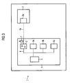
- HMI device 1 shows a schematic representation of a known data processing unit 1, for example, HMI device, in particular HMI display panel.
- HMI device 1 consists of a control unit 5, for example, printed circuit board, and a Display unit 2, for example a display, in particular an LCD display via a data transmission device 4, 4a, for example consisting of a CPU address and data bus and a connected ribbon cable, connected to each other.
- the display 2 points an integrated display controller 2a, the control signals or data transmitted by the printed circuit board 5, evaluates and implements.
- the display 2, in particular LCD display, of the HMI device 1 is thus over the ribbon cable 4a, or also called foil line, driven.
- the printed circuit board 5 has a command unit 3, for example CPU (Central Processing Unit), and other components 8a, 8b, 8c, for example, RAM memory, etc., on, on a data bus 4, such as a CPU address and data bus are connected. Via the data bus 4, the components 8a, 8b, 8c, the printed circuit board 5 is driven by the CPU 3 or exchanged data. Thus, there is constant traffic on the data bus 4 before.
- a command unit 3 for example CPU (Central Processing Unit)
- other components 8a, 8b, 8c for example, RAM memory, etc.
- FIG 1 is further shown that the data bus 4 directly with the ribbon cable 4a and this with the display Controller 2a is connected directly. It is thus no active components between the CPU 3 and the display 2.
- About the ribbon cable 4a are therefore all signals that are transmitted via the data bus 4 and then on the display 2 if the signals or data are not for the display controller 2a and the display 2, but for example the components 8a, 8b, 8c, are determined.
- This traffic is a constant change of signal edges connected to the lines, which has a corresponding noise emission 9 effect. Since it is in the ribbon cable 4a usually around a relatively long pipe that is several inches Depending on the design and cable routing, it can to u. strong, but at least permanent Noise emissions 9.
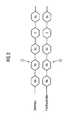
- FIG. 2 shows an exemplary comparison of the data traffic on the data bus 4 and the ribbon cable 4a of the known HMI device 1.
- the rhombuses of the respective data traffic 11, 12 symbolize the data, or signals, for example Control signals via the data bus 4 or the ribbon cable 4a are transmitted.
- the numbers in the diamonds of each Traffic 11, 12 symbolize the respective Receiver, according to the names of FIG 1. It shows that the data traffic 11 on the data bus 4 identical with the traffic being 12, which is via the ribbon cable 4a is applied to the display controller 2a of the display 2.
- this is a decoupling unit 6, for example, a driver module, between the data bus 4 and the ribbon cable 4a installed so that the direct connection between the display 2, in particular the display controller 2a, and the CPU 3 is interrupted. Data or signals which are transmitted via the data bus 4, are therefore not automatically on the display controller 2a at.
- the driver module 6 is both activated and deactivated. According to the invention, a data transmission to the Display controller 2a, for example, from the CPU 3, only in activated state of the driver module 6 possible. In deactivated State of the driver chip 6 are CPU 3 and display 2 physically decoupled. This requires the driver block 6 can be switched to a high-impedance state.
- the decoupling invention Due to the decoupling invention it comes on the Ribbon cable 4a to no signal edge change while For example, the CPU 3 to other components 8a, 8b, 8c, For example, the RAM memory, which also accesses the Noise radiation 9 on the ribbon cable 4 a in these cases is avoided because during CPU access to other components 8a, 8b, 8c, the connection of the CPU 3 to the display 2 quasi interrupted, i. the traffic on the data bus 4 in these cases for the display controller 2a and the Display 2 remains invisible. Signals or data are only then transferred to the display controller 2a when the driver chip 6 is activated, i. only if a transmission of data or signals to the display 2 are provided.
- the driver module 6 activates at a transmission of data necessary for the display controller 2a are determined, even. Is the data transmission terminated to the display controller 2a, the driver module moves automatically turn itself back to the deactivated Status. An external control is not necessary.
- the Control signals for activation or deactivation of the driver module 6 can of course also from the CPU 3 via the data bus 4 are transmitted to the driver module 6.
- the driver module 6 with a resistor 7, for example a pull-up or a Pull-down resistor, coupled.
- a resistor 7 for example a pull-up or a Pull-down resistor
- By combining with Such a pull-up resistor is activated during the transition from State in the deactivated state of the driver block 6 the edge steepness in the signal or data transmission lowered to the display controller. This creates a lower noise emission 9 on the ribbon cable 4a.
- Driver chips 6 are very inexpensive and can very easy with resistors 7, in particular pull-up or Pull-down resistors are combined so that conventional ones Data processing units 1, for example HMI devices, can be retrofitted very easily and inexpensively.
- Noise emissions or interference radiation via the ribbon cable 4a stand so only in the direct data or Signal transmission to the display controller 2a and the display 2, in which case the noise emissions through the Combination of driver chip 6 with pull-up or pull-down resistors 7 is minimized. This also happens to a smaller dispersion of the radiation values at the individual HMI devices of a production series. Furthermore the data bus 4 experiences a lower capacitive load through the display 2 and the ribbon cable 4a. On costly Shielding measures of the ribbon cable 4a, for example by ferrite, can in the inventive arrangement be completely dispensed with. By the invention lower noise emission 9 on the ribbon cable 4a between Display 2, in particular LCD display, and printed circuit board In addition, there are additional cost advantages shortened development times, otherwise in the reduction the disturbance radiation 9 incurred by constructive measures would.
- the inventive HMI device 1 can be particularly advantageous for operating and monitoring of or in industrial plants, In particular, automation systems are used.
- FIG. 4 shows an exemplary comparison of the data traffic on the data bus 4 and the ribbon cable 4a of the invention HMI device 1.
- the numbers in symbolize the diamonds of the respective data traffic 13, 14 again the respective recipients, according to the designations FIG. 1 shows that the data traffic 14, which via the ribbon cable 4a on the display controller 2a of the display 2 is present, compared to the traffic 13, the on the data bus 4 is applied, by the inventive arrangement on the transmission of data to the display controller 2a is limited. All other data transfers are only on Data bus 4 on.
- the present invention relates to a data processing unit 1, for example HMI device, with a Decoupling unit 6, for example a driver module.
- the HMI device 1 consists of a control unit 5, for example, printed circuit board, and a display unit 2, For example, display, via a ribbon cable 4a with each other are connected.
- the driver module according to the invention 6 ensures that noise emissions 9, during data transmission between printed circuit board 5 and display 2 on the Ribbon cables 4a arise to be minimized.
Abstract
Description
Die Erfindung bezieht sich auf eine Datenverarbeitungseinheit mit einer Entkopplungseinheit.The invention relates to a data processing unit with a decoupling unit.
Technische Einrichtungen werden mit Hilfe von digitalen, programmierbaren Datenverarbeitungssystemen gesteuert und bedient. Unter einer technischen Einrichtung wird jede Art von technischen Geräten und Systemen sowohl in Einzelanordnung als auch in einer datentechnischen Vernetzung z.B. über einen Feldbus verstanden. So sind unter technischen Einrichtungen bei einer industriellen Anwendung einzelne Betriebsmittel zu verstehen, wie z.B. Antriebe, Bearbeitungsmaschinen, intelligente Messgeber, Sensoren, u.v.m.. Eine technische Einrichtung kann aber auch eine gesamte Produktionsanlage sein, bei der mit lokal verteilten Betriebsmitteln ein gesamter technischer Prozess betrieben wird, z.B. eine chemische Anlage, eine Fertigungsstraße oder eine verarbeitende Anlage.Technical facilities are using digital, programmable Data processing systems controlled and operated. Under a technical device is any kind of technical devices and systems both in single arrangement as well as in a data networking, e.g. over one Fieldbus understood. So are under technical facilities in an industrial application individual resources too understand, such as Drives, machine tools, intelligent Transducers, sensors, etc. A technical device but can also be an entire production plant, at the with locally distributed resources an entire technical Process is operated, e.g. a chemical plant, a Production line or a processing plant.
Technische Einrichtungen werden mittels digitaler, programmierbarer Datenverarbeitungssystemen gesteuert und bedient, die vielfach als ein Automatisierungssystem bzw. ein Bestandteil davon ausgeführt sind. Dabei weisen Automatisierungssysteme spezielle Geräte auf, welche die Schnittstelle zwischen einem Bediener und dem System bilden. Solche Geräte werden als HMI-Einrichtung bezeichnet, d.h. Human Machine Interface. Weiterhin werden diese Geräte als Vorrichtungen zum "Bedienen- und Beobachten" technischer Einrichtungen bezeichnet, abgekürzt "B+B Geräte". Diese sind den zur direkten Steuerung der technischen Einrichtung dienenden Geräten vorgelagert, z.B. den "PLC" Programmable Logic Controllern. Hierdurch wird eine zentrale Steuereinrichtung entlastet, z.B. eine speicherprogrammierbare Steuerung SPS. Technical facilities are using digital, programmable Controlled and operated data processing systems, often as an automation system or component thereof are executed. In this case have automation systems special devices on which the interface between a server and the system. Such devices will be referred to as HMI device, i. Human Machine Interface. Furthermore, these devices are used as devices for "operating and observing "technical facilities, abbreviated to "B + B devices". These are the ones for direct control upstream of the technical equipment, e.g. the "PLC" Programmable Logic Controllers. This will relieves a central control device, e.g. a programmable logic PLC control.
Der Begriff HMI-Gerät ist ein Oberbegriff und umfasst auch alle zu dieser Gruppe von Geräten gehörigen Komponenten, insbesondere auch ein HMI-Anzeigepanel oder auch kurz HMI-Panel. Als Beispiele für derartige Komponenten sollen z.B. "Operator Panels", die häufig als "Bedienpanels" bzw. kurz als "OP" bezeichnet werden, und als HMI-Geräte bzw. dazugehörige Programmiergeräte eingesetzte Industrie-Personal-Computer IPC genannt werden. HMI-Geräte übernehmen wegen ihrer besonderen Funktionalität z.B. in einem vernetzten Automatisierungssystem Funktionen, die allgemein als Vorgabe und Nachbearbeitung von Daten der zu steuernden technischen Einrichtung angesehen werden können. Diese Funktion wird mit "Supervisor Control and Data Akquisition" (SCADA) bezeichnet. Hierzu wird von einem HMI-Gerät eine spezielle Software ausgeführt. Hiermit werden Funktionen bereitgestellt, die Komfort, Qualität und Sicherheit einer Bedienung durch eine Bedienperson verbessern, z.B. die Übersicht über die zu bedienende Einrichtung und die Fehlerfreiheit von Bedienungen. So können über HMI-Geräte z.B. interaktive Prozessabbilder der zu bedienenden technischen Einrichtung visualisiert und bedient, aber auch projektiert und generiert werden. Hiermit ist einerseits eine selektive Anzeige von Reaktionen der technischen Einrichtung möglich, meist in Form von Messwerten und Meldungen. Andererseits wird es durch gezielte Vorgabe von Bedienhandlungen ermöglicht, die technische Einrichtung in gewünschte Zustände zu überführen. Zusätzlich zu diesen Funktionen "Beobachten und Bedienen" können mit einem HMI-Gerät auch anlagenspezifische Projektierungen möglich sein, z.B. die Projektierung von interaktiven Prozessabbildern.The term HMI device is a generic term and also includes all components belonging to this group of devices, in particular also an HMI display panel or short HMI panel. As examples of such components, e.g. "Operator Panels ", often referred to as" control panels "or short as" OP " and as HMI devices or associated programming devices Used Industrial Personal Computer IPC to be named. HMI devices take over because of their special Functionality, e.g. in a networked automation system Functions, generally as default and postprocessing from data of the technical equipment to be controlled can be. This feature comes with "Supervisor Control and Data Acquisition "(SCADA) HMI device running a special software. Herewith Be provided features that provide comfort, quality and Improve safety of an operator's operation, e.g. the overview of the device to be operated and the accuracy of operations. So can over HMI devices e.g. interactive process images of the users to be served technical equipment visualized and operated, but also be configured and generated. This is on the one hand a selective display of reactions of the technical equipment possible, usually in the form of measured values and messages. on the other hand it is made possible by specific specification of operator actions, the technical equipment in desired conditions to convict. In addition to these functions "Watching and Operate "can also be plant-specific with an HMI device Configurations may be possible, e.g. the project planning of interactive process images.
Eine Datenverarbeitungseinheit, beispielsweise ein HMI-Gerät, insbesondere HMI-Anzeigepanel, setzt sich in der Regel aus einer Steuereinheit, beispielsweise einer Flachbaugruppe, und einer Anzeigeeinheit, beispielsweise einem Display, zusammen. Das Display ist mit der Flachbaugruppe über ein Flachbandkabel, auch Folienleitung genannt, verbunden. Das Display, insbesondere LCD-Display, des HMI-Geräts wird über das Flachbandkabel angesteuert. Dabei weist das Display beispielsweise einen integrierten Display Controller mit integriertem Bildspeicher auf. Dieser Bildspeicher wird bei einer gewünschten Veränderung des Bildinhaltes aktualisiert. Daten von der CPU zum Display Controller brauchen lediglich dann übertragen werden, wenn der Bildinhalt des Displays, insbesondere LCD-Displays, verändert werden soll. Bei gleichbleibendem Bildinhalt können die Daten wie auch etwaige Steuersignale statisch anliegen.A data processing unit, for example an HMI device, In particular, HMI display panel is usually off a control unit, such as a printed circuit board, and a display unit, such as a display together. The display is connected to the printed circuit board via a ribbon cable, also called foil line, connected. The display, in particular LCD display, the HMI device is over the ribbon cable driven. The display shows, for example an integrated display controller with integrated image memory on. This image memory will be at a desired Update of the image content updated. Data from the CPU to the display controller need only then transfer if the image content of the display, in particular LCD displays, to be changed. With the same picture content The data as well as any control signals can be static issue.
Die Flachbaugruppe weist eine Befehlseinheit (Central Processing Unit - CPU) und weitere Komponenten, beispielsweise einen RAM Speicher, auf, die an einen Datenbus, beispielsweise einem CPU-Adress- und Datenbus angeschlossen sind. Über diesen Datenbus werden die Komponenten der Flachbaugruppe von der CPU angesteuert bzw. werden Daten ausgetauscht. Somit liegt ständiger Datenverkehr auf dem Bus vor. Mit diesem Datenverkehr sind ständig Signalflanken auf den Leitungen verbunden, die eine entsprechende Störabstrahlung bewirken.The printed circuit board has a command unit (Central Processing Unit - CPU) and other components, such as a RAM memory, on, which is connected to a data bus, for example a CPU address and data bus are connected. About this Data bus are the components of the printed circuit board of the CPU is controlled or data is exchanged. Consequently There is constant traffic on the bus. With this traffic there are constantly signal edges on the lines, which cause a corresponding noise emission.
Bei gegenwärtig verfügbaren HMI-Geräten ist in der Regel der Display Controller über das Flachbandkabel direkt mit dem CPU-Adress- und Datenbus verbunden. Es sind somit keine aktiven Bauteile zwischen der CPU und dem Display. Über das Flachbandkabel liegen demnach alle Signale, die über den Datenbus übertragen werden am Display an, auch wenn die Signale bzw. Daten, die über den CPU-Adress- und Datenbus übertragen werden, nicht für den Display-Controller bestimmt sind. Da es sich bei der Leitung, insbesondere Flachbandkabel, meist um eine relativ lange Leitung, die mehrere Zentimeter umfassen kann, handelt, kommt es je nach Konstruktion und Kabelverlegung zu u.U. starken zumindest aber permanenten Störabstrahlungen.Currently available HMI devices typically have the Display Controller via the ribbon cable directly to the CPU address and data bus connected. They are therefore not active Components between the CPU and the display. About the Ribbon cables are therefore all signals that are over the data bus be transmitted on the display, even if the signals or data transmitted via the CPU address and data bus are not intended for the display controller. Because it in the line, especially ribbon cable, usually to a relatively long pipe that covers several inches can act, it depends on the construction and cable laying to u. strong but at least permanent noise emission.
Nachteil dieser Anordnung ist insbesondere, dass die Kabelverlegung von HMI-Gerät zu HMI-Gerät einer Bauserie zwischen Display und CPU unterschiedlich erfolgt, sodass die Störabstrahlung nicht gleich ist. Dadurch sind verschiedene, zusätzliche und kostenaufwändige Maßnahmen, wie beispielsweise eine Ferritabschirmung über das Flachbandkabel, notwendig, um einen entsprechend hohen Störabstand zu gewährleisten.Disadvantage of this arrangement is in particular that the cable laying from HMI device to HMI device of a construction series between Display and CPU are different, so the noise emission is not the same. There are several, additional and costly measures, such as a ferrite shield over the ribbon cable, necessary to to ensure a correspondingly high signal to noise ratio.
Aufgabe der vorliegenden Erfindung ist es, eine Datenverarbeitungseinheit, beispielsweise HMI-Gerät anzugeben, bei der die Ansteuerung der Anzeigeeinheit, beispielsweise Display, durch die Steuereinheit, beispielsweise Flachbaugruppe, verbessert wird.The object of the present invention is to provide a data processing unit, For example, specify HMI device in which the control of the display unit, for example display, by the control unit, such as printed circuit board, improved becomes.
Diese Aufgabe wird durch eine Datenverarbeitungseinheit mit wenigstens einer Anzeigeeinheit und einer Befehlseinheit, wobei die Befehlseinheit und die Anzeigeeinheit mittels einer Datenübertragungsvorrichtung zur Übermittlung von Daten miteinander verbunden sind, mit wenigstens einer Entkopplungseinheit zwischen der Befehlseinheit und der Anzeigeeinheit gelöst.This task is performed by a data processing unit at least one display unit and a command unit, wherein the command unit and the display unit by means of a Data transmission device for communicating data with each other are connected, with at least one decoupling unit between the command unit and the display unit solved.
Vorteil dieser Anordnung ist insbesondere, dass dadurch die Anzeigeeinheit, beispielsweise das Display, insbesondere der Display-Controller keine direkte Verbindung zur Befehlseinheit, beispielsweise CPU, hat, da die Datenübertragungsvorrichtung, die beispielsweise aus einem CPU-Adress- und Datenbus und einem angeschlossenen Flachbandkabel besteht, unterbrochen ist. Daten bzw. Signale die über den Datenbus übertragen werden, liegen somit nicht automatisch am Display-Controller an.Advantage of this arrangement is in particular that thereby the Display unit, such as the display, in particular the Display controller no direct connection to the command unit, For example, CPU, since the data transfer device, for example, a CPU address and data bus and a connected ribbon cable is interrupted is. Data or signals transmitted via the data bus are not automatically on the display controller at.
Nach einer bevorzugten Ausführungsform der Erfindung ist die Entkopplungseinheit aktivierbar oder deaktivierbar. Darüber hinaus ist die Datenverarbeitungseinheit zur Datenübertragung zwischen der Befehlseinheit und der Anzeigeeinheit bei aktivierter Entkopplungseinheit vorgesehen. Weiterhin sind die Befehlseinheit und die Anzeigeeinheit bei deaktivierter Entkopplungseinheit physikalisch entkoppelt. Dazu nimmt die Entkopplungseinheit einen hochohmigen Zustand an. According to a preferred embodiment of the invention is the Decoupling unit can be activated or deactivated. About that In addition, the data processing unit is for data transmission between the command unit and the display unit when activated Decoupling provided. Furthermore, the Command unit and the display unit with deactivated decoupling unit physically decoupled. This is done by the decoupling unit a high-impedance state.
Dadurch wird gewährleistet, dass Signale bzw. Daten, die über den Datenbus übertragen werden, nur dann zur Anzeigeeinheit, beispielsweise Display-Controller übertragen werden, wenn die Entkopplungseinheit aktiviert ist, d.h. nur dann, wenn die Daten bzw. Signale auch für das Display vorgesehen sind. Bei der Übertragung anderer Daten bleibt die Entkopplungseinheit deaktiviert, also im hochohmigen Zustand, d.h. der Datenverkehr auf dem CPU-Adress- und Datenbus bleibt für den Display-Controller unsichtbar, da in diesen Fällen keine physikalische Verbindung zwischen Befehlseinheit, beispielsweise CPU, und Anzeigeeinheit, beispielsweise Display, insbesondere Display-Controller existiert. Dadurch entsteht in diesen Fällen auch keine Störstrahlung auf dem Flachbandkabel.This ensures that signals or data over the data bus, only to the display unit, For example, display controllers are transferred when the Decoupling unit is activated, i. only if the Data or signals are also provided for the display. at the decoupling unit remains the transfer of other data deactivated, ie in the high-resistance state, i. the traffic on the CPU address and data bus remains for the display controller invisible, since in these cases no physical Connection between command unit, for example CPU, and display unit, for example display, in particular display controller exist. This creates in these cases no interference on the ribbon cable.
Nach einer weiteren besonders vorteilhaften Ausführungsform der Erfindung weist die Entkopplungseinheit Mittel auf, die eine Selbstaktivierung der Entkopplungseinheit bei einer Übertragung von Daten, welche für die Anzeigeeinheit bestimmt sind, bewirken und/oder eine Deaktivierung der Entkopplungseinheit bewirken, wenn die Datenübertragung an die Anzeigeeinheit beendet ist. Dies hat den Vorteil dass dies beispielsweise nicht extern gesteuert werden muss, sondern automatisch vor sich geht.According to another particularly advantageous embodiment According to the invention, the decoupling unit has means which a self-activation of the decoupling unit in a transmission of data intended for the display unit are, cause and / or deactivation of the decoupling unit cause when data transfer to the display unit finished. This has the advantage that this, for example does not have to be controlled externally, but automatically is going on.
Nach einer weiteren besonders vorteilhaften Ausführungsform der Erfindung ist die Entkopplungseinheit ein Treiberbaustein. Darüber hinaus weist die Entkopplungseinheit wenigstens einen Widerstand auf, wobei der Widerstand ein Pull-Upoder ein Pull-Down-Widerstand ist. Durch die Kombination mit solchen Widerständen wird im aktivierten Zustand die Flankensteilheit bei der Signal- bzw. Datenübertragung an die Anzeigeeinheit erniedrigt. Dadurch entsteht eine geringere Störabstrahlung auf dem Flachbandkabel. Treiberbausteine sind sehr kostengünstig und können sehr einfach mit Widerständen, insbesondere Pull-Up- oder Pull-Down-Widerständen kombiniert werden, so dass herkömmliche Datenverarbeitungseinheiten, beispielsweise HMI-Geräte sehr leicht und kostengünstig nachgerüstet werden können.According to another particularly advantageous embodiment According to the invention, the decoupling unit is a driver module. In addition, the decoupling unit at least a resistor, wherein the resistor is a pull-up or is a pull-down resistor. By combining with such resistors in the activated state, the edge steepness in the signal or data transmission to the display unit decreased. This results in a lower noise emission on the ribbon cable. Driver chips are very inexpensive and can be very easily with resistors, in particular Combined pull-up or pull-down resistors so that traditional computing devices, For example, HMI devices retrofitted very easily and inexpensively can be.
Störabstrahlungen bzw. Störstrahlungen über das Flachbandkabel einstehen also nur noch bei der direkten Daten- bzw. Signalübertragung an die Anzeigeeinheit, wobei die Störabstrahlungen durch die Kombination des Treiberbausteins mit Pull-Up- oder Pull-Down-Widerständen darüber hinaus minimiert wird. Dadurch kommt es ebenfalls zu einer geringeren Streuung der Abstrahlwerte bei den einzelnen HMI-Geräten einer Serie. Darüber hinaus erfährt der CPU-Daten-Adressbus eine geringere kapazitive Belastung durch das LCD-Display und das Flachbandkabel. Auf kostenintensive Abschirmungsmaßnahmen der Flachbandkabel, beispielsweise durch Ferrite, kann in der erfindungsgemäßen Anordnung gänzlich verzichtet werden. Durch die erfindungsgemäß geringere Störabstrahlung auf dem Flachbandkabel zwischen LCD-Display und beispielsweise Flachbaugruppe kommt es darüber hinaus zu weiteren Kostenvorteilen durch verkürzte Entwicklungszeiten, die ansonsten bei der Reduzierung der Störabstrahlung anfallen würden.Noise emissions or interference radiation via the ribbon cable So only stand in the direct data or signal transmission to the display unit, wherein the noise emissions by combining the driver module with pull-up or minimized pull-down resistors beyond that becomes. This also leads to a lower dispersion the emission values for the individual HMI devices of a series. In addition, the CPU data address bus experiences less capacitive loading through the LCD display and the ribbon cable. On cost-intensive shielding measures of the ribbon cables, for example, by ferrites, in the inventive Arrangement to be omitted altogether. By the According to the invention lower noise radiation on the ribbon cable between LCD display and, for example, printed circuit board In addition, there are further cost advantages shortened development times, otherwise in the reduction the noise emission would occur.
Nach einer weiteren besonders vorteilhaften Ausführungsform der Erfindung ist die Datenverarbeitungseinheit ein HMI-Gerät, welches darüber hinaus zum Einsatz in einem Automatisierungssystem vorgesehen ist. Besonders vorteilhaft kann es zum Bedienen und Beobachten von bzw. in Industrieanlagen, insbesondere Automatisierungsanlagen eingesetzt werden.According to another particularly advantageous embodiment invention, the data processing unit is an HMI device, which is also used in an automation system is provided. It can be particularly advantageous for operating and monitoring of or in industrial plants, In particular, automation systems are used.
Besonders vorteilhaft ist der Betrieb eines Automatisierungssystems mit wenigstens einer erfindungsgemäßen Datenverarbeitungseinheit im industriellen Umfeld.Particularly advantageous is the operation of an automation system with at least one data processing unit according to the invention in the industrial environment.
Im Weiteren werden bevorzugte Ausführungsbeispiele der Erfindung mit Bezugnahme auf die Zeichnungen näher erläutert. Soweit in unterschiedlichen Figuren Elemente mit gleichen Funktionalitäten beschrieben sind, sind diese mit gleichen Bezugszeichen gekennzeichnet. Es zeigen:
- FIG 1
- eine schematische Darstellung einer bekannten Datenverarbeitungseinheit, beispielsweise HMI-Gerät,
- FIG 2
- einen beispielhaften Vergleich des Datenverkehrs auf dem Datenbus und dem Flachbandkabel des bekannten HMI-Geräts,
- FIG 3
- eine schematische Darstellung einer erfindungsgemäßen Datenverarbeitungseinheit, beispielsweise HMI-Gerät und
- FIG 4
- einen beispielhaften Vergleich des Datenverkehrs auf dem Datenbus und dem Flachbandkabel des erfindungsgemäßen HMI-Geräts
- FIG. 1
- a schematic representation of a known data processing unit, such as HMI device,
- FIG. 2
- an exemplary comparison of the traffic on the data bus and the ribbon cable of the known HMI device,
- FIG. 3
- a schematic representation of a data processing unit according to the invention, for example, HMI device and
- FIG. 4
- an exemplary comparison of the data traffic on the data bus and the ribbon cable of the HMI device according to the invention
FIG 1 zeigt eine schematische Darstellung einer bekannten Datenverarbeitungseinheit
1, beispielsweise HMI-Gerät, insbesondere
HMI-Anzeigepanel. Ein solches HMI-Gerät 1 besteht aus
einer Steuereinheit 5, beispielsweise Flachbaugruppe, und einer
Anzeigeeinheit 2, beispielsweise einem Display, insbesondere
einem LCD-Display, die über eine Datenübertragungsvorrichtung
4, 4a, beispielsweise bestehend aus einem CPU-Adress-
und Datenbus und einem angeschlossenen Flachbandkabel,
miteinander verbunden sind. Das Display 2 weist dabei
einen integrierten Display-Controller 2a auf, der Steuersignale
bzw. Daten, die von der Flachbaugruppe 5 übertragen werden,
auswertet und umsetzt. Das Display 2, insbesondere LCD-Display,
des HMI-Geräts 1 wird also über das Flachbandkabel
4a, oder auch Folienleitung genannt, angesteuert.1 shows a schematic representation of a known
Die Flachbaugruppe 5 weist eine Befehlseinheit 3, beispielsweise
CPU (Central Processing Unit), und weitere Komponenten
8a, 8b, 8c, beispielsweise RAM Speicher, etc., auf, die an
einem Datenbus 4, beispielsweise einem CPU-Adress- und Datenbus
angeschlossen sind. Über den Datenbus 4 werden die Komponenten
8a, 8b, 8c, der Flachbaugruppe 5 von der CPU 3 angesteuert
bzw. Daten ausgetauscht. Somit liegt ständiger Datenverkehr
auf dem Datenbus 4 vor.The printed circuit board 5 has a command unit 3, for example
CPU (Central Processing Unit), and
In der FIG 1 ist weiterhin gezeigt, dass der Datenbus 4 direkt
mit dem Flachbandkabel 4a und dieses mit dem Display
Controller 2a direkt verbunden ist. Es befinden sich somit
keine aktiven Bauteile zwischen der CPU 3 und dem Display 2.
Über das Flachbandkabel 4a liegen demnach alle Signale, die
über den Datenbus 4 übertragen werden auch dann am Display 2
an, wenn die Signale bzw. Daten nicht für den Display-Controller
2a bzw. das Display 2, sondern beispielsweise für
die Komponenten 8a, 8b, 8c, bestimmt sind. Somit liegt der
ständige Datenverkehr auch am Display-Controller 2a an. Mit
diesem Datenverkehr ist ein ständiger Wechsel von Signalflanken
auf den Leitungen verbunden, die eine entsprechende Störabstrahlung
9 bewirken. Da es sich bei dem Flachbandkabel 4a
meist um eine relativ lange Leitung, die mehrere Zentimeter
umfassen kann, handelt, kommt es je nach Konstruktion und Kabelverlegung
zu u.U. starken, zumindest aber permanenten
Störabstrahlungen 9.In FIG 1 is further shown that the data bus 4 directly
with the
FIG 2 zeigt einen beispielhaften Vergleich des Datenverkehrs
auf dem Datenbus 4 und dem Flachbandkabel 4a des bekannten
HMI-Geräts 1. Die Rauten des jeweiligen Datenverkehrs 11, 12
symbolisieren dabei die Daten, bzw. Signale, beispielsweise
Steuersignale, die über den Datenbus 4 bzw. das Flachbandkabel
4a übermittelt werden. Die Zahlen in den Rauten des jeweiligen
Datenverkehrs 11, 12 symbolisieren die jeweiligen
Empfänger, gemäß der Bezeichnungen aus der FIG 1. Dabei zeigt
sich dass der Datenverkehr 11 auf dem Datenbus 4 identisch
mit dem Datenverkehr 12 ist, welcher über das Flachbandkabel
4a am Display-Controller 2a des Displays 2 anliegt.FIG. 2 shows an exemplary comparison of the data traffic
on the data bus 4 and the
FIG 3 zeigt eine schematische Darstellung eines erfindungsgemäßen
HMI-Geräts 1. Dabei wird erfindungsgemäß eine Entkopplungseinheit
6, beispielsweise ein Treiberbaustein, zwischen
dem Datenbus 4 und dem Flachbandkabel 4a eingebaut, so dass
die direkte Verbindung zwischen dem Display 2, insbesondere
dem Display-Controller 2a, und der CPU 3 unterbrochen ist.
Daten bzw. Signale, die über den Datenbus 4 übertragen werden,
liegen somit nicht automatisch am Display-Controller 2a
an. Der Treiberbaustein 6 ist sowohl aktivierbar als auch deaktivierbar.
Erfindungsgemäß ist eine Datenübertragung an den
Display-Controller 2a, beispielsweise von der CPU 3, nur im
aktivierten Zustand des Treiberbausteins 6 möglich. Im deaktivierten
Zustand des Treiberbausteins 6 sind CPU 3 und Display
2 physikalisch entkoppelt. Dazu muss der Treiberbaustein
6 in einen hochohmigen Zustand geschaltet werden können.3 shows a schematic representation of an
Durch die erfindungsgemäße Entkopplung kommt es auf dem
Flachbandkabel 4a zu keinem Signalflankenwechsel, während
beispielsweise die CPU 3 auf andere Komponenten 8a, 8b, 8c,
beispielsweise den RAM Speicher, zugreift, wodurch auch die
Störabstrahlung 9 auf dem Flachbandkabel 4a in diesen Fällen
vermieden wird, da während des CPU-Zugriffs auf andere Komponenten
8a, 8b, 8c, die Verbindung der CPU 3 zum Display 2
quasi unterbrochen ist, d.h. der Datenverkehr auf dem Datenbus
4 in diesen Fällen für den Display-Controller 2a bzw. das
Display 2 unsichtbar bleibt. Signale bzw. Daten werden nur
dann zum Display-Controller 2a übertragen, wenn der Treiberbaustein
6 aktiviert ist, d.h. nur dann, wenn eine Übertragung
von Daten bzw. Signale an das Display 2 vorgesehen sind.Due to the decoupling invention it comes on the
Vorteilhafterweise aktiviert sich der Treiberbaustein 6 bei
einer Übertragung von Daten, welche für den Display-Controller
2a bestimmt sind, selbst. Ist die Datenübertragung
an den Display-Controller 2a beendet, versetzt sich der Treiberbaustein
automatisch selbst wieder in den deaktivierten
Zustand. Eine externe Steuerung ist dazu nicht notwendig. Die
Steuersignale zur Aktivierung bzw. Deaktivierung des Treiberbausteins
6 können selbstverständlich auch von der CPU 3 über
den Datenbus 4 an den Treiberbaustein 6 übermittelt werden. Advantageously, the
Darüber hinaus ist der Treiberbaustein 6 erfindungsgemäß mit
einem Widerstand 7, beispielsweise einem Pull-Up- oder einem
Pull-Down-Widerstand, gekoppelt. Durch die Kombination mit
einem solchen Pull-Up-Widerstand wird beim Übergang vom aktivierten
Zustand in den deaktivierten Zustand des Treiberbausteins
6 die Flankensteilheit bei der Signal- bzw. Datenübertragung
an den Display-Controller erniedrigt. Dadurch entsteht
eine geringere Störabstrahlung 9 auf dem Flachbandkabel
4a. Treiberbausteine 6 sind sehr kostengünstig und können
sehr einfach mit Widerständen 7, insbesondere Pull-Up- oder
Pull-Down-Widerständen kombiniert werden, so dass herkömmliche
Datenverarbeitungseinheiten 1, beispielsweise HMI-Geräte,
sehr leicht und kostengünstig nachgerüstet werden können.In addition, the
Störabstrahlungen bzw. Störstrahlungen über das Flachbandkabel
4a einstehen also nur noch bei der direkten Daten- bzw.
Signalübertragung an den Display-Controller 2a bzw. das Display
2, wobei in diesem Fall die Störabstrahlungen durch die
Kombination des Treiberbausteins 6 mit Pull-Up- oder Pull-Down-Widerständen
7 minimiert wird. Dadurch kommt es ebenfalls
zu einer geringeren Streuung der Abstrahlwerte bei den
einzelnen HMI-Geräten einer Fertigungsserie. Darüber hinaus
erfährt der Datenbus 4 eine geringere kapazitive Belastung
durch das Display 2 und das Flachbandkabel 4a. Auf kostenintensive
Abschirmungsmaßnahmen des Flachbandkabels 4a, beispielsweise
durch Ferrite, kann in der erfindungsgemäßen Anordnung
gänzlich verzichtet werden. Durch die erfindungsgemäß
geringere Störabstrahlung 9 auf dem Flachbandkabel 4a zwischen
Display 2, insbesondere LCD-Display, und Flachbaugruppe
5 kommt es darüber hinaus zu weiteren Kostenvorteilen durch
verkürzte Entwicklungszeiten, die ansonsten bei der Reduzierung
der Störabstrahlung 9 durch konstruktive Maßnahmen anfallen
würden.Noise emissions or interference radiation via the
Besonders vorteilhaft kann das erfindungsgemäße HMI-Gerät 1
zum Bedienen und Beobachten von bzw. in Industrieanlagen,
insbesondere Automatisierungsanlagen eingesetzt werden. The
FIG 4 zeigt einen beispielhaften Vergleich des Datenverkehrs
auf dem Datenbus 4 und dem Flachbandkabel 4a des erfindungsgemäßen
HMI-Geräts 1. Die Rauten des jeweiligen Datenverkehrs
11, 12 symbolisieren dabei gemäß FIG 2 die Daten, bzw. Signale,
beispielsweise Steuersignale, die über den Datenbus 4
bzw. das Flachbandkabel 4a übermittelt werden. Die Zahlen in
den Rauten des jeweiligen Datenverkehrs 13, 14 symbolisieren
wieder die jeweiligen Empfänger, gemäß der Bezeichnungen aus
der FIG 1. Dabei zeigt sich dass der Datenverkehr 14, welcher
über das Flachbandkabel 4a am Display-Controller 2a des Displays
2 anliegt, im Vergleich zum Datenverkehr 13, der auf
dem Datenbus 4 anliegt, durch die erfindungsgemäße Anordnung
auf die Übertragung von Daten an den Display-Controller 2a
beschränkt ist. Alle anderen Datenübertragungen liegen nur am
Datenbus 4 an.4 shows an exemplary comparison of the data traffic
on the data bus 4 and the
Zusammengefasst betrifft die vorliegende Erfindung eine Datenverarbeitungseinheit
1, beispielsweise HMI-Gerät, mit einer
Entkopplungseinheit 6, beispielsweise einem Treiberbaustein.
Das HMI-Gerät 1 besteht aus einer Steuereinheit 5,
beispielsweise Flachbaugruppe, und einer Anzeigeeinheit 2,
beispielsweise Display, die über ein Flachbandkabel 4a miteinander
verbunden sind. Der erfindungsgemäße Treiberbaustein
6 sorgt dafür, dass Störabstrahlungen 9, die bei der Datenübertragung
zwischen Flachbaugruppe 5 und Display 2 auf dem
Flachbandkabel 4a entstehen, minimiert werden.In summary, the present invention relates to a
Claims (13)
dadurch gekennzeichnet, dass die Entkopplungseinheit (6) aktivierbar oder deaktivierbar ist.Data processing unit according to claim 1,
characterized in that the decoupling unit (6) can be activated or deactivated.
dadurch gekennzeichnet, dass die Datenverarbeitungseinheit (1) zur Datenübertragung zwischen der Befehlseinheit (3) und der Anzeigeeinheit (2) bei aktivierter Entkopplungseinheit (6) vorgesehen ist.Data processing unit according to one of claims 1 or 2,
characterized in that the data processing unit (1) is provided for data transmission between the command unit (3) and the display unit (2) when the decoupling unit (6) is activated.
dadurch gekennzeichnet, dass die Befehlseinheit (3) und die Anzeigeeinheit (2) bei deaktivierter Entkopplungseinheit (6) physikalisch entkoppelt sind.Data processing unit according to one of the preceding claims,
characterized in that the command unit (3) and the display unit (2) are physically decoupled when the decoupling unit (6) is deactivated.
dadurch gekennzeichnet, dass die Entkopplungseinheit (6) einen hochohmigen Zustand annimmt.Data processing unit according to one of the preceding claims,
characterized in that the decoupling unit (6) assumes a high-impedance state.
dadurch gekennzeichnet, dass die Entkopplungseinheit (6) Mittel aufweist, die eine Selbstaktivierung der Entkopplungseinheit (6) bei einer Übertragung von Daten, welche für die Anzeigeeinheit (2) bestimmt sind, bewirken und/oder eine Deaktivierung der Entkopplungseinheit (6) bewirken, wenn die Datenübertragung an die Anzeigeeinheit (2) beendet ist.Data processing unit according to one of the preceding claims,
characterized in that the decoupling unit (6) comprises means which cause a self-activation of the decoupling unit (6) in a transmission of data, which are intended for the display unit (2), and / or cause deactivation of the decoupling unit (6), if the data transmission to the display unit (2) is completed.
dadurch gekennzeichnet, dass die Entkopplungseinheit (6) ein Treiberbaustein ist.Data processing unit according to one of the preceding claims,
characterized in that the decoupling unit (6) is a driver module.
dadurch gekennzeichnet, dass die Entkopplungseinheit (6) wenigstens einen Widerstand (7) aufweist.Data processing unit according to one of the preceding claims,
characterized in that the decoupling unit (6) has at least one resistor (7).
dadurch gekennzeichnet, dass der Widerstand (7) ein Pull-Up- oder ein Pull-Down-Widerstand ist.Data processing unit according to claim 8,
characterized in that the resistor (7) is a pull-up or a pull-down resistor.
dadurch gekennzeichnet, dass die Datenverarbeitungseinheit (1) ein HMI-Gerät ist.Data processing unit according to one of the preceding claims,
characterized in that the data processing unit (1) is an HMI device.
dadurch gekennzeichnet, dass die Anzeigeeinheit (2) ein LCD-Display ist.Data processing unit according to one of the preceding claims,
characterized in that the display unit (2) is an LCD display.
dadurch gekennzeichnet, dass die Datenverarbeitungseinheit (1) zum Einsatz in einem Automatisierungssystem vorgesehen ist.Data processing unit according to one of the preceding claims,
characterized in that the data processing unit (1) is provided for use in an automation system.
Applications Claiming Priority (4)
| Application Number | Priority Date | Filing Date | Title |
|---|---|---|---|
| DE10344864A DE10344864A1 (en) | 2003-09-26 | 2003-09-26 | Data-processing unit for a human-machine interface has a decoupling unit like a driver component, a printed circuit module and a display device |
| DE20314961U | 2003-09-26 | ||
| DE20314961U DE20314961U1 (en) | 2003-09-26 | 2003-09-26 | Data processing unit e.g. human-machine interface for automation system, has decoupling unit connected between command unit and display unit |
| DE10344864 | 2003-09-26 |
Publications (3)
| Publication Number | Publication Date |
|---|---|
| EP1519257A2 true EP1519257A2 (en) | 2005-03-30 |
| EP1519257A3 EP1519257A3 (en) | 2009-03-04 |
| EP1519257B1 EP1519257B1 (en) | 2013-04-24 |
Family
ID=34195774
Family Applications (1)
| Application Number | Title | Priority Date | Filing Date |
|---|---|---|---|
| EP04022728.2A Expired - Fee Related EP1519257B1 (en) | 2003-09-26 | 2004-09-23 | Data processing unit with uncoupling unit |
Country Status (1)
| Country | Link |
|---|---|
| EP (1) | EP1519257B1 (en) |
Cited By (1)
| Publication number | Priority date | Publication date | Assignee | Title |
|---|---|---|---|---|
| WO2013120443A1 (en) * | 2012-02-13 | 2013-08-22 | 施耐德电器工业公司 | Human-machine interface apparatus and control cabinet comprising same |
Citations (4)
| Publication number | Priority date | Publication date | Assignee | Title |
|---|---|---|---|---|
| GB2152761A (en) | 1983-12-15 | 1985-08-07 | Citizen Watch Co Ltd | A liquid crystal display device |
| US6237056B1 (en) | 2000-07-14 | 2001-05-22 | Videon, Inc. | Apparatus and method for high speed board-to board ribbon cable data transfer |
| US20010050659A1 (en) | 2000-06-12 | 2001-12-13 | Yuji Sato | Image display system and display device |
| US6510525B1 (en) | 1999-04-26 | 2003-01-21 | Mediaq, Inc. | Method and apparatus to power up an integrated device from a low power state |
-
2004
- 2004-09-23 EP EP04022728.2A patent/EP1519257B1/en not_active Expired - Fee Related
Patent Citations (4)
| Publication number | Priority date | Publication date | Assignee | Title |
|---|---|---|---|---|
| GB2152761A (en) | 1983-12-15 | 1985-08-07 | Citizen Watch Co Ltd | A liquid crystal display device |
| US6510525B1 (en) | 1999-04-26 | 2003-01-21 | Mediaq, Inc. | Method and apparatus to power up an integrated device from a low power state |
| US20010050659A1 (en) | 2000-06-12 | 2001-12-13 | Yuji Sato | Image display system and display device |
| US6237056B1 (en) | 2000-07-14 | 2001-05-22 | Videon, Inc. | Apparatus and method for high speed board-to board ribbon cable data transfer |
Cited By (3)
| Publication number | Priority date | Publication date | Assignee | Title |
|---|---|---|---|---|
| WO2013120443A1 (en) * | 2012-02-13 | 2013-08-22 | 施耐德电器工业公司 | Human-machine interface apparatus and control cabinet comprising same |
| EP2804062A4 (en) * | 2012-02-13 | 2015-08-19 | Schneider Electric Ind Sas | Human-machine interface apparatus and control cabinet comprising same |
| US20160018801A1 (en) * | 2012-02-13 | 2016-01-21 | Schneider Electric Industries Sas | Human-machine interface apparatus and control cabinet comprising same |
Also Published As
| Publication number | Publication date |
|---|---|
| EP1519257A3 (en) | 2009-03-04 |
| EP1519257B1 (en) | 2013-04-24 |
Similar Documents
| Publication | Publication Date | Title |
|---|---|---|
| EP1279076B1 (en) | Control method and industrial production installation with web control system | |
| EP1415208A1 (en) | Method and process management system for the operation of a technical plant | |
| EP2247987A1 (en) | Method for operating a field device | |
| DE10211939A1 (en) | Coupling device for coupling devices to a bus system | |
| DE10203370A1 (en) | Procedure for controlling a window-oriented user interface and an HMI device for performing the procedure | |
| DE102016000126B4 (en) | Serial bus system with coupling modules | |
| EP1431877A2 (en) | Parameterizing-/diagnostic system for a field device | |
| EP2016470A1 (en) | Operator panel for exchanging data with a field device in an automation system | |
| EP3014816B1 (en) | Field bus coupler for connecting input/output modules to a field bus, and method of operation for a field bus coupler | |
| EP3637205A1 (en) | Image activation on an operator station client | |
| EP0782722B1 (en) | Process and device for controlling and activating sensors and/or actuators that are linked by a bus system | |
| DE102011077318B4 (en) | Simulation system, method for carrying out a simulation, control system and computer program product | |
| DE102007029321B4 (en) | Method for operating a field device in a user-friendly mode | |
| EP1779206B1 (en) | Periphery unit for an automatic device | |
| EP1251416B1 (en) | Diagnostic device for a field-bus with control independent information transfer | |
| DE19543826A1 (en) | Simulator unit for simulating a peripheral unit of a modular programmable logic controller | |
| DE102007063291A1 (en) | safety control | |
| EP1695159B1 (en) | Redundant control system | |
| EP1748334A1 (en) | Method and device for supervising a transmission medium | |
| EP1519257B1 (en) | Data processing unit with uncoupling unit | |
| EP2942686B1 (en) | Control and data transmission system for transmission of safety-related data via a communication medium | |
| DE102005007477B4 (en) | Programmable control for machine and / or plant automation with standard control and safety functions and communication with a safety I / O and method for operating the programmable controller | |
| EP1493067B1 (en) | Method for projecting and/or operating an automation device | |
| DE69918829T2 (en) | CONTROL SYSTEM FOR CONTROLLING PROCESS DEVICES | |
| EP3141970B1 (en) | Decentralized periphery |
Legal Events
| Date | Code | Title | Description |
|---|---|---|---|
| PUAI | Public reference made under article 153(3) epc to a published international application that has entered the european phase |
Free format text: ORIGINAL CODE: 0009012 |
|
| AK | Designated contracting states |
Kind code of ref document: A2 Designated state(s): AT BE BG CH CY CZ DE DK EE ES FI FR GB GR HU IE IT LI LU MC NL PL PT RO SE SI SK TR |
|
| AX | Request for extension of the european patent |
Extension state: AL HR LT LV MK |
|
| PUAL | Search report despatched |
Free format text: ORIGINAL CODE: 0009013 |
|
| AK | Designated contracting states |
Kind code of ref document: A3 Designated state(s): AT BE BG CH CY CZ DE DK EE ES FI FR GB GR HU IE IT LI LU MC NL PL PT RO SE SI SK TR |
|
| AX | Request for extension of the european patent |
Extension state: AL HR LT LV MK |
|
| 17P | Request for examination filed |
Effective date: 20090810 |
|
| 17Q | First examination report despatched |
Effective date: 20090902 |
|
| AKX | Designation fees paid |
Designated state(s): DE FR GB IT |
|
| GRAP | Despatch of communication of intention to grant a patent |
Free format text: ORIGINAL CODE: EPIDOSNIGR1 |
|
| GRAS | Grant fee paid |
Free format text: ORIGINAL CODE: EPIDOSNIGR3 |
|
| RAP1 | Party data changed (applicant data changed or rights of an application transferred) |
Owner name: SIEMENS AKTIENGESELLSCHAFT |
|
| GRAA | (expected) grant |
Free format text: ORIGINAL CODE: 0009210 |
|
| AK | Designated contracting states |
Kind code of ref document: B1 Designated state(s): DE FR GB IT |
|
| REG | Reference to a national code |
Ref country code: GB Ref legal event code: FG4D Free format text: NOT ENGLISH |
|
| REG | Reference to a national code |
Ref country code: DE Ref legal event code: R096 Ref document number: 502004014129 Country of ref document: DE Effective date: 20130620 |
|
| PGFP | Annual fee paid to national office [announced via postgrant information from national office to epo] |
Ref country code: FR Payment date: 20130924 Year of fee payment: 10 Ref country code: GB Payment date: 20130911 Year of fee payment: 10 |
|
| PGFP | Annual fee paid to national office [announced via postgrant information from national office to epo] |
Ref country code: IT Payment date: 20130921 Year of fee payment: 10 |
|
| PGFP | Annual fee paid to national office [announced via postgrant information from national office to epo] |
Ref country code: DE Payment date: 20131120 Year of fee payment: 10 |
|
| PLBE | No opposition filed within time limit |
Free format text: ORIGINAL CODE: 0009261 |
|
| STAA | Information on the status of an ep patent application or granted ep patent |
Free format text: STATUS: NO OPPOSITION FILED WITHIN TIME LIMIT |
|
| 26N | No opposition filed |
Effective date: 20140127 |
|
| REG | Reference to a national code |
Ref country code: DE Ref legal event code: R097 Ref document number: 502004014129 Country of ref document: DE Effective date: 20140127 |
|
| REG | Reference to a national code |
Ref country code: DE Ref legal event code: R119 Ref document number: 502004014129 Country of ref document: DE |
|
| GBPC | Gb: european patent ceased through non-payment of renewal fee |
Effective date: 20140923 |
|
| REG | Reference to a national code |
Ref country code: DE Ref legal event code: R119 Ref document number: 502004014129 Country of ref document: DE Effective date: 20150401 |
|
| REG | Reference to a national code |
Ref country code: FR Ref legal event code: ST Effective date: 20150529 |
|
| PG25 | Lapsed in a contracting state [announced via postgrant information from national office to epo] |
Ref country code: DE Free format text: LAPSE BECAUSE OF NON-PAYMENT OF DUE FEES Effective date: 20150401 Ref country code: GB Free format text: LAPSE BECAUSE OF NON-PAYMENT OF DUE FEES Effective date: 20140923 |
|
| PG25 | Lapsed in a contracting state [announced via postgrant information from national office to epo] |
Ref country code: FR Free format text: LAPSE BECAUSE OF NON-PAYMENT OF DUE FEES Effective date: 20140930 Ref country code: IT Free format text: LAPSE BECAUSE OF NON-PAYMENT OF DUE FEES Effective date: 20140923 |