EP1519499A1 - System and method for generating multilevel coded optical signals - Google Patents
System and method for generating multilevel coded optical signals Download PDFInfo
- Publication number
- EP1519499A1 EP1519499A1 EP04255617A EP04255617A EP1519499A1 EP 1519499 A1 EP1519499 A1 EP 1519499A1 EP 04255617 A EP04255617 A EP 04255617A EP 04255617 A EP04255617 A EP 04255617A EP 1519499 A1 EP1519499 A1 EP 1519499A1
- Authority
- EP
- European Patent Office
- Prior art keywords
- optical
- ask
- shift keying
- ary
- signal
- Prior art date
- Legal status (The legal status is an assumption and is not a legal conclusion. Google has not performed a legal analysis and makes no representation as to the accuracy of the status listed.)
- Granted
Links
Images


Classifications
-
- H—ELECTRICITY
- H04—ELECTRIC COMMUNICATION TECHNIQUE
- H04B—TRANSMISSION
- H04B10/00—Transmission systems employing electromagnetic waves other than radio-waves, e.g. infrared, visible or ultraviolet light, or employing corpuscular radiation, e.g. quantum communication
- H04B10/50—Transmitters
- H04B10/501—Structural aspects
- H04B10/503—Laser transmitters
- H04B10/505—Laser transmitters using external modulation
- H04B10/5055—Laser transmitters using external modulation using a pre-coder
-
- H—ELECTRICITY
- H04—ELECTRIC COMMUNICATION TECHNIQUE
- H04B—TRANSMISSION
- H04B10/00—Transmission systems employing electromagnetic waves other than radio-waves, e.g. infrared, visible or ultraviolet light, or employing corpuscular radiation, e.g. quantum communication
- H04B10/50—Transmitters
- H04B10/501—Structural aspects
- H04B10/503—Laser transmitters
- H04B10/505—Laser transmitters using external modulation
- H04B10/5051—Laser transmitters using external modulation using a series, i.e. cascade, combination of modulators
-
- H—ELECTRICITY
- H04—ELECTRIC COMMUNICATION TECHNIQUE
- H04B—TRANSMISSION
- H04B10/00—Transmission systems employing electromagnetic waves other than radio-waves, e.g. infrared, visible or ultraviolet light, or employing corpuscular radiation, e.g. quantum communication
- H04B10/50—Transmitters
- H04B10/516—Details of coding or modulation
- H04B10/5161—Combination of different modulation schemes
-
- H—ELECTRICITY
- H04—ELECTRIC COMMUNICATION TECHNIQUE
- H04B—TRANSMISSION
- H04B10/00—Transmission systems employing electromagnetic waves other than radio-waves, e.g. infrared, visible or ultraviolet light, or employing corpuscular radiation, e.g. quantum communication
- H04B10/50—Transmitters
- H04B10/516—Details of coding or modulation
- H04B10/54—Intensity modulation
- H04B10/541—Digital intensity or amplitude modulation
-
- H—ELECTRICITY
- H04—ELECTRIC COMMUNICATION TECHNIQUE
- H04B—TRANSMISSION
- H04B10/00—Transmission systems employing electromagnetic waves other than radio-waves, e.g. infrared, visible or ultraviolet light, or employing corpuscular radiation, e.g. quantum communication
- H04B10/50—Transmitters
- H04B10/516—Details of coding or modulation
- H04B10/548—Phase or frequency modulation
- H04B10/556—Digital modulation, e.g. differential phase shift keying [DPSK] or frequency shift keying [FSK]
- H04B10/5561—Digital phase modulation
Definitions
- the present invention relates generally to wavelength division multiplexed (WDM) optical transmission, and more specifically to a system and method for generating multilevel coded optical signals.
- WDM wavelength division multiplexed
- Multilevel amplitude-shift-keying provides a means for increasing the information spectral density or the capacity of a transmission system.
- M-ary ASK also substantially improves system tolerance to chromatic dispersion and polarization-mode-dispersion (PMD) by lowering the symbol rate for a given bit rate.
- PMD chromatic dispersion and polarization-mode-dispersion
- Quaternary (4-ary) ASK modulation formats have been proposed and demonstrated in the prior art.
- a 4-ary ASK format each symbol has four different optical intensities but the same phase.
- This format suffers a large power penalty as compared to a conventional binary format with the same overall data rate, which precludes the use of 4-ary ASK for conventional DWDM transmissions.
- the performance of this format as compared to conventional formats is discussed in detail by Conradi in Chapter 16 of Optical Fiber Telecommunications IVB, Academic Press, which is incorporated herein by reference.
- DQPSK Differential quadrature phase-shift-keying
- oDQPSK Optical Differential Quadrature Phase-Shift Key
- the present invention provides a system and method for generating an optical multilevel signal by differential-phase amplitude-shift keying (DP-ASK) modulation in which two sets of data, one modulated using differential-phase-shift-keying (DPSK) and the other modulated using amplitude-shift-keying (ASK), are modulated and transmitted simultaneously yet independently at a single wavelength.
- DP-ASK differential-phase amplitude-shift keying
- ASK amplitude-shift-keying
- a method comprises the step of driving at least two modulators with at least two synchronous data signals having the same data rate to generate an optical signal using differential phase shift keying and amplitude shift keying modulation.
- an optical transmission system comprising an optical 4-ary DP-ASK transmitter including at least two modulators adapted to provide an optical 4-ary DP-ASK modulated signal.
- the system also includes an optical receiver including a DPSK receiver that includes a delay interferometer and a balanced receiver to detect a DPSK modulated portion of the 4-ary DP-ASK modulated signal.
- the receiver also includes an optical intensity receiver to detect an ASK modulated portion of the 4-ary DP-ASK modulated signal.
- the present invention provides a system and method for generating optical 4-ary DP-ASK signals for transmission in an optical transmission system using two modulators, one for DPSK modulation and the other for ASK modulation.
- Such a system allows for the simultaneous yet independent transmission and reception of two data tributaries.
- the two data tributaries have the same data rate and are modulated synchronously such that the bit centers of the two tributaries are aligned in time (to avoid the distortion at the center of ASK bits during the transition between adjacent DPSK bits).
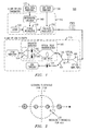
- a 4-ary DP-ASK transmitter 110 of one embodiment of a system 100 according to the invention is illustrated in FIG. 1.
- the light from a laser 120 is first DPSK modulated using one data tributary 135 using a phase modulator 130 which can be a single-waveguide phase modulator, a Mach-Zehnder modulator (MZM) that is biased at null to achieve phase modulation, or the like.
- the MZM can be made from a variety of electro-optic materials, for example, LiNbO 3 , and is preferably biased at its null point to switch the phase of the light signal between 0 and ⁇ .
- a chirp-free MZM is preferred because it produces the DPSK signal with perfect phase values (0 and ⁇ ).
- DPSK encoding is preferably performed using a differential encoder 140 before modulation.
- An intensity modulator 150 then modulates the DPSK signal using a second data tributary 155.
- the intensity modulator 150 is driven to produce an extinction ratio (ER) of about 6 to 9 dB.
- the intensity modulator 150 can be a MZM, an electro-absorption modulator (EAM), or the like.
- a MZM a low ER can be achieved by under-driving the MZM and shifting the bias point away from the quadrature point.
- a low ER can be achieved by shifting the bias point.
- the order of the DPSK and ASK modulation of an optical signal may be reversed while still providing a DP-ASK signal according to the invention.
- the system 100 preferably also includes a receiver 175.
- An erbium-doped fiber amplifier 180 (EDFA) is preferably used in the receiver 175 as an optical pre-amplifier.
- An optical filter 181 is preferably provided after the pre-amplifier 180 to reduce the penalty from amplified-spontaneous-emission (ASE) noise.
- the amplified signal is then preferably separated into two paths 183, 184.
- One path 183 transmits the signal to a DPSK receiver 190.
- the DPSK receiver 190 preferably comprises a one-bit delay interferometer 192, a balanced detector 194, and a differential RF amplifier 196 for detection of the DPSK tributary (i.e., the DPSK modulated portion or component of the signal).
- the one-bit delay interferometer 192 is preferably provided to divide the light on path 183 into two arms and delay one arm by about one bit period. It can be understood by those skilled in the art that the delay provided by the delay interferometer 192 can vary from precisely one bit period while still providing sufficient delay in accordance with the invention. Preferably, the delay provided by the delay interferometer 192 is between about 0.8 and about 1.2 times the bit period.
- the other path 184 transmits the signal to an ASK detector 198 for detection of the ASK tributary portion of the signal.
- FIG. 2 is a plot illustrating the constellation diagram of four symbols of 4-ary DP-ASK modulation.
- the x-axis represents the real part of the optical field
- the y-axis represents the imaginary part of the optical field.
- the DPSK data tributary is recovered by setting the decision threshold at the y-axis to compare the signs (or phases) of adjacent bits, which can be realized by using a delay interferometer 192 and a balanced detector 194 and setting the decision threshold at 0. For example, if two adjacent bits have the same (or opposite) sign, then "1" (or "-1") is determined.
- the ASK data tributary is preferably retrieved by setting the decision threshold at the circle 210 with a radius that is the mean of the larger and smaller amplitude of the symbols.
- An embodiment of the invention has been demonstrated experimentally with an aggregate 20-Gb/s non-return-to-zero (NRZ) 4-ary DP-ASK signal.
- the cw source 120 used was a tunable laser operating at 1550 nm.
- a 10-Gb/s DPSK tributary was modulated on the cw light by a MZM that is biased at null and driven at 2V ⁇ to achieve phase modulation.
- the light was then intensity modulated with ⁇ 8 dB ER to carry a 10-Gb/s ASK tributary. It was found that the ER of the ASK modulation is more preferably about 9.5 dB to achieve equal receiver sensitivity for the two data tributaries.
- optical signal-to-noise (OSNR) requirement at a given BER for a 4-ary DP-ASK was determined to be only about 1dB higher than that for a binary on-off-keying (OOK) format with the same overall data rate.
- OOK binary on-off-keying
- 4ary DP-ASK requires about 4.5 dB less OSNR for a given BER.
- the preferred ER is about 8 dB.
- the low ER was achieved by under-driving MZM at about 0.9V ⁇ , and shifting the bias point away from the quadrature point of the MZM by about 0.05 V ⁇ .
- a commercial chirp-free two-stage integrated MZ modulator was used.
- the bandwidths of the two MZMs were about 10 GHz.
- the total insertion loss of the transmitter was about 5.5 dB.
- an EDFA with about 4.5 dB NF was used as the optical pre-amplifier 180.
- the optical filter 181 after the pre-amplifier 180 had a 3-dB bandwidth of 100-GHz.
- the amplified signal was split into two signals, one entering a DPSK receiver 190 comprising a 100-ps delay interferometer 192, a balanced detector 194, and a differential RF amplifier 196, and the other entering an ASK detector.
- the effective RF bandwidths of the two receivers were about 7 GHz.
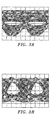
- FIGS. 3a-b show the eye diagrams detected at the DPSK and ASK receivers 190, 198.
- the decision level was fixed at 0.
- FIG. 4 shows the BER performance of both DPSK and ASK vs. the received optical power (before the pre-amplifier).
- a pulse pattern generator was used to produce a data stream that consisted of pseudorandom bit sequences (PRBS) with a pattern length of 2 7 -1, and its inverted copy.
- PRBS pseudorandom bit sequences
- the DPSK modulator 130 was driven by the data and the ASK modulator 150 by the inverted data which was delayed by ⁇ 30 bits to de-correlate the two data streams to the modulators 130, 150. It is understood that inverted/delayed data was used only for the experimental purpose of generating two data tributaries.
- the sensitivity was about 6 dB worse than that of 10-Gb/s binary NRZ (for the experimental embodiment), or about 2 dB worse than the theoretically predicted performance, mainly due to the limited dynamic range of the DPSK receiver 190.
- FIGS. 5a-b show the performance of the 20-Gb/s 4-ary DP-ASK under 425 ps/nm dispersion and under a tight filtering by an arrayed-waveguide-grating (AWG) with 25-GHz channel spacing and ⁇ 20-GHz passband.
- AMG arrayed-waveguide-grating
- the dispersion penalties for the DPSK and ASK tributaries were both less than 1 dB, similar to binary 10-Gb/s NRZ transmission.
- the receiver sensitivities of the DPSK and ASK tributaries were improved by 1 dB and 0.7 dB, respectively.
- the AWG effectively limits the bandwidth of ASE noise and thus improves the receiver sensitivity.
- the experimental results also show less than 1dB penalty when the bandwidth is further reduced to 16 GHz, suggesting that 4-ary DP-ASK may be transmitted at greater than about 100% spectral efficiency.
- the experiment is described in detail in a paper submitted to ECOC'03 by X. Liu, et al., entitled “Quaternary Differential-Phase Amplitude-Shift-Keying For DWDM Transmission,” which is incorporated herein by reference.
- the 4-ary DP-ASK modulation can be based on a return-to-zero (RZ) pulse format.
- RZ 4-ary DP-ASK can provide improved receiver sensitivity as compared to NRZ 4-ary DP-ASK.
- RZ 4-ary DP-ASK can be realized either optically, by using for example, another modulator (not shown) to generate a pulse at each bit slot, or electrically, by using for example, an RZ pulse generator to provide RZ RF data to drive the intensity modulator 150.
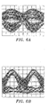
- FIGS. 6a-b show the received electrical eye diagrams of the DPSK data tributary and the ASK data tributary of a 20-Gb/s RZ 4-ary DP-ASK back-to-back transmission with pulse generation done electronically.
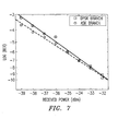
- FIG. 7 is a plot showing the measured BER performance of the DPSK tributary and ASK tributary of the 20-Gb/s RZ 4-ary DP-ASK back-to-back transmission.
- the overall receiver sensitivity of the RZ 4-ary DP-ASK transmission is about 2 dB better than NRZ 4-ary DP-ASK transmission.
- FIG. 8 is a schematic diagram illustrating the use of pre-emphasis through chirped ASK to combat the SPM penalty.
- the chirped ASK modulation can be realized by driving one arm of a dual-drive MZM in such a way that any high-intensity "1" has a phase shift which is smaller than the phase shift of a low-intensity "0".
- post-NPSC post nonlinear phase shift compensation
- One method of post-NPSC which can be used in accordance with the present invention is disclosed in U.S. patent application, Serial No. 10/331,217, entitled “Nonlinear Phase-Shift Compensation Method And Apparatus", which is incorporated herein by reference.
- Detailed descriptions of the post-NPSC method can also be found in X. Liu et al., "Improving Transmission Performance In Differential Phase-Shift-Keyed Systems By Use of Lumped Nonlinear Phase-Shift Compensation", Optics Letters, Vol. 27, pp.
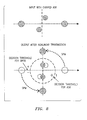
- FIG. 9 is the schematic diagram illustrating the use of post-NPSC to compensate for the differential-phase closure resulting from SPM during nonlinear transmissions.
Abstract
Description
- The present invention relates generally to wavelength division multiplexed (WDM) optical transmission, and more specifically to a system and method for generating multilevel coded optical signals.
- Multilevel amplitude-shift-keying (M-ary ASK) provides a means for increasing the information spectral density or the capacity of a transmission system. M-ary ASK also substantially improves system tolerance to chromatic dispersion and polarization-mode-dispersion (PMD) by lowering the symbol rate for a given bit rate.
- Quaternary (4-ary) ASK modulation formats have been proposed and demonstrated in the prior art. In a 4-ary ASK format, each symbol has four different optical intensities but the same phase. Such a format is discussed in Walklin and Conradi, "Multilevel Signaling For Increasing The Reach of 10 Gb/s Lightwave Systems", Journal of Lightwave Technologies, Vol. 17, pp. 2235-2248 (1999), which is incorporated herein by reference. This format, however, suffers a large power penalty as compared to a conventional binary format with the same overall data rate, which precludes the use of 4-ary ASK for conventional DWDM transmissions. The performance of this format as compared to conventional formats is discussed in detail by Conradi in Chapter 16 of Optical Fiber Telecommunications IVB, Academic Press, which is incorporated herein by reference.
- Differential quadrature phase-shift-keying (DQPSK) is another multilevel modulation format, which offers improved tolerance to dispersion and PMD with good receiver sensitivity. DQPSK, however, requires more complex transmitters and receivers as compared to other formats. In the DQPSK format, each symbol has four equally spaced phases but the same intensity. This format is discussed in R. A. Griffin et al., "Optical Differential Quadrature Phase-Shift Key (oDQPSK) For High Capacity Optical Transmission", Proceedings of OFC 2002 pp. 367-368 (2002), which is incorporated herein by reference.
- The present invention provides a system and method for generating an optical multilevel signal by differential-phase amplitude-shift keying (DP-ASK) modulation in which two sets of data, one modulated using differential-phase-shift-keying (DPSK) and the other modulated using amplitude-shift-keying (ASK), are modulated and transmitted simultaneously yet independently at a single wavelength. Both the intensity and phase of a CW carrier are modulated to provide four possible symbols for a given information bit.
- In one embodiment, a method comprises the step of driving at least two modulators with at least two synchronous data signals having the same data rate to generate an optical signal using differential phase shift keying and amplitude shift keying modulation.
- In another embodiment an optical transmission system is provided comprising an optical 4-ary DP-ASK transmitter including at least two modulators adapted to provide an optical 4-ary DP-ASK modulated signal. The system also includes an optical receiver including a DPSK receiver that includes a delay interferometer and a balanced receiver to detect a DPSK modulated portion of the 4-ary DP-ASK modulated signal. The receiver also includes an optical intensity receiver to detect an ASK modulated portion of the 4-ary DP-ASK modulated signal.
-
- FIG. 1 is a diagram depicting one embodiment of an optical system according to the invention.
- FIG. 2 is a plot illustrating a constellation diagram of 4-ary DP-ASK symbols.
- FIGS. 3a-b are the received electrical eye diagrams of a DPSK portion and an ASK portion of a DP-ASK back-to-back transmission in accordance with an embodiment of the invention.
- FIG. 4 is a plot showing the measured BER performance of a system according to an embodiment of the invention.
- FIGS. 5a-b are plots showing the measured BER performance and the measured signal spectrum of a system according to an embodiment of the invention.
- FIGS. 6a-b are the received electrical eye diagrams of a DPSK portion and an ASK portion of a return-to-zero (RZ) DP-ASK back-to-back transmission in accordance with an embodiment of the invention.
- FIG. 7 is a plot showing the measured BER performance of a system in accordance with an embodiment of the invention.
- FIG. 8 is a schematic diagram illustrating the use of pre-emphasis through chirped ASK to combat differential-phase eye closure penalty resulting from self-phase modulation (SPM) during nonlinear transmissions.
- FIG. 9 is a schematic diagram illustrating the use of post nonlinear phase shift compensation (post-NPSC) to compensate for the differential-phase closure resulting from SPM during nonlinear transmissions.
-
- In preferred embodiments, the present invention provides a system and method for generating optical 4-ary DP-ASK signals for transmission in an optical transmission system using two modulators, one for DPSK modulation and the other for ASK modulation. Such a system allows for the simultaneous yet independent transmission and reception of two data tributaries. Preferably, the two data tributaries have the same data rate and are modulated synchronously such that the bit centers of the two tributaries are aligned in time (to avoid the distortion at the center of ASK bits during the transition between adjacent DPSK bits).
- A 4-ary DP-
ASK transmitter 110 of one embodiment of asystem 100 according to the invention is illustrated in FIG. 1. The light from alaser 120 is first DPSK modulated using onedata tributary 135 using aphase modulator 130 which can be a single-waveguide phase modulator, a Mach-Zehnder modulator (MZM) that is biased at null to achieve phase modulation, or the like. The MZM can be made from a variety of electro-optic materials, for example, LiNbO3, and is preferably biased at its null point to switch the phase of the light signal between 0 and π. A chirp-free MZM is preferred because it produces the DPSK signal with perfect phase values (0 and π). - DPSK encoding is preferably performed using a
differential encoder 140 before modulation. Anintensity modulator 150 then modulates the DPSK signal using asecond data tributary 155. Preferably, theintensity modulator 150 is driven to produce an extinction ratio (ER) of about 6 to 9 dB. Theintensity modulator 150 can be a MZM, an electro-absorption modulator (EAM), or the like. For a MZM, a low ER can be achieved by under-driving the MZM and shifting the bias point away from the quadrature point. For modulation with an EAM, a low ER can be achieved by shifting the bias point. The order of the DPSK and ASK modulation of an optical signal may be reversed while still providing a DP-ASK signal according to the invention. - The
system 100 preferably also includes areceiver 175. An erbium-doped fiber amplifier 180 (EDFA) is preferably used in thereceiver 175 as an optical pre-amplifier. Anoptical filter 181 is preferably provided after the pre-amplifier 180 to reduce the penalty from amplified-spontaneous-emission (ASE) noise. The amplified signal is then preferably separated into twopaths path 183 transmits the signal to aDPSK receiver 190. TheDPSK receiver 190 preferably comprises a one-bit delay interferometer 192, abalanced detector 194, and adifferential RF amplifier 196 for detection of the DPSK tributary (i.e., the DPSK modulated portion or component of the signal). The one-bit delay interferometer 192 is preferably provided to divide the light onpath 183 into two arms and delay one arm by about one bit period. It can be understood by those skilled in the art that the delay provided by thedelay interferometer 192 can vary from precisely one bit period while still providing sufficient delay in accordance with the invention. Preferably, the delay provided by thedelay interferometer 192 is between about 0.8 and about 1.2 times the bit period. - The
other path 184 transmits the signal to anASK detector 198 for detection of the ASK tributary portion of the signal. - FIG. 2 is a plot illustrating the constellation diagram of four symbols of 4-ary DP-ASK modulation. In the diagram, the x-axis represents the real part of the optical field, and the y-axis represents the imaginary part of the optical field. The DPSK data tributary is recovered by setting the decision threshold at the y-axis to compare the signs (or phases) of adjacent bits, which can be realized by using a
delay interferometer 192 and abalanced detector 194 and setting the decision threshold at 0. For example, if two adjacent bits have the same (or opposite) sign, then "1" (or "-1") is determined. The ASK data tributary is preferably retrieved by setting the decision threshold at thecircle 210 with a radius that is the mean of the larger and smaller amplitude of the symbols. - An embodiment of the invention has been demonstrated experimentally with an aggregate 20-Gb/s non-return-to-zero (NRZ) 4-ary DP-ASK signal. The
cw source 120 used was a tunable laser operating at 1550 nm. A 10-Gb/s DPSK tributary was modulated on the cw light by a MZM that is biased at null and driven at 2Vπ to achieve phase modulation. The light was then intensity modulated with ∼8 dB ER to carry a 10-Gb/s ASK tributary. It was found that the ER of the ASK modulation is more preferably about 9.5 dB to achieve equal receiver sensitivity for the two data tributaries. The optical signal-to-noise (OSNR) requirement at a given BER for a 4-ary DP-ASK was determined to be only about 1dB higher than that for a binary on-off-keying (OOK) format with the same overall data rate. Compared with 4-ary ASK with quadratic power levelling, 4ary DP-ASK requires about 4.5 dB less OSNR for a given BER. - Due to the limited dynamic range of the DPSK receiver used in the experiment it was determined that the preferred ER is about 8 dB. The low ER was achieved by under-driving MZM at about 0.9Vπ, and shifting the bias point away from the quadrature point of the MZM by about 0.05 Vπ.
- To simplify the transmitter, a commercial chirp-free two-stage integrated MZ modulator was used. The bandwidths of the two MZMs were about 10 GHz. The total insertion loss of the transmitter was about 5.5 dB.
- At the
receiver 175, an EDFA with about 4.5 dB NF was used as theoptical pre-amplifier 180. Theoptical filter 181 after thepre-amplifier 180 had a 3-dB bandwidth of 100-GHz. The amplified signal was split into two signals, one entering aDPSK receiver 190 comprising a 100-ps delay interferometer 192, abalanced detector 194, and adifferential RF amplifier 196, and the other entering an ASK detector. The effective RF bandwidths of the two receivers were about 7 GHz. - FIGS. 3a-b show the eye diagrams detected at the DPSK and ASK
receivers balanced detector 194, the decision level was fixed at 0. FIG. 4 shows the BER performance of both DPSK and ASK vs. the received optical power (before the pre-amplifier). - A pulse pattern generator was used to produce a data stream that consisted of pseudorandom bit sequences (PRBS) with a pattern length of 27-1, and its inverted copy. The
DPSK modulator 130 was driven by the data and theASK modulator 150 by the inverted data which was delayed by ∼30 bits to de-correlate the two data streams to themodulators - Receiver sensitivity (at BER= 10-9) of ―30.5 dBm was achieved for both DPSK and ASK
receivers DPSK receiver 190. - 4-ary DP-ASK is understood to have a high tolerance to chromatic dispersion and optical filtering. FIGS. 5a-b show the performance of the 20-Gb/s 4-ary DP-ASK under 425 ps/nm dispersion and under a tight filtering by an arrayed-waveguide-grating (AWG) with 25-GHz channel spacing and ∼20-GHz passband. The dispersion penalties for the DPSK and ASK tributaries were both less than 1 dB, similar to binary 10-Gb/s NRZ transmission. With the filtering, the receiver sensitivities of the DPSK and ASK tributaries were improved by 1 dB and 0.7 dB, respectively. The AWG effectively limits the bandwidth of ASE noise and thus improves the receiver sensitivity. The experimental results also show less than 1dB penalty when the bandwidth is further reduced to 16 GHz, suggesting that 4-ary DP-ASK may be transmitted at greater than about 100% spectral efficiency. The experiment is described in detail in a paper submitted to ECOC'03 by X. Liu, et al., entitled "Quaternary Differential-Phase Amplitude-Shift-Keying For DWDM Transmission," which is incorporated herein by reference.
- In another embodiment of the invention the 4-ary DP-ASK modulation can be based on a return-to-zero (RZ) pulse format. RZ 4-ary DP-ASK can provide improved receiver sensitivity as compared to NRZ 4-ary DP-ASK. RZ 4-ary DP-ASK can be realized either optically, by using for example, another modulator (not shown) to generate a pulse at each bit slot, or electrically, by using for example, an RZ pulse generator to provide RZ RF data to drive the
intensity modulator 150. - FIGS. 6a-b show the received electrical eye diagrams of the DPSK data tributary and the ASK data tributary of a 20-Gb/s RZ 4-ary DP-ASK back-to-back transmission with pulse generation done electronically. FIG. 7 is a plot showing the measured BER performance of the DPSK tributary and ASK tributary of the 20-Gb/s RZ 4-ary DP-ASK back-to-back transmission. The overall receiver sensitivity of the RZ 4-ary DP-ASK transmission is about 2 dB better than NRZ 4-ary DP-ASK transmission.
- In another embodiment of the invention using 4-ary DP-ASK modulation in nonlinear transmissions, where self-phase-modulation (SPM) induces different phase shifts for signals with different intensities and causes the differential-phase eye closure which degrades the performance of DPSK tributary, pre-emphasis is used to combat the SPM penalty. FIG. 8 is a schematic diagram illustrating the use of pre-emphasis through chirped ASK to combat the SPM penalty. The chirped ASK modulation can be realized by driving one arm of a dual-drive MZM in such a way that any high-intensity "1" has a phase shift which is smaller than the phase shift of a low-intensity "0". By doing so, after nonlinear transmission over which SPM introduces more phase shift to "1s" than to "0s", the overall phases of "1s" and "0s" are close to those in the ideal case (as shown in Fig. 2) for optimal receiver sensitivity. Since an optimum nonlinear phase shift is about 1 radian in nonlinear DPSK transmission, a chirped ASK modulation with an ER between about 5 dB and 9 dB is preferred.
- In another embodiment of the invention using 4-ary DP-ASK modulation in nonlinear transmissions, post nonlinear phase shift compensation (post-NPSC) is used to compensate for the SPM-induced differential-phase eye closure. One method of post-NPSC which can be used in accordance with the present invention is disclosed in U.S. patent application, Serial No. 10/331,217, entitled "Nonlinear Phase-Shift Compensation Method And Apparatus", which is incorporated herein by reference. Detailed descriptions of the post-NPSC method can also be found in X. Liu et al., "Improving Transmission Performance In Differential Phase-Shift-Keyed Systems By Use of Lumped Nonlinear Phase-Shift Compensation", Optics Letters, Vol. 27, pp. 1616-1618, (2002), and in C. Xu and X. Liu, "Postnonlinearity Compensation With Data-Driven Phase Modulators In Phase-Shift Keying Transmission", Optics Letters, Vol. 27, pp. 1619-1621 (2002), which are also incorporated herein by reference. FIG. 9 is the schematic diagram illustrating the use of post-NPSC to compensate for the differential-phase closure resulting from SPM during nonlinear transmissions.
- Although the present invention has been described in accordance with the embodiments shown, one skilled in the art will readily recognize that there could be variations to the embodiments, and that those variations would be within the spirit and scope of the present invention as defined by the appended claims.
Claims (10)
- A communication method for multilevel coded optical signal transmission comprising the step of:driving at least two modulators with at least two synchronous data signals having the same data rate to generate an optical signal using differential phase shift keying and amplitude shift keying modulation.
- The method of claim 1 further comprising providing post nonlinear-phase-shift compensation to substantially reduce the penalty from self-phase-modulation during nonlinear transmission.
- The method of claim 1 wherein the amplitude shift keying modulation generates chirp-free optical signals.
- The method of claim 1 wherein the amplitude shift keying modulation generates chirped optical signals.
- The method of claim 1 wherein the amplitude shift keying modulation has an extinction ratio of between about 5 dB and about 10 dB.
- A transmitter apparatus for generating differential phase amplitude shift keyed optical signals comprising:a modulator means, including at least two modulators driven by synchronous data signals having the same data rate, adapted to generate an optical signal using differential phase shift keying and amplitude shift keying modulation.
- The apparatus of claim 6 further comprising a pulse generator operatively coupled to the modulator means to allow for generation of RZ optical signals.
- An optical transmission system comprising:wherein the first and second data signals are synchronous and have the same data rate, and wherein the first and second modulators are adapted to generate a multilevel coded optical signal using differential phase shift keying and amplitude shift keying modulation.a first modulator adapted to receive a first data signal;a second modulator coupled to the first modulator and adapted to receive a second data signal;
- The system of claim 8 further comprising a receiver including a balanced detector for detection of a differential phase shift keyed portion of the optical signal.
- An optical transmission system comprising:an optical 4-ary DP-ASK transmitter including at least two modulators adapted to provide an optical 4-ary DP-ASK modulated signal; andan optical receiver including:a DPSK receiver including a delay interferometer and a balanced receiver to detect a DPSK modulated portion of the 4-ary DP-ASK modulated signal; andan optical intensity receiver to detect an ASK modulated portion of the 4-ary DP-ASK modulated signal.
Applications Claiming Priority (2)
| Application Number | Priority Date | Filing Date | Title |
|---|---|---|---|
| US10/673,933 US20050069330A1 (en) | 2003-09-29 | 2003-09-29 | System and method for optical transmission |
| US673933 | 2003-09-29 |
Publications (2)
| Publication Number | Publication Date |
|---|---|
| EP1519499A1 true EP1519499A1 (en) | 2005-03-30 |
| EP1519499B1 EP1519499B1 (en) | 2006-12-13 |
Family
ID=34194897
Family Applications (1)
| Application Number | Title | Priority Date | Filing Date |
|---|---|---|---|
| EP04255617A Expired - Fee Related EP1519499B1 (en) | 2003-09-29 | 2004-09-16 | System and method for generating multilevel coded optical signals |
Country Status (5)
| Country | Link |
|---|---|
| US (1) | US20050069330A1 (en) |
| EP (1) | EP1519499B1 (en) |
| JP (1) | JP2005110256A (en) |
| CN (1) | CN1604514A (en) |
| DE (1) | DE602004003647T2 (en) |
Cited By (12)
| Publication number | Priority date | Publication date | Assignee | Title |
|---|---|---|---|---|
| EP1742389A1 (en) * | 2005-07-06 | 2007-01-10 | National Institute of Information and Communications Technology Incorporated Administrative Agency | Data transmisson method and a system thereof |
| WO2007037919A1 (en) * | 2005-09-25 | 2007-04-05 | Lucent Technologies Inc. | Multilevel amplitude and phase encoded signal generation |
| WO2007127208A2 (en) * | 2006-04-26 | 2007-11-08 | Mintera Corporation | Partial dpsk (pdpsk) transmission systems |
| WO2008010935A2 (en) * | 2006-07-20 | 2008-01-24 | Lucent Technologies Inc. | Method and apparatus for the generation and detection of optical differential varied-multilevel phase-shift keying with pulse amplitude modulation (odvmpsk/pam) signals |
| EP1912355A1 (en) * | 2006-10-13 | 2008-04-16 | Alcatel Lucent | Method and receiver to increase the spectral efficiency of DPSK modulation format |
| EP2230782A1 (en) | 2009-03-19 | 2010-09-22 | Alcatel Lucent | Monitoring of non-linear distortions in a fiber-optic transmission system |
| CN102413388A (en) * | 2011-11-18 | 2012-04-11 | 电子科技大学 | Optical fiber wireless RoF passive optical network realizing method based on optical code division multiplexing |
| US8208816B2 (en) | 2007-04-20 | 2012-06-26 | Finisar Corporation | Method and apparatus for dispersion mitigation in optical links |
| US8320777B2 (en) | 2008-05-08 | 2012-11-27 | Finisar Corporation | Temperature controlled interferometer for phase demodulation |
| US8401383B2 (en) | 2009-05-13 | 2013-03-19 | Adva Optical Networking Se | Data transmission method and network for transmitting a digital optical signal over optical transmission links and networks |
| US9325425B2 (en) | 2008-02-24 | 2016-04-26 | Finisar Corporation | Method and apparatus for demodulating and regenerating phase modulated optical signals |
| EP2506477A3 (en) * | 2011-04-01 | 2016-11-09 | Infinera Corporation | Multiplexer and modulation arrangements for multi-carrier optical modems |
Families Citing this family (31)
| Publication number | Priority date | Publication date | Assignee | Title |
|---|---|---|---|---|
| KR100584433B1 (en) * | 2003-11-25 | 2006-05-26 | 삼성전자주식회사 | Differential-phase-shift-keying optical transmission system |
| EP1536579B1 (en) * | 2003-11-25 | 2006-07-19 | Alcatel | Modified DPSK optical transmission system |
| JP3829198B2 (en) * | 2003-12-01 | 2006-10-04 | 独立行政法人情報通信研究機構 | Optical transmission method and system |
| GB0417687D0 (en) * | 2004-08-09 | 2004-09-08 | Azea Networks Ltd | An optical receiver and an optical transmission system incorporating the same |
| DE102005041368A1 (en) * | 2005-08-31 | 2007-03-01 | Siemens Ag | Demodulation method for optical differential phase shift keying (DPSK) binary signals, involves demodulating phase-modulated and amplitude-modulated optical DPSK binary signal and evaluating phase and amplitude data of demodulated signal |
| JP4437985B2 (en) | 2005-08-31 | 2010-03-24 | 富士通株式会社 | Multi-level differential optical signal receiver |
| JP4562657B2 (en) * | 2006-01-12 | 2010-10-13 | 日本電信電話株式会社 | Demodulator circuit |
| WO2008094274A1 (en) * | 2006-04-28 | 2008-08-07 | Cornell Research Foundation, Inc . | Methods and systems for compensation of self-phase modulation in fiber-based amplification systems |
| US9312964B2 (en) * | 2006-09-22 | 2016-04-12 | Alcatel Lucent | Reconstruction and restoration of an optical signal field |
| FR2917932A1 (en) * | 2007-06-19 | 2008-12-26 | Thomson Licensing Sas | METHOD FOR DETECTING SATELLITE TRANSMISSION CHANNELS AND RECEPTION DEVICE USING THE METHOD. |
| US8463141B2 (en) * | 2007-09-14 | 2013-06-11 | Alcatel Lucent | Reconstruction and restoration of two polarization components of an optical signal field |
| IL187836A0 (en) * | 2007-12-03 | 2008-03-20 | Eci Telecom Ltd | Technique for generating multilevel coded optical signals |
| JPWO2009113355A1 (en) | 2008-03-10 | 2011-07-21 | 住友電気工業株式会社 | Optical communication system |
| JP5334718B2 (en) * | 2009-07-10 | 2013-11-06 | 日本電信電話株式会社 | Optical code division multiplexing transmission circuit and optical code division multiplexing reception circuit |
| JP5334747B2 (en) * | 2009-08-21 | 2013-11-06 | 日本電信電話株式会社 | Optical code division multiplexing transmission system and optical code division multiplexing transmission method |
| EP2548318B1 (en) * | 2010-03-19 | 2013-12-18 | Telefonaktiebolaget L M Ericsson (PUBL) | An optical communications system |
| US8750722B2 (en) * | 2010-12-24 | 2014-06-10 | Infinera Corporation | Upgradable WDM system |
| US20120321324A1 (en) * | 2011-06-17 | 2012-12-20 | Nec Laboratories America, Inc. | Architecture of 4-ASK Transmitter |
| US8718160B2 (en) | 2011-09-16 | 2014-05-06 | Beijing University Of Posts And Telecommunications | Multi-carrrier optical communication method and system based on DAPSK |
| CN102427387A (en) * | 2011-12-02 | 2012-04-25 | 北京邮电大学 | Optical communication method and system |
| CN102325122B (en) * | 2011-10-20 | 2013-09-25 | 电子科技大学 | Two-way passive optical network system based on OFDM-ROF (Orthogonal Frequency Division Multiplexing-Radio Over Fiber) |
| EP2688232B1 (en) * | 2012-07-19 | 2017-06-14 | Alcatel Lucent | Optical transmitter for transmitting a multilevel amplitude-shift-keying modulated signal |
| JP6015291B2 (en) * | 2012-09-24 | 2016-10-26 | 沖電気工業株式会社 | Optical signal quality evaluation apparatus and optical signal quality evaluation method |
| JP5937982B2 (en) * | 2013-03-05 | 2016-06-22 | 日本電信電話株式会社 | Optical transmission system using tunable light source |
| US9838239B2 (en) * | 2015-01-22 | 2017-12-05 | Futurewei Technologies, Inc. | Digital generation of multi-level phase shifting with a Mach-Zehnder modulator (MZM) |
| US9762332B1 (en) * | 2016-03-07 | 2017-09-12 | Verizon Patent And Licensing Inc. | High capacity transmission system with full nonlinear penalty cancellation |
| WO2019159891A1 (en) * | 2018-02-16 | 2019-08-22 | 日本電気株式会社 | Light transmitter, light receiver, and optical communication method |
| CN109039462B (en) * | 2018-07-19 | 2020-04-03 | 中国科学院西安光学精密机械研究所 | Multi-modulation format compatible high-speed laser signal phase-lock-free receiving system and method |
| KR102229864B1 (en) * | 2020-01-22 | 2021-03-18 | 연세대학교 산학협력단 | Free space optical transmitter/receiver based on polarization position and differential phase shift keying and transmitting/receiving method thereof |
| CN115276809A (en) * | 2021-04-30 | 2022-11-01 | 华为技术有限公司 | Optical signal acquisition method and related equipment |
| CN113992273A (en) * | 2021-12-27 | 2022-01-28 | 中国工程物理研究院激光聚变研究中心 | High signal-to-noise ratio spectral output system |
Citations (2)
| Publication number | Priority date | Publication date | Assignee | Title |
|---|---|---|---|---|
| US20030058504A1 (en) * | 2000-09-26 | 2003-03-27 | Cho Pak Shing | Method and system for mitigating nonlinear transmission impairments in fiber-optic communications systems |
| US20030147646A1 (en) * | 2002-02-04 | 2003-08-07 | Mario Zitelli | Combined phase and intensity modulation in optical communication systems |
Family Cites Families (4)
| Publication number | Priority date | Publication date | Assignee | Title |
|---|---|---|---|---|
| FR2781322B1 (en) * | 1998-07-20 | 2000-09-08 | Alsthom Cge Alcatel | OPTICAL DATA TRANSMISSION DEVICE |
| US6626589B1 (en) * | 1999-12-29 | 2003-09-30 | Nortel Networks Limited | Optical packet switching |
| GB2366106B (en) * | 2000-08-19 | 2004-06-23 | Marconi Caswell Ltd | Multi-level optical signal generation |
| US20030063698A1 (en) * | 2001-09-28 | 2003-04-03 | Andrew Bonthron | Optical synchronous coding system |
-
2003
- 2003-09-29 US US10/673,933 patent/US20050069330A1/en not_active Abandoned
-
2004
- 2004-09-16 EP EP04255617A patent/EP1519499B1/en not_active Expired - Fee Related
- 2004-09-16 DE DE602004003647T patent/DE602004003647T2/en active Active
- 2004-09-24 CN CN200410011748.8A patent/CN1604514A/en active Pending
- 2004-09-27 JP JP2004278822A patent/JP2005110256A/en not_active Withdrawn
Patent Citations (2)
| Publication number | Priority date | Publication date | Assignee | Title |
|---|---|---|---|---|
| US20030058504A1 (en) * | 2000-09-26 | 2003-03-27 | Cho Pak Shing | Method and system for mitigating nonlinear transmission impairments in fiber-optic communications systems |
| US20030147646A1 (en) * | 2002-02-04 | 2003-08-07 | Mario Zitelli | Combined phase and intensity modulation in optical communication systems |
Non-Patent Citations (2)
| Title |
|---|
| NAN CHI ET AL: "Transmission performance of all-optically labelled packets using ASK/DPSK orthogonal modulation", LEOS 2002. 15TH. ANNUAL MEETING OF THE IEEE LASERS & ELECTRO-OPTICS SOCIETY. GLASCOW, SCOTLAND, NOV. 11 - 12, 2002, ANNUAL MEETING OF THE IEEE LASERS AND ELECTRO-OPTICS SOCIETY, NEW YORK, NY : IEEE, US, vol. VOL. 1 OF 2, 11 November 2002 (2002-11-11), pages 51 - 52, XP010620407, ISBN: 0-7803-7500-9 * |
| OHM M ET AL: "Quaternary optical ASK-DPSK and receivers with direct detection", IEEE PHOTONICS TECHNOLOGY LETTERS, IEEE INC. NEW YORK, US, vol. 15, no. 1, January 2003 (2003-01-01), pages 159 - 161, XP002967126, ISSN: 1041-1135 * |
Cited By (19)
| Publication number | Priority date | Publication date | Assignee | Title |
|---|---|---|---|---|
| EP1742389A1 (en) * | 2005-07-06 | 2007-01-10 | National Institute of Information and Communications Technology Incorporated Administrative Agency | Data transmisson method and a system thereof |
| WO2007037919A1 (en) * | 2005-09-25 | 2007-04-05 | Lucent Technologies Inc. | Multilevel amplitude and phase encoded signal generation |
| US7949261B2 (en) | 2006-04-26 | 2011-05-24 | Mintera Corporation | Partial DPSK (PDPSK) transmission systems |
| WO2007127208A2 (en) * | 2006-04-26 | 2007-11-08 | Mintera Corporation | Partial dpsk (pdpsk) transmission systems |
| WO2007127208A3 (en) * | 2006-04-26 | 2008-02-07 | Mintera Corp | Partial dpsk (pdpsk) transmission systems |
| WO2008010935A2 (en) * | 2006-07-20 | 2008-01-24 | Lucent Technologies Inc. | Method and apparatus for the generation and detection of optical differential varied-multilevel phase-shift keying with pulse amplitude modulation (odvmpsk/pam) signals |
| WO2008010935A3 (en) * | 2006-07-20 | 2008-06-05 | Lucent Technologies Inc | Method and apparatus for the generation and detection of optical differential varied-multilevel phase-shift keying with pulse amplitude modulation (odvmpsk/pam) signals |
| KR101031410B1 (en) * | 2006-07-20 | 2011-04-26 | 알카텔-루센트 유에스에이 인코포레이티드 | Method and apparatus for the generation and detection of optical differential varied-multilevel phase-shift keying with pulse amplitude modulation odvmpsk/pam signals |
| EP1912355A1 (en) * | 2006-10-13 | 2008-04-16 | Alcatel Lucent | Method and receiver to increase the spectral efficiency of DPSK modulation format |
| WO2008043597A1 (en) * | 2006-10-13 | 2008-04-17 | Alcatel Lucent | Method and receiver to increase the spectral efficiency of dpsk modulation format |
| US8208816B2 (en) | 2007-04-20 | 2012-06-26 | Finisar Corporation | Method and apparatus for dispersion mitigation in optical links |
| US9325425B2 (en) | 2008-02-24 | 2016-04-26 | Finisar Corporation | Method and apparatus for demodulating and regenerating phase modulated optical signals |
| US8320777B2 (en) | 2008-05-08 | 2012-11-27 | Finisar Corporation | Temperature controlled interferometer for phase demodulation |
| EP2230782A1 (en) | 2009-03-19 | 2010-09-22 | Alcatel Lucent | Monitoring of non-linear distortions in a fiber-optic transmission system |
| US8401383B2 (en) | 2009-05-13 | 2013-03-19 | Adva Optical Networking Se | Data transmission method and network for transmitting a digital optical signal over optical transmission links and networks |
| EP2251999B1 (en) * | 2009-05-13 | 2013-08-28 | ADVA Optical Networking SE | Data transmission method and network for transmitting a digital optical signal over optical transmission links and networks |
| EP2506477A3 (en) * | 2011-04-01 | 2016-11-09 | Infinera Corporation | Multiplexer and modulation arrangements for multi-carrier optical modems |
| CN102413388A (en) * | 2011-11-18 | 2012-04-11 | 电子科技大学 | Optical fiber wireless RoF passive optical network realizing method based on optical code division multiplexing |
| CN102413388B (en) * | 2011-11-18 | 2014-04-23 | 电子科技大学 | Optical fiber wireless RoF passive optical network realizing method based on optical code division multiplexing |
Also Published As
| Publication number | Publication date |
|---|---|
| EP1519499B1 (en) | 2006-12-13 |
| CN1604514A (en) | 2005-04-06 |
| DE602004003647D1 (en) | 2007-01-25 |
| US20050069330A1 (en) | 2005-03-31 |
| DE602004003647T2 (en) | 2007-10-18 |
| JP2005110256A (en) | 2005-04-21 |
Similar Documents
| Publication | Publication Date | Title |
|---|---|---|
| EP1519499B1 (en) | System and method for generating multilevel coded optical signals | |
| JP4558271B2 (en) | Optical communication improvements or improvements related to optical communications | |
| Wree et al. | High spectral efficiency 1.6-b/s/Hz transmission (8 x 40 Gb/s with a 25-GHz grid) over 200-km SSMF using RZ-DQPSK and polarization multiplexing | |
| US7340168B2 (en) | System and method for optically labeled packet transmission | |
| Wree et al. | RZ-DQPSK format with high spectral efficiency and high robustness towards fiber nonlinearities | |
| US7398022B2 (en) | Optical return-to-zero phase-shift keying with improved transmitters | |
| US8837947B2 (en) | Apparatus for pseudo-return-to-zero modulation | |
| US20090136241A1 (en) | Optical msk data format | |
| EP1612972A1 (en) | Method and apparatus for generating CRZ-DPSK optical signals | |
| US7277647B2 (en) | System and method of optical transmission | |
| Tokle et al. | 6500 km transmission of RZ-DQPSK WDM signals | |
| EP1617576B1 (en) | Bandwidth limited frequency shift keying modulation format | |
| Liu et al. | Transmission of an ASK-labeled RZ-DPSK signal and label erasure using a saturated SOA | |
| US7925169B2 (en) | Photonic encoder | |
| Wei et al. | 40 Gb/s duobinary and modified duobinary transmitter based on an optical delay interferometer | |
| Pradhan et al. | DP-QPSK based 400 Gbps/channel fiber optic DWDM system | |
| Tipsuwannakul et al. | Transmission of 240 Gb/s PM-RZ-D8PSK over 320 km in 10 Gb/s NRZ-OOK WDM System | |
| Gnauck | Advanced amplitude-and phase coded formats for 40-Gb/s fiber transmission | |
| Liu et al. | Optical technologies and techniques for high bit rate fiber transmission | |
| Shao et al. | DRZ, DQPSK, and PoISK orthogonal modulations for 100Gbit/s transmission system applications | |
| Chi et al. | Transmission properties of a 40 Gb/s signal in FSK modulation format | |
| Liu et al. | Return-to-zero quaternary differential-phase amplitude-shift-keying for long-haul transmission | |
| Ibrahim | Study of Multilevel Modulation Formats for High Speed Digital Optical Communication Systems | |
| Ghuri et al. | Comparative Analysis of different Coding Formats for 40 Gb/s System with Various Dispersion Compensation Techniques | |
| Rosenkranz et al. | Modeling and performance evaluation of improved data formats for optical communications |
Legal Events
| Date | Code | Title | Description |
|---|---|---|---|
| PUAI | Public reference made under article 153(3) epc to a published international application that has entered the european phase |
Free format text: ORIGINAL CODE: 0009012 |
|
| 17P | Request for examination filed |
Effective date: 20040927 |
|
| AK | Designated contracting states |
Kind code of ref document: A1 Designated state(s): AT BE BG CH CY CZ DE DK EE ES FI FR GB GR HU IE IT LI LU MC NL PL PT RO SE SI SK TR |
|
| AX | Request for extension of the european patent |
Extension state: AL HR LT LV MK |
|
| 17Q | First examination report despatched |
Effective date: 20050418 |
|
| AKX | Designation fees paid |
Designated state(s): DE FR GB |
|
| GRAP | Despatch of communication of intention to grant a patent |
Free format text: ORIGINAL CODE: EPIDOSNIGR1 |
|
| GRAS | Grant fee paid |
Free format text: ORIGINAL CODE: EPIDOSNIGR3 |
|
| GRAA | (expected) grant |
Free format text: ORIGINAL CODE: 0009210 |
|
| AK | Designated contracting states |
Kind code of ref document: B1 Designated state(s): DE FR GB |
|
| REG | Reference to a national code |
Ref country code: GB Ref legal event code: FG4D |
|
| RIN1 | Information on inventor provided before grant (corrected) |
Inventor name: XING, WEI Inventor name: XIANG, LIU Inventor name: YUAN HUA KAO |
|
| REF | Corresponds to: |
Ref document number: 602004003647 Country of ref document: DE Date of ref document: 20070125 Kind code of ref document: P |
|
| ET | Fr: translation filed | ||
| PLBE | No opposition filed within time limit |
Free format text: ORIGINAL CODE: 0009261 |
|
| STAA | Information on the status of an ep patent application or granted ep patent |
Free format text: STATUS: NO OPPOSITION FILED WITHIN TIME LIMIT |
|
| 26N | No opposition filed |
Effective date: 20070914 |
|
| REG | Reference to a national code |
Ref country code: GB Ref legal event code: 732E Free format text: REGISTERED BETWEEN 20131031 AND 20131106 |
|
| REG | Reference to a national code |
Ref country code: FR Ref legal event code: CD Owner name: ALCATEL-LUCENT USA INC. Effective date: 20131122 |
|
| REG | Reference to a national code |
Ref country code: FR Ref legal event code: GC Effective date: 20140410 |
|
| REG | Reference to a national code |
Ref country code: FR Ref legal event code: RG Effective date: 20141015 |
|
| REG | Reference to a national code |
Ref country code: FR Ref legal event code: PLFP Year of fee payment: 12 |
|
| REG | Reference to a national code |
Ref country code: FR Ref legal event code: PLFP Year of fee payment: 13 |
|
| REG | Reference to a national code |
Ref country code: FR Ref legal event code: PLFP Year of fee payment: 14 |
|
| PGFP | Annual fee paid to national office [announced via postgrant information from national office to epo] |
Ref country code: GB Payment date: 20170921 Year of fee payment: 14 Ref country code: DE Payment date: 20170928 Year of fee payment: 14 Ref country code: FR Payment date: 20170928 Year of fee payment: 14 |
|
| REG | Reference to a national code |
Ref country code: GB Ref legal event code: 732E Free format text: REGISTERED BETWEEN 20190131 AND 20190206 |
|
| REG | Reference to a national code |
Ref country code: DE Ref legal event code: R119 Ref document number: 602004003647 Country of ref document: DE |
|
| REG | Reference to a national code |
Ref country code: DE Ref legal event code: R081 Ref document number: 602004003647 Country of ref document: DE Owner name: PROVENANCE ASSET GROUP LLC, PITTSFORD, US Free format text: FORMER OWNER: LUCENT TECHNOLOGIES INC., MURRAY HILL, N.J., US |
|
| REG | Reference to a national code |
Ref country code: DE Ref legal event code: R081 Ref document number: 602004003647 Country of ref document: DE Owner name: PROVENANCE ASSET GROUP LLC, PITTSFORD, US Free format text: FORMER OWNER: ALCATEL-LUCENT USA INC. (N. D. GES. D. STAATES DELAWARE), MURRAY HILL, N.J., US Ref country code: DE Ref legal event code: R081 Ref document number: 602004003647 Country of ref document: DE Owner name: PROVENANCE ASSET GROUP LLC, PITTSFORD, US Free format text: FORMER OWNER: NOKIA OF AMERICA CORP. (N. D. GES. D. STAATES DELAWARE), MURRAY HILL, NJ, US |
|
| GBPC | Gb: european patent ceased through non-payment of renewal fee |
Effective date: 20180916 |
|
| PG25 | Lapsed in a contracting state [announced via postgrant information from national office to epo] |
Ref country code: DE Free format text: LAPSE BECAUSE OF NON-PAYMENT OF DUE FEES Effective date: 20190402 |
|
| PG25 | Lapsed in a contracting state [announced via postgrant information from national office to epo] |
Ref country code: FR Free format text: LAPSE BECAUSE OF NON-PAYMENT OF DUE FEES Effective date: 20180930 |
|
| PG25 | Lapsed in a contracting state [announced via postgrant information from national office to epo] |
Ref country code: GB Free format text: LAPSE BECAUSE OF NON-PAYMENT OF DUE FEES Effective date: 20180916 |