EP1520571A2 - Noise and light monitor apparatus - Google Patents
Noise and light monitor apparatus Download PDFInfo
- Publication number
- EP1520571A2 EP1520571A2 EP04078246A EP04078246A EP1520571A2 EP 1520571 A2 EP1520571 A2 EP 1520571A2 EP 04078246 A EP04078246 A EP 04078246A EP 04078246 A EP04078246 A EP 04078246A EP 1520571 A2 EP1520571 A2 EP 1520571A2
- Authority
- EP
- European Patent Office
- Prior art keywords
- panel
- patient
- side guard
- support
- door panel
- Prior art date
- Legal status (The legal status is an assumption and is not a legal conclusion. Google has not performed a legal analysis and makes no representation as to the accuracy of the status listed.)
- Withdrawn
Links
- 238000002955 isolation Methods 0.000 claims description 34
- 230000007613 environmental effect Effects 0.000 claims description 5
- 238000012544 monitoring process Methods 0.000 claims description 2
- 239000012530 fluid Substances 0.000 claims 1
- 230000003287 optical effect Effects 0.000 description 11
- 238000011161 development Methods 0.000 description 4
- 238000010586 diagram Methods 0.000 description 4
- 239000000523 sample Substances 0.000 description 4
- 230000007704 transition Effects 0.000 description 4
- 230000003750 conditioning effect Effects 0.000 description 3
- NJPPVKZQTLUDBO-UHFFFAOYSA-N novaluron Chemical compound C1=C(Cl)C(OC(F)(F)C(OC(F)(F)F)F)=CC=C1NC(=O)NC(=O)C1=C(F)C=CC=C1F NJPPVKZQTLUDBO-UHFFFAOYSA-N 0.000 description 3
- 230000002028 premature Effects 0.000 description 3
- 238000012935 Averaging Methods 0.000 description 2
- 230000000712 assembly Effects 0.000 description 2
- 238000000429 assembly Methods 0.000 description 2
- 238000006243 chemical reaction Methods 0.000 description 2
- 230000000994 depressogenic effect Effects 0.000 description 2
- 230000001681 protective effect Effects 0.000 description 2
- 230000035939 shock Effects 0.000 description 2
- 238000010792 warming Methods 0.000 description 2
- 235000004443 Ricinus communis Nutrition 0.000 description 1
- 240000000528 Ricinus communis Species 0.000 description 1
- 230000003213 activating effect Effects 0.000 description 1
- 230000008878 coupling Effects 0.000 description 1
- 238000010168 coupling process Methods 0.000 description 1
- 238000005859 coupling reaction Methods 0.000 description 1
- 238000013480 data collection Methods 0.000 description 1
- 238000012986 modification Methods 0.000 description 1
- 230000004048 modification Effects 0.000 description 1
- 238000001126 phototherapy Methods 0.000 description 1
- 238000012545 processing Methods 0.000 description 1
- 239000007787 solid Substances 0.000 description 1
- XLYOFNOQVPJJNP-UHFFFAOYSA-N water Substances O XLYOFNOQVPJJNP-UHFFFAOYSA-N 0.000 description 1
Images


Classifications
-
- A—HUMAN NECESSITIES
- A61—MEDICAL OR VETERINARY SCIENCE; HYGIENE
- A61F—FILTERS IMPLANTABLE INTO BLOOD VESSELS; PROSTHESES; DEVICES PROVIDING PATENCY TO, OR PREVENTING COLLAPSING OF, TUBULAR STRUCTURES OF THE BODY, e.g. STENTS; ORTHOPAEDIC, NURSING OR CONTRACEPTIVE DEVICES; FOMENTATION; TREATMENT OR PROTECTION OF EYES OR EARS; BANDAGES, DRESSINGS OR ABSORBENT PADS; FIRST-AID KITS
- A61F7/00—Heating or cooling appliances for medical or therapeutic treatment of the human body
-
- A—HUMAN NECESSITIES
- A61—MEDICAL OR VETERINARY SCIENCE; HYGIENE
- A61G—TRANSPORT, PERSONAL CONVEYANCES, OR ACCOMMODATION SPECIALLY ADAPTED FOR PATIENTS OR DISABLED PERSONS; OPERATING TABLES OR CHAIRS; CHAIRS FOR DENTISTRY; FUNERAL DEVICES
- A61G11/00—Baby-incubators; Couveuses
-
- F—MECHANICAL ENGINEERING; LIGHTING; HEATING; WEAPONS; BLASTING
- F24—HEATING; RANGES; VENTILATING
- F24F—AIR-CONDITIONING; AIR-HUMIDIFICATION; VENTILATION; USE OF AIR CURRENTS FOR SCREENING
- F24F11/00—Control or safety arrangements
- F24F11/30—Control or safety arrangements for purposes related to the operation of the system, e.g. for safety or monitoring
- F24F11/32—Responding to malfunctions or emergencies
-
- F—MECHANICAL ENGINEERING; LIGHTING; HEATING; WEAPONS; BLASTING
- F24—HEATING; RANGES; VENTILATING
- F24F—AIR-CONDITIONING; AIR-HUMIDIFICATION; VENTILATION; USE OF AIR CURRENTS FOR SCREENING
- F24F9/00—Use of air currents for screening, e.g. air curtains
-
- G—PHYSICS
- G05—CONTROLLING; REGULATING
- G05D—SYSTEMS FOR CONTROLLING OR REGULATING NON-ELECTRIC VARIABLES
- G05D23/00—Control of temperature
- G05D23/19—Control of temperature characterised by the use of electric means
- G05D23/1902—Control of temperature characterised by the use of electric means characterised by the use of a variable reference value
-
- G—PHYSICS
- G05—CONTROLLING; REGULATING
- G05D—SYSTEMS FOR CONTROLLING OR REGULATING NON-ELECTRIC VARIABLES
- G05D23/00—Control of temperature
- G05D23/19—Control of temperature characterised by the use of electric means
- G05D23/1917—Control of temperature characterised by the use of electric means using digital means
-
- G—PHYSICS
- G05—CONTROLLING; REGULATING
- G05D—SYSTEMS FOR CONTROLLING OR REGULATING NON-ELECTRIC VARIABLES
- G05D23/00—Control of temperature
- G05D23/19—Control of temperature characterised by the use of electric means
- G05D23/1927—Control of temperature characterised by the use of electric means using a plurality of sensors
- G05D23/193—Control of temperature characterised by the use of electric means using a plurality of sensors sensing the temperaure in different places in thermal relationship with one or more spaces
- G05D23/1931—Control of temperature characterised by the use of electric means using a plurality of sensors sensing the temperaure in different places in thermal relationship with one or more spaces to control the temperature of one space
-
- G—PHYSICS
- G05—CONTROLLING; REGULATING
- G05D—SYSTEMS FOR CONTROLLING OR REGULATING NON-ELECTRIC VARIABLES
- G05D27/00—Simultaneous control of variables covered by two or more of main groups G05D1/00 - G05D25/00
- G05D27/02—Simultaneous control of variables covered by two or more of main groups G05D1/00 - G05D25/00 characterised by the use of electric means
-
- G—PHYSICS
- G16—INFORMATION AND COMMUNICATION TECHNOLOGY [ICT] SPECIALLY ADAPTED FOR SPECIFIC APPLICATION FIELDS
- G16H—HEALTHCARE INFORMATICS, i.e. INFORMATION AND COMMUNICATION TECHNOLOGY [ICT] SPECIALLY ADAPTED FOR THE HANDLING OR PROCESSING OF MEDICAL OR HEALTHCARE DATA
- G16H40/00—ICT specially adapted for the management or administration of healthcare resources or facilities; ICT specially adapted for the management or operation of medical equipment or devices
- G16H40/60—ICT specially adapted for the management or administration of healthcare resources or facilities; ICT specially adapted for the management or operation of medical equipment or devices for the operation of medical equipment or devices
- G16H40/63—ICT specially adapted for the management or administration of healthcare resources or facilities; ICT specially adapted for the management or operation of medical equipment or devices for the operation of medical equipment or devices for local operation
-
- G—PHYSICS
- G16—INFORMATION AND COMMUNICATION TECHNOLOGY [ICT] SPECIALLY ADAPTED FOR SPECIFIC APPLICATION FIELDS
- G16H—HEALTHCARE INFORMATICS, i.e. INFORMATION AND COMMUNICATION TECHNOLOGY [ICT] SPECIALLY ADAPTED FOR THE HANDLING OR PROCESSING OF MEDICAL OR HEALTHCARE DATA
- G16H40/00—ICT specially adapted for the management or administration of healthcare resources or facilities; ICT specially adapted for the management or operation of medical equipment or devices
- G16H40/60—ICT specially adapted for the management or administration of healthcare resources or facilities; ICT specially adapted for the management or operation of medical equipment or devices for the operation of medical equipment or devices
- G16H40/67—ICT specially adapted for the management or administration of healthcare resources or facilities; ICT specially adapted for the management or operation of medical equipment or devices for the operation of medical equipment or devices for remote operation
-
- A—HUMAN NECESSITIES
- A61—MEDICAL OR VETERINARY SCIENCE; HYGIENE
- A61B—DIAGNOSIS; SURGERY; IDENTIFICATION
- A61B17/00—Surgical instruments, devices or methods, e.g. tourniquets
- A61B2017/00017—Electrical control of surgical instruments
- A61B2017/00115—Electrical control of surgical instruments with audible or visual output
- A61B2017/00119—Electrical control of surgical instruments with audible or visual output alarm; indicating an abnormal situation
-
- A—HUMAN NECESSITIES
- A61—MEDICAL OR VETERINARY SCIENCE; HYGIENE
- A61B—DIAGNOSIS; SURGERY; IDENTIFICATION
- A61B90/00—Instruments, implements or accessories specially adapted for surgery or diagnosis and not covered by any of the groups A61B1/00 - A61B50/00, e.g. for luxation treatment or for protecting wound edges
- A61B90/40—Apparatus fixed or close to patients specially adapted for providing an aseptic surgical environment
- A61B2090/401—Apparatus fixed or close to patients specially adapted for providing an aseptic surgical environment using air flow
-
- A—HUMAN NECESSITIES
- A61—MEDICAL OR VETERINARY SCIENCE; HYGIENE
- A61F—FILTERS IMPLANTABLE INTO BLOOD VESSELS; PROSTHESES; DEVICES PROVIDING PATENCY TO, OR PREVENTING COLLAPSING OF, TUBULAR STRUCTURES OF THE BODY, e.g. STENTS; ORTHOPAEDIC, NURSING OR CONTRACEPTIVE DEVICES; FOMENTATION; TREATMENT OR PROTECTION OF EYES OR EARS; BANDAGES, DRESSINGS OR ABSORBENT PADS; FIRST-AID KITS
- A61F7/00—Heating or cooling appliances for medical or therapeutic treatment of the human body
- A61F2007/0059—Heating or cooling appliances for medical or therapeutic treatment of the human body with an open fluid circuit
- A61F2007/006—Heating or cooling appliances for medical or therapeutic treatment of the human body with an open fluid circuit of gas
-
- A—HUMAN NECESSITIES
- A61—MEDICAL OR VETERINARY SCIENCE; HYGIENE
- A61F—FILTERS IMPLANTABLE INTO BLOOD VESSELS; PROSTHESES; DEVICES PROVIDING PATENCY TO, OR PREVENTING COLLAPSING OF, TUBULAR STRUCTURES OF THE BODY, e.g. STENTS; ORTHOPAEDIC, NURSING OR CONTRACEPTIVE DEVICES; FOMENTATION; TREATMENT OR PROTECTION OF EYES OR EARS; BANDAGES, DRESSINGS OR ABSORBENT PADS; FIRST-AID KITS
- A61F7/00—Heating or cooling appliances for medical or therapeutic treatment of the human body
- A61F2007/0088—Radiating heat
-
- A—HUMAN NECESSITIES
- A61—MEDICAL OR VETERINARY SCIENCE; HYGIENE
- A61G—TRANSPORT, PERSONAL CONVEYANCES, OR ACCOMMODATION SPECIALLY ADAPTED FOR PATIENTS OR DISABLED PERSONS; OPERATING TABLES OR CHAIRS; CHAIRS FOR DENTISTRY; FUNERAL DEVICES
- A61G11/00—Baby-incubators; Couveuses
- A61G11/001—Baby-incubators; Couveuses with height-adjustable elements
- A61G11/002—Baby-incubators; Couveuses with height-adjustable elements height-adjustable patient support
-
- A—HUMAN NECESSITIES
- A61—MEDICAL OR VETERINARY SCIENCE; HYGIENE
- A61G—TRANSPORT, PERSONAL CONVEYANCES, OR ACCOMMODATION SPECIALLY ADAPTED FOR PATIENTS OR DISABLED PERSONS; OPERATING TABLES OR CHAIRS; CHAIRS FOR DENTISTRY; FUNERAL DEVICES
- A61G11/00—Baby-incubators; Couveuses
- A61G11/005—Baby-incubators; Couveuses with movable walls, e.g. for accessing the inside, removable walls
-
- A—HUMAN NECESSITIES
- A61—MEDICAL OR VETERINARY SCIENCE; HYGIENE
- A61G—TRANSPORT, PERSONAL CONVEYANCES, OR ACCOMMODATION SPECIALLY ADAPTED FOR PATIENTS OR DISABLED PERSONS; OPERATING TABLES OR CHAIRS; CHAIRS FOR DENTISTRY; FUNERAL DEVICES
- A61G11/00—Baby-incubators; Couveuses
- A61G11/009—Baby-incubators; Couveuses with hand insertion windows, e.g. in the walls
-
- A—HUMAN NECESSITIES
- A61—MEDICAL OR VETERINARY SCIENCE; HYGIENE
- A61G—TRANSPORT, PERSONAL CONVEYANCES, OR ACCOMMODATION SPECIALLY ADAPTED FOR PATIENTS OR DISABLED PERSONS; OPERATING TABLES OR CHAIRS; CHAIRS FOR DENTISTRY; FUNERAL DEVICES
- A61G2203/00—General characteristics of devices
- A61G2203/70—General characteristics of devices with special adaptations, e.g. for safety or comfort
- A61G2203/72—General characteristics of devices with special adaptations, e.g. for safety or comfort for collision prevention
- A61G2203/723—Impact absorbing means, e.g. bumpers or airbags
-
- A—HUMAN NECESSITIES
- A61—MEDICAL OR VETERINARY SCIENCE; HYGIENE
- A61G—TRANSPORT, PERSONAL CONVEYANCES, OR ACCOMMODATION SPECIALLY ADAPTED FOR PATIENTS OR DISABLED PERSONS; OPERATING TABLES OR CHAIRS; CHAIRS FOR DENTISTRY; FUNERAL DEVICES
- A61G7/00—Beds specially adapted for nursing; Devices for lifting patients or disabled persons
- A61G7/002—Beds specially adapted for nursing; Devices for lifting patients or disabled persons having adjustable mattress frame
- A61G7/012—Beds specially adapted for nursing; Devices for lifting patients or disabled persons having adjustable mattress frame raising or lowering of the whole mattress frame
-
- A—HUMAN NECESSITIES
- A61—MEDICAL OR VETERINARY SCIENCE; HYGIENE
- A61N—ELECTROTHERAPY; MAGNETOTHERAPY; RADIATION THERAPY; ULTRASOUND THERAPY
- A61N5/00—Radiation therapy
- A61N5/06—Radiation therapy using light
- A61N2005/0658—Radiation therapy using light characterised by the wavelength of light used
- A61N2005/0659—Radiation therapy using light characterised by the wavelength of light used infrared
-
- F—MECHANICAL ENGINEERING; LIGHTING; HEATING; WEAPONS; BLASTING
- F24—HEATING; RANGES; VENTILATING
- F24F—AIR-CONDITIONING; AIR-HUMIDIFICATION; VENTILATION; USE OF AIR CURRENTS FOR SCREENING
- F24F11/00—Control or safety arrangements
- F24F11/30—Control or safety arrangements for purposes related to the operation of the system, e.g. for safety or monitoring
-
- F—MECHANICAL ENGINEERING; LIGHTING; HEATING; WEAPONS; BLASTING
- F24—HEATING; RANGES; VENTILATING
- F24F—AIR-CONDITIONING; AIR-HUMIDIFICATION; VENTILATION; USE OF AIR CURRENTS FOR SCREENING
- F24F2110/00—Control inputs relating to air properties
-
- F—MECHANICAL ENGINEERING; LIGHTING; HEATING; WEAPONS; BLASTING
- F24—HEATING; RANGES; VENTILATING
- F24F—AIR-CONDITIONING; AIR-HUMIDIFICATION; VENTILATION; USE OF AIR CURRENTS FOR SCREENING
- F24F2110/00—Control inputs relating to air properties
- F24F2110/10—Temperature
Landscapes
- Engineering & Computer Science (AREA)
- Health & Medical Sciences (AREA)
- Biomedical Technology (AREA)
- General Health & Medical Sciences (AREA)
- General Physics & Mathematics (AREA)
- Automation & Control Theory (AREA)
- Physics & Mathematics (AREA)
- Public Health (AREA)
- Chemical & Material Sciences (AREA)
- Business, Economics & Management (AREA)
- Medical Informatics (AREA)
- Primary Health Care (AREA)
- General Business, Economics & Management (AREA)
- General Engineering & Computer Science (AREA)
- Epidemiology (AREA)
- Life Sciences & Earth Sciences (AREA)
- Animal Behavior & Ethology (AREA)
- Veterinary Medicine (AREA)
- Mechanical Engineering (AREA)
- Combustion & Propulsion (AREA)
- Vascular Medicine (AREA)
- Pregnancy & Childbirth (AREA)
- Pediatric Medicine (AREA)
- Gynecology & Obstetrics (AREA)
- Heart & Thoracic Surgery (AREA)
- Remote Sensing (AREA)
- Accommodation For Nursing Or Treatment Tables (AREA)
- Measuring And Recording Apparatus For Diagnosis (AREA)
- Photometry And Measurement Of Optical Pulse Characteristics (AREA)
- Measurement Of Mechanical Vibrations Or Ultrasonic Waves (AREA)
Abstract
Description
- The present invention relates to a patient-support apparatus, and particularly, to a thermal support apparatus of the type having an isolation chamber with a thermally controlled environment. More particularly, the present invention relates to a noise and light monitor apparatus for the thermal support apparatus.
- Thermal support devices, such as infant warmers and incubators, having an isolation chamber and various systems that maintain and control a number of environmental parameters within the isolation chamber to facilitate the development of a premature infant are known. Infant thermal support devices conventionally include a patient-support surface for supporting the infant in the isolation chamber and some type of transparent enclosure arranged over the patient-support surface to enclose the isolation chamber. The enclosure typically includes movable panels, such as side panels with access ports and door panels that open to provide access to the patient in the isolation chamber through the access ports formed in the side panels.
- Some infant warmers include either convective heaters or radiant heaters, or both, for warming the air in the isolation chamber. In addition, some infant warmers include a humidifier system for humidifying the air in the isolation chamber. Such infant warmers are typically provided with a control system that monitors the temperature and humidity of the air in the isolation. The control system adjusts the heaters and humidifier system so as to maintain desired temperature and humidity levels in the isolation chamber. Infant warmers having phototherapy apparatus that emit light within a specified frequency range to enhance the development of a premature infant are also known in the art.
- It is known that exposing a premature infant to harsh external stimuli, such as high noise levels and high light levels is not conducive to the development of the infant. Thus, it is desirable for noise and light levels to be maintained below certain threshold levels to prevent the developing infant from being disturbed. In addition, it has been found that coordinating the light levels to which the infant is exposed with the natural biological clock of the infant facilitates the development of the infant. What is needed is a patient-support apparatus having a noise and light monitor apparatus and some type of indicator that alerts a caregiver when noise or light levels exceed predetermined threshold levels so that the caregiver can take appropriate steps to reduce the noise or light levels to which the infant is exposed.
- According to the present invention, a patient-support apparatus of the type having a base and a patient-support surface supported above the base is provided. The patient-support apparatus includes an indicator and a control system for processing sensor data and activating the indicator. The patient-support apparatus also includes a unit having at least one of a noise sensor and a light sensor. The control system provides an operative connection between the indicator and the at least one sensor. In addition, the at least one sensor provides sensor data to the control system.
- In a preferred embodiment, the unit of the patient-support apparatus includes both a noise sensor and a light sensor and the control system provides an operative connection between the indicator and both the noise sensor and the light sensor. In addition, the control system is configured so that a caregiver can adjust the threshold noise and light levels within respective predetermined ranges. The indicator is activated when either the noise level or the light intensity level exceeds the respective selected threshold level. The indicator is preferably an alert light that flashes when activated by the control system. The alert light is mounted to a canopy that extends over the patient-support surface.
- The patient-support apparatus of the present invention includes a base and a patient support carried above the base. The patient support includes a top surface and a tower extending upwardly from the top surface. The unit includes a box containing the noise and light sensors and the box is configured to mount to the tower of the platform tub. The control system includes an electric circuit that is housed in the patient support and a cable that couples the noise and light sensors to the electric circuit. The cable is sufficiently long to allow the unit to be placed at any position on the patient-support surface.
- The unit also includes a cord wrap member coupled to the box for pivoting movement between a first position situated in a cord recess formed in the box and a second position situated outside the cord recess. When the cord is wrapped on the cord wrap member and the cord wrap member is in the first position, the box can be mounted to the tower. The cord wrap member is configured so that, when the cord wrap member is in the second position and the cord is unwrapped from the cord wrap member, the unit can be mounted to a side guard panel of the patient-support apparatus by hooking the cord wrap member over a top edge of the side guard panel.
- Additional features and advantages of the invention will become apparent to those skilled in the art upon consideration of the following detailed description of preferred embodiments exemplifying the best mode of carrying out the invention as presently perceived.
- The detailed description particularly refers to the accompanying figures in which:
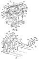
- Fig. 1 is a perspective view of a patient-support apparatus according to the present invention showing a base, a patient support carried above the base, and an isolation chamber enclosed by an overlying canopy, a pair of transparent side guard panels, and a pair of transparent end guard panels;
- Fig. 2 is perspective view of the patient-support apparatus of Fig. 1, with portions broken away showing the patient support including an upper surface and a tower extending upwardly from the upper surface, one of the end guard panels having a transverse portion adjacent to the tower, a noise and light monitor unit spaced apart from the tower, and a cable extending between the tower and the noise and light monitor unit;
- Fig. 3 is a rear elevation view of the noise and light monitor unit of Fig. 2 showing the noise and light monitor unit including a box having a cord recess formed therein and a cord wrap member around which the cord wraps, the cord wrap member being in a first position situated inside the cord recess;
- Fig. 4 is a side elevation view of the noise and light monitor unit of Fig. 3, with portions broken away, showing the cord wrap member being movable between the first position (in solid) and a second position (in phantom), the cord wrap member being configured to hook onto either of the side guard panels when in the second position;
- Fig. 5 is a top plan view of the patient-support apparatus of Fig. 1, with portions broken away, showing the cord having sufficient length to allow the noise and light monitor unit to be mounted to the end guard panel at a foot end of the patient support;
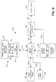
- Fig. 6 is a block diagram of the portion of an electrical system of the patient-support apparatus of Fig. 1 associated with the noise and light monitor unit;
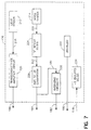
- Fig. 7 is a block diagram of a sub-portion of the electrical system contained within the noise and light monitor unit;
- Fig. 8 is a block diagram of a sub-portion of the electrical system contained within a patient environmental management unit of the electrical system; and
- Fig. 9 is a flow chart illustrating the steps performed by the portion of the electrical system associated with the noise and light monitor unit.
-
- A thermal support apparatus or patient-
support apparatus 20, such as an infant warming device or incubator, includes abase 22, a plurality ofcastors 24 extending downwardly frombase 22, and an infant supporting portion orpatient support 26 supported abovebase 22 as shown in Fig. 1.Patient support 26 includes apedestal 28 coupled tobase 22 for vertical movement, aplatform tub 30 supported bypedestal 28, and amattress 32 supported onplatform tub 30. Mattress 32 has an upwardly facing patient-support surface 33. Patient-support apparatus 20 also includes acanopy support arm 34 including a telescopingvertical arm 36 and ahorizontal overhead arm 38. Acanopy 40 is coupled tooverhead arm 38 and is positioned to lie aboveplatform tub 30. Canopy 40 includes a pair ofcanopy halves 42 coupled tooverhead arm 38 for pivoting movement between a lowered position shown in Fig. 1 and a raised position (not shown). - A pair of transparent
side guard panels 44 and a pair of transparentend guard panels 46 extend upwardly fromplatform tub 30 as shown in Fig. 1.Side guard panels 44 andend guard panels 46 cooperate withcanopy halves 42 andoverhead arm 38 to provide patient-support apparatus 20 with an isolation chamber.Side guard panels 44 are formed to include a pair of access ports that are normally closed by access door assemblies 48. Access door assemblies 48 includedoor panels 49 that can be opened to allow access to a patient, such as an infant, supported bythermal support apparatus 20 within the isolation chamber. Eachend guard panel 46 is formed to include at least one U-shaped window and a pass-throughgrommet 50 is positioned to lie in each U-shaped window. Wires and tubes (not shown) can be routed into the isolation chamber through pass-throughgrommets 50. - Patient-
support apparatus 20 includes auser interface panel 52 for monitoring various systems that control the temperature and humidity of the isolation chamber and for allowing caregivers to input various control parameters into memory of a control system of patient-support apparatus 20. Patient-support apparatus 20 also includes ahumidifier module 54 that can be filled with water and inserted into a humidifier compartment ofplatform tub 30. Heated air is blown throughhumidifier module 54 and directed into the isolation chamber. Atower 56 is positioned to lie in the isolation chamber. Tower 56 supports various sensor modules or units, such as a noise andlight monitor unit 58 and a patient environmental management (PEM)unit 59, and also provides a return-air path for the air being circulated through the isolation chamber. -
Hinges 60 are provided so thatside guard panels 44 and theend guard panel 46 at a foot end ofpatient support 26 can pivot downwardly away fromcanopy 40 to provide increased access to the infant supported by patient-support apparatus 20. Up and down buttons (not shown) can be pressed to extend and retractvertical arm 36 ofcanopy support arm 34, thereby raising and lowering, respectively,overhead arm 38 andcanopy 40. Patient-support apparatus 20 includes an uppedal 62 that can be depressed to raisepatient support 26 relative tobase 22 and adown pedal 64 that can be depressed tolower patient support 26 relative tobase 22. Patient-support apparatus 20 also includes aside bumper 66 that protectspedals base 22 andpedestal 28, from inadvertent impact.Platform tub 30 is formed to include ahandle 68 on each side ofcanopy support arm 34.Handles 68 can be grasped by a caregiver to maneuver patient-support apparatus 20 during transport. - Patient-
support apparatus 20 includestower 56, noise andlight monitor unit 58, andPEM unit 59 as previously described.Tower 56 extends upwardly from anupper surface 70 ofpatient support 26 adjacent to a mattress well 72 ofplatform tub 30 as shown in Fig. 2.Tower 56 includes a flatfront wall 74 and a pair ofvertical rails 76 appended tofront wall 74.Rails 76 are transversely spaced apart to define a unit-receivingspace 78 therebetween.PEM unit 59 is semi-permanently mounted to tower 56 so that a portion ofPEM unit 59 is received in unit-receivingspace 78 and a portion ofPEM unit 59 is positioned to lie outside unit-receivingspace 78. -
PEM unit 59 has a bottom surface (not shown) abuttingupper surface 70 ofpatient support 26 and an upwardly-facingtop surface 80 as shown in Fig. 2.PEM unit 59 includes an interior compartment (not shown) in which PEM electronics are situated.PEM unit 59 includes a temperatureprobe connector port 84 to which one end of a temperature probe (not shown) connects to provide a patient-temperature reading throughconnector port 84 to the PEM electronics when another end of the temperature probe is attached to the patient.PEM unit 59 also includes a weighscale connector port 82 to which a cord of a weigh scale (not shown) underlyingmattress 32 is connected to provide a patient-weight reading throughconnector port 82 to the PEM electronics. - Noise and
light monitor unit 58, hereinafter referred to asunit 58, includes a mouse orbox 86 having a mountinglug 88 appended to each of a pair ofside walls 90 thereof as shown in Figs. 2 and 3. An upper end of eachvertical rail 76 is formed to include a mountingnotch 92 as shown in Figs. 2 and 5.Unit 58 is selectively attachable to and detachable fromtower 56. Whenunit 58 is attached to tower 56, a portion ofunit 58 is received in unit-receivingspace 78, abottom wall 94 ofbox 86 rests upon upwardly-facingsurface 80 ofPEM unit 59, and lugs 88 are received innotches 92 to secureunit 58 to tower 56.Box 86 includes atop wall 96 and afront wall 98, each of which are positioned to lie outside unit-receivingspace 78 whenunit 58 is attached to tower 56. -
PEM unit 59 includes a pair of transversely spaced-apartside walls 100 and afront wall 110 extending transversely betweenside walls 100 as shown in Fig. 2. Whenunit 58 is attached to tower 56side walls 90 ofbox 76 are substantially coplanar withrespective side walls 100 ofPEM unit 59. In addition,front wall 110 ofPEM unit 59 has a curved "double-lobed" contour andfront wall 98 ofunit 58 has a curved "single-lobed" contour that is substantially consistent with the curved "double-lobed" contour offront wall 110 ofPEM unit 59. Thus,unit 58 nests within unit-receivingspace 78 atopPEM unit 59 in an aesthetically pleasing manner when attached to tower 56. -
Tower 56 provides a return-air path for the air being circulated through the isolation chamber as previously described.Tower 56 includes a pair of transversely spaced-apartside walls 112, each of which is integrally appended tofront wall 74.Tower 56 also includes aback wall 114 appended toside walls 112 and an inclinedtop wall 116 integrally connectingwalls Walls tower 56 with an internal air passage andfront wall 74 is formed to include arectangular vent aperture 118 adjacent totop wall 116 as shown in Fig. 2. Whenunit 58 is attached to tower 56,top wall 96 ofbox 86 is positioned to lie beneathvent aperture 118 so thatunit 58 does not obstructvent aperture 118. An air circulation system of patient-support apparatus 20 includes a fan (not shown) in an internal compartment ofplatform tub 30. The fan operates to move air from the isolation chamber throughvent aperture 118, into the internal air passage oftower 56, through channels (not shown) that surround mattress well 72, and then back into the isolation chamber through a plurality ofair vent slots 120, shown in Fig. 5, formed intop surface 70 ofpatient support 26. - The
end guard panel 46 at a head end ofpatient support 26 includes a largetransverse panel 122 and a pair ofsmall panels 124 that are appended to outer ends ofpanel 122 and that extend longitudinally frompanel 122 toward the foot end ofpatient support 26 as shown in Fig. 2.Tower 56 includes a mountingplate 126 appended to backwall 114 as shown in Figs. 2 and 5.Panel 122 is formed to include anedge 128, shown in Fig. 5, that defines a somewhat U-shaped mounting slot inpanel 122. When mountingplate 126 oftower 56 is received in the mounting slot ofpanel 122, engagement ofedge 128 ofpanel 122 with mountingplate 126, prevents transverse movement ofpanels patient support 26. Mountingplate 126 is formed to include a pair of outwardly extendingribs 130 as shown in Fig. 5. Portions ofpanel 122 adjacent to edge 128 are trapped betweenribs 130 and back wall of 114 oftower 56 so that longitudinal movement ofpanels patient support 26 is prevented when mounting plate is received in the mounting slot ofpanel 122.Panels patient support 26 until mountingplate 126 is no longer received in the mounting slot ofpanel 122 and thenpanels patient support 26 andtower 56. - An
electrical cord 132 connectsunit 59 toPEM unit 59 as shown in Figs. 2 and 5.Unit 58 includes noise and light monitor circuitry that is contained in aninterior region 134, shown in Fig. 4, ofbox 86.Electrical cord 132 interconnects the PEM electronics that are housed inPEM unit 59 and the noise and light monitor circuitry that is housed ininterior region 134 ofbox 86.Top wall 80 ofPEM unit 59 is formed to include anotch 136 andfront wall 74 oftower 56 is formed to include anotch 138 that is adjacent to notch 136 as shown in Fig. 2. A back wall (not shown) ofPEM unit 59 abutsfront wall 74 oftower 56 andelectrical cord 132 is routed throughnotches PEM unit 59 andtower 56.Electrical cord 132 enters the interior compartment ofPEM unit 59 though the back wall thereof. By routing electrical 132 in this manner,electrical cord 132 is prevented from inadvertently disconnecting from the PEM electronics. -
Box 86 includes aback cover 140 coupled towalls screws 142, which are arranged at the corners ofback cover 140 as shown in Fig. 3. Back cover 140 includes aback surface 144 and alarge cord recess 146 formed in the central region ofback surface 144. In addition,back cover 140 includes anotch 148 formed in a perimetral potion ofback surface 144 adjacent tobottom wall 92 and atransition recess 150 extending betweennotch 148 andcord recess 146 as shown in Figs. 3 and 4. Back cover 140 seals againstwalls interior region 134 ofbox 86. -
Unit 58 includes acord wrap member 152 having afirst panel 154 and asecond panel 156 appended tofirst panel 154 and extending therefrom in a perpendicular arrangement as shown in Fig. 4.Cord wrap member 152 is pivotably coupled toback cover 140 ofbox 86 by a pair ofpivot posts 158 that are appended tofirst panel 154 as shown in Fig. 3.Cord wrap member 152 is pivotable between a stored position, shown in Figs. 3 and 4, and a flipped-out position, shown in Fig. 4 (in phantom). Whencord wrap member 152 is in the stored position,first panel 154 is flush withback surface 144 ofback cover 140 andsecond panel 156 is positioned to lie insiderecess 146. Whencord wrap member 152 is in the flipped-out position,first panel 154 extends away fromback cover 140 and second panel is positioned to lieoutside recess 146. -
First panel 154 includes a pair of oppositely extendingtabs 160 andsecond panel 156 includes a pair of oppositely extendingtabs 162 that are spaced apart fromtabs 160 to define respective cord wrap spaces therebetween as shown in Fig. 3. Whenunit 58 is attached to tower 56,cord wrap member 152 is in the stored position having a majority ofcord 132 wrapped aroundsecond panel 156 through the cord wrap spaces betweentabs cord 132 is routed fromcord recess 146 throughtransition recess 150, throughnotch 148, and intoPEM unit 59 whenunit 58 is mounted to tower 56. Aftercord 132 has been wrapped aroundsecond panel 156 ofcord wrap member 152 as much as possible and beforeunit 58 is attached to tower 56, a small portion ofcord 132 still extends fromunit 58 tonotches Transition recess 150 is spherically-shaped so that this small amount ofcord 132 can move throughnotch 148 and intotransition recess 150 during the final stages of attachingunit 58 to tower 56. Whenunit 58 is finally attached to tower 56, backsurface 144 ofback cover 140 abutsfront wall 74 oftower 56 and a very small portion ofcord 132 is received innotch 148. - When
unit 58 is detached fromtower 56,cord wrap member 152 is moved to the flipped-out position andcord 132 is unwrapped fromsecond panel 156.Cord 132 is sufficiently long to allowunit 58 to be placed anywhere on patient-support surface 33 or the portion ofupper surface 70 encompassed by side andend guard panels Cord wrap member 152 is configured to allowunit 58 to be hung along the top edge of either ofside guard panels 44, as shown in Fig. 4 (in phantom), or along the top edge of either ofend guard panels 46 as shown in Fig. 5.Cord wrap member 152 can be used to hangunit 58 on other structures (not shown) as well. Alternatively, aftercord 132 is unwrapped fromsecond panel 156,cord wrap member 152 can be returned to the stored position andunit 58 can be placed upon eithermattress 32 orpatient support 26 so thatback surface 144 ofback cover 140 abuts eithersurface 33 orsurface 70, respectively. - Patient-
support apparatus 20 includes PEM electronics situated in an internal compartment ofPEM unit 59 and noise and light monitor circuitry situated ininterior region 134 ofbox 86 as previously described. The PEM electronics and the noise and light monitor circuitry are each separate sub-portions of a large overall electrical system that is located throughout patient-support apparatus 20. A block diagram showing aportion 164 of the large overall electrical system of patient-support apparatus 20 that is associated with noise andlight monitor unit 58, hereinafter referred to ascircuit 164, is illustrated in Fig. 6. -
Circuit 164 includes amicrocontroller 166 that receives power from apower board 168 as shown in Fig. 6.Microcontroller 166 is a microprocessor based controller having various input ports for receiving signals from other components of the overall electrical system and various output ports for sending signals to other components of the overall electrical system as is described in detail in PCT publication No. WO 97/11663 published April 3, 1997, the specification of which is expressly incorporated herein by reference.Power board 168 receives power via apower line 169 from external power, indicated byblock 170 of Fig. 6.External power 170 is standard 120 Volt AC power.Power board 168 includes conventional circuitry that converts the supplied external power into, for example, ± 12 Volt DC and ± 5 Volt DC power which is suitable for operating the various electrical circuit components contained inmicrocontroller 166 and contained elsewhere in the overall electrical system.Power board 168 supplies the converted power tomicrocontroller 166 via apower line 171. -
Microcontroller 166 is coupled to the PEM electronics, indicated byblock 172 in Figs. 6 and 8, by a combined power anddata line 174. Control data and sensor data is transmitted betweenmicrocontroller 166 andPEM electronics 172 vialine 174 and power for thePEM electronics 172 is supplied frommicrocontroller 166 toPEM electronics 172 vialine 174 as well. The noise and light monitor circuitry, indicated byblock 176 in Figs. 6 and 7, is coupled toPEM electronics 172 bycord 132 as previously described.Cord 132 includes apower line 178 over which +5 Volt DC power is supplied to noise andlight monitor circuitry 176.Cord 132 also includes wires over which an "installed"signal 180, an "average noise"signal 182, a "peak noise"signal 184, and a "light intensity"signal 186 are sent toPEM electronics 172 from noise andlight monitor circuitry 176, hereinafter referred to asmonitor circuitry 176. - Although
monitor circuitry 176 is coupled toPEM electronics 172 bycord 132, other means for couplingmonitor circuitry 176 toPEM electronics 172 or to any other portion ofcircuit 164 are possible. For example, in an alternative embodiment,unit 58 is a cordless unit having a transmitter that transmits data to a receiver on patient-support apparatus 20 in a conventional manner, such as by use of infrared signals, radio frequency signals, or ultrasonic signals. The receiver then couples tocircuit 164 to provide signal inputs tocircuit 164. -
Overhead arm 38 includes a number of compartments (not shown) in which overhead arm circuitry, indicated byblock 188 in Fig. 6, is situated.Microcontroller 166 is coupled tooverhead arm circuitry 188 by adata line 190. Control data and feedback data is transmitted betweenmicrocontroller 166 andoverhead arm circuitry 188 vialine 190. In addition,power board 168 is coupled tooverhead arm circuitry 188 by apower line 192.Overhead arm 38 also includes a compartment (not shown) in which an alert light, indicated byblock 194 in Fig. 6, is situated. In a preferred embodiment,alert light 194 is a white light that is covered by a slightly opaquelight cover 198, shown in Fig. 1.Alert light 194 is coupled tooverhead arm circuitry 188 by an ON/OFF line 196. -
User interface panel 52 is coupled tomicrocontroller 166 via adata line 200 as shown in Fig. 6.User interface panel 52 includes a keypad, an LED display screen, and an LCD display screen (all of which are not shown).User interface panel 52 also includes arotatable knob 210 as shown in Fig. 1.Knob 210 is used to scroll through various menus that are displayed on the LCD display screen and buttons of the keypad are pressed to adjust various parameters that are stored in memory ofmicrocontroller 166. Thus,user interface panel 52 permits a caregiver to input information intomicrocontroller 166 throughdata line 200. In addition,microcontroller 166 transmits data, such as temperature and humidity readings, touser interface panel 52 and the data is displayed to the caregiver on the LED screen ofuser interface panel 52. - One of the menu screens that can be selected by rotation of
knob 210 allows the caregiver to input a noise threshold level and a light threshold level. In addition, the caregiver is permitted to select whether the noise threshold level is with respect to a peak noise level or an average noise level. In a preferred embodiment, the caregiver can select a light threshold level that is anywhere between about 20 ft. candles and about 250 ft. candles (about 200 lux and about 2700 lux) and the caregiver can select a noise threshold level that is anywhere between about 30 dBA and about 120 dBA.Circuit 164 operates so that, when either of the selected noise and light threshold levels is exceeded,alert light 194 is flashed to alert the caregiver of the situation. Thus,alert light 194 provides patient-support apparatus 20 with a noise and light indicator. -
Monitor circuitry 176 includes a light sensor, indicated byblock 212 in Fig. 7, and a noise sensor, indicated byblock 214 in Fig. 7. In a preferred embodiment,light sensor 212 is a commercially available Centronic Model No. BPW-21P photodiode andnoise sensor 214 is a commercially available Gentex Model No. 3072 microphone.Light sensor 212 is covered by a substantially transparent,protective dome 216 extending fromfront wall 98 ofbox 86 as shown in Figs. 2, 4, and 5. In addition,front wall 98 ofbox 86 is formed to include a small aperture (not shown) through which sound waves travel to reachnoise sensor 214. -
Light sensor 212 produces anoutput signal 218, shown in Fig. 7, the magnitude of which is based upon the intensity of the light that passes throughprotective dome 216 and reacheslight sensor 212.Monitor circuitry 176 includes a transconductance amplifier circuit, indicated byblock 220 of Fig. 7.Output signal 218 is amplified bytransconductance amplifier circuit 220 to producelight intensity signal 186 which is coupled toPEM electronics 172 as previously described. -
Noise sensor 214 produces anoutput signal 222, shown in Fig. 7, the magnitude of which is based upon the sound pressure level of the sound waves that pass through the small aperture infront wall 98 ofbox 86 and reachnoise sensor 214.Monitor circuitry 176 includes an "A" weight filter, indicated byblock 224 of Fig. 7.Filter 224 is constructed to comply with ISO "A" weighting standards which relate to converting AC voltage signals to dBA signals and which are well known to those skilled in the art.Filter 224 convertsoutput signal 222 into afiltered signal 226 which is coupled to an RMS-to-dB conversion circuit, indicated byblock 228 of Fig. 7. - RMS-to-
dB conversion circuit 228 converts filteredsignal 226 intopeak noise signal 184 which is, in turn, coupled toPEM electronics 172 as previously described.Peak noise signal 184 is also coupled to averaging circuitry, indicated byblock 230 of Fig. 7. Averagingcircuitry 230 converts peaknoise signal 184 intoaverage noise signal 182 which is, in turn, coupled to PEM electronics as also previously described.Monitor circuitry 176 further includes an installed connector port, indicated byblock 232 of Fig. 7, and -5V isolated DC/DC circuitry, indicated byblock 234 of Fig. 7.Installed connector port 232 is an active-low terminal that couples to ground to produce installedsignal 180. DC/DC circuitry 234 routes power frompower line 178 to various components ofmonitor circuitry 176 and also operates to "float"monitor circuitry 176 relative to true ground. Floatingmonitor circuitry 176 in this manner prevents the patient supported by patient-support apparatus 20 from receiving inadvertent electrical shocks from the electrical components ofunit 58. -
PEM electronics 172 includes noise and light conditioning circuitry, indicated byblock 236 of Fig. 8.Signals conditioning circuitry 236 as are additional signals (not shown) from other types of patient environmental sensors, such as temperature and humidity sensors.Signals conditioning circuitry 236 to respective signals of appropriate dynamic range.PEM electronics 172 includes an A/D convertor, indicated byblock 238 of Fig. 8. A/D convertor 238 receives the modifiedsignals data line 240 which, for the sake of simplicity, has been illustrated as a single line that carries all of the modifiedsignals -
PEM electronics 172 includes a PEM ID code status circuit, indicated byblock 242 of Fig. 8.Signal 180 frommonitor circuitry 176 is coupled tocode status circuit 242 along with other signals (not shown) from other components of the overall electrical circuit, such as a weigh scale and a baby temperature probe.PEM electronics 172 also includes a serial port interface (SPI) select circuit, indicated byblock 244 of Fig. 8. SPIselect circuit 244 provides afirst selection signal 246 tocode status circuit 242 and asecond selection signal 248 to A/D converter 238. The first and second selection signals 246, 248 are controlled to coordinate the timing and sequence of the data that is ultimately transmitted tomicrocontroller 166 fromPEM electronics 172 on power anddata line 174. -
PEM electronics 172 further includes an optical isolation circuit, indicated byblock 250 of Fig. 8.Optical isolation circuit 250 is coupled tomicrocontroller 166 via power anddata line 174.Optical isolation circuit 250 is also coupled to a DC converter and regulator, indicated byblock 252 of Fig. 8, by apower line 254.Optical isolation circuit 250 routes power from power anddata line 174 throughpower line 254 to DC converter andregulator 252 which then routes power to various components ofPEM electronics 172. DC converter andregulator 252 also routes power to monitorcircuit 176 onpower line 178. -
Optical isolation circuit 250 is coupled to A/D converter 238 via asensor data line 256. In addition,optical isolation circuit 250 is coupled to SPIselect circuit 244 via acoordination data line 258. Patient environment signals, such as those indicating the noise and light levels sensed bynoise sensor 214 andlight sensor 212, are transmitted from A/D converter 238 tooptical isolation circuit 250 onsensor data line 256.Optical isolation circuit 250 then operates to forward the patient environment signals tomicrocontroller 166 on power anddata line 174.Microcontroller 166 sends a coordination signal tooptical isolation circuit 250 online 174 andoptical isolation circuit 250 operates to forward the coordination signal to SPIselect circuit 244 oncoordination data line 258. The coordination signal frommicrocontroller 166 indicates toPEM electronics 172 which patient environment signal to send back tomicrocontroller 166. The primary purpose ofoptical isolation circuit 250 is to "float"PEM electronics 176 relative to true ground. Floating PEM electronics in this manner prevents the patient supported by patient-support apparatus 20 from receiving inadvertent electrical shocks from the electrical components ofPEM electronics 172. -
Circuit 164 includes a data port, indicated byblock 260 of Fig. 6, which is coupled tomicrocontroller 166 via adata line 262.Microcontroller 166 sends the patient environment signals received fromPEM electronics 172 todata port 260. External data collection and display equipment (not shown) can be connected tocircuit 164 atdata port 260 and the patient environment signals can be recorded so that caregivers can study, for example, the time history of noise and light levels to which the patient is exposed. -
Microcontroller 166 is coupled tooverhead arm circuitry 188 bydata line 190 andoverhead arm circuitry 188 is coupled to alert light 194 by ON/OFF line 196 as previously described. Whennoise sensor 214, in cooperation with the associated components ofmonitor circuitry 176 andPEM electronics 172, indicates tomicrocontroller 166 that the measured peak or average noise level exceeds the selected noise threshold level,microcontroller 166 sends a signal tooverhead arm circuitry 188 to flashalert light 194. In addition, whenlight sensor 212, in cooperation with the associated components ofmonitor circuitry 176 andPEM electronics 172, indicates tomicrocontroller 166 that the measured light level exceeds the selected light threshold level,microcontroller 166 sends a signal tooverhead arm circuitry 188 to flashalert light 194. - Fig. 9 illustrates a flow chart of the steps performed by
circuit 164 of patient-support apparatus 20 to determine whether to flashalert light 194. First,circuit 164 determines whether noise andlight monitor unit 58 is installed, as indicated atblock 270. Ifunit 58 is not installed,microcontroller 166 signalsoverhead arm circuitry 188 vialine 190 and then,overhead arm circuitry 188 signals alert light 194 vialine 196 to remain in an OFF condition, as indicated atblock 272. Ifunit 58 is installed,circuit 164 determines atblock 274 whether the light level sensed bysensor 212 is above the selected light threshold level. If the light level sensed bysensor 212 is above the selected light threshold level,microcontroller 166 signalsoverhead arm circuitry 188 vialine 190 and then,overhead arm circuitry 188 signals alert light 194 vialine 196 to alternately flashalert light 194 between ON and OFF conditions, as indicated atblock 276. - If the light level is not above the selected light threshold level,
circuit 164 determines atblock 278 whether a caregiver has indicated that the peak noise level is the desired noise level to be monitored bycircuit 164. If the peak noise level is the noise level to be monitored,circuit 164 determines atblock 280 whether the noise level sensed bysensor 214 is above the selected peak noise threshold level. If the noise level sensed bysensor 214 is above the selected peak noise threshold level,microcontroller 166 signalsoverhead arm circuitry 188 vialine 190 and then,overhead arm circuitry 188 signals alert light 194 vialine 196 to alternately flashalert light 194 between ON and OFF conditions, as indicated atblock 276. If the peak noise level sensed bysensor 214 is below the selected peak noise threshold level,microcontroller 166 signalsoverhead arm circuitry 188 vialine 190 and then,overhead arm circuitry 188 signals alert light 194 vialine 196 to remain in an OFF condition, as indicated atblock 272. - If the peak noise level is not the noise level to be monitored,
circuit 164 determines atblock 282 whether a caregiver has indicated that the average noise level is the desired noise level to be monitored bycircuit 164. If the average noise level is the noise level to be monitored,circuit 164 determines atblock 284 whether the noise level sensed bysensor 214 is above the selected average noise threshold level. If the noise level sensed bysensor 214 is above the selected average noise threshold level,microcontroller 166 signalsoverhead arm circuitry 188 vialine 190 and then,overhead arm circuitry 188 signals alert light 194 vialine 196 to alternately flashalert light 194 between ON and OFF conditions, as indicated atblock 276. If the average noise level sensed bysensor 214 is below the selected average noise threshold level,microcontroller 166 signalsoverhead arm circuitry 188 vialine 190 and then,overhead arm circuitry 188 signals alert light 194 vialine 196 to remain in an OFF condition, as indicated atblock 272. - Although the invention has been described in detail with reference to a certain preferred embodiment, variations and modifications exist within the scope and spirit of the invention as described and as defined in the following claims.
Claims (6)
- A patient-support assembly comprising a patient support, a side guard panel coupled to the patient support and having a first surface and a second surface spaced-apart from the first surface, the side guard panel including an edge defining a window in the side guard panel, the side guard panel having a thickness between a maximum thickness and a minimum thickness, and a grommet received in the window of the side panel, the grommet including a rim configured to engage the edge defining a window, a plurality of flexible flaps coupled to the rim and arranged to substantially fill the window, a first lip extending from the rim and arranged to engage the first surface of the side guard panel, and a second lip extending from the rim and arranged to engage the second surface of the side guard panel, the second lip having a first portion adjacent to the rim and a second portion spaced apart from the rim and thicker than the first portion, the second lip being flexible to sealingly engage the second surface of the side guard panel. regardless of the thickness of the side guard panel within a tolerance range between the maximum and minimum thicknesses.
- A patient-support apparatus comprising a base, a patient support carried above the base, the patient support including a platform tub and a platform cover, the platform tub including a first wall and a second wall spaced apart from the first wall to define an air flow channel therebetween, the platform cover being mounted to the platform tub to cover the air flow channel, the platform cover being formed to include a plurality of air vent slots, and an air flow guide including an elongated vent rail appended to the platform cover and extending into the air flow channel and an elongated vent panel pivotably coupled to the platform cover, the vent rail being formed to include a plurality of vent channels separated by abutment surfaces, the vent channels being in fluid communication with respective air vent slots, and the vent panel being pivotable between a first position abutting the abutment surfaces and a second position moved away from the vent rail to provide increased access to the vent channels.
- A patient-support apparatus comprising a base, a patient support supported above the base and having a patient-support surface, a side guard panel coupled to the patient support adjacent to the patient-support surface, the side guard panel being formed to include an access port, and an access door assembly including a mounting block, a door panel, and a lever with a locking member, the mounting block being coupled to the side guard panel, the door panel having a first end pivotably coupled to the mounting block and a second end spaced apart from the first end, the door panel being movable between a closed position in which the door panel closes the access port and an opened position in which the door panel is spaced apart from the side guard panel so that the access port is opened, the lever having a first end pivotably coupled to the mounting block and a second end spaced apart from the first end, the lever being movable between a locking position in which the locking member engages the door panel to lock the door panel in the closed position and a releasing position in which the locking member is spaced apart from the door panel to unlock the door panel, the door panel having a portion configured to engage the lever to move the lever from the locking position to the releasing position when the second end of the door panel is moved toward the side guard panel.
- A patient-support apparatus comprising a base, a patient support supported above the base and having a patient-support surface, a side guard panel coupled to the patient support adjacent to the patient-support surface, the side guard panel being formed to include an access port having a first end and a second end, and an access door assembly including a door panel and a lever with a locking member, the door panel having a first end pivotably coupled to the side guard panel adjacent to the first end of the access port and a second end spaced apart from the first end, the door panel being movable between a closed position in which the door panel closes the access port and an opened position in which the door panel is spaced apart from the side guard panel so that the access port is opened, the lever having a first end pivotably coupled to the side guard panel adjacent to the first end of the access port and a second end spaced apart from the first end, the lever being movable between a locking position in which the locking member engages the door panel to lock the door panel in the closed position and a releasing position in which the locking member is spaced apart from the door panel to unlock the door panel.
- A patient-support apparatus comprising a base, a patient support carried above the base, an isolation chamber on the patient support, a system for monitoring at least one environmental condition in the isolation chamber, and a user interface panel having at least one button for entering system inputs and displays for observing system outputs, the user interface panel being rotatively mounted to the patient support through a rotatable member for pivoting movement about a vertical axis through about 180° so as to be accessible from opposite sides of the patient support, and a hinge connecting the user interface panel to the rotatable member to permit angling of the user interface panel with respect to the patient support.
- A patient-support apparatus comprising a base, a patient support carried above the base, a controller configured to control at least one function on the patient support, and a user interface panel including a display and at least one button configured to provide an input signal to the controller, the user interface panel being coupled to the patient support by a resistive hinge configured to resist pivoting of the user interface panel in response to normal actuating forces applied to the at least one button of the user interface panel and configured to allow pivoting of the user interface panel in response to forces applied to the user interface panel that exceed the normal actuating forces.
Applications Claiming Priority (3)
| Application Number | Priority Date | Filing Date | Title |
|---|---|---|---|
| US926381 | 1997-09-09 | ||
| US08/926,381 US5971913A (en) | 1995-09-25 | 1997-09-09 | Noise and light monitor apparatus |
| EP98945950A EP1011590B1 (en) | 1997-09-09 | 1998-09-09 | Noise and light monitor apparatus |
Related Parent Applications (1)
| Application Number | Title | Priority Date | Filing Date |
|---|---|---|---|
| EP98945950A Division EP1011590B1 (en) | 1997-09-09 | 1998-09-09 | Noise and light monitor apparatus |
Publications (2)
| Publication Number | Publication Date |
|---|---|
| EP1520571A2 true EP1520571A2 (en) | 2005-04-06 |
| EP1520571A3 EP1520571A3 (en) | 2005-05-11 |
Family
ID=25453134
Family Applications (2)
| Application Number | Title | Priority Date | Filing Date |
|---|---|---|---|
| EP98945950A Expired - Lifetime EP1011590B1 (en) | 1997-09-09 | 1998-09-09 | Noise and light monitor apparatus |
| EP04078246A Withdrawn EP1520571A3 (en) | 1997-09-09 | 1998-09-09 | Noise and light monitor apparatus |
Family Applications Before (1)
| Application Number | Title | Priority Date | Filing Date |
|---|---|---|---|
| EP98945950A Expired - Lifetime EP1011590B1 (en) | 1997-09-09 | 1998-09-09 | Noise and light monitor apparatus |
Country Status (8)
| Country | Link |
|---|---|
| US (1) | US5971913A (en) |
| EP (2) | EP1011590B1 (en) |
| JP (1) | JP2001515755A (en) |
| AU (1) | AU9308198A (en) |
| CA (1) | CA2302734A1 (en) |
| DE (1) | DE69827813T2 (en) |
| NO (1) | NO20001209L (en) |
| WO (1) | WO1999012509A1 (en) |
Families Citing this family (45)
| Publication number | Priority date | Publication date | Assignee | Title |
|---|---|---|---|---|
| EP1231883B1 (en) | 1999-11-15 | 2008-09-10 | Draeger Medical Systems, Inc. | Infant care apparatus with movable infant support |
| US6880188B1 (en) | 1999-11-15 | 2005-04-19 | Draeger Medical Infant Care, Inc. | Infant care apparatus with movable infant support |
| JP2002011055A (en) * | 2000-06-28 | 2002-01-15 | Atom Medical Corp | Infant incubator |
| US6409654B1 (en) * | 2000-08-15 | 2002-06-25 | Mcclain Anthony | Incubator system with monitoring and communicating capabilities |
| ATE418314T1 (en) * | 2001-02-06 | 2009-01-15 | Draeger Medical Systems Inc | INCUBATOR FOR NON-CONTACT MEASUREMENT AND MONITORING |
| US6686839B2 (en) * | 2001-04-04 | 2004-02-03 | International Business Machines Corporation | Method and system for noise notification |
| CA2443958C (en) | 2001-04-16 | 2007-06-26 | Hill-Rom Services, Inc. | Infant support thermal control system and method |
| CA2445520A1 (en) | 2001-05-15 | 2002-11-21 | Hill-Rom Services, Inc. | Apparatus and method for patient data management |
| US6829796B2 (en) | 2001-10-02 | 2004-12-14 | Hill-Rom Services, Inc. | Integrated barrier and fluid supply for a hospital bed |
| AU2002332029A1 (en) | 2001-10-05 | 2003-04-22 | Hill-Rom Services, Inc. | Patient-support device and docking cart combination |
| WO2004026214A1 (en) | 2002-09-18 | 2004-04-01 | Hill-Rom Services, Inc. | Infant thermal support device having drain system |
| CA2505102A1 (en) * | 2005-03-07 | 2006-09-07 | Hill-Rom Services, Inc. | Footboard for a hospital bed |
| GB2439780B (en) * | 2006-07-04 | 2010-12-01 | Anachem Ltd | Controlled environment cabinet |
| US7904976B2 (en) * | 2007-04-27 | 2011-03-15 | Hill-Rom Services, Inc. | Endboard for a patient support |
| US20090069873A1 (en) * | 2007-08-28 | 2009-03-12 | Vreman Hendrik J | Transparent film for a phototherapy device |
| US20110113562A1 (en) * | 2009-11-16 | 2011-05-19 | Uzzle Thomas E | Endboard for person support apparatus |
| US10076266B2 (en) | 2010-07-07 | 2018-09-18 | Aspect Imaging Ltd. | Devices and methods for a neonate incubator, capsule and cart |
| US10499830B2 (en) | 2010-07-07 | 2019-12-10 | Aspect Imaging Ltd. | Premature neonate life support environmental chamber for use in MRI/NMR devices |
| IL226488A (en) | 2013-05-21 | 2016-07-31 | Aspect Imaging Ltd | Cradle for neonates |
| US11278461B2 (en) | 2010-07-07 | 2022-03-22 | Aspect Imaging Ltd. | Devices and methods for a neonate incubator, capsule and cart |
| DE202011051313U1 (en) | 2010-09-16 | 2011-11-23 | Aspect Magnet Technologies Ltd. | Closed life support system for premature babies |
| US10794975B2 (en) | 2010-09-16 | 2020-10-06 | Aspect Imaging Ltd. | RF shielding channel in MRI-incubator's closure assembly |
| US20130158339A1 (en) * | 2011-12-16 | 2013-06-20 | General Electric Company | System and Method of Infant Care Control and Workflow |
| US10110859B2 (en) * | 2013-06-11 | 2018-10-23 | Koninklijke Philips N.V. | System, method and device for monitoring light and sound impact on a person |
| US11278446B2 (en) | 2013-09-02 | 2022-03-22 | Aspect Imaging Ltd. | Active thermo-regulated neonatal transportable incubator |
| DE202013104934U1 (en) | 2013-11-03 | 2013-11-20 | Aspect Imaging Ltd. | Patiententransportinkubator |
| EP2905584B2 (en) * | 2014-02-07 | 2020-08-26 | Blueair AB | Detachable sensor module for an air treatment device |
| US10383782B2 (en) | 2014-02-17 | 2019-08-20 | Aspect Imaging Ltd. | Incubator deployable multi-functional panel |
| CN109416890B9 (en) * | 2016-07-07 | 2021-05-11 | 株式会社华尔卡 | Training device and training method for sealing construction |
| US10224135B2 (en) | 2016-08-08 | 2019-03-05 | Aspect Imaging Ltd. | Device, system and method for obtaining a magnetic measurement with permanent magnets |
| US11287497B2 (en) | 2016-08-08 | 2022-03-29 | Aspect Imaging Ltd. | Device, system and method for obtaining a magnetic measurement with permanent magnets |
| JP6851215B2 (en) * | 2017-02-13 | 2021-03-31 | パラマウントベッド株式会社 | Judgment device, judgment method and computer program |
| US11304865B2 (en) | 2017-06-27 | 2022-04-19 | Stryker Corporation | Patient support apparatus with adaptive user interface |
| US11810667B2 (en) | 2017-06-27 | 2023-11-07 | Stryker Corporation | Patient support systems and methods for assisting caregivers with patient care |
| US11382812B2 (en) | 2017-06-27 | 2022-07-12 | Stryker Corporation | Patient support systems and methods for assisting caregivers with patient care |
| US10811136B2 (en) | 2017-06-27 | 2020-10-20 | Stryker Corporation | Access systems for use with patient support apparatuses |
| US11484451B1 (en) | 2017-06-27 | 2022-11-01 | Stryker Corporation | Patient support apparatus user interfaces |
| US11202729B2 (en) | 2017-06-27 | 2021-12-21 | Stryker Corporation | Patient support apparatus user interfaces |
| US11096850B2 (en) | 2017-06-27 | 2021-08-24 | Stryker Corporation | Patient support apparatus control systems |
| US11337872B2 (en) | 2017-06-27 | 2022-05-24 | Stryker Corporation | Patient support systems and methods for assisting caregivers with patient care |
| US11052016B2 (en) | 2018-01-18 | 2021-07-06 | Aspect Imaging Ltd. | Devices, systems and methods for reducing motion artifacts during imaging of a neonate |
| CN109267901B (en) * | 2018-11-05 | 2024-04-16 | 力康华耀生物科技(上海)有限公司 | Operation window structure for infant incubator |
| US11166677B2 (en) * | 2019-03-06 | 2021-11-09 | General Electric Company | Systems and methods for monitoring a patient |
| CN111991161A (en) * | 2020-06-05 | 2020-11-27 | 刘雨露 | Insulation can with shading structure |
| JP7179111B2 (en) * | 2021-03-09 | 2022-11-28 | パラマウントベッド株式会社 | judgment device |
Citations (1)
| Publication number | Priority date | Publication date | Assignee | Title |
|---|---|---|---|---|
| WO1997011663A1 (en) | 1995-09-25 | 1997-04-03 | Hill-Rom, Inc. | Controller for a patient warming device |
Family Cites Families (15)
| Publication number | Priority date | Publication date | Assignee | Title |
|---|---|---|---|---|
| US3187744A (en) * | 1961-01-31 | 1965-06-08 | Air Reduction | Incubator |
| US3335713A (en) * | 1963-11-05 | 1967-08-15 | Air Shields | Infant incubator |
| JPS49122184A (en) * | 1973-03-28 | 1974-11-21 | ||
| US4121571A (en) * | 1977-01-28 | 1978-10-24 | Pickering Donald E | Transportable life support chamber, method and system |
| US4399823A (en) * | 1981-10-05 | 1983-08-23 | Air-Shields, Inc. | Apparatus for detecting probe dislodgement |
| IL75215A (en) * | 1985-05-16 | 1992-07-15 | Israel Atomic Energy Comm | Infant incubator |
| EP0460025A1 (en) * | 1989-02-27 | 1991-12-11 | Air-Shields, Inc. | Incubator with separated control and display module |
| US5162038A (en) * | 1989-12-04 | 1992-11-10 | Hill-Rom Company | Infant warmer open bed |
| US5081722A (en) * | 1991-03-13 | 1992-01-21 | Yu Yuan Chieh | Adjustable crib with vibrator, moisture sensor, fan, microphone and speaker |
| US5308310A (en) * | 1992-08-18 | 1994-05-03 | Vitaltrends Technology, Inc. | Plethysmograph system and air-tight sealing assembly therefor |
| US5339223A (en) * | 1993-03-24 | 1994-08-16 | Ohmeda Inc. | Servocontrol for fiberoptic phototherapy pad |
| US5446934A (en) * | 1993-11-30 | 1995-09-05 | Frazier; Richard K. | Baby monitoring apparatus |
| US5759149A (en) * | 1993-12-17 | 1998-06-02 | Hill-Rom, Inc. | Patient thermal support device |
| US5453077A (en) * | 1993-12-17 | 1995-09-26 | Hill-Rom Company, Inc. | Infant thermal support device |
| US5400425A (en) * | 1994-05-13 | 1995-03-21 | Ohmeda Inc. | Fiberoptic illuminator for infant care |
-
1997
- 1997-09-09 US US08/926,381 patent/US5971913A/en not_active Expired - Lifetime
-
1998
- 1998-09-09 EP EP98945950A patent/EP1011590B1/en not_active Expired - Lifetime
- 1998-09-09 DE DE69827813T patent/DE69827813T2/en not_active Expired - Lifetime
- 1998-09-09 WO PCT/US1998/018702 patent/WO1999012509A1/en active IP Right Grant
- 1998-09-09 AU AU93081/98A patent/AU9308198A/en not_active Abandoned
- 1998-09-09 CA CA002302734A patent/CA2302734A1/en not_active Abandoned
- 1998-09-09 JP JP2000510409A patent/JP2001515755A/en active Pending
- 1998-09-09 EP EP04078246A patent/EP1520571A3/en not_active Withdrawn
-
2000
- 2000-03-08 NO NO20001209A patent/NO20001209L/en not_active Application Discontinuation
Patent Citations (1)
| Publication number | Priority date | Publication date | Assignee | Title |
|---|---|---|---|---|
| WO1997011663A1 (en) | 1995-09-25 | 1997-04-03 | Hill-Rom, Inc. | Controller for a patient warming device |
Also Published As
| Publication number | Publication date |
|---|---|
| NO20001209D0 (en) | 2000-03-08 |
| DE69827813D1 (en) | 2004-12-30 |
| NO20001209L (en) | 2000-05-08 |
| JP2001515755A (en) | 2001-09-25 |
| US5971913A (en) | 1999-10-26 |
| AU9308198A (en) | 1999-03-29 |
| DE69827813T2 (en) | 2005-12-08 |
| WO1999012509A1 (en) | 1999-03-18 |
| CA2302734A1 (en) | 1999-03-18 |
| EP1011590A1 (en) | 2000-06-28 |
| EP1520571A3 (en) | 2005-05-11 |
| EP1011590B1 (en) | 2004-11-24 |
Similar Documents
| Publication | Publication Date | Title |
|---|---|---|
| EP1520571A2 (en) | Noise and light monitor apparatus | |
| US20220117813A1 (en) | Patient support with improved control | |
| EP1432374B1 (en) | Infant care apparatus | |
| CA2232819C (en) | Patient thermal support device | |
| CN103858076B (en) | configurable patient monitoring system | |
| EP1525842A1 (en) | Telemetry sensing system for infant care apparatus | |
| BR112013012329B1 (en) | SCREEN DEVICE FOR USE IN A PATIENT MONITORING SYSTEM AND PATIENT MONITORING SYSTEM | |
| US20080183029A1 (en) | Telemetry sensing system for infant care apparatus | |
| EP1231883B1 (en) | Infant care apparatus with movable infant support | |
| MXPA00002369A (en) | Noise and light monitor apparatus | |
| CN211409799U (en) | Multifunctional neonate warm-keeping table |
Legal Events
| Date | Code | Title | Description |
|---|---|---|---|
| PUAI | Public reference made under article 153(3) epc to a published international application that has entered the european phase |
Free format text: ORIGINAL CODE: 0009012 |
|
| PUAL | Search report despatched |
Free format text: ORIGINAL CODE: 0009013 |
|
| 17P | Request for examination filed |
Effective date: 20041223 |
|
| AC | Divisional application: reference to earlier application |
Ref document number: 1011590 Country of ref document: EP Kind code of ref document: P |
|
| AK | Designated contracting states |
Kind code of ref document: A2 Designated state(s): CH DE DK FR GB GR IT LI NL SE |
|
| AK | Designated contracting states |
Kind code of ref document: A3 Designated state(s): CH DE DK FR GB GR IT LI NL SE |
|
| RIN1 | Information on inventor provided before grant (corrected) |
Inventor name: NEWKIRK, DAVID C. Inventor name: KODY, JOHN J. Inventor name: DONNELLY, MICHAEL M. Inventor name: PROWS, D. SCOTT |
|
| AKX | Designation fees paid |
Designated state(s): DE GB |
|
| STAA | Information on the status of an ep patent application or granted ep patent |
Free format text: STATUS: THE APPLICATION IS DEEMED TO BE WITHDRAWN |
|
| 18D | Application deemed to be withdrawn |
Effective date: 20051112 |