EP1520720A2 - Image forming apparatus - Google Patents
Image forming apparatus Download PDFInfo
- Publication number
- EP1520720A2 EP1520720A2 EP04022285A EP04022285A EP1520720A2 EP 1520720 A2 EP1520720 A2 EP 1520720A2 EP 04022285 A EP04022285 A EP 04022285A EP 04022285 A EP04022285 A EP 04022285A EP 1520720 A2 EP1520720 A2 EP 1520720A2
- Authority
- EP
- European Patent Office
- Prior art keywords
- printing
- image forming
- forming apparatus
- printing part
- main body
- Prior art date
- Legal status (The legal status is an assumption and is not a legal conclusion. Google has not performed a legal analysis and makes no representation as to the accuracy of the status listed.)
- Granted
Links
- 238000007639 printing Methods 0.000 claims abstract description 323
- 230000007246 mechanism Effects 0.000 claims description 97
- 238000007641 inkjet printing Methods 0.000 claims description 61
- 238000007599 discharging Methods 0.000 claims description 12
- 230000008531 maintenance mechanism Effects 0.000 claims description 11
- 238000000034 method Methods 0.000 claims description 8
- 238000012423 maintenance Methods 0.000 abstract description 6
- 238000010586 diagram Methods 0.000 description 7
- 230000008439 repair process Effects 0.000 description 6
- 239000003086 colorant Substances 0.000 description 4
- 230000008569 process Effects 0.000 description 4
- 238000010276 construction Methods 0.000 description 3
- 230000003287 optical effect Effects 0.000 description 3
- 238000000926 separation method Methods 0.000 description 3
- 239000011111 cardboard Substances 0.000 description 2
- 239000011521 glass Substances 0.000 description 2
- 229920003002 synthetic resin Polymers 0.000 description 2
- 239000000057 synthetic resin Substances 0.000 description 2
- 230000009471 action Effects 0.000 description 1
- 230000003247 decreasing effect Effects 0.000 description 1
- 230000007613 environmental effect Effects 0.000 description 1
- 239000007788 liquid Substances 0.000 description 1
- 239000002184 metal Substances 0.000 description 1
- 238000012986 modification Methods 0.000 description 1
- 230000004048 modification Effects 0.000 description 1
- 230000000414 obstructive effect Effects 0.000 description 1
- 230000000630 rising effect Effects 0.000 description 1
- 238000005096 rolling process Methods 0.000 description 1
Images


Classifications
-
- B—PERFORMING OPERATIONS; TRANSPORTING
- B41—PRINTING; LINING MACHINES; TYPEWRITERS; STAMPS
- B41J—TYPEWRITERS; SELECTIVE PRINTING MECHANISMS, i.e. MECHANISMS PRINTING OTHERWISE THAN FROM A FORME; CORRECTION OF TYPOGRAPHICAL ERRORS
- B41J29/00—Details of, or accessories for, typewriters or selective printing mechanisms not otherwise provided for
- B41J29/02—Framework
-
- B—PERFORMING OPERATIONS; TRANSPORTING
- B41—PRINTING; LINING MACHINES; TYPEWRITERS; STAMPS
- B41J—TYPEWRITERS; SELECTIVE PRINTING MECHANISMS, i.e. MECHANISMS PRINTING OTHERWISE THAN FROM A FORME; CORRECTION OF TYPOGRAPHICAL ERRORS
- B41J29/00—Details of, or accessories for, typewriters or selective printing mechanisms not otherwise provided for
-
- B—PERFORMING OPERATIONS; TRANSPORTING
- B41—PRINTING; LINING MACHINES; TYPEWRITERS; STAMPS
- B41J—TYPEWRITERS; SELECTIVE PRINTING MECHANISMS, i.e. MECHANISMS PRINTING OTHERWISE THAN FROM A FORME; CORRECTION OF TYPOGRAPHICAL ERRORS
- B41J2/00—Typewriters or selective printing mechanisms characterised by the printing or marking process for which they are designed
- B41J2/005—Typewriters or selective printing mechanisms characterised by the printing or marking process for which they are designed characterised by bringing liquid or particles selectively into contact with a printing material
- B41J2/01—Ink jet
- B41J2/135—Nozzles
- B41J2/165—Preventing or detecting of nozzle clogging, e.g. cleaning, capping or moistening for nozzles
-
- B—PERFORMING OPERATIONS; TRANSPORTING
- B41—PRINTING; LINING MACHINES; TYPEWRITERS; STAMPS
- B41J—TYPEWRITERS; SELECTIVE PRINTING MECHANISMS, i.e. MECHANISMS PRINTING OTHERWISE THAN FROM A FORME; CORRECTION OF TYPOGRAPHICAL ERRORS
- B41J25/00—Actions or mechanisms not otherwise provided for
- B41J25/34—Bodily-changeable print heads or carriages
-
- B—PERFORMING OPERATIONS; TRANSPORTING
- B41—PRINTING; LINING MACHINES; TYPEWRITERS; STAMPS
- B41J—TYPEWRITERS; SELECTIVE PRINTING MECHANISMS, i.e. MECHANISMS PRINTING OTHERWISE THAN FROM A FORME; CORRECTION OF TYPOGRAPHICAL ERRORS
- B41J29/00—Details of, or accessories for, typewriters or selective printing mechanisms not otherwise provided for
- B41J29/38—Drives, motors, controls or automatic cut-off devices for the entire printing mechanism
-
- B—PERFORMING OPERATIONS; TRANSPORTING
- B41—PRINTING; LINING MACHINES; TYPEWRITERS; STAMPS
- B41J—TYPEWRITERS; SELECTIVE PRINTING MECHANISMS, i.e. MECHANISMS PRINTING OTHERWISE THAN FROM A FORME; CORRECTION OF TYPOGRAPHICAL ERRORS
- B41J3/00—Typewriters or selective printing or marking mechanisms characterised by the purpose for which they are constructed
- B41J3/54—Typewriters or selective printing or marking mechanisms characterised by the purpose for which they are constructed with two or more sets of type or printing elements
Landscapes
- Accessory Devices And Overall Control Thereof (AREA)
- Ink Jet (AREA)
- Handling Of Continuous Sheets Of Paper (AREA)
- Handling Of Sheets (AREA)
Abstract
Description
- The present application claims priority and contains subject matter related to Japanese Patent Application No. 2003-328769 and No. 2004-xxxxxx filed in the Japanese Patent Office on September 19, 2003 and August xx, 2004, respectively, and the entire contents of each of which are hereby incorporated herein by reference.
- The present invention relates to an image forming apparatus, and in particular relates to an image forming apparatus in which a printing part is drawn toward the front side of the apparatus so that the printing part can be easily replaced.
- An image forming apparatus using an ink jet process is relatively simple in configuration as compared with an image forming apparatus performing optical writing by scanning a laser beam, and generally each component of a printing part of the apparatus is mounted to a frame of the apparatus. When repair is necessary to the printing part, the apparatus itself is replaced or each component of the printing part in need of repair is replaced.
- Japanese Patent Application Publication No. 2002-506758 describes a hard copy apparatus as an image forming apparatus in which each component of a printing part is replaceable. The hard copy apparatus is configured such that in a writing engine device as the printing part, an ink jet printing module which transfers ink to a print medium, a service module which maintains ink jet printing functional integrity of the writing engine device, at least one ink, at least one ink containing module which contains a predetermined quantity of said ink, a delivery module which delivers said ink from said ink containing module to said ink jet printing module, and an electrical module which connects power and control to said writing engine device are housed in a housing module in respective operational configurations as selectively replaceable units within the hard copy apparatus.
- In an image forming apparatus using an ink jet process (ink jet printing apparatus), when repair is necessary to a printing part, replacing each component of the printing part in need of repair is inefficient in working efficiency because liquid ink is used and thereby careful attention is needed. That is, in the ink jet printing apparatus, because ink needs to be supplied to an ink jet printing module including printing heads, a mechanism to supply the ink to the ink jet printing module, e.g., ink supplying tubes or ink supplying conduits, are connected with the ink jet printing module. When replacing the inkjet printing module, for example, after disconnecting such ink supplying tubes or conduits from the ink jet printing module, the ink jet printing module is detached from the apparatus, and when attaching the ink jet printing module to the apparatus, the ink supplying tubes or conduits must be attached to the ink jet printing module again. Thus, the work of replacing the ink jet printing module takes a relatively long time because it involves detachment of ink supplying tubes or conduits.
- Further, when replacing the ink jet printing module, because of a possibility of ink leakage, ink in the ink jet printing head (in a sub-tank) must be removed, and in performing the replacing work, attention must be paid to a difference in ink level between the sub-tank and a main tank. If ink leaks, the inside of the apparatus might be soiled, or the floor of the customer' s premises where the apparatus is placed might be soiled. In order to avoid such ink leakage, the work must be performed very carefully, which further lengthens the time of replacing the ink jet printing module. If the inside of the apparatus or the floor of the customer's premises is soiled, it takes a time and a trouble to clean the inside of the apparatus or the floor, thereby the working efficiency is further decreased.
- In relation to the above-described problem, Japanese Patent Publication NO. 3167486 describes an ink jet printing apparatus as an image forming apparatus in which a printing part is replaceable as an integrated unit. The ink jet printing apparatus includes an ink jet printing head opposing and moving relative to a printing sheet, a fixed ink storage device as a supply source supplying ink to the ink jet printing head, an ink supplying tube supplying the ink in the fixed ink storage device to the ink jet printing head, and a connecting cable connecting a drive circuit and an electrode of the ink jet printing head with each other. The ink jet printing head and its driving device, the fixed ink storage device, the ink supplying tube, and the connecting cable and its connecting terminal are mounted to a support member to be configured as an integrated replaceable unit, and the support member is configured to be detachably attached to the main body of the apparatus. Specifically, the replaceable unit including the ink jet printing head, the fixed ink storage device, etc. is attached to an upper surface of the main body of the apparatus from above through the intermediary of an attaching axis, and is fixed by a hook at a side surface of the main body. Accordingly, in this case, the ink jet printing head, the ink supplying mechanism including the fixed ink storage device, and the connecting cable and its terminal can be replaced as an integrated unit, however, the replacing work to the unit must be performed from above, so that an upper space of the main body must be open. Further, a sheet feeding and conveying mechanism including a platen roller and its driving system and a drive source of the ink jet printing head are provided at the side of the main body of the apparatus, separately from the replaceable unit. Thus, the ink jet printing head is structurally independent from the drive source of the ink jet printing head and the sheet feeding and conveying mechanism, and when the printing part including the ink jet printing head is replaced, it is in particular hard to keep a distance between the ink jet printing head and the sheet feeding and conveying mechanism and their relative positions the same as before making replacement of the printing part, so that there is a limit in printing accuracy that can be obtained after replacement of the printing part.
- Further, when detaching the printing part from the main body of the apparatus, as described also in JP publication NO. 3167486, electrical systems connecting the printing part and the main body must be also detached. In an ink jet printing apparatus, because an ink jet printing head includes many nozzles and these nozzles must be controlled, the number of connecting pins for connecting the printing part and a control board of the main body reaches 100 to 200. When the number of connecting pins is large, a drawer-type connector is ideal, however, a relatively large power is needed in pulling and inserting hundreds of pins, so that under present circumstances, a connector having hundreds of pins is not available, and generally, plural connectors are used.
- In an ink jet printing apparatus, a control part of the main body of the apparatus is often arranged at the rear side of the main body of the apparatus because of a need to perform clearance of a jammed sheet and replacement of an ink cartridge from the front side of the apparatus. Therefore, when the control part of the main body of the apparatus is arranged at the rear side of the main body and connectors for connecting electrical systems connecting a printing part of the apparatus and the control part of the main body are arranged at the front side of the apparatus, connecting cables must be wired from the rear side to the front side of the apparatus, so that the connecting cables connecting the printing part and the control part of the main body are made inevitably long, which increases a possibility of picking-up noise, and thereby a problem may be caused in printing control. When the connectors are arranged at the rear side of the apparatus, the apparatus itself must be first drawn to this side to disconnect the connectors, which is inconvenient.
- The present invention has been made in views of the above-discussed and other problems and addresses the above-discussed and other problems.
- Preferred embodiments of the present invention provide a novel image forming apparatus that allows maintenance work to be easily performed without requiring a sufficient space above the apparatus.
- The preferred embodiments of the present invention further provide a novel image forming apparatus that allows a printing part to be integrally replaced without requiring a sufficient space above the apparatus.
- The preferred embodiments of the present invention further provide a novel image forming apparatus in which a relative positional relation between a printing part and a sheet conveying mechanism can be kept substantially constant even when the printing part has been replaced and thereby superior printing accuracy can be obtained.
- The preferred embodiments of the present invention further provide a novel image forming apparatus that allows, when replacing a printing part, an electrical system connecting the printing part and the main body of the apparatus can be easily detached and attached and that is thereby superior in workability in replacing the printing part.
- According to a preferred embodiment of the present invention, an image forming apparatus includes a printing part configured to form an image on a recording medium, and a guide device configured to guide the printing part to be drawn in a direction perpendicular to a recording medium conveying direction in which the recording medium is conveyed. Thus, because the printing part can be drawn out from the main body of the apparatus, maintenance work to the printing part can be easily performed in a state that the printing part has been drawn out from the main boy of the apparatus.
- In the image forming apparatus, the guide device may include a guide member provided to a main body of the apparatus and extending in the direction perpendicular to the recording medium conveying direction, and a guided member provided to the printing part and configured to be guided by the guide member. Further, the guided member provided to the printing part may include a protruding member, and in this case the guide member provided to the main body supports the protruding member so as to be movable in the direction perpendicular to the recording medium conveying direction.
- Further, in the image forming apparatus, the guide device may include a floor surface of an accommodating part of a main body of the apparatus accommodating the printing part.
- Furthermore, in the image forming apparatus, the guide device may support the printing part so as to be detachable from the main body. Thus, because the printing part can be drawn out in the direction perpendicular to the recording medium conveying direction to be detached from the main body of the apparatus, the printing part can be easily replaced without requiring space above the apparatus.
- Still further, in the image forming apparatus, the printing part may include a printing mechanism including a carriage mounting an ink jet printing head and configured to move the carriage in a main scanning direction. Further, the printing mechanism may include a control circuit to perform control of moving the carriage in the main scanning direction.
- Still further, in the image forming apparatus, the printing part may include a sub-scanning conveying mechanism to convey the recording medium in a sub-scanning direction at a part of the printing part where the image is formed on the recording medium. The sub-scanning conveying mechanism may include a conveying roller, a platen, and a drive source driving the conveying roller, or alternatively, may include a conveying roller, a conveying belt, and a drive source driving at least either of the conveying roller and the conveying belt. The sub-scanning conveying mechanism may further include a control circuit to perform control of conveying the recording medium in the sub-scanning direction.
- Thus, in the image forming apparatus, the printing part may include a printing mechanism including a carriage mounting an ink jet printing head and configured to move the carriage in a main scanning direction, and a sub-scanning conveying mechanism to convey the recording medium in a sub-scanning direction at a part of the printing part where the image is formed on the recording medium. Thereby, a relative positional relation between the printing mechanism, including the carriage mounting the ink jet printing head and configured to move the carriage in the main scanning direction, and the sub-scanning conveying mechanism, conveying the recording medium in the sub-scanning direction at a part of the printing part where the image is formed on the recording medium, can be kept substantially constant even when the printing part has been replaced, so that superior printing accuracy can be obtained.
- Still further, in the image forming apparatus, the printing part may include a connection device configured to connect the printing mechanism and/or the sub-scanning conveying mechanism of the printing part with a control part of the main body of the apparatus. The connection device is arranged at a part of the printing part, that is exposed when, in a state that the printing part is accommodated in the main body of the apparatus, a side cover of the apparatus has been opened. Thus, because the connection device connecting the printing mechanism and/or the sub-scanning conveying mechanism of the printing part with a control part of the main body of the apparatus is arranged at a part of the printing part, that is exposed when, in a state that the printing part is accommodated in the main body of the apparatus, a side cover of the apparatus has been opened, when detaching and attaching the printing part from and to the main body of the apparatus, connection and disconnection of electrical systems connecting the printing part and the main body of the apparatus can be easily performed.
- Still further, the image forming apparatus may include an ink tank configured to supply ink to the printing part and to be drawn integrally with the printing part when the printing part is drawn.
- Still further, in the image forming apparatus, the printing part may include a handhold. The handhold may include a belt-like member extending along a member of the printing part with a tip end thereof detachably fastened to the member and configured such that the tip end thereof can be detached from the member and after the tip end thereof has been detached from the member and the belt-like member has been bent, can be fastened to another member of the printing part so that the belt-like member can be grasped with fingers.
- Still further, the image forming apparatus may include an image reading part configured to optically read an original document and to convert image information of the original document to an electrical signal, and an image forming part including the printing part. In this case, the image reading part is provided above the image forming part integrally with the image forming part. Further, a discharging tray onto which the recording medium on which the image has been formed is discharged is provided between the image reading part and the image forming part.
- According to another preferred embodiment of the present invention, an image forming apparatus includes a printing part detachable from a main body of the apparatus and configured to form an image on a recording medium, and a connection device arranged at a part of the printing part, that is exposed when, in a state that the printing part is accommodated in the main body of the apparatus, a side cover of the apparatus has been opened and configured to connect the printing part with a control part of the main body of the apparatus.
- A more complete appreciation of the present invention and many of the attended advantages thereof will be readily obtained as the same becomes better understood by reference to the following detailed description when considered in connection with the accompanying drawings, wherein:
- FIG. 1 is a diagram schematically illustrating a construction of a copying apparatus using an ink jet printing method as an image forming apparatus according to a preferred embodiment of the present invention;
- FIG. 2 is a side view of the copying apparatus illustrated in FIG. 1;
- FIG. 3 is a perspective view schematically illustrating a printing unit as an example of a printing part of the copying apparatus;
- FIG. 4 is side view when the printing unit has been drawn out;
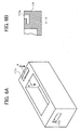
- FIG. 5 is a diagram of another example of a handhold provided to the printing unit;
- FIG. 6A is a perspective view of the printing unit in which grooves serving as handholds are provided;
- FIG. 6B is a cross section at an A-A line of FIG. 6A;
- FIG. 7A is a diagram illustrating an outer appearance of the copying apparatus according to another preferred embodiment of the present invention, viewed almost from the front side;
- FIG. 7B is a diagram illustrating a state of the copying apparatus of FIG. 7B when every cover that can be opened for clearing a jammed sheet has been opened;
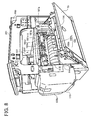
- FIG. 8 is a perspective view illustrating a state of the copying apparatus when a conveying path cover at the right side in the front view of the copying apparatus is opened;
- FIG. 9 is a perspective view of the copying apparatus in which a cover covering the front side of the printing unit and an ink tank cover are omitted;
- FIG. 10 is a perspective view illustrating a state of the copying apparatus in which the printing unit has been drawn out;
- FIG. 11 is a perspective view illustrating the state of the copying apparatus of FIG. 10, viewed from the front side of the copying apparatus;
- FIG. 12 is a schematic perspective view of the printing unit illustrating a state of a connector part thereof;
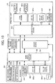
- FIG. 13 is a block diagram for explaining control of the copying apparatus;
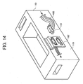
- FIG. 14 is a schematic perspective view of the printing unit illustrating another example of the connector part; and
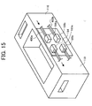
- FIG. 15 is a schematic perspective view of the printing unit illustrating another example of the connector part.
-
- Referring now to the drawings, wherein like reference numerals designate identical or corresponding parts throughout the several views, preferred embodiments of the present invention are described.
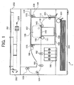
- FIG. 1 is a diagram schematically illustrating a construction of a copying apparatus 1 using an ink jet printing method as an image forming apparatus according to a preferred embodiment of the present invention, viewed from a direction perpendicular to a sheet conveying direction (i.e., the main scanning direction). The copying apparatus 1 includes an
image forming part 100, an image reading part (scanner) 200, and asheet feeding part 300. Theimage forming part 100 is arranged above thesheet feeding part 300, and theimage reading part 200 is arranged above theimage forming part 100. - Stacked recording sheets (recording media) are accommodated in the
sheet feeding part 300 and are fed one by one from the uppermost one toward theimage forming part 100 with a separation and conveyingpart 301 including a pick-up roller. - The
image reading part 200 is configured to read an original document placed on acontact glass 201 with a CCD (charge coupled device) 203 by moving a readingoptical system 202. - The
image forming part 100 includes conveyingrollers roller 104, a dischargingroller 105, aprinting unit 110, and anink tank 106. Theprinting unit 110 includes, as described later, aprinting mechanism part 120, a sub-scanning conveyingmechanism part 140, amaintenance mechanism part 150, and a blankprinting mechanism part 160. - In the copying apparatus 1 configured as described above, a recording sheet separated at the separating and conveying
part 301 of thesheet feeding part 300 is guided to theprinting unit 110 by the conveyingroller 101 through a portion of a conveyingpath 112 conveying the recording sheet to a dischargingtray 107 provided to an upper surface of ahousing 402 of theimage forming part 100. The recording sheet is conveyed by the sub-scanning conveying mechanism part 140 a predetermined conveying distance set according to a printing width of ink jet printing heads (described later) in the sub-scanning direction and a predetermined number of lines are printed on the recording sheet. By repeating this operation, image data obtained at theimage reading part 200 is printed on the recording sheet, thereby forming an image on the recording sheet. The recording sheet on which the image has been formed is conveyed with the conveyingrollers roller 104, where the recording sheet is reversed in the conveying direction. The recording sheet is then discharged with a dischargingroller 105 onto the dischargingtray 107. - As illustrated in FIG. 1, the
image reading part 200 is arranged above theimage forming part 100 sandwiching the dischargingtray 107 with theimage forming part 100, so that a space for replacing theprinting unit 110 cannot be obtained above theprinting unit 110. - FIG. 2 is a right side view of the copying apparatus 1 illustrated in FIG. 1, and FIG. 3 is a perspective view schematically illustrating an exemplary construction of the
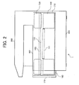
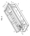
printing unit 110. Theprinting unit 110 is configured as a unit in which theprinting mechanism part 120, the sub-scanning conveyingmechanism part 140, themaintenance mechanism part 150, and the blankprinting mechanism part 160 are mounted, and a recording sheet conveying path 111 (a portion of the conveying path 112) is provided between theprinting mechanism part 120 and the sub-scanning conveyingmechanism part 140. - The
maintenance mechanism part 150 includes mechanical elements necessary for maintaining the operation capability of the ink jet printing heads, such as a cap configured to prevent a nozzle of the ink jet printing head from being dried, a wiper configured to wipe a nozzle surface of the ink jet printing head to remove ink from the nozzle surface, etc., and is arranged at the side of the home position of the ink jet printing head. The blankprinting mechanism part 160 is arranged at an end part at the opposite side of the home position of the ink jet printing heads in the main scanning direction to perform blank printing at the start of printing or at a predetermined timing to prevent ink clogging. The blankprinting mechanism part 160 includes at its bottom part a discharged ink receiver arranged to oppose the ink jet printing heads to receive discharged ink in blank printing. A known mechanism may be used for each of themaintenance mechanism part 150 and the blankprinting mechanism part 160, and therefore description thereof is omitted. - The
printing mechanism part 120 includes, as illustrated in FIG. 3, acarriage 121, a pair of guide members (not shown) guiding thecarriage 121 in the main scanning direction, and amain scanning motor 122 to move thecarriage 121 along the pair of guide members in the main scanning direction. Thecarriage 121 is provided with the ink jet printing heads having discharging outlets for a predetermined number of lines at the bottom surface thereof for each of yellow (Y), magenta (M), cyan (C) and black (K) colors. Ink is provided to thecarriage 121 from the ink tank 106 (illustrated in FIG. 1). Themain scanning motor 122 is arranged at the side of the blank printing mechanism 160 (i.e., at the front side in a later-described drawing direction in which theprinting unit 110 is drawn out) , and an output end of themain scanning motor 122 is connected with thecarriage 121 through the intermediary of a timing belt (not shown) so that rotation of themain scanning motor 122 is converted to a linear motion of thecarriage 121, and thereby thecarriage 121 is moved in the main scanning direction. One of the pair of guide members may be configured by a screw axis to be rotated by themain scanning motor 122. - The sub-scanning conveying
mechanism part 140 includes, as illustrated in FIG. 1,sub-scanning rollers 141, aplaten 142, and conveyingrollers 143. Thesub-scanning rollers 141 convey a recording sheet the predetermined conveying distance with a driving mechanism (not shown), and printing is performed with the ink jet printing heads mounted to thecarriage 121 opposing theplaten 142 and moving in the main scanning direction. Printing with the ink jet printing heads moving in the main scanning direction is performed each time the recording sheet is conveyed the predetermined conveying distance in the sub-scanning direction. Thecarriage 121 reciprocates in the main scanning direction, and printing is performed in each process of the reciprocating motion of the carriage 12i mounting the ink jet printing heads. - In the
printing unit 110 illustrated in FIG. 3, a conveyingbelt 144 is used in the sub-scanning conveyingmechanism part 140, and the dimension of a stretched portion of the conveyingbelt 144 in the conveying direction is set substantially the same as that of thecarriage 121 in the sub-scanning direction. This is because that the printing width (i.e., the number of dots simultaneously printed in the sub-scanning direction) of the ink jet printing heads mounted to thecarriage 121 is relatively large and it is necessary to maintain the flatness of the conveyingbelt 144 relative to the printing width. For maintaining the flatness of the conveyingbelt 144 relative to the printing width, an electrostatic belt that attracts the recording sheet with an electrostatic action or an attracting belt that attracts the recording sheet by making an air pressure on the belt to be negative may be used for the conveyingbelt 144. When the above-described configuration with thesub-scanning rollers 141 and theplaten 142 is used, it is necessary to obtain a desired flatness with theplaten 142. - The conveying
belt 144 moves in the sub-scanning direction by rotating abelt drive axis 146 with asub-scanning motor 145. Thesub-scanning motor 145 is attached to a surface of afront side plate 113 of theprinting unit 110 at the side of the blank printing mechanism part 160 (i.e., thefront side plate 113 at the front side in the drawing direction described later), and drives thebelt drive axis 146 through the intermediary of atiming belt 147. Further, the conveyingrollers 143 are arranged at the recording sheet carrying-in and carrying-out side ends of the recordingsheet conveying path 111 to oppose thesub-scanning rollers 141, and the recording sheet is conveyed from thesheet feeding part 300, via the separation and conveyingpart 301, the conveyingroller 101, and the conveyingpath 112, through thesub-scanning roller 141 and the conveyingroller 143 at the recording sheet carrying-in side to a printing area where printing is performed with the ink jet printing heads mounted to thecarriage 121 moving in the main scanning direction as described above. The conveyingroller 143 and thesub-scanning roller 141 at the recording sheet carrying-out side end of thesheet conveying path 111 may be omitted by extending the length of the stretched portion of the conveyingbelt 144 toward a downstream side of the recording sheet carrying-out side end of the conveyingpath 111 in the direction in which the recording sheet is conveyed. - The
printing unit 110 includes ahousing 119 having a substantially rectangular parallelepiped outer shape. The pair of guide members of thecarriage 121 and thebelt drive axis 146 are arranged between thefront side plate 113 and arear side plate 114, and theblank printing mechanism 160 and themaintenance mechanism part 150 are arranged inside of thefront side plate 113 and therear side plate 114, respectively. The conveyingrollers 143 are supported with bearings to idle by roller axes provided between thefront side plate 113 and therear side plate 114. A pair ofrails 115 extending along a direction perpendicular to the recording sheet conveying direction and protruding along the recording sheet conveying direction toward outside, respectively, are provided to upper edge parts of thehousing 119.Handholds housing 119 at the side of thefrond side plate 113 and therear side plate 114, respectively. - The
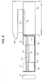
printing unit 110 configured as described above is drawn out from the front of theimage forming part 100 as illustrated in FIG. 4, and is detached from theimage forming part 100. An opening part is provided in the front surface of theimage forming part 100 so that theprinting unit 110 can be drawn out. Rail guides 109 (FIG. 1) are provided to theimage forming part 100 in the direction perpendicular to the recording sheet conveying direction to receive the pair ofrails 115 of theprinting unit 110. Further, a positioning mechanism (not shown) for theprinting unit 110 is provided to thehousing 402 of theimage forming part 100 at the position opposing therear side plate 114 of theprinting unit 110. When theprinting unit 110 is inserted into theimage forming part 100 toward the rear side of theimage forming part 100 along the rail guides 109, theprinting unit 110 is positioned by the positioning mechanism in a final process of inserting theprinting unit 110 into theimage forming part 100 and is locked there. When drawing out theprinting unit 110 from theimage forming unit 100, by grabbing thehandhold 116 at the side of thefront side plate 113 by one hand and pulling theprinting unit 110 in the direction in which theprinting unit 110 is drawn out, theprinting unit 110 is released from being locked, so that theprinting unit 110 can be drawn. After theprinting unit 110 has been drawn a predetermined (or maximum) distance to a position where thehandhold 117 at the side of therear side plate 114 can be grabbed, by grabbing thehandhold 117 with the other hand, theprinting unit 110 can be detached from theimage forming unit 100. To prevent theprinting unit 110 from being disengaged from the rail guides 109 before thehandhold 117 at the side of therear side plate 114 is grabbed, a stopper is provided. The stopper may be appropriately configured with the rail guides 109 and end parts of the pair ofrails 115 at the side of thehandhold 117 to temporarily regulate movement of theprinting unit 110. - By configuring the
printing unit 110 to be drawn out of theimage forming part 100 as described above, maintenance work of theprinting unit 110 can be performed in a state that theprinting unit 110 has been drawn out from theimage forming part 100. Therefore, it is not necessary to detach theimage reading part 200 and the dischargingtray 107 above theimage forming part 100 to perform the maintenance work of theprinting unit 110, so that efficiency of the maintenance work can be improved. Further, in theprinting unit 110 drawn out from theimage forming part 100, theprinting mechanism part 120, the sub-scanning conveyingmechanism part 140, themaintenance mechanism part 150, and the blankprinting mechanism part 160 are sufficiently exposed, respectively, so that workability is superior. - The
handhold 116 at the side of thefront side plate 113 is configured by a synthetic resin belt attached to a part of thefront side plate 113 with bolts, and thehandhold 117 at the side of therear side plate 114 is configured by a part of thehousing 119. - However, as illustrated in FIG. 5, each of the
handhold 116 and thehandhold 117 may be configured by a rigid member such as metal formed in a shape that the member can be grabbed with fingers, or as illustrated in FIG. 6A, thehousing 119 may be formed with a synthetic resin while integrally providinggrooves housing 119 at a A-A line of FIG. 6A, each of thegrooves printing unit 110 can be born by fingers inserted into thegrooves - Further, the
handhold 116 illustrated in FIG. 3 may be configured such that parts of the belt, that are pressed by the bolts, are formed in grooves, respectively, and when the belt is grabbed by fingers and is pulled to be moved, end parts of the grooves of the belt are hooked by head parts of the bolts and thereby the load of theprinting unit 110 is born. - In the above-described embodiment, the
printing unit 110 is drawn out using a sliding mechanism configured by the pair ofrails 115 and the rail guides 109. However, theprinting unit 110 may be drawn out using a guide rod and a sliding or rolling mechanism arranged along the guide rod. Further, the floor surface of theimage forming part 100 may be configured such that theprinting unit 110 can slide and move over the floor surface. Any other configuration may be appropriately used for drawing out theprinting unit 110 from theimage forming part 100 and pushing theprinting unit 110 into theimage forming part 100 to be set there. - A
cover 170 is provided to the opening part of the front surface of theimage forming part 100, through which theprinting unit 110 is drawn out. In the embodiment, thecover 170 is configured to cover the opening part, however, may be configured to cover the entire part of the front surface of theimage forming part 100. - By configuring the copying apparatus 1 as described above, when repair or replacement is necessary relative to any element of the
printing unit 110, instead of detaching the element from theprinting unit 110 for repairing at a repair shop, theprinting unit 100 itself can be easily replaced at the customer's premises, so that the copying apparatus 1 can be immediately put into a usable condition. Thereby, downtime can be kept at a minimum, so that user satisfaction can be increased. - Further, when detaching the
printing unit 110, by first closing an ink supplying path for supplying ink from theink tank 106 to thecarriage 121, ink leakage can be avoided. - In the embodiment, the
printing unit 110 as an integrated unit that can be drawn out is configured by theprinting mechanism part 120, the sub-scanning conveyingmechanism part 140, themaintenance mechanism part 150, and the blankprinting mechanism part 160. However, theprinting unit 110 may be configured, as an integrated unit that can be drawn out, by including at least theprinting mechanism part 120. In this case, a control circuit to perform control of moving thecarriage 121 in the main scanning direction may be also included in theprinting unit 110. Furthermore, theprinting unit 110 may be configured as an integrated unit that can be drawn out by including at least theprinting mechanism part 120 and the sub-scanning conveyingmechanism part 120. In this case also, the control circuit to perform control of moving thecarriage 121 in the main scanning direction and a control circuit performing control of conveying a recording medium in the sub-scanning direction may be included in theprinting unit 110 . - Further, in an optical writing line printer and a thermal transfer printer using an LED for the
printing mechanism part 120 of theprinting unit 110, themaintenance mechanism part 150 and the blankprinting mechanism part 160 used in an image forming apparatus using an ink jet printing head are not needed, so that only theprinting mechanism part 120 may be included in theprinting unit 110 configured as a unit that can be drawn out. In this case, theprinting unit 110 may be configured to include a sub-scanning conveying mechanism, and further a control circuit may be included. - As described above, in an image forming apparatus using an ink jet printing method, when detaching a printing unit from the main body of the apparatus, besides mechanical detachment of the printing unit from the main body of the apparatus, detachment of electrical systems connecting the printing unit. and the main body of the apparatus must be also considered. Herein below, another feature of the present invention concerning detachment of electrical systems connecting a printing unit and the main body in an image forming apparatus using an ink jet printing system is described. In the following description, parts identical or corresponding to those in the previous embodiment are designated with like reference numerals, and overlapping descriptions are omitted.
- FIG. 7A and FIG. 7B illustrate the copying apparatus 1 according to another preferred embodiment of the present invention, in which detachment of electrical systems connecting the
printing unit 110 and the main body and clearance of jammed sheets have been considered. FIG. 7A illustrate an outer appearance of the copying apparatus 1 viewed almost from the front side, and FIG. 7B illustrates a state of the copying apparatus 1 when every cover that can be opened for clearing a jammed sheet has been opened. - In the copying apparatus 1, the
cover 170 covering the front part of theprinting unit 110 accommodated in the copying apparatus 1 by covering the opening part of the front surface of theimage forming part 100 as described above is configured to open. Further, as illustrated in FIG. 7B, first and second conveying path covers 1a and 1b as side covers of the copying apparatus 1 are configured to open to expose portions of the conveyingpath 112, anink tank cover 106a covering the front side of theink tank 106 is configured to open, a third conveying path cover 112a covering a portion of the conveyingpath 112 above theink tank 106 is configured to open, and a fourth conveyingpath 142a covering theplaten 142 is configured to open. Upper surfaces of the third conveying path cover 112a and the fourth conveying path cover 142a function as the dischargingtray 107, and therefore a sheet surface detectsensor 107a (FIG. 11) is provided above the third conveying path cover 112a. In FIG. 7A, anADF 210 mounted above thecontact glass 201 is illustrated. - FIG. 8 illustrates a state of the copying apparatus 1 when the second conveying path cover 1b (at the right side in the front view of the copying apparatus 1) is opened, FIG. 9 is a perspective view of the copying apparatus 1 in which the
cover 170 and theink tank cover 106a are omitted, FIG. 10 is a perspective view illustrating a state of the copying apparatus 1 in which theprinting unit 110 has been drawn out, and FIG. 11 is a perspective view illustrating the state of the copying apparatus 1 of FIG. 10, viewed from the front side of the copying apparatus 1. As illustrated in FIGs. 8, 9 and 10, aconnector part 180 configured by afirst connector board 180a and asecond connector board 180b is arranged at an upper part of a side surface of thehousing 119 of theprinting unit 110, that opposes the first conveying path cover 1b when theprinting unit 110 is accommodated in the main body of the copying apparatus 1. Thereby, when the first conveying path cover 1 is opened, theconnector part 180 is exposed. Respective parts of theprinting unit 110 and a main body control board 190 (FIG. 10) at the side of the main body of the copying apparatus 1 are connected with each other through the intermediary of theconnector part 180. In this embodiment, the connection function of theconnector part 180 is divided between thefirst connector board 180a and thesecond connector board 180b. Thefirst connector board 180a and thesecond connector board 180b are provided to the side surface of thehousing 119 of theprinter unit 110 as illustrated in FIG. 12, so as to be parallel to a side surface of the copying apparatus 1.Symbol 144a denotes a conveying guide plate arranged around a periphery of the conveying belt 144 (see FIG. 3) so that the conveyingbelt 144 will not be exposed when the first conveyingpath cover 1b has been opened. Further, as illustrated in FIG. 11, anencoder system 144b is provided to the front surface of theprinting unit 110 to detect a rotation amount of the sub-scanning motor 145 (see also FIG. 3) driving the conveyingbelt 144. Theencoder system 144b is configured to detect a conveying distance of a recording sheet in the sub-scanning direction by counting the number of pulses of an encoder, which is rotated by a driving force of arotation axis 145a of thesub-scanning motor 145, with an encoder sensor (not shown), and converting the number of pulses into a rotation amount. - As illustrated in FIG. 12 illustrating a state of the
connector part 180, at the side of thefirst connector board 180a arranged are aconnector 181a for connection with the mainbody control board 190,connectors printing unit 110, such as the printing heads mounted to thecarriage 121 of theprinting mechanism part 120, themaintenance mechanism part 150, and the blankprinting mechanism part 160, and aconnector 181e for connection with thesecond connector board 180b. Wiring patterns are formed at the back surface of thefirst connector board 180a to connect theconnector 181a with theconnector 181b, theconnector 181c, theconnector 181d and theconnector 181e. By connecting aconnector 191 at a tip end ofsignal lines 400 from the mainbody control board 190 with theconnector 181a, connection of the mainbody control board 190 and respective parts of theprinting unit 110 is realized through the intermediary of the wiring patterns and theconnectors cables printing unit 110. Theconnector 181a, theconnector 181b, theconnector 181c, theconnector 181d and theconnector 181e are arranged such that respective connecting cables do not cross each other and thereby noise will not be picked up. Thesecond connector board 180b is connected with the first connector board 1980a via theconnector 181e and is configured such that signals for controlling the sub-scanning conveyingmechanism part 140 and theprinting mechanism part 120 are inputted and outputted via aconnector 181f. - In FIG. 12, the
connector part 180, i.e., thefirst connector board 180a and thesecond connector board 180b, are arranged substantially along the entire portion of the side surface of theprinting unit 110 in the longitudinal direction, however, thefirst connector board 180a and thesecond connector board 180b are actually arranged at positions closer to therear side plate 114 of theprinting unit 110 as illustrated in FIG. 8 such that lengths of the connectingcables connector 181a is arranged in thefirst connector board 180a at a position closest to therear side plate 114. Here, the mainbody control board 190 is arranged at a rear part in the main body of the copying apparatus 1 and at the side of the first conveying path cover 1b, so that lengths of the connectingcables 400 of theconnector 191 of the mainbody control board 190 are made relatively short. Further, as described above, theconnector part 180 configured by thefirst connector board 180a and thesecond connector board 180b is provided to the side surface of theprinting unit 110 opposing the second conveying path cover 1b when theprinting unit 110 is accommodated in the main body of the copying apparatus 1, so that theconnector part 180 is exposed by opening the second conveying path cover 1b. Thus, by opening the second conveying path cover 1b and by detaching theconnector 191 of the mainbody control board 190 from theconnector 181a of thefirst connector board 180a, electrical connection between theprinting unit 110 and the mainbody control board 190 is disconnected, and thereby theprinting unit 110 can be detached from the main body of the copying apparatus 1. Further, because the lengths of the connectingcables 400 extending from themain control board 190 of the main body are made relatively short as described above, when detaching theprinting unit 110 from the main body of the copying apparatus 1, the connectingcables 400 will not be obstructive. - FIG. 13 is a block diagram for explaining control of the copying apparatus 1. In the copying apparatus 1 illustrated in FIG. 8 through FIG. 12, the
connector part 180 configured by two boards, i.e., thefirst connector board 180a and thesecond connector board 180b, is used. However, theconnector part 180 may be configured by a single board, and in FIG. 13, aconnector board 197a as an example of theconnector part 180 configured by a single board is used for theconnector part 180. - The main
body control board 190 includes a control part including a CPU, a ROM and a RAM, a driver for driving drive parts such as a pump, a motor, etc., and other control elements used for the control. Theimage reading part 200 includes an SBU (scanner board unit) 200a including a CCD and an SBU ASIC, alighting device 200b, and a set ofsensors 200c including a HP (home position) sensor, an APS sensor, and an original platen open/close sensor. Inputting and outputting of detect signals and control signals are performed between theimage reading part 200 and the mainbody control board 190. A CTL (controller)board 192 is provided with a GWS ASIC and is configured to perform control of displaying and control of inputting and outputting at an operation and display part of the copying apparatus 1. TheCTL board 192 outputs and inputs signals to and from the mainbody control board 190. - The
sheet feed part 300 includes a set ofsensors 300a and a set ofdrive parts 300b for sheet feeding. The mainbody control board 190 receives detect signals from the set ofsensors 300a and sends drive signals to the set ofdrive parts 300b. The set ofsensors 300a includes, for example, a registration sensor, a relaying sensor, a size detect sensor, a sheet existence detect sensor, a cover open/close sensor, etc. The set ofdrive parts 300b includes motors, solenoids and clutches for driving the conveyingrollers roller 105, thesub-scanning rollers 141, and the feeding roller of the separation and conveyingpart 301. - A PSU (power source unit) 193 supplies power to respective parts of the copying apparatus 1. A
driver board 194 includes piezoelectric thermistors, and is configured to control discharging of ink at the ink jet printing heads for respective colors mounted to thecarriage 121 of theprinting unit 110. Thedriver board 194 is connected with the mainbody control board 190 and theprinting unit 110. The mainbody control board 190 is also connected with anSD card board 195 and an OPU (optional unit)board 196. TheSD card board 195 enables updating of a program and installing of a new program using an SD card, and theOPU board 196 enables connection of an optional unit. - The
printing unit 110 includes theconnector board 197a as an example of theconnector part 180 configured by a single board, and a COM (common)board 197b connected withprinting heads 197d for respective colors (i.e., the ink jet printing heads mounted to the carriage 121) and a set ofsensors 197c concerning the printing heads 197d. Theprinting unit 110 further includes a set ofsensors 197e concerning other parts than the printing heads 197d, a set ofdrive parts 197f including clutches, solenoids, etc., and amain scanning encoder 188. In this embodiment, printing heads for 5 colors are provided, so that five units of the set of thesensors 197e and the set ofdrive parts 197f are provided, respectively. The set ofsensors 197c concerning the printing heads 197d includes, for example, a head environmental temperature sensor, an image registration sensor, and an air detect sensor. The set ofsensors 197e concerning parts other than the printing heads 197d includes a rotary encoder sensor for the sub-scanning direction, a carriage rising sensor, and an ink cartridge existence detect sensor. The set ofdrive parts 197f includes a sheet counter, various types of clutches, and a motor. - As described above, the
connector board 197a corresponds to theconnector part 180 in this embodiment, and through the intermediary of theconnector board 197a, the mainbody control board 190 and thedriver board 194 at the side of the main body of the copying apparatus 1 are connected with theCOM board 197b, the sets ofsensors 197e, the sets ofdrive parts 197e, etc. of theprinting unit 110. TheCOM board 197b and theconnector board 197a are connected with 75 signal lines, the sets ofsensors 197e and theconnector board 197a are connected with 55 signal lines, the sets ofdrive parts 197f and theconnector board 197a are connected with 32 signal lines, and themain scanning encoder 188 and theconnector board 197a are connected with 6 signal lines, although a heavy or outline arrow line is used in illustrating each connection in FIG. 13. Thus, the signal lines of theconnector board 197a almost amount to 170, and if signal lines for communicating with themaintenance mechanism part 150 and the blankprinting mechanism part 160 are added, the signal lines of theconnector board 197a amount to about 200. Therefore, a plurality of connectors are provided on theconnector board 197a, i.e., theconnector 181a for connection with the mainbody control board 190, and theconnectors printing unit 110, that are provided, in FIG. 12, to thefirst connector boat 180a, and theconnector 181f connecting with the sub-scanning conveyingmechanism part 140 and theprinting mechanism part 120, that is arranged, in FIG. 12, for connection with thesecond connector board 180b, and wiring patterns are formed at the back surface of theconnector board 197a to connect theconnector 181a with theconnectors connector 191 at the tip ends of thesignal lines 400 from the mainbody control board 190 with theconnector 181a as in FIG. 12, connection of the mainbody control board 190 with theCOM board 197b, the sets ofsensors 197e, the sets ofdrive parts 197f, and themain scanning encoder 188, etc. , is realized, so that connection of the mainbody control board 190 with respective parts of theprinting unit 110 is realized. Thus, when drawing out theprinting unit 110 from the main body of the copying apparatus 1, by detaching theconnector 191 from theconnector 181a, connection between the mainbody control board 190 and theprinting unit 110 is broken electrically and physically, so that theprinting unit 110 can be drawn out of the main body of the copying apparatus 1. - When the
connector part 180 is configured by thefirst connector board 180a and thesecond connector board 180b and theconnector 181f is provided for connection with thesecond connector board 180b, the signals for controlling the sub-scanning conveyingmechanism 140 and theprinting mechanism part 120 are inputted to and outputted from thesecond connector board 180b via theconnector 181f as described above. Therefore, the sub-scanning conveyingmechanism part 140 and theprinting mechanism part 120 can be replaced independently from other parts by detaching theconnector 181f, respectively. - Further, it is needless to say that the
connector part 180 can be configured with three or more boards. - In this embodiment, the
handhold 117b at the rear side of theprinting unit 110 is configured with a belt and thehandhold 116b at this side (the front side) is configured by a concave part provided at the bottom part of the front side of theprinting unit 110 as illustrated in FIG. 11. When theprinting unit 110 is set in the main body of the copying apparatus 1, thehandhold 117b at the rear side retreats along the upper surface of a frame extending in a direction perpendicular to the sheet conveying direction with a tip end thereof fastened with apin 117c. When drawing out theprinting unit 110, the tip end of thehandhold 117b is disengaged from thepin 117c and thehandhold 117b is bent in the direction perpendicular to the frame as indicated by a dashed line in FIG. 11 and the tip end thereof is fixed to a fixingclasp 117d so that thehandhold 117b can be grasped by fingers. By grasping thehandhold 117b at the rear side, which is configured with the belt, and thehandhold 116b at the front side, which is configured by the concave part, as described above, theprinting unit 110 can be easily lifted. Accordingly, after drawing out theprinting unit 110 to a predetermined position, theprinting unit 110 can be easily detached from the main body of the copying apparatus 1. - In this embodiment, the
ink tank 106 is integrated with theprinting unit 110, as illustrated in FIG. 11, at a left side front part (when the copying apparatus 1 is viewed from the front side) of theprinting unit 110. For example, theink tank 106 may be integrated with theprinting unit 110 by screwing a member (not shown) extending from theink tank 106 toward theprinting unit 110 on theprinting unit 110. Accordingly, when theprinting unit 110 is drawn and is detached from the main body of the copying apparatus 1, theink tank 106 is drawn integrally with theprinting unit 110 to be detached from the main body of the copying apparatus 1, so that it is not necessary to detach an ink supply path (not shown) , which supplies ink from theink tank 106 to the printing heads of theprinting unit 110, from theprinting unit 110. Thereby, there is no possibility that ink leaks from the ink supply path when detaching theprinting unit 110 from the main body of the copying apparatus 1, so that theprinting unit 110 can be easily detached. - In this embodiment, differently from the previous embodiment, the
printing unit 110 is supported at alower rail 115a by arail guide 109a of the main body of the copying apparatus 1 to be drawn out, as illustrated in FIG. 9 and FIG. 10. Thereby, an upper rail guide (the rail guides 109) in the previous embodiment is not necessary, so that freedom in a space above theprinting unit 110 is increased and a relatively large working space can be secured. When clearing a jammed sheet, as illustrated in FIG. 7B, thecover 112a above the conveyingpath 112 and thecover 142a covering theplaten 142 are opened. In this case, in the previous embodiment, there is a possibility that the rail guides 109 interfere with clearing of a jammed sheet. However, in this embodiment, as illustrated in FIG. 11, because no element exists in the apace above theprinting unit 110, clearing of a jammed sheet is relatively easy. - In this embodiment, the
connector part 180 is configured by theconnector board 197a as in FIG. 13 or by the first andsecond connector boards connector part 180 may be configured, as illustrated in FIG. 14, by apanel mount 182 having a plurality of connecting terminals connected with respective parts of theprinting unit 110. In this case, for example, aconnector 183 connected withsignal lines 400 from the mainboard control board 190 is connected with each of the plurality of terminals of thepanel mount 182. The positions and the numbers of pins of the connecting terminals of thepanel mount 182 and theconnectors 183 may be set to correspond to each other to avoid erroneous connection. As necessary, plural units of thepanel mount 182 may be provided. - Further, as illustrated in FIG. 15, the
connector part 180 may be configured by a printedcircuit board 184 provided to a side surface of theprinting unit 110, and a plurality of connectors divided by functions, arranged on theprinting circuit board 184 and connecting with respective parts of theprinting unit 110. In this example, aconnector 185a and aconnector 185b are provided on the printedcircuit board 184. A plurality of connectors, in this example, aconnector 186a and aconnector 186b, provided at tip ends ofsignal lines body control board 190, are connected to theconnector 185a and theconnector 185b. In this case also, the positions and the numbers of pins of the connectors on theprinting circuit board 184 and the connectors at the tip ends of signal lines from the mainbody control board 190 may be set to correspond to each other to avoid erroneous connection. - In the above-described embodiments, the copying apparatus 1 including the
image reading part 200 arranged above theimage forming part 100 has been used as an example of the image forming apparatus of the present invention. However, it is needless to say that the present invention can be applied to a printer in which an image reading part is not included. - Numerous additional modifications and variations of the present invention are possible in light of the above teachings. It is therefore to be understood that within the scope of the appended claims, the present invention can be practiced otherwise that as specifically described herein.
Claims (45)
- An image forming apparatus comprising:a printing part configured to form an image on a recording medium; anda guide device configured to guide the printing unit to be drawn in a direction perpendicular to a recording medium conveying direction in which the recording medium is conveyed.
- The image forming apparatus according to claim 1, wherein the guide device includes a guide member provided to a main body of the apparatus and extending in the direction perpendicular to the recording medium conveying direction, and a guided member provided to the printing part and configured to be guided by the guide member.
- The image forming apparatus according to claim 2, wherein the guided member provided to the printing part includes a protruding member, and the guide member provided to the main body supports the protruding member so as to be movable in the direction perpendicular to the recording medium conveying direction.
- The image forming apparatus according to claim 1, wherein the guide device includes a floor surface of an accommodating part of a main body of the apparatus accommodating the printing part.
- The image forming apparatus according to claim 1, wherein the guide device supports the printing part so as to be detachable from the main body.
- The image forming apparatus according to claim 1, wherein the printing part includes a printing mechanism including a carriage mounting an ink jet printing head and configured to move the carriage in a main scanning direction.
- The image forming apparatus according to claim 6, wherein the printing part includes a maintenance mechanism configured to maintain a writing function of the ink jet printing head.
- The image forming apparatus according to claim 6, wherein the printing mechanism includes a control circuit to perform control of moving the carriage in the main scanning direction.
- The image forming apparatus according to claim 6, wherein the printing unit includes a connection device arranged at a part of the printing part, that is exposed when, in a state that the printing part is accommodated in the main body of the apparatus, a side cover of the apparatus has been opened and configured to connect the printing mechanism of the printing part with a control part of the main body of the apparatus.
- The image forming apparatus according to claim 9, wherein the connection device includes a board fixed to the printing part and a first connector arranged on the board to connect with the control part of the main body of the apparatus.
- The image forming apparatus according to claim 10, wherein the connection device further includes a second connector arranged on the board and connecting with the printing mechanism of the printing part, and a wiring pattern formed on the board to connect the second connector and the first connector.
- The image forming apparatus according to claim 9, wherein the connection device includes a board fixed to the printing part, and a connector arranged on the board and configured to connect the printing mechanism of the printing part and a control part of the main body of the apparatus.
- The image forming apparatus according to claim 6, wherein the printing part includes a sub-scanning conveying mechanism to convey the recording medium in a sub-scanning direction at a part of the printing part where the image is formed on the recording medium
- The image forming apparatus according to claim 13, wherein the sub-scanning conveying mechanism includes a conveying roller, a platen, and a drive source driving the conveying roller.
- The image forming apparatus according to claim 13, wherein the sub-scanning conveying mechanism includes a conveying roller, a conveying belt, and a drive source driving at least either of the conveying roller and the conveying belt.
- The image forming apparatus according to claim 15, wherein the conveying belt is an electrostatic belt.
- The image forming apparatus according to claim 13, wherein the sub-scanning conveying mechanism includes a control circuit to perform control of conveying the recording medium in the sub-scanning direction.
- The image forming apparatus according to claim 13, wherein the printing part includes a connection device arranged at a part of the printing part, that is exposed when, in a state that the printing part is accommodated in the main body of the apparatus, a side cover of the apparatus has been opened and configured to connect at least one of the printing mechanism and the sub-scanning conveying mechanism of the printing part with a control part of the main body of the apparatus.
- The image forming apparatus according to claim 18, wherein the connection device includes a board fixed to the printing part, and a first connector arranged on the board to connect with the control part of the main body of the apparatus.
- The image forming apparatus according to claim 19, wherein the connection device includes a second connector arranged on the board and connecting with at least one of the printing mechanism and the sub-scanning conveying mechanism of the printing part and a wiring pattern arranged on the board to connect the second connector and the first connector.
- The image forming apparatus according to claim 13, wherein the connection device includes a board fixed to the printing part, and a connector arranged on the board and configured to connect at least one of the printing mechanism and the sub-scanning conveying mechanism of the printing part with a control part of the main body of the apparatus.
- The image forming apparatus according to claim 1, wherein the printing part includes a sub-scanning conveying mechanism to convey the recording medium in a sub-scanning direction at a part of the printing part where the image is formed on the recording medium.
- The image forming apparatus according to claim 22, wherein the sub-scanning conveying mechanism includes a conveying roller, a platen, and a drive source driving the conveying roller.
- The image forming apparatus according to claim 22, wherein the sub-scanning conveying mechanism includes a conveying roller, a conveying belt, and a drive source driving at least either of the conveying roller and the conveying belt.
- The image forming apparatus according to claim 24, wherein the conveying belt is an electrostatic belt.
- The image forming apparatus according to claim 22, wherein the sub-scanning conveying mechanism includes a control circuit to perform control of conveying the recording medium in the sub-scanning direction.
- The image forming apparatus according to claim 22, wherein the printing part includes a connection device arranged at a part of the printing part, that is exposed when, in a state that the printing part is accommodated in the main body of the apparatus, a side cover of the apparatus has been opened and configured to connect the sub-scanning conveying mechanism of the printing part and a control part of the main body of the apparatus.
- The image forming apparatus according to claim 27, wherein the connection device includes a board fixed to the printing part and a first connector arranged on the board to connect with the control part of the main body of the apparatus.
- The image forming apparatus according to claim 28, wherein the connection device includes a second connector arranged on the board and connecting with the sub-scanning conveying mechanism of the printing part and a wiring pattern arranged on the board to connect the second connector and the first connector.
- The image forming apparatus according to claim 27, wherein the connection device includes a board fixed to the printing part, and a connector arranged on the board and configured to connect the sub-scanning conveying mechanism and the control part of the main body of the apparatus.
- The image forming apparatus according to claim 1, further comprising an ink tank configured to supply ink to the printing part and to be drawn integrally with the printing part when the printing part is drawn.
- The image forming apparatus according to claim 1, wherein the printing part includes a handhold.
- The image forming apparatus according to claim 32, wherein the handhold includes a belt-like member extending along a member of the printing part with a tip end thereof detachably fastened to the member and configured such that the tip end thereof can be detached from the member and after the tip end thereof has been detached from the member and the belt-like member has been bent, can be fastened to another member of the printing part so that the belt-like member can be grasped with fingers.
- The image forming apparatus according to claim 1, further comprising:wherein the image reading part is provided above the image forming part integrally with the image forming part.an image reading part configured to optically read an original document and to convert image information of the original document to an electrical signal; andan image forming part including the printing part,
- The image forming apparatus according to claim 34, wherein a discharging tray onto which the recording medium on which the image has been formed is discharged is provided between the image reading part and the image forming part.
- An image forming apparatus, comprising:a printing part detachable from a main body of the apparatus and configured to form an image on a recording medium; anda connection device arranged at a part of the printing part, that is exposed when, in a state that the printing part is accommodated in the main body of the apparatus, a side cover of the apparatus has been opened and configured to connect the printing part with a control part of the main body of the apparatus.
- The image forming apparatus according to claim 36, wherein the connection device includes a board fixed to the printing part, and a first connector arranged on the board and configured to connect with the control part of the main body of the apparatus.
- The image forming apparatus according to claim 37,
wherein the printing part includes a printing mechanism including a carriage mounting an ink jet printing head and configured to move the carriage in a main scanning direction, and a sub-scanning conveying mechanism to convey the recording medium in a sub-scanning direction at a part of the printing part where the image is formed on the recording medium, and
wherein the connection device further includes a second connector arranged on the board and connecting with at least one of the printing mechanism and the sub-scanning conveying mechanism of the printing part and a wiring pattern arranged on the board to connect the second connector and the first connector. - The image forming apparatus according to claim 38, wherein the first connector is arranged in the board fixed to the printing part at a rear side in a direction in which the printing part is drawn out.
- The image forming apparatus according to claim 36,
wherein the printing part includes a printing mechanism including a carriage mounting an ink jet printing head and configured to move the carriage in a main scanning direction, and a sub-scanning conveying mechanism to convey the recording medium in a sub-scanning direction at a part of the printing part where the image is formed on the recording medium, and
wherein the connection device includes a board fixed to the printing part, and a connector arranged on the board and configured to connect at least one of the printing mechanism and the sub-scanning conveying mechanism of the printing part with a control part of the main body of the apparatus. - The image forming apparatus according to claim 36, wherein the control part of the main body of the apparatus is arranged in the main body at a rear part thereof and at a side of the side cover of the apparatus.
- The image forming apparatus according to claim 36, wherein the connection device is arranged at a rear side in a direction the printing part is drawn out, in the part of the printing part, that is exposed when, in a state that the printing part is accommodated in the main body of the apparatus, the side cover of the apparatus has been opened.
- An image forming apparatus comprising:means for forming an image on a recording medium; andmeans for guiding the image forming means to be drawn in a direction perpendicular to a recording medium conveying direction in which the recording medium is conveyed.
- An image forming apparatus, comprising:means for forming an image on a recording medium, the image forming means being detachable from a main body of the apparatus; andmeans for electrically connecting the image forming means with a control part of the main body of the apparatus, the connecting means being arranged at a part of the image forming means, that is exposed when, in a state that the image forming means is accommodated in the main body of the apparatus, a side cover of the apparatus has been opened.
- A method of detaching a printing part in an image forming apparatus, comprising:opening a side cover of the apparatus to expose a part of the printing part accommodated in a main body of the apparatus;disconnecting a connector arranged at the part of the printing part to connect the printing part and a control part of the main body of the apparatus; anddrawing the printing part in a direction perpendicular to a direction in which a recording medium is conveyed to be detached from the main body of the apparatus.
Applications Claiming Priority (4)
| Application Number | Priority Date | Filing Date | Title |
|---|---|---|---|
| JP2003328769 | 2003-09-19 | ||
| JP2003328769 | 2003-09-19 | ||
| JP2004261326 | 2004-09-08 | ||
| JP2004261326A JP4473079B2 (en) | 2003-09-19 | 2004-09-08 | Image forming apparatus |
Publications (4)
| Publication Number | Publication Date |
|---|---|
| EP1520720A2 true EP1520720A2 (en) | 2005-04-06 |
| EP1520720A8 EP1520720A8 (en) | 2005-06-29 |
| EP1520720A3 EP1520720A3 (en) | 2005-07-20 |
| EP1520720B1 EP1520720B1 (en) | 2007-11-07 |
Family
ID=34315691
Family Applications (1)
| Application Number | Title | Priority Date | Filing Date |
|---|---|---|---|
| EP04022285A Expired - Fee Related EP1520720B1 (en) | 2003-09-19 | 2004-09-20 | Image forming apparatus |
Country Status (8)
| Country | Link |
|---|---|
| US (2) | US7445330B2 (en) |
| EP (1) | EP1520720B1 (en) |
| JP (1) | JP4473079B2 (en) |
| KR (1) | KR100692238B1 (en) |
| CN (1) | CN100346984C (en) |
| DE (1) | DE602004009876T2 (en) |
| ES (1) | ES2295750T3 (en) |
| HK (1) | HK1073631A1 (en) |
Cited By (1)
| Publication number | Priority date | Publication date | Assignee | Title |
|---|---|---|---|---|
| EP2065205B1 (en) * | 2007-11-30 | 2012-01-11 | Brother Kogyo Kabushiki Kaisha | Image recording apparatus |
Families Citing this family (24)
| Publication number | Priority date | Publication date | Assignee | Title |
|---|---|---|---|---|
| US7506948B2 (en) * | 2004-08-18 | 2009-03-24 | Ricoh Company, Ltd. | Image formation apparatus |
| JP4610369B2 (en) * | 2005-02-24 | 2011-01-12 | 株式会社リコー | Image forming apparatus |
| JP4551796B2 (en) | 2005-03-18 | 2010-09-29 | 株式会社リコー | Image forming apparatus |
| JP4597823B2 (en) * | 2005-09-14 | 2010-12-15 | 株式会社リコー | Image forming apparatus |
| JP4679316B2 (en) * | 2005-09-16 | 2011-04-27 | 株式会社リコー | Image forming apparatus |
| JP4680050B2 (en) * | 2005-10-04 | 2011-05-11 | 株式会社リコー | Image forming apparatus |
| JP4738997B2 (en) * | 2005-12-01 | 2011-08-03 | 株式会社リコー | Image forming apparatus |
| US7731352B2 (en) * | 2005-12-21 | 2010-06-08 | Ricoh Company, Ltd. | Image forming apparatus capable of allowing easy maintenance |
| JP4525620B2 (en) * | 2006-03-07 | 2010-08-18 | ブラザー工業株式会社 | Image recording device, multi-function device |
| US7658331B1 (en) * | 2006-06-15 | 2010-02-09 | Ncr Corporation | Checkout device with hand grip |
| JP5037180B2 (en) * | 2007-03-06 | 2012-09-26 | 株式会社リコー | Image forming apparatus |
| JP4975492B2 (en) * | 2007-03-19 | 2012-07-11 | 株式会社リコー | Image forming apparatus |
| JP4939377B2 (en) * | 2007-11-14 | 2012-05-23 | 株式会社リコー | Image forming apparatus |
| JP5004771B2 (en) | 2007-11-22 | 2012-08-22 | 株式会社リコー | Image forming apparatus |
| JP5233595B2 (en) | 2008-10-31 | 2013-07-10 | 株式会社リコー | Image forming apparatus and image forming apparatus assembly system |
| JP4968356B2 (en) * | 2010-03-31 | 2012-07-04 | ブラザー工業株式会社 | Recording device |
| JP5817111B2 (en) | 2010-12-15 | 2015-11-18 | 株式会社リコー | Opening / closing mechanism and image forming apparatus |
| US8833929B2 (en) * | 2011-08-11 | 2014-09-16 | Ricoh Company, Ltd. | Image forming apparatus |
| CN105172391B (en) * | 2014-06-12 | 2017-08-25 | 精工爱普生株式会社 | Tape deck |
| TWI552885B (en) * | 2014-09-01 | 2016-10-11 | 佳世達科技股份有限公司 | Printer |
| CN104325639A (en) * | 2014-09-09 | 2015-02-04 | 苏州佳世达光电有限公司 | Printer |
| JP6627329B2 (en) * | 2014-11-25 | 2020-01-08 | セイコーエプソン株式会社 | Recording device |
| JP6492882B2 (en) * | 2015-03-31 | 2019-04-03 | ブラザー工業株式会社 | Recording device |
| JP7447445B2 (en) | 2019-11-27 | 2024-03-12 | セイコーエプソン株式会社 | liquid discharge device |
Citations (9)
| Publication number | Priority date | Publication date | Assignee | Title |
|---|---|---|---|---|
| US3750794A (en) * | 1970-12-01 | 1973-08-07 | Burroughs Corp | High speed print drum with traveling print hammer |
| US4473312A (en) * | 1982-12-06 | 1984-09-25 | Ncr Corporation | Fastening mechanism for removably fastening together two workpieces |
| US4708502A (en) * | 1985-03-26 | 1987-11-24 | Seiko Espon Kabushiki Kaisha | Mounting mechanism for a print head |
| EP0372997A2 (en) * | 1988-12-08 | 1990-06-13 | Ncr International Inc. | Static dissipation in a printer |
| US5096316A (en) * | 1988-11-18 | 1992-03-17 | Seikosha Co., Ltd. | Serial printer |
| EP0765761A1 (en) * | 1995-09-29 | 1997-04-02 | Anritsu Corporation | Thermal printing apparatus |
| US5971525A (en) * | 1993-09-08 | 1999-10-26 | Canon Kabushiki Kaisha | Recording apparatus having a deelectrifying member for a recording head |
| US6153832A (en) * | 1999-02-08 | 2000-11-28 | Hewlett-Packard Company | Z-fold printhead carriage trailing cable for optimized panelization |
| US6406118B1 (en) * | 1988-12-30 | 2002-06-18 | Canon Kabushiki Kaisha | Ink jet recording apparatus having a heat fixing mechanism |
Family Cites Families (33)
| Publication number | Priority date | Publication date | Assignee | Title |
|---|---|---|---|---|
| US4708486A (en) * | 1985-05-20 | 1987-11-24 | Kabushiki Kaisha Toshiba | Image-forming apparatus |
| US5270738A (en) * | 1988-11-15 | 1993-12-14 | Canon Kabushiki Kaisha | Liquid jet recording apparatus having rotary transmitting member for recording medium |
| JP2810701B2 (en) | 1989-05-31 | 1998-10-15 | キヤノン株式会社 | Ink jet recording head and ink jet recording apparatus |
| JP2801409B2 (en) * | 1989-12-26 | 1998-09-21 | キヤノン株式会社 | Inkjet device and recording unit cartridge |
| JP2884544B2 (en) | 1991-12-04 | 1999-04-19 | キヤノン株式会社 | Recording device |
| JP3167486B2 (en) | 1993-02-09 | 2001-05-21 | シチズン時計株式会社 | Ink jet recording device |
| JPH06297722A (en) | 1993-04-19 | 1994-10-25 | Canon Inc | Cap and ink jet recording apparatus using the same |
| JP3467061B2 (en) * | 1993-06-25 | 2003-11-17 | 株式会社リコー | Operation unit and image forming apparatus |
| JP3319819B2 (en) * | 1993-06-25 | 2002-09-03 | 株式会社リコー | Image forming device management system |
| JPH0758903A (en) * | 1993-08-12 | 1995-03-03 | Ricoh Co Ltd | Automatic original carrier device |
| JP3378327B2 (en) * | 1993-12-28 | 2003-02-17 | 株式会社リコー | Sheet separation device |
| JP3379865B2 (en) * | 1994-12-19 | 2003-02-24 | 株式会社リコー | Image reading device |
| US5884860A (en) * | 1996-03-19 | 1999-03-23 | Ricoh Company, Ltd. | Rolled paper feeding apparatus which provides a constant torque for uncurling paper and a torque limiting device therefor |
| JP3490213B2 (en) * | 1996-04-11 | 2004-01-26 | 株式会社リコー | Paper transport device |
| JP3537981B2 (en) * | 1996-04-11 | 2004-06-14 | 株式会社リコー | Image forming device |
| US6128107A (en) * | 1996-04-12 | 2000-10-03 | Ricoh Company, Ltd. | Image apparatus having different motors for separating and reading documents |
| US6005687A (en) * | 1996-04-12 | 1999-12-21 | Ricoh Company, Ltd. | Imaging apparatus having different motors for separating and reading documents |
| US5961226A (en) * | 1996-08-16 | 1999-10-05 | Ricoh Company, Ltd. | Printing apparatus |
| JPH10112771A (en) * | 1996-10-04 | 1998-04-28 | Ricoh Co Ltd | Image reader |
| JP3495559B2 (en) * | 1996-11-05 | 2004-02-09 | 株式会社リコー | Automatic paper feeder |
| KR100307467B1 (en) * | 1997-03-27 | 2001-11-17 | 이토가 미찌야 | Sheet feeding apparatus with skew correction for fed sheets |
| JPH1198312A (en) * | 1997-04-18 | 1999-04-09 | Ricoh Co Ltd | Paper ejecting device |
| JP3347641B2 (en) * | 1997-05-20 | 2002-11-20 | キヤノン株式会社 | Interface device, information processing system, and control method of interface device |
| JPH11147650A (en) * | 1997-09-04 | 1999-06-02 | Ricoh Co Ltd | Recording paper stacker device |
| JPH11218980A (en) | 1998-01-30 | 1999-08-10 | Fuji Xerox Co Ltd | Pulling unit and image forming device provided therewith |
| US6082854A (en) | 1998-03-16 | 2000-07-04 | Hewlett-Packard Company | Modular ink-jet hard copy apparatus and methodology |
| JP4565300B2 (en) | 2001-01-23 | 2010-10-20 | ソニー株式会社 | printer |
| CN100343071C (en) | 2001-01-23 | 2007-10-17 | 索尼公司 | Printer |
| JP2002361897A (en) * | 2001-06-11 | 2002-12-18 | Canon Inc | Ink jet recorder |
| EP1334933B8 (en) * | 2002-02-08 | 2006-06-14 | Ricoh Company, Ltd. | Method and apparatus for sheet feeding and image forming apparatus incorporating the same |
| JP3910133B2 (en) | 2002-10-28 | 2007-04-25 | 株式会社リコー | Line-type inkjet recording apparatus and recording apparatus maintenance kit |
| JP3768187B2 (en) | 2002-12-10 | 2006-04-19 | 株式会社リコー | Inkjet recording device maintenance kit |
| US7147102B2 (en) * | 2004-01-21 | 2006-12-12 | Silverbrook Research Pty Ltd | Consumer tote with core |
-
2004
- 2004-09-08 JP JP2004261326A patent/JP4473079B2/en not_active Expired - Fee Related
- 2004-09-17 US US10/943,249 patent/US7445330B2/en active Active
- 2004-09-20 CN CNB2004100825477A patent/CN100346984C/en not_active Expired - Fee Related
- 2004-09-20 ES ES04022285T patent/ES2295750T3/en active Active
- 2004-09-20 EP EP04022285A patent/EP1520720B1/en not_active Expired - Fee Related
- 2004-09-20 DE DE602004009876T patent/DE602004009876T2/en active Active
- 2004-09-20 KR KR1020040075009A patent/KR100692238B1/en not_active IP Right Cessation
-
2005
- 2005-06-15 HK HK05105036A patent/HK1073631A1/en not_active IP Right Cessation
-
2007
- 2007-03-28 US US11/692,690 patent/US7731353B2/en active Active
Patent Citations (9)
| Publication number | Priority date | Publication date | Assignee | Title |
|---|---|---|---|---|
| US3750794A (en) * | 1970-12-01 | 1973-08-07 | Burroughs Corp | High speed print drum with traveling print hammer |
| US4473312A (en) * | 1982-12-06 | 1984-09-25 | Ncr Corporation | Fastening mechanism for removably fastening together two workpieces |
| US4708502A (en) * | 1985-03-26 | 1987-11-24 | Seiko Espon Kabushiki Kaisha | Mounting mechanism for a print head |
| US5096316A (en) * | 1988-11-18 | 1992-03-17 | Seikosha Co., Ltd. | Serial printer |
| EP0372997A2 (en) * | 1988-12-08 | 1990-06-13 | Ncr International Inc. | Static dissipation in a printer |
| US6406118B1 (en) * | 1988-12-30 | 2002-06-18 | Canon Kabushiki Kaisha | Ink jet recording apparatus having a heat fixing mechanism |
| US5971525A (en) * | 1993-09-08 | 1999-10-26 | Canon Kabushiki Kaisha | Recording apparatus having a deelectrifying member for a recording head |
| EP0765761A1 (en) * | 1995-09-29 | 1997-04-02 | Anritsu Corporation | Thermal printing apparatus |
| US6153832A (en) * | 1999-02-08 | 2000-11-28 | Hewlett-Packard Company | Z-fold printhead carriage trailing cable for optimized panelization |
Cited By (1)
| Publication number | Priority date | Publication date | Assignee | Title |
|---|---|---|---|---|
| EP2065205B1 (en) * | 2007-11-30 | 2012-01-11 | Brother Kogyo Kabushiki Kaisha | Image recording apparatus |
Also Published As
| Publication number | Publication date |
|---|---|
| KR20050028893A (en) | 2005-03-23 |
| JP4473079B2 (en) | 2010-06-02 |
| KR100692238B1 (en) | 2007-03-09 |
| JP2005111979A (en) | 2005-04-28 |
| EP1520720B1 (en) | 2007-11-07 |
| DE602004009876D1 (en) | 2007-12-20 |
| DE602004009876T2 (en) | 2008-08-28 |
| US7731353B2 (en) | 2010-06-08 |
| HK1073631A1 (en) | 2005-10-14 |
| EP1520720A3 (en) | 2005-07-20 |
| CN1603109A (en) | 2005-04-06 |
| US20050104927A1 (en) | 2005-05-19 |
| US7445330B2 (en) | 2008-11-04 |
| ES2295750T3 (en) | 2008-04-16 |
| US20070171253A1 (en) | 2007-07-26 |
| EP1520720A8 (en) | 2005-06-29 |
| CN100346984C (en) | 2007-11-07 |
Similar Documents
| Publication | Publication Date | Title |
|---|---|---|
| US7731353B2 (en) | Image forming apparatus | |
| US7753500B2 (en) | Image forming apparatus | |
| US8235499B2 (en) | Image forming apparatus | |
| JP4872336B2 (en) | Inkjet recording device | |
| RU121923U1 (en) | INJECTED RECORDING DEVICE | |
| JP4990346B2 (en) | Image forming apparatus | |
| JP4730089B2 (en) | Image recording device | |
| JP2006231819A (en) | Image recording device | |
| RU120606U1 (en) | INJECTED RECORDING DEVICE | |
| US8833929B2 (en) | Image forming apparatus | |
| EP1909478A2 (en) | Multifunctional peripheral | |
| US10647126B2 (en) | Printing subassembly | |
| CN109153256B (en) | Replaceable printing sub-assembly | |
| JP5126254B2 (en) | Image recording device | |
| US20220242111A1 (en) | Inkjet printer having transmission antenna connected to control board provided in casing and reception antenna provided in carriage | |
| JP2005125559A (en) | Cable holder and printer employing it | |
| US20220001683A1 (en) | Automatic Document Feeder With One Belt And One Tensioner For All Drive Rollers To Keep Them Synchronized And Reduced Scan Image Errors | |
| KR102189989B1 (en) | Printing subassembly | |
| JP2023093893A (en) | recording device | |
| JP5037180B2 (en) | Image forming apparatus | |
| JP2008126597A (en) | Image forming apparatus | |
| KR20060027128A (en) | Image scanning/printing apparatus | |
| JP2020516488A (en) | Printing subassembly |
Legal Events
| Date | Code | Title | Description |
|---|---|---|---|
| PUAI | Public reference made under article 153(3) epc to a published international application that has entered the european phase |
Free format text: ORIGINAL CODE: 0009012 |
|
| AK | Designated contracting states |
Kind code of ref document: A2 Designated state(s): AT BE BG CH CY CZ DE DK EE ES FI FR GB GR HU IE IT LI LU MC NL PL PT RO SE SI SK TR |
|
| AX | Request for extension of the european patent |
Extension state: AL HR LT LV MK |
|
| PUAL | Search report despatched |
Free format text: ORIGINAL CODE: 0009013 |
|
| RAP1 | Party data changed (applicant data changed or rights of an application transferred) |
Owner name: RICOH COMPANY, LTD. |
|
| AK | Designated contracting states |
Kind code of ref document: A3 Designated state(s): AT BE BG CH CY CZ DE DK EE ES FI FR GB GR HU IE IT LI LU MC NL PL PT RO SE SI SK TR |
|
| AX | Request for extension of the european patent |
Extension state: AL HR LT LV MK |
|
| 17P | Request for examination filed |
Effective date: 20050819 |
|
| AKX | Designation fees paid |
Designated state(s): DE ES FR GB IT NL |
|
| 17Q | First examination report despatched |
Effective date: 20060801 |
|
| GRAP | Despatch of communication of intention to grant a patent |
Free format text: ORIGINAL CODE: EPIDOSNIGR1 |
|
| GRAS | Grant fee paid |
Free format text: ORIGINAL CODE: EPIDOSNIGR3 |
|
| GRAA | (expected) grant |
Free format text: ORIGINAL CODE: 0009210 |
|
| AK | Designated contracting states |
Kind code of ref document: B1 Designated state(s): DE ES FR GB IT NL |
|
| REG | Reference to a national code |
Ref country code: GB Ref legal event code: FG4D |
|
| REF | Corresponds to: |
Ref document number: 602004009876 Country of ref document: DE Date of ref document: 20071220 Kind code of ref document: P |
|
| REG | Reference to a national code |
Ref country code: ES Ref legal event code: FG2A Ref document number: 2295750 Country of ref document: ES Kind code of ref document: T3 |
|
| ET | Fr: translation filed | ||
| PLBE | No opposition filed within time limit |
Free format text: ORIGINAL CODE: 0009261 |
|
| STAA | Information on the status of an ep patent application or granted ep patent |
Free format text: STATUS: NO OPPOSITION FILED WITHIN TIME LIMIT |
|
| 26N | No opposition filed |
Effective date: 20080808 |
|
| REG | Reference to a national code |
Ref country code: FR Ref legal event code: PLFP Year of fee payment: 12 |
|
| PGFP | Annual fee paid to national office [announced via postgrant information from national office to epo] |
Ref country code: FR Payment date: 20150626 Year of fee payment: 12 |
|
| PGFP | Annual fee paid to national office [announced via postgrant information from national office to epo] |
Ref country code: ES Payment date: 20150916 Year of fee payment: 12 Ref country code: DE Payment date: 20150922 Year of fee payment: 12 Ref country code: GB Payment date: 20150917 Year of fee payment: 12 |
|
| PGFP | Annual fee paid to national office [announced via postgrant information from national office to epo] |
Ref country code: IT Payment date: 20150924 Year of fee payment: 12 |
|
| PGFP | Annual fee paid to national office [announced via postgrant information from national office to epo] |
Ref country code: NL Payment date: 20150917 Year of fee payment: 12 |
|
| REG | Reference to a national code |
Ref country code: DE Ref legal event code: R119 Ref document number: 602004009876 Country of ref document: DE |
|
| REG | Reference to a national code |
Ref country code: NL Ref legal event code: MM Effective date: 20161001 |
|
| GBPC | Gb: european patent ceased through non-payment of renewal fee |
Effective date: 20160920 |
|
| PG25 | Lapsed in a contracting state [announced via postgrant information from national office to epo] |
Ref country code: NL Free format text: LAPSE BECAUSE OF NON-PAYMENT OF DUE FEES Effective date: 20161001 |
|
| REG | Reference to a national code |
Ref country code: FR Ref legal event code: ST Effective date: 20170531 |
|
| PG25 | Lapsed in a contracting state [announced via postgrant information from national office to epo] |
Ref country code: FR Free format text: LAPSE BECAUSE OF NON-PAYMENT OF DUE FEES Effective date: 20160930 Ref country code: DE Free format text: LAPSE BECAUSE OF NON-PAYMENT OF DUE FEES Effective date: 20170401 Ref country code: GB Free format text: LAPSE BECAUSE OF NON-PAYMENT OF DUE FEES Effective date: 20160920 |
|
| PG25 | Lapsed in a contracting state [announced via postgrant information from national office to epo] |
Ref country code: IT Free format text: LAPSE BECAUSE OF NON-PAYMENT OF DUE FEES Effective date: 20160920 |
|
| PG25 | Lapsed in a contracting state [announced via postgrant information from national office to epo] |
Ref country code: ES Free format text: LAPSE BECAUSE OF NON-PAYMENT OF DUE FEES Effective date: 20160921 |
|
| REG | Reference to a national code |
Ref country code: ES Ref legal event code: FD2A Effective date: 20181126 |