EP1522820A1 - Laser light referencing tool - Google Patents
Laser light referencing tool Download PDFInfo
- Publication number
- EP1522820A1 EP1522820A1 EP05000309A EP05000309A EP1522820A1 EP 1522820 A1 EP1522820 A1 EP 1522820A1 EP 05000309 A EP05000309 A EP 05000309A EP 05000309 A EP05000309 A EP 05000309A EP 1522820 A1 EP1522820 A1 EP 1522820A1
- Authority
- EP
- European Patent Office
- Prior art keywords
- laser light
- tool according
- laser
- referencing tool
- light referencing
- Prior art date
- Legal status (The legal status is an assumption and is not a legal conclusion. Google has not performed a legal analysis and makes no representation as to the accuracy of the status listed.)
- Granted
Links
Images


Classifications
-
- G—PHYSICS
- G01—MEASURING; TESTING
- G01C—MEASURING DISTANCES, LEVELS OR BEARINGS; SURVEYING; NAVIGATION; GYROSCOPIC INSTRUMENTS; PHOTOGRAMMETRY OR VIDEOGRAMMETRY
- G01C15/00—Surveying instruments or accessories not provided for in groups G01C1/00 - G01C13/00
- G01C15/002—Active optical surveying means
-
- Y—GENERAL TAGGING OF NEW TECHNOLOGICAL DEVELOPMENTS; GENERAL TAGGING OF CROSS-SECTIONAL TECHNOLOGIES SPANNING OVER SEVERAL SECTIONS OF THE IPC; TECHNICAL SUBJECTS COVERED BY FORMER USPC CROSS-REFERENCE ART COLLECTIONS [XRACs] AND DIGESTS
- Y10—TECHNICAL SUBJECTS COVERED BY FORMER USPC
- Y10S—TECHNICAL SUBJECTS COVERED BY FORMER USPC CROSS-REFERENCE ART COLLECTIONS [XRACs] AND DIGESTS
- Y10S33/00—Geometrical instruments
- Y10S33/21—Geometrical instruments with laser
Definitions
- the invention is generally in the field of hand tools and levelling devices, and is more particularly concerned with the relatively precise marking of reference lines at any angle over a generally flat surface.
- the compactness, portability and relative accuracy of the invention render it of great usefulness to the professional builder and carpenter, while the ease of use and lack of skill needed in the operation of the invention make it of particular use to the DIY enthusiast.
- a laser light referencing tool comprises laser means for emitting a visible laser beam, portable power means for powering the laser means, and gravity-responsive directional means for establishing a datum direction for the laser means.
- the gravity-responsive means may include one or more batteries and/or may include one or more other weights.
- control means is provided for enabling the laser means to be moved in a controlled manner so that the visible laser beam is emitted in a controlled direction relative to said datum direction.
- Said control means may be based on friction and the friction may be adjustable - said control means may be such as to allow the laser means to be fully rotatable, rather than merely pivotable, to allow the laser means to be set at any selected angle within 360°.
- the present invention can provide a hand-portable tool capable of producing a reference line at any angle in any single plane.
- a reference line When used as a levelling device against a generally vertical surface, a reference line will be projected over that surface generally at the horizontal or at any preset angle away from the horizontal, despite the angle at which the tool is held against the substantially vertical surface, and without the need for any pre-levelling of the instrument.
- the tool of the present invention can be rugged and lightweight as well as compact and portable.
- the present invention is a small rugged referencing tool which is compact and light enough to be easily held in the palm of one hand, leaving the other hand free to mark the generally vertical surface over which the reference line is projected by the tool.
- the operator may mark such a line over as wide a span as his or her arms will allow.
- the case of the tool or any attached handle When placed against the generally vertical surface, the case of the tool or any attached handle may be held at any angle, and in either hand without altering the angle of the displayed reference line.
- the tool may also be placed on any convenient generally horizontal surface, or on a suitable stand or tripod, allowing a completely hands-free operation over the tool's range. This range is dependent only on the power of the laser means employed, and the quality of the optical elements used. Means are also disclosed as to how the tool may be fixed to the generally vertical surface being referenced, allowing similar hands-free operation.
- a means of overcoming the obscuring effect of strong ambient light, such as direct sunlight, is also disclosed.
- Axially attached to the laser diode housing is a second cylindrical housing containing an eccentric weight.
- the effect of gravity on this eccentric weight makes a zero to one hundred and eighty degree line marked on the outside of the second cylindrical housing align generally with the horizontal.
- the alignment of the second cylindrical housing may be finely adjusted by a balancing slug threaded into the eccentric weight.
- Adjustable point bearings on the axis of the cylindrical laser diode/weight assembly not only allow the free rotation of that assembly, but, being made of an electrically conductive material, supply electrical power from the batteries in the case of the tool to the laser diode assembly, without the need for connecting wires which would impede the free rotation of the assembly.
- a switch can be included in the tool to interrupt the electrical supply, and an electronic timing circuit can also be included to provide an automatic shut-down of power after a predetermined time in order that battery life may be conserved.
- a visible indicator of the laser diode's operation such as a low-power flashing LED might also be used.
- a mechanical locking device can allow the cylindrical housing containing the eccentric weight to be rendered immobile relative to the case of the tool, while still allowing the cylindrical housing containing the laser diode assembly to be rotated. Thus, a line of light at a preset angle relative to the outside surface of the case of the tool may be projected over any generally flat surface against which, or on which the tool is placed.
- a second embodiment utilises a pair of laser diodes mounted back to back in a cylindrical housing.
- Two beams, axially in general alignment are projected from the housing via optical means including collimating lenses and plain lenses.
- This cylindrical housing is connected to a cylindrical housing containing an eccentric weight as detailed above, and may be similarly rotated relative to it. With the tool held generally vertically, two beams of substantially non-divergent laser light are projected radially at the horizontal, or at a preset angle away from the horizontal. Two points are illuminated by the beams of light, the angle between them relative to the horizontal being determined by the angle of rotation of one cylindrical housing relative to the other.
- a third embodiment has a single laser diode mounted radially in, and pointing to the centre of, a cylindrical housing. At the centre of this housing is fixed a right-angled mirror. This mirror splits the beam of laser light and projects two beams radially from the housing in a similar manner to that detailed above.
- a fourth embodiment has a laser diode, associated circuitry, collimating lens, line generating lens, balancing weight and fine balancing slug mounted in a cylindrical housing as in the first embodiment.
- the cylindrical housing is axially attached via studs to one end of an elongate pendular assembly including two composite strips of electrically conducting and non-conducting material. Friction prevents the cylindrical housing from rotating freely, but this friction may be overcome by finger pressure.
- Set into the other end of these strips are metal discs with conical depressions. Threaded pointed screws, attached to a case of the tool, engage in these depressions. Electrically conducting strips connect these screws with wires which in turn connect via a switch to batteries.
- the cylindrical housing is thus generally in balance around its axis. Markings on the surface of the cylindrical housing allow the housing to be rotated to a preset angle relative to the composite strips and hence relative to the generally vertical. Thus a line of light at a preset angle may be projected over a generally vertical, generally flat surface as detailed in the first embodiment.
- the other end of the elongate pendular assembly is rotatably mounted to a holding case.
- a sixth embodiment which is the currently preferred embodiment, is similar to the first embodiment in including first and second cylindrical housings whose relative rotational positions are controlled by friction.
- the gravity-responsive directional means now comprises the portable power means (one or more batteries).
- Said first and second cylindrical housings are rotatably mounted at one end of a holding case, and are rotatably mounted to the holding case by means of a magnetised suspension assembly. Access to said first and second cylindrical housings is via a curved clear window which is a friction fit with the holding case.
- the other end of the holding case is provided with a plurality of translucent windows carrying parallel markings. There may be three translucent windows arranged respectively at said other end and at two sides of the holding case.
- a referencing tool 100 of the invention is illustrated generally in Figs. 1 and 2, and in detail in Figs. 3 to 6, and comprises case 200 and cylindrical assembly 300 manufactured from electrically non-conducting material.
- Case 200 has battery compartment 202 containing batteries 208, front cover 201 and rear cover 209.
- on/off switch 203 for interrupting the electrical supply from the batteries 208, and locking device 204 which, when engaged, prevents cylindrical case 301 from being rotated by engaging in cut-out portion 304 of cylindrical case 301.
- electrically conducting strip of metal 205 is also attached to the front cover 201.
- One end of this strip is connected electrically to one pole of batteries 208 via wires 207 and switch 203.
- the other end of strip 205 contains threaded screw 206. This threaded screw is pointed at one end. This point engages in a conical depression let into metal disc 305 which is mounted on cylindrical assembly 300.
- Slot 213 is provided in the bottom of case 200 for purposes set forth hereinafter.
- Cylindrical assembly 300 comprises cylindrical case 301 (first housing) and cylindrical case 302 (second housing) connected axially by stud 312.
- the friction between cylindrical cases 301 and 302 prevents them from rotating relative to each other, but this friction may be overcome by finger pressure, allowing cylindrical cases 301 and 302 to be rotated relative to each other and for them then to maintain that relative position.
- Cylindrical case 301 has front cover 303 on which is mounted metal disc 305. Contained within cylindrical case 301 are eccentric weight 307 with adjustable fine balancing slug 311, and wire 308 which carries electricity from disc 305 to stud 312. When locking device 204 is released, cylindrical case 301 is turned by the effect of gravity on weight 307 and slug 311.
- Cylindrical case 302 has a rear cover 303' on which are carried alignment markers 320 and 321, and on which is mounted metal disc 306. Contained within cylindrical case 302 are laser diode 314, its associated circuitry 313, optics 316 and 319, balancing weight 310 with adjustable fine balancing slug 311', and wires 309 electrically connecting laser diode circuitry 313 to stud 312 and disc 306.
- a visible reference line of light may be projected generally along the horizontal plane, or along any chosen angle away from the horizontal.
- Alignment marker 320 and rear alignment marker 321 indicate the axis along which the beam of light will be projected.
- the angle between them, relative to the generally horizontal may be determined by reading off the degree scale on the exterior of cylindrical case 301.
- a pair of laser diodes 314 in threaded barrel-shaped holders 315 are mounted radially in cylindrical case 302a.
- Control circuitry 313 is connected to laser diodes 314 via connecting wires 324.
- Balancing weights 310 and adjustable fine balancing slugs 311 have been omitted for clarity.
- Visible beams of light are generated by laser diodes 314. These divergent beams are collimated by collimating lenses 316 mounted in adjustable threaded barrel-shaped holders 317 and the resultant parallel beams of light are projected through plain lenses 322 which are mounted in lens holders 318.
- Fig. 8 shows an alterative embodiment to that shown in Fig. 7.
- a laser diode 314, in threaded barrel-shaped holder 315 is mounted radially in cylindrical case 302b.
- a visible beam of light is generated by laser diode 314.
- This divergent beam is collimated by collimating lens 316 mounted in adjustable threaded barrel-shaped holder 317 and the resultant parallel beam of light is directed towards the centre of cylindrical case 302b, where it is split by right-angled mirror 323. Points of light are projected from the tool as detailed above.
- Figs. 9 and 10 show a suitable case for carrying the tool and attaching it by various means to a substantially vertical surface, thus allowing hands-free operation within the range of the tool.
- Case 400 is open at one end. Raised ridge 402 engages with slot 213, thereby ensuring that a tool 100 of the present invention can only be fixed into case 400 in two ways.
- cylindrical assembly 300 enters first into case 400.
- case 200 is entered first into case 400.
- the cut-out section 406 in case 400 allows operation of switch 203 and locking device 204.
- Slots 403 and 404 in the rear of case 400 allow the case and tool to be attached to a substantially vertical surface.
- Various means 405 may be employed.
- the fixing device When attached by means of slot 403, the fixing device will be generally at the axis of cylindrical assembly 300, thus allowing for easy and accurate hands-free marking, up to the limit of the range of the tool.
- Slot 404 could be used to achieve a hands-free plumb-line. Raised studs 401 engage in depressions 407 on the outside of the tool, to hold tool and case securely together.
- Fig. 11 shows a suitable accessory for enhancing the tool's versatility, allowing it to be used to provide a visible reference line as an extension to a surface, either substantially horizontal/vertical or along the same plane as the surface of origin, and as a tool for providing a visible reference line at any angle over any plane.
- Case 500 is open at both ends, thus allowing a tool 100 of the present invention to be mounted for right or left-handed operation. Tool and case engage with each other in the way described above. Referring to Fig. 11, when case 500 is placed on a body 502 to be referenced, the projected beam of light will be generally in the same plane as the surface 501 on which an exterior abutment surface of the tool is placed.
- Fig. 12 shows an auxiliary tool for providing a means of overcoming the obscuring effect of strong ambient light.
- a small clip 600 is clipped onto a pencil or pen 601. Running down the centre of the face of clip 600 is a clearly marked white line 602. When placed in the path of the beam of light projected from tool 100, the red light of the laser will show clearly against the white line 602 of clip 600. Even when the ambient light is very strong, side and top extensions 603 of clip 600 will keep line 602 in shadow, thus increasing the contrast and visibility of the projected beam of light.
- clip 600 will not be needed in most working conditions, it is so small and lightweight that it can easily be included in the toolkit as a matter of course.
- Figs. 13 to 17 show a fourth embodiment in which, in addition to case 200 and cylindrical assembly 300, there is an intermediate pendular assembly 360.
- the case 200 has battery compartment 202 containing batteries 208, front cover 201 and rear cover 209.
- the front cover 201 To the front cover 201 is attached on/off switch 203 for interrupting the electrical supply from the batteries 208. Also attached to the front cover 201 is electrically conducting strip of metal 205. One end of this strip is connected electrically to one pole of batteries 208 via wires 207 and switch 203. The other end of strip 205 contains threaded screw 206. This threaded screw is pointed at one end. This point engages in a conical depression let into metal disc 305 which is mounted on pendular assembly 360.
- Pendular assembly 360 comprises front and rear electrically non-conducting cover plates 350 and 352 attached to metal strips 351 and 353, connected to metal discs 305 and 306 separated by electrically non-conducting spacer 354.
- Studs 312 connect cylindrical assembly 300 physically and electrically with pendular assembly 360. Friction prevents cylindrical assembly 300 from rotating freely, but this friction may be overcome by finger pressure, thus enabling cylindrical assembly 300 to be rotated to a preset angle relative to pendular assembly 360. Markings on the outside of cylindrical housing 302 allow the preset degree of rotation of cylindrical assembly 300, relative to the generally horizontal, to be viewed through cut-out window 215 in pendular assembly 360.
- screws 206 and 212 engage with discs 305 and 306 in such a way that electricity is supplied to cylindrical assembly 300 via metal strips 351 and 353 and studs 312, while allowing pendular assembly 360 to pivot freely about screws 206 and 212.
- Cylindrical assembly 300 comprises cylindrical housing 302 and rear cover 303'. Contained within cylindrical housing 302 are laser diode 314, its associated circuitry 313, optics 316 and 319, balancing weight 310 with adjustable fine balancing slug 311', wires 309 electrically connecting laser diode circuitry 313 to studs 312, and finally two matched weights 307. These weights give mass to cylindrical assembly 300, mounted at the end of pendular assembly 360, enabling pendular assembly 360 to align itself gravitationally with the generally vertical. Two weights are needed, as well as balancing weight 310 and fine balancing slug 311', so that cylindrical assembly 300 is generally in balance around its axis. Thus, when cylindrical assembly 300 is manually rotated to a preset angle, no bias is introduced which might deviate pendular assembly 360 away from the generally vertical.
- Laser diode 314 in threaded barrel-shaped holder 315 is mounted radially in cylindrical housing 302.
- a visible beam of light is generated by laser diode 314.
- This divergent beam is collimated by collimating lens 316 mounted in adjustable threaded barrel-shaped holder 317 and the resultant parallel beam of light is made to diverge solely in the generally horizontal plane by line generating lens 319 which is mounted in lens holder 318.
- line generating lens 319 which is mounted in lens holder 318.
- a visible reference line of light may be projected generally along the horizontal plane, or along any chosen angle away from the horizontal.
- the angle between them, relative to the generally horizontal may be determined by reading off the degree scale on the exterior of cylindrical housing 302.
- Figs. 18 to 20 show a fifth embodiment which differs from the fourth embodiment mainly in that here case 200 acts as a pendulum as a result of being pivotable relative to slip case/handle 700.
- the slip case/handle 700 has a front plate 701 and rear plate 702 rigidly connected at one end. At the other end are set threaded, pointed screws 206 and 212. The points of these screws engage with conical depressions in metal discs 305 and 306.
- Case 200 has battery compartment 202 containing batteries 208, weight 307 and fine balancing slug 311, front cover 350 and rear cover 352.
- front cover 350 To front cover 350 is attached on/off switch 203 for interrupting the electrical supply from the batteries 208. Also attached to front cover 350 is electrically conducting metal strip 205. One end of this strip is connected electrically to one pole of batteries 208 via wires 207 and switch 203. The other end of strip 205 is attached to metal disc 305 and metal stud 312.
- Studs 312 connect cylindrical assembly 300 physically and electrically with case 200. Friction prevents cylindrical assembly 300 from rotating freely relative to case 200, but this friction may be overcome by finger pressure, thus enabling cylindrical assembly 300 to be rotated to a preset angle relative to case 200. Markings on the outside of cylindrical housing 302 allow the preset degree of rotation of cylindrical assembly 300, relative to the generally horizontal, to be viewed through cut-out window 214 in case 200.
- case 200 and cylindrical assembly 300 When adjusted to the correct tension, screws 206 and 212 engage with discs 305 and 306 in such a way that case 200 and cylindrical assembly 300 may pivot freely about screws 206 and 212. This allows case 200 to align itself gravitationally with the generally vertical. As cylindrical assembly 300 is frictionally attached to case 200, this generally vertical alignment will also turn cylindrical assembly 300 about its axis. Any imbalance in case 200 may be rectified by the adjustment of fine balancing slug 311.
- Cylindrical assembly 300 comprises cylindrical housing 302 and rear cover 303'. Contained within cylindrical housing 302 are laser diode 314 connected electrically by wires 324 to its associated circuitry 313, optics 316 and 319, and wires 309 electrically connecting laser diode circuitry 313 to studs 312.
- Laser diode 314 in threaded barrel-shaped holder 315 is mounted radially in cylindrical housing 302.
- a visible beam of light is generated by laser diode 314.
- This divergent beam is collimated by collimating lens 316 mounted in adjustable threaded barrel-shaped holder, 317 and the resultant parallel beam of light is made to diverge solely in the generally horizontal plane by Tine generating lens 319 which is mounted in lens holder 318.
- Tine generating lens 319 which is mounted in lens holder 318.
- a visible reference line of light may be projected generally along the horizontal plane, or along any chosen angle away from the horizontal.
- the angle between them, relative to the generally horizontal may be determined by reading off the degree scale on the exterior of cylindrical housing 302.
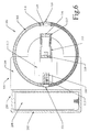
- Fig. 21 shows a sixth embodiment in the form of a hand-held referencing tool particularly suitable for levelling, plumbing, aligning and projecting reference lines over a generally flat surface.
- Cylindrical assembly 300 is mounted in a holding case 700 of hollow rectangular section and is enclosed at one end of the tool by a curved clear window 705 which can be a friction fit with the case.
- windows 710 and 720 At the other end of the tool are three translucent windows 710 and 720. These windows have markings parallel to the top and bottom surfaces of the tool. When the two halves of cylindrical assembly 300 are arranged so that the line of laser light is transmitted through the body of the tool, the line projected across windows 710 and 720 will snow the alignment of the body of the tool with the preset angle.
- Cylindrical assembly 300 is similar to that illustrated in Figures 2a, 2b and 2c, but the eccentric weight 307 used previously has been replaced by batteries 208.
- pointed screws 206, 212 used previously have been replaced by a magnetised suspension assembly including a magnetised axial rod 730, the ends of which are held suspended magnetically in housings 740 of similar polarity.
- the housing and the rod end repel each other, and cylindrical assembly 300 can align gravitationally with no error introduced by friction at the rod ends.
- a proximity switch may be used to interrupt the electrical flow from the batteries to the laser diode.
Abstract
Description
- The invention is generally in the field of hand tools and levelling devices, and is more particularly concerned with the relatively precise marking of reference lines at any angle over a generally flat surface. The compactness, portability and relative accuracy of the invention render it of great usefulness to the professional builder and carpenter, while the ease of use and lack of skill needed in the operation of the invention make it of particular use to the DIY enthusiast.
- There have been a number of surveying and carpentry tools employing the use of beams of light generated by lasers. Most of these have concerned themselves with producing a horizontal plane of light from a floor or tripod-mounted unit and have addressed the needs of large constructional and civil engineering works. Early devices were relatively cumbersome, required precise manual levelling and utilised helium-neon lasers which required mains electricity supplies.
- According to the present invention, however, a laser light referencing tool comprises laser means for emitting a visible laser beam, portable power means for powering the laser means, and gravity-responsive directional means for establishing a datum direction for the laser means.
- The gravity-responsive means may include one or more batteries and/or may include one or more other weights.
- Preferably, control means is provided for enabling the laser means to be moved in a controlled manner so that the visible laser beam is emitted in a controlled direction relative to said datum direction.
- Said control means may be based on friction and the friction may be adjustable - said control means may be such as to allow the laser means to be fully rotatable, rather than merely pivotable, to allow the laser means to be set at any selected angle within 360°.
- It will thus be appreciated that'the present invention can provide a hand-portable tool capable of producing a reference line at any angle in any single plane. When used as a levelling device against a generally vertical surface, a reference line will be projected over that surface generally at the horizontal or at any preset angle away from the horizontal, despite the angle at which the tool is held against the substantially vertical surface, and without the need for any pre-levelling of the instrument. It will also be appreciated that the tool of the present invention can be rugged and lightweight as well as compact and portable.
- Preferably, the present invention is a small rugged referencing tool which is compact and light enough to be easily held in the palm of one hand, leaving the other hand free to mark the generally vertical surface over which the reference line is projected by the tool. The operator may mark such a line over as wide a span as his or her arms will allow. When placed against the generally vertical surface, the case of the tool or any attached handle may be held at any angle, and in either hand without altering the angle of the displayed reference line. The tool may also be placed on any convenient generally horizontal surface, or on a suitable stand or tripod, allowing a completely hands-free operation over the tool's range. This range is dependent only on the power of the laser means employed, and the quality of the optical elements used. Means are also disclosed as to how the tool may be fixed to the generally vertical surface being referenced, allowing similar hands-free operation.
- Attachments are described which enhance the tool's versatility, allowing it to be used to provide a visible reference line as an extension to a surface, (either substantially horizontal/vertical, at any preset angle away from the horizontal or along the same plane as the surface of origin), and as a tool for providing a visible reference line at any angle over any plane.
- A means of overcoming the obscuring effect of strong ambient light, such as direct sunlight, is also disclosed.
- Other arrangements are described which can provide a pair of reference points at the generally horizontal, or at any angle away from the generally horizontal, across open space.
- A first embodiment has a case containing batteries which supply power to a laser diode contained in a first axially pivoted cylindrical housing. This cylindrical housing and its contents are substantially in balance around its axis. Any imbalance in this housing may be rectified by an adjustable weight in the form of a fine balancing slug threaded into a balancing weight set in the housing. Via optical means including a collimating lens and a line producing lens, the laser diode produces a beam of light, divergent in a single plane only, along the radial line of the cylindrical housing. Thus, when placed close to and generally parallel to a generally vertical, generally flat surface, a horizontally divergent beam will strike the surface at an oblique angle, and a thin line of light of generally uniform thickness will be projected over that surface.
- Axially attached to the laser diode housing is a second cylindrical housing containing an eccentric weight. The effect of gravity on this eccentric weight makes a zero to one hundred and eighty degree line marked on the outside of the second cylindrical housing align generally with the horizontal. The alignment of the second cylindrical housing may be finely adjusted by a balancing slug threaded into the eccentric weight. When the two cylindrical housings are rotated relative to each other, friction between the two housings maintains the angle of rotation. As the cylindrical housing containing the laser diode and its associated circuitry is generally in balance around its axis, whatever the preset angle of rotation of the laser diode housing, no significant deviation will be experienced by the cylindrical housing containing the eccentric weight. Thus, the beam of visible light output by the laser diode may be preset to the horizontal or any angle away from the horizontal.
- Adjustable point bearings on the axis of the cylindrical laser diode/weight assembly not only allow the free rotation of that assembly, but, being made of an electrically conductive material, supply electrical power from the batteries in the case of the tool to the laser diode assembly, without the need for connecting wires which would impede the free rotation of the assembly.
- A switch can be included in the tool to interrupt the electrical supply, and an electronic timing circuit can also be included to provide an automatic shut-down of power after a predetermined time in order that battery life may be conserved. A visible indicator of the laser diode's operation, such as a low-power flashing LED might also be used. A mechanical locking device can allow the cylindrical housing containing the eccentric weight to be rendered immobile relative to the case of the tool, while still allowing the cylindrical housing containing the laser diode assembly to be rotated. Thus, a line of light at a preset angle relative to the outside surface of the case of the tool may be projected over any generally flat surface against which, or on which the tool is placed.
- A second embodiment utilises a pair of laser diodes mounted back to back in a cylindrical housing. Two beams, axially in general alignment are projected from the housing via optical means including collimating lenses and plain lenses. This cylindrical housing is connected to a cylindrical housing containing an eccentric weight as detailed above, and may be similarly rotated relative to it. With the tool held generally vertically, two beams of substantially non-divergent laser light are projected radially at the horizontal, or at a preset angle away from the horizontal. Two points are illuminated by the beams of light, the angle between them relative to the horizontal being determined by the angle of rotation of one cylindrical housing relative to the other.
- A third embodiment has a single laser diode mounted radially in, and pointing to the centre of, a cylindrical housing. At the centre of this housing is fixed a right-angled mirror. This mirror splits the beam of laser light and projects two beams radially from the housing in a similar manner to that detailed above.
- A fourth embodiment has a laser diode, associated circuitry, collimating lens, line generating lens, balancing weight and fine balancing slug mounted in a cylindrical housing as in the first embodiment. The cylindrical housing is axially attached via studs to one end of an elongate pendular assembly including two composite strips of electrically conducting and non-conducting material. Friction prevents the cylindrical housing from rotating freely, but this friction may be overcome by finger pressure. Set into the other end of these strips are metal discs with conical depressions. Threaded pointed screws, attached to a case of the tool, engage in these depressions. Electrically conducting strips connect these screws with wires which in turn connect via a switch to batteries. Electrical power is thus supplied to the laser diode via the pointed screws, from which the composite strips and cylindrical housing depend. Mounted in the cylindrical housing are two identical weights. The cylindrical housing is thus generally in balance around its axis. Markings on the surface of the cylindrical housing allow the housing to be rotated to a preset angle relative to the composite strips and hence relative to the generally vertical. Thus a line of light at a preset angle may be projected over a generally vertical, generally flat surface as detailed in the first embodiment. The other end of the elongate pendular assembly is rotatably mounted to a holding case.
- A fifth embodiment has a laser diode, associated circuitry, collimating lens and line generating lens mounted in a cylindrical housing. The cylindrical housing is axially attached via studs to one end of an elongate pendular assembly in the form of a battery case. Friction prevents the cylindrical housing from rotating freely, but this friction may be overcome by finger pressure. Said one end of the elongate pendular assembly is also rotatably mounted to a holding case, the battery case/laser diode housing assembly being pivotable relative to the holding case by means of pointed threaded screws and metal rings with conical depressions as described in the first embodiment. The battery case of this fifth embodiment performs the function of the axially connected eccentric weight housing of the first embodiment. Gravity acts on it so that it hangs generally vertically from the pointed screw bearings. When the cylindrical housing is rotated to a preset angle relative to the battery case, a line of light at a preset angle may be projected over a generally vertical, generally flat surface as detailed in the first embodiment.
- A sixth embodiment, which is the currently preferred embodiment, is similar to the first embodiment in including first and second cylindrical housings whose relative rotational positions are controlled by friction. However, the gravity-responsive directional means now comprises the portable power means (one or more batteries). Said first and second cylindrical housings are rotatably mounted at one end of a holding case, and are rotatably mounted to the holding case by means of a magnetised suspension assembly. Access to said first and second cylindrical housings is via a curved clear window which is a friction fit with the holding case. The other end of the holding case is provided with a plurality of translucent windows carrying parallel markings. There may be three translucent windows arranged respectively at said other end and at two sides of the holding case.
- Individual features of the various embodiments may be combined differently.
- The accompanying schematic drawings serve to illustrate preferred embodiments of the present invention so that the principles of the invention may be fully explained.
- Figures 1(a), 1(b) and 1(c) are, respectively, life-size front, underneath and right end views of a hand-held referencing tool in accordance with a first embodiment of the invention for levelling, plumbing, aligning and projecting reference lines over a generally flat surface.
- Figures 2(a), 2(b) and 2(c) are sectional views through Figures 1 (a), 1 (b) and 1 (c).
- Figure 3 is a twice life-size longitudinal sectional view through the first embodiment.
- Figure 4 is a twice life-size latitudinal sectional view through the first embodiment.
- Figure 5 is a twice life-size elevational sectional view through the first embodiment, showing particularly the cylindrical case containing the eccentric weight.
- Figure 6 is a twice life-size elevational sectional view through the first embodiment, showing particularly the cylindrical case containing the laser diode assembly, optics and adjustable balancing weight.
- Figure 7 is a twice life-size elevational sectional view through part of a second embodiment, showing particularly a cylindrical case containing a double laser diode assembly.
- Figure 8 is a twice life-size elevational sectional view through part of a third embodiment, showing particularly a cylindrical case containing a laser diode assembly, adjustable balancing weight and beam splitting mirror.
- Figures 9(a), 9(b), 9(c), 9(d) and 9(e) show, respectively, front, underneath, right end, rear and partial enlargement views of a carrying case/extension handle to enable hands-free operation of the tool.
- Figures 10(a), 10(b), 10(c) and 10(d) show, respectively, front, underneath, right end and rear views of the carrying case/extension handle in different combinations with the tool shown in Figure 10(e) which is a slight modification of the tool of Figure 1 (a).
- Figures 11(a), 11(b) and 11(c) correspond to Figures 10(a), 10(b) and 10(c), but show a suitable accessory for enhancing the tool's versatility, allowing it to be used to provide a visible reference line as an extension to a surface, (either substantially horizontal/vertical or along the same plane as the surface of origin) , and as a tool for providing a visible reference line at any angle over any plane.
- Figures 12(a), 12(b) and 12(c) show, respectively, front, side and lower end views of a marking accessory for conditions of very bright ambient light.
- Figure 13 is a life-size view of a fourth embodiment, in which the cylindrical assembly is pivotable relative to the case.
- Figures 14(a), 14(b) and 14(c) correspond to Figures 2(a), 2(b) and 2(c), but show the fourth embodiment.
- Figures 15, 16 and 17 correspond to Figures 3, 4 and 6 but are one and a half times life-size views of the fourth embodiment.
- Figures 18(a), 18(b) and 18(c) are, respectively, life-size front (opened), front (closed) and right end (opened) views of a fifth embodiment, in which the tool is pivotable relative to a slip case.
- Figures 19 and 20 are, respectively, one and a half times life-size sectional views through Figures 18(a) and 18(c).
- Figures 21(a), 21(b) and 21(c) show, respectively, life-size front, underneath and right end sectional views of a sixth embodiment of a laser light referencing tool according to the present invention.
-
- In all of the accompanying drawings, like components are given like reference numbers.
- A referencing
tool 100 of the invention is illustrated generally in Figs. 1 and 2, and in detail in Figs. 3 to 6, and comprisescase 200 andcylindrical assembly 300 manufactured from electrically non-conducting material. -
Case 200 hasbattery compartment 202 containingbatteries 208,front cover 201 andrear cover 209. - To the
front cover 201 are attached on/offswitch 203 for interrupting the electrical supply from thebatteries 208, and lockingdevice 204 which, when engaged, preventscylindrical case 301 from being rotated by engaging in cut-outportion 304 ofcylindrical case 301. - Also attached to the
front cover 201 is electrically conducting strip ofmetal 205. One end of this strip is connected electrically to one pole ofbatteries 208 viawires 207 andswitch 203. The other end ofstrip 205 contains threadedscrew 206. This threaded screw is pointed at one end. This point engages in a conical depression let intometal disc 305 which is mounted oncylindrical assembly 300. - On
rear cover 209 there is asimilar strip 211,wire 210 and pointed threadedscrew 212 which engagesdisc 306. When adjusted to the correct tension, screws 206 and 212 engage withdiscs cylindrical assembly 300 in such a way that electricity is supplied tocylindrical assembly 300 while allowingcylindrical assembly 300 to rotate freely. -
Slot 213 is provided in the bottom ofcase 200 for purposes set forth hereinafter. -
Cylindrical assembly 300 comprises cylindrical case 301 (first housing) and cylindrical case 302 (second housing) connected axially bystud 312. The friction betweencylindrical cases cylindrical cases -
Cylindrical case 301 hasfront cover 303 on which is mountedmetal disc 305. Contained withincylindrical case 301 areeccentric weight 307 with adjustablefine balancing slug 311, andwire 308 which carries electricity fromdisc 305 tostud 312. When lockingdevice 204 is released,cylindrical case 301 is turned by the effect of gravity onweight 307 andslug 311. -
Cylindrical case 302 has a rear cover 303' on which are carriedalignment markers metal disc 306. Contained withincylindrical case 302 arelaser diode 314, its associatedcircuitry 313,optics weight 310 with adjustable fine balancing slug 311', andwires 309 electrically connectinglaser diode circuitry 313 tostud 312 anddisc 306. -
Laser diode 314 in threaded barrel-shapedholder 315 is mounted radially incylindrical case 302. A visible beam of light is generated bylaser diode 314. This divergent beam is collimated by collimatinglens 316 mounted in adjustable threaded barrel-shapedholder 317 and the resultant parallel beam of light is made to diverge solely in the generally horizontal plane byline generating lens 319 which is mounted inlens holder 318. Withrear cover 209 held against, or in close proximity and generally parallel to, a generally vertical, generally flat surface, this beam will be visible over that surface as a line of light. By rotatingcylindrical case 302 relative tocylindrical case 301, and aligning themarker 320 denoting the centre ofline generating lens 319 with markings oncylindrical case 301 denoting the desired angle away from the horizontal, a visible reference line of light may be projected generally along the horizontal plane, or along any chosen angle away from the horizontal.Alignment marker 320 andrear alignment marker 321 indicate the axis along which the beam of light will be projected. In a similar way, when two points on a generally vertical surface are illuminated by the projected line of light, the angle between them, relative to the generally horizontal, may be determined by reading off the degree scale on the exterior ofcylindrical case 301. - Fig. 7 shows an alternative embodiment of the invention. Save for the components contained in
cylindrical case 302a, which replacescylindrical case 302, the tool is identical to the embodiment of the invention described astool 100. - In Fig. 7 a pair of
laser diodes 314 in threaded barrel-shapedholders 315 are mounted radially incylindrical case 302a.Control circuitry 313 is connected tolaser diodes 314 via connectingwires 324. Balancingweights 310 and adjustablefine balancing slugs 311 have been omitted for clarity. Visible beams of light are generated bylaser diodes 314. These divergent beams are collimated by collimatinglenses 316 mounted in adjustable threaded barrel-shapedholders 317 and the resultant parallel beams of light are projected throughplain lenses 322 which are mounted inlens holders 318. - When this alterative tool is held generally vertically, two points of light will be projected radially along the horizontal or, by rotating
cylindrical case 302a relative tocylindrical case 301 as detailed above, at any preset angle away from the horizontal. - In a similar way, when two marked points are illuminated by the projected points of light, the angle between them, relative to the generally horizontal, may be determined by reading off the degree scale marked on the exterior of
cylindrical case 301. - Fig. 8 shows an alterative embodiment to that shown in Fig. 7. A
laser diode 314, in threaded barrel-shapedholder 315 is mounted radially incylindrical case 302b. A visible beam of light is generated bylaser diode 314. This divergent beam is collimated by collimatinglens 316 mounted in adjustable threaded barrel-shapedholder 317 and the resultant parallel beam of light is directed towards the centre ofcylindrical case 302b, where it is split by right-angledmirror 323. Points of light are projected from the tool as detailed above. - Figs. 9 and 10 show a suitable case for carrying the tool and attaching it by various means to a substantially vertical surface, thus allowing hands-free operation within the range of the tool.
Case 400 is open at one end. Raisedridge 402 engages withslot 213, thereby ensuring that atool 100 of the present invention can only be fixed intocase 400 in two ways. For carriage and storage,cylindrical assembly 300 enters first intocase 400. For operation of the tool,case 200 is entered first intocase 400. The cut-outsection 406 incase 400 allows operation ofswitch 203 and lockingdevice 204.Slots case 400 allow the case and tool to be attached to a substantially vertical surface. Various means 405 may be employed. These could include pin-type fixings, or suction cups or magnets, according to the type of surface. When attached by means ofslot 403, the fixing device will be generally at the axis ofcylindrical assembly 300, thus allowing for easy and accurate hands-free marking, up to the limit of the range of the tool.Slot 404 could be used to achieve a hands-free plumb-line. Raisedstuds 401 engage indepressions 407 on the outside of the tool, to hold tool and case securely together. - Fig. 11 shows a suitable accessory for enhancing the tool's versatility, allowing it to be used to provide a visible reference line as an extension to a surface, either substantially horizontal/vertical or along the same plane as the surface of origin, and as a tool for providing a visible reference line at any angle over any plane.
Case 500 is open at both ends, thus allowing atool 100 of the present invention to be mounted for right or left-handed operation. Tool and case engage with each other in the way described above. Referring to Fig. 11, whencase 500 is placed on abody 502 to be referenced, the projected beam of light will be generally in the same plane as thesurface 501 on which an exterior abutment surface of the tool is placed. Whencylindrical assembly 300 is locked off at the zero degree position, the projected beam of light will be generally in the same plane as the surface to be referenced. Any deviations on the surface being referenced will thus be highlighted. When locked off, withcylindrical case 302 rotated away from the zero degree mark, reference lines of any preset angle may thus be projected across any plane. Thus, for instance, a simple and accurate means of marking up sheet materials may be achieved. - Fig. 12 shows an auxiliary tool for providing a means of overcoming the obscuring effect of strong ambient light. A
small clip 600 is clipped onto a pencil orpen 601. Running down the centre of the face ofclip 600 is a clearly markedwhite line 602. When placed in the path of the beam of light projected fromtool 100, the red light of the laser will show clearly against thewhite line 602 ofclip 600. Even when the ambient light is very strong, side andtop extensions 603 ofclip 600 will keepline 602 in shadow, thus increasing the contrast and visibility of the projected beam of light. Althoughclip 600 will not be needed in most working conditions, it is so small and lightweight that it can easily be included in the toolkit as a matter of course. - Figs. 13 to 17 show a fourth embodiment in which, in addition to
case 200 andcylindrical assembly 300, there is an intermediatependular assembly 360. - The
case 200 hasbattery compartment 202 containingbatteries 208,front cover 201 andrear cover 209. - To the
front cover 201 is attached on/offswitch 203 for interrupting the electrical supply from thebatteries 208. Also attached to thefront cover 201 is electrically conducting strip ofmetal 205. One end of this strip is connected electrically to one pole ofbatteries 208 viawires 207 andswitch 203. The other end ofstrip 205 contains threadedscrew 206. This threaded screw is pointed at one end. This point engages in a conical depression let intometal disc 305 which is mounted onpendular assembly 360. - On
rear cover 209 there is asimilar strip 211,wire 210 and pointed threadedscrew 212 which engagesdisc 306 which is mounted onpendular assembly 360. -
Pendular assembly 360 comprises front and rear electricallynon-conducting cover plates metal strips metal discs non-conducting spacer 354. -
Studs 312 connectcylindrical assembly 300 physically and electrically withpendular assembly 360. Friction preventscylindrical assembly 300 from rotating freely, but this friction may be overcome by finger pressure, thus enablingcylindrical assembly 300 to be rotated to a preset angle relative topendular assembly 360. Markings on the outside ofcylindrical housing 302 allow the preset degree of rotation ofcylindrical assembly 300, relative to the generally horizontal, to be viewed through cut-outwindow 215 inpendular assembly 360. - When adjusted to the correct tension, screws 206 and 212 engage with
discs cylindrical assembly 300 viametal strips studs 312, while allowingpendular assembly 360 to pivot freely aboutscrews -
Cylindrical assembly 300 comprisescylindrical housing 302 and rear cover 303'. Contained withincylindrical housing 302 arelaser diode 314, its associatedcircuitry 313,optics weight 310 with adjustable fine balancing slug 311',wires 309 electrically connectinglaser diode circuitry 313 tostuds 312, and finally two matchedweights 307. These weights give mass tocylindrical assembly 300, mounted at the end ofpendular assembly 360, enablingpendular assembly 360 to align itself gravitationally with the generally vertical. Two weights are needed, as well as balancingweight 310 and fine balancing slug 311', so thatcylindrical assembly 300 is generally in balance around its axis. Thus, whencylindrical assembly 300 is manually rotated to a preset angle, no bias is introduced which might deviatependular assembly 360 away from the generally vertical. -
Laser diode 314 in threaded barrel-shapedholder 315 is mounted radially incylindrical housing 302. A visible beam of light is generated bylaser diode 314. This divergent beam is collimated by collimatinglens 316 mounted in adjustable threaded barrel-shapedholder 317 and the resultant parallel beam of light is made to diverge solely in the generally horizontal plane byline generating lens 319 which is mounted inlens holder 318. Withrear cover 209 held against, or in close proximity and generally parallel to, a generally vertical, generally flat surface, this beam will be visible over that surface as a line of light. By rotatingcylindrical assembly 300 relative topendular assembly 360, and aligning markings on the outside ofcylindrical housing 302 with markings on cut-outwindow 215 ofpendular assembly 360 denoting the desired angle away from the horizontal, a visible reference line of light may be projected generally along the horizontal plane, or along any chosen angle away from the horizontal. In a similar way, when two points on a generally vertical surface are illuminated by the projected line of light, the angle between them, relative to the generally horizontal, may be determined by reading off the degree scale on the exterior ofcylindrical housing 302. - Figs. 18 to 20 show a fifth embodiment which differs from the fourth embodiment mainly in that here
case 200 acts as a pendulum as a result of being pivotable relative to slip case/handle 700. - The slip case/
handle 700 has afront plate 701 andrear plate 702 rigidly connected at one end. At the other end are set threaded, pointedscrews metal discs -
Case 200 hasbattery compartment 202 containingbatteries 208,weight 307 andfine balancing slug 311,front cover 350 andrear cover 352. - To
front cover 350 is attached on/offswitch 203 for interrupting the electrical supply from thebatteries 208. Also attached tofront cover 350 is electrically conductingmetal strip 205. One end of this strip is connected electrically to one pole ofbatteries 208 viawires 207 andswitch 203. The other end ofstrip 205 is attached tometal disc 305 andmetal stud 312. - On
rear cover 352 there is asimilar strip 211,wire 210,disc 306 andstud 312. -
Studs 312 connectcylindrical assembly 300 physically and electrically withcase 200. Friction preventscylindrical assembly 300 from rotating freely relative tocase 200, but this friction may be overcome by finger pressure, thus enablingcylindrical assembly 300 to be rotated to a preset angle relative tocase 200. Markings on the outside ofcylindrical housing 302 allow the preset degree of rotation ofcylindrical assembly 300, relative to the generally horizontal, to be viewed through cut-outwindow 214 incase 200. - When adjusted to the correct tension, screws 206 and 212 engage with
discs case 200 andcylindrical assembly 300 may pivot freely aboutscrews case 200 to align itself gravitationally with the generally vertical. Ascylindrical assembly 300 is frictionally attached tocase 200, this generally vertical alignment will also turncylindrical assembly 300 about its axis. Any imbalance incase 200 may be rectified by the adjustment offine balancing slug 311. -
Cylindrical assembly 300 comprisescylindrical housing 302 and rear cover 303'. Contained withincylindrical housing 302 arelaser diode 314 connected electrically bywires 324 to its associatedcircuitry 313,optics wires 309 electrically connectinglaser diode circuitry 313 tostuds 312. -
Laser diode 314 in threaded barrel-shapedholder 315 is mounted radially incylindrical housing 302. A visible beam of light is generated bylaser diode 314. This divergent beam is collimated by collimatinglens 316 mounted in adjustable threaded barrel-shaped holder, 317 and the resultant parallel beam of light is made to diverge solely in the generally horizontal plane byTine generating lens 319 which is mounted inlens holder 318. Withrear cover 702 held against, or in close proximity and generally parallel to, a generally vertical, generally flat surface, this beam will be visible over that surface as a line of light. By rotatingcylindrical assembly 300 relative tocase 200, and aligning markings on the outside ofcylindrical housing 302 with markings on cut-outwindow 214 ofcase 200 denoting the desired angle away from the horizontal, a visible reference line of light may be projected generally along the horizontal plane, or along any chosen angle away from the horizontal. In a similar way, when two points on a generally vertical surface are illuminated by the projected line of light, the angle between them, relative to the generally horizontal, may be determined by reading off the degree scale on the exterior ofcylindrical housing 302. - Fig. 21 shows a sixth embodiment in the form of a hand-held referencing tool particularly suitable for levelling, plumbing, aligning and projecting reference lines over a generally flat surface.
-
Cylindrical assembly 300 is mounted in a holdingcase 700 of hollow rectangular section and is enclosed at one end of the tool by a curvedclear window 705 which can be a friction fit with the case. - At the other end of the tool are three
translucent windows cylindrical assembly 300 are arranged so that the line of laser light is transmitted through the body of the tool, the line projected acrosswindows -
Cylindrical assembly 300, is similar to that illustrated in Figures 2a, 2b and 2c, but theeccentric weight 307 used previously has been replaced bybatteries 208. - Moreover, the pointed
screws axial rod 730, the ends of which are held suspended magnetically inhousings 740 of similar polarity. - Thus, at each end of the rod, the housing and the rod end repel each other, and
cylindrical assembly 300 can align gravitationally with no error introduced by friction at the rod ends. - A proximity switch may be used to interrupt the electrical flow from the batteries to the laser diode.
- Thus, in addition to the versatility of the tool when used in line projecting mode, the functionality of a traditional spirit-level may be mimicked, but with greater accuracy, visibility and ease of use.
Claims (21)
- A laser light referencing tool comprising laser means for emitting a visible laser beam, portable power means for powering the laser means, and gravity-responsive directional means for establishing a datum direction for the laser means.
- A laser light referencing tool according to claim 1, in which control means is provided for enabling the laser means to be moved in a controlled manner so that the visible laser beam is emitted in a controlled direction relative to said datum direction.
- A laser light referencing tool according to claim 2, in which the control means is based on friction.
- A laser light referencing tool according to claim 3, in which the friction is adjustable.
- A laser light referencing tool according to any preceding claim, in which the laser means comprises one or more laser diodes, and the portable power means comprises one or more batteries.
- A laser light referencing tool according to any one of claims 1 to 5, in which optical means is provided such that the visible laser beam is divergent in a single plane.
- A laser light referencing tool according to any one of claims 1 to 5, in which optical means is provided such that the visible laser beam is substantially non-divergent.
- A laser light referencing tool according to any preceding claim, in which two visible laser beams are produced directed along the same line but in opposite directions.
- A laser light referencing tool according to any one of claims 1 to 8, in which the laser means is contained within a first cylindrical housing, and the gravity-responsive directional means is contained within a second cylindrical housing, said first and second cylindrical housings being axially attached to one another to permit relative rotation therebetween.
- A laser light referencing tool according to claim 9, in which an adjustable weight is contained in said first cylindrical housing for allowing said first cylindrical housing and its contents to be maintained substantially in balance around its axis.
- A laser light referencing tool according to claim 9 or claim 10, in which a mechanical locking device is provided for allowing said second cylindrical housing and its contents to be rendered immobile.
- A laser light referencing tool according to any one of claims 9 to 11, in which the laser means, the portable power means and the gravity-responsive directional means are insertable within a holding case.
- A laser light referencing tool according to claim 12, in which the holding case comprises an exterior abutment surface lying substantially in the plane of the visible laser beam.
- A laser light referencing tool according to any one of claims 1 to 8, in which the laser means is contained within a cylindrical housing which is rotatably mounted at one end of an elongate pendular assembly with the other end of the elongate pendular assembly being rotatably mounted to a holding case.
- A laser light referencing tool according to any one of claims 1 to 8, in which the laser means is contained within a cylindrical housing which is rotatably mounted at one end of an elongate pendular assembly with said one end of the elongate pendular assembly also being rotatable mounted to a holding case.
- A laser light referencing tool according to any one of claims 1 to 10, in which the gravity-responsive directional means comprises the portable power means.
- A laser light referencing tool according to claim 9 and claim 16, in which said first and second cylindrical housings are rotatably mounted at one end of a holding case.
- A laser light referencing tool according to claim 17, in which said first and second cylindrical housings are rotatably mounted to the holding case by means of a magnetised suspension assembly.
- A laser light referencing tool according to claim 17 or claim 18, in which access to said first and second cylindrical housings is via a curved clear window which is a friction fit with the holding case.
- A laser light referencing tool according to any one of claims 17 to 19, in which the other end of the holding case is provided with a plurality of translucent windows carrying parallel markings.
- A laser light referencing tool according to claim 20, in which there are three translucent windows arranged respectively at said other end and at two sides of the holding case.
Priority Applications (2)
| Application Number | Priority Date | Filing Date | Title |
|---|---|---|---|
| EP07114445A EP1852678B1 (en) | 1996-09-10 | 1997-09-10 | Laser light referencing tool |
| EP07113280A EP1852677B1 (en) | 1996-09-10 | 1997-09-10 | Laser light referencing tool |
Applications Claiming Priority (5)
| Application Number | Priority Date | Filing Date | Title |
|---|---|---|---|
| GB9618834 | 1996-09-10 | ||
| GBGB9618834.7A GB9618834D0 (en) | 1996-09-10 | 1996-09-10 | Laser light referencing tool |
| GBGB9714878.7A GB9714878D0 (en) | 1997-07-15 | 1997-07-15 | Laser light referencing tool |
| GB9714878 | 1997-07-15 | ||
| EP97939100A EP1012539B2 (en) | 1996-09-10 | 1997-09-10 | Laser light referencing tool |
Related Parent Applications (1)
| Application Number | Title | Priority Date | Filing Date |
|---|---|---|---|
| EP97939100A Division EP1012539B2 (en) | 1996-09-10 | 1997-09-10 | Laser light referencing tool |
Related Child Applications (2)
| Application Number | Title | Priority Date | Filing Date |
|---|---|---|---|
| EP07114445A Division EP1852678B1 (en) | 1996-09-10 | 1997-09-10 | Laser light referencing tool |
| EP07113280A Division EP1852677B1 (en) | 1996-09-10 | 1997-09-10 | Laser light referencing tool |
Publications (2)
| Publication Number | Publication Date |
|---|---|
| EP1522820A1 true EP1522820A1 (en) | 2005-04-13 |
| EP1522820B1 EP1522820B1 (en) | 2007-10-10 |
Family
ID=26310004
Family Applications (4)
| Application Number | Title | Priority Date | Filing Date |
|---|---|---|---|
| EP97939100A Expired - Lifetime EP1012539B2 (en) | 1996-09-10 | 1997-09-10 | Laser light referencing tool |
| EP07114445A Expired - Lifetime EP1852678B1 (en) | 1996-09-10 | 1997-09-10 | Laser light referencing tool |
| EP05000309A Expired - Lifetime EP1522820B1 (en) | 1996-09-10 | 1997-09-10 | Laser light referencing tool |
| EP07113280A Expired - Lifetime EP1852677B1 (en) | 1996-09-10 | 1997-09-10 | Laser light referencing tool |
Family Applications Before (2)
| Application Number | Title | Priority Date | Filing Date |
|---|---|---|---|
| EP97939100A Expired - Lifetime EP1012539B2 (en) | 1996-09-10 | 1997-09-10 | Laser light referencing tool |
| EP07114445A Expired - Lifetime EP1852678B1 (en) | 1996-09-10 | 1997-09-10 | Laser light referencing tool |
Family Applications After (1)
| Application Number | Title | Priority Date | Filing Date |
|---|---|---|---|
| EP07113280A Expired - Lifetime EP1852677B1 (en) | 1996-09-10 | 1997-09-10 | Laser light referencing tool |
Country Status (9)
| Country | Link |
|---|---|
| US (1) | US6351890B1 (en) |
| EP (4) | EP1012539B2 (en) |
| AT (4) | ATE413587T1 (en) |
| AU (1) | AU4131697A (en) |
| DE (4) | DE69739097D1 (en) |
| DK (3) | DK1852678T3 (en) |
| ES (3) | ES2316136T3 (en) |
| PT (1) | PT1522820E (en) |
| WO (1) | WO1998011407A1 (en) |
Families Citing this family (42)
| Publication number | Priority date | Publication date | Assignee | Title |
|---|---|---|---|---|
| US6532675B2 (en) * | 2001-04-18 | 2003-03-18 | Guy Letourneau | Device for measuring the angle of orientation with reference to a known frame of reference between a first object having a first axis and a second remote destination |
| WO2002093108A1 (en) * | 2001-05-15 | 2002-11-21 | American Tool Companies, Inc. | Laser line generating device |
| US7278218B2 (en) * | 2003-06-18 | 2007-10-09 | Irwin Industrial Tool Company | Laser line generating device with swivel base |
| US7513051B2 (en) * | 2001-05-15 | 2009-04-07 | Irwin Industrial Tool Company | Laser line generating device with graduated base |
| WO2003046477A1 (en) * | 2001-11-30 | 2003-06-05 | Mortlach Holdings Pty Ltd | Adaptor for a line of sight measurement instrument |
| US6914930B2 (en) * | 2002-05-31 | 2005-07-05 | Black & Decker Inc. | Laser level |
| US7031367B2 (en) * | 2002-05-31 | 2006-04-18 | Black & Decker Inc. | Laser level |
| GB2415058B (en) * | 2002-05-31 | 2006-07-12 | Black & Decker Inc | Laser level |
| US20060021237A1 (en) * | 2002-05-31 | 2006-02-02 | Marshall James D | Measuring and leveling device |
| US7513052B2 (en) * | 2002-10-22 | 2009-04-07 | Black And Decker | Light line generating device |
| US7523558B2 (en) | 2002-10-22 | 2009-04-28 | Black And Decker | Tool incorporating a light line generating device |
| US6810595B2 (en) * | 2002-12-24 | 2004-11-02 | Wing-Sheung Chan | Laser angle guide assembly for computed tomography and method for the same |
| CN2588326Y (en) * | 2002-12-27 | 2003-11-26 | 南京泉峰国际贸易有限公司 | Laser line marking device |
| US7269907B2 (en) * | 2003-07-01 | 2007-09-18 | Irwin Industrial Tool Company | Laser line generating device with swivel base |
| US7137209B2 (en) * | 2003-08-01 | 2006-11-21 | Robert Theodore Northern | Level and protractor |
| JP2005075560A (en) * | 2003-09-01 | 2005-03-24 | Ktf:Kk | Adhesive tape cutter |
| GB2411471A (en) | 2004-02-27 | 2005-08-31 | Nigel Emlyn Williams | A frictional pivot for gravitational alignment |
| CN2718518Y (en) * | 2004-06-18 | 2005-08-17 | 南京德朔实业有限公司 | Laser striping machine |
| US7487596B2 (en) * | 2004-06-25 | 2009-02-10 | Irwin Industrial Tool Company | Laser line projected on an edge of a surface |
| US7178250B2 (en) * | 2004-07-21 | 2007-02-20 | Irwin Industrial Tool Company | Intersecting laser line generating device |
| US6981331B1 (en) * | 2004-07-30 | 2006-01-03 | Poe Jr John W | Fork level indicator with magnetic dampening means |
| US7181854B2 (en) * | 2004-08-17 | 2007-02-27 | Eastway Fair Company Limited | Laser leveling device having a suction mounting arrangement |
| US7191532B2 (en) * | 2004-08-17 | 2007-03-20 | Eastway Fair Company Limited | Modular tool assembly having a vacuum mounting arrangement |
| US7174647B2 (en) * | 2004-09-20 | 2007-02-13 | Zircon Corporation | Laser line projector with spherically rotatable support and level/plumb indicators for the support |
| CN2872305Y (en) * | 2005-06-30 | 2007-02-21 | 南京德朔实业有限公司 | Laser scratcher |
| US7497019B2 (en) * | 2005-08-04 | 2009-03-03 | Irwin Industrial Tool Company | Laser reference device |
| US7328516B2 (en) * | 2005-08-05 | 2008-02-12 | Irwin Industrial Tool Company | Laser level |
| US7377045B2 (en) * | 2005-09-12 | 2008-05-27 | Irwin Industrial Tool Company | Laser reference device |
| US20070079516A1 (en) * | 2005-10-07 | 2007-04-12 | Eckstein Patrick J | Device for marking a straight line |
| US7520062B2 (en) * | 2005-12-06 | 2009-04-21 | Robert Bosch Tool Corporation | Light-plane projecting apparatus and lens |
| US20080052927A1 (en) * | 2006-09-05 | 2008-03-06 | Eastway Fair Company Limited | Self-leveling line generator |
| US20080052926A1 (en) * | 2006-09-05 | 2008-03-06 | Eastway Fair Company Limited | Gravity dial level indicator for line generator |
| US20080062669A1 (en) * | 2006-09-07 | 2008-03-13 | Parel Thomas M | Gravity dial level indicator for line generator |
| US7591075B2 (en) * | 2006-09-28 | 2009-09-22 | Techtronic Power Tools Technology Limited | Self-leveling mechanism |
| DE202007001753U1 (en) * | 2006-12-29 | 2007-06-06 | STABILA Messgeräte Gustav Ullrich GmbH | Measuring device e.g. construction laser apparatus, has housing surrounded by cover that is pivoted around axis crossing housing, where cover has section that covers or uncovers radiation emission hole based on pivoting position of cover |
| CN201035149Y (en) * | 2007-01-19 | 2008-03-12 | 南京德朔实业有限公司 | Laser ranging device |
| CN201035148Y (en) * | 2007-01-19 | 2008-03-12 | 南京德朔实业有限公司 | Laser ranging device |
| US20090320302A1 (en) * | 2008-06-25 | 2009-12-31 | William Boyd | Square foot alignment device |
| US9441967B2 (en) | 2013-05-31 | 2016-09-13 | Stanley Black & Decker Inc. | Laser level system |
| US10422638B2 (en) * | 2016-05-12 | 2019-09-24 | Milwaukee Electric Tool Corporation | Level with rotating angle indicator |
| US10380392B2 (en) | 2016-06-14 | 2019-08-13 | Datalogic IP Tech, S.r.l. | Variable orientation scan engine |
| US11175136B2 (en) | 2018-03-09 | 2021-11-16 | Stanley Balck & Decker Inc. | Laser level |
Citations (5)
| Publication number | Priority date | Publication date | Assignee | Title |
|---|---|---|---|---|
| EP0341812A1 (en) * | 1988-04-08 | 1989-11-15 | Spectra Precision, Inc. | Level/Plumb indicator with tilt compensation |
| US5075977A (en) * | 1990-10-22 | 1991-12-31 | Spectra-Physics, Inc. | Automatic plumb and level tool |
| DE4442224A1 (en) * | 1994-11-26 | 1996-05-30 | Richard Franke | Laser measuring unit with at least one laser beam of rotatable located laser source |
| US5531031A (en) * | 1995-01-20 | 1996-07-02 | Green; Kevin D. | Laser level and square |
| EP0729053A2 (en) * | 1995-02-22 | 1996-08-28 | MICRO ITALIANA S.p.A. | Device for projecting a flat beam of diverging laser rays |
Family Cites Families (19)
| Publication number | Priority date | Publication date | Assignee | Title |
|---|---|---|---|---|
| US2693642A (en) † | 1954-11-09 | Line protractor | ||
| US2340122A (en) † | 1942-06-30 | 1944-01-25 | Gen Electric | Magnet suspension |
| US2859725A (en) † | 1957-11-22 | 1958-11-11 | Donald B Genasci | True vertical indicator |
| US2968873A (en) * | 1958-07-18 | 1961-01-24 | Oscar C Holderer | Clinometer assembly |
| US3427724A (en) † | 1965-09-20 | 1969-02-18 | Harold James Tracy | Indicating device |
| US4144653A (en) † | 1978-05-12 | 1979-03-20 | Gardner William L | Inclinometer |
| CH674573A5 (en) † | 1987-07-13 | 1990-06-15 | Wild Leitz Ag | |
| DE3838512C1 (en) † | 1988-11-13 | 1990-01-11 | Ronald 6114 Gross-Umstadt De Knittel | |
| US5121188A (en) † | 1990-05-16 | 1992-06-09 | Applied Laser Systems | Laser module assembly |
| IT1270911B (en) † | 1993-03-24 | 1997-05-13 | Micro Italiana Spa | GONIOMETER FOR MEASURING ANGLES WITH AT LEAST A LASER BEAM EMITTER |
| IT1271145B (en) † | 1993-04-07 | 1997-05-27 | Micro Italiana Spa | SELF-LEVELING LASER BEAM PROJECTOR ON A ROTATING BASE |
| US5446635A (en) * | 1993-06-24 | 1995-08-29 | Quarton, Inc. | Laser assembly for marking a line on a workpiece for guiding a cutting tool |
| US5552886A (en) * | 1994-03-01 | 1996-09-03 | Nikon Corporation | Laser beam transmitting apparatus |
| US5519942A (en) * | 1995-03-02 | 1996-05-28 | Webb; James | Levelling and transit system |
| US5666736A (en) * | 1995-10-13 | 1997-09-16 | Wen; Cheng-Kan | Self-adjusting level for determining leveling between two distant points |
| US5836081A (en) * | 1996-05-29 | 1998-11-17 | Charles F. Schroeder | Light beam leveling means and method |
| US5842282A (en) * | 1996-10-01 | 1998-12-01 | Opcom Inc. | Laser angle adjustment device for laser measuring instruments |
| IT1292923B1 (en) † | 1997-05-15 | 1999-02-11 | Massimo Moretti | LEVEL LASER WIRE. |
| US6012229A (en) * | 1998-03-26 | 2000-01-11 | Shiao; Hsuan-Sen | Combined leveling device and laser pointer |
-
1997
- 1997-09-10 AU AU41316/97A patent/AU4131697A/en not_active Abandoned
- 1997-09-10 AT AT07114445T patent/ATE413587T1/en not_active IP Right Cessation
- 1997-09-10 DK DK07114445T patent/DK1852678T3/en active
- 1997-09-10 DK DK07113280T patent/DK1852677T3/en active
- 1997-09-10 AT AT07113280T patent/ATE414259T1/en not_active IP Right Cessation
- 1997-09-10 DE DE69739097T patent/DE69739097D1/en not_active Expired - Lifetime
- 1997-09-10 AT AT05000309T patent/ATE375498T1/en not_active IP Right Cessation
- 1997-09-10 US US09/254,543 patent/US6351890B1/en not_active Expired - Fee Related
- 1997-09-10 ES ES07114445T patent/ES2316136T3/en not_active Expired - Lifetime
- 1997-09-10 EP EP97939100A patent/EP1012539B2/en not_active Expired - Lifetime
- 1997-09-10 EP EP07114445A patent/EP1852678B1/en not_active Expired - Lifetime
- 1997-09-10 WO PCT/GB1997/002488 patent/WO1998011407A1/en active IP Right Grant
- 1997-09-10 EP EP05000309A patent/EP1522820B1/en not_active Expired - Lifetime
- 1997-09-10 DE DE69732257T patent/DE69732257T3/en not_active Expired - Lifetime
- 1997-09-10 AT AT97939100T patent/ATE287079T1/en not_active IP Right Cessation
- 1997-09-10 DE DE69738207T patent/DE69738207T2/en not_active Expired - Lifetime
- 1997-09-10 EP EP07113280A patent/EP1852677B1/en not_active Expired - Lifetime
- 1997-09-10 ES ES07113280T patent/ES2316135T3/en not_active Expired - Lifetime
- 1997-09-10 PT PT05000309T patent/PT1522820E/en unknown
- 1997-09-10 DE DE69739111T patent/DE69739111D1/en not_active Expired - Lifetime
- 1997-09-10 DK DK05000309T patent/DK1522820T3/en active
- 1997-09-10 ES ES05000309T patent/ES2281314T3/en not_active Expired - Lifetime
Patent Citations (5)
| Publication number | Priority date | Publication date | Assignee | Title |
|---|---|---|---|---|
| EP0341812A1 (en) * | 1988-04-08 | 1989-11-15 | Spectra Precision, Inc. | Level/Plumb indicator with tilt compensation |
| US5075977A (en) * | 1990-10-22 | 1991-12-31 | Spectra-Physics, Inc. | Automatic plumb and level tool |
| DE4442224A1 (en) * | 1994-11-26 | 1996-05-30 | Richard Franke | Laser measuring unit with at least one laser beam of rotatable located laser source |
| US5531031A (en) * | 1995-01-20 | 1996-07-02 | Green; Kevin D. | Laser level and square |
| EP0729053A2 (en) * | 1995-02-22 | 1996-08-28 | MICRO ITALIANA S.p.A. | Device for projecting a flat beam of diverging laser rays |
Also Published As
| Publication number | Publication date |
|---|---|
| PT1522820E (en) | 2008-01-21 |
| ES2316135T3 (en) | 2009-04-01 |
| EP1852677A3 (en) | 2007-11-21 |
| DE69732257D1 (en) | 2005-02-17 |
| ES2281314T1 (en) | 2007-10-01 |
| EP1852677A2 (en) | 2007-11-07 |
| WO1998011407A1 (en) | 1998-03-19 |
| EP1012539A1 (en) | 2000-06-28 |
| EP1852677B1 (en) | 2008-11-12 |
| EP1852678A2 (en) | 2007-11-07 |
| DK1522820T3 (en) | 2008-01-28 |
| DE69732257T3 (en) | 2009-01-15 |
| DE69739097D1 (en) | 2008-12-18 |
| DK1852678T3 (en) | 2009-03-09 |
| ATE413587T1 (en) | 2008-11-15 |
| AU4131697A (en) | 1998-04-02 |
| DE69739111D1 (en) | 2008-12-24 |
| US6351890B1 (en) | 2002-03-05 |
| ES2281314T3 (en) | 2007-11-16 |
| EP1012539B2 (en) | 2008-06-11 |
| EP1852678A3 (en) | 2007-11-28 |
| EP1012539B1 (en) | 2005-01-12 |
| DE69738207D1 (en) | 2007-11-22 |
| ATE375498T1 (en) | 2007-10-15 |
| ES2316136T3 (en) | 2009-04-01 |
| DK1852677T3 (en) | 2009-03-09 |
| ATE414259T1 (en) | 2008-11-15 |
| EP1852678B1 (en) | 2008-11-05 |
| DE69738207T2 (en) | 2008-07-10 |
| DE69732257T2 (en) | 2005-12-29 |
| ATE287079T1 (en) | 2005-01-15 |
| EP1522820B1 (en) | 2007-10-10 |
Similar Documents
| Publication | Publication Date | Title |
|---|---|---|
| EP1012539B1 (en) | Laser light referencing tool | |
| US6202312B1 (en) | Laser tool for generating perpendicular lines of light on floor | |
| US5481809A (en) | Laser plumb bob and apparatus | |
| US6871408B2 (en) | Manual leveling rotating laser with swivel head | |
| EP2016332B1 (en) | Light line generating assembly | |
| US7513052B2 (en) | Light line generating device | |
| US7287336B1 (en) | Apparatus for producing a visible line of light on a surface, particularly a wall | |
| US20040172839A1 (en) | Multi-use tool | |
| US9915530B2 (en) | Illumination device for use with survey level rod and method of use | |
| WO2006022896A2 (en) | Laser alignment tool adapter | |
| US20160334211A1 (en) | Forensic Mapping Instrument | |
| US6739062B2 (en) | Universal angle means | |
| US7243434B1 (en) | Laser theodolite and kit for converting a new or pre-existing theodolite into a laser theodolite | |
| US5491555A (en) | Measurement referencing and transferring instrument | |
| US6332276B1 (en) | Articulate laser degree finder | |
| US11415415B1 (en) | Self-leveling laser level | |
| CN2430668Y (en) | Magnetic joint level height adjustable universal laser vertical leveler | |
| US20050034320A1 (en) | Drywall measuring tape | |
| US20070064217A1 (en) | Theodolite with a laser indicator | |
| US3988837A (en) | Optical plumbing device | |
| US5027521A (en) | Surveying apparatus | |
| EP1476318B1 (en) | Apparatus for producing a visible line of light on a surface | |
| CN2164546Y (en) | Compass measurer | |
| JP2007218817A (en) | Laser marker |
Legal Events
| Date | Code | Title | Description |
|---|---|---|---|
| PUAI | Public reference made under article 153(3) epc to a published international application that has entered the european phase |
Free format text: ORIGINAL CODE: 0009012 |
|
| AC | Divisional application: reference to earlier application |
Ref document number: 1012539 Country of ref document: EP Kind code of ref document: P |
|
| AK | Designated contracting states |
Kind code of ref document: A1 Designated state(s): AT BE CH DE DK ES FI FR GB GR IE IT LI LU MC NL PT SE |
|
| 17P | Request for examination filed |
Effective date: 20051003 |
|
| AKX | Designation fees paid |
Designated state(s): AT BE CH DE DK ES FI FR GB GR IE IT LI LU MC NL PT SE |
|
| 17Q | First examination report despatched |
Effective date: 20061018 |
|
| RAP1 | Party data changed (applicant data changed or rights of an application transferred) |
Owner name: BLACK & DECKER INC. |
|
| RIN1 | Information on inventor provided before grant (corrected) |
Inventor name: WILLIAMS, NIGEL EMLYN |
|
| 17Q | First examination report despatched |
Effective date: 20061018 |
|
| GRAP | Despatch of communication of intention to grant a patent |
Free format text: ORIGINAL CODE: EPIDOSNIGR1 |
|
| GRAS | Grant fee paid |
Free format text: ORIGINAL CODE: EPIDOSNIGR3 |
|
| GRAA | (expected) grant |
Free format text: ORIGINAL CODE: 0009210 |
|
| AC | Divisional application: reference to earlier application |
Ref document number: 1012539 Country of ref document: EP Kind code of ref document: P |
|
| AK | Designated contracting states |
Kind code of ref document: B1 Designated state(s): AT BE CH DE DK ES FI FR GB GR IE IT LI LU MC NL PT SE |
|
| REG | Reference to a national code |
Ref country code: GB Ref legal event code: FG4D |
|
| REG | Reference to a national code |
Ref country code: CH Ref legal event code: EP |
|
| REG | Reference to a national code |
Ref country code: IE Ref legal event code: FG4D |
|
| REG | Reference to a national code |
Ref country code: ES Ref legal event code: FG2A Ref document number: 2281314 Country of ref document: ES Kind code of ref document: T3 |
|
| REF | Corresponds to: |
Ref document number: 69738207 Country of ref document: DE Date of ref document: 20071122 Kind code of ref document: P |
|
| REG | Reference to a national code |
Ref country code: PT Ref legal event code: SC4A Free format text: AVAILABILITY OF NATIONAL TRANSLATION Effective date: 20080110 |
|
| REG | Reference to a national code |
Ref country code: DK Ref legal event code: T3 |
|
| REG | Reference to a national code |
Ref country code: SE Ref legal event code: TRGR |
|
| REG | Reference to a national code |
Ref country code: CH Ref legal event code: NV Representative=s name: E. BLUM & CO. AG PATENT- UND MARKENANWAELTE VSP |
|
| REG | Reference to a national code |
Ref country code: GR Ref legal event code: EP Ref document number: 20070403737 Country of ref document: GR |
|
| ET | Fr: translation filed | ||
| PLBE | No opposition filed within time limit |
Free format text: ORIGINAL CODE: 0009261 |
|
| STAA | Information on the status of an ep patent application or granted ep patent |
Free format text: STATUS: NO OPPOSITION FILED WITHIN TIME LIMIT |
|
| 26N | No opposition filed |
Effective date: 20080711 |
|
| PG25 | Lapsed in a contracting state [announced via postgrant information from national office to epo] |
Ref country code: MC Free format text: LAPSE BECAUSE OF NON-PAYMENT OF DUE FEES Effective date: 20080930 |
|
| PGFP | Annual fee paid to national office [announced via postgrant information from national office to epo] |
Ref country code: IE Payment date: 20090925 Year of fee payment: 13 |
|
| PGFP | Annual fee paid to national office [announced via postgrant information from national office to epo] |
Ref country code: PT Payment date: 20090828 Year of fee payment: 13 Ref country code: AT Payment date: 20090819 Year of fee payment: 13 |
|
| PGFP | Annual fee paid to national office [announced via postgrant information from national office to epo] |
Ref country code: GR Payment date: 20090929 Year of fee payment: 13 |
|
| PG25 | Lapsed in a contracting state [announced via postgrant information from national office to epo] |
Ref country code: LU Free format text: LAPSE BECAUSE OF NON-PAYMENT OF DUE FEES Effective date: 20080910 |
|
| PGFP | Annual fee paid to national office [announced via postgrant information from national office to epo] |
Ref country code: SE Payment date: 20100928 Year of fee payment: 14 Ref country code: FI Payment date: 20100928 Year of fee payment: 14 |
|
| PGFP | Annual fee paid to national office [announced via postgrant information from national office to epo] |
Ref country code: FR Payment date: 20101014 Year of fee payment: 14 Ref country code: NL Payment date: 20100928 Year of fee payment: 14 Ref country code: DK Payment date: 20100928 Year of fee payment: 14 |
|
| PGFP | Annual fee paid to national office [announced via postgrant information from national office to epo] |
Ref country code: CH Payment date: 20101012 Year of fee payment: 14 Ref country code: DE Payment date: 20101006 Year of fee payment: 14 |
|
| REG | Reference to a national code |
Ref country code: PT Ref legal event code: MM4A Free format text: LAPSE DUE TO NON-PAYMENT OF FEES Effective date: 20110310 |
|
| PGFP | Annual fee paid to national office [announced via postgrant information from national office to epo] |
Ref country code: BE Payment date: 20101020 Year of fee payment: 14 |
|
| PG25 | Lapsed in a contracting state [announced via postgrant information from national office to epo] |
Ref country code: PT Free format text: LAPSE BECAUSE OF NON-PAYMENT OF DUE FEES Effective date: 20110310 Ref country code: IT Free format text: LAPSE BECAUSE OF NON-PAYMENT OF DUE FEES Effective date: 20100910 |
|
| PGFP | Annual fee paid to national office [announced via postgrant information from national office to epo] |
Ref country code: ES Payment date: 20101020 Year of fee payment: 14 |
|
| PG25 | Lapsed in a contracting state [announced via postgrant information from national office to epo] |
Ref country code: IE Free format text: LAPSE BECAUSE OF NON-PAYMENT OF DUE FEES Effective date: 20100910 Ref country code: GR Free format text: LAPSE BECAUSE OF NON-PAYMENT OF DUE FEES Effective date: 20110404 |
|
| PGFP | Annual fee paid to national office [announced via postgrant information from national office to epo] |
Ref country code: IT Payment date: 20100929 Year of fee payment: 14 |
|
| PGRI | Patent reinstated in contracting state [announced from national office to epo] |
Ref country code: IT Effective date: 20110616 |
|
| PG25 | Lapsed in a contracting state [announced via postgrant information from national office to epo] |
Ref country code: AT Free format text: LAPSE BECAUSE OF NON-PAYMENT OF DUE FEES Effective date: 20100910 |
|
| BERE | Be: lapsed |
Owner name: BLACK & DECKER INC. Effective date: 20110930 |
|
| REG | Reference to a national code |
Ref country code: NL Ref legal event code: V1 Effective date: 20120401 |
|
| REG | Reference to a national code |
Ref country code: CH Ref legal event code: PL Ref country code: DK Ref legal event code: EBP |
|
| PG25 | Lapsed in a contracting state [announced via postgrant information from national office to epo] |
Ref country code: FI Free format text: LAPSE BECAUSE OF NON-PAYMENT OF DUE FEES Effective date: 20110910 Ref country code: IT Free format text: LAPSE BECAUSE OF NON-PAYMENT OF DUE FEES Effective date: 20110910 |
|
| REG | Reference to a national code |
Ref country code: FR Ref legal event code: ST Effective date: 20120531 |
|
| PG25 | Lapsed in a contracting state [announced via postgrant information from national office to epo] |
Ref country code: BE Free format text: LAPSE BECAUSE OF NON-PAYMENT OF DUE FEES Effective date: 20110930 |
|
| REG | Reference to a national code |
Ref country code: SE Ref legal event code: EUG |
|
| REG | Reference to a national code |
Ref country code: DE Ref legal event code: R119 Ref document number: 69738207 Country of ref document: DE Effective date: 20120403 |
|
| PG25 | Lapsed in a contracting state [announced via postgrant information from national office to epo] |
Ref country code: LI Free format text: LAPSE BECAUSE OF NON-PAYMENT OF DUE FEES Effective date: 20110930 Ref country code: NL Free format text: LAPSE BECAUSE OF NON-PAYMENT OF DUE FEES Effective date: 20120401 Ref country code: CH Free format text: LAPSE BECAUSE OF NON-PAYMENT OF DUE FEES Effective date: 20110930 Ref country code: DE Free format text: LAPSE BECAUSE OF NON-PAYMENT OF DUE FEES Effective date: 20120403 |
|
| PG25 | Lapsed in a contracting state [announced via postgrant information from national office to epo] |
Ref country code: FR Free format text: LAPSE BECAUSE OF NON-PAYMENT OF DUE FEES Effective date: 20110930 |
|
| PG25 | Lapsed in a contracting state [announced via postgrant information from national office to epo] |
Ref country code: DK Free format text: LAPSE BECAUSE OF NON-PAYMENT OF DUE FEES Effective date: 20110930 |
|
| PGFP | Annual fee paid to national office [announced via postgrant information from national office to epo] |
Ref country code: GB Payment date: 20120905 Year of fee payment: 16 |
|
| PG25 | Lapsed in a contracting state [announced via postgrant information from national office to epo] |
Ref country code: SE Free format text: LAPSE BECAUSE OF NON-PAYMENT OF DUE FEES Effective date: 20110911 |
|
| REG | Reference to a national code |
Ref country code: ES Ref legal event code: FD2A Effective date: 20130605 |
|
| PG25 | Lapsed in a contracting state [announced via postgrant information from national office to epo] |
Ref country code: ES Free format text: LAPSE BECAUSE OF NON-PAYMENT OF DUE FEES Effective date: 20110911 |
|
| GBPC | Gb: european patent ceased through non-payment of renewal fee |
Effective date: 20130910 |
|
| PG25 | Lapsed in a contracting state [announced via postgrant information from national office to epo] |
Ref country code: GB Free format text: LAPSE BECAUSE OF NON-PAYMENT OF DUE FEES Effective date: 20130910 |