EP1523350B1 - System for performing peritoneal dialysis - Google Patents
System for performing peritoneal dialysis Download PDFInfo
- Publication number
- EP1523350B1 EP1523350B1 EP03765630A EP03765630A EP1523350B1 EP 1523350 B1 EP1523350 B1 EP 1523350B1 EP 03765630 A EP03765630 A EP 03765630A EP 03765630 A EP03765630 A EP 03765630A EP 1523350 B1 EP1523350 B1 EP 1523350B1
- Authority
- EP
- European Patent Office
- Prior art keywords
- fluid
- patient
- loop
- peritoneal dialysis
- dialysis system
- Prior art date
- Legal status (The legal status is an assumption and is not a legal conclusion. Google has not performed a legal analysis and makes no representation as to the accuracy of the status listed.)
- Expired - Lifetime
Links
- 238000000502 dialysis Methods 0.000 title claims abstract description 210
- 239000012530 fluid Substances 0.000 claims abstract description 395
- 239000012141 concentrate Substances 0.000 claims abstract description 45
- 238000004891 communication Methods 0.000 claims abstract description 8
- 230000008929 regeneration Effects 0.000 claims description 115
- 238000011069 regeneration method Methods 0.000 claims description 115
- 239000007789 gas Substances 0.000 claims description 83
- 239000012528 membrane Substances 0.000 claims description 76
- QGZKDVFQNNGYKY-UHFFFAOYSA-N Ammonia Chemical compound N QGZKDVFQNNGYKY-UHFFFAOYSA-N 0.000 claims description 61
- 239000002594 sorbent Substances 0.000 claims description 37
- 229910021529 ammonia Inorganic materials 0.000 claims description 27
- 230000009977 dual effect Effects 0.000 claims description 25
- QGZKDVFQNNGYKY-UHFFFAOYSA-O Ammonium Chemical compound [NH4+] QGZKDVFQNNGYKY-UHFFFAOYSA-O 0.000 claims description 24
- XSQUKJJJFZCRTK-UHFFFAOYSA-N Urea Chemical compound NC(N)=O XSQUKJJJFZCRTK-UHFFFAOYSA-N 0.000 claims description 20
- 239000004202 carbamide Substances 0.000 claims description 18
- 238000005259 measurement Methods 0.000 claims description 12
- 238000012546 transfer Methods 0.000 claims description 11
- 239000003792 electrolyte Substances 0.000 claims description 10
- OKTJSMMVPCPJKN-UHFFFAOYSA-N Carbon Chemical compound [C] OKTJSMMVPCPJKN-UHFFFAOYSA-N 0.000 claims description 7
- 239000012491 analyte Substances 0.000 claims description 6
- 239000002441 uremic toxin Substances 0.000 claims description 6
- 108010046334 Urease Proteins 0.000 claims description 4
- 229910052799 carbon Inorganic materials 0.000 claims description 3
- RVTZCBVAJQQJTK-UHFFFAOYSA-N oxygen(2-);zirconium(4+) Chemical compound [O-2].[O-2].[Zr+4] RVTZCBVAJQQJTK-UHFFFAOYSA-N 0.000 claims description 3
- 229910001928 zirconium oxide Inorganic materials 0.000 claims description 3
- 229910000166 zirconium phosphate Inorganic materials 0.000 claims description 3
- LEHFSLREWWMLPU-UHFFFAOYSA-B zirconium(4+);tetraphosphate Chemical compound [Zr+4].[Zr+4].[Zr+4].[O-]P([O-])([O-])=O.[O-]P([O-])([O-])=O.[O-]P([O-])([O-])=O.[O-]P([O-])([O-])=O LEHFSLREWWMLPU-UHFFFAOYSA-B 0.000 claims description 3
- 238000005086 pumping Methods 0.000 abstract description 6
- 230000007246 mechanism Effects 0.000 abstract description 3
- 239000003330 peritoneal dialysis fluid Substances 0.000 abstract description 3
- 210000004379 membrane Anatomy 0.000 description 55
- 238000002560 therapeutic procedure Methods 0.000 description 36
- 210000003200 peritoneal cavity Anatomy 0.000 description 31
- 238000000034 method Methods 0.000 description 29
- 238000011282 treatment Methods 0.000 description 27
- 239000002699 waste material Substances 0.000 description 26
- 239000000463 material Substances 0.000 description 25
- 239000000385 dialysis solution Substances 0.000 description 20
- 238000001631 haemodialysis Methods 0.000 description 20
- 230000000322 hemodialysis Effects 0.000 description 20
- XLYOFNOQVPJJNP-UHFFFAOYSA-N water Substances O XLYOFNOQVPJJNP-UHFFFAOYSA-N 0.000 description 20
- 230000008901 benefit Effects 0.000 description 18
- 239000000243 solution Substances 0.000 description 18
- 238000010438 heat treatment Methods 0.000 description 13
- DDRJAANPRJIHGJ-UHFFFAOYSA-N creatinine Chemical compound CN1CC(=O)NC1=N DDRJAANPRJIHGJ-UHFFFAOYSA-N 0.000 description 12
- 230000001172 regenerating effect Effects 0.000 description 12
- 210000004369 blood Anatomy 0.000 description 10
- 239000008280 blood Substances 0.000 description 10
- 239000003990 capacitor Substances 0.000 description 9
- 230000003134 recirculating effect Effects 0.000 description 9
- 239000003053 toxin Substances 0.000 description 9
- 231100000765 toxin Toxicity 0.000 description 9
- 108700012359 toxins Proteins 0.000 description 9
- WQZGKKKJIJFFOK-GASJEMHNSA-N Glucose Chemical compound OC[C@H]1OC(O)[C@H](O)[C@@H](O)[C@@H]1O WQZGKKKJIJFFOK-GASJEMHNSA-N 0.000 description 8
- 230000008859 change Effects 0.000 description 8
- 239000004033 plastic Substances 0.000 description 8
- 229920003023 plastic Polymers 0.000 description 8
- CURLTUGMZLYLDI-UHFFFAOYSA-N Carbon dioxide Chemical compound O=C=O CURLTUGMZLYLDI-UHFFFAOYSA-N 0.000 description 7
- 239000002250 absorbent Substances 0.000 description 7
- 230000002745 absorbent Effects 0.000 description 7
- 229910002092 carbon dioxide Inorganic materials 0.000 description 6
- 229940109239 creatinine Drugs 0.000 description 6
- 150000001875 compounds Chemical class 0.000 description 5
- 230000006870 function Effects 0.000 description 5
- 239000008103 glucose Substances 0.000 description 5
- 230000003907 kidney function Effects 0.000 description 5
- 230000007958 sleep Effects 0.000 description 5
- 208000001647 Renal Insufficiency Diseases 0.000 description 4
- LEHOTFFKMJEONL-UHFFFAOYSA-N Uric Acid Chemical compound N1C(=O)NC(=O)C2=C1NC(=O)N2 LEHOTFFKMJEONL-UHFFFAOYSA-N 0.000 description 4
- TVWHNULVHGKJHS-UHFFFAOYSA-N Uric acid Natural products N1C(=O)NC(=O)C2NC(=O)NC21 TVWHNULVHGKJHS-UHFFFAOYSA-N 0.000 description 4
- 239000003463 adsorbent Substances 0.000 description 4
- 239000000356 contaminant Substances 0.000 description 4
- 210000003734 kidney Anatomy 0.000 description 4
- 201000006370 kidney failure Diseases 0.000 description 4
- 230000003287 optical effect Effects 0.000 description 4
- OJUGVDODNPJEEC-UHFFFAOYSA-N phenylglyoxal Chemical compound O=CC(=O)C1=CC=CC=C1 OJUGVDODNPJEEC-UHFFFAOYSA-N 0.000 description 4
- -1 polyethylene Polymers 0.000 description 4
- 229940116269 uric acid Drugs 0.000 description 4
- 230000017531 blood circulation Effects 0.000 description 3
- 230000001965 increasing effect Effects 0.000 description 3
- 230000002503 metabolic effect Effects 0.000 description 3
- 230000003204 osmotic effect Effects 0.000 description 3
- 239000004800 polyvinyl chloride Substances 0.000 description 3
- 229920000915 polyvinyl chloride Polymers 0.000 description 3
- IJGRMHOSHXDMSA-UHFFFAOYSA-N Atomic nitrogen Chemical compound N#N IJGRMHOSHXDMSA-UHFFFAOYSA-N 0.000 description 2
- IAZDPXIOMUYVGZ-UHFFFAOYSA-N Dimethylsulphoxide Chemical compound CS(C)=O IAZDPXIOMUYVGZ-UHFFFAOYSA-N 0.000 description 2
- DGAQECJNVWCQMB-PUAWFVPOSA-M Ilexoside XXIX Chemical compound C[C@@H]1CC[C@@]2(CC[C@@]3(C(=CC[C@H]4[C@]3(CC[C@@H]5[C@@]4(CC[C@@H](C5(C)C)OS(=O)(=O)[O-])C)C)[C@@H]2[C@]1(C)O)C)C(=O)O[C@H]6[C@@H]([C@H]([C@@H]([C@H](O6)CO)O)O)O.[Na+] DGAQECJNVWCQMB-PUAWFVPOSA-M 0.000 description 2
- 229910019142 PO4 Inorganic materials 0.000 description 2
- 239000004698 Polyethylene Substances 0.000 description 2
- 239000004743 Polypropylene Substances 0.000 description 2
- 239000004793 Polystyrene Substances 0.000 description 2
- FAPWRFPIFSIZLT-UHFFFAOYSA-M Sodium chloride Chemical compound [Na+].[Cl-] FAPWRFPIFSIZLT-UHFFFAOYSA-M 0.000 description 2
- 230000009471 action Effects 0.000 description 2
- 239000011230 binding agent Substances 0.000 description 2
- 239000006227 byproduct Substances 0.000 description 2
- 238000004140 cleaning Methods 0.000 description 2
- 239000000470 constituent Substances 0.000 description 2
- 238000011109 contamination Methods 0.000 description 2
- 238000009792 diffusion process Methods 0.000 description 2
- 230000008030 elimination Effects 0.000 description 2
- 238000003379 elimination reaction Methods 0.000 description 2
- 238000011049 filling Methods 0.000 description 2
- 229920002457 flexible plastic Polymers 0.000 description 2
- 230000002209 hydrophobic effect Effects 0.000 description 2
- 230000003116 impacting effect Effects 0.000 description 2
- 238000012423 maintenance Methods 0.000 description 2
- 230000013011 mating Effects 0.000 description 2
- 230000004060 metabolic process Effects 0.000 description 2
- 239000000203 mixture Substances 0.000 description 2
- LQNUZADURLCDLV-UHFFFAOYSA-N nitrobenzene Chemical compound [O-][N+](=O)C1=CC=CC=C1 LQNUZADURLCDLV-UHFFFAOYSA-N 0.000 description 2
- 229910000069 nitrogen hydride Inorganic materials 0.000 description 2
- 230000037361 pathway Effects 0.000 description 2
- 239000012466 permeate Substances 0.000 description 2
- NBIIXXVUZAFLBC-UHFFFAOYSA-K phosphate Chemical compound [O-]P([O-])([O-])=O NBIIXXVUZAFLBC-UHFFFAOYSA-K 0.000 description 2
- 239000010452 phosphate Substances 0.000 description 2
- 229920000573 polyethylene Polymers 0.000 description 2
- 229920001155 polypropylene Polymers 0.000 description 2
- 229920002223 polystyrene Polymers 0.000 description 2
- 230000037452 priming Effects 0.000 description 2
- 230000008569 process Effects 0.000 description 2
- 238000010926 purge Methods 0.000 description 2
- 238000000926 separation method Methods 0.000 description 2
- 239000011734 sodium Substances 0.000 description 2
- 229910052708 sodium Inorganic materials 0.000 description 2
- 238000012549 training Methods 0.000 description 2
- 229940045136 urea Drugs 0.000 description 2
- 238000013022 venting Methods 0.000 description 2
- 241000894006 Bacteria Species 0.000 description 1
- BVKZGUZCCUSVTD-UHFFFAOYSA-M Bicarbonate Chemical compound OC([O-])=O BVKZGUZCCUSVTD-UHFFFAOYSA-M 0.000 description 1
- 108010074604 Epoetin Alfa Proteins 0.000 description 1
- 241000288049 Perdix perdix Species 0.000 description 1
- ZLMJMSJWJFRBEC-UHFFFAOYSA-N Potassium Chemical compound [K] ZLMJMSJWJFRBEC-UHFFFAOYSA-N 0.000 description 1
- 238000010521 absorption reaction Methods 0.000 description 1
- 125000002777 acetyl group Chemical group [H]C([H])([H])C(*)=O 0.000 description 1
- 230000021736 acetylation Effects 0.000 description 1
- 238000006640 acetylation reaction Methods 0.000 description 1
- 230000002378 acidificating effect Effects 0.000 description 1
- 230000004913 activation Effects 0.000 description 1
- 239000000654 additive Substances 0.000 description 1
- 238000005349 anion exchange Methods 0.000 description 1
- 150000001450 anions Chemical class 0.000 description 1
- 239000007864 aqueous solution Substances 0.000 description 1
- 210000001367 artery Anatomy 0.000 description 1
- QVGXLLKOCUKJST-UHFFFAOYSA-N atomic oxygen Chemical compound [O] QVGXLLKOCUKJST-UHFFFAOYSA-N 0.000 description 1
- 230000004888 barrier function Effects 0.000 description 1
- 230000036772 blood pressure Effects 0.000 description 1
- ZFXVRMSLJDYJCH-UHFFFAOYSA-N calcium magnesium Chemical compound [Mg].[Ca] ZFXVRMSLJDYJCH-UHFFFAOYSA-N 0.000 description 1
- 239000001569 carbon dioxide Substances 0.000 description 1
- 238000006555 catalytic reaction Methods 0.000 description 1
- 150000001768 cations Chemical class 0.000 description 1
- 238000006243 chemical reaction Methods 0.000 description 1
- 239000007795 chemical reaction product Substances 0.000 description 1
- 230000008878 coupling Effects 0.000 description 1
- 238000010168 coupling process Methods 0.000 description 1
- 238000005859 coupling reaction Methods 0.000 description 1
- 238000013461 design Methods 0.000 description 1
- 238000010586 diagram Methods 0.000 description 1
- 201000010099 disease Diseases 0.000 description 1
- 208000037265 diseases, disorders, signs and symptoms Diseases 0.000 description 1
- 239000003814 drug Substances 0.000 description 1
- 229940079593 drug Drugs 0.000 description 1
- 230000000694 effects Effects 0.000 description 1
- 238000006056 electrooxidation reaction Methods 0.000 description 1
- 238000005516 engineering process Methods 0.000 description 1
- 229940089118 epogen Drugs 0.000 description 1
- 230000029142 excretion Effects 0.000 description 1
- 239000000835 fiber Substances 0.000 description 1
- 238000001914 filtration Methods 0.000 description 1
- 125000000524 functional group Chemical group 0.000 description 1
- 230000026030 halogenation Effects 0.000 description 1
- 238000005658 halogenation reaction Methods 0.000 description 1
- 238000005534 hematocrit Methods 0.000 description 1
- 230000006872 improvement Effects 0.000 description 1
- 230000001939 inductive effect Effects 0.000 description 1
- 230000036512 infertility Effects 0.000 description 1
- 229910052500 inorganic mineral Inorganic materials 0.000 description 1
- 238000002386 leaching Methods 0.000 description 1
- 239000002207 metabolite Substances 0.000 description 1
- 229910052751 metal Inorganic materials 0.000 description 1
- 239000002184 metal Substances 0.000 description 1
- 230000000813 microbial effect Effects 0.000 description 1
- 239000011707 mineral Substances 0.000 description 1
- FEMOMIGRRWSMCU-UHFFFAOYSA-N ninhydrin Chemical compound C1=CC=C2C(=O)C(O)(O)C(=O)C2=C1 FEMOMIGRRWSMCU-UHFFFAOYSA-N 0.000 description 1
- 229910052757 nitrogen Inorganic materials 0.000 description 1
- QJGQUHMNIGDVPM-UHFFFAOYSA-N nitrogen group Chemical group [N] QJGQUHMNIGDVPM-UHFFFAOYSA-N 0.000 description 1
- 239000002357 osmotic agent Substances 0.000 description 1
- 239000001301 oxygen Substances 0.000 description 1
- 229910052760 oxygen Inorganic materials 0.000 description 1
- 239000003002 pH adjusting agent Substances 0.000 description 1
- 239000013618 particulate matter Substances 0.000 description 1
- 239000007793 ph indicator Substances 0.000 description 1
- 229920000642 polymer Polymers 0.000 description 1
- 239000011591 potassium Substances 0.000 description 1
- 229910052700 potassium Inorganic materials 0.000 description 1
- 238000004321 preservation Methods 0.000 description 1
- 238000003825 pressing Methods 0.000 description 1
- 108090000623 proteins and genes Proteins 0.000 description 1
- 102000004169 proteins and genes Human genes 0.000 description 1
- 239000002510 pyrogen Substances 0.000 description 1
- 230000029219 regulation of pH Effects 0.000 description 1
- 238000012959 renal replacement therapy Methods 0.000 description 1
- 210000005227 renal system Anatomy 0.000 description 1
- 230000004044 response Effects 0.000 description 1
- 230000000717 retained effect Effects 0.000 description 1
- 238000001223 reverse osmosis Methods 0.000 description 1
- 238000007789 sealing Methods 0.000 description 1
- 230000001953 sensory effect Effects 0.000 description 1
- 239000011780 sodium chloride Substances 0.000 description 1
- 239000007787 solid Substances 0.000 description 1
- 230000003068 static effect Effects 0.000 description 1
- 238000003860 storage Methods 0.000 description 1
- 239000000126 substance Substances 0.000 description 1
- 210000001519 tissue Anatomy 0.000 description 1
- 231100000331 toxic Toxicity 0.000 description 1
- 230000002588 toxic effect Effects 0.000 description 1
- 210000003462 vein Anatomy 0.000 description 1
- 230000003245 working effect Effects 0.000 description 1
Images


Classifications
-
- A—HUMAN NECESSITIES
- A61—MEDICAL OR VETERINARY SCIENCE; HYGIENE
- A61M—DEVICES FOR INTRODUCING MEDIA INTO, OR ONTO, THE BODY; DEVICES FOR TRANSDUCING BODY MEDIA OR FOR TAKING MEDIA FROM THE BODY; DEVICES FOR PRODUCING OR ENDING SLEEP OR STUPOR
- A61M1/00—Suction or pumping devices for medical purposes; Devices for carrying-off, for treatment of, or for carrying-over, body-liquids; Drainage systems
- A61M1/14—Dialysis systems; Artificial kidneys; Blood oxygenators ; Reciprocating systems for treatment of body fluids, e.g. single needle systems for hemofiltration or pheresis
- A61M1/16—Dialysis systems; Artificial kidneys; Blood oxygenators ; Reciprocating systems for treatment of body fluids, e.g. single needle systems for hemofiltration or pheresis with membranes
- A61M1/1694—Dialysis systems; Artificial kidneys; Blood oxygenators ; Reciprocating systems for treatment of body fluids, e.g. single needle systems for hemofiltration or pheresis with membranes with recirculating dialysing liquid
- A61M1/1696—Dialysis systems; Artificial kidneys; Blood oxygenators ; Reciprocating systems for treatment of body fluids, e.g. single needle systems for hemofiltration or pheresis with membranes with recirculating dialysing liquid with dialysate regeneration
-
- A—HUMAN NECESSITIES
- A61—MEDICAL OR VETERINARY SCIENCE; HYGIENE
- A61M—DEVICES FOR INTRODUCING MEDIA INTO, OR ONTO, THE BODY; DEVICES FOR TRANSDUCING BODY MEDIA OR FOR TAKING MEDIA FROM THE BODY; DEVICES FOR PRODUCING OR ENDING SLEEP OR STUPOR
- A61M1/00—Suction or pumping devices for medical purposes; Devices for carrying-off, for treatment of, or for carrying-over, body-liquids; Drainage systems
- A61M1/14—Dialysis systems; Artificial kidneys; Blood oxygenators ; Reciprocating systems for treatment of body fluids, e.g. single needle systems for hemofiltration or pheresis
- A61M1/15—Dialysis systems; Artificial kidneys; Blood oxygenators ; Reciprocating systems for treatment of body fluids, e.g. single needle systems for hemofiltration or pheresis with a cassette forming partially or totally the flow circuit for the treating fluid, e.g. the dialysate fluid circuit or the treating gas circuit
- A61M1/153—Dialysis systems; Artificial kidneys; Blood oxygenators ; Reciprocating systems for treatment of body fluids, e.g. single needle systems for hemofiltration or pheresis with a cassette forming partially or totally the flow circuit for the treating fluid, e.g. the dialysate fluid circuit or the treating gas circuit the cassette being adapted for heating or cooling the treating fluid, e.g. the dialysate or the treating gas
-
- A—HUMAN NECESSITIES
- A61—MEDICAL OR VETERINARY SCIENCE; HYGIENE
- A61M—DEVICES FOR INTRODUCING MEDIA INTO, OR ONTO, THE BODY; DEVICES FOR TRANSDUCING BODY MEDIA OR FOR TAKING MEDIA FROM THE BODY; DEVICES FOR PRODUCING OR ENDING SLEEP OR STUPOR
- A61M1/00—Suction or pumping devices for medical purposes; Devices for carrying-off, for treatment of, or for carrying-over, body-liquids; Drainage systems
- A61M1/14—Dialysis systems; Artificial kidneys; Blood oxygenators ; Reciprocating systems for treatment of body fluids, e.g. single needle systems for hemofiltration or pheresis
- A61M1/15—Dialysis systems; Artificial kidneys; Blood oxygenators ; Reciprocating systems for treatment of body fluids, e.g. single needle systems for hemofiltration or pheresis with a cassette forming partially or totally the flow circuit for the treating fluid, e.g. the dialysate fluid circuit or the treating gas circuit
- A61M1/154—Dialysis systems; Artificial kidneys; Blood oxygenators ; Reciprocating systems for treatment of body fluids, e.g. single needle systems for hemofiltration or pheresis with a cassette forming partially or totally the flow circuit for the treating fluid, e.g. the dialysate fluid circuit or the treating gas circuit with sensing means or components thereof
-
- A—HUMAN NECESSITIES
- A61—MEDICAL OR VETERINARY SCIENCE; HYGIENE
- A61M—DEVICES FOR INTRODUCING MEDIA INTO, OR ONTO, THE BODY; DEVICES FOR TRANSDUCING BODY MEDIA OR FOR TAKING MEDIA FROM THE BODY; DEVICES FOR PRODUCING OR ENDING SLEEP OR STUPOR
- A61M1/00—Suction or pumping devices for medical purposes; Devices for carrying-off, for treatment of, or for carrying-over, body-liquids; Drainage systems
- A61M1/14—Dialysis systems; Artificial kidneys; Blood oxygenators ; Reciprocating systems for treatment of body fluids, e.g. single needle systems for hemofiltration or pheresis
- A61M1/15—Dialysis systems; Artificial kidneys; Blood oxygenators ; Reciprocating systems for treatment of body fluids, e.g. single needle systems for hemofiltration or pheresis with a cassette forming partially or totally the flow circuit for the treating fluid, e.g. the dialysate fluid circuit or the treating gas circuit
- A61M1/155—Dialysis systems; Artificial kidneys; Blood oxygenators ; Reciprocating systems for treatment of body fluids, e.g. single needle systems for hemofiltration or pheresis with a cassette forming partially or totally the flow circuit for the treating fluid, e.g. the dialysate fluid circuit or the treating gas circuit with treatment-fluid pumping means or components thereof
-
- A—HUMAN NECESSITIES
- A61—MEDICAL OR VETERINARY SCIENCE; HYGIENE
- A61M—DEVICES FOR INTRODUCING MEDIA INTO, OR ONTO, THE BODY; DEVICES FOR TRANSDUCING BODY MEDIA OR FOR TAKING MEDIA FROM THE BODY; DEVICES FOR PRODUCING OR ENDING SLEEP OR STUPOR
- A61M1/00—Suction or pumping devices for medical purposes; Devices for carrying-off, for treatment of, or for carrying-over, body-liquids; Drainage systems
- A61M1/14—Dialysis systems; Artificial kidneys; Blood oxygenators ; Reciprocating systems for treatment of body fluids, e.g. single needle systems for hemofiltration or pheresis
- A61M1/15—Dialysis systems; Artificial kidneys; Blood oxygenators ; Reciprocating systems for treatment of body fluids, e.g. single needle systems for hemofiltration or pheresis with a cassette forming partially or totally the flow circuit for the treating fluid, e.g. the dialysate fluid circuit or the treating gas circuit
- A61M1/156—Constructional details of the cassette, e.g. specific details on material or shape
- A61M1/1561—Constructional details of the cassette, e.g. specific details on material or shape at least one cassette surface or portion thereof being flexible, e.g. the cassette having a rigid base portion with preformed channels and being covered with a foil
-
- A—HUMAN NECESSITIES
- A61—MEDICAL OR VETERINARY SCIENCE; HYGIENE
- A61M—DEVICES FOR INTRODUCING MEDIA INTO, OR ONTO, THE BODY; DEVICES FOR TRANSDUCING BODY MEDIA OR FOR TAKING MEDIA FROM THE BODY; DEVICES FOR PRODUCING OR ENDING SLEEP OR STUPOR
- A61M1/00—Suction or pumping devices for medical purposes; Devices for carrying-off, for treatment of, or for carrying-over, body-liquids; Drainage systems
- A61M1/14—Dialysis systems; Artificial kidneys; Blood oxygenators ; Reciprocating systems for treatment of body fluids, e.g. single needle systems for hemofiltration or pheresis
- A61M1/15—Dialysis systems; Artificial kidneys; Blood oxygenators ; Reciprocating systems for treatment of body fluids, e.g. single needle systems for hemofiltration or pheresis with a cassette forming partially or totally the flow circuit for the treating fluid, e.g. the dialysate fluid circuit or the treating gas circuit
- A61M1/156—Constructional details of the cassette, e.g. specific details on material or shape
- A61M1/1565—Details of valves
-
- A—HUMAN NECESSITIES
- A61—MEDICAL OR VETERINARY SCIENCE; HYGIENE
- A61M—DEVICES FOR INTRODUCING MEDIA INTO, OR ONTO, THE BODY; DEVICES FOR TRANSDUCING BODY MEDIA OR FOR TAKING MEDIA FROM THE BODY; DEVICES FOR PRODUCING OR ENDING SLEEP OR STUPOR
- A61M1/00—Suction or pumping devices for medical purposes; Devices for carrying-off, for treatment of, or for carrying-over, body-liquids; Drainage systems
- A61M1/14—Dialysis systems; Artificial kidneys; Blood oxygenators ; Reciprocating systems for treatment of body fluids, e.g. single needle systems for hemofiltration or pheresis
- A61M1/15—Dialysis systems; Artificial kidneys; Blood oxygenators ; Reciprocating systems for treatment of body fluids, e.g. single needle systems for hemofiltration or pheresis with a cassette forming partially or totally the flow circuit for the treating fluid, e.g. the dialysate fluid circuit or the treating gas circuit
- A61M1/159—Dialysis systems; Artificial kidneys; Blood oxygenators ; Reciprocating systems for treatment of body fluids, e.g. single needle systems for hemofiltration or pheresis with a cassette forming partially or totally the flow circuit for the treating fluid, e.g. the dialysate fluid circuit or the treating gas circuit specially adapted for peritoneal dialysis
-
- A—HUMAN NECESSITIES
- A61—MEDICAL OR VETERINARY SCIENCE; HYGIENE
- A61M—DEVICES FOR INTRODUCING MEDIA INTO, OR ONTO, THE BODY; DEVICES FOR TRANSDUCING BODY MEDIA OR FOR TAKING MEDIA FROM THE BODY; DEVICES FOR PRODUCING OR ENDING SLEEP OR STUPOR
- A61M1/00—Suction or pumping devices for medical purposes; Devices for carrying-off, for treatment of, or for carrying-over, body-liquids; Drainage systems
- A61M1/14—Dialysis systems; Artificial kidneys; Blood oxygenators ; Reciprocating systems for treatment of body fluids, e.g. single needle systems for hemofiltration or pheresis
- A61M1/16—Dialysis systems; Artificial kidneys; Blood oxygenators ; Reciprocating systems for treatment of body fluids, e.g. single needle systems for hemofiltration or pheresis with membranes
- A61M1/1654—Dialysates therefor
- A61M1/1656—Apparatus for preparing dialysates
- A61M1/1658—Degasification
-
- A—HUMAN NECESSITIES
- A61—MEDICAL OR VETERINARY SCIENCE; HYGIENE
- A61M—DEVICES FOR INTRODUCING MEDIA INTO, OR ONTO, THE BODY; DEVICES FOR TRANSDUCING BODY MEDIA OR FOR TAKING MEDIA FROM THE BODY; DEVICES FOR PRODUCING OR ENDING SLEEP OR STUPOR
- A61M1/00—Suction or pumping devices for medical purposes; Devices for carrying-off, for treatment of, or for carrying-over, body-liquids; Drainage systems
- A61M1/14—Dialysis systems; Artificial kidneys; Blood oxygenators ; Reciprocating systems for treatment of body fluids, e.g. single needle systems for hemofiltration or pheresis
- A61M1/16—Dialysis systems; Artificial kidneys; Blood oxygenators ; Reciprocating systems for treatment of body fluids, e.g. single needle systems for hemofiltration or pheresis with membranes
- A61M1/1654—Dialysates therefor
- A61M1/1656—Apparatus for preparing dialysates
- A61M1/166—Heating
-
- A—HUMAN NECESSITIES
- A61—MEDICAL OR VETERINARY SCIENCE; HYGIENE
- A61M—DEVICES FOR INTRODUCING MEDIA INTO, OR ONTO, THE BODY; DEVICES FOR TRANSDUCING BODY MEDIA OR FOR TAKING MEDIA FROM THE BODY; DEVICES FOR PRODUCING OR ENDING SLEEP OR STUPOR
- A61M1/00—Suction or pumping devices for medical purposes; Devices for carrying-off, for treatment of, or for carrying-over, body-liquids; Drainage systems
- A61M1/14—Dialysis systems; Artificial kidneys; Blood oxygenators ; Reciprocating systems for treatment of body fluids, e.g. single needle systems for hemofiltration or pheresis
- A61M1/28—Peritoneal dialysis ; Other peritoneal treatment, e.g. oxygenation
- A61M1/282—Operational modes
- A61M1/284—Continuous flow peritoneal dialysis [CFPD]
-
- A—HUMAN NECESSITIES
- A61—MEDICAL OR VETERINARY SCIENCE; HYGIENE
- A61M—DEVICES FOR INTRODUCING MEDIA INTO, OR ONTO, THE BODY; DEVICES FOR TRANSDUCING BODY MEDIA OR FOR TAKING MEDIA FROM THE BODY; DEVICES FOR PRODUCING OR ENDING SLEEP OR STUPOR
- A61M1/00—Suction or pumping devices for medical purposes; Devices for carrying-off, for treatment of, or for carrying-over, body-liquids; Drainage systems
- A61M1/14—Dialysis systems; Artificial kidneys; Blood oxygenators ; Reciprocating systems for treatment of body fluids, e.g. single needle systems for hemofiltration or pheresis
- A61M1/28—Peritoneal dialysis ; Other peritoneal treatment, e.g. oxygenation
- A61M1/285—Catheters therefor
-
- A—HUMAN NECESSITIES
- A61—MEDICAL OR VETERINARY SCIENCE; HYGIENE
- A61M—DEVICES FOR INTRODUCING MEDIA INTO, OR ONTO, THE BODY; DEVICES FOR TRANSDUCING BODY MEDIA OR FOR TAKING MEDIA FROM THE BODY; DEVICES FOR PRODUCING OR ENDING SLEEP OR STUPOR
- A61M1/00—Suction or pumping devices for medical purposes; Devices for carrying-off, for treatment of, or for carrying-over, body-liquids; Drainage systems
- A61M1/14—Dialysis systems; Artificial kidneys; Blood oxygenators ; Reciprocating systems for treatment of body fluids, e.g. single needle systems for hemofiltration or pheresis
- A61M1/28—Peritoneal dialysis ; Other peritoneal treatment, e.g. oxygenation
- A61M1/287—Dialysates therefor
-
- A—HUMAN NECESSITIES
- A61—MEDICAL OR VETERINARY SCIENCE; HYGIENE
- A61M—DEVICES FOR INTRODUCING MEDIA INTO, OR ONTO, THE BODY; DEVICES FOR TRANSDUCING BODY MEDIA OR FOR TAKING MEDIA FROM THE BODY; DEVICES FOR PRODUCING OR ENDING SLEEP OR STUPOR
- A61M1/00—Suction or pumping devices for medical purposes; Devices for carrying-off, for treatment of, or for carrying-over, body-liquids; Drainage systems
- A61M1/14—Dialysis systems; Artificial kidneys; Blood oxygenators ; Reciprocating systems for treatment of body fluids, e.g. single needle systems for hemofiltration or pheresis
- A61M1/28—Peritoneal dialysis ; Other peritoneal treatment, e.g. oxygenation
- A61M1/288—Priming
-
- A—HUMAN NECESSITIES
- A61—MEDICAL OR VETERINARY SCIENCE; HYGIENE
- A61M—DEVICES FOR INTRODUCING MEDIA INTO, OR ONTO, THE BODY; DEVICES FOR TRANSDUCING BODY MEDIA OR FOR TAKING MEDIA FROM THE BODY; DEVICES FOR PRODUCING OR ENDING SLEEP OR STUPOR
- A61M1/00—Suction or pumping devices for medical purposes; Devices for carrying-off, for treatment of, or for carrying-over, body-liquids; Drainage systems
- A61M1/14—Dialysis systems; Artificial kidneys; Blood oxygenators ; Reciprocating systems for treatment of body fluids, e.g. single needle systems for hemofiltration or pheresis
- A61M1/15—Dialysis systems; Artificial kidneys; Blood oxygenators ; Reciprocating systems for treatment of body fluids, e.g. single needle systems for hemofiltration or pheresis with a cassette forming partially or totally the flow circuit for the treating fluid, e.g. the dialysate fluid circuit or the treating gas circuit
- A61M1/152—Details related to the interface between cassette and machine
- A61M1/1524—Details related to the interface between cassette and machine the interface providing means for actuating on functional elements of the cassette, e.g. plungers
-
- A—HUMAN NECESSITIES
- A61—MEDICAL OR VETERINARY SCIENCE; HYGIENE
- A61M—DEVICES FOR INTRODUCING MEDIA INTO, OR ONTO, THE BODY; DEVICES FOR TRANSDUCING BODY MEDIA OR FOR TAKING MEDIA FROM THE BODY; DEVICES FOR PRODUCING OR ENDING SLEEP OR STUPOR
- A61M2202/00—Special media to be introduced, removed or treated
- A61M2202/04—Liquids
- A61M2202/0413—Blood
-
- A—HUMAN NECESSITIES
- A61—MEDICAL OR VETERINARY SCIENCE; HYGIENE
- A61M—DEVICES FOR INTRODUCING MEDIA INTO, OR ONTO, THE BODY; DEVICES FOR TRANSDUCING BODY MEDIA OR FOR TAKING MEDIA FROM THE BODY; DEVICES FOR PRODUCING OR ENDING SLEEP OR STUPOR
- A61M2205/00—General characteristics of the apparatus
- A61M2205/12—General characteristics of the apparatus with interchangeable cassettes forming partially or totally the fluid circuit
-
- A—HUMAN NECESSITIES
- A61—MEDICAL OR VETERINARY SCIENCE; HYGIENE
- A61M—DEVICES FOR INTRODUCING MEDIA INTO, OR ONTO, THE BODY; DEVICES FOR TRANSDUCING BODY MEDIA OR FOR TAKING MEDIA FROM THE BODY; DEVICES FOR PRODUCING OR ENDING SLEEP OR STUPOR
- A61M2205/00—General characteristics of the apparatus
- A61M2205/33—Controlling, regulating or measuring
- A61M2205/3306—Optical measuring means
-
- A—HUMAN NECESSITIES
- A61—MEDICAL OR VETERINARY SCIENCE; HYGIENE
- A61M—DEVICES FOR INTRODUCING MEDIA INTO, OR ONTO, THE BODY; DEVICES FOR TRANSDUCING BODY MEDIA OR FOR TAKING MEDIA FROM THE BODY; DEVICES FOR PRODUCING OR ENDING SLEEP OR STUPOR
- A61M2205/00—General characteristics of the apparatus
- A61M2205/33—Controlling, regulating or measuring
- A61M2205/3327—Measuring
Definitions
- the present invention generally relates to peritoneal dialysis systems. More specifically, the present invention relates to regeneration peritoneal dialysis systems and continuous flow peritoneal dialysis systems.
- urea urea, creatinine, uric acid, and others
- Kidney failure and reduced kidney function have been treated with dialysis. Dialysis removes waste, toxins and excess water from the body that would otherwise have been removed by normal functioning kidneys. Dialysis treatment for replacement of kidney functions is critical to many people because the treatment is life saving. One who has failed kidneys could not continue to live without replacing at least the filtration functions of the kidneys.
- Hemodialysis and peritoneal dialysis are two types of dialysis therapies commonly used to treat loss of kidney function.
- Hemodialysis treatment utilizes the patient's blood to remove waste, toxins and excess water from the patient.
- the patient is connected to a hemodialysis machine and the patient's blood is pumped through the machine.
- Catheters are inserted into the patient's veins and arteries to connect the blood flow to and from the hemodialysis machine.
- the dialyzer removes the waste, toxins and excess water from the patient's blood and returns the blood to infuse back into the patient.
- a large amount of dialysate for example about 120 liters, is used to dialyze the blood during a single hemodialysis therapy.
- the spent dialysate is then discarded.
- Hemodialysis treatment lasts several hours and is generally performed in a treatment center about three or four times per week.
- hemodialysis therapy is regenerative hemodialysis.
- This therapy uses a hemodialysis system, which includes a cartridge for dialysate regeneration.
- a cartridge for dialysate regeneration is manufactured under the name REDYTM by Sorb Technology, Oklahoma City, Oklahoma.
- the dialysate fluid flow path must be properly cleaned before the hemodialysis machine can be used on another patient.
- the dialysate fluid flow path is not a closed system, i.e., the dialysate fluid flow path is open to the atmosphere, such that oxygen from the atmosphere can contact fluid in the system and foster the growth of bacteria in same. Consequently, contamination of such a dialysis system can be a concern.
- the dialysate fluid exiting the REDYTM cartridge is not suitable for peritoneal dialysis because the fluid is relatively acidic and not, therefore, physiologic. Moreover, this system requires the attention of medical personnel during therapy.
- Peritoneal dialysis utilizes a sterile, pyrogen free dialysis solution or "dialysate", which is infused into a patient's peritoneal cavity.
- the dialysate contacts the patient's peritoneal membrane in the peritoneal cavity. Waste, toxins and excess water pass from the patient's bloodstream through the peritoneal membrane and into the dialysate.
- the transfer of waste, toxins, and water from the bloodstream into the dialysate occurs due to diffusion and osmosis, i.e., an osmotic gradient occurs across the membrane.
- the spent dialysate drains from the patient's peritoneal cavity and removes the waste, toxins and excess water from the patient. This cycle is repeated on a semi-continuous or continuous basis.
- CAPD continuous ambulatory peritoneal dialysis
- automated peritoneal dialysis CAPD is a manual dialysis treatment, in which the patient connects an implanted catheter to a drain and allows a spent dialysate fluid to drain from the peritoneal cavity. The patient then connects the catheter to a bag of fresh dialysate and manually infuses fresh dialysate through the catheter and into the patient's peritoneal cavity. The patient disconnects the catheter from the fresh dialysate bag and allows the dialysate to dwell within the cavity to transfer waste, toxins and excess water from the patient's bloodstream to the dialysate solution. After a dwell period, the patient repeats the manual dialysis procedure.
- CAPD CAPD the patient performs several drain, fill, and dwell cycles during the day, for example, about four times per day.
- Manual peritoneal dialysis performed by the patient requires a significant amount of time and effort from the patient. This inconvenient procedure leaves ample room for improvement and therapy enhancements to improve patient quality of life.
- Automated peritoneal dialysis is similar to continuous peritoneal dialysis in that the dialysis treatment includes a drain, fill, and dwell cycle. However, a dialysis machine automatically performs three to four cycles of peritoneal dialysis treatment, typically overnight while the patient sleeps.
- an automated dialysis machine fluidly connects to an implanted catheter.
- the automated dialysis machine also fluidly connects to a source or bag of fresh dialysate and to a fluid drain.
- the dialysis machine pumps spent dialysate from the peritoneal cavity, though the catheter, to the drain.
- the dialysis machine then pumps fresh dialysate from the dialysate source, through the catheter, and into the patient's peritoneal cavity.
- the automated machine allows the dialysate to dwell within the cavity so that the transfer of waste, toxins and excess water from the patient's bloodstream to the dialysate solution can take place.
- a computer controls the automated dialysis machine so that the dialysis treatment occurs automatically when the patient is connected to the dialysis machine, for example, when the patient sleeps. That is, the dialysis system automatically and sequentially pumps fluid into the peritoneal cavity, allows for dwell, pumps fluid out of the peritoneal cavity, and repeats the procedure.
- CFPD continuous flow peritoneal dialysis
- these systems typically have a single pass fluid flow. That is, the dialysate flows into, through, and out of the peritoneal cavity one time before being sent to a drain.
- the "spent" dialysate (waste laden dialysate) from the patient collects in a drain bag, which is discarded, or runs into a household drain or other drain.
- Known CFPD systems therefore, typically use a volume of disalysate one time and then discard it. That is, the systems have no ability to regenerate or reuse a quantity of dialysate.
- peritoneal dialysis therapies and existing systems which perform the therapies, depends upon the amount of dialysis fluid used.
- typical peritoneal dialysis therapy requires about 4 to 6 exchanges of dialysate (drain, fill, dwell) with about 2 to 3 liters of dialysate for each exchange.
- Peritoneal dialysis is a daily therapy performed 7 days per week. As a consequence, 240 to 540 liters of fresh dialysate must be delivered to and stored at a patient's home each month. Increasing dialysate dosage to increase therapy effectiveness will necessitate even more dialysate).
- Ups-4,481,372 discloses a leakage detector for a recirculating peritoneal dialysis system.
- the system comprises a sterile circuit that conveys a sterile dialysis fluid to and from a patient's peritoneal cavity, a separate non-sterile circuit that carries a non-sterile dialysis fluid and a dialysis membrane.
- dialysis fluid collected from the patient in the sterile circuit is passed across one side of the dialysis membrane and the non-sterile dialysis fluid in the non-sterile circuit is passed across the opposite side of the dialysis membrane.
- This arrangement allows for the exchange of unwanted materials that the sterile dialysis fluid has collected while resident in the peritoneal cavity between the sterile dialysis fluid and the non-sterile dialysis fluid across the dialysis membrane.
- US-4,618,343 discloses a peritoneal dialysis system.
- the system comprises a primary or patient fluid circuit for conveying a dialysis fluid to and from a patient's peritoneal cavity, a secondary fluid circuit that also carries a dialysis fluid and a dialyser having a dialysis membrane.
- dialysis fluid collected from the patient in the primary fluid circuit is passed through the dialyser across one side of the dialysis membrane and the dialysis fluid in the secondary fluid circuit is passed through the dialyser across the opposite side of the dialysis membrane.
- This arrangement allows for the passage of unwanted materials, including metabolites and water, that the dialysis fluid in the primary fluid circuit has collected while resident in the peritoneal cavity through the dialysis membrane and into the dialysis fluid flowing in the secondary fluid circuit.
- the present invention provides a peritoneal dialysis system according to claim 1.
- the present invention provides a system for continuous flow regenerative dialysis ("CFRD").
- CFRD continuous flow regenerative dialysis
- the peritoneal dialysis system of the present invention automatically performs dialysis therapy on a patient, for example, during nighttime while the patient sleeps.
- the present invention automatically regenerates spent dialysate into fresh dialysate that is reintroduced into the patient to be used again for dialysis, treatment. Further, the dialysis system provides continuous fluid flow simultaneously to and from the patient.
- the system is adaptable to be used with various different types of components and to be arranged in a variety of ways.
- the membrane device is a dialyzer.
- a pressure gradient exists across the membrane device.
- the patient loop is also closed except for the transfer of the selected component via the membrane device and the venting of air/gas.
- the membrane device includes a nanofilter which allows urea to pass from the patient fluid loop to the second fluid loop.
- the medical fluid regenerator includes a uremic toxin sorbent.
- the medical fluid regenerator can include any or all of the following materials: urease, zirconium phosphate, zirconium oxide, and carbon.
- the system includes a gas separator that removes gas from the patient and second fluid loops.
- the gas separator and the medical fluid regenerator are provided in a single device.
- the system includes a gas vent that vents gases from the patient and second fluid loops.
- the second fluid loop includes a multi-analyte sensor that monitor a concentration of electrolytes in the medical fluid.
- peritoneal dialysis fluid is circulated through the patient fluid loop.
- At least parts of the patient fluid loop and the second fluid loop are provided in a disposable device.
- the second fluid loop include a balance chamber that balances flow within the second fluid loop.
- controller enables fluid to flow in opposite directions through the multiple patient lumens.
- the system includes a dual lumen catheter that defines the multiple patient lumens.
- one or both of the patient fluid loop and the second fluid loop includes an in-line fluid heater.
- the in-line fluid heater includes a radiant heater and a plate heater.
- the system includes a medical fluid sensor which senses one or more indicators including: ammonia, ammonium and pH.
- the system includes a fluid volume sensor in one or both of the patient and second fluid loops.
- the fluid volume sensor includes a capacitance fluid volume sensor that uses a chamber in fluid communication with one or both of the fluid loops.
- the chamber is a pump chamber.
- the system includes an ultrafiltrate container in fluid communication with at least one of the patient and second fluid loops.
- the system includes a fluid concentrate container in fluid communication with one or both of the patient and second fluid loops.
- the system as described herein uses, in one embodiment, a disposable dialysis cassette.
- the cassette includes a flexible membrane covering a patient pump chamber and a regeneration pump chamber.
- the cassette includes an apparatus for fluidly connecting the patient pump chamber to a closed loop patient fluid path.
- the cassette further includes an apparatus for fluidly connecting the regeneration pump chamber to a closed loop regeneration fluid path.
- the patient path and the regeneration path each fluidly communicates with a dialyzer.
- the cassette is adaptable to be used with various different types of components and to be arranged in a variety of ways.
- the disposable cassette defines a fluid path leading to a port that fluidly communicates with a dialysate sorbent cartridge.
- the disposable cassette defines a fluid path leading to a port that fluidly communicates with a gas separator.
- the disposable cassette defines a fluid path leading to a port that fluidly communicates with as dialysis concentrate container.
- the disposable cassette defines a fluid path leading to a port that fluidly communicates with a dialysate last bag.
- the disposable cassette defines a fluid path leading to a port that fluidly communicates with a dialysate bag.
- the disposable cassette defines a fluid path leading to a port that fluidly communicates with a drain container.
- the disposable cassette defines a fluid path leading to a port that fluidly communicates with a patient fluid connector.
- the disposable cassette can define a fluid path for a twenty-four hour collection and/or a remote analyte sensor
- the disposable cassette operates with a dialysis therapy device.
- the therapy device includes a housing having a portion that receives the disposable cassette.
- the housing houses a patient pump actuator that pumps fluid through a patient path defined at least in part by the disposable cassettes.
- the housing also houses a regeneration pump actuator that pumps fluid through a regeneration path defined at least in part by the disposable cassette.
- the dialysis therapy device is also adaptable to be used with various different types of components and to be arranged in a variety of ways.
- the dialysis therapy device includes at least one fluid volume measurement sensor component that cooperates with the patient pump actuator and the regeneration pump actuator.
- the housing houses a fluid heater.
- the housing houses at least one sensor, such as an ammonia sensor, an ammonium sensor and a pH sensor.
- the housing houses at least one valve actuator that operates with the disposable cassette.
- a first fluid is continuously recirculated throught a patient loop.
- the method also includes continuously recirculating a second fluid through a regeneration loop. At least one waste
- the method also includes removing the at least one waste component from the regeneration loop.
- the first and second fluids can both include dialysate.
- One particular method includes flowing the second fluid in the regeneration loop through a waste sorbent and absorbing at least some of the waste components.
- One particular method includes the step of heating the at least one of the first and second fluids.
- One particular method includes the step of removing ultrafiltrate from at least one of the first and second fluids.
- One particular method includes the step of adding dialysate to at least one of the first and second fluids.
- One particular method includes the step of adding concentrate to at least one of the first and second fluids. least one of the first and second fluids.
- One particular method mcludes the step of removing gas from at least one of the first and second fluids.
- One particular method includes the step of balancing the flow of fluid in the patient loop and the regeneration loop.
- One particular method includes the step of sensing a volume of slow of fluid in at least one of the patient loop and the regeneration loop.
- One particular method is for continuous flow peritoneal dialysis and includes passing the dialysate fluid and the regeneration fluid past opposite sides of a dialyzer membrane and regenerating the regeneration fluid after the regeneration fluid exits the dialyzer.
- the recirculation of dialysate fluid through the closed patient loop includes passing the fluid through a sleeping patient.
- the recirculation of dialysate fluid through the closed patient loop includes passing the fluid through a patient at nighttime.
- One particular peritoneal dialysis method includes the steps of: (i) continuously recirculating dialysate through a container in a patient loop; (ii) continuously recirculating dialysate through the container in a regeneration loop; and (iii) continuously moving at least one waste component from the patient loop to the regeneration loop through the container shared by both loops, the loops being closed except for said transfer through said container.
- One particular peritoneal dialysis method includes the step of recirculating dialysate through the regeneration loop at a different rate than a rate at which dialysate is recirculated through the patient loop.
- Performing continous flow dialysis can include multiple dialysis disciplines.
- the method includes performing continuous flow peritoneal dialysis with a closed loop dialysis device at a first point in time and performing continuous flow hemodialysis via the same closed loop dialysis device at a second point in time.
- One particular method includes an intermediate step of removing a disposable cassette used with the device and coupling a new disposable cassette to the device.
- One advantage of the present invention is to provide improved systems for performing automated continuous flow dialysis.
- a further advantage of the present invention is to provide regenerative dialysis systems.
- Still another advantage of the present invention is to provide a regenerative dialysis systems that has clinical advantages.
- Still a further advantage of the present invention is to provide a regenerative dialysis system that has economic advantages.
- Yet another advantage of the present invention is to provide a regenerative dialysis system that has quality of life advantages.
- an advantage of the present invention is to provide a regenerative dialysis system that reduces the amount of dialysis fluid needed to perfom dialysis.
- Another advantage of the present invention is to provide a closed loop dialysis system.
- the present invention relates to a peritoneal dialysis system for performing dialysis.
- the present invention pertains to continuous flow regeneration peritoneal dialysis systems.
- the present invention pertains to non-continuons flow regeneration peritoneal dialysis.
- the dialysis system automatically performs dialysis therapy on a patient, for example during nighttime while the patient sleeps.
- the present invention can provide true continuous flow dialysis therapy (fluid simultaneously flowing into and out of the patient), and automatically regenerate spent dialysate into fresh dialysate that is again used for the dialysis treatment.
- Continuous flow of dialysate tends to increase the efficacy of treatment by maximizing or maintaining a maximum osmotic gradient across the peritoneal membrane.
- Regeneration of dialysate by the present invention significantly reduces the amount of dialysate required for a treatment.
- the amount of dialysate fluid can be reduced from about fifty liters for CFPD therapy if performed by an existing cycler to about six to eight liters of same for therapy with the present invention.
- the spent dialysate from the patient's peritoneal cavity passes through a regeneration unit and is regenerated into a useable dialysate.
- the regenerated dialysate in a patient fluid loop is retained to the patient's peritoneal cavity to further dialyze the patient.
- the regeneration unlit removes undesirable components in the dialysate that were removed from the patient, for example, excess water (ultrafilfrate or UF), toxins, and metabolic wastes, so that the dialysate can be used for further dialysis.
- Desirable components can be added to the dialysate by the system, such as glucose and electrolytes, for example.
- the additives assist in maintaining the proper osmotic gradients in the patient to perform dialysis and provide the necessary compounds to the patient.
- Continuous flow peritoneal dialysis means that when the patient is being dialyzed (e.g., dialysate is being pumped to and removed from the peritoneal cavity), the dialysate is constantly and simultaneously flowing into and out of the patient.
- the dialysis system pumps fresh dialysate into the patient's peritoneal cavity while simultaneously pumping spent dialysate ont of the peritoneal cavity. Accordingly, the dialysis system can eliminate the dwell period inside the peritoneal cavity that is typical for existing dialysis systems.
- the flow rate of the continuous dialysate flow can be constant or varied as desired, and is generally about 100-300 ml/min.
- the dialysis system of the present invention can be controlled to provide various dialysis therapies, as desired. Accordingly, even though the dialysis system can provide continuous flow, the present invention also supports non-continuous flow or batch systems . Also, the continuous flow into and out of the peritoneal cavity occurs during the main therapy treatment, so that a dwell during a last bag, for example, does not detract from the continuous flow feature. Furthermore, the fluid pumping mechanisms of the present system may provide for brief intermittent fluid flow, such as the filling of a pump chamber, for example. The continuous fluid flow is considered to include such brief intermittent fluid flow.
- the dialysis system of the present invention provides advantages compared to other dialysis systems , such as clinical advantages, economic advantages, and quality of life advantages, for example. It is believed that the present invention has clinical advantages, such as, improved blood pressure ("BP") control, improved hematocrit (“HCT”) control, improve fluid volume control, improved preservation of residual renal function (“RRF”), improved adequacy vs. the . National Kidney Foundation's DOQI standard, higher efficiency (clearances / time), lower glucose absorption, glucose profiling and ultrafiltrate management, and reduced catheter channelling.
- BP blood pressure
- HCT hematocrit
- RRF residual renal function
- present invention has economic advantages, such as, reduced therapy cost and reduced Epogen ("EPO") usage. Further, it is believed that present invention has quality of life advantages, such as, increased awake time free from dialysis devices, improved patient access, reduced complexity, reduced self-administration of drugs, reduced therapy training, elimination of the need for having a home water infrastructure, a reduced amount of fluid that the patient must handle and manage, simpler prescriptions and elimination of patient transportation to dialysis centers.
- EPO Epogen
- the dialysis system of the present invention more closely simulate and replace continuous kidney functioning as compared to intermittent dialysis therapies. This, in turn, can contribute to improved clinical outcomes (RRF, HCT, BP, for example) while minimally impacting the patient's lifestyle.
- RRF radioactive lung disease
- HCT high-density Cpherical pulmonary disease
- BP blood pressure
- the efficiency and convenience of the present invention provides patients with a renal replacement therapy that is relatively unrestrictive. This allows patients to have greater freedom from limitations experienced by dialysis devices and therapies.
- the present invention can provide easier entrance into early dialysis therapy because the system can enable the physician to retain a patient's RRF while minimally impacting the patient's lifestyle.
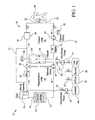
- a system 10 for providing dialysis treatment to a patient needing same is illustrated.
- two loops are provided: a patient loop (a recirculating patient fluid flow path) 12 and a regeneration loop 14 (a recirculating dialysate fluid flow path).
- the patient loop 12 is used to dialyze the patient 16 with dialysate in a peritoneal dialysis embodiment.
- the regeneration loop 14 also contains dialysate and is used to regenerate the dialysate in the patient loop 12.
- Fig. 1 shows a single dialysate bag 18 for both the patient and regeneration loops 12 and 14; however, separate dialysate bags and/or fluid pumps could be individually used for the patient loop 12 and the regeneration loop 14.
- the patient loop 12 is fluidly connected to the patient 16 by a multi-lumen patient fluid connector 20 and catheter.
- the multi-lumen patient fluid connector 20 can have, for example, a single housing 70 having more than one separate lumen 72 (to patient lumen) and 74 (from patient lumen), or separate housings each having one of the lumens 72 and 74.
- the multi-lumen patient fluid connector 20 can be connected to a dual lumen catheter 22 (illustrated in Fig.1 ), such as a catheter disclosed in co-pending U.S. patent application serial number 09/689,508 , titled "Peritoneal Dialysis Catheters," or other multi-fluid path patient access.
- the dual lumen catheter 22 is implanted in the patient 16 and provides fluid flow access to the patient's peritoneal cavity.
- Two separate lumens 72 and 74 of the multi-lumen patient connector 20 are fluidly connected to separate lumens (not illustrated) of the dual lumen catheter 22.
- Fluid in the patient' loop 12 can continuously flow through the patient fluid connector 20 simultaneously and continuously in multiple directions, e.g. two different directions, into and out of the catheter 22 and the patient 16.
- the multi-lumen patient fluid connector 20 is described in further detail below in Fig. 2 .
- the patient loop 12 can be fluidly connected to the patient by any device or devices that provides for fluid to simultaneously flow into and out of the patient.
- the patient loop 12 can be connected to the dual lumen catheter to two single lumen catheters.
- the patient loop 12 has a patient fluid pump 24 that pumps fluid through the patient loop 12.
- the fluid in the patient loop 12 is pumped from the patient 16 (the patient's peritoneal cavity in a peritoneal dialysis embodiment) through the patient fluid connector 20, through a dialyzer 26, back through the patient fluid connector 20, and is returned to the patient 16.
- the spent dialysate (laden with waste and excess water) in the patient loop 12 existing from the patient 16 is cleansed or regenerated by passing through the dialyzer 26.
- the waste, such as urea, creatinine and excess water passes from the patient loop 12 across a dialyzer membrane 28 to the regeneration loop 14 to produce fresh dialysate exiting the dialyzer in the patient loop 12.
- the fresh dialysate is returned to the patient 16 for further dialysis treatment.
- the fluid in the patient loop 12 is continuously recirculated through the patient loop 12 by the patient pump 24.
- the dialyzer 26 provides a sterile independent barrier between the patient loop 12 and the regeneration loop 14.
- Existing dialyzers used for dialysis therapy are suitable for use with the present invention, for example.
- the membrane 28 referred to in the dialyzer 26 includes any suitable filter material, such as hollow dialyzer fibers.
- the regeneration loop 14 removes the waste and excess water from the patient loop 12.
- a fluid pump 30, pumps dialysate fluid in the regeneration loop 14 continuously to recirculate the dialysate through the loop 14.
- the dialysate fluid pump 30 pumps the dialysate from the dialyzer 26, through a sorbent cartridge 32, and back to the dialyzer 26.
- the fluid in the regeneration loop 14 flows past a side of the dialyzer membrane 28 opposite the side of the membrane 28 having the fluid in the patient loop 12.
- the regeneration loop 14 provides for balanced fluid flow through the dialyser 26 by providing balance chambers. Equal flow dialysate fluid pumps (30) may also be provided.
- waste and excess water passes from the fluid in the patient loop 12, across the dialyzer membrane 28, to the fluid in the regeneration loop 14.
- the transfer across the dialyzer membrane 28 occurs at least in part due to diffusion and concentration gradients across the membrane 28.
- the system 10 in an embodiment maintains a lower fluid pressure in the regeneration loop 14 relative to the patient loop 12. That is, there is a transmembrane pressure ("TMP") across the dialyzer membrane 28.
- TMP transmembrane pressure
- the fluid pressure differential draws fluid from the patient loop 12, across the dialyzer membrane 28, to the regeneration loop 14.
- This fluid pressure differential can be maintained by removing fluid from the regeneration loop 14, for instance, by using the ultrafiltrate pump 19 to drain some of the fluid in the regeneration loop 14.
- the amount or rate of fluid removed from the regeneration loop 14 by the ultrafiltrate pump 19 determines the amount or rate of fluid transferring from the patient loop 12, across the dialyzer membrane 28, to the regeneration loop 14. This amount or rate equals the amount or rate of fluid removed from the patient 16 to the patient loop 12.
- a sorbent cartridge or container 32 includes materials that absorb particular compounds from the dialysate. For example, certain sorbents within the sorbent cartridge 32 may absorb uremic toxins, such as urea, creatinine, uric acid, and other metabolism by-products. By removing these undesirable waste material, the sorbent cartridge 32 at least partially regenerates the dialysate.
- the sorbent cartridge 32 includes a body having a fluid inlet 34 and a fluid outlet 36.
- One sorbent cartridge 32 contains four layers of materials, including a first layer of urease, a second layer of zirconium phosphate, a third layer of zirconium oxide and a fourth layer of carbon.
- the interior of the cartridge 32 is constructed and arranged so that the fluid entering the interior from the inlet 34 flows (preferably upward and Uniformly) through the first layer, the second layer, the third layer, the fourth layer and finally through the outlet 36.
- the sorbent cartridge 32 can also use materials that selectively remove certain solutes from the dialysate.
- the selective materials can include a binder or reactive sorbent material capable of selectively removing urea, a binder or reactive sorbent material capable of selectively removing phosphate and/or the like.
- the use of materials capable of selective removal of solutes, particularly urea enhances the cleaning efficiency of the system of the present invention such that the amount of dialysate necessary for effective treatment can be minimized.
- the materials that can selectively remove solutes from solution can include a variety of suitable and different materials including, for example, polymeric materials that are capable of removing nitrogen-containing compounds, such as urea, creatinine, other like metabolic waste and/or the like in solution.
- these types of materials contain a functional group(s) that chemically binds with urea or other like solutes.
- U.S. Patent Nos. 3,933,753 and 4,012,317 disclose alkenylaromatic polymers containing phenylglyoxal that can function to chemically bind urea.
- the phenylglyoxal polymeric material is made via acetylation performed in, for example, nitrobenzene followed by halogenation of the acetyl group and treatment with dimethylsulfoxide as disclosed in U.S. Patent Nos. 3,933,753 and 4,012,317 .
- Another example of a polymeric material that is capable of selectively removing solutes, such as urea, from solution includes polymeric materials that contain a tricarbonyl functionality commonly known as ninhydrin as disclosed in U.S. Patent No. 4,897,200 .
- the present system can include any suitable type of material or combinations thereof to selectively remove solutes, such as urea, from solution as previously discussed.
- the sorbent cartridge 32 may also modify the dialysate in the regeneration loop 14 in other ways.
- the materials in the sorbent cartridge 32 mentioned above or additional materials added to the cartridge 32 may modify the pH of the fluid passing through the cartridge 32.
- the pH of the dialysate in the regeneration loop 14 is modified as needed to maintain a physiologic level.
- One sorbent cartridge 32 is described in further detail in a U.S. patent application titled “Method and Composition for Removing Uremic Toxins in Dialysis Processes," Serial Number 09/990,673 .
- the sorbent partridge 32 can also include a number of components in addition to the sorbent materials capable of removing solutes from the dialysate.
- the cleaning cartridge may have the capability to remove all or a portion of electrolytes, such as sodium, potassium, or the like, from the dialysate solution. In this case, an additional source of electrolytes in solution may be needed to replenish the dialysate after it has been cleaned.
- the cartridge may also be configured to release bicarbonate or the like into the system depending on the type of sorbent material used. This can facilitate pH regulation of the dialysate. As necessary, the cartridge may be filtered to prevent proteins, particulate matter or like constituents from leaching or exiting from the cartridge and into the dialysate.
- Ultrafiltrate (excess water) removed from the patient 16 can be removed from the dialysis system 10 by training the ultrafiltrate to a drain bag 38 or other drain means.
- the ultrafiltrate pump 19 removes fluid from the regeneration loop 14 at the exit end of the dialyzer 26 through valves 40 and 42 to the drain bag 38, wherein the fluid contains the waste and excess water removed from the patient loop 12 by the dialyzer 26.
- the drain pump 19 can remove fluid from the regeneration loop 14 continuously or intermittently (e.g., batch operation), as desired.
- the dialysis solution in the regeneration loop 14 is removed from the system along with the ultrafiltrate. Accordingly, a dialysate concentrate is provided in a concentrate container 44 to supply necessary compounds to the regeneration loop 14. The concentrate from the container 44 mixes with the dialysate in the regeneration loop 14 and adds the compounds to the dialysate.
- the concentrate in an embodiment also includes other components that are provided to the patient 16, for example, electrolytes.
- a concentrate pump 46 and a valve 48 are provided to selectively pump the concentrate from the concentrate container 44 to the regeneration loop 14. The concentrate contributes to the regeneration of the dialysis solution in the regeneration loop 14.
- the various fluid pumps can be controlled by a computer, processor, or microprocessor, collectively referred to herein as a "controller” (not illustrated), to pump their respective fluids intermittently, if desired.
- the dialysis system 10 in an embodiment is a closed, sterile system. Air, moisture and fluids from the environment around the dialysis system 10 cannot enter into the patient loop 12 or the regeneration loop 14.
- the dialysis system 10 does permit fluids (such as ultrafiltrate) and air to exit the fluid loops 12, 14 and fluids (such as concentrate) to be added to the fluid loops 12, 14 under controlled circumstances.
- the dialysis system 10 is designed to prevent uncontrolled contact of the patient and the regeneration loops 12 and 14 with the surrounding environment.
- Fig. 1 schematically shows an example of an gas separator 50 in the dialysis system 10.
- gas is used herein to include gasses in general, including air, carbon dioxide (“CO 2 ”) and any other type of gas that can become entrained in fluid loops 12 and 14.
- the regeneration fluid loops 12 and 14 can accumulate air for various reasons.
- the fluid loops 12 and 14 may contain air prior to priming the system 10 with fluid or the storage containers may introduce air into the fluid loops 12 and 14.
- the sorbent cartridge 32 may produce CO 2 and introduce the CO 2 gas into the loops 12 and 14.
- the patient 16 can also produce certain gasses, which become entrained in the dialysate and enter the loops 12 and 14.
- the gas separator 50 removes entrained gas from the fluid in the regeneration loop 14 and vents the gas to outside of the dialysis system 10. In this manner, gas is purged from the regeneration loop 14.
- the gas separator 50 includes a one-way vent, i.e., it permits gas to vent from the fluid loops 12 and 14 to the atmosphere but prevents gas outside of the fluid loops 12 and 14 from entering into the loops.
- the gas separator 50 and the sorbent cartridge 32 of Fig. 1 are combined into a single device 102.
- One example of an gas separator 50/sorbant cartridge 32 combination is shown in the patent application titled “Method and Composition for Removing Uremic Toxins in Dialysis Processes," Serial Number 09/990,673, mentioned above.
- the gas separator 50 can be a separate system component or incorporated into system components other than the sorbent cartridge 32.
- an additional gas separator (not illustrated) can be provided in the patient loop 12, which vents to the atmosphere.
- the gas can be removed from the patient loop 12, fed to the gas separator 50 in the regeneration loop 14, e.g., via line 51, and vented to the atmosphere.
- one or more gas sensor(s) 52 are provided at desired locations along the patient loop and/or the regeneration loop 14 to detect gas in the system 10.
- gas sensor 52 electrically connect or are otherwise in communication with the system controller, which monitors gas content in the loops 12 and 14.
- the controller can control the system to perform any desired function in response to the gas, such as, stopping fluid flow, changing the direction of fluid flow, or removing the gas.
- the gas separator 50 can be any suitable device, which separates gas from fluid known to those of skill in the art. Gas separators, such as the separator 50, can be used which separate and vent the gas without being controlled by the system controller. In an embodiment, the gas separator 50 absorbs the gas rather than venting it to the atmosphere as illustrated.
- the dialysis system 10 contains a fluid heater 54, shown schematically in Fig. 1 .
- the fluid heater 54 heats the fluid in the patient loop 12 to a desired temperature for supplying the fluid to the patient 16.
- the fluid heater 54 is an in-line heater (continuous flow heater) that heats the fluid to the desired temperature as the fluid flows continuously past the heater 54.
- heaters other than in-line heaters can be used, for example, bulk heaters.
- the fluid heater 54 is shown in Fig. 1 in the patient loop 12 at the fluid supply to the patient 16. However, the fluid heater 54 can be positioned at other locations in the patient loop 12 and the regeneration loop 14, if desired. In another embodiment, one or both of the loops 12 and 14 include one or multiple heaters 54.
- the fluid heater 54 is a dual heater, including an infrared heater 56 and a plate heater 58.
- An example of such a dual heater 54 is disclosed in a patent application entitled, "Medical Fluid Heater Using Radiant Energy," Serial Number 10/051.609.
- Both the infrared heater 56 and the plate heater 58 are in-line heaters that heat the medical fluid that flows continnously past the heaters 56, 58.
- the radiant energy or infrared heater 56 emits infrared energy that is directed to and absorbed by the fluid in the patient loop 12, thereby heating the fluid.
- the radiant energy or infrared heater 56 is a primary or high capacity heater which can heat a relatively large volume of cold fluid to a desired temperature in a short period of time.
- the plate heater 58 is a secondary or maintenance heater which has a relatively lower heating capacity relative to the infrared heater 56.
- the plate heater 58 uses electrical resistance to increase the temperature of a plate that in turn heats the fluid flowing near the plate.
- the heater 54 which includes both high and low capacity heaters, provides an efficient heater design that accommodates various fluid heating requirements.
- the radiant or infrared heater 56 is particularly useful for quickly heating cool dialysate (high heat energy demand) that is supplied to the dialysis system 10, such as at the initial system fill or if there is severe heat loss during dialysis treatment.
- the temperature of the dialysate at initial system fill can be quite low, such as 5°C to 10°C if the fluid is stored in cold ambient temperature.
- the plate heater 58 is particularly useful to maintain a desired temperature (lower heat energy demand) of the fluid being supplied to the patient, e.g., due to a normal amount of heat loss during dialysis treatment.
- the infrared heater 56 provides for the high heat demand in a small amount of fluid exposure space, while the plate heater 58 provides for maintenance heat demand and requires a lesser amount, of input energy compared to the infrared or radiant heater 56.
- the heating capacity of the heater 54 is increased if both the infrared and plate heaters 56 and 58 are used together to heat the fluid.
- the infrared heater 56 and the plate heater 58 can be arranged in various configurations relative to each other.
- the heaters 56 and 58 in an embodiment are arranged so that the fluid passes by the heaters sequentially (e.g., first the radiant or infrared heater and then the plate heater). In another embodiment, the fluid passes by the heaters simultaneously (both heaters at the same time) or in the reverse order.
- the fluid flow path past the heaters 56 and 58 can be a common flow path for both heaters 56 and 58 or include independent flow paths for each heater 56 and 58.
- radiant or infrared electrical resistance heating other types of heating such as convective, inductive, microwave and radio frequency (“RF”) heating may be used.
- RF radio frequency
- temperature sensors are provided at desired locations along one or both of the patient loop 12 and the regeneration loop 14.
- the temperature sensors monitor various fluid temperatures and are connected to the system controller to control the fluid temperatures with the heater 54.
- the system 10 in an embodiment, can include separate temperature sensors for each heater so that each heater can be controlled individually.
- the dialysis system 10 in an embodiment also includes various other sensors to monitor various parameters.
- fluid pressure sensors 60 and 62 are provided in the patient loop 12 of Fig. 1 .
- the fluid pressure sensors 60 and 62 electrically couple to or otherwise communicate with the controller to provide a signal that indicates the respective fluid pressure at that location.
- the controller operates the fluid pumps and valves to obtain and maintain desired fluid pressures in the loop 12 running to and from the patient 16.
- the pressure sensors 60 and 62 are non-invasive pressure sensors. That is, the pressure sensors 60 and 62 do not physically contact (and possibly contaminate) the medical fluid or dialysate.
- the pressure sensors 60 and 62 measure the medical fluid pressure and help to maintain a steady flow within the closed fluid system.
- other fluid devices such as flow rate sensors, pressure gauges, flowmeters, or pressure regulators, which are not illustrated Fig. 1 , may be provided in any suitable quantity and at any desired location within either or both of the patient loop 12 and the regeneration loop 14.
- the system 10 includes an ammonia sensor 64.
- the ammonia sensor 64 measures the concentration of ammonia (NH3) and/or ammonium (NH4) in the fluid.
- Ammonia and ammonium are produced by the regeneration sorbent cartridge 32 as a by-product of the urea catalysis urease.
- the ammonia and ammonium are normally removed by a cation exchanger in the sorbent cartridge 32.
- the dialysis system 10 monitors the fluid for ammonia/ammonium concentrations with the sensor 64 to confirm that the ammonia and ammonium are being removed and remain below safe threshold levels for the patient 16.
- the total ammonia and ammonium in solution is primarily determined by three parameters: ammonia or ammonium, pH, and solution temperature. By measuring these parameters (or adjusting a parameter, such as adjusting the pH to a desired level), the total amount of ammonia and/or ammonium in the dialysate can be determined.
- the sensor 64 determines the total ammonia and ammonium content of an aqueous solution.
- the sensor 64 includes a hydrophobic ammonia sensing membrane, a pH indicator or conditioner, a temperature sensor and an optical sensor-
- An algorithm stored in the controller calculates the combined ammonia and ammonium content from the three parameters (e.g., NH3, pH and temperature).
- the ammonia gas which is highly soluble in water, is quantified by the hydrophobic sensing membrane that changes color based on the quantity of ammonia gas diffused into it
- a multi-wavelength optical sensor continuously measures the membrane color through a transparent window. The sensor 64 achieves a non-intrusive measurement by the using the optical sensor to monitor color changes in the disposable membrane placed inside the fluid path.
- the dialysis system 10 also includes one or more fluid flow measurement devices on volume sensors 66 that measure the volume of the medical fluid pumped either intermittently or cumulatively through one or both of the loops 12 and 14.
- the fluid flow measurement device 66 measures the amount of fluid supplied to the patient 16 by the patient loop 12.
- the regeneration loop 14 and/or the ultrafiltrate drain line employ one or more fluid flow measurement devices 66 to measure the amount of ultrafiltrate removed from the patient 16.
- Various types of fluid volume measurement or flowrate devices can be used with the dialysis system 10, such as orifice plates, mass flow meters or other flow measuring devices known to those of skill in the art.
- Fig. 1 schematically illustrates one embodiment of a flow measurement device or volume sensing device 66, which includes a capacitance sensor that measures the volume of fluid pumped through a chamber, such as a pump chamber (dotted lines designating the device 66 shown encircling the pumps 19, 24 and 30).
- the capacitive fluid sensor 66 is disclosed in greater detail in the patent application entitled, "Capacitance Fluid Volume Measurement,” Serial Number 10/054,487.
- the capacitance between the plates changes proportionally according to the function 1 / (R x V), wherein R is a know resistance and V is the voltage measured across the capacitor plates.
- the sensor cooperates with the pump chamber.
- the pump chamber in an embodiment includes shells or walls defining a fixed and known volume and a pair of flexible membranes operating between the shells, which expand to fill with fluid and contract to discharge fluid.
- the capacitance sensor 66 includes capacitor plates disposed on opposite sides of the pump chamber. As the volume of fluid in the chamber or fluid pump changes (i.e., the pump chamber fills or empties), the dielectric property of the varying fluids between the capacitance plates changes. For example, the combined dielectric constant of dialysate and air changes as dialysate replaces air (or air replaces dialysate) within shells of the constant volume chamber.
- This change in the overall dielectric constant affects a change in the capacitance between the two plates, which causes a change in voltage across the capacitance plates, wherein the change in voltage can be sensed by a voltage sensing device.
- the controller monitors the change in voltage by the voltage sensing. device and correlates (after a calibration of the sensor) the capacitance change to an amount of fluid pumped through the chamber.
- the volume of the chamber of the pump chamber can vary, e.g., by movement of one or both the shells of the chamber.
- the capacitance between the capacitor plates changes due to a changing distance d between the plates and/or a changing surface area S of one or more of the plates, wherein the dielectric constant k is static because only one fluid resides at all times between the capacitor plates.
- the capacitance C between the capacitor plates changes based on any combination or all three of a change in dielectric constant k, distance d and surface area S.
- the controller collects a multitude of voltage signals from capacitance changes from sensor 66 due to a plurality of chamber fill and drain cycles, wherein the controller calculates a total volume of medical fluid pumped over a length of time or number of pump cycles.
- the capacitance sensor 66 monitors the medical fluid, e.g., dialysate, flow into or from the pump chamber on a real time basis, and in a non-invasive manner.
- the capacitance sensor 66 enables the dialysis system 10 to maintain the volume of fluid that is provided to the patient 16 at desirable amounts and flow rates. Maintaining the fluid flow to the patient 16 within desired levels is particularly advantageous for peritoneal dialysis therapies.
- Physiologic control such as sensing and/or adjusting parameters of the fluids, can take place at various locations in the dialysis system 10, including the patient loop 12 and the regeneration loop 14.
- the sorbent cartridge 32 may include a pH sensor that adjusts the fluid in the regeneration loop 14, which then adjusts the fluid in the patient loop 12 via the dialyzer to be at a desired physiologic level.
- the dual lumen connector 20 includes a housing 70 having a lumen 72 for providing fluid to the patient lumen and a separate lumen 74 to remove fluid from the patient. Separate housings each having one of the lumens 72 and 74 may be provided.
- the patient inflow lumen 72 connects to a patient inflow tube 76 of the patient loop 12.
- the patient outflow lumen 74 connects to a patient outflow tube 78 of the patient loop 12.
- a removable end cap 80 is provided to seal a cavity 82 defined by the housing 70.
- the cavity 82 surrounds or abuts the lumens 72 and 74 and provides a connection area for the dual lumen catheter 22 ( Fig. 1 ) to insert into the cavity 82 and mate with the lumens 72 and 74.
- the housing 70, lumens 72 and 74 and the end cap 80 in an embodiment are made of any material suitable for medical applications, such as plastic for example.
- one of the lumens e.g., the patient inflow lumen 72 extends further into the cavity 82 than the other lumen, which helps facilitate mating of the connector 20 to the catheter 22.
- both lumens 72 and 74 extend into the cavity 82 the same or different distance.
- the dialysis system 10, particularly the patient loop 12, can be primed, e.g., filled, with the end cap 80 in sealing engagement with the housing 70.
- the narrows 84 and 86 figuratively illustrate the recirculating fluid flow through the dual lumen connector 20.
- the system 10 can therefore run without a fluid connection to the patient.
- the system 10 may include a patient by-pass line between the patient inflow and outflow tubes 76, 78 to allow fluid flow through the patient loop 12 while by-passing the patient 16.
- the end cap 80 is removed, e.g., pulled off or unscrewed, to expose the cavity 82 and the patient inflow and outflow lumens 72 and 74, respectively, for connection to the dual lumen catheter 22.
- the patient fluid loop 12 directly connects to the dual lumen catheter 22 or to two separate single lumen catheters.
- the connector 20 is adapted to connects to two separate single lumen catheters.
- two separate connector link single lumen catheters to incoming and outgoing lines of the patient fluids loop 12.
- the system 100 of Fig. 3 includes many of the same components as the system 10 of Fig. 1 .
- the system 100 includes two loops, a patient loop. 12 and a regeneration loop 14.
- the patient loop 12 passes dialysate to and from a patient 16.
- the patient loop 12 and regeneration loop 14 are initially filled and primed with dialysate from a dialysate bag 18.
- the patient loop 12 fluidly connects to the patient 16 by the multi-lumen patient fluid connector 20 described above in connection with Fig. 2 .
- the multi-lumen connector 20 connects to a dual lumen catheter 22.
- the system 100 includes multiple patient fluid pumps 24a and 24b. It has been found that using multiple pumps, such as the patient fluid pumps 24a and 24b, creates a steadier flow of fluid to and from the patent 16 within the patient loop 12. For example, fluid may be exiting the fluid pump 24a while the fluid pump 24b is filling with fluid. Balance chambers are provided to balance fluid flow.
- the system 100 includes the dialyzer 26 having the dialyzer membrane 28.
- the spent dialysate laden with waste and excess water in the patient fluid loop 12 is cleaned or regenerated when recirculated through the dialyzer 26.
- the waste passes from the patient loop 12 across the dialyzer membrane 28 to the regeneration loop 14.
- the fluid pumps 30, continuously pump the regenerating dialysate through the combination device 102, which includes the absorbent cartridge 32 and the gas separator 50.
- the system 100 includes dual dialysate fluid pumps 30 to provide balanced flow within the regeneration loop 14. That is, one of the fluid pumps 30 is being emptied of fluid while the other pump 30 is being filled with fluid.
- the system 100 can drain ultrafiltrate and other fluids into the drain bag 38.
- An ultrafiltrate pump 19 pumps the ultrafiltrate and fluids from the patient loop 12 or the regeneration loop 14, for example through valves 40 and 42, into the drain 38.
- the system 100 also provides the ability to collect fluid in a twenty-lour hour collection bag 39 for revaluation of the dialysis therapy.
- one of the patient fluid pumps 24a or 24b pulls dialysate fluid from either the dialysate bag or container 18 or the last bag 21.
- the last bag 21 includes a volume of fluid that is placed in the patient's peritoneal cavity just prior to the end of the dialysis treatment.
- the patient with the dialysate from the last bag 21 in the peritoneal cavity disconnects from the system 100 and is able to perform daily activities.
- the next dialysis therapy begins with draining the last bag from the patient.
- the system 100 includes a concentrate container 44, a concentrate pump 46 and valves 48.
- the concentrate pump 46 provides concentrate from the concentrate container 44 to the regeneration loop 14, for example into the fluid line exiting from the outlet 36 of the combination absorbent cartridge and vent 102.
- the concentrate container 44 supplies necessary compounds, such as electrolytes and osmotic agents, to the regeneration loop 14 of the system 100 to maintain the desired concentrations of those components.
- the system 100 regenerates dialysate through the regeneration loop 14 and does not require fluids from an outside source.
- the system 100 is completely closed to the outside.
- the systems of the present invention are thus "closed loop systems".
- the closed loop nature of the patient loop 12 and the regeneration loop 14 enables the loops to run continuously without absorbing or gathering outside contaminants.
- the closed loop systems of the present invention also maintain sterility by preventing contamination from the environment.
- the system 100 may generate gases over time, such as air and CO 2 .
- the system 100 provides a plurality of gas sensors 52 that detect the various gases that may be in the system 100.
- the gas sensors 52 are provided at an air separator which separates gas from the fluid in the patient loop 12.
- a gas separation line 51 feeds the separated gas from the patient loop 12 to the inlet side 34 of the combination absorbent cartridge and gas separator device 102.
- the gas is then purged out of the system 100 by the gas separator 50.
- the gas separator 50 maintains the closed loop structure of the system 100 by preventing contaminants from entering the system 100.
- the gas separator 50 can include a microbial filter which allows gas to exit the system 100, but prevents contaminants from entering the system 100.
- the gas from the patient loop 12 may be purged from the system 100 by a separate gas purge device at the patient loop 12.
- the gas sensors 52 in an embodiment, can send an electronic signal to the controller (not illustrated). When the controller detects gas, the controller causes one or more valves to open, wherein the gas from the loop 12 is fed to a one-way vent and purged from the system 100.
- the system 100 further includes the inline heater 54, which, in an embodiment, includes an infrared or radiant heater 56 and a plate heater 58 as described above.
- the heater 54 has an air separator which allows air to exit port 59 on be purged from the system.
- the system 100 further includes an orifice device 61 that stabilizes the differential pressure in the dialyzer 26 across the membrane 28. That is, the orifice device 61 can restrict the flow in the patient loop 12 to create a pressure differential between the patient side and regeneration side of the dialyzer 26. The pressure gradient or differential occurs across the membrane 28 in which the patient loop 12 having a higher fluid pressure than the regeneration loop 14.
- the orifice device can be a fixed or variable flow restriction and can provide a fixed or variable pressure differential.
- the orifice device 61 can be electrically coupled to and operated by the controller, which can activate, e.g., open or close the orifice device as necessary.
- the pressure differential across the membrane 28 (higher pressure in the patient loop 12 and lower pressure in the regeneration loop 14) created by the orifice 61 assists in maintaining a greater pressure in the regeneration loop 14 relative to atmosphere pressure external to the system 100.
- the positive pressure in the regeneration loop 14 relative to the external atmosphere pressure aids in ensuring that external air is not pulled from the surrounding environment through the air vent 50 into the regeneration loop 14, i.e., air can only exit the system 100 and not enter into the system 100. Accordingly, the orifice 61 contributes to the closed loop nature of the system 100.
- the system 100 provides a number of temperature sensors, such as sensors 63, 65 and 67, which monitor temperatures at various points within the patient loop 12.
- the controller uses the sensed temperatures to maintain a desired temperature within the patient loop 12.
- the temperature sensor 63 is located at or on the heater 54, which enables the system 100 to sense a temperature at a point very close to the constituent heaters 56 and 58, and to control the heaters 56, 58.
- the system 100 further includes one or more pressure sensors 60 and 62, which reside at various points along the patient fluid loop 12.
- the pressure sensors 60 and 62 can be used to prevent excessive positive or negative pressures from being applied to the patient.
- the pressure within the system can be controlled by, e.g., activation of the patient fluid pumps 24a, 24b.
- the system 100 also monitors the absorbent cartridge 32 with an ammonia/ammonium sensor.
- Sample fluid exiting the absorbent cartridge 32 can be directed through a pH adjuster 71 to force the ammonia/ammonium equilibrium balance to a particular level.
- the amount of ammonia and/or ammonium in the sample fluid is measured by a sensor 73. Accordingly, the effectiveness of the cartridge 32 to remove ammonia/ammonium after conversion from urea can be monitored.
- the concentration of ammonia and/or ammonium reaches a threshold level, the system can produce a signal, or take other action such as shutting down, that indicates the cartridge 32 needs to be replaced.
- system 100 can monitor other fluid parameters and take appropriate action, as desired.
- sample fluid can be taken at any desired location in the system 100.
- fluids in the patient and regeneration loops 12, 14 can be tested or monitored directly rather than taking samples.
- the system 100 also includes fluid volume sensors 66 which in an embodiment are capacitance sensors that sense a change in capacitance occurring between two capacitor plates.
- the capacitor plates surround the pumps 24 of the patient loop 12, the pumps 30 of the regeneration loop 14 and the pumps leading to the fluid containers.
- Each of the pumps 24a, 24b, pump 30, pump 19 and pump 46 can be provided with the capacitance volume sensor 66.
- Each of the sensors 66 sends a discrete signal to the controller (not illustrated), which measures and monitors the volume of fluid flowing through the pump chambers of the respective pumps. In other embodiments, any suitable fluid volume measurement device can be used.
- the system 110 of Fig. 4 is similar to the system 100 of the Fig. 3 and is a closed loop system.
- the system 110 includes various components of the system 100 described previously.
- the system 110 has a regeneration loop 14 which has a pair of balanced dialysate fluid pumps created by a pair of chambers 75 that operate with the pumps 30.
- Each balance chamber 75 includes a pair of chambers separated by a membrane.
- the membrane is forced toward the other chamber, which forces fluid out of that chamber. In this way, the membrane acts to balance the flow of the dialysate fluid within the regeneration loop 14, so that there is no net flow of fluid across the dialyzer membrane except for the flow needed to replace the fluid removed by the ultrafiltrate pump 19.
- the gas separator 50 is independent of the sorbent cartridge 32.
- the gas separator 50 accepts gas through a vent line 51 that runs from the exit port 59 of the heater 54 in the patient fluid loop 12.
- One or more gas sensors 52 monitor gas in the vent line 51 as illustrated.
- a dialysis system having a disposable cassette 120 is illustrated.
- the pumps 30 of system 120 draw fluid from accumulators A4 and A6 and discharge into accumulators A3 and A5.
- Accumulators A3 to A6 smoothen the dialysate flow by dampening pressure fluctuations during pumping.
- much of the flow logic and at least parts of the flow devices described above are provided in the disposable cassette 120.
- the cassette 120 in an embodiment, has a rigid plastic body 122 with various fluid flow channels and fluid chambers defined in the body 122.
- a flexible membrane is bonded to the front side of the cassette body 122 shown in Fig. 5 .
- the membrane covers the fluids channels and chambers and is sealed to the body 122 around the channels and chambers. Accordingly, the membrane forms a wall of the fluid flow paths and fluid chambers. Similarly, the back side of the cassette body 122 may also be covered with a membrane.
- the body 122 in an embodiment, is approximately 30cms (12 inches hight), 20cms (eight inches) wide, and 2.5cms (one inch) deep.
- the flow components and flow lines defined by the body 122 fluidly connect to other system components.
- pump actuators, valve actuators, sensors and other system components may interface with the cassette 120.
- the body 122 provides a portion of the closed patient and regeneration loops 12 and 14.
- the dual lumen catheter 22 that inserts into the peritoneal cavity of the patient 16 connects to the dual lumen connector 20 outside of the body 122 of the disposable cassette 120.
- the patient loop 12 extends from an exit port 124 of the dialyzer 26 to a valve chamber 126 defined by the body 122.
- the patient fluid loop 12 includes a series of manifolds and fluid flow paths that fluidly connect to the patient fluid pump(s) 24.
- the patient fluid pump 24 pumps the dialysate through the patient 16 and into an inlet 128 of the dialyzer 26.
- the patient fluid loop 12 also connects via pathways defined by the body 122 of the disposable cassette 120 to various medical fluid bags.
- the dialysate fluid bag 18, which is maintained outside of the disposable cassette 120 fluidly connects to a line 130 leading to the patient fluid loop 12.
- the last bag 21 also connects via a line defined by the body 122 to the line 130 that fluidly communicates with the patient fluid loop 12.
- the line 130 defined by the body 122 also fluidly communicates with the ultrafiltrate drain 38.
- the body 122 of the disposable cassette 120 also defines chambers for the concentrate pump 46 and the ultrafiltrate pump 19.
- the concentrate pump 46 fluidly connects to an external concentrate bag 44.
- the twenty-four hour collection bag 39 described above fluidly connects along with the drain 38 to a fluid line defined by the body 122 that runs to the ultrafiltrate pump 19.
- the disposable cassette 120 provides fluid flow paths and defines chambers and other types of fluid orifices for the fluid flow components described above. Specifically, the body 122 of the disposable cassette 120 defines a patient fluid pump chamber 24 and dialysate fluid pump chambers 30.
- the disposable cassette 120 mounts to a separate non-disposable housing that includes the mechanical workings of the flow components, such as the pumps.
- the pump chambers are bounded on one side by a flexible membrane (not illustrated) that is positioned adjacent to and driven by the pump plungers of the non-disposable housing.
- At least one side of the cassette 120 is covered with the flexible, e.g., plastic membrane (not illustrated).
- the disposable cassette 120 plugs into a cavity or portion of the non-disposable housing (not illustrated).
- the housing provides the actuators for each of the pumps herein described, e.g., the patient pumps 24, the dialysate pumps 30, the ultrafiltrate pump 19 and the concentrate pump 46.
- the housing also provides the actuators for the various valve chambers defined by the body 122 of the cassette 120, e.g., valve chamber 126.
- the more expensive mechanical and electromechanical pieces of the flow components, e.g., the pump actuators and valve actuators, are kept and reused in the housing.
- the disposable cassette 120 provides sterile, disposable fluid pathways, such as the pump chambers and the valve chambers.
- the actuators of the non-disposable housing press against the flexible plastic membrane at the pump chambers and valve chambers to force or allow fluid through the system.
- the membrane returns to its normal shape and no longer exerts a force on the fluid within the pump chamber.
- the pump chamber fills with fluid as the membrane is drawn back. Also, the membrane can be positively drawn back by, for example, the pump actuator or vacuum pressure. The pump has thus made a cycle.
- the body 122 of the disposable cassette 120 also defines at least a portion of a mounting area for housing the ammonia, ammonium or pH sensors or adjustors.
- the disposable cassette 120 defines an area for housing the pH adjustor 71 and a disposable colormetric membrane (which changes color based on the ammonia/ammonium concentration) of the ammonia/ammonium sensor 73, wherein the fluid within the body 122 of the cassette 120 can fluidly communicate with the sensor.
- the optical color reader of the ammonia/ammonium sensory 73 is disposed in the non-disposable housing (not illustrated), wherein the sensor can receive electrical power as needed. If a pH sensor is used instead of the pH adjustor 71, a reusable portion of the pH sensor can also be located in the housing.
- the housing also provides the in-line heater 54 and in an embodiment provides one of either the radiant heater 56 and the plate heater 58, which is described in detail in the patent application entitled, “Medical Fluid Heater Using Radiant Energy,” Serial Number 10/051,609, mentioned above. Further, the housing provides one of the capacitor plates of the fluid volume sensor 66 beneath one or more of the pump actuators, as described in detail in the patent application entitled, “Capacitance Fluid Volume Measurement,” Serial Number 10/054,487, mention above.
- the cassette 120 has an in-line heating fluid heating path 123 for heating the fluid.
- the fluid in the heating path 123 is heated by a heater external to the cassette.
- the cassette 120 also has one or more gas separators 125 which separate gas from fluid in the cassette 120.
- the gas separators 125 feed the separated gas through a line 127 to a vent 129.
- the closed loop system of the present invention enables at least one waste component to pass through the membrane 28 of the dialyzer. 26 from the patient fluid loop 12 to the regeneration loop 14.
- the patient loop 12 extending outside of the body 122 fluidly connects to a valve chamber 132 defined by the body 122.
- the regeneration loop 14 includes manifold sections defined by the body 122 and leads to pump chambers 30.
- the closed loop system prevents air or other fluids from entering the system.
- the pump chambers 30 fluidly communicate with the sorbent chemical cartridge 32 and the gas separator 50 of the combined device 102.
- the regeneration loop 14 extends from the outlet 36 of the combined device 102 and returns to the body 122 of the disposable cassette 120 through the valve chamber 134. From the valve chamber 134, the regenerated dialysate is pumped through the pump chambers 30 and into the manifold system defined by the body 122.
- FIG. 6 another closed loop system having another disposable cassette 140 is illustrated.
- This embodiment of the disposable cassette 140 includes many of the same flow components and flow chambers as the cassette 120 of Fig. 5 .
- the cassette 140 only includes a single regeneration pump body 30.
- the cassette 140 in general, is less complicated than the cassette 120 and illustrates that the disposable cassettes may be adapted for different embodiments of the closed loop dialysate regeneration systems described herein.
- the cassette 140 is covered with a flexible, e.g., plastic membrane (not illustrated).
- the disposable cassette 140 plugs into a non-disposable housing (not illustrated) that provides the actuators for the various pumps, e.g., the patient pump 24, the dialysate pump 30, the ultrafiltrate pump 19 and the concentrate pump 46.
- the housing also provides the actuators for the various valve chambers defined by the body 122 of the cassette 140.
- the more expensive mechanical and electromechanical pieces of the flow components, e.g., the pump actuators are again kept and reused in the housing. As described above, the actuators press against the flexible plastic membrane at the pump chambers to force fluid through the system.
- the disposable cassette 120 or 140 in combination with certain external devices such as the dialyzer 26, sorbent cartridge and gas separator device 102 and the fill and drain bags, provides completely closed loop systems.
- the only make-up or additional fluid that the regeneration system uses is that of the concentrate from the concentrate bag 44, which seals to a device within the body 122 of the cassettes 120 and 140.
- fluids and air cannot enter the closed loop system.
- FIG. 7 a schematic diagram illustrates the different physical components of a disposable set of the regeneration system of the present invention.
- the disposable set is intended to be used for a single dialysis therapy and then discarded. Another disposable set is used for the next dialysis therapy.
- Each of the above-described systems 10, 100 and 110 in an embodiment includes a disposable cassette, such as the cassette 120 or 140.
- the disposable cassette 120 or 140 provides a port 141 that connects to the concentrate bag 44 via a line 147.
- the cassette provides a port 142 that fluidly connects to the drain bag 38 via a line 148.
- the cassette provides a port 143 that fluidly connects to the last bag 21 via a line 149.
- the cassette defines a port 144 that fluidly connects to the dialysate bag 18 via a line 150.
- the cassette provides ports 145 and 146 that run to and from the dual lumen connector 20 via patient lines 151 and 152, respectively.
- each of the lines 147 to 152 are made of medical grade tubing, such as a flexible, sterile and inert plastic such as polyethylene, polystyrene, polypropylene or polyvinylchloride ("PVC").
- the bags and the lines are clear so that the patient or operator can see fluids traveling from the bags and through the lines to a cassette 120 or 140.
- the lines 147 to 152 connect to the ports 141 to 146 via any type of medical fluid connection known to those of skill in the art.
- the connections are quick-type connections that enable the patient or operator to easily remove the line from its mating port.
- the disposable cassette 120 or 140 includes at least one port 153 that fluidly connects to at least one outlet port 154 of the gas separator 50 or combination device 102.
- the disposable cassette 120 or 140 includes at least one port 155 that fluidly connects to at least one inlet port 156 of the sorbent cartridge 32 or combination device 102.
- the lines connecting the disposable cassette 120 or 140 to the sorbent cartridge 32, gas separator 50 or combination device 102 including same are made of medical grade tubing, such as a flexible, sterile and inert plastic such as polyethylene, polystyrene, polypropylene or polyvinyl chloride.
- FIG. 8 an alternative closed loop regenerative system 160 is illustrated.
- the system 160 is shown schematically, however, the system 160 may employ the disposable set described above such as the disposable cassette, the fluid pumps, the various sensors, valves and controller.
- the system 160 includes a patient fluid loop 12 and a regeneration loop 14.
- dialysate When dialysate is removed from the peritoneal cavity of the patient 16, the solution passes through an activated charcoal and anion exchanger 162.
- the activated charcoal of the filter or exchanger 162 removes uric acid, creatinine, small molecular weight organics and middle molecules.
- the anion exchange column of the exchanger 162 removes phosphate.
- the solution exiting the filter or exchanger 162 enters a solution or dialysate bag 18.
- the dialysate entering the solution bag 18 has two possible places to exit. One possibility includes exiting the solution bag 18 from a port 163, entering a filter 166 and returning to the peritoneal cavity of the patient 16. Another possibility includes exiting the solution bag 18 at a port 165 and entering a nanofilter 164.
- the system 160 splits the dialysate fluid exiting the solution bag or container 18.
- the nanofilter 164 operates similar to the dialyzer 26 described above.
- the nanofilter 164 includes a membrane.
- the membrane of the nanofilter 164 rejects most electrolytes, i.e., allows most of the electrolytes to return to the solution bag.
- the nanofilter 164 filters most all of the urea and a small amount of sodium through the membrane and into a sorbent system cartridge 32, which is similar to the sorbent cartridges described above.
- the sorbent cartridge 32 as described above absorbs and the urea from the fluid that is able to permeate through the membrane of the nanofilter 164.
- a plurality of pumps are provided to individually circulate medical fluid or dialysate through the patient loop 12 and the regeneration loop 14.
- the pump or pumps that control the recirculation through the regeneration loop 14 are adapted to circulate the regenerating fluid at a different flow rate, i.e., much faster, than the flow rate of fluid pumped through the patient loop 12. It is believed that by using this method, the need for a concentration bag such as the concentration bags 44 described above would not be needed.
- the system 160 is a closed loop system that does not require any sort of make-up materials or any continuous source of outside fluid. The system 160 is therefore very adept at keeping air and other contaminants from entering the system.
- the a reverse osmosis membrane or an electrooxidation system replaces the sorbent cartridge 32.
- a reconstitution or concentration bag such as the concentration bag 44, is likely to be necessary.
- the regeneration loop 14 removes urea at a rate of approximately 50 to 80%.
- the dialysate returns to the peritoneal cavity of the patient 16 substantially free from uric acid, creatinine, small molecular weight organics and middle molecules.
- the nanofilter 164 can reject calcium magnesium at a rate of approximately 98% and glucose at a rate of approximately 80%.
- the permeate stream exiting the nanofilter 164 includes urea, approximately 70% sodium chloride and approximately 20% glucose. It should be appreciated that the system 160 is useful for performing continuous flow peritoneal dialysis.
- a system 170 is illustrated.
- Each of the previous systems 10, 100 and 110 of Figs. 1 , 3 and 4 , respectively, can be used for peritoneal dialysis or hemodialysis.
- each of the systems described above has been primarily described and illustrated using peritoneal dialysis, that is, the patient loop has been illustrated using a dialysis solution.
- the system 170 illustrates that the dual lumen catheter or two single lumen catheters can be replaced by a hemodialysis needle 171, which connects to the arm (or other suitable portion) of the patient 16 to withdraw blood through the hemodialysis needle 171.
- the system 170 illustrates that the patient's blood flows through the patient loop 12 while dialysate flows through the regeneration loop 14.
- the patient's blood flows along one side of the membrane 28 of the dialyzer 26, while the dialysate flows along the outside or other side of the membrane 28 of the dialyzer 26.
- the waste components and ultrafiltrate transfer from the patient's blood in the patient loop 12, through the membrane 28, into the dialysate in the regeneration loop 14.
- the system 170 includes a fixed volume recirculating regeneration loop 14 that dialyzes the patient fluid loop 12.
- a single pump 172 operates to remove the ultrafiltrate from the patient 16 to the ultrafiltrate container 38.
- the pump 172 adds dialysis fluid from the dialysis bag 18 or concentrate from the concentrate bag 44 to the regeneration loop 14.
- the concentrate can be metered into the dialysate of the regeneration loop 14 as a solid prior to or during therapy.
- the volume of dialysate fluid flowing through the regeneration loop 14 can be determined using an electronic balance 174 illustrated below the dialysate bags.
- the electronic balance 174 keeps track of the amount of dialysate that is supplied to the system during a priming of the system.
- the electronic balance 174 also monitors any additional dialysate added to the patient loop 12 during dialysis treatment
- the electronic balance 174 measures the amount of ultrafiltrate that is withdrawn from the system and the amount of the concentrate that is added from the concentrate bag 44.
- the system 170 removes ultrafiltrate by opening a valve chamber and transferring a known volume of the fluid into the ultrafiltrate bag 38.
- the removal of fluid creates a pressure differential across the membrane 28 of the dialyzer 26, which causes fluid to filter through the dialyzer membrane 28 and into the regeneration circuit 14.
- Sterile dialysate from a supply bag 18 is infused into the patient circuit 12 as required.
- Concentrate from the concentrate bag 44 can also be infused into the regenerating circuit 14 as needed.
- Pressure sensors 176 monitor and control the rate at which the system 170 draws ultrafiltrate into the container 38.
- Gas sensors 52 are used to prevent air from being delivered to the patient 16.
- a multi-analyte sensor 178 can be employed to monitor the concentration of electrolytes in the regenerated dialysate as well as the efficiency of the regeneration system in removing uremic toxins. The output of the multi-analyte sensor 178 controls the rate of reconstitution from the concentrate bag 44, the efficiency of the regeneration system and can detect the presence of a leak in the dialyzer.
- a vent 180 vents air that becomes trapped in the system or CO 2 that is generated by the absorbent cartridge 32.
- an automated valve that is provided integrally with the adsorbent cartridge 32 replaces the mechanical vent 180. integrally with the adsorbent cartridge 32 replaces the mechanical vent 180.
- the system 170 is illustrated as a hemodialysis system, the system 170 is easily converted to a peritoneal dialysis system by placing the catheter into the patient's peritoneal cavity and by running dialysate through the patient loop 12 as opposed to the patient's blood.
- the ultrafiltrate bag 38, the dialysate container 18 and the concentrate container 44 each fluidly connect to the regeneration loop 14 and the patient circuit is kept relatively simple.
- the system 170 is especially conducive for continuous flow of peritoneal dialysis, however, standard APD and TIDAL therapies could be performed in the system 170.
- a combined absorbent cartridge, pump and valve system is placed into a single container, e.g., a canister, cartridge or cassette 190.
- the combination container 190 is illustrated as housing the components specifically described in the system 170 of Figure 9 .
- the combination container 190 is adaptable to house the components of any of the above-described systems, namely, the systems 10, 100 and 110.
- the canister, cartridge or cassette is adaptable to be made of any material such as plastic or metal.
- the container 190 includes the adsorbent cartridge 32, which is configured as described above.
- the container includes the combination device 102 that provides the adsorbent cartridge 32 and the gas separator 50.
- the container 190 includes the pumps illustrated in Fig. 9 including the pump 172 that enables dialysate to be drawn from the dialysate bag 18 or concentrate to be drawn from the concentrate bag 44. Additionally, the pump 172 enables ultrafiltrate to be drained into the bag 38.
- the container 190 includes the multi-analyte sensor 178 and the gas sensor 52, as described in the system 170 of Fig. 9 .
- the container 190 also includes the mechanical or automated vent 180 described in the system 170.
- the only devices external to the container 190 are the dialysate bags and the hemodialysis needle 171 that is inserted in the patient's arm or other extremity to perform hemodialysis. Obviously, by the multi-lumen connector 20 and catheter 22 can replace the needle 171 to perform peritoneal dialysis.
- the cassette 190 When the container 190 is provided in the form of a disposable cassette, the cassette 190, like the cassettes 120 and 140 of Figs. 5 and 6 , is covered on at least one side with a flexible, e.g., plastic membrane (not illustrated).
- the disposable cassette 190 plugs into a non-disposable housing that provides the actuators for the various pumps, e.g, the patient pumps 24, the dialysate pumps 30, the ultrafatrate pump 19 and the concentrate pump 46.
- the more expensive mechanical and electromechanical pieces of the flow components, e.g., the pump actuators, are again kept and reused in the housing.
- the sorbent cartridge 32 and the gas vent 180 can be disposable.
Abstract
Description
- The present invention generally relates to peritoneal dialysis systems. More specifically, the present invention relates to regeneration peritoneal dialysis systems and continuous flow peritoneal dialysis systems.
- Due to disease, insult or other causes, a person's renal system can fail. In renal failure of any cause, there are several physiological derangements. The balance of water, minerals and the excretion of daily metabolic load is no longer possible in renal failure. During renal failure, toxic end products of nitrogen metabolism (urea, creatinine, uric acid, and others) can accumulate in blood and tissues.
- Kidney failure and reduced kidney function have been treated with dialysis. Dialysis removes waste, toxins and excess water from the body that would otherwise have been removed by normal functioning kidneys. Dialysis treatment for replacement of kidney functions is critical to many people because the treatment is life saving. One who has failed kidneys could not continue to live without replacing at least the filtration functions of the kidneys.
- Hemodialysis and peritoneal dialysis are two types of dialysis therapies commonly used to treat loss of kidney function. Hemodialysis treatment utilizes the patient's blood to remove waste, toxins and excess water from the patient. The patient is connected to a hemodialysis machine and the patient's blood is pumped through the machine. Catheters are inserted into the patient's veins and arteries to connect the blood flow to and from the hemodialysis machine. As blood passes through a dialyzer in the hemodialysis machine, the dialyzer removes the waste, toxins and excess water from the patient's blood and returns the blood to infuse back into the patient. A large amount of dialysate, for example about 120 liters, is used to dialyze the blood during a single hemodialysis therapy. The spent dialysate is then discarded. Hemodialysis treatment lasts several hours and is generally performed in a treatment center about three or four times per week.
- One type of hemodialysis therapy is regenerative hemodialysis. This therapy uses a hemodialysis system, which includes a cartridge for dialysate regeneration. One such cartridge is manufactured under the name REDY™ by Sorb Technology, Oklahoma City, Oklahoma. In this system, the dialysate fluid flow path must be properly cleaned before the hemodialysis machine can be used on another patient. Also, the dialysate fluid flow path is not a closed system, i.e., the dialysate fluid flow path is open to the atmosphere, such that oxygen from the atmosphere can contact fluid in the system and foster the growth of bacteria in same. Consequently, contamination of such a dialysis system can be a concern. Further, the dialysate fluid exiting the REDY™ cartridge is not suitable for peritoneal dialysis because the fluid is relatively acidic and not, therefore, physiologic. Moreover, this system requires the attention of medical personnel during therapy.
- Peritoneal dialysis utilizes a sterile, pyrogen free dialysis solution or "dialysate", which is infused into a patient's peritoneal cavity. The dialysate contacts the patient's peritoneal membrane in the peritoneal cavity. Waste, toxins and excess water pass from the patient's bloodstream through the peritoneal membrane and into the dialysate. The transfer of waste, toxins, and water from the bloodstream into the dialysate occurs due to diffusion and osmosis, i.e., an osmotic gradient occurs across the membrane. The spent dialysate drains from the patient's peritoneal cavity and removes the waste, toxins and excess water from the patient. This cycle is repeated on a semi-continuous or continuous basis.
- The various types of peritoneal dialysis therapies, including continuous ambulatory peritoneal dialysis ("CAPD") and automated peritoneal dialysis. CAPD is a manual dialysis treatment, in which the patient connects an implanted catheter to a drain and allows a spent dialysate fluid to drain from the peritoneal cavity. The patient then connects the catheter to a bag of fresh dialysate and manually infuses fresh dialysate through the catheter and into the patient's peritoneal cavity. The patient disconnects the catheter from the fresh dialysate bag and allows the dialysate to dwell within the cavity to transfer waste, toxins and excess water from the patient's bloodstream to the dialysate solution. After a dwell period, the patient repeats the manual dialysis procedure.
- In CAPD the patient performs several drain, fill, and dwell cycles during the day, for example, about four times per day. Each exchange or treatment cycle, which includes a drain, fill and dwell, takes about four hours. Manual peritoneal dialysis performed by the patient requires a significant amount of time and effort from the patient. This inconvenient procedure leaves ample room for improvement and therapy enhancements to improve patient quality of life.
- Automated peritoneal dialysis is similar to continuous peritoneal dialysis in that the dialysis treatment includes a drain, fill, and dwell cycle. However, a dialysis machine automatically performs three to four cycles of peritoneal dialysis treatment, typically overnight while the patient sleeps.
- With automated peritoneal dialysis, an automated dialysis machine fluidly connects to an implanted catheter. The automated dialysis machine also fluidly connects to a source or bag of fresh dialysate and to a fluid drain. The dialysis machine pumps spent dialysate from the peritoneal cavity, though the catheter, to the drain. The dialysis machine then pumps fresh dialysate from the dialysate source, through the catheter, and into the patient's peritoneal cavity. The automated machine allows the dialysate to dwell within the cavity so that the transfer of waste, toxins and excess water from the patient's bloodstream to the dialysate solution can take place. A computer controls the automated dialysis machine so that the dialysis treatment occurs automatically when the patient is connected to the dialysis machine, for example, when the patient sleeps. That is, the dialysis system automatically and sequentially pumps fluid into the peritoneal cavity, allows for dwell, pumps fluid out of the peritoneal cavity, and repeats the procedure.
- Several drain, fill, and dwell cycles will occur during the treatment. Also, a "last fill" is often used at the end of the automated dialysis treatment, which remains in the peritoneal cavity of the patient when the patient disconnects from the dialysis machine for the day. Automated peritoneal dialysis frees the patient from having to manually performing the drain, dwell, and fill steps. Automated dialysis can improve the patient's dialysis treatment and undoubtedly improves the patient's quality of life.
- So-called "continuous flow" peritoneal dialysis ("CFPD") systems that purport to provide continuous dialysate flow exist. However, these systems typically have a single pass fluid flow. That is, the dialysate flows into, through, and out of the peritoneal cavity one time before being sent to a drain. The "spent" dialysate (waste laden dialysate) from the patient collects in a drain bag, which is discarded, or runs into a household drain or other drain. Known CFPD systems, therefore, typically use a volume of disalysate one time and then discard it. That is, the systems have no ability to regenerate or reuse a quantity of dialysate.
- The effectiveness of existing peritoneal dialysis therapies, and existing systems which perform the therapies, depends upon the amount of dialysis fluid used. For example, typical peritoneal dialysis therapy requires about 4 to 6 exchanges of dialysate (drain, fill, dwell) with about 2 to 3 liters of dialysate for each exchange. Peritoneal dialysis is a daily therapy performed 7 days per week. As a consequence, 240 to 540 liters of fresh dialysate must be delivered to and stored at a patient's home each month. Increasing dialysate dosage to increase therapy effectiveness will necessitate even more dialysate).
- Ups-4,481,372 discloses a leakage detector for a recirculating peritoneal dialysis system. The system comprises a sterile circuit that conveys a sterile dialysis fluid to and from a patient's peritoneal cavity, a separate non-sterile circuit that carries a non-sterile dialysis fluid and a dialysis membrane. When the system is in use, dialysis fluid collected from the patient in the sterile circuit is passed across one side of the dialysis membrane and the non-sterile dialysis fluid in the non-sterile circuit is passed across the opposite side of the dialysis membrane. This arrangement allows for the exchange of unwanted materials that the sterile dialysis fluid has collected while resident in the peritoneal cavity between the sterile dialysis fluid and the non-sterile dialysis fluid across the dialysis membrane.
-
US-4,618,343 discloses a peritoneal dialysis system. The system comprises a primary or patient fluid circuit for conveying a dialysis fluid to and from a patient's peritoneal cavity, a secondary fluid circuit that also carries a dialysis fluid and a dialyser having a dialysis membrane. When the system is in use, dialysis fluid collected from the patient in the primary fluid circuit is passed through the dialyser across one side of the dialysis membrane and the dialysis fluid in the secondary fluid circuit is passed through the dialyser across the opposite side of the dialysis membrane. This arrangement allows for the passage of unwanted materials, including metabolites and water, that the dialysis fluid in the primary fluid circuit has collected while resident in the peritoneal cavity through the dialysis membrane and into the dialysis fluid flowing in the secondary fluid circuit. - Therefore, needs exist to provide improved peritoneal dialysis systems . Particularly, needs exist to provide closed loop peritoneal dialysis systems that regenerate or reuse spent dialysate. There are needs for such systems to be compatible with CFPD treatment so that patients can perform the procedure at home without the need for storing an inordinate amount of fresh dialysate bags. There are further needs for such systems to be automated so that the procedure can be largely performed at night while the patient sleeps.
- The present invention provides a peritoneal dialysis system according to
claim 1. - More particularly, the present invention provides a system for continuous flow regenerative dialysis ("CFRD").
- The peritoneal dialysis system of the present invention automatically performs dialysis therapy on a patient, for example, during nighttime while the patient sleeps. The present invention automatically regenerates spent dialysate into fresh dialysate that is reintroduced into the patient to be used again for dialysis, treatment. Further, the dialysis system provides continuous fluid flow simultaneously to and from the patient.
- The system is adaptable to be used with various different types of components and to be arranged in a variety of ways.
- For example, in an embodiment, the membrane device is a dialyzer.
- In an, embodiment, a pressure gradient exists across the membrane device. In an embodiment, the patient loop is also closed except for the transfer of the selected component via the membrane device and the venting of air/gas.
- In an embodiment, the membrane device includes a nanofilter which allows urea to pass from the patient fluid loop to the second fluid loop.
- In an embodiment, the medical fluid regenerator includes a uremic toxin sorbent.
- In an embodiment, the medical fluid regenerator can include any or all of the following materials: urease, zirconium phosphate, zirconium oxide, and carbon.
- The system includes a gas separator that removes gas from the patient and second fluid loops.
- In an embodiment, the gas separator and the medical fluid regenerator are provided in a single device.
- In an embodiment, the system includes a gas vent that vents gases from the patient and second fluid loops.
- In an embodiment, the second fluid loop includes a multi-analyte sensor that monitor a concentration of electrolytes in the medical fluid.
- In use, peritoneal dialysis fluid is circulated through the patient fluid loop.
- In an embodiment, at least parts of the patient fluid loop and the second fluid loop are provided in a disposable device.
- In an embodiment, the second fluid loop include a balance chamber that balances flow within the second fluid loop.
- In an embodiment the controller enables fluid to flow in opposite directions through the multiple patient lumens.
- In an embodiment, the system includes a dual lumen catheter that defines the multiple patient lumens.
- In an embodiment, one or both of the patient fluid loop and the second fluid loop includes an in-line fluid heater.
- In an embodiment, the in-line fluid heater includes a radiant heater and a plate heater.
- In an embodiment, the system includes a medical fluid sensor which senses one or more indicators including: ammonia, ammonium and pH.
- In an embodiment, the system includes a fluid volume sensor in one or both of the patient and second fluid loops.
- In an embodiment, the fluid volume sensor includes a capacitance fluid volume sensor that uses a chamber in fluid communication with one or both of the fluid loops.
- In an embodiment, the chamber is a pump chamber.
- In an embodiment, the system includes an ultrafiltrate container in fluid communication with at least one of the patient and second fluid loops.
- In an embodiment, the system includes a fluid concentrate container in fluid communication with one or both of the patient and second fluid loops.
- The system as described herein uses, in one embodiment, a disposable dialysis cassette. The cassette includes a flexible membrane covering a patient pump chamber and a regeneration pump chamber. The cassette includes an apparatus for fluidly connecting the patient pump chamber to a closed loop patient fluid path. The cassette further includes an apparatus for fluidly connecting the regeneration pump chamber to a closed loop regeneration fluid path. The patient path and the regeneration path each fluidly communicates with a dialyzer.
- The cassette is adaptable to be used with various different types of components and to be arranged in a variety of ways.
- For example, in an embodiment, the disposable cassette defines a fluid path leading to a port that fluidly communicates with a dialysate sorbent cartridge.
- In an embodiment, the disposable cassette defines a fluid path leading to a port that fluidly communicates with a gas separator.
- In an embodiment, the disposable cassette defines a fluid path leading to a port that fluidly communicates with as dialysis concentrate container.
- In an embodiment the disposable cassette defines a fluid path leading to a port that fluidly communicates with a dialysate last bag.
- In an embodiment, the disposable cassette defines a fluid path leading to a port that fluidly communicates with a dialysate bag.
- In an embodiment, the disposable cassette defines a fluid path leading to a port that fluidly communicates with a drain container.
- In an embodiment, the disposable cassette defines a fluid path leading to a port that fluidly communicates with a patient fluid connector.
- Further, the disposable cassette can define a fluid path for a twenty-four hour collection and/or a remote analyte sensor,
- The disposable cassette operates with a dialysis therapy device. The therapy device includes a housing having a portion that receives the disposable cassette. The housing houses a patient pump actuator that pumps fluid through a patient path defined at least in part by the disposable cassettes. The housing also houses a regeneration pump actuator that pumps fluid through a regeneration path defined at least in part by the disposable cassette.
- The dialysis therapy device is also adaptable to be used with various different types of components and to be arranged in a variety of ways.
- For example, in an embodiment, the dialysis therapy device includes at least one fluid volume measurement sensor component that cooperates with the patient pump actuator and the regeneration pump actuator.
- In an embodiment, the housing houses a fluid heater. In an embodiment, the housing houses at least one sensor, such as an ammonia sensor, an ammonium sensor and a pH sensor.
- In an embodiment, the housing houses at least one valve actuator that operates with the disposable cassette.
- Different methods may be used for operating the systems and apparatuses described herein.
- In one method a first fluid is continuously recirculated throught a patient loop. The method also includes continuously recirculating a second fluid through a regeneration loop. At least one waste
- component is simultaneously transferred from the patient loop to the regeneration loop through a device shared by both loops. The loops are otherwise closed except for the fluid transfer through the device. The method also includes removing the at least one waste component from the regeneration loop.
- The first and second fluids can both include dialysate.
- One particular method includes flowing the second fluid in the regeneration loop through a waste sorbent and absorbing at least some of the waste components.
- One particular method includes the step of heating the at least one of the first and second fluids.
- One particular method includes the step of removing ultrafiltrate from at least one of the first and second fluids.
- One particular method includes the step of adding dialysate to at least one of the first and second fluids.
- One particular method includes the step of adding concentrate to at least one of the first and second fluids. least one of the first and second fluids.
- One particular method mcludes the step of removing gas from at least one of the first and second fluids.
- One particular method includes the step of balancing the flow of fluid in the patient loop and the regeneration loop.
- One particular method includes the step of sensing a volume of slow of fluid in at least one of the patient loop and the regeneration loop.
- One particular method is for continuous flow peritoneal dialysis and includes passing the dialysate fluid and the regeneration fluid past opposite sides of a dialyzer membrane and regenerating the regeneration fluid after the regeneration fluid exits the dialyzer.
- In one particular continuous flow peritoneal dialysis method, the recirculation of dialysate fluid through the closed patient loop includes passing the fluid through a sleeping patient.
- In one particular continuous flow peritoneal dialysis methods the recirculation of dialysate fluid through the closed patient loop includes passing the fluid through a patient at nighttime.
- One particular peritoneal dialysis method includes the steps of: (i) continuously recirculating dialysate through a container in a patient loop; (ii) continuously recirculating dialysate through the container in a regeneration loop; and (iii) continuously moving at least one waste component from the patient loop to the regeneration loop through the container shared by both loops, the loops being closed except for said transfer through said container.
- One particular peritoneal dialysis method includes the step of recirculating dialysate through the regeneration loop at a different rate than a rate at which dialysate is recirculated through the patient loop.
- Performing continous flow dialysis can include multiple dialysis disciplines. The method includes performing continuous flow peritoneal dialysis with a closed loop dialysis device at a first point in time and performing continuous flow hemodialysis via the same closed loop dialysis device at a second point in time.
- One particular method includes an intermediate step of removing a disposable cassette used with the device and coupling a new disposable cassette to the device.
- One advantage of the present invention is to provide improved systems for performing automated continuous flow dialysis.
- A further advantage of the present invention is to provide regenerative dialysis systems.
- Still another advantage of the present invention is to provide a regenerative dialysis systems that has clinical advantages.
- Still a further advantage of the present invention is to provide a regenerative dialysis system that has economic advantages.
- Yet another advantage of the present invention is to provide a regenerative dialysis system that has quality of life advantages.
- Still further, an advantage of the present invention is to provide a regenerative dialysis system that reduces the amount of dialysis fluid needed to perfom dialysis.
- Another advantage of the present invention is to provide a closed loop dialysis system.
- Additional features and advantages of the present invention are described in, and will be apparent from, the following Detailed Description of the Invention and the figures.
-
-
Fig. 1 schematically illustrates an embodiment of a dialysis system according to the principles of the present invention. -
Fig. 2 shows a multi-lumen patient fluid connector. -
Fig. 3 schematically illustrates another embodiment of a dialysis system according to the principles of the present invention. -
Fig. 4 schematically illustrates a further embodiment of a dialysis system according to the principles of the present invention. -
Fig. 5 illustrates an embodiment of a disposable cassette for use with the dialysis system of the present invention. -
Fig. 6 illustrates another embodiment of a disposable cassette for use with the dialysis system of the, present invention. -
Fig. 7 illustrates a disposable cassette connected to various fluid containers. -
Fig. 8 schematically illustrates yet another embodiment of a dialysis system according to the principles of the present invention. -
Fig. 9 schematically illustrates a dialysis system not of the present invention that provides hemodialysis. -
Fig. 10 illustrates a combination container providing various components used in the dialysis systems of the present invention. - Generally, the present invention relates to a peritoneal dialysis system for performing dialysis. In an embodiment, the present invention pertains to continuous flow regeneration peritoneal dialysis systems. In other embodiments the present invention pertains to non-continuons flow regeneration peritoneal dialysis.
- The dialysis system automatically performs dialysis therapy on a patient, for example during nighttime while the patient sleeps. The present invention can provide true continuous flow dialysis therapy (fluid simultaneously flowing into and out of the patient), and automatically regenerate spent dialysate into fresh dialysate that is again used for the dialysis treatment. Continuous flow of dialysate tends to increase the efficacy of treatment by maximizing or maintaining a maximum osmotic gradient across the peritoneal membrane. Regeneration of dialysate by the present invention significantly reduces the amount of dialysate required for a treatment. For example, the amount of dialysate fluid can be reduced from about fifty liters for CFPD therapy if performed by an existing cycler to about six to eight liters of same for therapy with the present invention.
- In as peritoneal dialysis embodiment of the present invention, the spent dialysate from the patient's peritoneal cavity passes through a regeneration unit and is regenerated into a useable dialysate. The regenerated dialysate in a patient fluid loop is retained to the patient's peritoneal cavity to further dialyze the patient. The regeneration unlit removes undesirable components in the dialysate that were removed from the patient, for example, excess water (ultrafilfrate or UF), toxins, and metabolic wastes, so that the dialysate can be used for further dialysis. Desirable components can be added to the dialysate by the system, such as glucose and electrolytes, for example. The additives assist in maintaining the proper osmotic gradients in the patient to perform dialysis and provide the necessary compounds to the patient.
- 5 Continuous flow peritoneal dialysis means that when the patient is being dialyzed (e.g., dialysate is being pumped to and removed from the peritoneal cavity), the dialysate is constantly and simultaneously flowing into and out of the patient. The dialysis system pumps fresh dialysate into the patient's peritoneal cavity while simultaneously pumping spent dialysate ont of the peritoneal cavity. Accordingly, the dialysis system can eliminate the dwell period inside the peritoneal cavity that is typical for existing dialysis systems. The flow rate of the continuous dialysate flow can be constant or varied as desired, and is generally about 100-300 ml/min.
- The dialysis system of the present invention can be controlled to provide various dialysis therapies, as desired. Accordingly, even though the dialysis system can provide continuous flow, the present invention also supports non-continuous flow or batch systems . Also, the continuous flow into and out of the peritoneal cavity occurs during the main therapy treatment, so that a dwell during a last bag, for example, does not detract from the continuous flow feature. Furthermore, the fluid pumping mechanisms of the present system may provide for brief intermittent fluid flow, such as the filling of a pump chamber, for example. The continuous fluid flow is considered to include such brief intermittent fluid flow.
- The dialysis system of the present invention provides advantages compared to other dialysis systems , such as clinical advantages, economic advantages, and quality of life advantages, for example. It is believed that the present invention has clinical advantages, such as, improved blood pressure ("BP") control, improved hematocrit ("HCT") control, improve fluid volume control, improved preservation of residual renal function ("RRF"), improved adequacy vs. the . National Kidney Foundation's DOQI standard, higher efficiency (clearances / time), lower glucose absorption, glucose profiling and ultrafiltrate management, and reduced catheter channelling.
- It is also believed that the present invention has economic advantages, such as, reduced therapy cost and reduced Epogen ("EPO") usage. Further, it is believed that present invention has quality of life advantages, such as, increased awake time free from dialysis devices, improved patient access, reduced complexity, reduced self-administration of drugs, reduced therapy training, elimination of the need for having a home water infrastructure, a reduced amount of fluid that the patient must handle and manage, simpler prescriptions and elimination of patient transportation to dialysis centers.
- The dialysis system of the present invention more closely simulate and replace continuous kidney functioning as compared to intermittent dialysis therapies. This, in turn, can contribute to improved clinical outcomes (RRF, HCT, BP, for example) while minimally impacting the patient's lifestyle. The efficiency and convenience of the present invention provides patients with a renal replacement therapy that is relatively unrestrictive. This allows patients to have greater freedom from limitations experienced by dialysis devices and therapies. The present invention can provide easier entrance into early dialysis therapy because the system can enable the physician to retain a patient's RRF while minimally impacting the patient's lifestyle.
- Referring now to the drawings and in particular to
Fig. 1 , asystem 10 for providing dialysis treatment to a patient needing same is illustrated. As illustrated inFig. 1 , two loops are provided: a patient loop (a recirculating patient fluid flow path) 12 and a regeneration loop 14 (a recirculating dialysate fluid flow path). However, it should be noted that the present invention can be used in a system including more than two loops. Thepatient loop 12 is used to dialyze the patient 16 with dialysate in a peritoneal dialysis embodiment. Theregeneration loop 14 also contains dialysate and is used to regenerate the dialysate in thepatient loop 12. - As illustrated generally in Fig- 1, the
patient loop 12 and theregeneration loop 14 are initially filled or primed with dialysate fluid from abag 18 by pumping the dialysate through a pump, such as anultrafiltrate pump 19.Fig. 1 shows asingle dialysate bag 18 for both the patient andregeneration loops patient loop 12 and theregeneration loop 14. - The
patient loop 12 is fluidly connected to thepatient 16 by a multi-lumenpatient fluid connector 20 and catheter. Referring toFigs. 1 and2 , the multi-lumenpatient fluid connector 20 can have, for example, asingle housing 70 having more than one separate lumen 72 (to patient lumen) and 74 (from patient lumen), or separate housings each having one of thelumens patient fluid connector 20 can be connected to a dual lumen catheter 22 (illustrated inFig.1 ), such as a catheter disclosed in co-pendingU.S. patent application serial number 09/689,508 , titled "Peritoneal Dialysis Catheters," or other multi-fluid path patient access. - The
dual lumen catheter 22 is implanted in thepatient 16 and provides fluid flow access to the patient's peritoneal cavity. Twoseparate lumens multi-lumen patient connector 20 are fluidly connected to separate lumens (not illustrated) of thedual lumen catheter 22. Fluid in the patient'loop 12 can continuously flow through thepatient fluid connector 20 simultaneously and continuously in multiple directions, e.g. two different directions, into and out of thecatheter 22 and thepatient 16. The multi-lumenpatient fluid connector 20 is described in further detail below inFig. 2 . - In a continuous flow embodiment, the
patient loop 12 can be fluidly connected to the patient by any device or devices that provides for fluid to simultaneously flow into and out of the patient. For example, thepatient loop 12 can be connected to the dual lumen catheter to two single lumen catheters. - In
Fig. 1 , thepatient loop 12 has apatient fluid pump 24 that pumps fluid through thepatient loop 12. The fluid in thepatient loop 12 is pumped from the patient 16 (the patient's peritoneal cavity in a peritoneal dialysis embodiment) through thepatient fluid connector 20, through adialyzer 26, back through thepatient fluid connector 20, and is returned to thepatient 16. In an embodiment, the spent dialysate (laden with waste and excess water) in thepatient loop 12 existing from thepatient 16 is cleansed or regenerated by passing through thedialyzer 26. The waste, such as urea, creatinine and excess water passes from thepatient loop 12 across adialyzer membrane 28 to theregeneration loop 14 to produce fresh dialysate exiting the dialyzer in thepatient loop 12. The fresh dialysate is returned to thepatient 16 for further dialysis treatment. In an embodiment, the fluid in thepatient loop 12 is continuously recirculated through thepatient loop 12 by thepatient pump 24. Also, thedialyzer 26 provides a sterile independent barrier between thepatient loop 12 and theregeneration loop 14. Existing dialyzers used for dialysis therapy are suitable for use with the present invention, for example. Also, themembrane 28 referred to in thedialyzer 26 includes any suitable filter material, such as hollow dialyzer fibers. - The
regeneration loop 14 removes the waste and excess water from thepatient loop 12. In the embodiment illustrated inFig. 1 , afluid pump 30, pumps dialysate fluid in theregeneration loop 14 continuously to recirculate the dialysate through theloop 14. Thedialysate fluid pump 30 pumps the dialysate from thedialyzer 26, through asorbent cartridge 32, and back to thedialyzer 26. The fluid in theregeneration loop 14 flows past a side of thedialyzer membrane 28 opposite the side of themembrane 28 having the fluid in thepatient loop 12. Theregeneration loop 14 provides for balanced fluid flow through thedialyser 26 by providing balance chambers. Equal flow dialysate fluid pumps (30) may also be provided. - As mentioned above, waste and excess water passes from the fluid in the
patient loop 12, across thedialyzer membrane 28, to the fluid in theregeneration loop 14. The transfer across thedialyzer membrane 28 occurs at least in part due to diffusion and concentration gradients across themembrane 28. Also, thesystem 10 in an embodiment maintains a lower fluid pressure in theregeneration loop 14 relative to thepatient loop 12. That is, there is a transmembrane pressure ("TMP") across thedialyzer membrane 28. The fluid pressure differential draws fluid from thepatient loop 12, across thedialyzer membrane 28, to theregeneration loop 14. This fluid pressure differential can be maintained by removing fluid from theregeneration loop 14, for instance, by using theultrafiltrate pump 19 to drain some of the fluid in theregeneration loop 14. The amount or rate of fluid removed from theregeneration loop 14 by theultrafiltrate pump 19 determines the amount or rate of fluid transferring from thepatient loop 12, across thedialyzer membrane 28, to theregeneration loop 14. This amount or rate equals the amount or rate of fluid removed from the patient 16 to thepatient loop 12. - A sorbent cartridge or
container 32 includes materials that absorb particular compounds from the dialysate. For example, certain sorbents within thesorbent cartridge 32 may absorb uremic toxins, such as urea, creatinine, uric acid, and other metabolism by-products. By removing these undesirable waste material, thesorbent cartridge 32 at least partially regenerates the dialysate. Thesorbent cartridge 32 includes a body having afluid inlet 34 and afluid outlet 36. Onesorbent cartridge 32 contains four layers of materials, including a first layer of urease, a second layer of zirconium phosphate, a third layer of zirconium oxide and a fourth layer of carbon. The interior of thecartridge 32 is constructed and arranged so that the fluid entering the interior from theinlet 34 flows (preferably upward and Uniformly) through the first layer, the second layer, the third layer, the fourth layer and finally through theoutlet 36. - The
sorbent cartridge 32 can also use materials that selectively remove certain solutes from the dialysate. The selective materials can include a binder or reactive sorbent material capable of selectively removing urea, a binder or reactive sorbent material capable of selectively removing phosphate and/or the like. The use of materials capable of selective removal of solutes, particularly urea, enhances the cleaning efficiency of the system of the present invention such that the amount of dialysate necessary for effective treatment can be minimized. - The materials that can selectively remove solutes from solution, such as blinder materials, can include a variety of suitable and different materials including, for example, polymeric materials that are capable of removing nitrogen-containing compounds, such as urea, creatinine, other like metabolic waste and/or the like in solution. In general, these types of materials contain a functional group(s) that chemically binds with urea or other like solutes.
- For example,
U.S. Patent Nos. 3,933,753 and4,012,317 disclose alkenylaromatic polymers containing phenylglyoxal that can function to chemically bind urea. In general, the phenylglyoxal polymeric material is made via acetylation performed in, for example, nitrobenzene followed by halogenation of the acetyl group and treatment with dimethylsulfoxide as disclosed inU.S. Patent Nos. 3,933,753 and4,012,317 . Another example of a polymeric material that is capable of selectively removing solutes, such as urea, from solution includes polymeric materials that contain a tricarbonyl functionality commonly known as ninhydrin as disclosed inU.S. Patent No. 4,897,200 . - However, it should be appreciated that the present system can include any suitable type of material or combinations thereof to selectively remove solutes, such as urea, from solution as previously discussed.
- In addition to absorbing certain materials from the dialysate, the
sorbent cartridge 32 may also modify the dialysate in theregeneration loop 14 in other ways. For example, the materials in thesorbent cartridge 32 mentioned above or additional materials added to thecartridge 32 may modify the pH of the fluid passing through thecartridge 32. In an embodiment, the pH of the dialysate in theregeneration loop 14 is modified as needed to maintain a physiologic level. Onesorbent cartridge 32 is described in further detail in a U.S. patent application titled "Method and Composition for Removing Uremic Toxins in Dialysis Processes," Serial Number09/990,673 - The
sorbent partridge 32 can also include a number of components in addition to the sorbent materials capable of removing solutes from the dialysate. For example, the cleaning cartridge may have the capability to remove all or a portion of electrolytes, such as sodium, potassium, or the like, from the dialysate solution. In this case, an additional source of electrolytes in solution may be needed to replenish the dialysate after it has been cleaned. The cartridge may also be configured to release bicarbonate or the like into the system depending on the type of sorbent material used. This can facilitate pH regulation of the dialysate. As necessary, the cartridge may be filtered to prevent proteins, particulate matter or like constituents from leaching or exiting from the cartridge and into the dialysate. - Ultrafiltrate (excess water) removed from the patient 16 can be removed from the
dialysis system 10 by training the ultrafiltrate to adrain bag 38 or other drain means. In one embodiment, theultrafiltrate pump 19 removes fluid from theregeneration loop 14 at the exit end of thedialyzer 26 throughvalves drain bag 38, wherein the fluid contains the waste and excess water removed from thepatient loop 12 by thedialyzer 26. Thedrain pump 19 can remove fluid from theregeneration loop 14 continuously or intermittently (e.g., batch operation), as desired. - The dialysis solution in the
regeneration loop 14 is removed from the system along with the ultrafiltrate. Accordingly, a dialysate concentrate is provided in aconcentrate container 44 to supply necessary compounds to theregeneration loop 14. The concentrate from thecontainer 44 mixes with the dialysate in theregeneration loop 14 and adds the compounds to the dialysate. The concentrate in an embodiment also includes other components that are provided to thepatient 16, for example, electrolytes. Aconcentrate pump 46 and avalve 48 are provided to selectively pump the concentrate from theconcentrate container 44 to theregeneration loop 14. The concentrate contributes to the regeneration of the dialysis solution in theregeneration loop 14. - Although the fluids in both the
patient loop 12 and theregeneration loop 14 are, in an embodiment, recirculated continuously through their respective loops, the various fluid pumps can be controlled by a computer, processor, or microprocessor, collectively referred to herein as a "controller" (not illustrated), to pump their respective fluids intermittently, if desired. - The
dialysis system 10 in an embodiment is a closed, sterile system. Air, moisture and fluids from the environment around thedialysis system 10 cannot enter into thepatient loop 12 or theregeneration loop 14. Thedialysis system 10 does permit fluids (such as ultrafiltrate) and air to exit thefluid loops fluid loops dialysis system 10 is designed to prevent uncontrolled contact of the patient and theregeneration loops -
Fig. 1 schematically shows an example of angas separator 50 in thedialysis system 10. The term "gas" is used herein to include gasses in general, including air, carbon dioxide ("CO2") and any other type of gas that can become entrained influid loops regeneration fluid loops fluid loops system 10 with fluid or the storage containers may introduce air into thefluid loops sorbent cartridge 32 may produce CO2 and introduce the CO2 gas into theloops loops - It is desirable to remove gas from the
fluid loops gas separator 50 removes entrained gas from the fluid in theregeneration loop 14 and vents the gas to outside of thedialysis system 10. In this manner, gas is purged from theregeneration loop 14. Thegas separator 50 includes a one-way vent, i.e., it permits gas to vent from thefluid loops fluid loops - In one embodiment illustrated in
Fig. 3 , thegas separator 50 and thesorbent cartridge 32 ofFig. 1 are combined into asingle device 102. One example of angas separator 50/sorbant cartridge 32 combination is shown in the patent application titled "Method and Composition for Removing Uremic Toxins in Dialysis Processes," Serial Number 09/990,673, mentioned above. As illustrated inFig. 1 , however, thegas separator 50 can be a separate system component or incorporated into system components other than thesorbent cartridge 32. - It is also desirable to purge gas from the
patient loop 12. In an embodiment, an additional gas separator (not illustrated) can be provided in thepatient loop 12, which vents to the atmosphere. In another embodiment, the gas can be removed from thepatient loop 12, fed to thegas separator 50 in theregeneration loop 14, e.g., vialine 51, and vented to the atmosphere. - In an embodiment, one or more gas sensor(s) 52 are provided at desired locations along the patient loop and/or the
regeneration loop 14 to detect gas in thesystem 10. In an embodiment,gas sensor 52 electrically connect or are otherwise in communication with the system controller, which monitors gas content in theloops gas separator 50 can be any suitable device, which separates gas from fluid known to those of skill in the art. Gas separators, such as theseparator 50, can be used which separate and vent the gas without being controlled by the system controller. In an embodiment, thegas separator 50 absorbs the gas rather than venting it to the atmosphere as illustrated. - In an embodiment, the
dialysis system 10 contains afluid heater 54, shown schematically inFig. 1 . Thefluid heater 54 heats the fluid in thepatient loop 12 to a desired temperature for supplying the fluid to thepatient 16. Thefluid heater 54 is an in-line heater (continuous flow heater) that heats the fluid to the desired temperature as the fluid flows continuously past theheater 54. In other embodiments, heaters other than in-line heaters can be used, for example, bulk heaters. Thefluid heater 54 is shown inFig. 1 in thepatient loop 12 at the fluid supply to thepatient 16. However, thefluid heater 54 can be positioned at other locations in thepatient loop 12 and theregeneration loop 14, if desired. In another embodiment, one or both of theloops multiple heaters 54. - In an embodiment the
fluid heater 54 is a dual heater, including aninfrared heater 56 and aplate heater 58. An example of such adual heater 54 is disclosed in a patent application entitled, "Medical Fluid Heater Using Radiant Energy,"Serial Number 10/051.609. Both theinfrared heater 56 and theplate heater 58 are in-line heaters that heat the medical fluid that flows continnously past theheaters infrared heater 56 emits infrared energy that is directed to and absorbed by the fluid in thepatient loop 12, thereby heating the fluid. The radiant energy orinfrared heater 56 is a primary or high capacity heater which can heat a relatively large volume of cold fluid to a desired temperature in a short period of time. - The
plate heater 58 is a secondary or maintenance heater which has a relatively lower heating capacity relative to theinfrared heater 56. Theplate heater 58 uses electrical resistance to increase the temperature of a plate that in turn heats the fluid flowing near the plate. - The
heater 54, which includes both high and low capacity heaters, provides an efficient heater design that accommodates various fluid heating requirements. For example, the radiant orinfrared heater 56 is particularly useful for quickly heating cool dialysate (high heat energy demand) that is supplied to thedialysis system 10, such as at the initial system fill or if there is severe heat loss during dialysis treatment. The temperature of the dialysate at initial system fill can be quite low, such as 5°C to 10°C if the fluid is stored in cold ambient temperature. - The
plate heater 58 is particularly useful to maintain a desired temperature (lower heat energy demand) of the fluid being supplied to the patient, e.g., due to a normal amount of heat loss during dialysis treatment. Theinfrared heater 56 provides for the high heat demand in a small amount of fluid exposure space, while theplate heater 58 provides for maintenance heat demand and requires a lesser amount, of input energy compared to the infrared orradiant heater 56. Furthermore, the heating capacity of theheater 54 is increased if both the infrared andplate heaters - The
infrared heater 56 and theplate heater 58 can be arranged in various configurations relative to each other. Theheaters heaters heaters heater - In an embodiment, temperature sensors are provided at desired locations along one or both of the
patient loop 12 and theregeneration loop 14. The temperature sensors monitor various fluid temperatures and are connected to the system controller to control the fluid temperatures with theheater 54. When two or more heaters, such as theinfrared heater 56 and theplate heater 58, are provided in thedialysis system 10, thesystem 10, in an embodiment, can include separate temperature sensors for each heater so that each heater can be controlled individually. - The
dialysis system 10 in an embodiment also includes various other sensors to monitor various parameters. For example,fluid pressure sensors patient loop 12 ofFig. 1 . Thefluid pressure sensors pressure sensors loop 12 running to and from thepatient 16. - In an embodiment, the
pressure sensors pressure sensors pressure sensors Fig. 1 , may be provided in any suitable quantity and at any desired location within either or both of thepatient loop 12 and theregeneration loop 14. - In the illustrated embodiment, the
system 10 includes anammonia sensor 64. Theammonia sensor 64 measures the concentration of ammonia (NH3) and/or ammonium (NH4) in the fluid. Ammonia and ammonium are produced by theregeneration sorbent cartridge 32 as a by-product of the urea catalysis urease. The ammonia and ammonium are normally removed by a cation exchanger in thesorbent cartridge 32. However, thedialysis system 10 monitors the fluid for ammonia/ammonium concentrations with thesensor 64 to confirm that the ammonia and ammonium are being removed and remain below safe threshold levels for thepatient 16. The total ammonia and ammonium in solution is primarily determined by three parameters: ammonia or ammonium, pH, and solution temperature. By measuring these parameters (or adjusting a parameter, such as adjusting the pH to a desired level), the total amount of ammonia and/or ammonium in the dialysate can be determined. - One
sensor 64 is described in a patent application entitled, "Ammonia and Ammonium Sensor,"Serial Number 10/024,170. Thesensor 64 determines the total ammonia and ammonium content of an aqueous solution. Thesensor 64 includes a hydrophobic ammonia sensing membrane, a pH indicator or conditioner, a temperature sensor and an optical sensor- An algorithm stored in the controller calculates the combined ammonia and ammonium content from the three parameters (e.g., NH3, pH and temperature). The ammonia gas, which is highly soluble in water, is quantified by the hydrophobic sensing membrane that changes color based on the quantity of ammonia gas diffused into it A multi-wavelength optical sensor continuously measures the membrane color through a transparent window. Thesensor 64 achieves a non-intrusive measurement by the using the optical sensor to monitor color changes in the disposable membrane placed inside the fluid path. - In the illustrated embodiment of
Fig. 1 , thedialysis system 10 also includes one or more fluid flow measurement devices onvolume sensors 66 that measure the volume of the medical fluid pumped either intermittently or cumulatively through one or both of theloops flow measurement device 66 measures the amount of fluid supplied to thepatient 16 by thepatient loop 12. Additionally or alternatively, theregeneration loop 14 and/or the ultrafiltrate drain line employ one or more fluidflow measurement devices 66 to measure the amount of ultrafiltrate removed from thepatient 16. Various types of fluid volume measurement or flowrate devices can be used with thedialysis system 10, such as orifice plates, mass flow meters or other flow measuring devices known to those of skill in the art. -
Fig. 1 schematically illustrates one embodiment of a flow measurement device orvolume sensing device 66, which includes a capacitance sensor that measures the volume of fluid pumped through a chamber, such as a pump chamber (dotted lines designating thedevice 66 shown encircling thepumps capacitive fluid sensor 66 is disclosed in greater detail in the patent application entitled, "Capacitance Fluid Volume Measurement,"Serial Number 10/054,487. - the capacitance C between two capacitor plates changes according to the function C = k x (S / d), wherein k is the dielectric constant, S is the surface area of the individual plates and d is the distance between the plates. The capacitance between the plates changes proportionally according to the
function 1 / (R x V), wherein R is a know resistance and V is the voltage measured across the capacitor plates. - In one embodiment of the
capacitance sensor 66, the sensor cooperates with the pump chamber. The pump chamber in an embodiment includes shells or walls defining a fixed and known volume and a pair of flexible membranes operating between the shells, which expand to fill with fluid and contract to discharge fluid. Thecapacitance sensor 66 includes capacitor plates disposed on opposite sides of the pump chamber. As the volume of fluid in the chamber or fluid pump changes (i.e., the pump chamber fills or empties), the dielectric property of the varying fluids between the capacitance plates changes. For example, the combined dielectric constant of dialysate and air changes as dialysate replaces air (or air replaces dialysate) within shells of the constant volume chamber. This change in the overall dielectric constant affects a change in the capacitance between the two plates, which causes a change in voltage across the capacitance plates, wherein the change in voltage can be sensed by a voltage sensing device. The controller monitors the change in voltage by the voltage sensing. device and correlates (after a calibration of the sensor) the capacitance change to an amount of fluid pumped through the chamber. - In another embodiment, the volume of the chamber of the pump chamber can vary, e.g., by movement of one or both the shells of the chamber. In this embodiment, the capacitance between the capacitor plates changes due to a changing distance d between the plates and/or a changing surface area S of one or more of the plates, wherein the dielectric constant k is static because only one fluid resides at all times between the capacitor plates. In a further alternative embodiment of the
measurement device 66, the capacitance C between the capacitor plates changes based on any combination or all three of a change in dielectric constant k, distance d and surface area S. - The controller collects a multitude of voltage signals from capacitance changes from
sensor 66 due to a plurality of chamber fill and drain cycles, wherein the controller calculates a total volume of medical fluid pumped over a length of time or number of pump cycles. Thecapacitance sensor 66 monitors the medical fluid, e.g., dialysate, flow into or from the pump chamber on a real time basis, and in a non-invasive manner. - The
capacitance sensor 66 enables thedialysis system 10 to maintain the volume of fluid that is provided to the patient 16 at desirable amounts and flow rates. Maintaining the fluid flow to thepatient 16 within desired levels is particularly advantageous for peritoneal dialysis therapies. - Also, it is desirable to maintain the fluid provided to the patient at physiologic levels. Physiologic control, such as sensing and/or adjusting parameters of the fluids, can take place at various locations in the
dialysis system 10, including thepatient loop 12 and theregeneration loop 14. For example, as mentioned above, thesorbent cartridge 32 may include a pH sensor that adjusts the fluid in theregeneration loop 14, which then adjusts the fluid in thepatient loop 12 via the dialyzer to be at a desired physiologic level. - Referring now to
Fig. 2 , one embodiment of a dual lumenpatient fluid connector 20 is described in further detail. As described above, thedual lumen connector 20 includes ahousing 70 having alumen 72 for providing fluid to the patient lumen and aseparate lumen 74 to remove fluid from the patient. Separate housings each having one of thelumens patient inflow lumen 72 connects to apatient inflow tube 76 of thepatient loop 12. Similarly, thepatient outflow lumen 74 connects to apatient outflow tube 78 of thepatient loop 12. Aremovable end cap 80 is provided to seal acavity 82 defined by thehousing 70. Thecavity 82 surrounds or abuts thelumens Fig. 1 ) to insert into thecavity 82 and mate with thelumens - The
housing 70,lumens end cap 80, in an embodiment are made of any material suitable for medical applications, such as plastic for example. In an embodiment, one of the lumens, e.g., thepatient inflow lumen 72 extends further into thecavity 82 than the other lumen, which helps facilitate mating of theconnector 20 to thecatheter 22. In another embodiment bothlumens cavity 82 the same or different distance. - The
dialysis system 10, particularly thepatient loop 12, can be primed, e.g., filled, with theend cap 80 in sealing engagement with thehousing 70. The narrows 84 and 86 figuratively illustrate the recirculating fluid flow through thedual lumen connector 20. Thesystem 10 can therefore run without a fluid connection to the patient. Also, thesystem 10 may include a patient by-pass line between the patient inflow andoutflow tubes patient loop 12 while by-passing thepatient 16. Theend cap 80 is removed, e.g., pulled off or unscrewed, to expose thecavity 82 and the patient inflow andoutflow lumens dual lumen catheter 22. - In an alternative embodiment, the
patient fluid loop 12 directly connects to thedual lumen catheter 22 or to two separate single lumen catheters. In a further alternative embodiment, theconnector 20 is adapted to connects to two separate single lumen catheters. In yet another alternative embodiment, two separate connector link single lumen catheters to incoming and outgoing lines of thepatient fluids loop 12. - Referring now to
Fig. 3 , asystem 100 for providing dialysis treatment to a patient is illustrated. Thesystem 100 ofFig. 3 includes many of the same components as thesystem 10 ofFig. 1 . For example, thesystem 100 includes two loops, a patient loop. 12 and aregeneration loop 14. Thepatient loop 12 passes dialysate to and from apatient 16. In one embodiment, thepatient loop 12 andregeneration loop 14 are initially filled and primed with dialysate from adialysate bag 18. Thepatient loop 12 fluidly connects to thepatient 16 by the multi-lumenpatient fluid connector 20 described above in connection withFig. 2 . one embodiment, themulti-lumen connector 20 connects to adual lumen catheter 22. - The
system 100 includes multiple patient fluid pumps 24a and 24b. It has been found that using multiple pumps, such as the patient fluid pumps 24a and 24b, creates a steadier flow of fluid to and from thepatent 16 within thepatient loop 12. For example, fluid may be exiting thefluid pump 24a while thefluid pump 24b is filling with fluid. Balance chambers are provided to balance fluid flow. - The
system 100 includes thedialyzer 26 having thedialyzer membrane 28.
The spent dialysate laden with waste and excess water in thepatient fluid loop 12 is cleaned or regenerated when recirculated through thedialyzer 26. The waste passes from thepatient loop 12 across thedialyzer membrane 28 to theregeneration loop 14. In theregeneration loop 14, the fluid pumps 30, continuously pump the regenerating dialysate through thecombination device 102, which includes theabsorbent cartridge 32 and thegas separator 50. Thesystem 100 includes dual dialysate fluid pumps 30 to provide balanced flow within theregeneration loop 14. That is, one of the fluid pumps 30 is being emptied of fluid while theother pump 30 is being filled with fluid. - The
system 100 can drain ultrafiltrate and other fluids into thedrain bag 38.
An ultrafiltrate pump 19 pumps the ultrafiltrate and fluids from thepatient loop 12 or theregeneration loop 14, for example throughvalves drain 38. Thesystem 100 also provides the ability to collect fluid in a twenty-lourhour collection bag 39 for revaluation of the dialysis therapy. - In an embodiment, one of the patient fluid pumps 24a or 24b pulls dialysate fluid from either the dialysate bag or
container 18 or thelast bag 21. Thelast bag 21 includes a volume of fluid that is placed in the patient's peritoneal cavity just prior to the end of the dialysis treatment. The patient with the dialysate from thelast bag 21 in the peritoneal cavity disconnects from thesystem 100 and is able to perform daily activities. The next dialysis therapy begins with draining the last bag from the patient. - The
system 100 includes aconcentrate container 44, aconcentrate pump 46 andvalves 48. Theconcentrate pump 46 provides concentrate from theconcentrate container 44 to theregeneration loop 14, for example into the fluid line exiting from theoutlet 36 of the combination absorbent cartridge and vent 102. Theconcentrate container 44 supplies necessary compounds, such as electrolytes and osmotic agents, to theregeneration loop 14 of thesystem 100 to maintain the desired concentrations of those components. - Besides the concentrate that is contained in the
concentrate container 44, thesystem 100 regenerates dialysate through theregeneration loop 14 and does not require fluids from an outside source. Hence thesystem 100, as are each of the systems described herein, is completely closed to the outside. The systems of the present invention are thus "closed loop systems". The closed loop nature of thepatient loop 12 and theregeneration loop 14 enables the loops to run continuously without absorbing or gathering outside contaminants. The closed loop systems of the present invention also maintain sterility by preventing contamination from the environment. - The
system 100, like thesystem 10, may generate gases over time, such as air and CO2. Thesystem 100 provides a plurality ofgas sensors 52 that detect the various gases that may be in thesystem 100. In thesystem 100, thegas sensors 52 are provided at an air separator which separates gas from the fluid in thepatient loop 12. Agas separation line 51 feeds the separated gas from thepatient loop 12 to theinlet side 34 of the combination absorbent cartridge andgas separator device 102. The gas is then purged out of thesystem 100 by thegas separator 50. Thegas separator 50 maintains the closed loop structure of thesystem 100 by preventing contaminants from entering thesystem 100. For example, thegas separator 50 can include a microbial filter which allows gas to exit thesystem 100, but prevents contaminants from entering thesystem 100. In another embodiment, the gas from thepatient loop 12 may be purged from thesystem 100 by a separate gas purge device at thepatient loop 12. Thegas sensors 52, in an embodiment, can send an electronic signal to the controller (not illustrated). When the controller detects gas, the controller causes one or more valves to open, wherein the gas from theloop 12 is fed to a one-way vent and purged from thesystem 100. - The
system 100 further includes theinline heater 54, which, in an embodiment, includes an infrared orradiant heater 56 and aplate heater 58 as described above. In an embodiment, theheater 54 has an air separator which allows air to exitport 59 on be purged from the system. - The
system 100 further includes anorifice device 61 that stabilizes the differential pressure in thedialyzer 26 across themembrane 28. That is, theorifice device 61 can restrict the flow in thepatient loop 12 to create a pressure differential between the patient side and regeneration side of thedialyzer 26. The pressure gradient or differential occurs across themembrane 28 in which thepatient loop 12 having a higher fluid pressure than theregeneration loop 14. The orifice device can be a fixed or variable flow restriction and can provide a fixed or variable pressure differential. Also, theorifice device 61 can be electrically coupled to and operated by the controller, which can activate, e.g., open or close the orifice device as necessary. - The pressure differential across the membrane 28 (higher pressure in the
patient loop 12 and lower pressure in the regeneration loop 14) created by theorifice 61 assists in maintaining a greater pressure in theregeneration loop 14 relative to atmosphere pressure external to thesystem 100. The positive pressure in theregeneration loop 14 relative to the external atmosphere pressure aids in ensuring that external air is not pulled from the surrounding environment through theair vent 50 into theregeneration loop 14, i.e., air can only exit thesystem 100 and not enter into thesystem 100. Accordingly, theorifice 61 contributes to the closed loop nature of thesystem 100. - The
system 100 provides a number of temperature sensors, such assensors patient loop 12. The controller uses the sensed temperatures to maintain a desired temperature within thepatient loop 12. As illustrated, thetemperature sensor 63 is located at or on theheater 54, which enables thesystem 100 to sense a temperature at a point very close to theconstituent heaters heaters - The
system 100 further includes one ormore pressure sensors patient fluid loop 12. Thepressure sensors patient fluid pumps - The
system 100 also monitors theabsorbent cartridge 32 with an ammonia/ammonium sensor. Sample fluid exiting theabsorbent cartridge 32 can be directed through apH adjuster 71 to force the ammonia/ammonium equilibrium balance to a particular level. The amount of ammonia and/or ammonium in the sample fluid is measured by asensor 73. Accordingly, the effectiveness of thecartridge 32 to remove ammonia/ammonium after conversion from urea can be monitored. When the concentration of ammonia and/or ammonium reaches a threshold level, the system can produce a signal, or take other action such as shutting down, that indicates thecartridge 32 needs to be replaced. - Of course, the
system 100 can monitor other fluid parameters and take appropriate action, as desired. Also, sample fluid can be taken at any desired location in thesystem 100. Further, fluids in the patient andregeneration loops - The
system 100 also includesfluid volume sensors 66 which in an embodiment are capacitance sensors that sense a change in capacitance occurring between two capacitor plates. The capacitor plates surround thepumps 24 of thepatient loop 12, thepumps 30 of theregeneration loop 14 and the pumps leading to the fluid containers. Each of thepumps capacitance volume sensor 66. Each of thesensors 66 sends a discrete signal to the controller (not illustrated), which measures and monitors the volume of fluid flowing through the pump chambers of the respective pumps. In other embodiments, any suitable fluid volume measurement device can be used. - Referring now to
Fig. 4 , asystem 110 of the present invention is illustrated. Thesystem 110 ofFig. 4 is similar to thesystem 100 of theFig. 3 and is a closed loop system. Thesystem 110 includes various components of thesystem 100 described previously. Thesystem 110 has aregeneration loop 14 which has a pair of balanced dialysate fluid pumps created by a pair ofchambers 75 that operate with thepumps 30. Eachbalance chamber 75 includes a pair of chambers separated by a membrane. When one of thepumps 30 fills one side of the chambers of thebalance chambers 75 fills with medical fluid, the membrane is forced toward the other chamber, which forces fluid out of that chamber. In this way, the membrane acts to balance the flow of the dialysate fluid within theregeneration loop 14, so that there is no net flow of fluid across the dialyzer membrane except for the flow needed to replace the fluid removed by theultrafiltrate pump 19. - Another difference of the
system 110 ofFig. 4 compared to thesystem 100 ofFig. 3 is thegas separator 50. Thegas separator 50 in the illustrated embodiment of thesystem 110 is independent of thesorbent cartridge 32. Thegas separator 50 accepts gas through avent line 51 that runs from theexit port 59 of theheater 54 in thepatient fluid loop 12. One ormore gas sensors 52 monitor gas in thevent line 51 as illustrated. - Referring now to
Fig. 5 , a dialysis system having adisposable cassette 120 is illustrated. In this variation of thesystem 100 ofFig. 3 , thepumps 30 ofsystem 120 draw fluid from accumulators A4 and A6 and discharge into accumulators A3 and A5. Accumulators A3 to A6 smoothen the dialysate flow by dampening pressure fluctuations during pumping. In an embodiment, much of the flow logic and at least parts of the flow devices described above are provided in thedisposable cassette 120. Thecassette 120, in an embodiment, has a rigidplastic body 122 with various fluid flow channels and fluid chambers defined in thebody 122. A flexible membrane is bonded to the front side of thecassette body 122 shown inFig. 5 . The membrane covers the fluids channels and chambers and is sealed to thebody 122 around the channels and chambers. Accordingly, the membrane forms a wall of the fluid flow paths and fluid chambers. Similarly, the back side of thecassette body 122 may also be covered with a membrane. - The
body 122, in an embodiment, is approximately 30cms (12 inches hight), 20cms (eight inches) wide, and 2.5cms (one inch) deep. The flow components and flow lines defined by thebody 122 fluidly connect to other system components. Also, pump actuators, valve actuators, sensors and other system components may interface with thecassette 120. - Specifically, the
body 122 provides a portion of the closed patient andregeneration loops dual lumen catheter 22 that inserts into the peritoneal cavity of thepatient 16 connects to thedual lumen connector 20 outside of thebody 122 of thedisposable cassette 120. Thepatient loop 12 extends from anexit port 124 of thedialyzer 26 to avalve chamber 126 defined by thebody 122. Thepatient fluid loop 12 includes a series of manifolds and fluid flow paths that fluidly connect to the patient fluid pump(s) 24. Thepatient fluid pump 24 pumps the dialysate through thepatient 16 and into aninlet 128 of thedialyzer 26. - The
patient fluid loop 12 also connects via pathways defined by thebody 122 of thedisposable cassette 120 to various medical fluid bags. For instance, thedialysate fluid bag 18, which is maintained outside of thedisposable cassette 120, fluidly connects to aline 130 leading to thepatient fluid loop 12. Similarly, thelast bag 21 also connects via a line defined by thebody 122 to theline 130 that fluidly communicates with thepatient fluid loop 12. Theline 130 defined by thebody 122 also fluidly communicates with theultrafiltrate drain 38. - The
body 122 of thedisposable cassette 120 also defines chambers for theconcentrate pump 46 and theultrafiltrate pump 19. Theconcentrate pump 46 fluidly connects to anexternal concentrate bag 44. The twenty-fourhour collection bag 39 described above fluidly connects along with thedrain 38 to a fluid line defined by thebody 122 that runs to theultrafiltrate pump 19. - The
disposable cassette 120 provides fluid flow paths and defines chambers and other types of fluid orifices for the fluid flow components described above. Specifically, thebody 122 of thedisposable cassette 120 defines a patientfluid pump chamber 24 and dialysatefluid pump chambers 30. Thedisposable cassette 120 mounts to a separate non-disposable housing that includes the mechanical workings of the flow components, such as the pumps. The pump chambers are bounded on one side by a flexible membrane (not illustrated) that is positioned adjacent to and driven by the pump plungers of the non-disposable housing. - At least one side of the
cassette 120 is covered with the flexible, e.g., plastic membrane (not illustrated). Thedisposable cassette 120 plugs into a cavity or portion of the non-disposable housing (not illustrated). The housing provides the actuators for each of the pumps herein described, e.g., the patient pumps 24, the dialysate pumps 30, theultrafiltrate pump 19 and theconcentrate pump 46. The housing also provides the actuators for the various valve chambers defined by thebody 122 of thecassette 120, e.g.,valve chamber 126. The more expensive mechanical and electromechanical pieces of the flow components, e.g., the pump actuators and valve actuators, are kept and reused in the housing. - The
disposable cassette 120 provides sterile, disposable fluid pathways, such as the pump chambers and the valve chambers. The actuators of the non-disposable housing press against the flexible plastic membrane at the pump chambers and valve chambers to force or allow fluid through the system. When the pump actuator pulls back from pressing against the membrane, the membrane returns to its normal shape and no longer exerts a force on the fluid within the pump chamber. The pump chamber fills with fluid as the membrane is drawn back. Also, the membrane can be positively drawn back by, for example, the pump actuator or vacuum pressure. The pump has thus made a cycle. - The
body 122 of thedisposable cassette 120 also defines at least a portion of a mounting area for housing the ammonia, ammonium or pH sensors or adjustors. In the illustrated embodiment, thedisposable cassette 120 defines an area for housing thepH adjustor 71 and a disposable colormetric membrane (which changes color based on the ammonia/ammonium concentration) of the ammonia/ammonium sensor 73, wherein the fluid within thebody 122 of thecassette 120 can fluidly communicate with the sensor. The optical color reader of the ammonia/ammonium sensory 73 is disposed in the non-disposable housing (not illustrated), wherein the sensor can receive electrical power as needed. If a pH sensor is used instead of thepH adjustor 71, a reusable portion of the pH sensor can also be located in the housing. - The housing also provides the in-
line heater 54 and in an embodiment provides one of either theradiant heater 56 and theplate heater 58, which is described in detail in the patent application entitled, "Medical Fluid Heater Using Radiant Energy,"Serial Number 10/051,609, mentioned above. Further, the housing provides one of the capacitor plates of thefluid volume sensor 66 beneath one or more of the pump actuators, as described in detail in the patent application entitled, "Capacitance Fluid Volume Measurement,"Serial Number 10/054,487, mention above. - Referring back to the
cassette 120 ofFig. 5 , thecassette 120 has an in-line heatingfluid heating path 123 for heating the fluid. The fluid in theheating path 123 is heated by a heater external to the cassette. - The
cassette 120 also has one ormore gas separators 125 which separate gas from fluid in thecassette 120. Thegas separators 125 feed the separated gas through aline 127 to avent 129. - The closed loop system of the present invention enables at least one waste component to pass through the
membrane 28 of the dialyzer. 26 from thepatient fluid loop 12 to theregeneration loop 14. Thepatient loop 12 extending outside of thebody 122 fluidly connects to avalve chamber 132 defined by thebody 122. Theregeneration loop 14 includes manifold sections defined by thebody 122 and leads to pumpchambers 30. The closed loop system prevents air or other fluids from entering the system. - The
pump chambers 30 fluidly communicate with thesorbent chemical cartridge 32 and thegas separator 50 of the combineddevice 102. Theregeneration loop 14 extends from theoutlet 36 of the combineddevice 102 and returns to thebody 122 of thedisposable cassette 120 through thevalve chamber 134. From thevalve chamber 134, the regenerated dialysate is pumped through thepump chambers 30 and into the manifold system defined by thebody 122. - Referring now to
Fig. 6 , another closed loop system having anotherdisposable cassette 140 is illustrated. This embodiment of thedisposable cassette 140 includes many of the same flow components and flow chambers as thecassette 120 ofFig. 5 . Thecassette 140, however, only includes a singleregeneration pump body 30. Thecassette 140 in general, is less complicated than thecassette 120 and illustrates that the disposable cassettes may be adapted for different embodiments of the closed loop dialysate regeneration systems described herein. - Like the
cassette 120 ofFig. 5 , at least one side of thecassette 140 is covered with a flexible, e.g., plastic membrane (not illustrated). Thedisposable cassette 140 plugs into a non-disposable housing (not illustrated) that provides the actuators for the various pumps, e.g., thepatient pump 24, thedialysate pump 30, theultrafiltrate pump 19 and theconcentrate pump 46. The housing also provides the actuators for the various valve chambers defined by thebody 122 of thecassette 140. The more expensive mechanical and electromechanical pieces of the flow components, e.g., the pump actuators, are again kept and reused in the housing. As described above, the actuators press against the flexible plastic membrane at the pump chambers to force fluid through the system. - As illustrated in both
Figs. 5 and6 , thedisposable cassette dialyzer 26, sorbent cartridge andgas separator device 102 and the fill and drain bags, provides completely closed loop systems. The only make-up or additional fluid that the regeneration system uses is that of the concentrate from theconcentrate bag 44, which seals to a device within thebody 122 of thecassettes - Referring now to
Fig. 7 , a schematic diagram illustrates the different physical components of a disposable set of the regeneration system of the present invention. The disposable set is intended to be used for a single dialysis therapy and then discarded. Another disposable set is used for the next dialysis therapy. Each of the above-describedsystems cassette disposable cassette port 141 that connects to theconcentrate bag 44 via aline 147. The cassette provides aport 142 that fluidly connects to thedrain bag 38 via aline 148. The cassette provides aport 143 that fluidly connects to thelast bag 21 via aline 149. The cassette defines aport 144 that fluidly connects to thedialysate bag 18 via aline 150. The cassette providesports dual lumen connector 20 viapatient lines - In an embodiment, each of the
lines 147 to 152 are made of medical grade tubing, such as a flexible, sterile and inert plastic such as polyethylene, polystyrene, polypropylene or polyvinylchloride ("PVC"). In an embodiment, the bags and the lines are clear so that the patient or operator can see fluids traveling from the bags and through the lines to acassette lines 147 to 152 connect to theports 141 to 146 via any type of medical fluid connection known to those of skill in the art. In an embodiment, the connections are quick-type connections that enable the patient or operator to easily remove the line from its mating port. - The
disposable cassette port 153 that fluidly connects to at least oneoutlet port 154 of thegas separator 50 orcombination device 102. Thedisposable cassette port 155 that fluidly connects to at least oneinlet port 156 of thesorbent cartridge 32 orcombination device 102. The lines connecting thedisposable cassette sorbent cartridge 32,gas separator 50 orcombination device 102 including same are made of medical grade tubing, such as a flexible, sterile and inert plastic such as polyethylene, polystyrene, polypropylene or polyvinyl chloride. - Referring now to
Fig. 8 , an alternative closed loopregenerative system 160 is illustrated. Thesystem 160 is shown schematically, however, thesystem 160 may employ the disposable set described above such as the disposable cassette, the fluid pumps, the various sensors, valves and controller. Thesystem 160 includes apatient fluid loop 12 and aregeneration loop 14. - When dialysate is removed from the peritoneal cavity of the
patient 16, the solution passes through an activated charcoal andanion exchanger 162. The activated charcoal of the filter orexchanger 162 removes uric acid, creatinine, small molecular weight organics and middle molecules. The anion exchange column of theexchanger 162 removes phosphate. The solution exiting the filter orexchanger 162 enters a solution ordialysate bag 18. The dialysate entering thesolution bag 18 has two possible places to exit. One possibility includes exiting thesolution bag 18 from aport 163, entering afilter 166 and returning to the peritoneal cavity of thepatient 16. Another possibility includes exiting thesolution bag 18 at aport 165 and entering ananofilter 164. Thesystem 160 splits the dialysate fluid exiting the solution bag orcontainer 18. - The
nanofilter 164 operates similar to thedialyzer 26 described above. Thenanofilter 164 includes a membrane. The membrane of thenanofilter 164 rejects most electrolytes, i.e., allows most of the electrolytes to return to the solution bag. Thenanofilter 164, however, filters most all of the urea and a small amount of sodium through the membrane and into asorbent system cartridge 32, which is similar to the sorbent cartridges described above. Thesorbent cartridge 32 as described above absorbs and the urea from the fluid that is able to permeate through the membrane of thenanofilter 164. - A plurality of pumps (not illustrated) are provided to individually circulate medical fluid or dialysate through the
patient loop 12 and theregeneration loop 14. The pump or pumps that control the recirculation through theregeneration loop 14 are adapted to circulate the regenerating fluid at a different flow rate, i.e., much faster, than the flow rate of fluid pumped through thepatient loop 12. It is believed that by using this method, the need for a concentration bag such as theconcentration bags 44 described above would not be needed. Thus, it should be appreciated that thesystem 160 is a closed loop system that does not require any sort of make-up materials or any continuous source of outside fluid. Thesystem 160 is therefore very adept at keeping air and other contaminants from entering the system. - In an alternative embodiment, the a reverse osmosis membrane or an electrooxidation system replaces the
sorbent cartridge 32. In this alternative embodiment, a reconstitution or concentration bag, such as theconcentration bag 44, is likely to be necessary. - The
regeneration loop 14 removes urea at a rate of approximately 50 to 80%. The dialysate returns to the peritoneal cavity of the patient 16 substantially free from uric acid, creatinine, small molecular weight organics and middle molecules. Further, thenanofilter 164 can reject calcium magnesium at a rate of approximately 98% and glucose at a rate of approximately 80%. The permeate stream exiting thenanofilter 164 includes urea, approximately 70% sodium chloride and approximately 20% glucose. It should be appreciated that thesystem 160 is useful for performing continuous flow peritoneal dialysis. - Referring now to
Fig. 9 , asystem 170 is illustrated. Each of theprevious systems Figs. 1 ,3 and4 , respectively, can be used for peritoneal dialysis or hemodialysis. However, each of the systems described above has been primarily described and illustrated using peritoneal dialysis, that is, the patient loop has been illustrated using a dialysis solution. Thesystem 170 illustrates that the dual lumen catheter or two single lumen catheters can be replaced by ahemodialysis needle 171, which connects to the arm (or other suitable portion) of the patient 16 to withdraw blood through thehemodialysis needle 171. - The
system 170 illustrates that the patient's blood flows through thepatient loop 12 while dialysate flows through theregeneration loop 14. The patient's blood flows along one side of themembrane 28 of thedialyzer 26, while the dialysate flows along the outside or other side of themembrane 28 of thedialyzer 26. The waste components and ultrafiltrate transfer from the patient's blood in thepatient loop 12, through themembrane 28, into the dialysate in theregeneration loop 14. - The
system 170 includes a fixed volumerecirculating regeneration loop 14 that dialyzes thepatient fluid loop 12. Asingle pump 172 operates to remove the ultrafiltrate from the patient 16 to theultrafiltrate container 38. Thepump 172 adds dialysis fluid from thedialysis bag 18 or concentrate from theconcentrate bag 44 to theregeneration loop 14. The concentrate can be metered into the dialysate of theregeneration loop 14 as a solid prior to or during therapy. - As an alternative to the capacitance volume sensing described above, the volume of dialysate fluid flowing through the
regeneration loop 14 can be determined using anelectronic balance 174 illustrated below the dialysate bags. Theelectronic balance 174 keeps track of the amount of dialysate that is supplied to the system during a priming of the system. Theelectronic balance 174 also monitors any additional dialysate added to thepatient loop 12 during dialysis treatment Theelectronic balance 174 measures the amount of ultrafiltrate that is withdrawn from the system and the amount of the concentrate that is added from theconcentrate bag 44. - The
system 170 removes ultrafiltrate by opening a valve chamber and transferring a known volume of the fluid into theultrafiltrate bag 38. The removal of fluid creates a pressure differential across themembrane 28 of thedialyzer 26, which causes fluid to filter through thedialyzer membrane 28 and into theregeneration circuit 14. Sterile dialysate from asupply bag 18 is infused into thepatient circuit 12 as required. Concentrate from theconcentrate bag 44 can also be infused into the regeneratingcircuit 14 as needed.Pressure sensors 176 monitor and control the rate at which thesystem 170 draws ultrafiltrate into thecontainer 38. -
Gas sensors 52 are used to prevent air from being delivered to thepatient 16. Amulti-analyte sensor 178 can be employed to monitor the concentration of electrolytes in the regenerated dialysate as well as the efficiency of the regeneration system in removing uremic toxins. The output of themulti-analyte sensor 178 controls the rate of reconstitution from theconcentrate bag 44, the efficiency of the regeneration system and can detect the presence of a leak in the dialyzer. Avent 180 vents air that becomes trapped in the system or CO2 that is generated by theabsorbent cartridge 32. Alternatively, an automated valve that is provided integrally with theadsorbent cartridge 32 replaces themechanical vent 180. integrally with theadsorbent cartridge 32 replaces themechanical vent 180. - Although the
system 170 is illustrated as a hemodialysis system, thesystem 170 is easily converted to a peritoneal dialysis system by placing the catheter into the patient's peritoneal cavity and by running dialysate through thepatient loop 12 as opposed to the patient's blood. Theultrafiltrate bag 38, thedialysate container 18 and theconcentrate container 44 each fluidly connect to theregeneration loop 14 and the patient circuit is kept relatively simple. Thesystem 170 is especially conducive for continuous flow of peritoneal dialysis, however, standard APD and TIDAL therapies could be performed in thesystem 170. - Referring now to
Fig. 10 , a combined absorbent cartridge, pump and valve system is placed into a single container, e.g., a canister, cartridge orcassette 190. Thecombination container 190 is illustrated as housing the components specifically described in thesystem 170 ofFigure 9 . However, thecombination container 190 is adaptable to house the components of any of the above-described systems, namely, thesystems container 190 includes theadsorbent cartridge 32, which is configured as described above. Alternatively, the container includes thecombination device 102 that provides theadsorbent cartridge 32 and thegas separator 50. - The
container 190 includes the pumps illustrated inFig. 9 including thepump 172 that enables dialysate to be drawn from thedialysate bag 18 or concentrate to be drawn from theconcentrate bag 44. Additionally, thepump 172 enables ultrafiltrate to be drained into thebag 38. In an embodiment, thecontainer 190 includes themulti-analyte sensor 178 and thegas sensor 52, as described in thesystem 170 ofFig. 9 . Thecontainer 190 also includes the mechanical orautomated vent 180 described in thesystem 170. Thus, the only devices external to thecontainer 190 are the dialysate bags and thehemodialysis needle 171 that is inserted in the patient's arm or other extremity to perform hemodialysis. Obviously, by themulti-lumen connector 20 andcatheter 22 can replace theneedle 171 to perform peritoneal dialysis. - When the
container 190 is provided in the form of a disposable cassette, thecassette 190, like thecassettes Figs. 5 and6 , is covered on at least one side with a flexible, e.g., plastic membrane (not illustrated). Thedisposable cassette 190 plugs into a non-disposable housing that provides the actuators for the various pumps, e.g, the patient pumps 24, the dialysate pumps 30, theultrafatrate pump 19 and theconcentrate pump 46. The more expensive mechanical and electromechanical pieces of the flow components, e.g., the pump actuators, are again kept and reused in the housing. Thesorbent cartridge 32 and thegas vent 180 can be disposable.
Claims (36)
- A peritoneal dialysis system (10, 100) comprising:a patient fluid loop (12) including a first pump (24) and multiple patient lumens (72, 74);a second fluid loop (14) including a second pump (30) and a medical fluid regenerator (32);a membrane device (26) in fluid contact with and separating the patient fluid loop and the second fluid loop, the membrane device allowing at least one selected component of the fluid in the patient fluid loop to transfer to the second fluid loop;the second loop being closed except for the transfer of the selected component via the membrane device;a controller that is adapted to operate the first and second pumps to recirculate fluid in the patient loop and the second loop, characterised in that the system further comprisesa gas separator (50) that is arranged to remove gas from the patient and second fluid loops .
- The peritoneal dialysis system of claim 1, wherein the membrane device is (26) is a dialyzer.
- The peritoneal dialysis system of claim 1 or 2, wherein in use a pressure gradient exists across the membrane device (26).
- The peritoneal dialysis system of any one of claims 1 to 3 wherein the patient loop (12) is closed except for the transfer of the selected component via the membrane device (26).
- The peritoneal dialysis system of claim 1, wherein the membrane device (26) includes a nanofilter which allows urea to pass from the patient fluid loop (12) to the second fluid loop (14).
- The peritoneal dialysis system of any one of claims 1 to 5, wherein the medical fluid regenerator (32) includes a uremic toxin sorbent.
- The peritoneal dialysis system of any one of claims 1 to 5, wherein the medical fluid regenerator (32) includes at least one of: urease, zirconium phosphate, zirconium oxide, and carbon.
- The peritoneal dialysis system of any one of the preceding claims, wherein the gas separator (50) and the medical fluid regenerator (32) are provided in a single device (102).
- The peritoneal dialysis system of any one of the preceding claims, which includes a gas vent that vents gases from the patient and second fluid loops (12, 14).
- The peritoneal dialysis system of any one of the preceding claims, wherein the second fluid loop (14) includes a multi-analyte sensor (178) that monitors a concentration of electrolytes in the medical fluid.
- The peritoneal dialysis system of any one of the preceding claims, wherein at least parts of the patient fluid loop (12) and the second fluid loop (14) are provided in a disposable device (120).
- The peritoneal dialysis system of any one of the preceding claims, wherein the second fluid loop (14) includes a balance chamber that balances flow within the second fluid loop.
- The peritoneal dialysis system of any one of the preceding claims, wherein the controller enables fluid to flow in opposite directions through the multiple patient lumens (72, 74).
- The peritoneal dialysis system of any one of the preceding claims, which includes a dual lumen catheter (22) that defines the multiple patient lumens (72, 74).
- The peritoneal dialysis system of any one of the preceding claims, wherein at least one of the patient fluid loop (12) and the second fluid loop (14) includes an in-line fluid heater (54).
- The peritoneal dialysis of claim 15, wherein the in-line fluid heater (54) includes a radiant heater (56) and a plate heater (58).
- The peritoneal dialysis system of any one of the preceding claims, which includes at least one medical fluid sensor (64) that senses at least one indicator selected from the group consisting of: ammonia, ammonium and pH.
- The peritoneal dialysis system of any one of the preceding claims, which includes a fluid volume sensor (66) in at least one of the patient and second fluid loops (12, 14).
- The peritoneal dialysis system of claim 18, wherein the fluid volume sensor (66) includes a capacitance fluid volume sensor that uses a chamber in fluid communication with the at least one fluid loop.
- The peritoneal dialysis system of claim 19, wherein the chamber is a pump chamber.
- The peritoneal dialysis system of any one of the preceding claims, which includes an ultrafiltrate container (38) in fluid communication with at least one of the patient and second fluid loops (12, 14).
- The peritoneal dialysis system of any one of the preceding claims, which includes a fluid concentrate container (44) in fluid communication with at least one of the patient and second fluid loops (12, 14).
- The peritoneal dialysis system of any one of the preceding claims wherein the controller can operate the first pump (24) continuously to pump fluid into and out of a patient.
- The peritoneal dialysis system of claim 11, wherein the disposable device is a disposable dialysis cassette (120) comprising:a flexible membrane covering a patient pump chamber (24) and a regeneration pump chamber (30);means for fluidly connecting the patient pump chamber to the patient fluid loop (12); andmeans for fluidly connecting the regeneration pump chamber to the second fluid loop (14).
- The peritoneal dialysis system of claim 24, wherein the disposable dialysis cassette (120) defines a fluid path that fluidly communicates with a dialysate sorbent cartridge (32).
- The peritoneal dialysis system of claim 24 or 25, wherein the disposable dialysis cassette (120) defines a fluid path that fluidly communicates with a gas separator (125).
- The peritoneal dialysis system of any one of claims 24 to 26, wherein the disposable dialysis cassette (120) defines a fluid path that fluidly communicates with a dialysis concentrate container (44).
- The peritoneal dialysis system of any one of claims 24 to 27, wherein the disposable dialysis cassette (120) defines a fluid path (130) that fluidly communicates with a dialysate last bag (21).
- The peritoneal dialysis system of any one of claims 24 to 28, wherein the disposable dialysis cassette (120) defines a fluid path (130) that fluidly communicates with a dialysate bag (18).
- The peritoneal dialysis system of any one of claims 24 to 29, wherein the disposable dialysis cassette (120) defines a fluid path (130) that fluidly communicates with a drain container (38).
- The peritoneal dialysis system of any one of claims 24 to 30, wherein the disposable dialysis cassette (120) defines a fluid path that fluidly communicates with a patient fluid connector.
- The peritoneal dialysis system of any one of claims 24 to 31, further comprising:a housing having a portion that receives the disposable cassette (120);a patient pump actuator in the housing that pumps fluid through the patient fluid loop (12); anda regeneration pump actuator in the housing that pumps fluid through the second fluid loop (14).
- The peritoneal dialysis system of claim 32, which includes at least one fluid volume measurement sensor component (66) that cooperates with at least one of the patient pump actuator and the regeneration pump actuator.
- The peritoneal dialysis system of claim 32 or 33, wherein the housing houses a fluid heater (54).
- The peritoneal dialysis system of any one of claims 32 to 34, wherein the housing houses at least one sensor (73) selected from the group of: an ammonia sensor, an ammonium sensor and a pH sensor.
- The peritoneal dialysis system of any one of claims 32 to 35, wherein the housing houses at least one valve actuator that operates with the disposable cassette.
Applications Claiming Priority (3)
| Application Number | Priority Date | Filing Date | Title |
|---|---|---|---|
| US39713102P | 2002-07-19 | 2002-07-19 | |
| US397131P | 2002-07-19 | ||
| PCT/US2003/022267 WO2004009158A2 (en) | 2002-07-19 | 2003-07-16 | Systems and methods for performing peritoneal dialysis |
Publications (2)
| Publication Number | Publication Date |
|---|---|
| EP1523350A2 EP1523350A2 (en) | 2005-04-20 |
| EP1523350B1 true EP1523350B1 (en) | 2011-04-13 |
Family
ID=30771006
Family Applications (1)
| Application Number | Title | Priority Date | Filing Date |
|---|---|---|---|
| EP03765630A Expired - Lifetime EP1523350B1 (en) | 2002-07-19 | 2003-07-16 | System for performing peritoneal dialysis |
Country Status (8)
| Country | Link |
|---|---|
| US (9) | US7867214B2 (en) |
| EP (1) | EP1523350B1 (en) |
| JP (4) | JP4890761B2 (en) |
| AT (1) | ATE505223T1 (en) |
| AU (1) | AU2003249296A1 (en) |
| DE (1) | DE60336724D1 (en) |
| MX (1) | MXPA05000816A (en) |
| WO (1) | WO2004009158A2 (en) |
Cited By (4)
| Publication number | Priority date | Publication date | Assignee | Title |
|---|---|---|---|---|
| DE102013100050A1 (en) * | 2013-01-04 | 2014-07-10 | Charité - Universitätsmedizin Berlin | Apparatus and method for removing protein-bound toxins from the blood of patients using a high-frequency electromagnetic field and a DC electrostatic field |
| US8926542B2 (en) | 2011-04-29 | 2015-01-06 | Medtronic, Inc. | Monitoring fluid volume for patients with renal disease |
| DE102015012519A1 (en) | 2015-09-26 | 2017-03-30 | Fresenius Medical Care Deutschland Gmbh | Determination in blood of dissolved gases in the extracorporeal circulation |
| US11850344B2 (en) | 2021-08-11 | 2023-12-26 | Mozarc Medical Us Llc | Gas bubble sensor |
Families Citing this family (224)
| Publication number | Priority date | Publication date | Assignee | Title |
|---|---|---|---|---|
| US7241272B2 (en) | 2001-11-13 | 2007-07-10 | Baxter International Inc. | Method and composition for removing uremic toxins in dialysis processes |
| DE60336724D1 (en) * | 2002-07-19 | 2011-05-26 | Baxter Healthcare Sa | SYSTEM FOR PERITONEAL DIALYSIS |
| EP1590336B1 (en) | 2003-01-27 | 2010-12-01 | Merck Sharp & Dohme Corp. | Substituted pyrazoles, compositions containing such compounds and methods of use |
| US7776006B2 (en) | 2003-11-05 | 2010-08-17 | Baxter International Inc. | Medical fluid pumping system having real time volume determination |
| US8029454B2 (en) | 2003-11-05 | 2011-10-04 | Baxter International Inc. | High convection home hemodialysis/hemofiltration and sorbent system |
| US8038639B2 (en) | 2004-11-04 | 2011-10-18 | Baxter International Inc. | Medical fluid system with flexible sheeting disposable unit |
| JP4108739B2 (en) | 2004-06-04 | 2008-06-25 | メルク エンド カムパニー インコーポレーテッド | Pyrazole derivatives, compositions containing such compounds and methods of use |
| EP1784248B1 (en) * | 2004-06-09 | 2014-07-30 | Renal Solutions, Inc. | Dialysis system |
| WO2006014618A2 (en) | 2004-07-22 | 2006-02-09 | Merck & Co., Inc. | Substituted pyrazoles, compositions containing such compounds and methods of use |
| WO2006086490A1 (en) | 2005-02-07 | 2006-08-17 | Medtronic, Inc. | Ion imbalance detector |
| SE532147C2 (en) * | 2005-02-16 | 2009-11-03 | Triomed Ab | Portable dialysis system |
| AU2006276072A1 (en) | 2005-07-26 | 2007-02-08 | Merck Sharp & Dohme Corp. | Process for synthesizing a substituted pyrazole |
| US20070125709A1 (en) * | 2005-09-02 | 2007-06-07 | Alok Nigam | Extracorporeal Renal Dialysis System |
| US7219021B2 (en) * | 2005-09-13 | 2007-05-15 | Honeywell International Inc. | Multiple wireless sensors for dialysis application |
| US7871391B2 (en) * | 2005-10-21 | 2011-01-18 | Fresenius Medical Care Holdings, Inc. | Extracorporeal fluid circuit |
| US8409864B2 (en) * | 2006-01-06 | 2013-04-02 | Renal Solutions, Inc. | Ammonia sensor and system for use |
| CN100435863C (en) * | 2006-01-10 | 2008-11-26 | 赵滨宇 | One-way hematodialysis circulating device |
| US8012118B2 (en) | 2006-03-08 | 2011-09-06 | Fresenius Medical Care Holdings, Inc. | Artificial kidney dialysis system |
| US8715221B2 (en) | 2006-03-08 | 2014-05-06 | Fresenius Medical Care Holdings, Inc. | Wearable kidney |
| CA2970214C (en) | 2006-04-14 | 2021-08-17 | Deka Products Limited Partnership | System for pumping a biological fluid |
| US10537671B2 (en) | 2006-04-14 | 2020-01-21 | Deka Products Limited Partnership | Automated control mechanisms in a hemodialysis apparatus |
| US8226595B2 (en) * | 2006-05-26 | 2012-07-24 | Baxter International Inc. | Automated dialysis system driven by gravity and vacuum |
| US8631683B2 (en) * | 2007-02-06 | 2014-01-21 | Fresenius Medical Care Holdings, Inc. | Dialysis systems including non-invasive multi-function sensor systems |
| US8409441B2 (en) | 2007-02-27 | 2013-04-02 | Deka Products Limited Partnership | Blood treatment systems and methods |
| US9028691B2 (en) | 2007-02-27 | 2015-05-12 | Deka Products Limited Partnership | Blood circuit assembly for a hemodialysis system |
| US8562834B2 (en) | 2007-02-27 | 2013-10-22 | Deka Products Limited Partnership | Modular assembly for a portable hemodialysis system |
| US9517295B2 (en) | 2007-02-27 | 2016-12-13 | Deka Products Limited Partnership | Blood treatment systems and methods |
| KR20230165373A (en) | 2007-02-27 | 2023-12-05 | 데카 프로덕츠 리미티드 파트너쉽 | Hemodialysis system |
| US8357298B2 (en) | 2007-02-27 | 2013-01-22 | Deka Products Limited Partnership | Hemodialysis systems and methods |
| US8888470B2 (en) * | 2007-02-27 | 2014-11-18 | Deka Products Limited Partnership | Pumping cassette |
| US8042563B2 (en) | 2007-02-27 | 2011-10-25 | Deka Products Limited Partnership | Cassette system integrated apparatus |
| US8491184B2 (en) | 2007-02-27 | 2013-07-23 | Deka Products Limited Partnership | Sensor apparatus systems, devices and methods |
| US20090107335A1 (en) | 2007-02-27 | 2009-04-30 | Deka Products Limited Partnership | Air trap for a medical infusion device |
| US8393690B2 (en) | 2007-02-27 | 2013-03-12 | Deka Products Limited Partnership | Enclosure for a portable hemodialysis system |
| US8425471B2 (en) * | 2007-02-27 | 2013-04-23 | Deka Products Limited Partnership | Reagent supply for a hemodialysis system |
| JP5079372B2 (en) * | 2007-04-09 | 2012-11-21 | 日東電工株式会社 | Membrane separation method and membrane separation apparatus |
| US8764702B2 (en) * | 2007-07-05 | 2014-07-01 | Baxter International Inc. | Dialysis system having dual patient line connection and prime |
| US8512553B2 (en) * | 2007-07-05 | 2013-08-20 | Baxter International Inc. | Extracorporeal dialysis ready peritoneal dialysis machine |
| US7909795B2 (en) | 2007-07-05 | 2011-03-22 | Baxter International Inc. | Dialysis system having disposable cassette and interface therefore |
| DE102007039939B4 (en) * | 2007-08-23 | 2013-03-14 | Albutec Gmbh | Device for saving diafiltrate |
| US8535522B2 (en) | 2009-02-12 | 2013-09-17 | Fresenius Medical Care Holdings, Inc. | System and method for detection of disconnection in an extracorporeal blood circuit |
| US8040493B2 (en) | 2007-10-11 | 2011-10-18 | Fresenius Medical Care Holdings, Inc. | Thermal flow meter |
| US9358331B2 (en) | 2007-09-13 | 2016-06-07 | Fresenius Medical Care Holdings, Inc. | Portable dialysis machine with improved reservoir heating system |
| US8240636B2 (en) | 2009-01-12 | 2012-08-14 | Fresenius Medical Care Holdings, Inc. | Valve system |
| US8105487B2 (en) | 2007-09-25 | 2012-01-31 | Fresenius Medical Care Holdings, Inc. | Manifolds for use in conducting dialysis |
| US8597505B2 (en) * | 2007-09-13 | 2013-12-03 | Fresenius Medical Care Holdings, Inc. | Portable dialysis machine |
| US9308307B2 (en) | 2007-09-13 | 2016-04-12 | Fresenius Medical Care Holdings, Inc. | Manifold diaphragms |
| WO2009039357A2 (en) | 2007-09-19 | 2009-03-26 | Fresenius Medical Care Holdings, Inc. | Dialysis systems and related components |
| US7892197B2 (en) * | 2007-09-19 | 2011-02-22 | Fresenius Medical Care Holdings, Inc. | Automatic prime of an extracorporeal blood circuit |
| JP5295249B2 (en) * | 2007-09-19 | 2013-09-18 | フレゼニウス メディカル ケア ホールディングス インコーポレーテッド | Extracorporeal medical fluid circuit component and apparatus including the component |
| US7892332B2 (en) * | 2007-10-01 | 2011-02-22 | Baxter International Inc. | Dialysis systems having air traps with internal structures to enhance air removal |
| US20100056975A1 (en) * | 2008-08-27 | 2010-03-04 | Deka Products Limited Partnership | Blood line connector for a medical infusion device |
| US8114276B2 (en) | 2007-10-24 | 2012-02-14 | Baxter International Inc. | Personal hemodialysis system |
| AU2013209332C1 (en) * | 2007-10-24 | 2015-06-04 | Baxter Healthcare Sa | Personal hemodialysis system including priming sequence and methods for same |
| US8889004B2 (en) | 2007-11-16 | 2014-11-18 | Fresenius Medical Care Holdings, Inc. | Dialysis systems and methods |
| JP5409645B2 (en) * | 2007-11-16 | 2014-02-05 | フレセニウス メディカル ケア ホールディングス インコーポレーテッド | Dialysis system |
| CA2706919C (en) * | 2007-11-29 | 2018-03-06 | Fresenius Medical Care Holdings, Inc. | System and method for conducting hemodialysis and hemofiltration |
| NZ586924A (en) * | 2008-01-18 | 2012-08-31 | Fresenius Med Care Hldg Inc | Carbon dioxide gas removal from a fluid circuit of a dialysis device with device having annular concentric housings |
| US10195330B2 (en) | 2008-01-23 | 2019-02-05 | Deka Products Limited Partnership | Medical treatment system and methods using a plurality of fluid lines |
| EP3594959A1 (en) | 2008-01-23 | 2020-01-15 | DEKA Products Limited Partnership | Medical treatment system and methods using a plurality of fluid lines |
| US11833281B2 (en) | 2008-01-23 | 2023-12-05 | Deka Products Limited Partnership | Pump cassette and methods for use in medical treatment system using a plurality of fluid lines |
| US9101716B2 (en) * | 2008-02-01 | 2015-08-11 | Baxter International Inc. | Multi-pass dialysis |
| JP2011525403A (en) * | 2008-06-23 | 2011-09-22 | テマセク ポリテクニック | Adsorbent for dialysis machine |
| US9821105B2 (en) | 2008-07-01 | 2017-11-21 | Baxter International Inc. | Nanoclay sorbents for dialysis |
| DE102008031662A1 (en) * | 2008-07-04 | 2010-01-07 | Fresenius Medical Care Deutschland Gmbh | Device for peritoneal dialysis |
| US8057679B2 (en) | 2008-07-09 | 2011-11-15 | Baxter International Inc. | Dialysis system having trending and alert generation |
| US9514283B2 (en) * | 2008-07-09 | 2016-12-06 | Baxter International Inc. | Dialysis system having inventory management including online dextrose mixing |
| US20100051552A1 (en) * | 2008-08-28 | 2010-03-04 | Baxter International Inc. | In-line sensors for dialysis applications |
| WO2010031059A2 (en) | 2008-09-15 | 2010-03-18 | Deka Products Limited Partnership | Systems and methods for fluid delivery |
| CA2976872C (en) | 2008-10-07 | 2021-04-13 | Fresenius Medical Care Holdings, Inc. | Priming system and method for dialysis systems |
| CA2739807C (en) | 2008-10-30 | 2017-02-28 | Fresenius Medical Care Holdings, Inc. | Modular, portable dialysis system |
| WO2010062716A2 (en) | 2008-11-03 | 2010-06-03 | Fresenius Medical Care Holdings, Inc. | Portable peritoneal dialysis system |
| US11278653B2 (en) * | 2009-01-29 | 2022-03-22 | Baxter International Inc. | Method and apparatus for trending automated peritoneal dialysis treatments |
| US8663463B2 (en) * | 2009-02-18 | 2014-03-04 | Fresenius Medical Care Holdings, Inc. | Extracorporeal fluid circuit and related components |
| WO2010114932A1 (en) | 2009-03-31 | 2010-10-07 | Xcorporeal, Inc. | Modular reservoir assembly for a hemodialysis and hemofiltration system |
| US20100312174A1 (en) * | 2009-06-06 | 2010-12-09 | Hoffman Josef C A | Peritoneal Dialysis System |
| US20100312172A1 (en) * | 2009-06-06 | 2010-12-09 | Hoffman Josef C A | Method of Peritoneal Dialysis |
| US8080161B2 (en) | 2009-06-11 | 2011-12-20 | Baxter International Inc. | Dialysis treatment devices for removing urea |
| KR101642171B1 (en) | 2009-08-04 | 2016-07-22 | 프레제니우스 메디칼 케어 홀딩스 인코퍼레이티드 | Dialysis systems, components, and methods |
| CN102481400B (en) * | 2009-09-08 | 2015-08-05 | 弗雷泽纽斯医疗保健控股有限公司 | Pds |
| US9399091B2 (en) | 2009-09-30 | 2016-07-26 | Medtronic, Inc. | System and method to regulate ultrafiltration |
| EP3072545B1 (en) * | 2009-10-30 | 2019-05-08 | DEKA Products Limited Partnership | Apparatus for detecting disconnection of an intravascular access device |
| US9220832B2 (en) | 2010-01-07 | 2015-12-29 | Fresenius Medical Care Holdings, Inc. | Dialysis systems and methods |
| US8500994B2 (en) | 2010-01-07 | 2013-08-06 | Fresenius Medical Care Holdings, Inc. | Dialysis systems and methods |
| DE102010005745A1 (en) * | 2010-01-26 | 2011-07-28 | Fresenius Medical Care Deutschland GmbH, 61352 | dialysis machine |
| US8449686B2 (en) | 2010-04-26 | 2013-05-28 | Fresenius Medical Care Holdings, Inc. | Methods for cleaning a drain line of a dialysis machine |
| US20110272352A1 (en) * | 2010-05-05 | 2011-11-10 | C-Tech Biomedical, Inc. | Membrane electrolyzer and hemodialysis system using the same |
| DE102010025516A1 (en) | 2010-06-29 | 2011-12-29 | Fresenius Medical Care Deutschland Gmbh | Medical functional device, process fluid and medical treatment device |
| EP3279703B2 (en) | 2010-07-07 | 2022-06-29 | DEKA Products Limited Partnership | Medical treatment system and methods using a plurality of fluid lines |
| PL2616117T3 (en) * | 2010-09-16 | 2016-06-30 | Gambro Lundia Ab | Blood treatment apparatus with flow divider for limiting an electrical current |
| US8784668B2 (en) * | 2010-10-12 | 2014-07-22 | Fresenius Medical Care Holdings, Inc. | Systems and methods for compensation of compliant behavior in regenerative dialysis systems |
| GB201019228D0 (en) * | 2010-11-15 | 2010-12-29 | Corp | Dialysis device and method of dialysis |
| US8506684B2 (en) | 2010-12-15 | 2013-08-13 | Fresenius Medical Care Holdings, Inc. | Gas release devices for extracorporeal fluid circuits and related methods |
| US8382711B2 (en) | 2010-12-29 | 2013-02-26 | Baxter International Inc. | Intravenous pumping air management systems and methods |
| DE102011008223B4 (en) | 2011-01-10 | 2019-07-04 | Fresenius Medical Care Deutschland Gmbh | Dialysis treatment unit |
| JP6049685B2 (en) | 2011-03-23 | 2016-12-21 | ネクステージ メディカル インコーポレイテッド | Peritoneal dialysis disposable unit, controller, peritoneal dialysis system |
| US9861733B2 (en) | 2012-03-23 | 2018-01-09 | Nxstage Medical Inc. | Peritoneal dialysis systems, devices, and methods |
| WO2012127513A1 (en) * | 2011-03-24 | 2012-09-27 | Arnaldi E Gaetani Associati S.R.L. | Device for management and sampling of dialysis fluids for use with systems of the cgms type (continuous glucose monitoring systems) and the like |
| US8945936B2 (en) * | 2011-04-06 | 2015-02-03 | Fresenius Medical Care Holdings, Inc. | Measuring chemical properties of a sample fluid in dialysis systems |
| US9907505B2 (en) * | 2011-04-08 | 2018-03-06 | Sentire Medical Systems, Llc | Methods and devices for detecting bowel perforation |
| US9320842B2 (en) * | 2011-04-29 | 2016-04-26 | Medtronic, Inc. | Multimodal dialysis system |
| US9456755B2 (en) | 2011-04-29 | 2016-10-04 | Medtronic, Inc. | Method and device to monitor patients with kidney disease |
| US9848778B2 (en) | 2011-04-29 | 2017-12-26 | Medtronic, Inc. | Method and device to monitor patients with kidney disease |
| US9333286B2 (en) | 2011-05-12 | 2016-05-10 | Fresenius Medical Care Holdings, Inc. | Medical tubing installation detection |
| US8836519B2 (en) | 2011-05-12 | 2014-09-16 | Fresenius Medical Care Holdings, Inc. | Determining the absence or presence of fluid in a dialysis system |
| US9999717B2 (en) | 2011-05-24 | 2018-06-19 | Deka Products Limited Partnership | Systems and methods for detecting vascular access disconnection |
| SG10201604142SA (en) | 2011-05-24 | 2016-07-28 | Deka Products Lp | Hemodialysis System |
| US9375524B2 (en) | 2011-06-03 | 2016-06-28 | Fresenius Medical Care Holdings, Inc. | Method and arrangement for venting gases from a container having a powdered concentrate for use in hemodialysis |
| MY171156A (en) | 2011-06-24 | 2019-09-27 | Richard W C Lo | Multi-container systems and uses thereof |
| DE102011078695A1 (en) | 2011-07-05 | 2013-01-10 | Charité - Universitätsmedizin Berlin | Dialysis procedure for removing protein-bound toxins from the blood of patients using high-frequency electromagnetic fields |
| JP6001660B2 (en) * | 2011-08-02 | 2016-10-05 | メドトロニック,インコーポレイテッド | Hemodialysis system having a flow path with controlled follow-up volume |
| EP2744537B1 (en) * | 2011-08-16 | 2018-01-24 | Medtronic, Inc. | Modular hemodialysis system |
| US9707330B2 (en) | 2011-08-22 | 2017-07-18 | Medtronic, Inc. | Dual flow sorbent cartridge |
| US8906240B2 (en) | 2011-08-29 | 2014-12-09 | Fresenius Medical Care Holdings, Inc. | Early detection of low bicarbonate level |
| FR2980712B1 (en) | 2011-10-03 | 2013-10-04 | Physidia | DIALYSIS MACHINE COMPRISING MEANS FOR ULTRAFILTRATION AND RETROFILTRATION |
| EP3219342B1 (en) | 2011-11-04 | 2019-01-09 | DEKA Products Limited Partnership | Medical treatment system and methods using a plurality of fluid lines |
| SG2014009708A (en) * | 2011-11-08 | 2014-05-29 | Temasek Polytechnic | Sensing system for detecting a substance in a dialysate |
| US8992777B2 (en) | 2011-11-18 | 2015-03-31 | Fresenius Medical Care Holdings, Inc. | Systems and methods for providing notifications in dialysis systems |
| EP2800592B1 (en) | 2012-01-04 | 2019-03-06 | Medtronic Inc. | Multi-staged filtration system for blood fluid removal |
| EP2810041B1 (en) * | 2012-02-01 | 2020-04-08 | Lumasense Technologies Holdings, Inc. | System and method for monitoring asset health by dissolved gas measurement |
| US9165112B2 (en) | 2012-02-03 | 2015-10-20 | Fresenius Medical Care Holdings, Inc. | Systems and methods for displaying objects at a medical treatment apparatus display screen |
| DE102012002372B4 (en) * | 2012-02-08 | 2013-11-21 | Fresenius Medical Care Deutschland Gmbh | Concentrate for a dialysis fluid and dialysis fluid prepared therefrom |
| DE102012008551B4 (en) * | 2012-04-30 | 2017-09-07 | Fresenius Medical Care Deutschland Gmbh | Apparatus for carrying out a method for preserving a blood treatment device and method for preserving a blood treatment device |
| EP2712637B1 (en) * | 2012-09-28 | 2016-10-19 | Gambro Lundia AB | Extracorporeal blood treatment apparatus and method of setting an extracorporeal blood treatment. |
| US9414752B2 (en) | 2012-11-09 | 2016-08-16 | Elwha Llc | Embolism deflector |
| US9399090B2 (en) | 2012-12-10 | 2016-07-26 | Medtronic, Inc. | Potassium loaded ion-exchange material for use in a dialysate regeneration system |
| US10905816B2 (en) * | 2012-12-10 | 2021-02-02 | Medtronic, Inc. | Sodium management system for hemodialysis |
| US20140158588A1 (en) * | 2012-12-10 | 2014-06-12 | Medtronic, Inc. | pH AND BUFFER MANAGEMENT SYSTEM FOR HEMODIALYSIS SYSTEMS |
| US9201036B2 (en) | 2012-12-21 | 2015-12-01 | Fresenius Medical Care Holdings, Inc. | Method and system of monitoring electrolyte levels and composition using capacitance or induction |
| US9157786B2 (en) | 2012-12-24 | 2015-10-13 | Fresenius Medical Care Holdings, Inc. | Load suspension and weighing system for a dialysis machine reservoir |
| US11565029B2 (en) | 2013-01-09 | 2023-01-31 | Medtronic, Inc. | Sorbent cartridge with electrodes |
| US11154648B2 (en) * | 2013-01-09 | 2021-10-26 | Medtronic, Inc. | Fluid circuits for sorbent cartridge with sensors |
| US9713666B2 (en) | 2013-01-09 | 2017-07-25 | Medtronic, Inc. | Recirculating dialysate fluid circuit for blood measurement |
| US9707328B2 (en) | 2013-01-09 | 2017-07-18 | Medtronic, Inc. | Sorbent cartridge to measure solute concentrations |
| US10543052B2 (en) | 2013-02-01 | 2020-01-28 | Medtronic, Inc. | Portable dialysis cabinet |
| US9623164B2 (en) | 2013-02-01 | 2017-04-18 | Medtronic, Inc. | Systems and methods for multifunctional volumetric fluid control |
| US10010663B2 (en) | 2013-02-01 | 2018-07-03 | Medtronic, Inc. | Fluid circuit for delivery of renal replacement therapies |
| EP2950839B1 (en) * | 2013-02-01 | 2020-04-01 | Medtronic, Inc. | Fluid circuits for sorbent cartridges with sensors |
| US9526822B2 (en) | 2013-02-01 | 2016-12-27 | Medtronic, Inc. | Sodium and buffer source cartridges for use in a modular controlled compliant flow path |
| US10850016B2 (en) | 2013-02-01 | 2020-12-01 | Medtronic, Inc. | Modular fluid therapy system having jumpered flow paths and systems and methods for cleaning and disinfection |
| WO2014121162A1 (en) | 2013-02-01 | 2014-08-07 | Medtronic, Inc. | Sorbent cartridge to measure solute concentrations |
| EP2950838B1 (en) * | 2013-02-01 | 2020-04-01 | Medtronic, Inc. | Sorbent cartridge with electrodes |
| US9144640B2 (en) | 2013-02-02 | 2015-09-29 | Medtronic, Inc. | Sorbent cartridge configurations for improved dialysate regeneration |
| US9827361B2 (en) | 2013-02-02 | 2017-11-28 | Medtronic, Inc. | pH buffer measurement system for hemodialysis systems |
| US20160022897A1 (en) * | 2013-03-13 | 2016-01-28 | Nxstage Medical, Inc. | Single pass dialysis combined with multiple pass albumin dialysis |
| US20140263062A1 (en) | 2013-03-14 | 2014-09-18 | Fresenius Medical Care Holdings, Inc. | Universal portable machine for online hemodiafiltration using regenerated dialysate |
| CN109172900B (en) | 2013-03-14 | 2021-06-04 | 贝克斯特国际公司 | System and method for peritoneal dialysis exchange with reusable energy supply unit |
| US9433720B2 (en) | 2013-03-14 | 2016-09-06 | Fresenius Medical Care Holdings, Inc. | Universal portable artificial kidney for hemodialysis and peritoneal dialysis |
| GB201305757D0 (en) * | 2013-03-28 | 2013-05-15 | Quanta Fluid Solutions Ltd | Disposable Cartridge System for use with Sorbent |
| US9433721B2 (en) | 2013-06-25 | 2016-09-06 | Fresenius Medical Care Holdings, Inc. | Vial spiking assemblies and related methods |
| WO2015066731A2 (en) | 2013-11-04 | 2015-05-07 | Medtronic, Inc. | Method and device to manage fluid volumes in the body |
| US9354640B2 (en) | 2013-11-11 | 2016-05-31 | Fresenius Medical Care Holdings, Inc. | Smart actuator for valve |
| US9884145B2 (en) | 2013-11-26 | 2018-02-06 | Medtronic, Inc. | Parallel modules for in-line recharging of sorbents using alternate duty cycles |
| US9895477B2 (en) | 2013-11-26 | 2018-02-20 | Medtronic, Inc. | Detachable module for recharging sorbent materials with optional bypass |
| US10052612B2 (en) | 2013-11-26 | 2018-08-21 | Medtronic, Inc. | Zirconium phosphate recharging method and apparatus |
| US9943780B2 (en) | 2013-11-26 | 2018-04-17 | Medtronic, Inc. | Module for in-line recharging of sorbent materials with optional bypass |
| US10004839B2 (en) | 2013-11-26 | 2018-06-26 | Medtronic, Inc. | Multi-use sorbent cartridge |
| US10537875B2 (en) | 2013-11-26 | 2020-01-21 | Medtronic, Inc. | Precision recharging of sorbent materials using patient and session data |
| EP3073911A4 (en) | 2013-11-27 | 2017-07-19 | Medtronic Inc. | Precision dialysis monitoring and synchonization system |
| DE102014104396A1 (en) * | 2014-03-28 | 2015-10-01 | Olympus Winter & Ibe Gmbh | Device for heating liquids to be supplied to the human body |
| JP6523614B2 (en) * | 2014-04-22 | 2019-06-05 | 日機装株式会社 | Dehydrator for used dialysate and dialysate regeneration system using the same |
| EP3160532B1 (en) | 2014-06-24 | 2019-09-18 | Medtronic Inc. | A urease introduction system for replenishing urease in a sorbent cartridge |
| WO2015199760A1 (en) | 2014-06-24 | 2015-12-30 | Medtronic, Inc. | Replenisihing urease in dialysis systems using a urease introducer |
| EP3160529B1 (en) | 2014-06-24 | 2019-11-13 | Medtronic Inc. | Replenishing urease in dialysis systems using urease pouches |
| US10286380B2 (en) | 2014-06-24 | 2019-05-14 | Medtronic, Inc. | Sorbent pouch |
| WO2015199766A1 (en) | 2014-06-24 | 2015-12-30 | Medtronic, Inc. | Modular dialysate regeneration assembly |
| US10357757B2 (en) | 2014-06-24 | 2019-07-23 | Medtronic, Inc. | Stacked sorbent assembly |
| JP6388118B2 (en) * | 2014-09-19 | 2018-09-12 | 澁谷工業株式会社 | Artificial dialysis machine |
| WO2016080883A1 (en) | 2014-11-21 | 2016-05-26 | Triomed Ab | Apparatus for performing peritoneal ultrafiltration |
| US10874787B2 (en) | 2014-12-10 | 2020-12-29 | Medtronic, Inc. | Degassing system for dialysis |
| US9713665B2 (en) | 2014-12-10 | 2017-07-25 | Medtronic, Inc. | Degassing system for dialysis |
| US9895479B2 (en) | 2014-12-10 | 2018-02-20 | Medtronic, Inc. | Water management system for use in dialysis |
| US10098993B2 (en) | 2014-12-10 | 2018-10-16 | Medtronic, Inc. | Sensing and storage system for fluid balance |
| WO2016104761A1 (en) | 2014-12-25 | 2016-06-30 | アサヒカセイメディカルヨーロッパゲーエムベーハー | Solution producing device and blood purification system |
| US9974942B2 (en) | 2015-06-19 | 2018-05-22 | Fresenius Medical Care Holdings, Inc. | Non-vented vial drug delivery |
| CA2985719C (en) | 2015-06-25 | 2024-03-26 | Gambro Lundia Ab | Medical device system and method having a distributed database |
| WO2017064248A1 (en) | 2015-10-14 | 2017-04-20 | Gambro Lundia Ab | Renal failure therapy system having electrically floating fluid pathway |
| US10569007B2 (en) | 2015-10-14 | 2020-02-25 | Gambro Lundia Ab | Dialysis system and method including a flow path insulator |
| US10926018B2 (en) | 2015-10-14 | 2021-02-23 | Gambro Lundia Ab | Renal failure therapy system and method for electrically safe treatment |
| WO2017078965A1 (en) | 2015-11-06 | 2017-05-11 | Medtronic, Inc | Dialysis prescription optimization for decreased arrhythmias |
| EP3383449B1 (en) * | 2015-12-04 | 2020-07-29 | Qidni Labs, Inc. | An implantable renal replacement therapy |
| US9945838B2 (en) | 2015-12-17 | 2018-04-17 | Fresenius Medical Care Holdings, Inc. | Extracorporeal circuit blood chamber having an integrated deaeration device |
| WO2017116515A1 (en) | 2015-12-31 | 2017-07-06 | Baxter International Inc. | Methods and apparatuses using urea permselective diffusion through charged membranes |
| EP3397301B1 (en) * | 2015-12-31 | 2024-01-03 | Baxter International Inc. | Methods and apparatuses using urea permselective diffusion through charged membranes |
| US10391222B2 (en) | 2015-12-31 | 2019-08-27 | Baxter International Inc. | Devices for urea electrolysis and methods of using same |
| US10406270B2 (en) | 2015-12-31 | 2019-09-10 | Baxter International Inc. | Devices for urea electrolysis with combination electrodialysis and urea oxidation cell and methods of using same |
| US10625009B2 (en) | 2016-02-17 | 2020-04-21 | Baxter International Inc. | Airtrap, system and method for removing microbubbles from a fluid stream |
| US10874790B2 (en) | 2016-08-10 | 2020-12-29 | Medtronic, Inc. | Peritoneal dialysis intracycle osmotic agent adjustment |
| US10994064B2 (en) | 2016-08-10 | 2021-05-04 | Medtronic, Inc. | Peritoneal dialysate flow path sensing |
| US11013843B2 (en) | 2016-09-09 | 2021-05-25 | Medtronic, Inc. | Peritoneal dialysis fluid testing system |
| JP6826852B2 (en) * | 2016-09-23 | 2021-02-10 | 日機装株式会社 | Blood purification device |
| US10441702B2 (en) * | 2016-10-04 | 2019-10-15 | Fresenius Medical Care Holdings, Inc. | Medical fluid temperature control |
| US10981148B2 (en) | 2016-11-29 | 2021-04-20 | Medtronic, Inc. | Zirconium oxide module conditioning |
| WO2018114346A1 (en) | 2016-12-21 | 2018-06-28 | Gambro Lundia Ab | Medical device system including information technology infrastructure having secure cluster domain supporting external domain |
| US11167070B2 (en) | 2017-01-30 | 2021-11-09 | Medtronic, Inc. | Ganged modular recharging system |
| US10960381B2 (en) | 2017-06-15 | 2021-03-30 | Medtronic, Inc. | Zirconium phosphate disinfection recharging and conditioning |
| US11179516B2 (en) | 2017-06-22 | 2021-11-23 | Baxter International Inc. | Systems and methods for incorporating patient pressure into medical fluid delivery |
| US10806842B2 (en) * | 2017-09-11 | 2020-10-20 | Fresenius Medical Care Holdings, Inc. | Hydrophobic filters for air management in dialysis machines |
| JP7125015B2 (en) * | 2017-10-30 | 2022-08-24 | バクスター・インターナショナル・インコーポレイテッド | Systems and methods for using concentrates to prepare renal therapy fluids and sterilize disposables |
| US11278654B2 (en) | 2017-12-07 | 2022-03-22 | Medtronic, Inc. | Pneumatic manifold for a dialysis system |
| EP3723608B1 (en) | 2017-12-15 | 2023-10-11 | Gastroklenz Inc. | Sensor monitoring system for in-dwelling catheter based treatments |
| US10881347B2 (en) | 2017-12-29 | 2021-01-05 | Fresenius Medical Care Holdings, Inc. | Closed loop dialysis treatment using adaptive ultrafiltration rates |
| US11033667B2 (en) | 2018-02-02 | 2021-06-15 | Medtronic, Inc. | Sorbent manifold for a dialysis system |
| US11110215B2 (en) | 2018-02-23 | 2021-09-07 | Medtronic, Inc. | Degasser and vent manifolds for dialysis |
| JP2021516089A (en) | 2018-02-28 | 2021-07-01 | ネクステージ メディカル インコーポレイテッド | Fluid preparation and treatment equipment, methods, and systems |
| WO2019183464A1 (en) | 2018-03-22 | 2019-09-26 | Cryolife, Inc. | Central nervous system localized hypothermia apparatus and methods |
| WO2019191645A1 (en) | 2018-03-30 | 2019-10-03 | Deka Products Limited Partnership | Liquid pumping cassettes and associated pressure distribution manifold and related methods |
| US11213616B2 (en) | 2018-08-24 | 2022-01-04 | Medtronic, Inc. | Recharge solution for zirconium phosphate |
| EP3845257A4 (en) | 2018-08-27 | 2022-05-25 | Nikkiso Co., Ltd. | Blood purification device |
| US11806457B2 (en) | 2018-11-16 | 2023-11-07 | Mozarc Medical Us Llc | Peritoneal dialysis adequacy meaurements |
| US11806456B2 (en) | 2018-12-10 | 2023-11-07 | Mozarc Medical Us Llc | Precision peritoneal dialysis therapy based on dialysis adequacy measurements |
| MX2021016013A (en) | 2019-06-26 | 2022-03-11 | Gastroklenz Inc | Systems, devices, and methods for fluid monitoring. |
| USD903126S1 (en) | 2019-06-26 | 2020-11-24 | Gastroklenz Inc. | Monitoring device |
| USD984637S1 (en) | 2019-06-26 | 2023-04-25 | Gastroklenz Inc. | Measurement vessel |
| US11207452B2 (en) * | 2019-08-30 | 2021-12-28 | Fresenius Medical Care Holdings, Inc. | Multi-lumen tube assemblies for medical fluid pumping systems |
| EP4058094A1 (en) | 2019-11-12 | 2022-09-21 | Fresenius Medical Care Deutschland GmbH | Blood treatment systems |
| CA3160952A1 (en) | 2019-11-12 | 2021-05-20 | Fresenius Medical Care Deutschland Gmbh | Blood treatment systems |
| WO2021094140A1 (en) | 2019-11-12 | 2021-05-20 | Fresenius Medical Care Deutschland Gmbh | Blood treatment systems |
| WO2021096706A1 (en) | 2019-11-12 | 2021-05-20 | Fresenius Medical Care Deutschland Gmbh | Blood treatment systems |
| WO2021211803A1 (en) * | 2020-04-15 | 2021-10-21 | Byonyks Medical Devices, Inc. | Damping devices, including damping devices for automated peritoneal dialysis systems, and associated systems, devices, and methods |
| US11690940B2 (en) * | 2020-11-02 | 2023-07-04 | Fresenius Medical Care Holdings, Inc. | Preserving sorbent devices in dialysis systems |
| WO2023060069A1 (en) * | 2021-10-06 | 2023-04-13 | Baxter International Inc. | Peritoneal dialysis cycler using sorbent |
| US11944733B2 (en) | 2021-11-18 | 2024-04-02 | Mozarc Medical Us Llc | Sodium and bicarbonate control |
| WO2023170680A1 (en) | 2022-03-08 | 2023-09-14 | Equashield Medical Ltd | Fluid transfer station in a robotic pharmaceutical preparation system |
Family Cites Families (695)
| Publication number | Priority date | Publication date | Assignee | Title |
|---|---|---|---|---|
| US2736332A (en) * | 1956-02-28 | simmons | ||
| US250868A (en) | 1881-12-13 | Phillips abbott | ||
| US927476A (en) | 1909-02-09 | 1909-07-13 | Arthur W Barker | Natural-gas separator. |
| US1505050A (en) | 1920-02-19 | 1924-08-12 | Ohio Body | Weir meter |
| US2122509A (en) | 1935-08-22 | 1938-07-05 | Stephen B Beliaeff | Hair waving or curling device |
| US2292007A (en) | 1941-01-22 | 1942-08-04 | American Brake Shoe & Foundry | Liquid dispensing apparatus |
| US2529028A (en) | 1947-07-31 | 1950-11-07 | Landon Standard Pools | Chemical feeder |
| NL84802C (en) | 1951-08-31 | |||
| US3044236A (en) | 1960-07-21 | 1962-07-17 | Phillips Petroleum Co | System for removal of gases from liquids |
| US3074645A (en) | 1960-11-21 | 1963-01-22 | Bell & Gossett Co | Air separator fitting for hydronic systems |
| DE1302684B (en) | 1961-06-21 | 1971-04-01 | Automatic Process Control Inc | |
| US3095062A (en) | 1961-11-10 | 1963-06-25 | California Research Corp | Oil change system |
| US3287885A (en) | 1964-08-05 | 1966-11-29 | Odederlin & Cie Ag | Air separator for drain pipes |
| US3342019A (en) | 1964-08-12 | 1967-09-19 | Technicon Corp | Gas and liquid separator for gas analysis |
| US3332737A (en) | 1965-01-28 | 1967-07-25 | Kurt A Kraus | Process for separating inorganic anions with hydrous oxide anion exchangers |
| US3388803A (en) | 1965-04-16 | 1968-06-18 | Applied Biolog Sciences Lab In | Wearable dialysis apparatus |
| US3527572A (en) | 1965-10-11 | 1970-09-08 | A Edward Urkiewicz | Apparatus for treating blood |
| US3295297A (en) | 1965-10-19 | 1967-01-03 | Cobe Lab | Filter and bubble trap |
| US3412760A (en) | 1966-01-10 | 1968-11-26 | Imp Eastman Corp | Hose assembly |
| US3463728A (en) | 1967-04-28 | 1969-08-26 | Us Health Education & Welfare | Dialysate capacity augmentation process |
| US3485245A (en) | 1967-06-21 | 1969-12-23 | Ibm | Portable fluid heater |
| NO119547B (en) * | 1967-07-04 | 1970-06-01 | Nyctron A S | |
| GB1189458A (en) | 1967-09-27 | 1970-04-29 | Nat Res Dev | Improvements in or relating to dialysers |
| US3545438A (en) | 1968-02-12 | 1970-12-08 | Sarns Inc | Intermittent dialysis method and apparatus therefor |
| US3799873A (en) | 1968-04-19 | 1974-03-26 | Hydronautics | Artificial kidney |
| US3825493A (en) | 1972-09-29 | 1974-07-23 | Hydronautics | Peritoneal artificial kidney |
| US3490479A (en) | 1968-07-12 | 1970-01-20 | Honeywell Inc | Fluid pressure relay |
| DE1806654A1 (en) | 1968-11-02 | 1970-05-21 | Gerdts Gustav F Kg | Device for measuring the flow rate of fluids under pressure |
| US3669878A (en) | 1968-12-02 | 1972-06-13 | Health Education And Welfare U | Treatment of dialysate solution for removal of urea |
| US3581464A (en) | 1968-12-16 | 1971-06-01 | Trw Inc | Method of and apparatus for separating a liquid from liquid vapor and dissolved gases |
| US3563381A (en) | 1968-12-18 | 1971-02-16 | Andrew Charles Edelson | Dialysis apparatus |
| US3580712A (en) | 1969-02-10 | 1971-05-25 | Owens Illinois Inc | Glass forming mold elements with yielding supports |
| FR2036413A5 (en) | 1969-03-13 | 1970-12-24 | Thomson Csf | |
| US3540477A (en) | 1969-03-18 | 1970-11-17 | Honeywell Inc | Pneumatic supply-exhaust circuit |
| US3598727A (en) | 1969-04-07 | 1971-08-10 | Charles B Willock | Artificial kidney |
| US3677710A (en) | 1969-06-02 | 1972-07-18 | Nathan M Hirsch | Apparatus for washing blood cells |
| GB1280521A (en) | 1969-06-28 | 1972-07-05 | Whitely Lang And Neill Ltd | Peritoneal dialysis apparatus |
| US3669880A (en) | 1969-06-30 | 1972-06-13 | Cci Aerospace Corp | Recirculation dialysate system for use with an artificial kidney machine |
| US3667612A (en) | 1969-09-04 | 1972-06-06 | Joe H Leonard | Artificial kidney system |
| BE759038A (en) | 1969-11-17 | 1971-04-30 | Cci Aerospace Corp | RECIRCULATION DIALYSAT MODULE, INTENDED TO BE DISCARDED |
| US3619423A (en) | 1970-04-20 | 1971-11-09 | Us Health Education & Welfare | Cascade dialysis apparatus and method |
| US3814249A (en) | 1970-05-25 | 1974-06-04 | Eaton Medical Electronics Inc | Dialysis apparatus |
| US3685680A (en) | 1970-06-08 | 1972-08-22 | Battelle Development Corp | Peritoneal dialysis delivery unit using home-prepared dialysate |
| US3682817A (en) | 1970-08-02 | 1972-08-08 | Bio Cal Instr Co | Dialyzer |
| US3707967A (en) | 1970-10-01 | 1973-01-02 | Tecna Corp | Steady flow regenerative peritoneal dialysis system and method |
| DE2239254C2 (en) | 1970-12-30 | 1983-08-04 | Organon Teknika Corp., Oklahoma City, Okla. | "Column for regenerating a circulating dialysate solution and using this column". |
| FR2120507A5 (en) | 1971-01-06 | 1972-08-18 | Rhone Poulenc Sa | |
| US3727612A (en) | 1971-01-18 | 1973-04-17 | R Sayers | Dialysis method and apparatus |
| US3774762A (en) | 1971-01-20 | 1973-11-27 | E Lichtenstein | Analogue fluid flow programming structures |
| US3946731A (en) | 1971-01-20 | 1976-03-30 | Lichtenstein Eric Stefan | Apparatus for extracorporeal treatment of blood |
| US4370983A (en) * | 1971-01-20 | 1983-02-01 | Lichtenstein Eric Stefan | Computer-control medical care system |
| US3697418A (en) | 1971-01-25 | 1972-10-10 | Cci Aerospace Corp | Method and apparatus for regenerating the dialyzing fluid for an artificial kidney |
| FR2129165A5 (en) * | 1971-03-17 | 1972-10-27 | Rhone Poulenc Sa | |
| US3744492A (en) | 1971-04-07 | 1973-07-10 | S Leibinsohn | Drip chamber |
| US4375414A (en) * | 1971-05-20 | 1983-03-01 | Meir Strahilevitz | Immunological methods for removing species from the blood circulatory system and devices therefor |
| US3830234A (en) | 1971-06-04 | 1974-08-20 | Vital Assists | Dialysis control system and method |
| US3756234A (en) | 1971-06-04 | 1973-09-04 | Vital Assists | Single needle dialysis |
| US3769207A (en) | 1971-06-14 | 1973-10-30 | E Baer | Process of separation of emulsified or dispersed matter from water |
| FR2154983A5 (en) * | 1971-10-01 | 1973-05-18 | Thomson Csf | Artificial kidney machine - uses closed circuit regeneration of small volume of dialysis liquid |
| US3771288A (en) | 1971-10-08 | 1973-11-13 | Tno | Device for degassing a liquid |
| US3850835A (en) | 1971-11-08 | 1974-11-26 | Cci Life Systems Inc | Method of making granular zirconium hydrous oxide ion exchangers, such as zirconium phosphate and hydrous zirconium oxide, particularly for column use |
| BE792314A (en) | 1971-12-06 | 1973-06-05 | Rhone Poulenc Sa | DEVELOPMENT IN ARTIFICIAL KIDNEYS |
| FR2165006A5 (en) * | 1971-12-14 | 1973-08-03 | Rhone Poulenc Sa | |
| BE792243A (en) | 1971-12-23 | 1973-03-30 | Baxter Laboratories Inc | BUBBLE TRAP FOR THE REMOVAL OF BUBBLES FROM A BIOLOGICAL FLUID UNDER STERILITY CONDITIONS |
| US3795088A (en) | 1972-03-03 | 1974-03-05 | W Esmond | Degassing particulate matter and oil filter device |
| US3878564A (en) | 1972-04-14 | 1975-04-22 | Shang J Yao | Blood and tissue detoxification method |
| US3979284A (en) | 1972-07-31 | 1976-09-07 | Rhone-Poulenc S.A. | Artificial haemodialysis kidneys |
| US3911915A (en) | 1972-09-05 | 1975-10-14 | Einstein Coll Med | Dialytic introduction of maltose into bloodstream |
| US3834386A (en) | 1972-09-07 | 1974-09-10 | Sweden Freezer | Blood drip chamber |
| US3827561A (en) | 1972-09-20 | 1974-08-06 | Milton Roy Co | Deaerator for dialysis system |
| JPS5226076B2 (en) | 1972-10-06 | 1977-07-12 | ||
| US3849071A (en) | 1972-12-21 | 1974-11-19 | K Kayser | Blood-gas separating system for perfusate circulation |
| US3809241A (en) | 1973-02-23 | 1974-05-07 | Electro Sys Eng Inc | Self-container kidney dialysis apparatus |
| US4036747A (en) | 1973-02-27 | 1977-07-19 | Takeda Chemical Industries, Ltd. | Adsorbent for recycling artificial kidney |
| US3976311A (en) | 1973-03-19 | 1976-08-24 | Spendlove Ray E | Tubing connector apparatus and method |
| FR2231421B1 (en) | 1973-05-30 | 1976-05-07 | Rhone Poulenc Ind | |
| US3884808A (en) | 1973-06-20 | 1975-05-20 | Res Dev Systems Inc | Wearable, self-regenerating dialysis appliance |
| US4192748A (en) | 1973-07-05 | 1980-03-11 | Hyden Viktor H | Dialysis apparatus with selective chemical activity |
| USRE32303E (en) | 1973-07-31 | 1986-12-09 | American Medical Products Corp. | Peritoneal dialysis apparatus |
| JPS5225197B2 (en) | 1973-09-19 | 1977-07-06 | ||
| NL158390B (en) | 1973-11-26 | 1978-11-15 | Rhone Poulenc Sa | DEVICE FOR EXTERNAL CIRCULAR DIALYSIS. |
| US4118314A (en) | 1974-01-09 | 1978-10-03 | Seisan Kaihatsu Kagaku Kenkyusho | Apparatus for treatment of artificial kidney dialyzing fluid |
| US3908653A (en) | 1974-01-23 | 1975-09-30 | Vital Assists | Blood chamber |
| JPS5929264B2 (en) | 1974-02-12 | 1984-07-19 | ハイドロナウテイクス インコ−ポレ−テツド | artificial kidney |
| US4031010A (en) | 1974-05-02 | 1977-06-21 | Takeda Chemical Industries, Ltd. | Combined dialyzer and adsorber unit |
| US3878095A (en) | 1974-05-02 | 1975-04-15 | Advanced Medical Sciences Inc | Dialysis apparatus |
| IT1014620B (en) | 1974-05-06 | 1977-04-30 | Bellco Spa | PROCEDURE FOR THE REGENERATION OF DIALIZING LIQUIDS IN HEMODIALYSIS SYSTEMS |
| FR2283167A1 (en) | 1974-06-04 | 1976-03-26 | Rhone Poulenc Ind | USE IN SELECTIVE DIALYSIS OF MEMBRANES BASED ON ION EXCHANGER POLYMERS AND A BINDER |
| US3915802A (en) | 1974-08-19 | 1975-10-28 | Upjohn Co | Dialysis process and apparatus |
| US4348280A (en) | 1974-10-21 | 1982-09-07 | Baxter Travenol Laboratories, Inc. | Proportioning dialysis machine |
| US3996027A (en) | 1974-10-31 | 1976-12-07 | Baxter Laboratories, Inc. | Swirling flow bubble trap |
| US4137160A (en) | 1974-10-31 | 1979-01-30 | Baxter Travenol Laboratories, Inc. | Device for separating low density material such as gas bubbles from a liquid, and the use thereof in a dialysis delivery system |
| US3964479A (en) | 1974-11-20 | 1976-06-22 | Cobe Laboratories, Inc. | Extracorporeal blood circulation system and drip chamber with adjustable blood level |
| US4060485A (en) | 1975-06-09 | 1977-11-29 | I T L Technology, Inc. | Dialysis apparatus |
| US4048995A (en) | 1975-08-15 | 1977-09-20 | Baxter Travenol Laboratories, Inc. | Injection site |
| US4054522A (en) | 1975-09-03 | 1977-10-18 | Harry Pinkerton | Apparatus for exposing a fluid to a negative pressure |
| US4031891A (en) | 1975-11-03 | 1977-06-28 | Baxter Travenol Laboratories, Inc. | Air eliminating filter |
| US4061031A (en) | 1975-11-05 | 1977-12-06 | Lars Grimsrud | Combination of flow meter and bubble trap |
| US4081372A (en) * | 1975-12-08 | 1978-03-28 | University Of Utah | Leakage indicator for recirculating peritoneal dialysis system |
| US4047563A (en) | 1976-01-27 | 1977-09-13 | Japan Medical Supply Co., Ltd. | Heat exchanger for artificial heart and lung devices |
| IL49031A (en) | 1976-02-13 | 1979-11-30 | Ramot Plastics | Peritoneal artificial kidney |
| US4325715A (en) | 1976-03-24 | 1982-04-20 | Bowman Donald B | Apparatus for degassing hemodialysis liquid |
| US4096059A (en) | 1976-05-12 | 1978-06-20 | Pinkerton Harry E | Proportioning fluids |
| DE2705734C3 (en) | 1977-02-11 | 1982-04-22 | Akzo Gmbh, 5600 Wuppertal | Dialysis membrane for hemodialysis |
| DE2644584A1 (en) * | 1976-10-02 | 1978-04-06 | Klauschenz & Perrot | DEVICE FOR DIALYZING THE BLOOD OF A PATIENT |
| JPS5347196A (en) | 1976-10-12 | 1978-04-27 | Masaaki Sugiyama | Method of purifying dialyzed liquid in artificial liver |
| SE402212B (en) | 1976-10-14 | 1978-06-26 | Gambro Ab | DIALYSIS SYSTEM |
| US4360323A (en) | 1976-11-19 | 1982-11-23 | Halbert Fischel | Proportioning pumping system for dialysis machines |
| US4194536A (en) | 1976-12-09 | 1980-03-25 | Eaton Corporation | Composite tubing product |
| NO140703C (en) | 1977-02-23 | 1979-10-24 | Nycotron As | DIALYSE DEVICE FOR REGULATED BLOOD DIALYSIS |
| FR2385406A1 (en) | 1977-03-28 | 1978-10-27 | Akzo Nv | ARTIFICIAL KIDNEY |
| NL7703937A (en) | 1977-04-12 | 1978-10-16 | Organon Teknika Bv | DEVICE EQUIPPED WITH A SORBENT FOR THE PURIFICATION OF BLOOD; A SORBENT SUITABLE FOR ORAL USE AND A PROCESS FOR MANUFACTURE OF THE SORBENT. |
| US4102655A (en) | 1977-05-02 | 1978-07-25 | Cobe Laboratories, Inc. | Bubble trap |
| US4173537A (en) | 1977-05-23 | 1979-11-06 | Newhart Earle E | Integral artificial kidney unit |
| US4161264A (en) | 1977-06-17 | 1979-07-17 | Johnson Bryan E | Fluid metering and mixing device having inlet and outlet valves |
| US4209402A (en) | 1977-07-12 | 1980-06-24 | Gentles William M | Kidney dialysis filter washing process |
| US4200095A (en) | 1977-08-15 | 1980-04-29 | Millipore Corporation | Arrangement for intravenous administration or the like |
| US4190047A (en) | 1977-08-26 | 1980-02-26 | University Of Utah | Method and apparatus for peritoneal dialysis |
| US4364747A (en) | 1977-08-29 | 1982-12-21 | The Regents Of The University Of Minnesota | System for regenerative thermally reversed adsorption |
| US4191182A (en) | 1977-09-23 | 1980-03-04 | Hemotherapy Inc. | Method and apparatus for continuous plasmaphersis |
| FI59598C (en) | 1977-10-03 | 1981-09-10 | Star Oy Ab | NYTT FOERFARANDE FOER FRAMSTAELLNING AV I 9-STAELLNINGEN EVENTUELLT METOXISUBSTITUERADE 7H-FURO (3,2-G) (1) BENSOPYRAN-7-ONER |
| DE2755214C3 (en) | 1977-12-10 | 1980-12-11 | Dr. Eduard Fresenius Chemisch-Pharmazeutische Industrie Kg Apparatebau Kg, 6380 Bad Homburg | Device for periodic irrigation of the abdominal cavity |
| CS200909B1 (en) | 1977-12-23 | 1980-10-31 | Petr Slovak | Haemodlialysation device |
| IT1092077B (en) | 1978-01-20 | 1985-07-06 | Bellco Spa | PORTABLE MACHINE FOR REGENERATION DIALYSIS |
| US4151088A (en) | 1978-01-23 | 1979-04-24 | Baxter Travenol Laboratories, Inc. | Membrane diffusion device with integral heat exchanger and reservoir |
| US4244816A (en) | 1979-01-22 | 1981-01-13 | Exxon Research & Engineering Co. | Liquid membrane capsule systems resistant to coalescence by means of an irreversible coating |
| DE2806237C2 (en) | 1978-02-14 | 1983-03-24 | Sartorius GmbH, 3400 Göttingen | Device for removing urinary substances from human blood |
| JPS54109291A (en) | 1978-02-16 | 1979-08-27 | Genshirou Ogawa | Heater structure for instillation liquid* transfusion blood or like |
| US4181245A (en) | 1978-02-17 | 1980-01-01 | Baxter Travenol Laboratories, Inc. | Casette for use with an I.V. infusion controller |
| PH16373A (en) | 1978-02-27 | 1983-09-14 | Purdue Research Foundation | Dialysis composition and method for removing uremic substances in an artificial kidney |
| US4581141A (en) | 1978-02-27 | 1986-04-08 | Purdue Research Foundation | Dialysis material and method for removing uremic substances |
| US4256718A (en) | 1978-03-20 | 1981-03-17 | Organon Teknika Corporation | Sodium zirconium carbonate compound and the method of its preparation |
| US4229299A (en) * | 1978-03-22 | 1980-10-21 | Hoechst Aktiengesellschaft | Peristaltic dialysate solution pump |
| DE2818390C2 (en) | 1978-04-27 | 1986-10-30 | Fresenius AG, 6380 Bad Homburg | Artificial organ |
| IT1174707B (en) * | 1978-05-03 | 1987-07-01 | Bonomini Vittorio | PORTABLE ARTIFICIAL KIDNEY FOR DIALYSIS |
| US4209392A (en) * | 1978-05-15 | 1980-06-24 | Wallace Richard A | Portable hepatic-assist method and apparatus for same |
| US4149860A (en) | 1978-06-05 | 1979-04-17 | Kulik Donald A | Gas liquid separator |
| JPS5532384A (en) | 1978-08-30 | 1980-03-07 | Nippon Electric Co | Temperature control circuit |
| DE2838414C2 (en) | 1978-09-02 | 1984-10-31 | Fresenius AG, 6380 Bad Homburg | Device for hemodialysis and for withdrawing ultrafiltrate |
| FR2397197A1 (en) | 1978-11-03 | 1979-02-09 | Sodip Sa | Extracorporeal blood purificn. - by simultaneous haemodialysis and haemo-filtration with incorporated flow ewuilibrantion |
| US4209391A (en) | 1978-11-06 | 1980-06-24 | Cordis Dow Corp. | Apparatus and method for automatically controlling hemodialysis at a pre-selected ultrafiltration rate |
| SE428427B (en) | 1979-01-04 | 1983-07-04 | Gambro Lundia Ab | WANT TO DISPOSE WASTE METABOLITES SPECIFICALLY NON-GIFTING POISONS, FROM A SOLUTION THROUGH ALTERNATE ADSORPTION AND DESORPTION |
| US4247393A (en) | 1979-01-11 | 1981-01-27 | Wallace Richard A | Hemodialysis assist device |
| DE2901628A1 (en) | 1979-01-17 | 1980-07-24 | Hoh | Automatic balancing haemofiltration appts. - with capacitive measurement of filtrate and automatic proportional replacement |
| US4360507A (en) | 1979-01-24 | 1982-11-23 | Organon Teknika Corporation | Sodium zirconium carbonate compound and the method of its preparation |
| JPS5814223B2 (en) | 1979-02-24 | 1983-03-17 | 株式会社メデクス | Dialysis “filtration” device |
| JPS55122559A (en) | 1979-02-27 | 1980-09-20 | Seisan Kaihatsu Kagaku Kenkyus | Artificial kidney device which is accompanied by blood filtration* require supplement of liquid and dialyze |
| US4304670A (en) | 1979-04-03 | 1981-12-08 | Terumo Corporation | Blood filter with air trap and distributing chamber |
| SE7905956L (en) | 1979-07-09 | 1981-01-10 | Gambro Dialysatoren | COLUMN FOR TREATMENT OF A LIQUID MEDIUM A PARTICULAR MATERIAL |
| US4303376A (en) | 1979-07-09 | 1981-12-01 | Baxter Travenol Laboratories, Inc. | Flow metering cassette and controller |
| JPS5613222A (en) | 1979-07-16 | 1981-02-09 | Nissan Motor Co Ltd | Device for alarming driving in a doze |
| US4941875A (en) | 1979-07-18 | 1990-07-17 | Brennan John F | I.V. system for successive administration of two or more solutions at different rates |
| US4276175A (en) | 1979-07-19 | 1981-06-30 | Bower John D | Regeneratable peritoneal dialysis bag |
| NO148701C (en) | 1979-10-16 | 1983-11-30 | Akers Mek Verksted As | PROCEDURE FOR DEGRADING LIQUID, AND DEVICE FOR CARRYING OUT THE PROCEDURE |
| IT7943514A0 (en) | 1979-10-26 | 1979-10-26 | Buoncristiani Vincenzo | AUTOMATIC EQUIPMENT FOR PERITONEAL DIALYSIS WITH RECYCLING OF THE DISCHARGE LIQUID DURING THE DIALYTIC SESSION |
| US4293413A (en) | 1979-12-28 | 1981-10-06 | Baxter Travenol Laboratories, Inc. | Dialyzer blood circuit and bubble traps |
| US4368118A (en) | 1980-01-07 | 1983-01-11 | Siposs George G | Blood-air separator and filter |
| US4344777A (en) | 1980-01-07 | 1982-08-17 | Siposs George G | Directed flow bubble trap for arterial blood |
| US4366061A (en) | 1980-01-23 | 1982-12-28 | Cordis Dow Corp. | Automated diaphragm apparatus and method for controlling negative pressure hemodialysis treatment |
| US4332264A (en) | 1980-03-03 | 1982-06-01 | United Healthcare Association | Automated cleaning system for dialyzers |
| US4311137A (en) | 1980-04-30 | 1982-01-19 | Sherwood Medical Industries Inc. | Infusion device |
| US4532414A (en) | 1980-05-12 | 1985-07-30 | Data Chem., Inc. | Controlled temperature blood warming apparatus |
| SE423318B (en) | 1980-06-27 | 1982-05-03 | Gambro Ab | MEMO Filtration System |
| DD157952A3 (en) | 1980-08-13 | 1982-12-22 | Wolfgang Simon | DEVICE FOR EXTRACORPORAL TREATMENT OF BLOOD |
| US4386634A (en) | 1980-10-10 | 1983-06-07 | Renal Systems, Inc. | Proportioning system |
| DE3101159C2 (en) | 1981-01-16 | 1985-08-22 | Udipi Ramakrishna Dr. 5100 Aachen Shettigar | Process for purifying blood and artificial kidney for carrying out the process |
| US4345919A (en) | 1981-01-19 | 1982-08-24 | Texas Medical Products, Inc. | Degasser for biological fluids |
| SE448518B (en) | 1981-02-16 | 1987-03-02 | Gambro Dialysatoren | FLOW ROOM FOR BLOOD OR SIMILAR VENTURES |
| DE3110128A1 (en) * | 1981-03-16 | 1982-09-23 | Fraunhofer-Gesellschaft zur Förderung der angewandten Forschung e.V., 8000 München | Process and apparatus for the detoxication and regeneration of blood, blood constituents and solutions resulting from the purification of blood, as well as kit for carrying out the process |
| EP0064393A3 (en) | 1981-05-04 | 1982-12-29 | Purdue Research Foundation | Sorbent mixture for use in hemodialysis |
| US4427009A (en) | 1981-06-30 | 1984-01-24 | Minnesota Mining And Manufacturing Company | Integrated cardioplegia delivery system |
| US4433971A (en) | 1981-06-30 | 1984-02-28 | Minnesota Mining And Manufacturing Company | Integrated cardioplegia delivery system |
| US4512163A (en) | 1981-06-30 | 1985-04-23 | Minnesota Mining And Manufacturing Company | Integrated cardioplegia delivery system |
| US4363641A (en) | 1981-07-02 | 1982-12-14 | General Electric Company | Liquid degasser with self-throttling exhaust orifice |
| SU1001945A1 (en) | 1981-07-28 | 1983-03-07 | Всесоюзный Научно-Исследовательский Институт Медицинского Приборостроения | Apparatus for hemofiltration |
| US4464563A (en) | 1981-08-28 | 1984-08-07 | Jewett Warren R | Intravenous fluid warmer |
| US4583981A (en) | 1981-11-27 | 1986-04-22 | Alza Corporation | Parenteral controlled therapy, using a porous matrix with parenteral agent |
| SU1012918A1 (en) | 1981-12-03 | 1983-04-23 | Институт медико-биологических проблем | Method of cleaning dialyzing solution in artificial kidney apparatus |
| US4415085A (en) | 1981-12-21 | 1983-11-15 | Eli Lilly And Company | Dry pharmaceutical system |
| DD210385A3 (en) | 1982-06-28 | 1984-06-06 | Medizin Labortechnik Veb K | DIALYSIS DEVICE WITH REGENERATION SYSTEM FOR THE CONTINUOUS AMBULANT PERITONEAL DIALYSIS |
| CA1201999A (en) * | 1982-08-03 | 1986-03-18 | Peter G. Wheeldon | Fluid flow control process and apparatus |
| US4493705A (en) | 1982-08-10 | 1985-01-15 | Bentley Laboratories, Inc. | Blood reservoir |
| JPS5929264A (en) | 1982-08-11 | 1984-02-16 | Canon Inc | Image forming apparatus |
| US4715959A (en) | 1982-08-31 | 1987-12-29 | Cd Medical Inc. | Apparatus and method for controlling ultrafiltration during hemodialysis |
| US4477342A (en) | 1982-08-31 | 1984-10-16 | Becton, Dickinson And Company | Apparatus and method for controlling ultrafiltration during hemodialysis |
| US4460555A (en) | 1983-08-25 | 1984-07-17 | Organon Teknika Corporation | Ammonia scavenger |
| EP0103816B1 (en) | 1982-09-09 | 1988-11-17 | TERUMO KABUSHIKI KAISHA trading as TERUMO CORPORATION | Artificial organ and method for manufacturing thereof |
| SE432195B (en) | 1982-09-10 | 1984-03-26 | Gambro Lundia Ab | SLANGSET PROVIDED FOR EXTRACORPORAL TREATMENT OF BLOOD AND SIMILAR EXPENSIVE LIQUIDS |
| US4703913A (en) | 1982-09-22 | 1987-11-03 | California Institute Of Technology | Diaphragm valve |
| US4473449A (en) | 1982-09-22 | 1984-09-25 | The Board Of Trustees Of The Leland Stanford Junior University | Flowthrough electrochemical hemodialysate regeneration |
| DD210425A1 (en) | 1982-09-30 | 1984-06-13 | Messgeraetewerk Zwonitz Veb K | DEVICE FOR THE AUTOMATIC PREPARATION AND PREPARATION OF EXTRACORPOREAL BLOOD TREATMENT SYSTEMS |
| US5034135A (en) | 1982-12-13 | 1991-07-23 | William F. McLaughlin | Blood fractionation system and method |
| US4531937A (en) | 1983-01-24 | 1985-07-30 | Pacesetter Systems, Inc. | Introducer catheter apparatus and method of use |
| DE3307830A1 (en) | 1983-03-05 | 1984-09-06 | Hans Peter 5880 Lüdenscheid Berkenhoff | Method and device for the extracorporeal purification of blood |
| US4722725A (en) | 1983-04-12 | 1988-02-02 | Interface Biomedical Laboratories, Inc. | Methods for preventing the introduction of air or fluid into the body of a patient |
| US4568333A (en) | 1983-04-12 | 1986-02-04 | Sawyer Philip Nicholas | Valve arrangement especially suitable for preventing introduction of air into vascular systems |
| DE3313421C2 (en) | 1983-04-13 | 1985-08-08 | Fresenius AG, 6380 Bad Homburg | Device for regulating the ultrafiltration rate in devices for extracorporeal cleaning of blood |
| SE451541B (en) | 1983-06-30 | 1987-10-19 | Gambro Lundia Ab | EXTRACORPORAL BLOOD TREATMENT SYSTEM |
| DE3333362C2 (en) * | 1983-09-15 | 1986-03-20 | Fresenius AG, 6380 Bad Homburg | Peritoneal dialysis machine |
| DE3335744C1 (en) | 1983-10-01 | 1984-12-13 | B. Braun Melsungen Ag, 3508 Melsungen | Dialysis machine |
| FR2554721B1 (en) | 1983-11-14 | 1987-05-07 | Sante Tech Rech Sarl | HEMODIALYSIS APPARATUS |
| US5047147A (en) | 1983-11-23 | 1991-09-10 | Hospal Industrie | Single-needle artificial kidneys |
| SE451801B (en) | 1983-11-29 | 1987-11-02 | Gambro Lundia Ab | DEVICE FOR BREATHING A FLUID THROUGH A PIPE |
| SE8306574L (en) | 1983-11-29 | 1985-05-30 | Gambro Lundia Ab | DEVICE FOR AIR FLUID |
| US4747950A (en) * | 1983-12-16 | 1988-05-31 | Cd Medical, Inc. | Method and apparatus for controlled ultrafiltration during hemodialysis |
| US4734198A (en) | 1984-02-06 | 1988-03-29 | Minntech Corporation | Dialysis solution mixing system |
| US4655941A (en) | 1984-02-13 | 1987-04-07 | Tomita Pharmaceutical Corp., Ltd. | Method of preparing mixed electrolyte powder for bicarbonate dialysis and powder mixture formed |
| US4765907A (en) * | 1984-03-28 | 1988-08-23 | Research Development Systems, Inc. | Wearable, continuously internally operable and externally regenerable dialysis device |
| DE3416956C2 (en) | 1984-05-08 | 1986-12-04 | Fresenius AG, 6380 Bad Homburg | Measuring device for determining the activity or the concentration of ions in solutions |
| SE458340B (en) | 1984-06-18 | 1989-03-20 | Gambro Lundia Ab | BLOOD FILTERING SYSTEM AND DROP AND / OR EXPANSION ROOMS INTENDED FOR THIS SYSTEM |
| CS248305B1 (en) | 1984-06-18 | 1987-02-12 | Miroslav Skala | Blood cleaning instrument |
| IT1209560B (en) | 1984-06-25 | 1989-08-30 | Pierrel Hospital Spa | CONTAINER AND METHOD FOR WASHING AND OPERATIONAL INTEGRATION OF THE FUNCTIONING OF CIRCUITS AND FILTERS FOR DIALYSIS. |
| SU1344362A1 (en) | 1984-06-28 | 1987-10-15 | Ф.И.Михеев, Б.Г.Захаров, Е.Г.Патрушев и В.К.Гусев | Apparatus for dialysis |
| US5643201A (en) | 1984-07-09 | 1997-07-01 | Peabody; Alan M. | Continuous peritoneal dialysis apparatus |
| US4747822A (en) | 1984-07-09 | 1988-05-31 | Peabody Alan M | Continuous flow peritoneal dialysis system and method |
| US4586920A (en) | 1984-07-09 | 1986-05-06 | Peabody Alan M | Continuous flow peritoneal dialysis system and method |
| US4718890A (en) | 1984-07-09 | 1988-01-12 | Peabody Alan M | Continuous flow peritoneal dialysis system and method |
| JPS6125564A (en) * | 1984-07-17 | 1986-02-04 | 日機装株式会社 | Artificial kidney apparatus |
| US4664891A (en) | 1984-07-23 | 1987-05-12 | Renal Systems, Inc. | Dialysis solution preparation from prepackaged dry chemicals |
| DE3582772D1 (en) | 1984-09-06 | 1991-06-13 | Genshiro Ogawa | ELECTRONICALLY CONTROLLED HEATING UNIT FOR INFUSION LIQUIDS. |
| US4661246A (en) | 1984-10-01 | 1987-04-28 | Ash Medical Systems, Inc. | Dialysis instrument with dialysate side pump for moving body fluids |
| JPS61103451A (en) | 1984-10-27 | 1986-05-21 | テルモ株式会社 | Blood storage tank |
| US4643713A (en) | 1984-11-05 | 1987-02-17 | Baxter Travenol Laboratories, Inc. | Venous reservoir |
| DE3442744A1 (en) | 1984-11-23 | 1986-06-05 | Fresenius AG, 6380 Bad Homburg | Dialyser having a unit for the re-use of haemodialysers |
| DE3444671A1 (en) * | 1984-12-07 | 1986-06-12 | Fresenius AG, 6380 Bad Homburg | HAEMODIA FILTRATION DEVICE |
| FR2574664B1 (en) * | 1984-12-14 | 1987-03-06 | Issautier Gerald | HEMODIALYSIS DEVICE FOR AUTOMATICALLY CONTROLLING WEIGHT LOSS |
| US4756706A (en) | 1985-01-23 | 1988-07-12 | American Hospital Supply Corporation | Centrally managed modular infusion pump system |
| US4678460A (en) | 1985-02-11 | 1987-07-07 | Rosner Mark S | Portable rapid massive parenteral fluid warming and infusion apparatus |
| JPS61143074U (en) | 1985-02-25 | 1986-09-04 | ||
| US4657490A (en) | 1985-03-27 | 1987-04-14 | Quest Medical, Inc. | Infusion pump with disposable cassette |
| US4722731A (en) | 1985-04-08 | 1988-02-02 | Vailancourt Vincent L | Air check valve |
| US4873623A (en) | 1985-04-30 | 1989-10-10 | Prometrix Corporation | Process control interface with simultaneously displayed three level dynamic menu |
| FR2585251B1 (en) | 1985-05-02 | 1989-10-20 | Murisasco Antoine | PROCESS AND DEVICE FOR PURIFYING A HEMOFILTRAT |
| US4734269A (en) | 1985-06-11 | 1988-03-29 | American Hospital Supply Corporation | Venous reservoir bag with integral high-efficiency bubble removal system |
| US4650464A (en) * | 1985-06-21 | 1987-03-17 | Minneapolis Medical Research Foundation, Inc. | Method for monitoring infusion of intravenous fluid into a patient |
| US5091094A (en) | 1985-06-24 | 1992-02-25 | Veech Richard L | Hemodialysis processes & hemodialysis solutions |
| US4666598A (en) | 1985-06-25 | 1987-05-19 | Cobe Laboratories, Inc. | Apparatus for use with fluid flow transfer device |
| DE3529973A1 (en) | 1985-08-22 | 1987-03-05 | Braun Melsungen Ag | DEVICE FOR HAEMODIAFILTRATION |
| US4804950A (en) | 1985-11-07 | 1989-02-14 | Spacelabs, Inc. | Table driven multichannel data acquisition and display for signal monitoring |
| IT1182675B (en) | 1985-11-12 | 1987-10-05 | Sorin Biomedica Spa | CONTROL DEVICE FOR BLOOD PURIFICATION EQUIPMENT |
| US4769134A (en) | 1985-11-20 | 1988-09-06 | C D Medical | Open patient fluid management method and system |
| US4650857A (en) | 1985-12-18 | 1987-03-17 | Morse Capital Corporation | Bland protein concentrates from peanuts and process for making |
| IT1204820B (en) | 1986-02-20 | 1989-03-10 | Giovanni Civati | PERFECTED DEVICE FOR HEMOFILTRATION |
| US4681606A (en) | 1986-02-26 | 1987-07-21 | Cobe Laboratories, Inc. | Drip chamber |
| US5088515A (en) | 1989-05-01 | 1992-02-18 | Kamen Dean L | Valve system with removable fluid interface |
| US4778451A (en) | 1986-03-04 | 1988-10-18 | Kamen Dean L | Flow control system using boyle's law |
| US5401342A (en) | 1986-03-04 | 1995-03-28 | Deka Products Limited Partnership | Process and energy director for ultrasonic welding and joint produced thereby |
| US4828543A (en) | 1986-04-03 | 1989-05-09 | Weiss Paul I | Extracorporeal circulation apparatus |
| HU196265B (en) | 1986-04-11 | 1988-10-28 | Rolitron Mueszaki Fejlesztoe K | Method and apparatus for producing flow of wanted temperature of a physiological solution, as well as temperature control method and a heating device for the previously mentioned method and apparatus |
| ATE65416T1 (en) | 1986-05-01 | 1991-08-15 | Alan M Peabody | DEVICE FOR PERITONEAL DIALYSIS IN CONTINUOUS CURRENT. |
| US4976683A (en) | 1986-06-20 | 1990-12-11 | Abbott Laboratories | Peritoneal dialysis method |
| US5167921A (en) | 1986-07-14 | 1992-12-01 | Baxter International Inc. | Liquid and gas separation system |
| US4735609A (en) | 1986-07-24 | 1988-04-05 | Medical Industrial Technologies, Inc. | IV fluid warmer |
| BE905615R (en) | 1986-09-10 | 1987-04-17 | Hombrouckx Remi O J | METHOD AND EQUIPMENT FOR SINGLE NEEDLE MODIALYSIS. |
| FR2605228B1 (en) | 1986-10-20 | 1988-12-02 | Hospal Ind | PUMPING METHOD FOR ARTIFICIAL KIDNEY OF TWO EQUAL QUANTITIES AND PUMPING DEVICE USING THE SAME |
| US4769151A (en) | 1986-10-30 | 1988-09-06 | Cobe Laboratories, Inc. | Heater control for liquid flowing through a chamber |
| US4767399A (en) | 1986-12-05 | 1988-08-30 | Fisher Scientific Group Inc. Dba Imed Corporation | Volumetric fluid withdrawal system |
| DE3641843A1 (en) | 1986-12-08 | 1988-06-16 | Fresenius Ag | HAEMODIALYSIS DEVICE WITH STERILIZER |
| NL8701233A (en) | 1987-05-22 | 1988-12-16 | Medistad Holland | BLOOD HEATER. |
| US5073167A (en) | 1987-06-26 | 1991-12-17 | M/A-Com, Inc. | In-line microwave warming apparatus |
| JPS6411560A (en) | 1987-07-07 | 1989-01-17 | Terumo Corp | Blood storage tank |
| IL83259A (en) | 1987-07-20 | 1992-05-25 | D F Lab Ltd | Disposable cell and diaphragm pump for use of same |
| DE3885392T2 (en) | 1987-09-01 | 1994-05-11 | Shibuya Kogyo Co Ltd | Dialysis system. |
| USD311061S (en) | 1987-09-21 | 1990-10-02 | Airsep Corporation | Air separator |
| JPH01148266A (en) | 1987-12-04 | 1989-06-09 | Terumo Corp | Blood filter |
| DE3769994D1 (en) | 1987-10-09 | 1991-06-13 | Hewlett Packard Gmbh | INPUT SETUP. |
| GB8723931D0 (en) * | 1987-10-12 | 1987-11-18 | Hsc Res Dev Corp | Peritoneal dialysis catheter |
| GB2212739B (en) | 1987-10-21 | 1991-08-21 | Hick Hargreaves & Co Ltd | Liquid deaerating apparatus |
| US4804474A (en) | 1987-12-10 | 1989-02-14 | Robert Blum | Energy efficient dialysis system |
| US4847470A (en) | 1987-12-14 | 1989-07-11 | Bakke Allan P | Electric blood warmer utilizing metallic ribbon flow cartridge and low thermal mass heating units |
| US4898578A (en) | 1988-01-26 | 1990-02-06 | Baxter International Inc. | Drug infusion system with calculator |
| US4806135A (en) | 1988-03-01 | 1989-02-21 | Siposs George G | Bubble trap for phase-separating gas bubbles from flowing liquids |
| ES2040773T3 (en) | 1988-04-13 | 1993-11-01 | Med-Tech Inc. | METHOD OF CONTROL OF THE AMOUNT OF WATER EXTRACTED BY ULTRAFILTRATION, AND DEVICE OF CONTROL OF THE AMOUNT OF WATER EXTRACTED BY ULTRAFILTRATION IN HEMODIALISIS. |
| US4914624A (en) | 1988-05-06 | 1990-04-03 | Dunthorn David I | Virtual button for touch screen |
| US4976685A (en) | 1988-06-15 | 1990-12-11 | Block Jr Frank E | Method of blood-gas interface control in surgical gas traps |
| JPH0622614B2 (en) | 1988-06-21 | 1994-03-30 | テルモ株式会社 | Blood reservoir |
| US4923612A (en) | 1988-07-26 | 1990-05-08 | Trivett Gordon S | Fluid recovery and transfer system |
| US4946439A (en) | 1988-08-15 | 1990-08-07 | Critikon, Inc. | Dual source parenteral infusion system with secondary infusion module |
| US4916441A (en) | 1988-09-19 | 1990-04-10 | Clinicom Incorporated | Portable handheld terminal |
| DE3837498A1 (en) | 1988-11-04 | 1990-05-17 | Fresenius Ag | METHOD AND DEVICE FOR ULTRAFILTRATION IN HAEMODIALYSIS |
| DE3841863A1 (en) | 1988-12-13 | 1990-06-21 | Braun Melsungen Ag | DEVICE FOR CONTINUOUS HAEMOFILTRATION AND HAEMODIAFILTRATION |
| DE3910331A1 (en) | 1989-03-30 | 1990-10-04 | Infus Hospitalbedarf Gmbh & Co | ELECTROMAGNETICALLY CONTROLLABLE DIAPHRAGM PUMP AND THEIR USE |
| US4932987A (en) | 1989-05-25 | 1990-06-12 | Jorge Molina | Extra corporeal air eliminator |
| AU627309B2 (en) | 1989-05-26 | 1992-08-20 | Terumo Kabushiki Kaisha | Preparation for blood dialysis and method for production thereof |
| US5049146A (en) | 1989-05-31 | 1991-09-17 | Baxter International, Inc. | Blood/gas separator and flow system |
| US5763266A (en) | 1989-06-15 | 1998-06-09 | The Regents Of The University Of Michigan | Methods, compositions and devices for maintaining and growing human stem and/or hematopoietics cells |
| DE68911517T2 (en) | 1989-06-15 | 1994-05-26 | Alan M Peabody | System for continuous cyclic peritoneal dialysis. |
| US5114580A (en) | 1989-06-20 | 1992-05-19 | The Board Of Regents Of The University Of Washington | Combined hemofiltration and hemodialysis system |
| US5062774A (en) | 1989-12-01 | 1991-11-05 | Abbott Laboratories | Solution pumping system including disposable pump cassette |
| US5256371A (en) | 1989-12-13 | 1993-10-26 | Medical Support Gmbh | Method and arrangement for disinfecting a dialysis fluid circuit |
| US5125069A (en) | 1989-12-22 | 1992-06-23 | Netherlands Health Sciences | Blood warmer |
| US5141493A (en) * | 1990-01-26 | 1992-08-25 | Sarcos Group | Peritoneal dialysis system |
| DE4003452A1 (en) | 1990-02-06 | 1991-08-08 | Bloching Hans Peter | Medical equipment for continuous arterio-venous haemofiltration - provides filtrate outlet of haemo-filter with closure device as well as measuring appts. |
| DE69124368T2 (en) | 1990-03-08 | 1997-05-28 | Macnaught Pty Ltd | FLOW REGULATOR FOR LIQUID INFUSION DEVICES |
| IT1241588B (en) | 1990-03-09 | 1994-01-19 | Sorin Biomedica Emodialisi S R | BLOOD PURIFICATION EQUIPMENT, PARTICULARLY FOR THE TREATMENT OF PATIENTS WITH RENAL INSUFFICIENCY, AND PROCEDURE FOR THE PRODUCTION OF REINFUSION LIQUID FOR HEMODIAFILTRATION (HDF) |
| US5049492A (en) | 1990-03-14 | 1991-09-17 | The United States Of America As Represented By The United States National Aeronautics And Space Administration | Biofilm monitoring coupon system and method of use |
| US4997464A (en) | 1990-03-23 | 1991-03-05 | Kopf Henry B | Deaeration apparatus |
| US5274434A (en) | 1990-04-02 | 1993-12-28 | Hitachi, Ltd. | Method and apparatus for inspecting foreign particles on real time basis in semiconductor mass production line |
| US5059173A (en) | 1990-04-04 | 1991-10-22 | Sacco John J | IV apparatus |
| FR2660866B1 (en) | 1990-04-13 | 1992-06-12 | Hogamed | PROCESS AND DEVICE FOR PREPARING A SUBSTITUTION LIQUID. |
| JPH042060A (en) | 1990-04-18 | 1992-01-07 | Japan Storage Battery Co Ltd | Sealed type lead acid battery |
| SE9001890L (en) | 1990-05-25 | 1991-11-26 | Gambro Ab | SYSTEM FOR MANAGING A MEDICAL TREATMENT, TEX DIALYSIS |
| US5032265A (en) | 1990-06-20 | 1991-07-16 | Millipore Corporation | Method and system for producing sterile aqueous solutions |
| GB2246718B (en) | 1990-07-06 | 1995-01-18 | Limited Renalaid | Fluid control apparatus |
| US5061236A (en) | 1990-07-16 | 1991-10-29 | Baxter International Inc. | Venous reservoir with improved inlet configuration and integral screen for bubble removal |
| CA2092201A1 (en) | 1990-08-20 | 1992-02-21 | Joaquin Mayoral | Medical drug formulation and delivery system |
| FR2666739B1 (en) | 1990-09-13 | 1998-01-02 | Soludia Sa | DEVICE FOR THE EXTEMPORANEOUS AND CONTINUOUS PREPARATION OF DIALYSATE. |
| US5180896A (en) | 1990-10-11 | 1993-01-19 | University Of Florida | System and method for in-line heating of medical fluid |
| US5221267A (en) | 1990-11-30 | 1993-06-22 | Fresenius Usa, Inc. | Breakable tubing coupling |
| US5336173A (en) | 1990-11-30 | 1994-08-09 | Fresenius Usa, Inc. | Peritoneal dialysis tubing set and method of operation |
| IT1242940B (en) | 1990-12-07 | 1994-05-18 | Sifra S P A | HIGH PERFORMANCE PLANT FOR THE IMPLEMENTATION OF HEMODIALYSIS, PLASMAFERESIS HEMOFILTRATION, HEMODIAFILTRATION |
| JPH04348757A (en) | 1990-12-27 | 1992-12-03 | Shiyadan Zenninkai | Method and device for treating dialyzate |
| US5061365A (en) | 1991-01-22 | 1991-10-29 | Utterberg David S | Medical fluid flow set |
| EP0498382B1 (en) | 1991-02-08 | 1996-11-13 | Alan M. Peabody | Continuous peritoneal dialysis system |
| SE9100471D0 (en) | 1991-02-18 | 1991-02-18 | Gambro Ab | HOSE KIT PROVIDED FOR PERITONEAL DIALYSIS |
| DE4106140C2 (en) | 1991-02-27 | 1994-11-24 | Escher Wyss Gmbh | Device and its application for venting a pulp suspension |
| FR2673382B1 (en) | 1991-03-01 | 1994-04-08 | Hospal Industrie | DEVICE FOR REMOVING GAS BUBBLES FROM A FLOWING LIQUID. |
| US5245693A (en) | 1991-03-15 | 1993-09-14 | In-Touch Products Co. | Parenteral fluid warmer apparatus and disposable cassette utilizing thin, flexible heat-exchange membrane |
| US5381510A (en) | 1991-03-15 | 1995-01-10 | In-Touch Products Co. | In-line fluid heating apparatus with gradation of heat energy from inlet to outlet |
| DE4208054C2 (en) | 1991-03-21 | 1995-04-20 | Schiwa Gmbh | Line system for flushing an extracorporeal circuit during hemodialysis, hemofiltration and hemodiafiltration |
| US5326476A (en) | 1991-04-19 | 1994-07-05 | Althin Medical, Inc. | Method and apparatus for kidney dialysis using machine with programmable memory |
| RU2001638C1 (en) | 1991-04-23 | 1993-10-30 | Sagatovich Viktor A | Method for administering peritoneal dialysis |
| CA2042449C (en) | 1991-05-13 | 1997-02-04 | Joseph E. Dadson | Peritoneal dialysis apparatus |
| DE4122754A1 (en) | 1991-07-10 | 1993-01-21 | Martin Prof Dr Med Vlaho | Substitute soln. for haemo-filtration in dialysing processes - contains sodium, potassium, calcium, magnesium, chloride ions, glucose, lactate and bi:carbonate, esp. for patients with weakened liver function |
| FR2680318B1 (en) * | 1991-08-14 | 1994-01-21 | Hospal Industrie | ARTIFICIAL KIDNEY AND ORDERING METHOD. |
| US5902476A (en) | 1991-08-21 | 1999-05-11 | Twardowski; Zbylut J. | Artificial kidney for frequent (daily) hemodialysis |
| US5336165A (en) | 1991-08-21 | 1994-08-09 | Twardowski Zbylut J | Artificial kidney for frequent (daily) Hemodialysis |
| US5698090A (en) | 1991-09-10 | 1997-12-16 | Hospal Industrie | Artificial kidney for adjusting a concentration of substance in blood |
| FR2680975B1 (en) | 1991-09-10 | 1998-12-31 | Hospal Ind | ARTIFICIAL KIDNEY WITH MEANS FOR DETERMINING A SUBSTANCE IN BLOOD. |
| US5246560A (en) | 1991-10-04 | 1993-09-21 | Electric Power Research Institute, Inc. | Apparatus for monitoring biofilm activity |
| US5211849B1 (en) | 1991-10-11 | 1997-05-27 | Childrens Hosp Medical Center | Hemofiltration system and method |
| US6471872B2 (en) | 1991-10-11 | 2002-10-29 | Children's Hospital Medical Center | Hemofiltration system and method based on monitored patient parameters |
| DE4139165C2 (en) | 1991-11-28 | 1994-12-08 | Fresenius Ag | Device for the production of a medical fluid |
| US5259954A (en) | 1991-12-16 | 1993-11-09 | Sepratech, Inc. | Portable intravenous solution preparation apparatus and method |
| US5282783A (en) | 1991-12-17 | 1994-02-01 | Minnesota Mining And Manufacturing Company | Blood reservoir |
| US5330420A (en) | 1992-01-13 | 1994-07-19 | Therakos, Inc. | Hemolysis detector |
| US5204000A (en) | 1992-01-31 | 1993-04-20 | Zcl Mfg Canada Inc. | Tank for separating water and hydrocarbon fuels from contaminated water |
| US5919369A (en) | 1992-02-06 | 1999-07-06 | Hemocleanse, Inc. | Hemofiltration and plasmafiltration devices and methods |
| US5277820A (en) | 1992-02-06 | 1994-01-11 | Hemocleanse, Inc. | Device and method for extracorporeal blood treatment |
| US5536412A (en) | 1992-02-06 | 1996-07-16 | Hemocleanse, Inc. | Hemofiltration and plasmafiltration devices and methods |
| FR2687307B1 (en) | 1992-02-14 | 1999-06-04 | Lascombes Jean Jacques | DEVICE FOR THE PREPARATION OF A SOLUTION FOR MEDICAL USE. |
| US5236476A (en) | 1992-02-21 | 1993-08-17 | Klick Ronald C | Air purification system for enclosed arenas |
| DE4208274C1 (en) | 1992-03-13 | 1993-10-21 | Medical Support Gmbh | Method and arrangement for rinsing and filling the extracorporeal blood circuit of dialysis machines |
| US5960160A (en) | 1992-03-27 | 1999-09-28 | Abbott Laboratories | Liquid heater assembly with a pair temperature controlled electric heating elements and a coiled tube therebetween |
| US5616248A (en) | 1992-04-06 | 1997-04-01 | Schal; Wilfried | Method for the preparation of hemodialysis fluids containing bicarbonate |
| CA2094102A1 (en) | 1992-04-30 | 1993-10-31 | David S. Utterberg | Blood air trap chamber |
| US5578070A (en) | 1992-04-30 | 1996-11-26 | Medisystems Technology Corporation | Blow molded venous drip chamber for hemodialysis |
| JPH05317414A (en) * | 1992-05-22 | 1993-12-03 | Kanegafuchi Chem Ind Co Ltd | Humor treating circuit with bypass passage |
| US5227820A (en) | 1992-06-01 | 1993-07-13 | Ctx-Electronics Corporation | Shading device of the LCD projecting plate |
| US5411472A (en) | 1992-07-30 | 1995-05-02 | Galen Medical, Inc. | Low trauma blood recovery system |
| US5643250A (en) | 1992-08-07 | 1997-07-01 | O'donnell, Jr.; Francis E. | Laser probe hand piece |
| SE9202506D0 (en) | 1992-09-01 | 1992-09-01 | Gambro Ab | SYSTEM FOR PREPARING A MEDICAL SOLUTION EXTRA DIALYSIS |
| US6156007A (en) * | 1992-09-04 | 2000-12-05 | Hemotherm, Inc. | Apparatus for whole-body hyperthermia |
| EP0590810B1 (en) | 1992-09-30 | 1998-07-15 | Cobe Laboratories, Inc. | Differential conductivity recirculation monitor |
| US5385564A (en) | 1992-10-05 | 1995-01-31 | Fresenius Usa, Inc. | System for preparation and use of dialysis solution |
| JPH07110455B2 (en) | 1992-10-27 | 1995-11-29 | 住友電気工業株式会社 | Wafer fixing device |
| US5408576A (en) | 1992-10-28 | 1995-04-18 | Bishop; Robert A. | IV fluid warmer |
| US5284470A (en) | 1992-11-02 | 1994-02-08 | Beltz Alex D | Wearable, portable, light-weight artificial kidney |
| US5429595A (en) | 1992-11-12 | 1995-07-04 | Wright, Jr.; Fred G. | Arterial safety air diverter |
| DE4336336A1 (en) | 1992-11-23 | 1994-05-26 | Lang Volker | Cassette infusion system |
| USD357312S (en) | 1992-12-11 | 1995-04-11 | Hospal Industrie | Fluid cassette |
| JP2769592B2 (en) | 1992-12-14 | 1998-06-25 | 富田製薬株式会社 | Method for producing artificial kidney perfusion agent for bicarbonate dialysis and artificial kidney perfusion agent |
| WO1994015099A1 (en) | 1992-12-18 | 1994-07-07 | Abbott Laboratories | Solution pumping system for maximizing output while minimizing pumping pressures |
| US5368555A (en) | 1992-12-29 | 1994-11-29 | Hepatix, Inc. | Organ support system |
| SE9300448L (en) | 1993-02-11 | 1994-02-07 | Gambro Dialysatoren | Drip and / or expansion chamber with built-in filter and method for making one |
| US5441636A (en) | 1993-02-12 | 1995-08-15 | Cobe Laboratories, Inc. | Integrated blood treatment fluid module |
| US5910252A (en) | 1993-02-12 | 1999-06-08 | Cobe Laboratories, Inc. | Technique for extracorporeal treatment of blood |
| US5540808A (en) | 1993-02-24 | 1996-07-30 | Deka Products Limited Partnership | Energy director for ultrasonic welding and joint produced thereby |
| USD350822S (en) | 1993-02-24 | 1994-09-20 | Deka Products Limited Partnership | Disposable parenteral-fluid cassette |
| US6001201A (en) | 1993-02-24 | 1999-12-14 | Deka Products Limited Partnership | Process and energy director for welding and joint produced thereby |
| USD350823S (en) | 1993-02-24 | 1994-09-20 | Deka Products Limited Partnership | Rigid portion of disposable parenteral-fluid cassette |
| US5350357A (en) | 1993-03-03 | 1994-09-27 | Deka Products Limited Partnership | Peritoneal dialysis systems employing a liquid distribution and pumping cassette that emulates gravity flow |
| US5474683A (en) | 1993-03-03 | 1995-12-12 | Deka Products Limited Partnership | Peritoneal dialysis systems and methods employing pneumatic pressure and temperature-corrected liquid volume measurements |
| US5438510A (en) | 1993-03-03 | 1995-08-01 | Deka Products Limited Partnership | User interface and monitoring functions for automated peritoneal dialysis systems |
| ATE204770T1 (en) * | 1993-03-03 | 2001-09-15 | Deka Products Lp | CASSETTE FOR PERIOTONEAL DIALYSIS |
| SE9300728L (en) | 1993-03-05 | 1994-02-28 | Gambro Ab | Ways to measure the effect of a dialysis treatment |
| DE4308586C1 (en) * | 1993-03-18 | 1994-05-11 | Fresenius Ag | Haemodialysis appts. with balance chamber - involves inner volume of balance chamber being at most two thirds of that of dialysis fluid chamber |
| DE4309410A1 (en) * | 1993-03-19 | 1995-02-16 | Stange Jan | Material, process and equipment for the selective separation of freely dissolved and substance-bound substances from liquid substance mixtures as well as process for the production of the material |
| FR2702962B1 (en) * | 1993-03-22 | 1995-04-28 | Hospal Ind | Device and method for controlling the balance of fluids on an extracorporeal blood circuit. |
| US5370674A (en) | 1993-03-22 | 1994-12-06 | Farrell; Harriet M. | Method of heating medical liquids |
| US5385540A (en) | 1993-05-26 | 1995-01-31 | Quest Medical, Inc. | Cardioplegia delivery system |
| US5358481A (en) | 1993-06-03 | 1994-10-25 | Research Medical, Inc. | Apparatus and methods for controlling mixtures of blood and cardioplegia |
| JP3553627B2 (en) | 1993-06-30 | 2004-08-11 | 株式会社瀬田技研 | Electromagnetic induction heat converter |
| DE4321927C2 (en) | 1993-07-01 | 1998-07-09 | Sartorius Gmbh | Filter unit with degassing device |
| HU216042B (en) | 1993-07-14 | 1999-04-28 | B. Braun Medical Kft. | Apparatus for regenerating fluid contaminated with organic materials preferably one of dialysis as well as method and electrode for combined measuring of organic materials and hypochlorit-ion |
| DE59403215D1 (en) | 1993-09-01 | 1997-07-31 | Fresenius Ag | Air separator |
| US5394732A (en) | 1993-09-10 | 1995-03-07 | Cobe Laboratories, Inc. | Method and apparatus for ultrasonic detection of air bubbles |
| US5685988A (en) | 1993-09-15 | 1997-11-11 | Malchesky; Paul | Dialysis process and system |
| US5420962A (en) | 1993-10-25 | 1995-05-30 | Bakke; Allan P. | Convection blood warming system with disposable flattened tube envelope having vent incorporating a hydrophobic filter |
| US5503801A (en) | 1993-11-29 | 1996-04-02 | Cobe Laboratories, Inc. | Top flow bubble trap apparatus |
| US5591251A (en) | 1993-11-29 | 1997-01-07 | Cobe Laboratories, Inc. | Side flow bubble trap apparatus and method |
| US5637081A (en) | 1993-12-14 | 1997-06-10 | Nof Corporation | Anticoagulant composition for use in blood dialysis circuit |
| US5421815A (en) | 1993-12-14 | 1995-06-06 | Nof Corporation | Method for blood dialysis using anticoagulent composition |
| US5484239A (en) | 1993-12-22 | 1996-01-16 | Baxter International Inc. | Peristaltic pump and valve assembly for fluid processing systems |
| US5411705A (en) | 1994-01-14 | 1995-05-02 | Avecor Cardiovascular Inc. | Combined cardiotomy and venous blood reservoir |
| SE502222C2 (en) | 1994-01-17 | 1995-09-18 | Althin Medical Ab | Method of dialysis |
| FR2715393B1 (en) * | 1994-01-25 | 1996-04-12 | Saumur Ateliers Aeronautiques | Method and device for transferring liquids and their use in a peritoneal dialysis system. |
| SE9400347L (en) | 1994-02-03 | 1995-07-17 | Gambro Ab | Apparatus for peritoneal dialysis |
| US5527272A (en) | 1994-02-14 | 1996-06-18 | Fresenius Usa, Inc. | Bacteriocidal dialysis collection bag and method |
| DE69522878T2 (en) | 1994-04-06 | 2002-04-25 | Baxter Int | DEVICE FOR AN OSCILLATING, PERITONEAL DIALYSIS IN THE FORM OF A TIDE |
| US5545131A (en) | 1994-04-28 | 1996-08-13 | White Eagle International Technologies, Lp | Artificial kidney |
| JP3479340B2 (en) | 1994-05-09 | 2003-12-15 | ダイセル化学工業株式会社 | Water production equipment for artificial dialysis |
| EP0751794B1 (en) | 1994-05-13 | 2003-07-16 | Abbott Laboratories | Disposable fluid infusion pumping chamber cassette having a push button flow stop thereon |
| DE4419593A1 (en) | 1994-06-03 | 1995-12-07 | Fresenius Ag | Device for measuring the pressure of a medium |
| DE4421126A1 (en) | 1994-06-16 | 1995-12-21 | Fresenius Ag | Peritoneal dialysis machine |
| ATE204769T1 (en) | 1994-06-17 | 2001-09-15 | Baxter Int | DEVICE FOR PULSED PERITONEAL DIALYSIS WITH REGENERATED DIALYSATE |
| DE19523505A1 (en) | 1994-07-13 | 1996-01-18 | Fresenius Ag | Haemodiafiltration appliance with blood filter divided by membrane into two chambers |
| DE59507027D1 (en) | 1994-07-13 | 1999-11-18 | Fresenius Medical Care De Gmbh | Substitute preparation for hemofiltration or hemodiafiltration |
| JPH0829224A (en) | 1994-07-14 | 1996-02-02 | Mitsubishi Electric Corp | Flow rate detection device |
| FR2723002B1 (en) | 1994-07-26 | 1996-09-06 | Hospal Ind | DEVICE AND METHOD FOR PREPARING A FILTRATION PROCESSING LIQUID |
| SE504166C2 (en) | 1994-08-15 | 1996-11-25 | Gambro Ab | Drip chamber head |
| US5685989A (en) * | 1994-09-16 | 1997-11-11 | Transonic Systems, Inc. | Method and apparatus to measure blood flow and recirculation in hemodialysis shunts |
| EP0722744A1 (en) | 1995-01-19 | 1996-07-24 | Ube Industries, Ltd. | Apparatus for continous blood purification |
| US5932103A (en) | 1995-02-13 | 1999-08-03 | Aksys, Ltd. | Withdrawal of priming fluid from extracorporeal circuit of hemodialysis machines or the like |
| US5932110A (en) * | 1995-02-13 | 1999-08-03 | Aksys, Ltd. | Dialysate conductivity adjustment in a batch dialysate preparation system |
| US5591344A (en) | 1995-02-13 | 1997-01-07 | Aksys, Ltd. | Hot water disinfection of dialysis machines, including the extracorporeal circuit thereof |
| US5640995A (en) | 1995-03-14 | 1997-06-24 | Baxter International Inc. | Electrofluidic standard module and custom circuit board assembly |
| US5873853A (en) | 1995-05-23 | 1999-02-23 | Baxter International Inc. | Portable pump apparatus for continuous ambulatory peritoneal dialysis and a method for providing same |
| CA2177442A1 (en) | 1995-05-29 | 1996-11-30 | Massimo Fini | Cardiotomy reservoir with internal filter |
| US5624572A (en) | 1995-06-07 | 1997-04-29 | Cobe Laboratories, Inc. | Power management system and method for maximizing heat delivered to dialysate in a dialysis machine |
| US5729653A (en) | 1995-06-07 | 1998-03-17 | Urosurge, Inc. | Fluid warming system |
| US5685835A (en) | 1995-06-07 | 1997-11-11 | Cobe Laboratories, Inc. | Technique for using a dialysis machine to disinfect a blood tubing set |
| US5650071A (en) | 1995-06-07 | 1997-07-22 | Cobe Laboratories, Inc. | Technique for priming and recirculating fluid through a dialysis machine to prepare the machine for use |
| US6364857B1 (en) | 1995-06-07 | 2002-04-02 | Deka Products Limited Partnership | Cassette for intravenous-line flow-control system |
| US6024720A (en) * | 1995-07-18 | 2000-02-15 | Aquarius Medical Corporation | Fluid management system for arthroscopic surgery |
| US5925011A (en) | 1995-08-30 | 1999-07-20 | Baxter International Inc. | System and method for providing sterile fluids for admixed solutions in automated peritoneal dialysis |
| US5944684A (en) * | 1995-08-31 | 1999-08-31 | The Regents Of The University Of California | Wearable peritoneum-based system for continuous renal function replacement and other biomedical applications |
| US6146359A (en) | 1995-09-06 | 2000-11-14 | Microwave Medical Systems, Inc. | Apparatus for controlledly warming low flow rate infusates |
| US5690614A (en) | 1995-09-06 | 1997-11-25 | Microwave Medical Systems, Inc. | Microwave apparatus for warming low flow rate infusates |
| US5938634A (en) | 1995-09-08 | 1999-08-17 | Baxter International Inc. | Peritoneal dialysis system with variable pressure drive |
| DE19534413C1 (en) | 1995-09-16 | 1997-05-28 | Fresenius Ag | Connection arrangement and method for connecting two individual parts of a medical system |
| DE19534455C1 (en) | 1995-09-16 | 1996-12-12 | Fresenius Ag | Multilayer plastics tube free from PVC, for medical purposes |
| US5681294A (en) | 1995-09-21 | 1997-10-28 | Abbott Laboratories | Fluid delivery set |
| US5730730A (en) | 1995-09-29 | 1998-03-24 | Darling, Jr.; Phillip H. | Liquid flow rate control device |
| AU7016396A (en) | 1995-10-10 | 1997-04-30 | Donald Kuhnel | Fluid heater with improved heating elements controller |
| US5830185A (en) | 1995-10-12 | 1998-11-03 | Instrumentarium Corp. | Position-independent fluid trap |
| DE19546027C1 (en) | 1995-12-09 | 1997-04-03 | Fresenius Ag | Appts. removing toxic substances from blood by dialysis or related techniques |
| DE19546028C2 (en) | 1995-12-09 | 2000-04-27 | Fresenius Ag | Balancing disposable for balancing liquids for a medical treatment device and a medical treatment device with a system insert for receiving such a balancing disposable |
| US5790752A (en) | 1995-12-20 | 1998-08-04 | Hytec Flow Systems | Efficient in-line fluid heater |
| JPH1071201A (en) * | 1996-01-19 | 1998-03-17 | Terumo Corp | Hemocatharsis drainage regenerating device, hemocatharsis liquid circuit, and hemocatharsis device |
| US5858238A (en) | 1996-03-08 | 1999-01-12 | Baxter Research Medical, Inc. | Salvage of autologous blood via selective membrane/sorption technologies |
| IT1285624B1 (en) | 1996-03-18 | 1998-06-18 | Bellco Spa | EQUIPMENT FOR DIALYSIS TREATMENTS |
| US5774042A (en) | 1996-04-04 | 1998-06-30 | Williams Control Industries, Inc. | Device for providing tactile indication of pedal position |
| DE19617036C2 (en) | 1996-04-27 | 2003-12-04 | Fresenius Ag | Device for separating gas bubbles from blood |
| US5724478A (en) | 1996-05-14 | 1998-03-03 | Truheat Corporation | Liquid heater assembly |
| DE19620591B4 (en) | 1996-05-22 | 2004-08-26 | Fresenius Medical Care Deutschland Gmbh | Device for removing gases from liquids |
| JPH09327511A (en) | 1996-06-12 | 1997-12-22 | A S A Sangyo Kk | Method for recovering and regenerating peritoneal dialysis liquid and treating device and ancillary appliance for this purpose |
| FR2749761B1 (en) | 1996-06-18 | 1998-07-31 | Hospal Ind | DISINFECTION PROCESS FOR A DIALYSIS MACHINE |
| JPH1085324A (en) | 1996-09-19 | 1998-04-07 | A S A Sangyo Kk | Sterilization and disinfecting of recovering and reclaiming apparatus of peritoneal dialyzing fluid, and sterilization and storage of dialyzing liquid |
| US5895368A (en) | 1996-09-23 | 1999-04-20 | Medisystems Technology Corporation | Blood set priming method and apparatus |
| IL119310A (en) | 1996-09-26 | 1999-07-14 | Metabogal Ltd | Cell/tissue culturing device and method |
| US5902336A (en) | 1996-10-15 | 1999-05-11 | Mirimedical, Inc. | Implantable device and method for removing fluids from the blood of a patient method for implanting such a device and method for treating a patient experiencing renal failure |
| US5875282A (en) | 1996-10-21 | 1999-02-23 | Gaymar Industries, Inc. | Medical apparatus for warming patient fluids |
| WO1998017333A2 (en) | 1996-10-22 | 1998-04-30 | Hemocleanse, Inc. | Continuous flow-through peritoneal dialysis (cfpd) method with control of intraperitoneal pressure |
| US6238366B1 (en) * | 1996-10-31 | 2001-05-29 | Ethicon, Inc. | System for fluid retention management |
| US6129699A (en) | 1997-10-31 | 2000-10-10 | Sorenson Development, Inc. | Portable persistaltic pump for peritoneal dialysis |
| EP0957954B1 (en) | 1996-11-22 | 2003-05-28 | Therakos, Inc. | Apparatus for pumping fluid at a steady flow rate |
| AU5458898A (en) | 1996-11-22 | 1998-06-10 | Therakos, Inc. | Integrated cassette for controlling fluid having an integral filter |
| US6117342A (en) | 1996-11-26 | 2000-09-12 | Medisystems Technology Corporation | Bubble trap with directed horizontal flow and method of using |
| CA2272307A1 (en) | 1996-11-26 | 1998-06-04 | Medisystems Technology Corporation | Wide bubble traps |
| DE19650406A1 (en) | 1996-12-05 | 1998-06-18 | Kevin Business Corp | Blood suction device |
| DE19650407A1 (en) | 1996-12-05 | 1998-06-10 | Kevin Business Corp | Blood-gas separation method and device |
| US5876611A (en) * | 1997-06-16 | 1999-03-02 | Shettigar; U. Ramakrishna | Intraoperative blood salvaging system and method |
| DE19700466A1 (en) | 1997-01-09 | 1998-07-16 | Polaschegg Hans Dietrich Dr | Hemodiafiltration device and method |
| FR2758394B1 (en) | 1997-01-14 | 1999-03-19 | Hospal Ind | MEANS FOR THE SPECIFIC BIO-PURIFICATION OF A BIOLOGICAL FLUID |
| US6193684B1 (en) | 1997-01-21 | 2001-02-27 | Vasca, Inc. | Device for percutaneous peritoneal dialysis |
| US5879329A (en) | 1997-01-22 | 1999-03-09 | Radiant Medical, Inc. | Infusion systems and methods for introducing fluids into the body within a desired temperature range |
| DE19702441C1 (en) | 1997-01-24 | 1998-02-26 | Fresenius Medical Care De Gmbh | Dialysis recirculation monitoring |
| IL120070A (en) | 1997-01-24 | 2000-12-06 | Zicherman Yehuda | Peritoneal dialysis apparatus and method |
| US6830553B1 (en) | 1997-02-14 | 2004-12-14 | Nxstage Medical, Inc. | Blood treatment systems and methods that maintain sterile extracorporeal processing conditions |
| US20010016699A1 (en) * | 1997-02-14 | 2001-08-23 | Jeffrey H. Burbank | Hemofiltration system |
| US6673314B1 (en) | 1997-02-14 | 2004-01-06 | Nxstage Medical, Inc. | Interactive systems and methods for supporting hemofiltration therapies |
| US6589482B1 (en) | 1997-02-14 | 2003-07-08 | Nxstage Medical, Inc. | Extracorporeal circuits for performing hemofiltration employing pressure sensing without an air interface |
| US6595943B1 (en) | 1997-02-14 | 2003-07-22 | Nxstage Medical, Inc. | Systems and methods for controlling blood flow and waste fluid removal during hemofiltration |
| US6852090B2 (en) | 1997-02-14 | 2005-02-08 | Nxstage Medical, Inc. | Fluid processing systems and methods using extracorporeal fluid flow panels oriented within a cartridge |
| US5858239A (en) | 1997-02-14 | 1999-01-12 | Aksys, Ltd. | Methods and apparatus for adjustment of blood drip chamber of dialysis machines using touchscreen interface |
| US6979309B2 (en) * | 1997-02-14 | 2005-12-27 | Nxstage Medical Inc. | Systems and methods for performing blood processing and/or fluid exchange procedures |
| US6638477B1 (en) | 1997-02-14 | 2003-10-28 | Nxstage Medical, Inc. | Fluid replacement systems and methods for use in hemofiltration |
| US6554789B1 (en) | 1997-02-14 | 2003-04-29 | Nxstage Medical, Inc. | Layered fluid circuit assemblies and methods for making them |
| US20040243047A1 (en) | 1997-02-14 | 2004-12-02 | Brugger James M. | Single step fluid circuit engagement device and method |
| US6638478B1 (en) | 1997-02-14 | 2003-10-28 | Nxstage Medical, Inc. | Synchronized volumetric fluid balancing systems and methods |
| AU3273201A (en) | 1997-02-14 | 2001-06-04 | Nxstage Medical, Inc. | Fluid processing systems and methods using extracorporeal fluid flow panels oriented within a cartridge |
| DE19708391C1 (en) | 1997-03-01 | 1998-10-22 | Fresenius Medical Care De Gmbh | Method and device for ultrafiltration in hemodialysis |
| US5983947A (en) | 1997-03-03 | 1999-11-16 | Medisystems Technology Corporation | Docking ports for medical fluid sets |
| US6051134A (en) | 1997-03-28 | 2000-04-18 | Medisystems Technology Corporation | Bubble trap having common inlet/outlet tube |
| US5980481A (en) | 1997-05-08 | 1999-11-09 | Transvivo, Inc. | Method and apparatus for continuous peritoneal cascade dialysis and hemofiltration (CPCD/H) |
| US5919357A (en) | 1997-05-20 | 1999-07-06 | United States Filter Corporation | Filter cartridge assembly |
| AU7696198A (en) | 1997-05-22 | 1998-12-11 | Medtrain, Inc. | Apparatus and method for high efficiency hemofiltration |
| FR2771931B1 (en) | 1997-12-09 | 2000-01-07 | Hospal Ind | METHOD FOR DETERMINING A SIGNIFICANT PARAMETER OF THE PROGRESS OF AN EXTRACORPOREAL BLOOD TREATMENT |
| SE509602C2 (en) | 1997-06-05 | 1999-02-15 | Gambro Med Tech Ab | Two-way valve |
| DE19825158C1 (en) * | 1997-07-09 | 1999-04-08 | Fresenius Medical Care De Gmbh | Disposable film container containing dialysis fluid concentrate |
| US6069343A (en) | 1997-07-17 | 2000-05-30 | Kolowich; J. Bruce | Peritoneal dialysis solution warmer |
| US6228047B1 (en) | 1997-07-28 | 2001-05-08 | 1274515 Ontario Inc. | Method and apparatus for performing peritoneal dialysis |
| CA2211848C (en) | 1997-07-28 | 2002-06-11 | Joseph E. Dadson | Peritoneal dialysis apparatus |
| US20020197250A1 (en) * | 2001-04-10 | 2002-12-26 | Renal Tech International | Biocompatible devices, systems, and methods for reducing levels of pro-inflammatory or anti-inflammatory stimulators or mediators in the blood |
| US6010623A (en) | 1997-08-01 | 2000-01-04 | Medisystems Technology Corporation | Bubble trap with flat side |
| DE19734002C1 (en) | 1997-08-06 | 1998-09-17 | Fresenius Medical Care De Gmbh | Blood dialysis process with process monitoring system on dialysis machine |
| DE59814205D1 (en) | 1997-08-13 | 2008-05-21 | Fresenius Medical Care De Gmbh | A blood treatment device comprising a device for determining parameters of hemodialysis and methods for its determination |
| JP4291506B2 (en) | 1997-08-22 | 2009-07-08 | デカ・プロダクツ・リミテッド・パートナーシップ | Intravenous drug mixing and injection system, method and cassette |
| DE19738816A1 (en) | 1997-09-05 | 1999-03-11 | November Ag Molekulare Medizin | Method for marking solid, liquid or gaseous substances |
| SE510286C2 (en) | 1997-09-22 | 1999-05-10 | Gambro Med Tech Ab | Method and Device for Monitoring Infusion Pump in a Hemo or Hemodia Filtration Machine |
| US6187198B1 (en) | 1997-10-21 | 2001-02-13 | Dsu Medical Corporation | Automatic priming of connected blood sets |
| US5951870A (en) | 1997-10-21 | 1999-09-14 | Dsu Medical Corporation | Automatic priming of blood sets |
| JPH11137672A (en) | 1997-11-05 | 1999-05-25 | Asa Sangyo Kk | Method for recovering and regenerating peritoneal dialyzane and apparatus therefor |
| US5931990A (en) | 1997-12-03 | 1999-08-03 | Coronator | Tank for removing unabsorbed gas from a mixture of unabsorbed gas and liquid |
| US6139528A (en) | 1998-01-13 | 2000-10-31 | Jireh International Corporation | Intravenous warming system |
| US7004924B1 (en) | 1998-02-11 | 2006-02-28 | Nxstage Medical, Inc. | Methods, systems, and kits for the extracorporeal processing of blood |
| US5928889A (en) | 1998-02-13 | 1999-07-27 | S.C. Johnson & Son, Inc. | Protocol for simulated natural biofilm formation |
| JPH11226121A (en) | 1998-02-19 | 1999-08-24 | Nikkiso Co Ltd | Maintaining method and maintaining device for extracorporeal circulation teletherapeutic unit |
| US6582385B2 (en) | 1998-02-19 | 2003-06-24 | Nstage Medical, Inc. | Hemofiltration system including ultrafiltrate purification and re-infusion system |
| US6046806A (en) | 1998-03-25 | 2000-04-04 | The United States Of America As Represented By The Secretary Of The Army | Flow-through cell culture chamber |
| DE19814047C1 (en) | 1998-03-30 | 1999-05-06 | Fresenius Medical Care De Gmbh | Patient connector for kidney dialysis machine |
| DE19814695C2 (en) | 1998-04-01 | 2001-09-13 | Fresenius Medical Care De Gmbh | Cassette for conveying liquids, in particular dialysis liquids, dialysis machine and method for conveying, balancing, dosing and heating a medical fluid |
| DE19814687C1 (en) | 1998-04-01 | 1999-02-18 | Fresenius Medical Care De Gmbh | Blood dialysis assembly |
| US6071269A (en) | 1998-05-13 | 2000-06-06 | Medisystems Technology Corporation | Blood set and chamber |
| US5989318A (en) | 1998-05-19 | 1999-11-23 | International Fuel Cells Corporation | Apparatus for separating water from a two-phase stream |
| US6019824A (en) | 1998-06-09 | 2000-02-01 | Medisystems Technology Corporation | Bubble trap chamber |
| JP2000072658A (en) * | 1998-06-17 | 2000-03-07 | Nissho Corp | Peritoneal dialysing liquid and peritoneal dialysis |
| DE69929555T8 (en) | 1998-06-17 | 2007-05-31 | Nipro Corp. | Use of a liquid for the preparation of a dialysis solution for continuous recirculating peritoneal dialysis |
| DE19828923C5 (en) | 1998-06-29 | 2010-10-28 | Fresenius Medical Care Deutschland Gmbh | Heating for heating of medical fluids |
| US6293921B1 (en) | 1998-07-06 | 2001-09-25 | Jms Company, Ltd. | Automatic exchanger for peritoneal dialysis |
| US6287516B1 (en) * | 1998-07-10 | 2001-09-11 | Immunocept, L.L.C. | Hemofiltration systems, methods, and devices used to treat inflammatory mediator related disease |
| US6175688B1 (en) | 1998-07-10 | 2001-01-16 | Belmont Instrument Corporation | Wearable intravenous fluid heater |
| DE19830928C1 (en) | 1998-07-10 | 1999-05-06 | Fresenius Medical Care De Gmbh | Kidney dialysis balance has two chambers each sub-divided by flexible membrane |
| DE19831235C1 (en) | 1998-07-11 | 2000-03-16 | Fresenius Ag | Sterile connector for containers containing medical liquids |
| IT1304042B1 (en) | 1998-07-17 | 2001-03-02 | Gvs S R L | DRIP CHAMBER FOR TRANSFUSIONAL SETS, FOR DIALYSIS, SIMILAR INFUSIONS. |
| US6331252B1 (en) | 1998-07-31 | 2001-12-18 | Baxter International Inc. | Methods for priming a blood compartment of a hemodialyzer |
| WO2000009182A1 (en) | 1998-08-11 | 2000-02-24 | Alpamed S.A. | Fluid driving device |
| JP4053154B2 (en) | 1998-09-16 | 2008-02-27 | 株式会社クラレ | Blood treatment device with improved water removal control accuracy |
| US5957153A (en) | 1998-09-18 | 1999-09-28 | Frey Turbodynamics, Ltd. | Oscillating dual bladder balanced pressure proportioning pump system |
| US6142974A (en) | 1998-09-18 | 2000-11-07 | Estill Medical Technologies, Incorporated | Portable I.V. fluid warming system |
| US6245039B1 (en) | 1998-10-05 | 2001-06-12 | Vasca, Inc. | Methods and apparatus for performing flow-through peritoneal dialysis |
| JP2000107286A (en) * | 1998-10-07 | 2000-04-18 | Akira Sakai | Perfusion apparatus for peritoneal dialyzate and perfusion method |
| JP3695506B2 (en) | 1998-10-07 | 2005-09-14 | ニプロ株式会社 | Dialysis machine and washing priming method |
| FR2785200B1 (en) * | 1998-10-30 | 2001-03-30 | Centre Nat Rech Scient | USE OF AN ADSORBENT GEL TO ELIMINATE AND PURIFY BIOMOLECULES |
| DE19850830B4 (en) | 1998-11-04 | 2004-12-30 | Fresenius Medical Care Deutschland Gmbh | Process for the preparation of a solution, in particular a dialysis or infusion solution |
| JP4348757B2 (en) | 1998-11-12 | 2009-10-21 | ソニー株式会社 | Semiconductor device |
| JP2000156822A (en) | 1998-11-19 | 2000-06-06 | Sony Corp | Clamp circuit |
| SE512683C2 (en) * | 1998-11-20 | 2000-05-02 | Gambro Ab | Method and apparatus for preventing protein loss in peritoneal dialysis |
| DE19854338B4 (en) | 1998-11-25 | 2005-11-17 | Ulrich Dr.med. Saueressig | Method and device for renal replacement therapy |
| US9056783B2 (en) | 1998-12-17 | 2015-06-16 | Hach Company | System for monitoring discharges into a waste water collection system |
| US20100332149A1 (en) | 1998-12-17 | 2010-12-30 | Hach Company | Method and system for remote monitoring of fluid quality and treatment |
| US6142975A (en) | 1998-12-31 | 2000-11-07 | Advanced Cardiovascular Systems, Inc. | Guidewire having braided wire over drawn tube construction |
| US6261261B1 (en) | 1999-01-05 | 2001-07-17 | Lawrence O. Gordon | Infrared heating device for prewarming IV solutions |
| JP2000217908A (en) | 1999-01-29 | 2000-08-08 | Asahi Medical Co Ltd | Blood collection device |
| US6168578B1 (en) | 1999-02-18 | 2001-01-02 | Melvin Diamond | Portable kidney dialysis system |
| US6254567B1 (en) | 1999-02-26 | 2001-07-03 | Nxstage Medical, Inc. | Flow-through peritoneal dialysis systems and methods with on-line dialysis solution regeneration |
| MXPA01008811A (en) | 1999-03-03 | 2003-07-21 | Prismedical Corp | Improved water purification pack. |
| US6274103B1 (en) | 1999-03-26 | 2001-08-14 | Prismedical Corporation | Apparatus and method for preparation of a peritoneal dialysis solution |
| JP2002539930A (en) | 1999-03-30 | 2002-11-26 | ガンブロ ルンデイア アクチーボラグ | Method and apparatus for sterilizing heat sensitive fluids |
| FR2791574B1 (en) | 1999-03-30 | 2002-06-14 | Hospal Ind | METHOD AND DEVICE FOR STERILIZING AND DISPENSING A LIQUID FOR MEDICAL USE |
| FR2791576B1 (en) | 1999-03-30 | 2002-06-14 | Hospal Ind | METHOD AND DEVICE FOR STERILIZING AND DISPENSING A LIQUID FOR MEDICAL USE |
| FR2791575B1 (en) | 1999-03-30 | 2002-06-28 | Hospal Ind | METHOD AND DEVICE FOR STERILIZING AND DISPENSING A LIQUID FOR MEDICAL USE |
| JP3928910B2 (en) | 1999-04-12 | 2007-06-13 | 旭化成メディカル株式会社 | Polysulfone blood treatment module |
| CA2369576C (en) * | 1999-04-23 | 2005-07-05 | William Frederick Weitzel | Extracorporeal circuit and related methods |
| JP4903311B2 (en) | 1999-04-30 | 2012-03-28 | チルドレンズ ホスピタル メディカル センター | Hematological filtration system and method based on monitored patient parameters, hemofiltration monitoring and control apparatus and adaptive control of blood filtration pump |
| US6229957B1 (en) | 1999-05-14 | 2001-05-08 | Joseph Baker | Physiological fluid warming process and apparatus |
| WO2000073413A2 (en) | 1999-05-28 | 2000-12-07 | Cepheid | Apparatus and method for cell disruption |
| WO2000074833A1 (en) | 1999-06-04 | 2000-12-14 | Parmenlo, Llc | Centralized bicarbonate mixing system |
| EP1059083B1 (en) | 1999-06-07 | 2004-04-14 | Nipro Corporation | A solid pharmaceutical preparation for dialysis and a process for producing the same |
| US6447491B1 (en) | 1999-06-18 | 2002-09-10 | Genzyme Corporation | Rolling seal suction pressure regulator, apparatus and system for draining a body cavity and methods related thereto |
| JP2001020483A (en) | 1999-07-06 | 2001-01-23 | Hasegawa Kogyo Co Ltd | Step canceling apparatus |
| US6322551B1 (en) | 1999-07-09 | 2001-11-27 | Gambro Inc. | Break-apart tubing connectors for use in dialysis blood tubing sets |
| US6302653B1 (en) | 1999-07-20 | 2001-10-16 | Deka Products Limited Partnership | Methods and systems for detecting the presence of a gas in a pump and preventing a gas from being pumped from a pump |
| US6382923B1 (en) | 1999-07-20 | 2002-05-07 | Deka Products Ltd. Partnership | Pump chamber having at least one spacer for inhibiting the pumping of a gas |
| US6416293B1 (en) | 1999-07-20 | 2002-07-09 | Deka Products Limited Partnership | Pumping cartridge including a bypass valve and method for directing flow in a pumping cartridge |
| US6406631B1 (en) | 1999-07-30 | 2002-06-18 | Nephros, Inc. | Two stage diafiltration method and apparatus |
| US6495366B1 (en) | 1999-09-03 | 2002-12-17 | Therakos, Inc. | Uninterrupted flow pump apparatus and method |
| EP1218040B1 (en) | 1999-10-06 | 2005-05-04 | Membrana GmbH | Membrane module for the hemodiafiltration with integrated pre- or postdilution of the blood |
| US6251167B1 (en) | 1999-10-21 | 2001-06-26 | Berson Research Corp. | Machine and process for removing dissolved gasses from liquids |
| US6517508B1 (en) | 1999-11-03 | 2003-02-11 | Dsu Medical Corporation | Set for blood processing |
| FR2800618B1 (en) | 1999-11-08 | 2002-02-22 | Bert Christophe | HEMO-FILTRATION APPARATUS FOR INDEPENDENTLY CONTROLLING THE CONCENTRATION OF AT LEAST TWO IONIC SUBSTANCES IN THE INTERIOR OF A PATIENT |
| DE19953837A1 (en) | 1999-11-09 | 2001-05-23 | Fresenius Medical Care De Gmbh | Software update for a medical device |
| WO2001047576A2 (en) | 1999-11-29 | 2001-07-05 | Nxstage Medical, Inc. | Compositions for replacement fluid and associated systems and methods usable in the performance of frequent hemofiltration |
| DE60043710D1 (en) | 1999-11-29 | 2010-03-04 | Nxstage Medical Inc | ARRANGEMENTS FOR SYNCHRONIZED VOLUMETRIC ACCOUNTING OF RIVERS |
| AU4709101A (en) | 1999-11-29 | 2001-06-18 | Nxstage Medical, Inc. | Systems and methods for detecting air in an arterial blood line of a blood processing circuit |
| DE19959230C1 (en) * | 1999-12-08 | 2001-04-05 | Fresenius Medical Care De Gmbh | Two-sheet pouch, used as disposable haemodialysis container, comprises top and bottom closed by convex weld seams and is repeatedly folded parallel to its vertical axis |
| US6251279B1 (en) | 1999-12-09 | 2001-06-26 | Dialysis Systems, Inc. | Heat disinfection of a water supply |
| US6776912B2 (en) * | 1999-12-23 | 2004-08-17 | Membrana Gmbh | Hemodiafiltration system and method |
| IT1308687B1 (en) | 1999-12-28 | 2002-01-09 | Gambro Dasco Spa | METHOD AND DEVICE FOR THE DETECTION OF ACCESS TO THE CARDIVASCULAR SYSTEM IN AN EXTRA-BODY BLOOD TREATMENT IN A |
| US6315895B1 (en) | 1999-12-30 | 2001-11-13 | Nephros, Inc. | Dual-stage hemodiafiltration cartridge |
| DE10011208C1 (en) | 2000-03-08 | 2001-09-27 | Fresenius Medical Care De Gmbh | Blood dialysis and/or filtration device filling and/or rinsing method uses sterile liquid filtered by passing through dialysis membrane or sterile filter with collection in empty reinfusion container |
| JP2001270856A (en) | 2000-03-24 | 2001-10-02 | Dainippon Ink & Chem Inc | Method for producing n-(meth) acryloyloxyethylacrylamide |
| GB2362337A (en) | 2000-05-18 | 2001-11-21 | Millipore Corp | Bubble trap for removing gas/gas and solids from flowing liquid |
| JP2001346868A (en) | 2000-06-12 | 2001-12-18 | Teijin Ltd | Dialysate preparation device and artificial dialyzing device |
| US6595944B2 (en) | 2000-06-17 | 2003-07-22 | Fresenius Medical Care Deutschland Gmbh | Dialysis machine and method of operating a dialysis machine |
| US6607669B2 (en) | 2000-06-23 | 2003-08-19 | Scilog, Inc. | Method and apparatus for enhancing filtration yields in tangential flow filtration |
| ATE380563T1 (en) | 2000-07-07 | 2007-12-15 | Fresenius Medical Care De Gmbh | HEMODIALYSIS DEVICE |
| JP4000584B2 (en) | 2000-07-14 | 2007-10-31 | ニプロ株式会社 | Dialysate preparation device |
| JP3719375B2 (en) | 2000-07-26 | 2005-11-24 | ニプロ株式会社 | Solution preparation equipment |
| US6845886B2 (en) | 2000-08-23 | 2005-01-25 | Paul Henry | Valve for dispensing two liquids at a predetermined ratio |
| DE10042324C1 (en) | 2000-08-29 | 2002-02-07 | Fresenius Medical Care De Gmbh | Blood dialysis device has feed line provided with 2 parallel branches for single needle and dual needle operating modes |
| DE10047421C1 (en) | 2000-09-26 | 2003-01-02 | Klaus Sodemann | Method and device for ultrafiltration control in blood treatment methods |
| JP2002102336A (en) | 2000-09-27 | 2002-04-09 | Nipro Corp | Solid dialyzing pharmaceutical preparation and method of preparing for the same |
| JP3899506B2 (en) | 2000-09-27 | 2007-03-28 | ニプロ株式会社 | Preparation for solid dialysis and method for producing the same |
| JP4643815B2 (en) * | 2000-10-04 | 2011-03-02 | テルモ株式会社 | Peritoneal dialysis machine |
| DE10049393A1 (en) | 2000-10-05 | 2002-04-25 | Braun Melsungen Ag | Extracorporeal blood treatment system |
| US6976973B1 (en) * | 2000-10-12 | 2005-12-20 | Baxter International Inc. | Peritoneal dialysis catheters |
| JP4094946B2 (en) | 2000-10-19 | 2008-06-04 | ネフロス・インコーポレーテッド | Method and apparatus for producing sterile infusion |
| US6627164B1 (en) * | 2000-11-28 | 2003-09-30 | Renal Solutions, Inc. | Sodium zirconium carbonate and zirconium basic carbonate and methods of making the same |
| US7306736B2 (en) | 2000-12-08 | 2007-12-11 | Nephros, Inc. | Valve mechanism for infusion fluid systems |
| JP4098624B2 (en) | 2000-12-20 | 2008-06-11 | ネフロス・インコーポレーテッド | Multistage hemodiafiltration / blood filtration method and apparatus |
| DE10100146B4 (en) | 2001-01-03 | 2004-11-25 | Fresenius Medical Care Deutschland Gmbh | Dialysis machine and method for operating the same |
| US20030034305A1 (en) | 2001-01-05 | 2003-02-20 | Gambro, Inc. | Purified water supply system for high demand devices and applications |
| US6730267B2 (en) * | 2001-02-09 | 2004-05-04 | Cardiovention, Inc. | Integrated blood handling system having active gas removal system and methods of use |
| EP1399193B1 (en) * | 2001-02-16 | 2014-01-08 | Piedmont Renal Clinics, P.A. | Automated peritoneal dialysis system and process with in-line sterilization of dialysate |
| CN1372978A (en) | 2001-02-19 | 2002-10-09 | 尼普洛株式会社 | Dialysis system and its operation method |
| US6572641B2 (en) | 2001-04-09 | 2003-06-03 | Nxstage Medical, Inc. | Devices for warming fluid and methods of use |
| US7250619B2 (en) | 2001-05-14 | 2007-07-31 | Prismedical Corporation | Powered sterile solution device |
| US20050010158A1 (en) | 2001-05-24 | 2005-01-13 | Brugger James M. | Drop-in blood treatment cartridge with filter |
| ITBO20010353A1 (en) | 2001-06-05 | 2002-12-05 | Gambro Dasco Spa | DIALIZING LIQUID PREPARATION DEVICE FOR A DIALYSIS MACHINE |
| JP2003010317A (en) * | 2001-07-02 | 2003-01-14 | Nippon Colin Co Ltd | Dialyzer |
| US6572576B2 (en) | 2001-07-07 | 2003-06-03 | Nxstage Medical, Inc. | Method and apparatus for leak detection in a fluid line |
| US6649063B2 (en) | 2001-07-12 | 2003-11-18 | Nxstage Medical, Inc. | Method for performing renal replacement therapy including producing sterile replacement fluid in a renal replacement therapy unit |
| US6702561B2 (en) | 2001-07-12 | 2004-03-09 | Nxstage Medical, Inc. | Devices for potting a filter for blood processing |
| US20030010718A1 (en) | 2001-07-12 | 2003-01-16 | Nxstage Medical, Inc. | Hemodilution cap and methods of use in blood-processing procedures |
| US20030010717A1 (en) | 2001-07-13 | 2003-01-16 | Nx Stage Medical, Inc. | Systems and methods for handling air and/or flushing fluids in a fluid circuit |
| US6743193B2 (en) | 2001-07-17 | 2004-06-01 | Nx Stage Medical, Inc. | Hermetic flow selector valve |
| EP1419794B1 (en) | 2001-07-27 | 2009-11-11 | JMS Co., Ltd. | Blood dialyzer |
| US6843779B1 (en) | 2001-09-17 | 2005-01-18 | Mirimedical, Llc | Hemodialysis system |
| EP1440041B1 (en) | 2001-11-05 | 2009-10-14 | Bionomics Ltd. | Apparatus and method for producing purified water having high microbiological purity by using a reverse osmosis membrane assembly |
| US7241272B2 (en) * | 2001-11-13 | 2007-07-10 | Baxter International Inc. | Method and composition for removing uremic toxins in dialysis processes |
| US6960179B2 (en) * | 2001-11-16 | 2005-11-01 | National Quality Care, Inc | Wearable continuous renal replacement therapy device |
| US7309323B2 (en) * | 2001-11-16 | 2007-12-18 | National Quality Care, Inc. | Wearable continuous renal replacement therapy device |
| EP1314442A1 (en) * | 2001-11-26 | 2003-05-28 | Infomed S.A. | Intra- and extracorporeal purification device |
| US20030113931A1 (en) * | 2001-12-14 | 2003-06-19 | Li Pan | Ammonia and ammonium sensors |
| ITMI20012829A1 (en) | 2001-12-28 | 2003-06-28 | Gambro Dasco Spa | APPARATUS AND METHOD OF CONTROL IN A BLOOD EXTRACORPOREAL CIRCUIT |
| US6752928B2 (en) | 2002-01-10 | 2004-06-22 | Delphi Technologies, Inc. | Flow matching method and system using two transducers |
| US6746606B2 (en) | 2002-01-11 | 2004-06-08 | Delphi Technologies, Inc. | Method and system for matching flow rate |
| US7153285B2 (en) | 2002-01-17 | 2006-12-26 | Baxter International Inc. | Medical fluid heater using radiant energy |
| US6796955B2 (en) | 2002-02-14 | 2004-09-28 | Chf Solutions, Inc. | Method to control blood and filtrate flowing through an extracorporeal device |
| US6745903B2 (en) | 2002-03-14 | 2004-06-08 | Peter Grandics | Methods for the on-line, on-demand preparation of sterile, water-for-injection grade water |
| US7175606B2 (en) | 2002-05-24 | 2007-02-13 | Baxter International Inc. | Disposable medical fluid unit having rigid frame |
| DE10224750A1 (en) | 2002-06-04 | 2003-12-24 | Fresenius Medical Care De Gmbh | Device for the treatment of a medical fluid |
| WO2003103533A2 (en) | 2002-06-06 | 2003-12-18 | Nxstage Medical, Inc. | Last-chance quality check and/or air/pyrogen filter for infusion systems |
| JP4129726B2 (en) * | 2002-07-17 | 2008-08-06 | ニプロ株式会社 | Peritoneal dialysis machine |
| EP2298377A1 (en) | 2002-07-19 | 2011-03-23 | Baxter International Inc. | Systems and methods for peritoneal dialysis |
| US7008403B1 (en) | 2002-07-19 | 2006-03-07 | Cognitive Ventures Corporation | Infusion pump and method for use |
| DE60336724D1 (en) * | 2002-07-19 | 2011-05-26 | Baxter Healthcare Sa | SYSTEM FOR PERITONEAL DIALYSIS |
| US7112273B2 (en) | 2002-09-27 | 2006-09-26 | Nxstage Medical, Inc. | Volumetric fluid balance control for extracorporeal blood treatment |
| US8071055B2 (en) | 2002-12-04 | 2011-12-06 | Blue Water Technologies, Inc. | Water treatment techniques |
| JP2004205146A (en) | 2002-12-26 | 2004-07-22 | Fuji Electric Fa Components & Systems Co Ltd | Steam generator |
| JP2004209103A (en) | 2003-01-07 | 2004-07-29 | Terumo Corp | Peritoneal dialysis apparatus |
| US9700663B2 (en) | 2005-01-07 | 2017-07-11 | Nxstage Medical, Inc. | Filtration system for preparation of fluids for medical applications |
| ATE434454T1 (en) | 2003-01-07 | 2009-07-15 | Nxstage Medical Inc | BATCH FILTRATION SYSTEM FOR PRODUCING A STERILE REPLACEMENT LIQUID FOR KIDNEY TREATMENTS |
| US20080210606A1 (en) | 2004-01-07 | 2008-09-04 | Jeffrey Burbank | Filtration System Preparation of Fluids for Medical Applications |
| WO2004066121A2 (en) | 2003-01-15 | 2004-08-05 | Nxstage Medical Inc. | Waste balancing for extracorporeal blood treatment systems |
| DE10302580B4 (en) | 2003-01-22 | 2008-12-11 | Danfoss A/S | Water-cleaning device |
| US6890157B2 (en) | 2003-02-05 | 2005-05-10 | Delphi Technologies, Inc. | Matching or not matching flow rates in two fluidly-unconnected flow paths |
| US7314554B2 (en) | 2003-02-07 | 2008-01-01 | Gambro Lundia Ab | Extracorporeal blood treatment machine |
| US7223336B2 (en) | 2003-02-07 | 2007-05-29 | Gambro Lundia Ab | Integrated blood treatment module and extracorporeal blood treatment apparatus |
| US6902670B2 (en) | 2003-03-19 | 2005-06-07 | Kuo-Hsin Ho | Hemodialysis machine |
| ITMO20030080A1 (en) | 2003-03-21 | 2004-09-22 | Gambro Lundia Ab | CIRCUIT FOR THE EXTRACORPOREAL BLOOD CIRCULATION. |
| WO2004105589A2 (en) * | 2003-05-28 | 2004-12-09 | Hemocleanse Technologies, Llc | Sorbent reactor for extracorporeal blood treatment systems, peritoneal dialysis systems, and other body fluid treatment systems |
| JP4352775B2 (en) | 2003-06-19 | 2009-10-28 | 株式会社ジェイ・エム・エス | Hemodiafiltration machine |
| US7435236B2 (en) | 2003-06-27 | 2008-10-14 | Navilyst Medical, Inc. | Pressure actuated valve with improved biasing member |
| JP4089530B2 (en) | 2003-06-30 | 2008-05-28 | 澁谷工業株式会社 | Dialysis machine |
| MX351817B (en) | 2003-10-28 | 2017-10-30 | Baxter Healthcare Sa | Improved priming, integrity and head height methods and apparatuses for medical fluid systems. |
| US8029454B2 (en) | 2003-11-05 | 2011-10-04 | Baxter International Inc. | High convection home hemodialysis/hemofiltration and sorbent system |
| US8038639B2 (en) | 2004-11-04 | 2011-10-18 | Baxter International Inc. | Medical fluid system with flexible sheeting disposable unit |
| CA2543500C (en) | 2003-11-07 | 2013-01-22 | Gambro Lundia Ab | Fluid distribution module and extracorporeal blood circuit including such a module |
| WO2005044152A1 (en) * | 2003-11-07 | 2005-05-19 | Impliant Ltd. | Spinal prostheses |
| CA2575731C (en) * | 2003-12-24 | 2014-07-15 | Chemica Technologies, Inc. | Dialysate regeneration system for portable human dialysis |
| EP1614437B1 (en) | 2004-07-08 | 2010-03-31 | Peter Taboada, S.l. | Water treatment system for haemodialysis |
| WO2006105605A1 (en) | 2005-04-07 | 2006-10-12 | Baker, Alan, Paul | Improvements in control of heat exchangers |
| US20100137693A1 (en) | 2005-11-01 | 2010-06-03 | Fresenius Medical Care Holdings, Inc. | Methods and systems for patient care |
| EP1813302A1 (en) | 2006-01-25 | 2007-08-01 | Debiotech S.A. | Fluid volume measurement device for medical use |
| FR2896792B1 (en) | 2006-01-27 | 2008-07-18 | Millipore Corp | SYSTEM AND METHOD FOR PURIFYING WATER |
| DE102006012198A1 (en) | 2006-03-16 | 2007-09-27 | Seccua Gmbh | Controls of a filtration system |
| US8469331B2 (en) | 2006-04-07 | 2013-06-25 | Nxstage Medical, Inc. | Filtration system for preparation of fluids for medical applications |
| JP4004523B1 (en) | 2006-04-21 | 2007-11-07 | 株式会社日本トリム | Dialysate preparation water, dialysate using the same, dialysate production method and dialyzer |
| US20080045877A1 (en) | 2006-08-15 | 2008-02-21 | G&L Consulting, Llc | Blood exchange dialysis method and apparatus |
| FR2909013B1 (en) | 2006-11-28 | 2011-02-25 | Commissariat Energie Atomique | THIN FILM COATING PROCESS |
| US20090008318A1 (en) | 2006-12-04 | 2009-01-08 | Prismedical Corporation | Modular Water Purification and Delivery System |
| DE102007009269B4 (en) | 2007-02-26 | 2010-11-11 | Fresenius Medical Care Deutschland Gmbh | Device and method for filling and / or emptying a dialysis machine |
| KR20230165373A (en) | 2007-02-27 | 2023-12-05 | 데카 프로덕츠 리미티드 파트너쉽 | Hemodialysis system |
| DE102007022547A1 (en) | 2007-05-15 | 2008-11-20 | Völker, Manfred | Device for supplying water to a dialysis machine |
| WO2008146068A1 (en) | 2007-05-25 | 2008-12-04 | Gambro Lundia Ab | A device for connecting to a liquid source |
| US8078333B2 (en) | 2007-07-05 | 2011-12-13 | Baxter International Inc. | Dialysis fluid heating algorithms |
| US8597505B2 (en) | 2007-09-13 | 2013-12-03 | Fresenius Medical Care Holdings, Inc. | Portable dialysis machine |
| NZ586924A (en) | 2008-01-18 | 2012-08-31 | Fresenius Med Care Hldg Inc | Carbon dioxide gas removal from a fluid circuit of a dialysis device with device having annular concentric housings |
| US7892423B2 (en) | 2008-02-14 | 2011-02-22 | Baxter International Inc. | Dialysis system including multi-heater power coordination |
| US20100051546A1 (en) | 2008-07-03 | 2010-03-04 | Dxv Water Technologies, Llc | Water treatment systems and methods |
| US10265454B2 (en) | 2008-07-25 | 2019-04-23 | Baxter International Inc. | Dialysis system with flow regulation device |
| DE102008038751B3 (en) | 2008-08-12 | 2010-04-15 | Fresenius Medical Care Deutschland Gmbh | Reverse osmosis system with a device for noise reduction and method for noise reduction of a reverse osmosis system |
| FR2937968B1 (en) | 2008-10-30 | 2012-10-26 | Commercialisation Rech S Realisation | WATER TREATMENT AND DISTRIBUTION SYSTEM FOR DIALYSIS |
| GB0910247D0 (en) | 2009-06-15 | 2009-07-29 | Imi Vision Ltd | Dialysis machine calibration |
| US8801922B2 (en) | 2009-06-24 | 2014-08-12 | State Of Oregon Acting By And Through The State Board Of Higher Education On Behalf Of Oregon State University | Dialysis system |
| US8685251B2 (en) | 2009-12-05 | 2014-04-01 | Home Dialysis Plus, Ltd. | Ultra-pasteurization for dialysis machines |
| JP2011115783A (en) | 2009-10-30 | 2011-06-16 | Fujifilm Corp | Apparatus and method for purifying water |
| US20110189048A1 (en) | 2009-12-05 | 2011-08-04 | Curtis James R | Modular dialysis system |
| DE102010022201A1 (en) | 2010-05-20 | 2011-11-24 | Fresenius Medical Care Deutschland Gmbh | Medical treatment arrangement |
| WO2012120078A2 (en) | 2011-03-08 | 2012-09-13 | Gambro Lundia Ab | Method, control module, apparatus and system for transferring data |
| JP6049685B2 (en) | 2011-03-23 | 2016-12-21 | ネクステージ メディカル インコーポレイテッド | Peritoneal dialysis disposable unit, controller, peritoneal dialysis system |
| FR2980712B1 (en) | 2011-10-03 | 2013-10-04 | Physidia | DIALYSIS MACHINE COMPRISING MEANS FOR ULTRAFILTRATION AND RETROFILTRATION |
-
2003
- 2003-07-16 DE DE60336724T patent/DE60336724D1/en not_active Expired - Lifetime
- 2003-07-16 MX MXPA05000816A patent/MXPA05000816A/en active IP Right Grant
- 2003-07-16 AU AU2003249296A patent/AU2003249296A1/en not_active Abandoned
- 2003-07-16 JP JP2004523474A patent/JP4890761B2/en not_active Expired - Fee Related
- 2003-07-16 EP EP03765630A patent/EP1523350B1/en not_active Expired - Lifetime
- 2003-07-16 WO PCT/US2003/022267 patent/WO2004009158A2/en active Application Filing
- 2003-07-16 AT AT03765630T patent/ATE505223T1/en not_active IP Right Cessation
- 2003-07-17 US US10/623,316 patent/US7867214B2/en active Active
-
2009
- 2009-07-31 JP JP2009179279A patent/JP5054073B2/en not_active Expired - Fee Related
- 2009-09-18 US US12/562,730 patent/US8357113B2/en not_active Expired - Lifetime
-
2011
- 2011-04-27 JP JP2011100145A patent/JP5458242B2/en not_active Expired - Fee Related
- 2011-08-19 US US13/213,707 patent/US8597227B2/en not_active Expired - Lifetime
-
2012
- 2012-12-18 US US13/718,600 patent/US8998839B2/en not_active Expired - Fee Related
-
2013
- 2013-03-14 JP JP2013051434A patent/JP5657726B2/en not_active Expired - Lifetime
- 2013-12-02 US US14/094,306 patent/US9814820B2/en active Active
-
2015
- 2015-03-24 US US14/666,966 patent/US9764074B1/en active Active
-
2017
- 2017-11-10 US US15/809,628 patent/US10179200B2/en not_active Expired - Lifetime
-
2018
- 2018-02-27 US US15/905,944 patent/US10363352B2/en not_active Expired - Lifetime
-
2019
- 2019-07-29 US US16/525,020 patent/US11235094B2/en not_active Expired - Lifetime
Cited By (7)
| Publication number | Priority date | Publication date | Assignee | Title |
|---|---|---|---|---|
| US8926542B2 (en) | 2011-04-29 | 2015-01-06 | Medtronic, Inc. | Monitoring fluid volume for patients with renal disease |
| US8951219B2 (en) | 2011-04-29 | 2015-02-10 | Medtronic, Inc. | Fluid volume monitoring for patients with renal disease |
| US9597440B2 (en) | 2011-04-29 | 2017-03-21 | Medtronic, Inc. | Fluid volume monitoring for patients with renal disease |
| DE102013100050A1 (en) * | 2013-01-04 | 2014-07-10 | Charité - Universitätsmedizin Berlin | Apparatus and method for removing protein-bound toxins from the blood of patients using a high-frequency electromagnetic field and a DC electrostatic field |
| US9682181B2 (en) | 2013-01-04 | 2017-06-20 | Fresenius Medical Care Deutschland Gmbh | Device and method for removing protein-bound toxins from the blood of patients using a high-frequency, electromagnetic field and an electrostatic direct current field |
| DE102015012519A1 (en) | 2015-09-26 | 2017-03-30 | Fresenius Medical Care Deutschland Gmbh | Determination in blood of dissolved gases in the extracorporeal circulation |
| US11850344B2 (en) | 2021-08-11 | 2023-12-26 | Mozarc Medical Us Llc | Gas bubble sensor |
Also Published As
Similar Documents
| Publication | Publication Date | Title |
|---|---|---|
| US11235094B2 (en) | System for peritoneal dialysis | |
| EP2338543B1 (en) | Systems for performing peritoneal dialysis | |
| US8815095B2 (en) | Peritoneal dialysis systems and methods that regenerate dialysate |
Legal Events
| Date | Code | Title | Description |
|---|---|---|---|
| PUAI | Public reference made under article 153(3) epc to a published international application that has entered the european phase |
Free format text: ORIGINAL CODE: 0009012 |
|
| 17P | Request for examination filed |
Effective date: 20050121 |
|
| AK | Designated contracting states |
Kind code of ref document: A2 Designated state(s): AT BE BG CH CY CZ DE DK EE ES FI FR GB GR HU IE IT LI LU MC NL PT RO SE SI SK TR |
|
| AX | Request for extension of the european patent |
Extension state: AL LT LV MK |
|
| DAX | Request for extension of the european patent (deleted) | ||
| 17Q | First examination report despatched |
Effective date: 20070822 |
|
| RAP1 | Party data changed (applicant data changed or rights of an application transferred) |
Owner name: BAXTER HEALTHCARE S.A. Owner name: BAXTER INTERNATIONAL INC. |
|
| GRAP | Despatch of communication of intention to grant a patent |
Free format text: ORIGINAL CODE: EPIDOSNIGR1 |
|
| RTI1 | Title (correction) |
Free format text: SYSTEM FOR PERFORMING PERITONEAL DIALYSIS |
|
| GRAS | Grant fee paid |
Free format text: ORIGINAL CODE: EPIDOSNIGR3 |
|
| GRAA | (expected) grant |
Free format text: ORIGINAL CODE: 0009210 |
|
| AK | Designated contracting states |
Kind code of ref document: B1 Designated state(s): AT BE BG CH CY CZ DE DK EE ES FI FR GB GR HU IE IT LI LU MC NL PT RO SE SI SK TR |
|
| REG | Reference to a national code |
Ref country code: GB Ref legal event code: FG4D |
|
| REG | Reference to a national code |
Ref country code: CH Ref legal event code: EP |
|
| REG | Reference to a national code |
Ref country code: IE Ref legal event code: FG4D |
|
| REF | Corresponds to: |
Ref document number: 60336724 Country of ref document: DE Date of ref document: 20110526 Kind code of ref document: P |
|
| REG | Reference to a national code |
Ref country code: DE Ref legal event code: R096 Ref document number: 60336724 Country of ref document: DE Effective date: 20110526 |
|
| REG | Reference to a national code |
Ref country code: NL Ref legal event code: VDEP Effective date: 20110413 |
|
| REG | Reference to a national code |
Ref country code: SE Ref legal event code: TRGR |
|
| PG25 | Lapsed in a contracting state [announced via postgrant information from national office to epo] |
Ref country code: PT Free format text: LAPSE BECAUSE OF FAILURE TO SUBMIT A TRANSLATION OF THE DESCRIPTION OR TO PAY THE FEE WITHIN THE PRESCRIBED TIME-LIMIT Effective date: 20110816 |
|
| PG25 | Lapsed in a contracting state [announced via postgrant information from national office to epo] |
Ref country code: AT Free format text: LAPSE BECAUSE OF FAILURE TO SUBMIT A TRANSLATION OF THE DESCRIPTION OR TO PAY THE FEE WITHIN THE PRESCRIBED TIME-LIMIT Effective date: 20110413 Ref country code: FI Free format text: LAPSE BECAUSE OF FAILURE TO SUBMIT A TRANSLATION OF THE DESCRIPTION OR TO PAY THE FEE WITHIN THE PRESCRIBED TIME-LIMIT Effective date: 20110413 Ref country code: ES Free format text: LAPSE BECAUSE OF FAILURE TO SUBMIT A TRANSLATION OF THE DESCRIPTION OR TO PAY THE FEE WITHIN THE PRESCRIBED TIME-LIMIT Effective date: 20110724 Ref country code: BE Free format text: LAPSE BECAUSE OF FAILURE TO SUBMIT A TRANSLATION OF THE DESCRIPTION OR TO PAY THE FEE WITHIN THE PRESCRIBED TIME-LIMIT Effective date: 20110413 Ref country code: GR Free format text: LAPSE BECAUSE OF FAILURE TO SUBMIT A TRANSLATION OF THE DESCRIPTION OR TO PAY THE FEE WITHIN THE PRESCRIBED TIME-LIMIT Effective date: 20110714 Ref country code: SI Free format text: LAPSE BECAUSE OF FAILURE TO SUBMIT A TRANSLATION OF THE DESCRIPTION OR TO PAY THE FEE WITHIN THE PRESCRIBED TIME-LIMIT Effective date: 20110413 Ref country code: CY Free format text: LAPSE BECAUSE OF FAILURE TO SUBMIT A TRANSLATION OF THE DESCRIPTION OR TO PAY THE FEE WITHIN THE PRESCRIBED TIME-LIMIT Effective date: 20110413 |
|
| PG25 | Lapsed in a contracting state [announced via postgrant information from national office to epo] |
Ref country code: NL Free format text: LAPSE BECAUSE OF FAILURE TO SUBMIT A TRANSLATION OF THE DESCRIPTION OR TO PAY THE FEE WITHIN THE PRESCRIBED TIME-LIMIT Effective date: 20110413 |
|
| PG25 | Lapsed in a contracting state [announced via postgrant information from national office to epo] |
Ref country code: CZ Free format text: LAPSE BECAUSE OF FAILURE TO SUBMIT A TRANSLATION OF THE DESCRIPTION OR TO PAY THE FEE WITHIN THE PRESCRIBED TIME-LIMIT Effective date: 20110413 Ref country code: EE Free format text: LAPSE BECAUSE OF FAILURE TO SUBMIT A TRANSLATION OF THE DESCRIPTION OR TO PAY THE FEE WITHIN THE PRESCRIBED TIME-LIMIT Effective date: 20110413 |
|
| PLBE | No opposition filed within time limit |
Free format text: ORIGINAL CODE: 0009261 |
|
| STAA | Information on the status of an ep patent application or granted ep patent |
Free format text: STATUS: NO OPPOSITION FILED WITHIN TIME LIMIT |
|
| PG25 | Lapsed in a contracting state [announced via postgrant information from national office to epo] |
Ref country code: MC Free format text: LAPSE BECAUSE OF NON-PAYMENT OF DUE FEES Effective date: 20110731 Ref country code: RO Free format text: LAPSE BECAUSE OF FAILURE TO SUBMIT A TRANSLATION OF THE DESCRIPTION OR TO PAY THE FEE WITHIN THE PRESCRIBED TIME-LIMIT Effective date: 20110413 Ref country code: SK Free format text: LAPSE BECAUSE OF FAILURE TO SUBMIT A TRANSLATION OF THE DESCRIPTION OR TO PAY THE FEE WITHIN THE PRESCRIBED TIME-LIMIT Effective date: 20110413 Ref country code: DK Free format text: LAPSE BECAUSE OF FAILURE TO SUBMIT A TRANSLATION OF THE DESCRIPTION OR TO PAY THE FEE WITHIN THE PRESCRIBED TIME-LIMIT Effective date: 20110413 |
|
| REG | Reference to a national code |
Ref country code: CH Ref legal event code: PL |
|
| 26N | No opposition filed |
Effective date: 20120116 |
|
| REG | Reference to a national code |
Ref country code: IE Ref legal event code: MM4A |
|
| PG25 | Lapsed in a contracting state [announced via postgrant information from national office to epo] |
Ref country code: CH Free format text: LAPSE BECAUSE OF NON-PAYMENT OF DUE FEES Effective date: 20110731 Ref country code: LI Free format text: LAPSE BECAUSE OF NON-PAYMENT OF DUE FEES Effective date: 20110731 |
|
| REG | Reference to a national code |
Ref country code: DE Ref legal event code: R097 Ref document number: 60336724 Country of ref document: DE Effective date: 20120116 |
|
| PG25 | Lapsed in a contracting state [announced via postgrant information from national office to epo] |
Ref country code: IT Free format text: LAPSE BECAUSE OF FAILURE TO SUBMIT A TRANSLATION OF THE DESCRIPTION OR TO PAY THE FEE WITHIN THE PRESCRIBED TIME-LIMIT Effective date: 20110413 |
|
| PG25 | Lapsed in a contracting state [announced via postgrant information from national office to epo] |
Ref country code: IE Free format text: LAPSE BECAUSE OF NON-PAYMENT OF DUE FEES Effective date: 20110716 |
|
| PG25 | Lapsed in a contracting state [announced via postgrant information from national office to epo] |
Ref country code: LU Free format text: LAPSE BECAUSE OF NON-PAYMENT OF DUE FEES Effective date: 20110716 |
|
| PG25 | Lapsed in a contracting state [announced via postgrant information from national office to epo] |
Ref country code: BG Free format text: LAPSE BECAUSE OF FAILURE TO SUBMIT A TRANSLATION OF THE DESCRIPTION OR TO PAY THE FEE WITHIN THE PRESCRIBED TIME-LIMIT Effective date: 20110713 |
|
| PG25 | Lapsed in a contracting state [announced via postgrant information from national office to epo] |
Ref country code: TR Free format text: LAPSE BECAUSE OF FAILURE TO SUBMIT A TRANSLATION OF THE DESCRIPTION OR TO PAY THE FEE WITHIN THE PRESCRIBED TIME-LIMIT Effective date: 20110413 |
|
| PG25 | Lapsed in a contracting state [announced via postgrant information from national office to epo] |
Ref country code: HU Free format text: LAPSE BECAUSE OF FAILURE TO SUBMIT A TRANSLATION OF THE DESCRIPTION OR TO PAY THE FEE WITHIN THE PRESCRIBED TIME-LIMIT Effective date: 20110413 |
|
| PGFP | Annual fee paid to national office [announced via postgrant information from national office to epo] |
Ref country code: SE Payment date: 20130729 Year of fee payment: 11 |
|
| PGFP | Annual fee paid to national office [announced via postgrant information from national office to epo] |
Ref country code: FR Payment date: 20130717 Year of fee payment: 11 |
|
| REG | Reference to a national code |
Ref country code: SE Ref legal event code: EUG |
|
| REG | Reference to a national code |
Ref country code: FR Ref legal event code: ST Effective date: 20150331 |
|
| PG25 | Lapsed in a contracting state [announced via postgrant information from national office to epo] |
Ref country code: FR Free format text: LAPSE BECAUSE OF NON-PAYMENT OF DUE FEES Effective date: 20140731 Ref country code: SE Free format text: LAPSE BECAUSE OF NON-PAYMENT OF DUE FEES Effective date: 20140717 |
|
| PGFP | Annual fee paid to national office [announced via postgrant information from national office to epo] |
Ref country code: GB Payment date: 20200615 Year of fee payment: 18 |
|
| PGFP | Annual fee paid to national office [announced via postgrant information from national office to epo] |
Ref country code: DE Payment date: 20200611 Year of fee payment: 18 |
|
| REG | Reference to a national code |
Ref country code: DE Ref legal event code: R119 Ref document number: 60336724 Country of ref document: DE |
|
| GBPC | Gb: european patent ceased through non-payment of renewal fee |
Effective date: 20210716 |
|
| PG25 | Lapsed in a contracting state [announced via postgrant information from national office to epo] |
Ref country code: GB Free format text: LAPSE BECAUSE OF NON-PAYMENT OF DUE FEES Effective date: 20210716 Ref country code: DE Free format text: LAPSE BECAUSE OF NON-PAYMENT OF DUE FEES Effective date: 20220201 |