EP1523921A2 - Cleaning article - Google Patents
Cleaning article Download PDFInfo
- Publication number
- EP1523921A2 EP1523921A2 EP04030008A EP04030008A EP1523921A2 EP 1523921 A2 EP1523921 A2 EP 1523921A2 EP 04030008 A EP04030008 A EP 04030008A EP 04030008 A EP04030008 A EP 04030008A EP 1523921 A2 EP1523921 A2 EP 1523921A2
- Authority
- EP
- European Patent Office
- Prior art keywords
- fiber bundle
- cleaning
- sheet
- bundle layer
- strips
- Prior art date
- Legal status (The legal status is an assumption and is not a legal conclusion. Google has not performed a legal analysis and makes no representation as to the accuracy of the status listed.)
- Granted
Links
- 238000004140 cleaning Methods 0.000 title claims abstract description 153
- 239000000835 fiber Substances 0.000 claims abstract description 200
- 239000000428 dust Substances 0.000 claims description 29
- 229920001169 thermoplastic Polymers 0.000 claims description 9
- 239000004416 thermosoftening plastic Substances 0.000 claims description 9
- 238000005304 joining Methods 0.000 description 55
- 239000004745 nonwoven fabric Substances 0.000 description 32
- 239000003795 chemical substances by application Substances 0.000 description 15
- 239000000463 material Substances 0.000 description 9
- 239000004698 Polyethylene Substances 0.000 description 8
- 238000010276 construction Methods 0.000 description 8
- 238000000034 method Methods 0.000 description 8
- 239000004831 Hot glue Substances 0.000 description 7
- 239000004743 Polypropylene Substances 0.000 description 7
- 230000000694 effects Effects 0.000 description 7
- 230000007774 longterm Effects 0.000 description 7
- 239000005020 polyethylene terephthalate Substances 0.000 description 6
- 229920000139 polyethylene terephthalate Polymers 0.000 description 6
- 229920005989 resin Polymers 0.000 description 6
- 239000011347 resin Substances 0.000 description 6
- 238000007789 sealing Methods 0.000 description 6
- 230000014759 maintenance of location Effects 0.000 description 5
- 238000004519 manufacturing process Methods 0.000 description 4
- 230000000717 retained effect Effects 0.000 description 4
- 239000001993 wax Substances 0.000 description 4
- 230000000712 assembly Effects 0.000 description 3
- 238000000429 assembly Methods 0.000 description 3
- 238000005520 cutting process Methods 0.000 description 3
- 238000003780 insertion Methods 0.000 description 3
- 230000037431 insertion Effects 0.000 description 3
- 238000012986 modification Methods 0.000 description 3
- 230000004048 modification Effects 0.000 description 3
- -1 polyethylene Polymers 0.000 description 3
- 230000007547 defect Effects 0.000 description 2
- 238000010030 laminating Methods 0.000 description 2
- 238000003475 lamination Methods 0.000 description 2
- 230000033001 locomotion Effects 0.000 description 2
- 239000003921 oil Substances 0.000 description 2
- 230000002093 peripheral effect Effects 0.000 description 2
- 239000000126 substance Substances 0.000 description 2
- 229920005992 thermoplastic resin Polymers 0.000 description 2
- 229920000742 Cotton Polymers 0.000 description 1
- JOYRKODLDBILNP-UHFFFAOYSA-N Ethyl urethane Chemical compound CCOC(N)=O JOYRKODLDBILNP-UHFFFAOYSA-N 0.000 description 1
- 239000004677 Nylon Substances 0.000 description 1
- 229920000297 Rayon Polymers 0.000 description 1
- 239000003522 acrylic cement Substances 0.000 description 1
- 239000000853 adhesive Substances 0.000 description 1
- 230000001070 adhesive effect Effects 0.000 description 1
- 239000003429 antifungal agent Substances 0.000 description 1
- 238000007664 blowing Methods 0.000 description 1
- 239000002781 deodorant agent Substances 0.000 description 1
- 239000004744 fabric Substances 0.000 description 1
- 239000003906 humectant Substances 0.000 description 1
- 229940057995 liquid paraffin Drugs 0.000 description 1
- 238000002844 melting Methods 0.000 description 1
- 230000008018 melting Effects 0.000 description 1
- 239000002480 mineral oil Substances 0.000 description 1
- 235000010446 mineral oil Nutrition 0.000 description 1
- 239000012184 mineral wax Substances 0.000 description 1
- 229920001778 nylon Polymers 0.000 description 1
- 229920000573 polyethylene Polymers 0.000 description 1
- 229920001155 polypropylene Polymers 0.000 description 1
- 230000002265 prevention Effects 0.000 description 1
- 238000004080 punching Methods 0.000 description 1
- 239000002964 rayon Substances 0.000 description 1
- 239000007787 solid Substances 0.000 description 1
- 239000002904 solvent Substances 0.000 description 1
- 239000004094 surface-active agent Substances 0.000 description 1
- 238000010408 sweeping Methods 0.000 description 1
- 239000002759 woven fabric Substances 0.000 description 1
Images

Classifications
-
- A—HUMAN NECESSITIES
- A47—FURNITURE; DOMESTIC ARTICLES OR APPLIANCES; COFFEE MILLS; SPICE MILLS; SUCTION CLEANERS IN GENERAL
- A47L—DOMESTIC WASHING OR CLEANING; SUCTION CLEANERS IN GENERAL
- A47L13/00—Implements for cleaning floors, carpets, furniture, walls, or wall coverings
- A47L13/10—Scrubbing; Scouring; Cleaning; Polishing
- A47L13/38—Other dusting implements
-
- A—HUMAN NECESSITIES
- A47—FURNITURE; DOMESTIC ARTICLES OR APPLIANCES; COFFEE MILLS; SPICE MILLS; SUCTION CLEANERS IN GENERAL
- A47L—DOMESTIC WASHING OR CLEANING; SUCTION CLEANERS IN GENERAL
- A47L13/00—Implements for cleaning floors, carpets, furniture, walls, or wall coverings
- A47L13/10—Scrubbing; Scouring; Cleaning; Polishing
- A47L13/20—Mops
-
- A—HUMAN NECESSITIES
- A47—FURNITURE; DOMESTIC ARTICLES OR APPLIANCES; COFFEE MILLS; SPICE MILLS; SUCTION CLEANERS IN GENERAL
- A47L—DOMESTIC WASHING OR CLEANING; SUCTION CLEANERS IN GENERAL
- A47L13/00—Implements for cleaning floors, carpets, furniture, walls, or wall coverings
- A47L13/10—Scrubbing; Scouring; Cleaning; Polishing
- A47L13/42—Details
- A47L13/46—Securing scouring or polishing cloths or sponges to the handles by gripping means, tongs, or the like
-
- B—PERFORMING OPERATIONS; TRANSPORTING
- B32—LAYERED PRODUCTS
- B32B—LAYERED PRODUCTS, i.e. PRODUCTS BUILT-UP OF STRATA OF FLAT OR NON-FLAT, e.g. CELLULAR OR HONEYCOMB, FORM
- B32B3/00—Layered products comprising a layer with external or internal discontinuities or unevennesses, or a layer of non-planar form; Layered products having particular features of form
- B32B3/02—Layered products comprising a layer with external or internal discontinuities or unevennesses, or a layer of non-planar form; Layered products having particular features of form characterised by features of form at particular places, e.g. in edge regions
-
- B—PERFORMING OPERATIONS; TRANSPORTING
- B32—LAYERED PRODUCTS
- B32B—LAYERED PRODUCTS, i.e. PRODUCTS BUILT-UP OF STRATA OF FLAT OR NON-FLAT, e.g. CELLULAR OR HONEYCOMB, FORM
- B32B5/00—Layered products characterised by the non- homogeneity or physical structure, i.e. comprising a fibrous, filamentary, particulate or foam layer; Layered products characterised by having a layer differing constitutionally or physically in different parts
- B32B5/22—Layered products characterised by the non- homogeneity or physical structure, i.e. comprising a fibrous, filamentary, particulate or foam layer; Layered products characterised by having a layer differing constitutionally or physically in different parts characterised by the presence of two or more layers which are next to each other and are fibrous, filamentary, formed of particles or foamed
- B32B5/24—Layered products characterised by the non- homogeneity or physical structure, i.e. comprising a fibrous, filamentary, particulate or foam layer; Layered products characterised by having a layer differing constitutionally or physically in different parts characterised by the presence of two or more layers which are next to each other and are fibrous, filamentary, formed of particles or foamed one layer being a fibrous or filamentary layer
- B32B5/26—Layered products characterised by the non- homogeneity or physical structure, i.e. comprising a fibrous, filamentary, particulate or foam layer; Layered products characterised by having a layer differing constitutionally or physically in different parts characterised by the presence of two or more layers which are next to each other and are fibrous, filamentary, formed of particles or foamed one layer being a fibrous or filamentary layer another layer next to it also being fibrous or filamentary
-
- A—HUMAN NECESSITIES
- A46—BRUSHWARE
- A46B—BRUSHES
- A46B5/00—Brush bodies; Handles integral with brushware
- A46B5/06—Brush bodies; Handles integral with brushware in the form of tapes, chains, flexible shafts, springs, mats or the like
Definitions
- the present invention relates to a disposable cleaning article to be held by a holder and used as a cleaning mop or by a hand and, more particularly, to a cleaning article provided with a brush portion having a high effect to trap dust and a high rigidity.
- the cleaning article of the conventional mop type for cleaning the room its brush portion is usually formed of twisted yarns of cotton or the like.
- the cleaning article of this kind is so expensive in manufacturing cost that it is difficult to sold it as a disposable (i.e., single-use) product.
- the cleaning article of this kind can absorb dust by an adhesive oil agent such as liquid paraffin, which is applied to the surfaces of the twisted yarns; but the twisted yarns per se are not good in dust trapping power. Therefore, it has a defect in capability of trapping hair or the like.
- the cleaning articles as disclosed in Japanese Unexamined Patent Publication Nos. 154791/1997 and 38009/1997 are designed for disposable use. These cleaning articles can be attached to a holder.
- the former is formed by laminating two sheets of nonwoven fabric to leave their peripheral portions unadhered to each other; and the latter is formed by cutting a peripheral portion of a nonwoven fabric to form a duster portion having long narrow strips.
- cleaning articles as disclosed in the above-mentioned official gazettes and formed of a nonwoven fabric, are inexpensive and suitable for disposable use. Moreover, they can easily wipe off fine dust. However, the cleaning articles per se are so flat that the capability of trapping relatively large dust is low.
- the present invention has an object to provide a cleaning article which is provided with a brush portion having a high dust collecting ability and a high shape retention and which can be manufactured at a low cost.
- a cleaning article having a brush portion for collecting dust, comprising: a base sheet; a fiber bundle layer of filaments disposed on a cleaning-face of said base sheet, the individual filaments extending in one direction to traverse said whole fiber bundle layer; and a cleaning-side sheet disposed on a cleaning-face of said fiber bundle layer, said cleaning-side sheet being cut from opposing edges to have a plurality of strips oriented in the same direction as the filaments, said fiber bundle layer and said cleaning-side sheet being joined to said base sheet along a longitudinal centerline of the article so that said strips and said filaments have free ends on each side of said longitudinal centerline to thereby provide brush portions, wherein a holding space, into which a hand of a user or a holder is to be inserted, is formed between said base sheet and a holding sheet disposed on a face of said base sheet opposite from the cleaning-face, said holding space being located above said fiber bundle layer and said cleaning-side sheet in a thickness direction of the article.
- This cleaning article can trap fine dust with its fiber bundle layer forming the brush portion, while suppressing the entanglement of the fibers with the strips.
- the strips per se can exhibit the cleaning effect. With the strips, moreover, the brush portion is so increased in rigidity as to have a high shape retention against an external force.
- Disaggregation or entanglement of fibers forming the fiber bundle layer can be suppressed so that the dust trapping ability of the brush portion is also enhanced at its face adjacent to the base material.
- the base sheet may be a sheet formed with strips. This can enhance the contact with the object to be cleaned, which may have various surface shapes, so that the dust trapping ability can be further improved.
- the strips having a relatively high rigidity are positioned on the outermost face, there hardly occurs a phenomenon that fibers of the fiber bundle layer are entangled and fixed during the cleaning operation, so that the cleaning article can stand the use of a long term.
- fibers of the fiber bundle layer are fixed to one another over a predetermined length from a portion where the fiber bundle layer is joined to the base material. With the fibers of the fiber bundle layer being fixed to one another over a predetermined length from the joining portion the fibers of the fiber bundle layer can be prevented from being entangled or massed by the friction during the cleaning operation.
- another fiber bundle layer is provided such that one fiber bundle layer closer to the base sheet has a basis weight larger than that of the other fiber bundle layer closer to the outermost face of the cleaning article on its cleaning side.
- the base sheet can be prevented during the cleaning operation from being exposed on the cleaning side of the cleaning article.
- the cleaning article can provide a sufficient cushioning feel during the cleaning operation.
- the base sheet is provided on its outer face opposed to the cleaning face with a holding sheet.
- a holding sheet for example, between the outer face of the base sheet and the holding sheet, there may be formed the holding space into which a hand of a user or a holder is enabled to be inserted.
- the fiber bundle layer may be joined to the base sheet at two sides of the holding space extending in a direction along which the hand or holder is permitted to be inserted.
- the object to be cleaned is not affected by the hardness of the holder so that the cleaning article provides a smooth contact feel when used for cleaning operation.
- the two sheets and the fiber bundle layers may further be joined to one another midway between the two joining portions to divide the holding space into two parallel holding spaces, and the fiber extending direction in the fiber bundle layers may traverse the two holding spaces.
- these holding spaces are preferably opened at their two opposite ends for insertion of the holder.
- the fiber bundle layer is partially joined to adjacent strips, at midway positions of the adjacent strips. With this construction, the fiber bundle layer moves together with the strips so that the fiber bundle layer can be prevented from moving independently to have its fibers entangled or massed.
- a sheet for forming the strips is formed of either a nonwoven fabric comprising thermoplastic fibers or a thermoplastic resin film.
- the fiber bundle comprises heat-fusible thermoplastic fibers.
- the sheet having the strips and the fiber bundle layer can be joined to each other easily and quickly by heat-fusing.
- the nonwoven fabric can be manufactured by a through-air bonding process to have a high rigidity and elasticity.
- cleaning article refers to devices having a brush portion, which are intended to be used for cleaning or sweeping purposes.
- cleaning face/cleaning side refers to faces/sides, which are intended to be directed to the object to be cleaned or swept in use.
- strip refers to a long narrow piece of a sheet.
- fiber bundle refers to a bundle of a number of fibers. Examples of the fibers include filaments, flat yarns, split yarns and the like. Unless otherwise noted, these fibers are not heat-fused to one another in the fiber bundle.
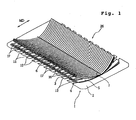
- Fig. 1 is a perspective view showing a cleaning article according to a first embodiment of the invention and taken from the side of a cleaning face;
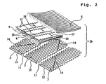
- Fig. 2 is a perspective view showing a portion of a brush portion of the cleaning article of Fig. 1 in an enlarged scale;
- Fig. 3 is a perspective view showing the cleaning article of Fig. 1 from the back side;
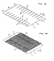
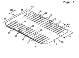
- Figs. 4A and 4B and Fig. 5 are perspective views showing the cleaning article of Fig. 1 separately of layers;
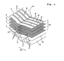
- Fig. 6 is a perspective view showing another layer structure of a cleaning article.
- a cleaning article 1 according to a first embodiment of the invention is shown with its cleaning side upward.
- the cleaning article 1 comprises a primary sheet (or base sheet) 2, and a first fiber bundle layer 3, a second fiber bundle layer 4, a secondary sheet 5 having strips formed therein, and a third fiber bundle layer 6 laminated subsequently upward on the cleaning face of the base sheet 2.
- the shorter sides of the cleaning article 1 extend parallel to the feeding direction (or MD) along which materials for the above-mentioned layers are continuously fed on the production line.
- These individual layers i.e., the base sheet 2, the first fiber bundle layer 3, the second fiber bundle layer 4, the secondary sheet 5 and the third fiber bundle layer 6) are joined altogether at an all-layer joining line 7 extending perpendicularly to MD.
- the base sheet 2 and the sheet 5 are individually formed of a nonwoven fabric formed only of or containing thermoplastic fibers (i.e., heat-fusible fibers).
- thermoplastic fibers include: fibers of PE (polyethylene), PP (polypropylene) or PET (polyethylene terephthalate) ; and conjugated fibers of PE/PET or PE/PP (e.g., conjugated fibers of a core/sheath structure having a core of PP or PET and a sheath of PE) .
- the nonwoven fabric may be a thermal bonded nonwoven fabric, a spun-bonded nonwoven fabric or a spun-laced nonwoven fabric.
- the base sheet 2 and the sheet 5 may be formed of a thermoplastic resin film such as a PE film or a PP film.
- a thermoplastic resin film such as a PE film or a PP film.
- the base sheet 2 and the sheet 5 are formed of a laminated sheet of a nonwoven fabric and a resin film.
- the base sheet 2 and the sheet 5 are formed of a through-air bonded nonwoven fabric in which the thermoplastic fibers are bonded with heated air.
- the sheet 5 is disposed to form the outermost face of the cleaning article on the cleaning side (See Fig. 6), it is desirable that the sheet 5 is formed of a through-air bonded nonwoven fabric.
- the first fiber bundle layer 3, the second fiber bundle layer 4 and the third fiber bundle layer 6 individually comprise a bundle of thermoplastic filaments. These individual filaments extend continuously to traverse each fiber bundle layer.
- a fiber bundle layer can be easily formed by opening a tow of filaments. More specifically, each fiber bundle layer can be formed over a sheet by the following steps of: opening a tow of filaments to have a predetermined width and a predetermined thickness (or bulk) , while being fed continuously in MD; joining the opened tow onto a continuously fed sheet material; and cutting the tow together with the sheet material at an interval (corresponding to the size of the cleaning article in MD) .
- the filaments may be made of any suitable materials such as PE, PP, PET, Ne (nylon) , rayon, or combination thereof.
- the filaments are conjugated fibers of a core/sheath structure having a core of PP or PET and a sheath of PE.
- the filaments are preferred to have a fineness of 1 to 50 dtex, more preferably 2 to 10 dtex.
- the individual fiber bundle layers may contain fibers of different finenesses.
- the fibers forming the fiber bundle layer of the invention should not be limited to the filaments.
- flat yarns or split yarns may also be employed.
- the flat yarns are prepared by slitting a film into tapes and by stretching the tapes in the longitudinal direction.
- the split yarns are prepared by splitting a thermoplastic film in the direction perpendicular to the orientation direction of the resin so that the film is fibrillated and interconnected into a net shape.
- the fibers forming the fiber bundle layer of the invention are crimped.
- the fiber bundle layer becomes so bulky as to take a structure enabled to capture dust easily by the crimped portions.
- crimped filaments opened from a tow are especially preferred.
- Fig. 4A shows the base sheet 2 which is formed of a spun-bonded nonwoven fabric, a through-air bonded nonwoven fabric, or the like.
- the base sheet 2 has a central region 2a, and strip-forming regions 2b and 2b lying opposite one another and sandwiching the central region 2a therebetween.
- Fig. 3 shows the base sheet 2 with its back face 2B upward. Over the back face 2B, there is laid a holding sheet 8 extending from the central region 2a to the strip-forming regions 2b and 2b.
- the holding sheet 8 is formed, like the base sheet 2, of a nonwoven fabric such as a spun-bonded nonwoven fabric, a through-air bonded nonwoven fabric, or the like.
- the holding sheet 8 may be formed of a resin film.
- the base sheet 2 and the holding sheet 8 are identical in their sizes in MD, but not identical in their sizes in the direction perpendicular to MD.
- the holding sheet 8 is shorter than the base sheet 2 in the direction perpendicular to MD.
- cut lines 11 in a zigzag shape are cut in the strip-forming regions 2b and 2b, to form a plurality of strips 12, which are separated from one another by the cut lines 11 and elongated in MD, in the base sheet 2 and the holding sheet 8.
- the first fiber bundle layer 3 Over a cleaning face 2A of the base sheet 2 having the strips 12, as shown in Fig. 4B, there is laid the first fiber bundle layer 3. At this time, the individual filaments forming the first fiber bundle layer 3 extend in MD, and the first fiber bundle layer 3 has a predetermined bulk over the cleaning face 2A of the base sheet 2.
- the base sheet 2, the holding sheet 8 disposed on the outer face 2B, and the first fiber bundle layer 3 disposed on the cleaning face 2A are joined together at joining lines 13 and 13 and joining lines 14 and 14.
- the joining is performed by heat-sealing, ultrasonic sealing or the like, so that the base sheet 2, holding sheet 8 and the first fiber bundle layer 3 are fusion-bonded at the joining lines 13 and 14.
- the paired joining lines 13, 13 are formed along the boundary lines between the central region 2a and the strip-forming regions 2b and 2b, so that they extend parallel with one another while being spaced in MD.
- the joining lines 14, 14 are formed in a zigzag shape (or in a saw-tooth shape) in the strip-forming regions 2b and 2b, respectively.
- the individual filaments forming the first fiber bundle layer 3 are joined to the underlying strips 12 at the joining lines 14 extending obliquely transversely over the strips 12 at midway areas between their longitudinal ends.
- the joining lines 14 motions of the individual filaments can be restrained so properly that the filaments are prevented from being excessively separated or entangled, while being enabled to move over the strips 12 relatively freely, to thereby exhibit an excellent dust collecting effect.
- Fig. 5 shows the state in which the second fiber bundle layer 4 and the sheet 5 are laminated.
- the sheet 5 is formed of a spun-bonded or through-air bonded nonwoven fabric, like the base sheet 2, or a resin film.
- the sheet 5 has the same size and shape as those of the base sheet 2, except for those of strips formed therein.
- the sheet 5 has a central region 5a and strip-forming regions 5b and 5b lying opposite one another and sandwiching the central 1 region 5a therebetween. These strip-forming regions 5b and 5b are cut to form a plurality of cut.lines 16 extending in a zigzag shape (or in a saw-tooth shape) from the longer side edges of the sheet 5 toward the central portion 5a in MD. Thus, there are formed a plurality of strips 17 which are separated by the cut lines 16 and elongated in MD.
- the strips 12 of the base sheet 2 shown in Fig. 4A have a length L1 and a width W1 and if the strips 17 of the sheet 5 shown in Fig. 5 have a length L2 and a width W2, L2 > L1 and W1 > W2 so that the strips 17 are thinner and longer than the strips 12.
- the individual strips 12 and 17 are formed to have widths of at least 2 mm, preferably widths of 2 to 50 mm and lengths of 10 to 100 mm.
- the second fiber bundle layer 4 is laminated on the back face 5B of the sheet 5.
- the back face 5B of the sheet 5 is directed upward, and the second fiber bundle layer 4 is laid over the back face 5B.
- the individual filaments forming the second fiber bundle layer 4 extend in MD, and the second fiber bundle layer 4 has a predetermined bulk over the back face 5B of the sheet 5.
- the strips 17 and the second fiber bundle layer 4 are joined together at joining portions 18 which are positioned midway between longitudinal ends of the strips 17.
- the strips 17 and the second fiber bundle layer 4 are fusion-bonded by heat-sealing or ultrasonic sealing.
- the joining portions 18 are formed alternately in every others of strips 17 which are arranged in the direction perpendicular to MD. In other words, the strips 17 with and without the joining portions 18 alternate with each other. However, all the strips 17 may have the joining portions 18.
- the second fiber bundle layer 4 is joined to the overlying strips 17 at the joining portions 18 positioned midway between the longitudinal ends of the strips 17. Therefore, the second fiber bundle layer 4 is retained in its shape by the strips 17 so that the filaments forming the second fiber bundle layer 4 are prevented from being excessively entangled or curled.
- the third fiber bundle layer 6 Over the cleaning face 5A of the sheet 5 of the second laminate, moreover, there is laid the third fiber bundle layer 6, as shown in Fig. 1.
- the individual filaments forming the third fiber bundle layer 6 extend in MD, and the third fiber bundle layer 6 has a substantially homogeneous bulk over the cleaning face 5A of the sheet 5.
- the holding sheet 8, the base sheet 2, the first fiber bundle layer 3, the second fiber bundle layer 4, the sheet 5 and the third fiber bundle layer 6 are joined altogether into an integral structure at the all-layer joining line 7 which extends in MD along the center line of the cleaning article 1.
- This all-layer joining line 7 is a fusing seal line by heat sealing, ultrasonic sealing or the like, so that the individual layers are fusion-bonded at the all-layer joining line 7 to be integrated altogether.
- the cleaning article 1 thus constructed has brush portions 26 at right and left sides on the cleaning face 2A of the base sheet 2. These brush portions 26 are formed by an assembly of the strips 12 of the base sheet 2, the first fiber bundle layer 3, the second fiber bundle layer 4, the strips 17 of the sheet 5 and the third fiber bundle layer 6.
- the strips 17 are interposed between the second fiber bundle layer 4 and the third fiber bundle layer 6.
- the filaments of the second fiber bundle layer 4 and the filaments of the third fiber bundle layer 6 are prevented from being excessively entangled, so that the shape of the brush portions 26 can be retained for a long term.
- the filaments of the first fiber bundle layer 3 and the filaments of the second fiber bundle layer 4 are partially joined to the strips 12 and the strips 17, respectively, so that they are prevented frombeing excessively curled or entangled. Even after a cleaning operation for a long period, therefore, the brush portions 26 are hardly crushed so that they are excellent in the shape retention.
- the base sheet 2 and the holding sheet 8, which are firstly joined at the joining lines 13 and 13, are further joined at the all-layer joining line 17 which is formed midway between the joining lines 13 and 13.
- the all-layer joining line 17 which is formed midway between the joining lines 13 and 13.
- the cleaning article 1 can be held from the outer face side by a holder 21 of a bifurcated structure, as shown in Fig. 3.
- This holder 21 includes bifurcated insert portions 22 and 22 and a grip portion 23.
- the insert portions 22 and 22 are inserted into the holding spaces 20 and 20.
- the cleaning operation can be performed by holding the grip portion 23.
- the insert portions 22 and 22 may be formed on their lower faces with a number of saw-tooth shaped protrusions 22a, which are arranged finely with sharp edges. With the protrusions 22a being directed toward the base sheet 2, the insert portions 22 and 22 are inserted into the holding spaces 20 and 20. In this inserted state, the saw-tooth shaped protrusions 22a and the base sheet 2 are retained in a high coefficient of friction so that they can prevent the cleaning article 1 from easily coming out.
- a retaining fastener 24 is also effective to fix a retaining fastener 24 on the root end portion of the insert portions 22 and 22 of the holder 21.
- This retaining fastener 24 is formed with fine hook-shaped or mushroom-shaped projections. With the retaining fastener 24 being retained on the back face 2B of the base sheet 2, the cleaning article 1 is prevented from coming out of the holder 21.
- a pivotable connect member 25 to the leading end portion of one of the bifurcated insert portions 22.
- This connect member 25 is turned, when the insert portions 22 and 22 are inserted so far into the holding spaces 20 and 20 that their leading ends pass through and come out of the holding spaces 20 and 20, to thereby retain the connect member 25 on the leading end of the other insert portion 22 by engagement between concave and convex, or the like.
- the prevention of the cleaning article 1 from coming out of the holder 21 can also be ensured by this retention.
- the holder 21 there may be provided all or at least one of the means for preventing the coming-out of the cleaning article 1 (i.e., all or at least one of the protrusions 22a, the retaining fastener 24 and the connect member 25).
- the holder 21 having such means can be used not only in the cleaning article of the invention but also in any cleaning article.
- the cleaning article 1 thus far described has a symmetrical shape, as shown in Fig. 3. Therefore, if the cleaning article 1 is used for cleaning operation while being attached to the holder 21 from the direction shown in Fig. 3 and is locally soiled, the cleaning article 1 may be removed from the holder 21 and turned 180 degrees from the position shown in Fig. 3 to be attached to the holder 21 again. If the cleaning article 1 is used for cleaning operation by changing its direction thus described above, the individual portions of the cleaning article 1 can be homogeneously used without any unbalance.
- the insert portions 22 of the holder 21 are formed of an easily deformable material, it is possible to bend arbitrarily the shape of the cleaning article 1 held by the holder 21. If the grip portion 23 is given an extensible structure, on the other hand, the cleaning operation may be performed while the grip portion 23 being extended long.
- the first fiber bundle layer 3 is joined to the base sheet 2 at the joining lines 13 and 13, as shown in Fig. 4B, so that the cleaning faces of the insertion portions 22 and 22 to be inserted into the holding spaces 20 and 20 are covered at any time not only with the base sheet 2 but also with the first fiber bundle layer 3. Therefore, even if the right or left brush portion is unintentionally turned over during cleaning operation, the first fiber bundle layer 3 exists at a predetermined sufficient thickness between the object to be cleaned and the insertion portions 22 and 22 of the holder 21. As a result, the object to be cleaned is not affected by the hardness of the holder so that the cleaning article 1 provides a smooth contact feel when used for cleaning operation.
- Fig. 6 is a perspective view showing a cleaning article 1A as a modification of the first embodiment of the invention.
- the cleaning article 1A shown in Fig. 6 is prepared by changing the order of laminations of the individual layers of the cleaning article 1 shown in Figs. 1 to 5.
- this cleaning article 1A there is provided an outermost base sheet 15 which is formed of a through-air bonded nonwoven fabric, and the base sheet 2 formed of a spun-bonded nonwoven fabric or the like is laid over the cleaning face of the this outermost base sheet 15. Over the cleaning face 2A of the base sheet 2, moreover, there are laid the first fiber bundle layer 3, the second fiber bundle layer 4, the third fiber bundle layer 6 and the sheet 5 sequentially upward.
- the sheet 5 is formed with the strips 17 and appears on the outermost face of the cleaning article 1A on its cleaning side.
- the sheet 5 may be formed of any suitable material such as a nonwoven fabric or a resin film, but is preferably formed of a through-air bonded nonwoven fabric.
- the outermost base sheet 15, the base sheet 2 and the first fiber bundle layer 3 are joined to one another on the same joining lines 13 and 13 as those shown in Fig. 4B. Moreover, all the layers from the outermost base sheet 15 to the sheet 5 having the strips 17 are joined altogether at the same all-layer joining line 7 as that shown in Figs 1 and 2. This all-layer joining line 7 extends along the center line of the cleaning article 1A.
- the third fiber bundle layer 6 and the overlying sheet 5 may be joined at the joining lines 18 positioned midway between the longitudinal ends of the strips 17 so that some of the filaments of the third fiber bundle layer 6 are partially integrated to the strips 17.
- the base sheet 2 may be formed with the plurality of strips 12, as in Fig. 4A, and the strips 12 and the first fiber bundle layer 3 may also be joined at the zigzag joining lines 14, as in Fig. 4B.
- the holding sheet 8 is joined to the outer face of the outermost base sheet 15, as in Fig. 3, to form the holding spaces 20 and 20 between the outermost base sheet 15 and the holding sheet 8.
- the sheet 5 having the strips 17 is provided to form the outermost face on the cleaning side so that it abuts preferentially against the object to be cleaned, such as floor, furniture or the like. Therefore, it is possible to prevent the filaments of the individual underlying fiber bundle layers 3, 4 and 6 from being excessively entangled or massed by the friction with the object to be cleaned. Especially if some of the filaments of the third fiber bundle layer 6 are joined at the joining lines 18 to the overlying strips 17, they are hardly entangled or massed.
- the outermost sheet 5 is formed of a highly rigid and soft through-air bonded nonwoven fabric, moreover, the brush portions 26, as formed of the strips and the fiber bundle layers, are hardly deformed by the friction with the object to be cleaned, so that they hardly lose their shapes even after used for a long term.
- the cut lines 16 for separating the strips 17 are extended to or close to the all-layer joining line 7.
- the cut lines 16 cross the whole area of the sheet 5 in MD so that the strips 17 are completely separated from each other before joined to the other layers at the all-layer joining line 7.
- the brush portions 26 can reliably retain their shapes even after use of a long term.
- the fiber bundle layer is positioned on the outermost face of the cleaning article on its cleaning side, as in the embodiment shown in Figs. 1 to 5, the filaments of the fiber bundle layer are liable to be entangled or massed by the friction with the object to be cleaned for a long term, comparatively.
- a fixing agent to the third fiber bundle layer 6 appearing on the outermost face.
- the fixing agent include an oil agent, a wax, and a resin such as a HMA (hot melt adhesive).
- HMA hot melt adhesive
- This fixing agent may be partially applied to the third fiber bundle layer 6.
- the fixing agent may be sprayed exclusively to the cleaning face of the third fiber bundle layer 6 thereby to fix the filaments appearing on the cleaning face of the third fiber bundle layer 6 exclusively.
- the fixing agent may be applied to the third fiber bundle layer 6 over a predetermined length from the all-layer joining line 7 so that the filaments forming the third fiber bundle layer 6 remain free on the side of their free ends. In both cases, the filaments forming the third fiber bundle layer 6 can be prevented from being excessively entangled, without lowering the dust trapping effect by the fiber bundle layer 6.
- the fixing agent is solid at the room temperature.
- the ratio of the wax to the fiber bundle layer 6 is preferably from 0.5 to 25 % by weight. If the ratio is less than 0.5 % by weight, the entanglement of the filaments could not be prevented effectively. If more than 25% by weight, on the other hand, the filaments will be excessively firmly fixed. Therefore, since the filaments can not be sufficiently raised, the dust trapping effect is lowered.
- the fixing agent may be prepared by mixing a wax and a HMA having a low viscosity.
- the entanglement of the filaments may be prevented not by the method of applying the fixing agent to the fiber bundle layer 6 but by solidifying the filaments of the fiber bundle layer 6 again after melting them with a solvent or by a heat. In this case, too, it is possible to firmly fix the filaments of the fiber bundle layer 6 only at the side of the all-layer joining line 7 to prevent the entanglement, while leaving the degree of freedom at the side of their leading ends so that the filament can be raised easily.
- the fixing of filaments in each fiber bundle layer should not be limited to the cleaning article 1.
- the filaments in the individual fiber bundle layers 4 and 6 may be fixed to one another with a fixing agent or by fusing them, as has been described above.
- the third fiber bundle layer 6 is joined to the other layers only at the all-layer joining line 7.
- the basis weight of the first fiber bundle layer 3 the closest to the base sheet 2 is larger than those of the overlying second fiber bundle layer 4 and third fiber bundle layer 6.
- the base sheet 2 is not exposed from the brush portions 26. Therefore, the base sheet 2 can be prevented from coming into direct contact with the object to be cleaned.
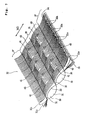
- Fig. 7 is a perspective view showing a portion of a cleaning article 30 according to a second embodiment of the invention
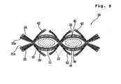
- Fig. 8 is a sectional view of the cleaning article 30.
- the cleaning article 30 comprises sheets 31 and 32 formed of a nonwoven fabric or the like, and fiber bundle layers 33 and 34.
- the sheet 31 has a plurality of strips 31a formed on its two side portions and elongated in MD.
- the sheet 32 laid over the sheet 31 also has a plurality of strips 32a formed on its two side portions. These strips 31a and 32a are formed by forming a plurality of cut lines in the two side portions of the individual sheets 31 and 32.
- the fiber bundle layer 33 is disposed on the lower face (cleaning face) of the sheet 31; and the fiber bundle layer 34 is disposed on the upper face (cleaning face) of the sheet 32.
- the sheets 31 and 32 and the fiber bundle layers 33 and 34 thus laminated are integrally fusion-bonded at a center joining line 35 and side joining lines 36 and 36.
- the two side joining lines 36 and 36 define a holding region 38 therebetween.
- two holding spaces 39 and 39 separated by the center joining line 35 are formed between the sheet 31 and the sheet 32.
- a relatively wide, single holding space may be formed between the side joining lines 36 and 36 without providing the center joining line 35.
- the holder to be inserted into the wide holding space may be given a flat shape.
- cut lines 41 each extending in the direction perpendicular to MD. Midway between adj acent joining lines 35 and 36, these cut lines 41 are arranged intermittently at a predetermined spacing. The sheets 31 and 32 and the fiber bundle layers 33 and 34 are cut altogether at those cut lines 41.
- the brush portions 37 and 37 on its two side portions are the assemblies of the fiber bundle layers 33 and 34 and the strips 31a and 32a. Therefore, the brush portions 37 have such high overall rigidities that the strips 31a and 32a can wipe off the dust whereas the fiber bundle layers 33 and 34 can trap the dust.
- the fiber brush portions 42 as formed by cutting the fiber bundle layers 33 and 34 at the cut lines 41, can exhibit the function to wipe off the dust, and the fiber bridges 43 can trap the dust wiped off. Therefore, the cleaning article 30 can exhibit the cleaning function not only at the brush portions 37 and 37 but also at both the upper and lower faces in the holding region 38, so that it can perform an effective cleaning operation at any portions.
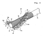
- Fig. 9 is a perspective view showing a cleaning article 50 according to a third embodiment of the invention.
- two side portions of a sheet 51 are cut at a plurality of cut lines to form a plurality of strips 51a, and two side portions of a sheet 52 are cut likewise to form a plurality of strips 52a.
- On the lower face of the sheet 51 there is disposed a fiber bundle layer 53, and on the upper face of the sheet 52, there is disposed a fiber bundle layer 54.
- the sheet 51, the sheet 52, the fiber bundle layer 53 and the fiber bundle layer 54 are integrally fusion-bonded at joining lines 55 and 56 extending in parallel.
- the joining line 55 and the joining line 56 define a holding space between the sheet 51 and the sheet 52. Into this holding space, there is inserted a holder 61. At this time, if the cleaning article 50 is attached to the holder 61 while being twisted, the brush portions 57 can be deformed to extend helically.
- the brush portions 57 are directed in all directions around the holder 61. Therefore, the cleaning article 50 can effectively trap dust when used to clean a narrow gap or the like.
- the embodiment of Fig. 7 may be given a structure in which a fiber bundle layer is further clamped between the strips 31a of the sheet 31 and the strips 32a of the sheet 32.
- the embodiment shown in Fig. 9 may also be given a structure in which a fiber bundle layer is further clamped between the strips 51a of the sheet 51 and the strips 52a of the sheet 52.
- the strips and the fiber bundle layers may be partially joined to one another midway between the longitudinal ends of the strips.
- the fibers themselves can trap the dust easily. If the fibers (e.g., filaments opened from a tow or split yarns) are joined to the sheet while being stretched in MD, and are then cut together with the sheet, moreover, the fibers are crimped so that the portions of the fiber bundle layer forming the brush portions become shorter than the strips. In this construction, it is possible to enhance both the dust trapping function by the crimped fibers and the dust wiping function by the strips extending beyond the free ends of the crimped fibers, so that the cleaning function can be effectively exhibited by the assembly of the fibers and the strips.
- the fibers e.g., filaments opened from a tow or split yarns
- the dust adsorbing and trapping effect can be enhanced by applying a dust-adsorbing agent to the fiber bundle layers and/or the strips.
- This dust-adsorbing agent is exemplified by a surface-active agent, mineral oil or wax. It is also possible to apply an acrylic adhesive or a hot melt adhesive which has a weakened adhesion.
- the fiber bundle layers and/or the strips may further contain a substance such as a deodorant, a humectant or an anti-fungus agent in addition to the dust-adsorbing agent.
- the sheets in the individual embodiments are given an elastic stretchability between the joining lines formed in the holding region, moreover, the sheets can make close contact with the holder when the cleaning article is attached to the holder, so that the cleaning article hardly comes out of the holder.
- the nonwoven fabric to be used to form the sheets having the strips should not be limited to one formed by the spun-bonding process or the through-air bonding process, but may be formed by the thermal bonding, spun-lacing, point-bonding, melt-blowing, stitch bonding, chemical bonding, needle punching or the like.
- the nonwoven fabric may be replaced by a material to be worked into the strips, such as urethane, sponge, a woven fabric, a net or a split cloth.
- the nonwoven fabric is preferred to have a basis weight of 10 to 100 g/m 2 and a thickness of 0.5 to 5 mm, from the point of view of handleability when combined with the fiber bundle layers and from the point of view of processing technique. Moreover, the nonwoven fabric is preferred to have a width of 80 to 250 mm in MD.
- the cleaning article of the invention has a brush portion formed of strips and a fiber bundle layer, so that the fibers of the fiber bundle layer can be prevented from being excessively entangled or curled, thereby to enhance the shape retention of the brush portion.
- the fiber bundle layer forming the brush portion can be enhanced in rigidity and can be prevented from being curled or shrunken even after use of a long term.
Abstract
Description
- The present invention relates to a disposable cleaning article to be held by a holder and used as a cleaning mop or by a hand and, more particularly, to a cleaning article provided with a brush portion having a high effect to trap dust and a high rigidity.
- In the cleaning article of the conventional mop type for cleaning the room, its brush portion is usually formed of twisted yarns of cotton or the like. However, the cleaning article of this kind is so expensive in manufacturing cost that it is difficult to sold it as a disposable (i.e., single-use) product. In addition, the cleaning article of this kind can absorb dust by an adhesive oil agent such as liquid paraffin, which is applied to the surfaces of the twisted yarns; but the twisted yarns per se are not good in dust trapping power. Therefore, it has a defect in capability of trapping hair or the like.
- On the other hand, the cleaning articles as disclosed in Japanese Unexamined Patent Publication Nos. 154791/1997 and 38009/1997 are designed for disposable use. These cleaning articles can be attached to a holder. The former is formed by laminating two sheets of nonwoven fabric to leave their peripheral portions unadhered to each other; and the latter is formed by cutting a peripheral portion of a nonwoven fabric to form a duster portion having long narrow strips.
- These cleaning articles, as disclosed in the above-mentioned official gazettes and formed of a nonwoven fabric, are inexpensive and suitable for disposable use. Moreover, they can easily wipe off fine dust. However, the cleaning articles per se are so flat that the capability of trapping relatively large dust is low.
- On the other hand, disposable cleaning articles in which a brush portion is formed of fibers are also known in the art. However, since the brush portion is formed only of fibers, the rigidity of the brush portion is lowered. Therefore, the fibers are entangled or curled during the cleaning operation. As a result, the portion to function substantially as the brush portion is compressed to cause a defect that the dust trapping effect of the fibers cannot be sufficiently exhibited.
- The present invention has an object to provide a cleaning article which is provided with a brush portion having a high dust collecting ability and a high shape retention and which can be manufactured at a low cost.
- According to the invention, there is provided a cleaning article having a brush portion for collecting dust, comprising: a base sheet; a fiber bundle layer of filaments disposed on a cleaning-face of said base sheet, the individual filaments extending in one direction to traverse said whole fiber bundle layer; and a cleaning-side sheet disposed on a cleaning-face of said fiber bundle layer, said cleaning-side sheet being cut from opposing edges to have a plurality of strips oriented in the same direction as the filaments, said fiber bundle layer and said cleaning-side sheet being joined to said base sheet along a longitudinal centerline of the article so that said strips and said filaments have free ends on each side of said longitudinal centerline to thereby provide brush portions, wherein a holding space, into which a hand of a user or a holder is to be inserted, is formed between said base sheet and a holding sheet disposed on a face of said base sheet opposite from the cleaning-face, said holding space being located above said fiber bundle layer and said cleaning-side sheet in a thickness direction of the article.
- This cleaning article can trap fine dust with its fiber bundle layer forming the brush portion, while suppressing the entanglement of the fibers with the strips. In addition, the strips per se can exhibit the cleaning effect. With the strips, moreover, the brush portion is so increased in rigidity as to have a high shape retention against an external force.
- Disaggregation or entanglement of fibers forming the fiber bundle layer can be suppressed so that the dust trapping ability of the brush portion is also enhanced at its face adjacent to the base material.
- The base sheet may be a sheet formed with strips. This can enhance the contact with the object to be cleaned, which may have various surface shapes, so that the dust trapping ability can be further improved.
- In the cleaning article according to the invention since the strips having a relatively high rigidity are positioned on the outermost face, there hardly occurs a phenomenon that fibers of the fiber bundle layer are entangled and fixed during the cleaning operation, so that the cleaning article can stand the use of a long term.
- It is preferred that fibers of the fiber bundle layer are fixed to one another over a predetermined length from a portion where the fiber bundle layer is joined to the base material. With the fibers of the fiber bundle layer being fixed to one another over a predetermined length from the joining portion the fibers of the fiber bundle layer can be prevented from being entangled or massed by the friction during the cleaning operation.
- It is also possible that another fiber bundle layer is provided such that one fiber bundle layer closer to the base sheet has a basis weight larger than that of the other fiber bundle layer closer to the outermost face of the cleaning article on its cleaning side. In this construction, the base sheet can be prevented during the cleaning operation from being exposed on the cleaning side of the cleaning article. In addition, the cleaning article can provide a sufficient cushioning feel during the cleaning operation.
- Preferably, the base sheet is provided on its outer face opposed to the cleaning face with a holding sheet. In this construction, for example, between the outer face of the base sheet and the holding sheet, there may be formed the holding space into which a hand of a user or a holder is enabled to be inserted.
- Moreover, the fiber bundle layer may be joined to the base sheet at two sides of the holding space extending in a direction along which the hand or holder is permitted to be inserted. In this construction, the object to be cleaned is not affected by the hardness of the holder so that the cleaning article provides a smooth contact feel when used for cleaning operation.
- The two sheets and the fiber bundle layers may further be joined to one another midway between the two joining portions to divide the holding space into two parallel holding spaces, and the fiber extending direction in the fiber bundle layers may traverse the two holding spaces. In this construction, these holding spaces are preferably opened at their two opposite ends for insertion of the holder.
- In the foregoing individual constructions, it is preferred that the fiber bundle layer is partially joined to adjacent strips, at midway positions of the adjacent strips. With this construction, the fiber bundle layer moves together with the strips so that the fiber bundle layer can be prevented from moving independently to have its fibers entangled or massed.
- Moreover, it is preferred that a sheet for forming the strips is formed of either a nonwoven fabric comprising thermoplastic fibers or a thermoplastic resin film. Also, it is preferred that the fiber bundle comprises heat-fusible thermoplastic fibers. Here, the sheet having the strips and the fiber bundle layer can be joined to each other easily and quickly by heat-fusing. Especially if the thermoplastic fibers are used for forming the sheet, the nonwoven fabric can be manufactured by a through-air bonding process to have a high rigidity and elasticity.
-
- Fig. 1 is a perspective view showing a cleaning article according to a first embodiment of the invention;
- Fig. 2 is a partially enlarged perspective view showing a brush portion of the cleaning article of Fig 1;
- Fig. 3 is a perspective view showing the cleaning article of Fig. 1 from the back side;
- Figs. 4A and 4B are perspective views showing a base sheet of the cleaning article of Fig. 1 and a laminate of the base sheet and a first fiber bundle layer, respectively;
- Fig. 5 is a perspective view showing a laminate of a second fiber bundle layer and a secondary sheet of the cleaning article of Fig. 1;
- Fig. 6 is a perspective view showing a modification of the cleaning article of the first embodiment;
- Fig. 7 is a perspective view showing a cleaning article according to a second embodiment of the invention;
- Fig. 8 is a sectional view of the cleaning article of Fig. 7; and
- Fig. 9 is a perspective view showing a modification of the cleaning article of the second embodiment.
-
- As used herein, the term "cleaning article" refers to devices having a brush portion, which are intended to be used for cleaning or sweeping purposes.
- As used herein, the term "cleaning face/cleaning side" refers to faces/sides, which are intended to be directed to the object to be cleaned or swept in use.
- As used herein, the term "strip" refers to a long narrow piece of a sheet.
- As used herein, the term "fiber bundle" refers to a bundle of a number of fibers. Examples of the fibers include filaments, flat yarns, split yarns and the like. Unless otherwise noted, these fibers are not heat-fused to one another in the fiber bundle.
- Fig. 1 is a perspective view showing a cleaning article according to a first embodiment of the invention and taken from the side of a cleaning face; Fig. 2 is a perspective view showing a portion of a brush portion of the cleaning article of Fig. 1 in an enlarged scale; Fig. 3 is a perspective view showing the cleaning article of Fig. 1 from the back side; Figs. 4A and 4B and Fig. 5 are perspective views showing the cleaning article of Fig. 1 separately of layers; and Fig. 6 is a perspective view showing another layer structure of a cleaning article.
- In Figs. 1 and 2, a
cleaning article 1 according to a first embodiment of the invention is shown with its cleaning side upward. Thecleaning article 1 comprises a primary sheet (or base sheet) 2, and a first fiber bundle layer 3, a secondfiber bundle layer 4, asecondary sheet 5 having strips formed therein, and a third fiber bundle layer 6 laminated subsequently upward on the cleaning face of thebase sheet 2. The shorter sides of thecleaning article 1 extend parallel to the feeding direction (or MD) along which materials for the above-mentioned layers are continuously fed on the production line. These individual layers (i.e., thebase sheet 2, the first fiber bundle layer 3, the secondfiber bundle layer 4, thesecondary sheet 5 and the third fiber bundle layer 6) are joined altogether at an all-layer joining line 7 extending perpendicularly to MD. - In the embodiment shown, the
base sheet 2 and thesheet 5 are individually formed of a nonwoven fabric formed only of or containing thermoplastic fibers (i.e., heat-fusible fibers). Examples of the thermoplastic fibers include: fibers of PE (polyethylene), PP (polypropylene) or PET (polyethylene terephthalate) ; and conjugated fibers of PE/PET or PE/PP (e.g., conjugated fibers of a core/sheath structure having a core of PP or PET and a sheath of PE) . The nonwoven fabric may be a thermal bonded nonwoven fabric, a spun-bonded nonwoven fabric or a spun-laced nonwoven fabric. Alternatively, thebase sheet 2 and thesheet 5 may be formed of a thermoplastic resin film such as a PE film or a PP film. Of course, it is also possible that thebase sheet 2 and thesheet 5 are formed of a laminated sheet of a nonwoven fabric and a resin film. - In order to increase the rigidity and elasticity, it is preferred that the
base sheet 2 and thesheet 5 are formed of a through-air bonded nonwoven fabric in which the thermoplastic fibers are bonded with heated air. Especially where thesheet 5 is disposed to form the outermost face of the cleaning article on the cleaning side (See Fig. 6), it is desirable that thesheet 5 is formed of a through-air bonded nonwoven fabric. - In the embodiment shown, the first fiber bundle layer 3, the second
fiber bundle layer 4 and the third fiber bundle layer 6 individually comprise a bundle of thermoplastic filaments. These individual filaments extend continuously to traverse each fiber bundle layer. Such a fiber bundle layer can be easily formed by opening a tow of filaments. More specifically, each fiber bundle layer can be formed over a sheet by the following steps of: opening a tow of filaments to have a predetermined width and a predetermined thickness (or bulk) , while being fed continuously in MD; joining the opened tow onto a continuously fed sheet material; and cutting the tow together with the sheet material at an interval (corresponding to the size of the cleaning article in MD) . The filaments may be made of any suitable materials such as PE, PP, PET, Ne (nylon) , rayon, or combination thereof. Preferably, the filaments are conjugated fibers of a core/sheath structure having a core of PP or PET and a sheath of PE. - The filaments are preferred to have a fineness of 1 to 50 dtex, more preferably 2 to 10 dtex. Here, the individual fiber bundle layers may contain fibers of different finenesses.
- However, the fibers forming the fiber bundle layer of the invention should not be limited to the filaments. For the fiber bundle layer, flat yarns or split yarns may also be employed. The flat yarns are prepared by slitting a film into tapes and by stretching the tapes in the longitudinal direction. The split yarns are prepared by splitting a thermoplastic film in the direction perpendicular to the orientation direction of the resin so that the film is fibrillated and interconnected into a net shape.
- Preferably, the fibers forming the fiber bundle layer of the invention are crimped. With the fibers being crimped, the fiber bundle layer becomes so bulky as to take a structure enabled to capture dust easily by the crimped portions. Especially preferred are crimped filaments opened from a tow.
- Here will be described the structures of the individual layers forming the
cleaning article 1 and the procedure for laminating the layers. - Fig. 4A shows the
base sheet 2 which is formed of a spun-bonded nonwoven fabric, a through-air bonded nonwoven fabric, or the like. Thebase sheet 2 has acentral region 2a, and strip-formingregions central region 2a therebetween. On the other hand, Fig. 3 shows thebase sheet 2 with itsback face 2B upward. Over theback face 2B, there is laid a holdingsheet 8 extending from thecentral region 2a to the strip-formingregions sheet 8 is formed, like thebase sheet 2, of a nonwoven fabric such as a spun-bonded nonwoven fabric, a through-air bonded nonwoven fabric, or the like. However, the holdingsheet 8 may be formed of a resin film. Thebase sheet 2 and the holdingsheet 8 are identical in their sizes in MD, but not identical in their sizes in the direction perpendicular to MD. The holdingsheet 8 is shorter than thebase sheet 2 in the direction perpendicular to MD. - With the holding
sheet 8 being laid over theouter face 2B of thebase sheet 2, cutlines 11 in a zigzag shape (or in a saw-tooth shape) are cut in the strip-formingregions strips 12, which are separated from one another by the cut lines 11 and elongated in MD, in thebase sheet 2 and the holdingsheet 8. - Over a
cleaning face 2A of thebase sheet 2 having thestrips 12, as shown in Fig. 4B, there is laid the first fiber bundle layer 3. At this time, the individual filaments forming the first fiber bundle layer 3 extend in MD, and the first fiber bundle layer 3 has a predetermined bulk over thecleaning face 2A of thebase sheet 2. - In such a laminated state, the
base sheet 2, the holdingsheet 8 disposed on theouter face 2B, and the first fiber bundle layer 3 disposed on thecleaning face 2A are joined together at joininglines lines base sheet 2, holdingsheet 8 and the first fiber bundle layer 3 are fusion-bonded at the joininglines - The paired joining
lines central region 2a and the strip-formingregions lines regions - As a result, as shown in Fig. 2 in an enlarged scale, the individual filaments forming the first fiber bundle layer 3 are joined to the
underlying strips 12 at the joininglines 14 extending obliquely transversely over thestrips 12 at midway areas between their longitudinal ends. With the joininglines 14, motions of the individual filaments can be restrained so properly that the filaments are prevented from being excessively separated or entangled, while being enabled to move over thestrips 12 relatively freely, to thereby exhibit an excellent dust collecting effect. - Fig. 5 shows the state in which the second
fiber bundle layer 4 and thesheet 5 are laminated. - The
sheet 5 is formed of a spun-bonded or through-air bonded nonwoven fabric, like thebase sheet 2, or a resin film. Thesheet 5 has the same size and shape as those of thebase sheet 2, except for those of strips formed therein. - The
sheet 5 has a central region 5a and strip-formingregions regions cut.lines 16 extending in a zigzag shape (or in a saw-tooth shape) from the longer side edges of thesheet 5 toward the central portion 5a in MD. Thus, there are formed a plurality ofstrips 17 which are separated by the cut lines 16 and elongated in MD. - If the
strips 12 of thebase sheet 2 shown in Fig. 4A have a length L1 and a width W1 and if thestrips 17 of thesheet 5 shown in Fig. 5 have a length L2 and a width W2, L2 > L1 and W1 > W2 so that thestrips 17 are thinner and longer than thestrips 12. Here, theindividual strips - The second
fiber bundle layer 4 is laminated on theback face 5B of thesheet 5. In the manufacture process, theback face 5B of thesheet 5 is directed upward, and the secondfiber bundle layer 4 is laid over theback face 5B. At this time, the individual filaments forming the secondfiber bundle layer 4 extend in MD, and the secondfiber bundle layer 4 has a predetermined bulk over theback face 5B of thesheet 5. - In such a laminated state, the
strips 17 and the secondfiber bundle layer 4 are joined together at joiningportions 18 which are positioned midway between longitudinal ends of thestrips 17. At these joiningportions 18, specifically, thestrips 17 and the secondfiber bundle layer 4 are fusion-bonded by heat-sealing or ultrasonic sealing. As shown in Fig. 5, the joiningportions 18 are formed alternately in every others ofstrips 17 which are arranged in the direction perpendicular to MD. In other words, thestrips 17 with and without the joiningportions 18 alternate with each other. However, all thestrips 17 may have the joiningportions 18. - As shown in a partially enlarged view of Fig. 2, the second
fiber bundle layer 4 is joined to the overlying strips 17 at the joiningportions 18 positioned midway between the longitudinal ends of thestrips 17. Therefore, the secondfiber bundle layer 4 is retained in its shape by thestrips 17 so that the filaments forming the secondfiber bundle layer 4 are prevented from being excessively entangled or curled. - At the final stage of the manufacture process of the
cleaning article 1, over the first laminate in which thebase sheet 2, the holdingsheet 8 and the first fiber bundle layer 3 are laminated and joined, as shown in Fig. 4B, there is laid the second laminate in which the secondfiber bundle layer 4 and thesheet 5 are laminated and joined, as shown in Fig. 5. At this lamination, the first and second laminates are laid such that the secondfiber bundle layer 4 lies over the first fiber bundle layer 3. - Over the
cleaning face 5A of thesheet 5 of the second laminate, moreover, there is laid the third fiber bundle layer 6, as shown in Fig. 1. The individual filaments forming the third fiber bundle layer 6 extend in MD, and the third fiber bundle layer 6 has a substantially homogeneous bulk over thecleaning face 5A of thesheet 5. Then, the holdingsheet 8, thebase sheet 2, the first fiber bundle layer 3, the secondfiber bundle layer 4, thesheet 5 and the third fiber bundle layer 6 are joined altogether into an integral structure at the all-layer joining line 7 which extends in MD along the center line of thecleaning article 1. This all-layer joining line 7 is a fusing seal line by heat sealing, ultrasonic sealing or the like, so that the individual layers are fusion-bonded at the all-layer joining line 7 to be integrated altogether. - As shown in Figs. 1 and 2, the
cleaning article 1 thus constructed hasbrush portions 26 at right and left sides on thecleaning face 2A of thebase sheet 2. Thesebrush portions 26 are formed by an assembly of thestrips 12 of thebase sheet 2, the first fiber bundle layer 3, the secondfiber bundle layer 4, thestrips 17 of thesheet 5 and the third fiber bundle layer 6. - When the floor, furniture, or the like is wiped with the cleaning side of the
cleaning article 1, which is shown upward in Fig. 1, fine dust can be collected by the third fiber bundle layer 6 appearing on the outermost face of thecleaning article 1, and by the first and secondfiber bundle layers 3 and 4 inside of thebrush portions 26. Here, thestrips strips - In this embodiment, the
strips 17 are interposed between the secondfiber bundle layer 4 and the third fiber bundle layer 6. When the cleaning operations are repeated, therefore, the filaments of the secondfiber bundle layer 4 and the filaments of the third fiber bundle layer 6 are prevented from being excessively entangled, so that the shape of thebrush portions 26 can be retained for a long term. - Moreover, the filaments of the first fiber bundle layer 3 and the filaments of the second
fiber bundle layer 4 are partially joined to thestrips 12 and thestrips 17, respectively, so that they are prevented frombeing excessively curled or entangled. Even after a cleaning operation for a long period, therefore, thebrush portions 26 are hardly crushed so that they are excellent in the shape retention. - On the outer face side of the
cleaning article 1 thus completed, as shown in Fig. 3, thebase sheet 2 and the holdingsheet 8, which are firstly joined at the joininglines layer joining line 17 which is formed midway between the joininglines central region 2a, therefore, there are formed twoparallel holding spaces lines 13 and the all-layer joining line 7. - Therefore, the
cleaning article 1 can be held from the outer face side by aholder 21 of a bifurcated structure, as shown in Fig. 3. Thisholder 21 includesbifurcated insert portions grip portion 23. Theinsert portions spaces grip portion 23. - It is possible to adopt a variety of structures for preventing the
cleaning article 1 from easily coming out of theholder 21 at the cleaning time. - First, the
insert portions protrusions 22a, which are arranged finely with sharp edges. With theprotrusions 22a being directed toward thebase sheet 2, theinsert portions spaces protrusions 22a and thebase sheet 2 are retained in a high coefficient of friction so that they can prevent thecleaning article 1 from easily coming out. - It is also effective to fix a retaining
fastener 24 on the root end portion of theinsert portions holder 21. This retainingfastener 24 is formed with fine hook-shaped or mushroom-shaped projections. With the retainingfastener 24 being retained on theback face 2B of thebase sheet 2, thecleaning article 1 is prevented from coming out of theholder 21. - Moreover, it is also possible to provide a
pivotable connect member 25 to the leading end portion of one of thebifurcated insert portions 22. Thisconnect member 25 is turned, when theinsert portions spaces spaces connect member 25 on the leading end of theother insert portion 22 by engagement between concave and convex, or the like. The prevention of thecleaning article 1 from coming out of theholder 21 can also be ensured by this retention. - To the
holder 21, there may be provided all or at least one of the means for preventing the coming-out of the cleaning article 1 (i.e., all or at least one of theprotrusions 22a, the retainingfastener 24 and the connect member 25). Here, theholder 21 having such means can be used not only in the cleaning article of the invention but also in any cleaning article. - The
cleaning article 1 thus far described has a symmetrical shape, as shown in Fig. 3. Therefore, if thecleaning article 1 is used for cleaning operation while being attached to theholder 21 from the direction shown in Fig. 3 and is locally soiled, thecleaning article 1 may be removed from theholder 21 and turned 180 degrees from the position shown in Fig. 3 to be attached to theholder 21 again. If thecleaning article 1 is used for cleaning operation by changing its direction thus described above, the individual portions of thecleaning article 1 can be homogeneously used without any unbalance. - Here, if the
insert portions 22 of theholder 21 are formed of an easily deformable material, it is possible to bend arbitrarily the shape of thecleaning article 1 held by theholder 21. If thegrip portion 23 is given an extensible structure, on the other hand, the cleaning operation may be performed while thegrip portion 23 being extended long. - Here in the
cleaning article 1, the first fiber bundle layer 3 is joined to thebase sheet 2 at the joininglines insertion portions spaces base sheet 2 but also with the first fiber bundle layer 3. Therefore, even if the right or left brush portion is unintentionally turned over during cleaning operation, the first fiber bundle layer 3 exists at a predetermined sufficient thickness between the object to be cleaned and theinsertion portions holder 21. As a result, the object to be cleaned is not affected by the hardness of the holder so that thecleaning article 1 provides a smooth contact feel when used for cleaning operation. - Fig. 6 is a perspective view showing a cleaning article 1A as a modification of the first embodiment of the invention.
- The cleaning article 1A shown in Fig. 6 is prepared by changing the order of laminations of the individual layers of the
cleaning article 1 shown in Figs. 1 to 5. - In this cleaning article 1A, there is provided an
outermost base sheet 15 which is formed of a through-air bonded nonwoven fabric, and thebase sheet 2 formed of a spun-bonded nonwoven fabric or the like is laid over the cleaning face of the thisoutermost base sheet 15. Over thecleaning face 2A of thebase sheet 2, moreover, there are laid the first fiber bundle layer 3, the secondfiber bundle layer 4, the third fiber bundle layer 6 and thesheet 5 sequentially upward. Thesheet 5 is formed with thestrips 17 and appears on the outermost face of the cleaning article 1A on its cleaning side. Thesheet 5 may be formed of any suitable material such as a nonwoven fabric or a resin film, but is preferably formed of a through-air bonded nonwoven fabric. - Then, the
outermost base sheet 15, thebase sheet 2 and the first fiber bundle layer 3 are joined to one another on the same joininglines outermost base sheet 15 to thesheet 5 having thestrips 17 are joined altogether at the same all-layer joining line 7 as that shown in Figs 1 and 2. This all-layer joining line 7 extends along the center line of the cleaning article 1A. - Here, as in the structure shown in Fig. 5, the third fiber bundle layer 6 and the
overlying sheet 5 may be joined at the joininglines 18 positioned midway between the longitudinal ends of thestrips 17 so that some of the filaments of the third fiber bundle layer 6 are partially integrated to thestrips 17. Moreover, thebase sheet 2 may be formed with the plurality ofstrips 12, as in Fig. 4A, and thestrips 12 and the first fiber bundle layer 3 may also be joined at thezigzag joining lines 14, as in Fig. 4B. - Of course, it is also possible that the holding
sheet 8 is joined to the outer face of theoutermost base sheet 15, as in Fig. 3, to form the holdingspaces outermost base sheet 15 and the holdingsheet 8. - In the cleaning article 1A shown in Fig. 6, the
sheet 5 having thestrips 17 is provided to form the outermost face on the cleaning side so that it abuts preferentially against the object to be cleaned, such as floor, furniture or the like. Therefore, it is possible to prevent the filaments of the individual underlying fiber bundle layers 3, 4 and 6 from being excessively entangled or massed by the friction with the object to be cleaned. Especially if some of the filaments of the third fiber bundle layer 6 are joined at the joininglines 18 to the overlying strips 17, they are hardly entangled or massed. If theoutermost sheet 5 is formed of a highly rigid and soft through-air bonded nonwoven fabric, moreover, thebrush portions 26, as formed of the strips and the fiber bundle layers, are hardly deformed by the friction with the object to be cleaned, so that they hardly lose their shapes even after used for a long term. - When the
sheet 5 having thestrips 17 forms the outermost face of the cleaning article on its cleaning side, as shown in Fig. 6, it is the more preferable that theindividual strips 17 are the longer. It is, therefore, preferred that the cut lines 16 for separating thestrips 17 are extended to or close to the all-layer joining line 7. Alternatively, it is also possible that the cut lines 16 cross the whole area of thesheet 5 in MD so that thestrips 17 are completely separated from each other before joined to the other layers at the all-layer joining line 7. - As has been described above, if the
strips 17 formed of the through-air bonded nonwoven fabric are positioned on the outermost face of the cleaning article on its cleaning side, as in the embodiment shown in Fig. 6, thebrush portions 26 can reliably retain their shapes even after use of a long term. On the other hand, if the fiber bundle layer is positioned on the outermost face of the cleaning article on its cleaning side, as in the embodiment shown in Figs. 1 to 5, the filaments of the fiber bundle layer are liable to be entangled or massed by the friction with the object to be cleaned for a long term, comparatively. - In the
cleaning article 1 shown in Figs. 1 to 5, therefore, it is preferred to apply a fixing agent to the third fiber bundle layer 6 appearing on the outermost face. Examples of the fixing agent include an oil agent, a wax, and a resin such as a HMA (hot melt adhesive). This fixing agent thus applied can prevent freedom of movement of the filaments (i.e., suppress disaggregation of the filaments) so that the filaments can be prevented from being excessively entangled or massed at the wiping time. - This fixing agent may be partially applied to the third fiber bundle layer 6. For example, the fixing agent may be sprayed exclusively to the cleaning face of the third fiber bundle layer 6 thereby to fix the filaments appearing on the cleaning face of the third fiber bundle layer 6 exclusively. Alternatively, the fixing agent may be applied to the third fiber bundle layer 6 over a predetermined length from the all-layer joining line 7 so that the filaments forming the third fiber bundle layer 6 remain free on the side of their free ends. In both cases, the filaments forming the third fiber bundle layer 6 can be prevented from being excessively entangled, without lowering the dust trapping effect by the fiber bundle layer 6. Preferably, the fixing agent is solid at the room temperature.
- In the case where a wax is used for fixing, for example, the ratio of the wax to the fiber bundle layer 6 is preferably from 0.5 to 25 % by weight. If the ratio is less than 0.5 % by weight, the entanglement of the filaments could not be prevented effectively. If more than 25% by weight, on the other hand, the filaments will be excessively firmly fixed. Therefore, since the filaments can not be sufficiently raised, the dust trapping effect is lowered.
- In the case where a HMA is used for fixing, this HMA is preferred to have a low viscosity. If a HMA having a high viscosity is used, dust trapping property is enhanced but the filaments are liable to be entangled. Of course, the fixing agent may be prepared by mixing a wax and a HMA having a low viscosity.
- Here, the entanglement of the filaments may be prevented not by the method of applying the fixing agent to the fiber bundle layer 6 but by solidifying the filaments of the fiber bundle layer 6 again after melting them with a solvent or by a heat. In this case, too, it is possible to firmly fix the filaments of the fiber bundle layer 6 only at the side of the all-layer joining line 7 to prevent the entanglement, while leaving the degree of freedom at the side of their leading ends so that the filament can be raised easily.
- Of course, the fixing of filaments in each fiber bundle layer should not be limited to the
cleaning article 1. For example, also in the cleaning article 1A shown in Fig. 6, the filaments in the individualfiber bundle layers 4 and 6 may be fixed to one another with a fixing agent or by fusing them, as has been described above. - In the
cleaning article 1 shown in Fig. 1, the third fiber bundle layer 6 is joined to the other layers only at the all-layer joining line 7. However, it is also possible to form other joining lines spaced apart from the all-layer joining line 7 to thereby join the third fiber bundle layer 6 only to theunderlying sheet 5 or to all the other layers (i.e., from thesheet 5 to the base sheet 2). This can also prevent the filaments of the third fiber bundle layer 6 from being excessively entangled or massed. - In both the
cleaning article 1 shown in Fig. 1 and the cleaning article 1A shown in Fig. 6, it is preferable that the basis weight of the first fiber bundle layer 3 the closest to thebase sheet 2 is larger than those of the overlying secondfiber bundle layer 4 and third fiber bundle layer 6. In such a construction, even if the strips or the filaments forming thebrush portions 26 are entangled or massed by repeating the cleaning operations for a long term, thebase sheet 2 is not exposed from thebrush portions 26. Therefore, thebase sheet 2 can be prevented from coming into direct contact with the object to be cleaned. - Fig. 7 is a perspective view showing a portion of a
cleaning article 30 according to a second embodiment of the invention, and Fig. 8 is a sectional view of thecleaning article 30. - The cleaning
article 30 comprisessheets sheet 31 has a plurality ofstrips 31a formed on its two side portions and elongated in MD. Thesheet 32 laid over thesheet 31 also has a plurality ofstrips 32a formed on its two side portions. Thesestrips individual sheets - The
fiber bundle layer 33 is disposed on the lower face (cleaning face) of thesheet 31; and thefiber bundle layer 34 is disposed on the upper face (cleaning face) of thesheet 32. Thesheets center joining line 35 andside joining lines side joining lines brush portions strips - The two
side joining lines region 38 therebetween. In the holdingregion 38, two holdingspaces center joining line 35 are formed between thesheet 31 and thesheet 32. Into those holdingspaces insert portions holder 21 shown in Fig. 3. Alternatively, a relatively wide, single holding space may be formed between theside joining lines center joining line 35. Here, the holder to be inserted into the wide holding space may be given a flat shape. - In the holding
region 38, moreover, there are formed cutlines 41 each extending in the direction perpendicular to MD. Midway between adj acent joininglines cut lines 41 are arranged intermittently at a predetermined spacing. Thesheets - As a result, on both the upper and lower faces (i.e., two cleaning faces) of the
cleaning article 30, filaments crossing the cut lines 41 are cut in the holdingregion 38, thereby to formfiber brush portions 42 extending from the joininglines region 38, thereby to form fiber bridges 43 extending between adjacent joininglines fiber brush portions 42 andfiber bridges 43 are alternated in the direction perpendicular to MD. - In this
cleaning article 30, thebrush portions strips brush portions 37 have such high overall rigidities that thestrips - In the holding
region 38, on the other hand, thefiber brush portions 42, as formed by cutting the fiber bundle layers 33 and 34 at the cut lines 41, can exhibit the function to wipe off the dust, and the fiber bridges 43 can trap the dust wiped off. Therefore, the cleaningarticle 30 can exhibit the cleaning function not only at thebrush portions region 38, so that it can perform an effective cleaning operation at any portions. - As shown in Fig. 8, it is also possible to provide
other layers 44 and 45 between thesheet 31 and thefiber bundle layer 33 having thefiber brush portions 42 and between thesheet 32 and thefiber bundle layer 34 having thefiber brush portions 42, respectively. Theselayers 44 and 45 are not cut at the cut lines 41 and may be formed of a fiber bundle having a large basis weight or a through-air bonded nonwoven fabric. - Fig. 9 is a perspective view showing a
cleaning article 50 according to a third embodiment of the invention. - In this
cleaning article 50, two side portions of asheet 51 are cut at a plurality of cut lines to form a plurality ofstrips 51a, and two side portions of asheet 52 are cut likewise to form a plurality ofstrips 52a. On the lower face of thesheet 51, there is disposed afiber bundle layer 53, and on the upper face of thesheet 52, there is disposed a fiber bundle layer 54. Thesheet 51, thesheet 52, thefiber bundle layer 53 and the fiber bundle layer 54 are integrally fusion-bonded at joininglines - On the two side portions beyond the joining
lines brush portions 57 of assemblies of thestrips 51a, thestrips 52a, thefiber bundle layer 53 and the fiber bundle layer 54. - The joining
line 55 and the joiningline 56 define a holding space between thesheet 51 and thesheet 52. Into this holding space, there is inserted aholder 61. At this time, if thecleaning article 50 is attached to theholder 61 while being twisted, thebrush portions 57 can be deformed to extend helically. - In this
cleaning article 50, thebrush portions 57 are directed in all directions around theholder 61. Therefore, the cleaningarticle 50 can effectively trap dust when used to clean a narrow gap or the like. - Here, the embodiment of Fig. 7 may be given a structure in which a fiber bundle layer is further clamped between the
strips 31a of thesheet 31 and thestrips 32a of thesheet 32. Likewise, the embodiment shown in Fig. 9 may also be given a structure in which a fiber bundle layer is further clamped between thestrips 51a of thesheet 51 and thestrips 52a of thesheet 52. - In the embodiments of Figs. 7 and 9, moreover, the strips and the fiber bundle layers may be partially joined to one another midway between the longitudinal ends of the strips.
- In the foregoing individual embodiments, if the fiber bundle layers are formed of crimped fibers, the fibers themselves can trap the dust easily. If the fibers (e.g., filaments opened from a tow or split yarns) are joined to the sheet while being stretched in MD, and are then cut together with the sheet, moreover, the fibers are crimped so that the portions of the fiber bundle layer forming the brush portions become shorter than the strips. In this construction, it is possible to enhance both the dust trapping function by the crimped fibers and the dust wiping function by the strips extending beyond the free ends of the crimped fibers, so that the cleaning function can be effectively exhibited by the assembly of the fibers and the strips.
- Moreover, the dust adsorbing and trapping effect can be enhanced by applying a dust-adsorbing agent to the fiber bundle layers and/or the strips. This dust-adsorbing agent is exemplified by a surface-active agent, mineral oil or wax. It is also possible to apply an acrylic adhesive or a hot melt adhesive which has a weakened adhesion.
- The fiber bundle layers and/or the strips may further contain a substance such as a deodorant, a humectant or an anti-fungus agent in addition to the dust-adsorbing agent.
- If the sheets in the individual embodiments are given an elastic stretchability between the joining lines formed in the holding region, moreover, the sheets can make close contact with the holder when the cleaning article is attached to the holder, so that the cleaning article hardly comes out of the holder.
- In the individual embodiments, the nonwoven fabric to be used to form the sheets having the strips should not be limited to one formed by the spun-bonding process or the through-air bonding process, but may be formed by the thermal bonding, spun-lacing, point-bonding, melt-blowing, stitch bonding, chemical bonding, needle punching or the like. Moreover, the nonwoven fabric may be replaced by a material to be worked into the strips, such as urethane, sponge, a woven fabric, a net or a split cloth.
- Where the sheets having the strips are formed of a nonwoven fabric, the nonwoven fabric is preferred to have a basis weight of 10 to 100 g/m2 and a thickness of 0.5 to 5 mm, from the point of view of handleability when combined with the fiber bundle layers and from the point of view of processing technique. Moreover, the nonwoven fabric is preferred to have a width of 80 to 250 mm in MD.
- As has been described above, the cleaning article of the invention has a brush portion formed of strips and a fiber bundle layer, so that the fibers of the fiber bundle layer can be prevented from being excessively entangled or curled, thereby to enhance the shape retention of the brush portion. Especially, if the strips and the fiber bundle layer are partially joined to one another, the fiber bundle layer forming the brush portion can be enhanced in rigidity and can be prevented from being curled or shrunken even after use of a long term.
- Although various exemplary embodiments have been shown and described, the invention is not limited to the embodiments shown. Therefore, the scope of the invention is intended to be limited solely by the scope of the claims that follow.
Claims (7)
- A cleaning article (1A) having a brush portion for collecting dust, comprising:a base sheet (2A);a fiber bundle layer (3, 4, 6) of filaments disposed on a cleaning-face of said base sheet, the individual filaments extending in one direction to traverse said whole fiber bundle layer; anda cleaning-side sheet (5) disposed on a cleaning-face of said fiber bundle layer, said cleaning-side sheet being cut from opposing edges to have a plurality of strips (17) oriented in the same direction as the filaments, said fiber bundle layer and said cleaning-side sheet being joined to said base sheet along a longitudinal centerline (7) of the article so that said strips and said filaments have free ends on each side of said longitudinal centerline (7) to thereby provide brush portions, whereina holding space (20), into which a hand of a user or a holder is to be inserted, is formed between said base sheet and a holding sheet (8) disposed on a face of said base sheet opposite from the cleaning-face, said holding space (20) being located above said fiber bundle layer and said cleaning-side sheet in a thickness direction of the article.
- The cleaning article as set forth in Claim 1, wherein said base sheet (2A) is also cut from opposing edges to have a plurality of strips (12) oriented in the same direction as the filaments.
- The cleaning article as set forth in Claim 1, wherein said base sheet (2A), said filaments, said cleaning-side sheet (5), and said holding sheet (8) are all thermoplastic and fusion-bonded together along said longitudinal centerline of the article.
- The cleaning article as set forth in Claim 3, wherein said fiber bundle layer is an opened tow that is laid on and cut together with said sheets.
- The cleaning article as set forth in Claim 4, wherein said base sheet (2A), said filaments, said cleaning-side sheet (5), and said holding sheet (8) are coextensive in the direction along which said filaments and said strips are oriented.
- The cleaning article as set forth in Claim 1, wherein said holding space is divided into two spaces (20, 20) each extending in a direction along which a hand of a user or a holder (21) is to be inserted.
- The cleaning article as set forth in Claim 6, wherein said holding sheet (8) is joined to said base sheet (2A) along three parallel lines (13, 7, 13): one of which is said longitudinal centreline (7); remaining two (13, 13) are disposed at equal distances on each side of said longitudinal centreline (7).
Applications Claiming Priority (5)
| Application Number | Priority Date | Filing Date | Title |
|---|---|---|---|
| JP2000208756 | 2000-07-10 | ||
| JP2000208756 | 2000-07-10 | ||
| JP2001113750 | 2001-04-12 | ||
| JP2001113750 | 2001-04-12 | ||
| EP01947846.0A EP1299026B2 (en) | 2000-07-10 | 2001-07-05 | Cleaning article |
Related Parent Applications (3)
| Application Number | Title | Priority Date | Filing Date |
|---|---|---|---|
| EP01947846.0A Division EP1299026B2 (en) | 2000-07-10 | 2001-07-05 | Cleaning article |
| EP01947846.0A Division-Into EP1299026B2 (en) | 2000-07-10 | 2001-07-05 | Cleaning article |
| EP01947846.0 Division | 2001-07-05 |
Publications (3)
| Publication Number | Publication Date |
|---|---|
| EP1523921A2 true EP1523921A2 (en) | 2005-04-20 |
| EP1523921A3 EP1523921A3 (en) | 2005-06-01 |
| EP1523921B1 EP1523921B1 (en) | 2011-02-23 |
Family
ID=26595727
Family Applications (13)
| Application Number | Title | Priority Date | Filing Date |
|---|---|---|---|
| EP06116974A Ceased EP1723886A3 (en) | 2000-07-10 | 2001-07-05 | Cleaning Article |
| EP05007606A Ceased EP1554967A3 (en) | 2000-07-10 | 2001-07-05 | Cleaning article |
| EP04030010A Expired - Lifetime EP1523923B1 (en) | 2000-07-10 | 2001-07-05 | Cleaning article |
| EP05007608A Expired - Lifetime EP1550395B1 (en) | 2000-07-10 | 2001-07-05 | Cleaning article |
| EP05007607A Expired - Lifetime EP1566135B1 (en) | 2000-07-10 | 2001-07-05 | Cleaning article |
| EP04030012A Expired - Lifetime EP1523925B1 (en) | 2000-07-10 | 2001-07-05 | Cleaning article |
| EP04030009A Expired - Lifetime EP1523922B1 (en) | 2000-07-10 | 2001-07-05 | Cleaning article |
| EP05020996A Expired - Lifetime EP1632165B1 (en) | 2000-07-10 | 2001-07-05 | Cleaning article |
| EP05007609A Expired - Lifetime EP1566136B1 (en) | 2000-07-10 | 2001-07-05 | Cleaning article |
| EP04030011A Expired - Lifetime EP1523924B1 (en) | 2000-07-10 | 2001-07-05 | Cleaning article |
| EP04030008A Expired - Lifetime EP1523921B1 (en) | 2000-07-10 | 2001-07-05 | Cleaning article |
| EP01947846.0A Expired - Lifetime EP1299026B2 (en) | 2000-07-10 | 2001-07-05 | Cleaning article |
| EP05020995A Expired - Lifetime EP1632164B1 (en) | 2000-07-10 | 2001-07-05 | Cleaning article |
Family Applications Before (10)
| Application Number | Title | Priority Date | Filing Date |
|---|---|---|---|
| EP06116974A Ceased EP1723886A3 (en) | 2000-07-10 | 2001-07-05 | Cleaning Article |
| EP05007606A Ceased EP1554967A3 (en) | 2000-07-10 | 2001-07-05 | Cleaning article |
| EP04030010A Expired - Lifetime EP1523923B1 (en) | 2000-07-10 | 2001-07-05 | Cleaning article |
| EP05007608A Expired - Lifetime EP1550395B1 (en) | 2000-07-10 | 2001-07-05 | Cleaning article |
| EP05007607A Expired - Lifetime EP1566135B1 (en) | 2000-07-10 | 2001-07-05 | Cleaning article |
| EP04030012A Expired - Lifetime EP1523925B1 (en) | 2000-07-10 | 2001-07-05 | Cleaning article |
| EP04030009A Expired - Lifetime EP1523922B1 (en) | 2000-07-10 | 2001-07-05 | Cleaning article |
| EP05020996A Expired - Lifetime EP1632165B1 (en) | 2000-07-10 | 2001-07-05 | Cleaning article |
| EP05007609A Expired - Lifetime EP1566136B1 (en) | 2000-07-10 | 2001-07-05 | Cleaning article |
| EP04030011A Expired - Lifetime EP1523924B1 (en) | 2000-07-10 | 2001-07-05 | Cleaning article |
Family Applications After (2)
| Application Number | Title | Priority Date | Filing Date |
|---|---|---|---|
| EP01947846.0A Expired - Lifetime EP1299026B2 (en) | 2000-07-10 | 2001-07-05 | Cleaning article |
| EP05020995A Expired - Lifetime EP1632164B1 (en) | 2000-07-10 | 2001-07-05 | Cleaning article |
Country Status (22)
| Country | Link |
|---|---|
| US (12) | US6813801B2 (en) |
| EP (13) | EP1723886A3 (en) |
| JP (14) | JP3630117B2 (en) |
| KR (10) | KR20050083168A (en) |
| CN (14) | CN100508865C (en) |
| AR (11) | AR030434A1 (en) |
| AT (11) | ATE448726T1 (en) |
| AU (1) | AU781602B2 (en) |
| BR (1) | BR0106947B1 (en) |
| CA (1) | CA2384357C (en) |
| CZ (1) | CZ303475B6 (en) |
| DE (10) | DE60133144T2 (en) |
| EG (1) | EG22840A (en) |
| ES (11) | ES2361014T3 (en) |
| HU (1) | HU230236B1 (en) |
| IL (1) | IL148582A (en) |
| MX (1) | MXPA02002612A (en) |
| MY (1) | MY138912A (en) |
| PL (1) | PL201659B1 (en) |
| TR (1) | TR200200601T1 (en) |
| TW (1) | TW552124B (en) |
| WO (1) | WO2002003847A2 (en) |
Cited By (5)
| Publication number | Priority date | Publication date | Assignee | Title |
|---|---|---|---|---|
| EP1974646A3 (en) * | 2007-03-30 | 2010-06-09 | Uni-Charm Corporation | Cleaning element and cleaning tool |
| US7740412B2 (en) | 2005-01-28 | 2010-06-22 | S.C. Johnson & Son, Inc. | Method of cleaning using a device with a liquid reservoir and replaceable non-woven pad |
| US7891898B2 (en) | 2005-01-28 | 2011-02-22 | S.C. Johnson & Son, Inc. | Cleaning pad for wet, damp or dry cleaning |
| US7976235B2 (en) | 2005-01-28 | 2011-07-12 | S.C. Johnson & Son, Inc. | Cleaning kit including duster and spray |
| US8893347B2 (en) | 2007-02-06 | 2014-11-25 | S.C. Johnson & Son, Inc. | Cleaning or dusting pad with attachment member holder |
Families Citing this family (193)
| Publication number | Priority date | Publication date | Assignee | Title |
|---|---|---|---|---|
| KR20050083168A (en) * | 2000-07-10 | 2005-08-25 | 유니챰 가부시키가이샤 | Cleaning article |
| JP4050035B2 (en) * | 2000-10-27 | 2008-02-20 | ユニ・チャーム株式会社 | Handy mop |
| IL152340A (en) * | 2001-02-23 | 2007-12-03 | Yoshinori Tanaka | Cleaning article |
| JP4132730B2 (en) * | 2001-06-14 | 2008-08-13 | ユニ・チャーム株式会社 | Cleaning products |
| TW200303183A (en) * | 2002-02-22 | 2003-09-01 | Yamada Chiyoe | Cleaning tool, and method for manufacturing cleaning portion constituting the cleaning tool |
| US20050066457A1 (en) * | 2003-09-26 | 2005-03-31 | Mckay William D. | Grooming/cleaning apparatus |
| US7346955B2 (en) * | 2002-12-06 | 2008-03-25 | L'oreal | Applicator structure in the form of a glove |
| JP4384448B2 (en) * | 2003-06-23 | 2009-12-16 | ユニ・チャーム株式会社 | Cleaning article and manufacturing method thereof |
| DE602004030703D1 (en) | 2003-10-31 | 2011-02-03 | Kikuo Yamada | CLEANING DEVICE |
| US6978509B2 (en) * | 2004-02-06 | 2005-12-27 | Pai Yung Lin | Cleansing device having cleansing fibers |
| US7870635B2 (en) | 2004-04-01 | 2011-01-18 | Kikuo Yamada | Cleaning tool sheet and cleaning tool |
| AU2004318325B2 (en) * | 2004-04-01 | 2009-01-08 | Kikuo Yamada | Cleaning tool sheet and cleaning tool |
| FR2870436B1 (en) * | 2004-05-21 | 2006-07-14 | Aplix Sa | FILAMENT WITH INDIVIDUAL FILAMENTS ANCHORS |
| JPWO2006011234A1 (en) * | 2004-07-30 | 2008-05-01 | 山田 千代恵 | Cleaning tool and holding member constituting cleaning tool |
| JP4021893B2 (en) * | 2004-09-09 | 2007-12-12 | ユニ・チャーム株式会社 | Cleaning tool |
| JP4688455B2 (en) * | 2004-09-09 | 2011-05-25 | ユニ・チャーム株式会社 | Cleaning tool |
| JP4573640B2 (en) * | 2004-12-10 | 2010-11-04 | ユニ・チャーム株式会社 | Cleaning tool |
| CA2584820A1 (en) * | 2004-10-20 | 2006-04-27 | The Procter & Gamble Company | Cleaning article with hand receiving opening and at least one three-dimensional side |
| US7251851B2 (en) * | 2004-11-12 | 2007-08-07 | Oimo Industrial Company, Ltd. | Spiral duster |
| JP4785369B2 (en) | 2004-11-16 | 2011-10-05 | ユニ・チャーム株式会社 | Cleaning goods |
| EP1832217B1 (en) * | 2004-12-27 | 2010-12-08 | Yamada, Chiyoe | Cleaning device and process for producing the same |
| JP4822704B2 (en) | 2004-12-28 | 2011-11-24 | ユニ・チャーム株式会社 | Cleaning tool |
| US20060168751A1 (en) * | 2005-01-28 | 2006-08-03 | Pai-Yung Lin | Double-face usable duster and the method for making the cleaning cloth thereof |
| US20060171767A1 (en) * | 2005-01-28 | 2006-08-03 | Hoadley David A | Cleaning device with liquid reservoir and replaceable non-woven pad |
| US20070180640A1 (en) * | 2005-01-28 | 2007-08-09 | S. C. Johnson & Son, Inc. | Flexible Cleaning Tool With Replaceable Non-woven Pad and Cleaning Fluid Reservoir |
| US7356869B2 (en) | 2005-04-15 | 2008-04-15 | S.C. Johnson & Son, Inc. | Flexible cleaning tool with replaceable non-woven pad |
| US7566671B2 (en) * | 2005-01-28 | 2009-07-28 | S.C. Johnson & Son, Inc. | Cleaning or dusting pad |
| US8931971B2 (en) * | 2005-01-28 | 2015-01-13 | S.C. Johnson & Son, Inc. | Cleaning pad impregnated with a volatile liquid for improved dust adhesion |
| US8851776B2 (en) * | 2005-01-28 | 2014-10-07 | S. C. Johnson & Son, Inc. | Amphiphile surface treatment for a cleaning pad for improved dust adhesion |
| US7784141B2 (en) * | 2005-01-28 | 2010-08-31 | S. C. Johnson & Son, Inc. | Flexible cleaning tool with replaceable non-woven pad and cleaning fluid reservoir |
| TWI281385B (en) * | 2005-03-10 | 2007-05-21 | Ya-Jin Yang | Duster cleaning tool |
| WO2006113386A2 (en) | 2005-04-15 | 2006-10-26 | S. C. Johnson & Son, Inc. | Flexible cleaning tool with replaceable non-woven pad and cleaning fluid reservoir |
| JP2007029136A (en) * | 2005-07-22 | 2007-02-08 | Kao Corp | Article for cleaning |
| JP4549250B2 (en) * | 2005-07-22 | 2010-09-22 | 花王株式会社 | Cleaning goods |
| TW200706146A (en) * | 2005-08-12 | 2007-02-16 | Ya-Jing Yang | Duster |
| US7962993B2 (en) | 2005-09-30 | 2011-06-21 | First Quality Retail Services, Llc | Surface cleaning pad having zoned absorbency and method of making same |
| US7694379B2 (en) | 2005-09-30 | 2010-04-13 | First Quality Retail Services, Llc | Absorbent cleaning pad and method of making same |
| US7867338B1 (en) * | 2005-10-13 | 2011-01-11 | Salvant Thomas A | Roof cleaning method |
| TWI264299B (en) * | 2005-10-17 | 2006-10-21 | Ya-Jing Yang | Dust-collecting fabric structure |
| CN101291612B (en) * | 2005-10-19 | 2010-09-15 | 花王株式会社 | Cleaning tool |
| US20070084006A1 (en) * | 2005-10-19 | 2007-04-19 | Policicchio Nicola J | Disposable dusting article |
| JP4657075B2 (en) * | 2005-10-21 | 2011-03-23 | 花王株式会社 | Cleaning goods |
| US7827650B2 (en) * | 2005-11-12 | 2010-11-09 | First Quality Retail Services, Llc | Disposable cleaning pad |
| WO2007058901A1 (en) * | 2005-11-12 | 2007-05-24 | Tyco Healthcare Retail Services, Ag | Disposable cleaning pad |
| JP4545086B2 (en) * | 2005-12-09 | 2010-09-15 | 花王株式会社 | Cleaning goods |
| JP4757017B2 (en) * | 2005-12-21 | 2011-08-24 | アズマ工業株式会社 | Wiping body for cleaning |
| JP4597880B2 (en) * | 2006-02-08 | 2010-12-15 | ユニ・チャーム株式会社 | Cleaning body and cleaning tool |
| EP1992268B1 (en) * | 2006-03-09 | 2013-01-09 | Kao Corporation | Cleaning article and production method |
| JP4859490B2 (en) * | 2006-03-09 | 2012-01-25 | 花王株式会社 | Cleaning goods |
| US20070212157A1 (en) * | 2006-03-13 | 2007-09-13 | Hoadley David A | Fringeless cleaning or dusting pad |
| US20070256264A1 (en) * | 2006-05-02 | 2007-11-08 | Yi-Chun Chen | Long-shaped bath brush |
| JP5048274B2 (en) * | 2006-05-31 | 2012-10-17 | ユニ・チャーム株式会社 | Cleaning body and cleaning tool |
| JP4909043B2 (en) * | 2006-06-27 | 2012-04-04 | 山田 千代恵 | Cleaning tool |
| US7624468B2 (en) * | 2006-07-18 | 2009-12-01 | Kimberly-Clark Worldwide, Inc. | Wet mop with multi-layer substrate |
| EP1880652A1 (en) | 2006-07-20 | 2008-01-23 | Yang, Ya Ching | Dust cloth texture |
| US7803726B2 (en) * | 2006-08-07 | 2010-09-28 | The Procter & Gamble Company | Duster system for damp and dry dusting |
| US9833118B2 (en) | 2006-08-07 | 2017-12-05 | The Procter & Gamble Company | Floor cleaning article having strips with differential bond pattern |
| US20080028560A1 (en) * | 2006-08-07 | 2008-02-07 | Nicola John Policicchio | Duster system for damp and dry dusting |
| US10617273B2 (en) | 2006-08-07 | 2020-04-14 | The Procter & Gamble Company | Floor cleaning article having strips and an absorbent core |
| JP4709105B2 (en) * | 2006-09-12 | 2011-06-22 | ユニ・チャーム株式会社 | Cleaning body and cleaning tool |
| JP4878988B2 (en) * | 2006-11-10 | 2012-02-15 | 花王株式会社 | Method for manufacturing cleaning article |
| WO2008097537A1 (en) * | 2007-02-06 | 2008-08-14 | S. C. Johnson & Son, Inc. | Cleaning or dusting pad with attachment member holder |
| ES2806378T3 (en) * | 2007-02-13 | 2021-02-17 | Yamada Kikuo | Cleaning sheet |
| EP1961359B1 (en) * | 2007-02-22 | 2012-07-11 | Carl Freudenberg KG | Wiping cover for a cleaning device |
| JP4934463B2 (en) * | 2007-03-05 | 2012-05-16 | 大日本印刷株式会社 | Cleaning tool and cleaning body |
| JP4823105B2 (en) * | 2007-03-05 | 2011-11-24 | ユニ・チャーム株式会社 | Cleaning tool and cleaning body |
| JP4934464B2 (en) * | 2007-03-05 | 2012-05-16 | 大日本印刷株式会社 | Cleaning tool |
| JP5048375B2 (en) * | 2007-03-30 | 2012-10-17 | ユニ・チャーム株式会社 | Cleaning body and cleaning tool |
| DE102007018214B4 (en) | 2007-04-16 | 2009-06-25 | Carl Freudenberg Kg | Dusting device |
| US7798342B2 (en) * | 2007-04-16 | 2010-09-21 | The Procter & Gamble Company | Product display for displaying products in an aisle at a retail store |
| JP5235478B2 (en) * | 2007-04-27 | 2013-07-10 | 花王株式会社 | Cleaning sheet |
| CN101310670B (en) * | 2007-05-24 | 2011-11-16 | 杨雅菁 | Unidirectional tightened-up structure of dust removal cloth |
| US8161594B2 (en) | 2007-07-02 | 2012-04-24 | The Procter & Gamble Company | Plural sided cleaning implement |
| US7836540B2 (en) * | 2007-08-02 | 2010-11-23 | 3M Innovative Properties Company | Broom with particle capture sheet |
| US8793832B2 (en) | 2007-12-28 | 2014-08-05 | Kikuo Yamada | Cleaning sheet |
| US8225453B2 (en) * | 2007-12-28 | 2012-07-24 | Kikuo Yamada | Cleaning sheet |
| JP4937952B2 (en) * | 2008-03-25 | 2012-05-23 | 富士フイルム株式会社 | Hazardous material removal material |
| JP5241334B2 (en) * | 2008-06-10 | 2013-07-17 | 花王株式会社 | Cleaning sheet |
| AU2009237048B2 (en) * | 2008-04-16 | 2014-09-25 | Kao Corporation | Cleaning sheet and process for producing the same |
| ES2487740T3 (en) * | 2009-02-13 | 2014-08-22 | Kao Corporation | Cleaning sheet |
| CN102101114B (en) * | 2009-02-25 | 2014-03-05 | 优罗普洛运营有限责任公司 | Steam cleaning applicators |
| US20100212098A1 (en) * | 2009-02-25 | 2010-08-26 | Euro-Pro Operating, Llc | Flexible Steam Frame For Steam Appliance |
| US20100314333A1 (en) * | 2009-06-10 | 2010-12-16 | Hollingsworth & Vose Company | Flutable fiber webs with low surface electrical resistivity for filtration |
| US8236082B2 (en) | 2009-06-19 | 2012-08-07 | Hollingsworth & Vose Company | Flutable fiber webs with high dust holding capacity |
| US20110041274A1 (en) * | 2009-08-20 | 2011-02-24 | Kumar Ogale | Cleaning article |
| JP5590840B2 (en) * | 2009-09-29 | 2014-09-17 | 大王製紙株式会社 | Cleaning sheet |
| TW201114399A (en) * | 2009-10-21 | 2011-05-01 | Ya-Jing Yang | Improved long-staple mop cloth |
| US8578564B2 (en) | 2009-11-05 | 2013-11-12 | The Procter & Gamble Company | Handle for removable cleaning implement |
| CA2685904C (en) | 2009-12-04 | 2013-05-14 | The Procter & Gamble Company | Cleaning article with non-planar element in place of strips |
| JP5641758B2 (en) * | 2010-03-31 | 2014-12-17 | 大王製紙株式会社 | Kitchen paper |
| US20110138565A1 (en) * | 2009-12-16 | 2011-06-16 | 3M Innovative Properties Company | Body cleansing device |
| US20110191973A1 (en) * | 2010-02-08 | 2011-08-11 | Shu-Han Chen | Bath brush and manufacturing method thereof |
| EP2387932A1 (en) * | 2010-05-20 | 2011-11-23 | Koninklijke Philips Electronics N.V. | Device for cleaning a surface, comprising at least one rotatable brush |
| US8336153B2 (en) | 2010-06-08 | 2012-12-25 | Galbreath Diana L | Cleaning device |
| JP5147909B2 (en) * | 2010-08-23 | 2013-02-20 | ユニ・チャーム株式会社 | Cleaning body and cleaning tool |
| JP5281065B2 (en) * | 2010-11-04 | 2013-09-04 | ユニ・チャーム株式会社 | Cleaning tool |
| JP5912503B2 (en) * | 2011-11-15 | 2016-04-27 | 山田 菊夫 | Cleaning member, cleaning tool, and folding structure of cleaning member |
| JP2013135726A (en) * | 2011-12-28 | 2013-07-11 | Kikuo Yamada | Cleaning member and cleaning tool |
| JP5746983B2 (en) | 2012-01-10 | 2015-07-08 | ユニ・チャーム株式会社 | Manufacturing apparatus and method for cleaning web member |
| USD869807S1 (en) * | 2016-10-25 | 2019-12-10 | Leonard Pellegrino | Tile and grout cleaning pad |
| USD901804S1 (en) * | 2016-10-25 | 2020-11-10 | Leonard Pellegrino | Tile and grout cleaning pad |
| USD905362S1 (en) * | 2012-01-13 | 2020-12-15 | Leonard Pellegrino | Tile and grout cleaning pad |
| USD905363S1 (en) * | 2012-01-13 | 2020-12-15 | Leonard Pellegrino | Tile and grout cleaning pad |
| US8756746B2 (en) | 2012-03-09 | 2014-06-24 | The Procter & Gamble | Cleaning article with elastically contracted sheet |
| US8893345B2 (en) | 2012-03-09 | 2014-11-25 | The Procter & Gamble Company | Cleaning article with apertured sheet and tow fibers |
| US8931132B2 (en) | 2012-03-09 | 2015-01-13 | The Procter & Gamble Company | Cleaning article with differential overlap between sheet and tow fibers |
| US9198553B2 (en) | 2012-03-09 | 2015-12-01 | The Procter & Gamble Company | Cleaning article with upstanding elastic panel |
| KR101882952B1 (en) * | 2012-04-05 | 2018-07-27 | 주식회사 엘지생활건강 | Cleaning sheet containing composition for cleansing and having improved detergency |
| TWM437151U (en) * | 2012-04-13 | 2012-09-11 | Ya-Jing Yang | Dust wiper dusting cloth structure |
| JP5871711B2 (en) | 2012-05-21 | 2016-03-01 | ユニ・チャーム株式会社 | Web member cutting apparatus having a plurality of fibers including tows, and cutting method |
| JP5656915B2 (en) | 2012-05-21 | 2015-01-21 | ユニ・チャーム株式会社 | Web member cutting apparatus having a plurality of fibers including tows, and cutting method |
| JP5836194B2 (en) | 2012-05-21 | 2015-12-24 | ユニ・チャーム株式会社 | Cutting apparatus for continuous web having a plurality of fibers including tow, and cutting method |
| US10111564B2 (en) | 2012-08-06 | 2018-10-30 | Thomas K. Schultheis | Upward and radial floor cleaning apparatus |
| US10117555B2 (en) | 2013-03-21 | 2018-11-06 | Thomas K. Schultheis | Upward cleaning vacuum cleaning apparatus |
| ITMI20121738A1 (en) * | 2012-10-16 | 2014-04-17 | Orlandi Spa | INSTRUMENT FOR CLEANING SURFACES |
| US20140138512A1 (en) | 2012-11-16 | 2014-05-22 | The Procter & Gamble Company | Cleaning system and display |
| JP6047400B2 (en) | 2012-12-29 | 2016-12-21 | ユニ・チャーム株式会社 | Method and apparatus for manufacturing a cleaning member |
| US10098516B2 (en) | 2012-12-29 | 2018-10-16 | Unicharm Corporation | Method for producing cleaning member, and system for producing cleaning member |
| US20140187406A1 (en) | 2012-12-29 | 2014-07-03 | Unicharm Corporation | Method of producing cleaning member |
| JP6047401B2 (en) | 2012-12-29 | 2016-12-21 | ユニ・チャーム株式会社 | Manufacturing method of opened fiber bundle, manufacturing method of cleaning member, fiber bundle opening device, and cleaning member manufacturing system |
| JP6037828B2 (en) | 2012-12-29 | 2016-12-07 | ユニ・チャーム株式会社 | Manufacturing method of opened fiber bundle, manufacturing method of cleaning member, fiber bundle opening device, and cleaning member manufacturing system |
| JP6073128B2 (en) | 2012-12-29 | 2017-02-01 | ユニ・チャーム株式会社 | Cutting device and method for manufacturing cleaning member using cutting device |
| JP6080550B2 (en) | 2012-12-29 | 2017-02-15 | ユニ・チャーム株式会社 | Fusing device for sealing a belt-like sheet |
| JP6057707B2 (en) | 2012-12-29 | 2017-01-11 | ユニ・チャーム株式会社 | Manufacturing method of opened fiber bundle, manufacturing method of cleaning member, fiber bundle opening device, and cleaning member manufacturing system |
| US20140182767A1 (en) | 2012-12-29 | 2014-07-03 | Unicharm Corporation | Method of producing cleaning member |
| JP6141023B2 (en) | 2013-01-10 | 2017-06-07 | ユニ・チャーム株式会社 | Manufacturing method of web member including tow |
| JP6103945B2 (en) | 2013-01-10 | 2017-03-29 | ユニ・チャーム株式会社 | Stacking apparatus and method for manufacturing web member |
| JP6208948B2 (en) * | 2013-02-07 | 2017-10-04 | ユニ・チャーム株式会社 | Cleaning tool |
| JP6228366B2 (en) * | 2013-02-07 | 2017-11-08 | ユニ・チャーム株式会社 | Cleaning tool |
| JP6126398B2 (en) | 2013-02-07 | 2017-05-10 | ユニ・チャーム株式会社 | Cleaning tool |
| JP6323980B2 (en) * | 2013-02-07 | 2018-05-16 | ユニ・チャーム株式会社 | Cleaning tool |
| JP6323981B2 (en) * | 2013-02-07 | 2018-05-16 | ユニ・チャーム株式会社 | Cleaning tool |
| JP6208949B2 (en) * | 2013-02-07 | 2017-10-04 | ユニ・チャーム株式会社 | Cleaning tool |
| US9849638B2 (en) | 2013-02-08 | 2017-12-26 | The Procter & Gamble Company | Process and apparatus for fluffing a cleaning implement |
| JP6158953B2 (en) | 2013-02-08 | 2017-07-05 | ザ プロクター アンド ギャンブル カンパニー | Kit for fluffing cleaning supplies |
| JP6486688B2 (en) | 2013-02-08 | 2019-03-20 | ユニ・チャーム株式会社 | Cleaning tool manufacturing method and manufacturing apparatus |
| KR200476647Y1 (en) * | 2013-06-03 | 2015-03-18 | 주식회사 엘지생활건강 | Sheet for cleaning having cutting line |
| US9204777B2 (en) * | 2013-06-20 | 2015-12-08 | Ez Products Of South Florida, L.L.C. | Duster with interior sleeve |
| JP6228407B2 (en) * | 2013-09-03 | 2017-11-08 | ユニ・チャーム株式会社 | Cleaning tool and method of manufacturing cleaning tool |
| GB2566851B (en) * | 2014-03-20 | 2019-08-07 | Schultheis Tom | Floor steam cleaning apparatus with cleaning element |
| JP6474559B2 (en) * | 2014-08-06 | 2019-02-27 | 花王株式会社 | Cleaning tool |
| JP6514863B2 (en) * | 2014-08-08 | 2019-05-15 | ユニ・チャーム株式会社 | Cleaning sheet and cleaning tools |
| EP2995321B1 (en) | 2014-09-15 | 2017-07-26 | Procter & Gamble International Operations SA | A consumer goods product comprising chitin nanofibrils, lignin and a polymer or co-polymer |
| US20160106294A1 (en) | 2014-10-16 | 2016-04-21 | The Procter & Gamble Company | Kit having a package containing cleaning implements, package therefor and blank therefor |
| EP3017880B1 (en) * | 2014-11-07 | 2019-03-20 | Black & Decker Inc. | Steam cleaning device and accessory |
| CA2966472A1 (en) | 2014-11-28 | 2016-06-02 | Unicharm Corporation | Method and apparatus for forming compression-bonding portion to continuous body of web member with fiber bundle |
| WO2016084251A1 (en) | 2014-11-28 | 2016-06-02 | ユニ・チャーム株式会社 | Method for forming crimped parts in continuous body of web member having fiber bundles, and formation device |
| WO2016143147A1 (en) * | 2015-03-12 | 2016-09-15 | ユニ・チャーム株式会社 | Cleaning sheet and cleaning instrument |
| CA2981656C (en) | 2015-04-02 | 2019-12-03 | The Procter & Gamble Company | Floor cleaning article having strips with differential bond pattern |
| WO2016161234A1 (en) | 2015-04-02 | 2016-10-06 | The Procter & Gamble Company | Floor cleaning article having strips and an absorbent core |
| EP3078316B1 (en) | 2015-04-09 | 2019-11-20 | The Procter and Gamble Company | Cleaning article having discrete seal bonds |
| US11229343B2 (en) | 2015-06-30 | 2022-01-25 | The Procter & Gamble Company | Cleaning article having multi-layer gather strip element |
| US10874279B2 (en) | 2015-12-15 | 2020-12-29 | The Procter & Gamble Company | Compressible pre-moistened fibrous structures |
| US20170164809A1 (en) | 2015-12-15 | 2017-06-15 | The Procter & Gamble Company | Pre-Moistened Fibrous Structures |
| EP3390718B1 (en) | 2015-12-15 | 2021-03-03 | The Procter and Gamble Company | Fibrous structures comprising regions having different solid additive levels |
| US20170164808A1 (en) | 2015-12-15 | 2017-06-15 | The Procter & Gamble Company | Pre-Moistened Fibrous Structures Exhibiting Increased Mileage |
| EP3390722B1 (en) | 2015-12-15 | 2020-07-15 | The Procter and Gamble Company | Fibrous structures comprising three or more regions |
| ES2866077T3 (en) | 2015-12-15 | 2021-10-19 | Procter & Gamble | Pre-moistened fibrous structures that exhibit higher capacity |
| US10428463B2 (en) | 2015-12-15 | 2019-10-01 | The Procter & Gamble Company | Fibrous structures comprising regions having different micro-CT intensive property values and associated transition slopes |
| US9963230B2 (en) | 2016-01-11 | 2018-05-08 | The Procter & Gamble Company | Aerial drone cleaning device and method of cleaning a target surface therewith |
| KR101942072B1 (en) * | 2016-01-29 | 2019-01-25 | 남양부직포 주식회사 | Non-woven Fabric Manufacturing Apparatus having Cleaning Function |
| EP3429523B1 (en) | 2016-03-15 | 2019-12-25 | The Procter and Gamble Company | Method and apparatus for manufacturing an absorbent article including an ultra short pulse laser source |
| WO2017160900A1 (en) | 2016-03-15 | 2017-09-21 | The Procter & Gamble Company | Method and apparatus for manufacturing an absorbent article including an ultra short pulse laser source |
| US20170266941A1 (en) | 2016-03-15 | 2017-09-21 | The Procter & Gamble Company | Method and Apparatus for Manufacturing an Absorbent Article Including an Ultra Short Pulse Laser Source |
| US11172803B2 (en) | 2016-08-12 | 2021-11-16 | The Procter & Gamble Company | Cleaning sheets having coating thereon |
| CA3043527C (en) | 2016-12-08 | 2021-08-24 | The Procter & Gamble Company | Pre-moistened cleaning pads |
| CA3043530C (en) | 2016-12-08 | 2021-06-01 | The Procter & Gamble Company | Cleaning pad with split core fibrous structures |
| EP3551150A1 (en) | 2016-12-08 | 2019-10-16 | The Procter and Gamble Company | Fibrous structures having a contact surface |
| US11458515B2 (en) * | 2017-01-26 | 2022-10-04 | Unger Marketing International, Llc | Cleaning devices for cleaning of difficult to reach locations |
| US11006738B2 (en) | 2017-01-26 | 2021-05-18 | Unger Marketing International, Llc | Cleaning devices having selectively flexible or rigid handles |
| US10694915B2 (en) | 2017-04-06 | 2020-06-30 | The Procter & Gamble Company | Sheet with tow fiber and movable strips |
| JP2020531125A (en) | 2017-09-11 | 2020-11-05 | ザ プロクター アンド ギャンブル カンパニーThe Procter & Gamble Company | Cleaning supplies with irregularly spaced tow tufts |
| US11045061B2 (en) | 2017-09-11 | 2021-06-29 | The Procter & Gamble Company | Method of making a tufted laminated cleaning article |
| US11253128B2 (en) | 2017-09-11 | 2022-02-22 | The Procter & Gamble Company | Cleaning article with differential pitch tow tufts |
| US10730081B2 (en) | 2017-09-11 | 2020-08-04 | The Procter & Gamble Company | Method of making a cleaning article having cutouts |
| EP3453305B1 (en) | 2017-09-11 | 2022-11-02 | The Procter & Gamble Company | Method of making a tufted laminated cleaning article |
| JP2019051130A (en) * | 2017-09-15 | 2019-04-04 | ユニ・チャーム株式会社 | Cleaning tool |
| US10722091B2 (en) | 2017-10-06 | 2020-07-28 | The Procter & Gamble Company | Cleaning article with preferentially coated tow fibers |
| US10653286B2 (en) | 2017-10-06 | 2020-05-19 | The Procter & Gamble Company | Cleaning article with preferential coating |
| EP3720689B1 (en) | 2017-12-07 | 2023-07-19 | The Procter & Gamble Company | Flexible bonding |
| US11903542B2 (en) | 2018-04-03 | 2024-02-20 | The Procter & Gamble Company | Cleaning article with double bonded tow tufts |
| US11375867B2 (en) * | 2018-04-03 | 2022-07-05 | The Procter & Gamble Company | Cleaning article with differential sized tow tufts |
| US20190298141A1 (en) * | 2018-04-03 | 2019-10-03 | The Procter & Gamble Company | Cleaning article with irregularly spaced tow tufts |
| US11389986B2 (en) | 2018-12-06 | 2022-07-19 | The Procter & Gamble Company | Compliant anvil |
| US11000114B2 (en) * | 2019-03-06 | 2021-05-11 | Nasr Said AGHA | Lockable holder and replaceable cleaning head |
| JP7002490B2 (en) * | 2019-03-08 | 2022-01-20 | ユニ・チャーム株式会社 | Cleaning sheet |
| WO2020183922A1 (en) * | 2019-03-08 | 2020-09-17 | ユニ・チャーム株式会社 | Cleaning sheet |
| WO2021054817A1 (en) * | 2019-09-17 | 2021-03-25 | Fook Yuen Lee | Brush cleaning elements and method of manufacturing thereof |
| DE102019130744A1 (en) * | 2019-11-14 | 2021-05-20 | Carl Freudenberg Kg | Wiper unit and wiper device |
| US20210315434A1 (en) | 2020-04-10 | 2021-10-14 | The Procter & Gamble Company | Cleaning article with preferential rheological solid composition |
| US11812909B2 (en) | 2020-04-10 | 2023-11-14 | The Procter & Gamble Company | Cleaning implement with a rheological solid composition |
| EP4229161A1 (en) | 2020-10-16 | 2023-08-23 | The Procter & Gamble Company | Cleaning article with preferential coating |
| US11833237B2 (en) | 2021-03-09 | 2023-12-05 | The Procter & Gamble Company | Method for enhancing scalp active deposition |
Citations (3)
| Publication number | Priority date | Publication date | Assignee | Title |
|---|---|---|---|---|
| US823725A (en) * | 1905-09-09 | 1906-06-19 | Henry A Hayden | Duster. |
| EP0848927A1 (en) * | 1996-12-17 | 1998-06-24 | Helen Daniels | Cleaning implement |
| EP0943425A1 (en) * | 1998-03-19 | 1999-09-22 | Uni-Charm Corporation | Disposable cleaning sheet |
Family Cites Families (111)
| Publication number | Priority date | Publication date | Assignee | Title |
|---|---|---|---|---|
| US1437145A (en) * | 1921-07-21 | 1922-11-28 | Theodore G Johnson | Duster |
| US1542108A (en) | 1923-05-23 | 1925-06-16 | George E Taylor | Bottle cleaner |
| GB979918A (en) | 1962-07-30 | 1965-01-06 | Du Pont | Improvements relating to textile products |
| GB1178753A (en) | 1967-05-10 | 1970-01-21 | Ici Ltd | Improvements in or relating to Intermingling Jets for Multifilament Yarn |
| US3495918A (en) * | 1967-12-15 | 1970-02-17 | Ragnvald G Leland | Disposable swab and holder |
| US3525113A (en) * | 1968-08-16 | 1970-08-25 | Ragnvald G Leland | Mop with removable holder |
| US3822435A (en) | 1972-12-22 | 1974-07-09 | T Moss | Disposable dust mop and method of making same |
| US3985225A (en) | 1975-03-05 | 1976-10-12 | Sergei Alexeevich Baum | Chain conveyor with support chain |
| US3986225A (en) | 1975-09-02 | 1976-10-19 | Duskin Franchise Co. Ltd. | Mop holder |
| US4010511A (en) * | 1976-02-06 | 1977-03-08 | Duskin Franchise Co., Ltd. | Mop having sleeve type detachable mop head |
| FR2403773A2 (en) * | 1977-09-21 | 1979-04-20 | Lelievre Andree Francoise | Mop head made of strips of material - cut from rectangular piece and fringed at ends, placed on top of each other and clipped together |
| JPS5513570A (en) | 1978-07-14 | 1980-01-30 | Nec Corp | Automatic raising system of double central control units at trouble time |
| US4423532A (en) * | 1981-04-23 | 1984-01-03 | Duskin Franchise Kabushiki Kaisha | Duster |
| US4364144A (en) * | 1981-05-18 | 1982-12-21 | Seco Industries, Inc. | Duster head and method of making same |
| IL64766A (en) * | 1982-01-12 | 1984-10-31 | Jochanan Ksieski | Rubber or plastic broom |
| JPS58177071A (en) * | 1982-04-09 | 1983-10-17 | Fuji Xerox Co Ltd | Shading compensation device |
| JPS5935853B2 (en) † | 1982-05-04 | 1984-08-31 | 電気化学工業株式会社 | cement additives |
| JPS58177071U (en) * | 1982-05-22 | 1983-11-26 | 日本リ−スキン株式会社 | Mounting structure of motsupu and its handle |
| JPS6247351A (en) † | 1985-08-27 | 1987-03-02 | 持田製薬株式会社 | Laser knife apparatus having manipulator |
| EP0289198B1 (en) | 1987-04-24 | 1992-02-12 | The Procter & Gamble Company | Loop fastening material for fastening device and method of making same |
| JPS6479455A (en) | 1987-09-17 | 1989-03-24 | Kubota Ltd | Automatic relief valve for speed change operation of power transmission |
| JPS6479454A (en) | 1987-09-17 | 1989-03-24 | Mazda Motor | Hydraulic control device for automatic transmission |
| JP2646576B2 (en) | 1987-09-18 | 1997-08-27 | 日産自動車株式会社 | Travel control device for vehicles with automatic transmission |
| DE3734850A1 (en) * | 1987-10-14 | 1989-04-27 | Zweegers & Zonen P J | METHOD FOR PRODUCING HARVEST BALLS AND DEVICE FOR CARRYING OUT THE METHOD |
| JPH01178859A (en) | 1988-01-08 | 1989-07-17 | Hitachi Ltd | Inspecting apparatus of defect of pipe joint |
| DE3802198A1 (en) * | 1988-01-26 | 1989-06-29 | Karin Fuchs | Mop with optimised cleaning device |
| JPH0743515B2 (en) † | 1988-06-15 | 1995-05-15 | 富士写真フイルム株式会社 | Silver halide photographic light-sensitive material |
| JP2734528B2 (en) | 1988-06-23 | 1998-03-30 | 富士ゼロックス株式会社 | Electrostatic recording head |
| ES2011112A6 (en) | 1988-09-15 | 1989-12-16 | Vileda Gmbh | Polishing mop for floors and other surfaces. |
| JPH0334285A (en) | 1989-06-29 | 1991-02-14 | Murata Mfg Co Ltd | Organic positive property thermistor |
| JPH0785583B2 (en) | 1989-06-30 | 1995-09-13 | パイオニア株式会社 | Satellite broadcasting reception system |
| JP2754757B2 (en) | 1989-07-03 | 1998-05-20 | 富士ゼロックス株式会社 | Composite simultaneous molding die and method of molding composite material using the die |
| JPH0340633A (en) | 1989-07-07 | 1991-02-21 | Toshiba Corp | Terminal adaptor |
| JPH0624470B2 (en) | 1989-07-12 | 1994-04-06 | 宝幸水産株式会社 | How to make squid meal |
| US5124157A (en) | 1989-08-18 | 1992-06-23 | Cygnus Therapeutic Systems | Method and device for administering dexmedetomidine transdermally |
| JP3036008B2 (en) | 1990-07-18 | 2000-04-24 | 日本電気株式会社 | Semiconductor storage device |
| JP3034285B2 (en) | 1990-07-31 | 2000-04-17 | 株式会社東芝 | Charged beam exposure equipment |
| KR920003902A (en) * | 1990-08-04 | 1992-03-27 | 김지현 | Differential crusher |
| DE4025646A1 (en) | 1990-08-14 | 1992-02-20 | Henkel Kgaa | WIPE COVER WITH HOLDER IMPORTANT |
| NL9002008A (en) * | 1990-09-12 | 1992-04-01 | Stichting Centr Diergeneeskund | RECOMBINANT DNA AND RNA AND PRODUCTS DERIVED THEREFROM. |
| CN2083909U (en) * | 1990-11-29 | 1991-09-04 | 陈文榕 | Mop |
| US5140718A (en) * | 1990-12-07 | 1992-08-25 | Toth John B | Spar track cleaning and maintenance device |
| JPH05192284A (en) | 1990-12-14 | 1993-08-03 | Daiwabo Create Kk | Cloth for cleaning |
| JP3044823B2 (en) | 1991-05-28 | 2000-05-22 | 松下電器産業株式会社 | Magnetic recording device |
| US5221124A (en) * | 1991-07-11 | 1993-06-22 | Milliken Research Corporation | Method to manufacture a wet mop head |
| JP3032354B2 (en) † | 1991-09-30 | 2000-04-17 | キヤノン株式会社 | Facsimile machine |
| JP3034692B2 (en) | 1992-05-28 | 2000-04-17 | 三菱電機株式会社 | Vacuum reactor and semiconductor substrate processing method |
| JP3040633B2 (en) | 1993-03-31 | 2000-05-15 | 光洋精工株式会社 | Magnetic bearing device |
| EP0647115B1 (en) | 1993-04-29 | 1997-08-13 | METAFORM METALLVERARBEITUNGSGESELLSCHAFT mbH | Cleaning cloth |
| JPH078432A (en) | 1993-06-28 | 1995-01-13 | Asahi Chem Ind Co Ltd | Cleaning material |
| JPH0723886A (en) | 1993-07-07 | 1995-01-27 | Asahi Chem Ind Co Ltd | Wiping cloth material |
| JPH0767821A (en) † | 1993-08-31 | 1995-03-14 | Tokai:Kk | Hand mop with handle |
| US5452491A (en) * | 1994-04-04 | 1995-09-26 | Milliken Research Corporation | Dust mop |
| JP3683610B2 (en) | 1995-02-14 | 2005-08-17 | アズマ工業株式会社 | Telescopic mop |
| ES1030456Y (en) * | 1995-03-22 | 1996-02-16 | Mery Sa | MOPA FRIEGASUELOS. |
| JPH08266455A (en) | 1995-03-30 | 1996-10-15 | Toray Ind Inc | Mop made of polyamide |
| JPH08336493A (en) † | 1995-06-09 | 1996-12-24 | Teramoto:Kk | Mop holder |
| JP3320949B2 (en) | 1995-06-12 | 2002-09-03 | 日本電話施設株式会社 | Pipe cutting tools |
| JPH0919396A (en) | 1995-07-04 | 1997-01-21 | Azuma Kogyo Kk | Cleaning tool for using disposable wiping member |
| JP3571420B2 (en) | 1995-07-07 | 2004-09-29 | アズマ工業株式会社 | Cleaning tool using disposable wiping material |
| JP2793980B2 (en) * | 1995-07-12 | 1998-09-03 | 株式会社シマノ | Snowboard boots |
| JP2977477B2 (en) | 1995-12-08 | 1999-11-15 | 花王株式会社 | Cleaning tools |
| WO1997004701A1 (en) * | 1995-08-01 | 1997-02-13 | Kao Corporation | Cleaning cloth and cleaning apparatus |
| JPH0938009A (en) | 1995-08-01 | 1997-02-10 | Kao Corp | Cloth, handle and tool for cleaning |
| JPH0947416A (en) † | 1995-08-09 | 1997-02-18 | Azuma Kogyo Kk | Mop |
| JP3655365B2 (en) | 1995-08-09 | 2005-06-02 | アズマ工業株式会社 | mop |
| EP0759283A1 (en) * | 1995-08-18 | 1997-02-26 | Minnesota Mining And Manufacturing Company | Mops |
| DE19542563A1 (en) | 1995-11-15 | 1997-05-22 | Flender A F & Co | Device for sealing a protective hood of a mill body |
| JP3208306B2 (en) † | 1995-11-17 | 2001-09-10 | ユニ・チャーム株式会社 | Disposable wiping tools |
| JP3124478B2 (en) * | 1995-12-01 | 2001-01-15 | ユニ・チャーム株式会社 | Manufacturing method of disposable wiping tools |
| JP3815517B2 (en) | 1996-02-09 | 2006-08-30 | チッソ株式会社 | Tow |
| JP3624996B2 (en) | 1996-03-15 | 2005-03-02 | 花王株式会社 | Cleaning tool |
| JP3224746B2 (en) | 1996-03-15 | 2001-11-05 | 花王株式会社 | Cleaning tools |
| JP3450605B2 (en) | 1996-03-15 | 2003-09-29 | 花王株式会社 | Cleaning tools |
| DE29701349U1 (en) * | 1997-01-28 | 1997-04-30 | Grabarits Dieter | Device for wet cleaning of floors or similar surfaces |
| US6119298A (en) | 1999-01-12 | 2000-09-19 | Uni-Charm Corporation | Disposable wiping sheet |
| JP3706433B2 (en) | 1996-06-28 | 2005-10-12 | ユニ・チャーム株式会社 | Sheet cleaning material |
| US6502273B1 (en) | 1996-11-08 | 2003-01-07 | Kanebo, Ltd. | Cleaning sponge roller |
| JP3403108B2 (en) | 1999-02-26 | 2003-05-06 | アイオン株式会社 | Sponge roller for cleaning |
| WO1998020987A1 (en) | 1996-11-08 | 1998-05-22 | Kanebo Limited | Sponge roller for cleaning |
| US5889413A (en) * | 1996-11-22 | 1999-03-30 | Xilinx, Inc. | Lookup tables which double as shift registers |
| JP3359514B2 (en) | 1996-12-02 | 2002-12-24 | ユニ・チャーム株式会社 | Disposable cleaning supplies |
| JP2930916B2 (en) | 1997-02-13 | 1999-08-09 | アオイ紡績株式会社 | Wiping cleaning tool |
| US5715560A (en) | 1997-02-18 | 1998-02-10 | Banicki; Kathy | Scrub brush with integral handle and cleaning elements |
| JP3666772B2 (en) | 1997-02-26 | 2005-06-29 | 花王株式会社 | Telescopic rod |
| JP3409988B2 (en) † | 1997-03-21 | 2003-05-26 | ユニ・チャーム株式会社 | Wipe sheet |
| US6084447A (en) * | 1997-03-28 | 2000-07-04 | Cypress Semiconductor Corp. | Pulse discriminating clock synchronizer for logic derived clock signals with synchronous clock suspension capability for a programmable device |
| JP3027345B2 (en) * | 1997-05-15 | 2000-04-04 | 花王株式会社 | Cleaning tools |
| US6241838B1 (en) * | 1997-09-08 | 2001-06-05 | Murata Manufacturing Co., Ltd. | Method of producing a multi-layer ceramic substrate |
| JPH1189776A (en) | 1997-09-19 | 1999-04-06 | Kao Corp | Cleaning cloth and tool |
| TW394679B (en) * | 1997-12-16 | 2000-06-21 | Uni Charm Corp | Cleaning article and its manufacturing method |
| US6143393A (en) | 1997-12-16 | 2000-11-07 | Uni-Charm Corporation | Cleaning product and production process therefor |
| JP3100578B2 (en) * | 1997-12-16 | 2000-10-16 | ユニ・チャーム株式会社 | Cleaning article and method for manufacturing the same |
| JP3628171B2 (en) † | 1998-03-27 | 2005-03-09 | ユニ・チャーム株式会社 | Cleaning mop |
| ATE349178T1 (en) † | 1998-04-30 | 2007-01-15 | Sanamundi Ag | CLEANING TEXTILE |
| JP3558892B2 (en) † | 1998-09-24 | 2004-08-25 | ユニ・チャーム株式会社 | Cleaning sheet |
| ID27093A (en) | 1999-03-05 | 2001-03-01 | Uni Charm Corp | COMPOSITE SHEET AND METHOD OF MAKING |
| JP2000296084A (en) | 1999-04-13 | 2000-10-24 | Uni Charm Corp | Disposable wiping tool and its manufacture |
| JP3943753B2 (en) | 1999-04-13 | 2007-07-11 | ユニ・チャーム株式会社 | Method for producing disposable dirt wiping tool |
| JP2000296085A (en) | 1999-04-13 | 2000-10-24 | Uni Charm Corp | Disposable wiping tool and its manufacture |
| TW402079U (en) | 1999-12-31 | 2000-08-11 | Oimo Ind Co Ltd | Improved screen at the ventilation inlet of air conditioner |
| US6713413B2 (en) † | 2000-01-03 | 2004-03-30 | Freudenberg Nonwovens Limited Partnership | Nonwoven buffing or polishing material having increased strength and dimensional stability |
| TW413052U (en) | 2000-01-24 | 2000-11-21 | Tsai Tzung Chi | Dual-purposes device with massage and brushing function |
| JP3898408B2 (en) | 2000-01-26 | 2007-03-28 | ユニ・チャーム株式会社 | Method for forming a cutting line on a sheet |
| TW468463U (en) | 2000-05-05 | 2001-12-11 | Oimo Ind Co Ltd | Improved dish cloth |
| AU2000253003A1 (en) † | 2000-05-26 | 2001-12-11 | Deforest Bishop | Universal cleaning and polishing pad |
| KR20050083168A (en) * | 2000-07-10 | 2005-08-25 | 유니챰 가부시키가이샤 | Cleaning article |
| US6608472B1 (en) * | 2000-10-26 | 2003-08-19 | Cypress Semiconductor Corporation | Band-gap reference circuit for providing an accurate reference voltage compensated for process state, process variations and temperature |
| US6564937B1 (en) * | 2002-04-03 | 2003-05-20 | Te-Pin Cheng | Base structure for a golf bag with support legs |
| JP2006023854A (en) * | 2004-07-06 | 2006-01-26 | Sharp Corp | Information processor, storage device, storage controller and program |
| JP4785369B2 (en) | 2004-11-16 | 2011-10-05 | ユニ・チャーム株式会社 | Cleaning goods |
-
2001
- 2001-07-05 KR KR1020057014481A patent/KR20050083168A/en not_active Application Discontinuation
- 2001-07-05 ES ES04030009T patent/ES2361014T3/en not_active Expired - Lifetime
- 2001-07-05 TR TR2002/00601T patent/TR200200601T1/en unknown
- 2001-07-05 CN CNB2005100655663A patent/CN100508865C/en not_active Expired - Lifetime
- 2001-07-05 ES ES05007609T patent/ES2302091T3/en not_active Expired - Lifetime
- 2001-07-05 DE DE60133144T patent/DE60133144T2/en not_active Expired - Lifetime
- 2001-07-05 MX MXPA02002612A patent/MXPA02002612A/en active IP Right Grant
- 2001-07-05 AT AT05007608T patent/ATE448726T1/en not_active IP Right Cessation
- 2001-07-05 PL PL362669A patent/PL201659B1/en unknown
- 2001-07-05 US US10/070,928 patent/US6813801B2/en not_active Expired - Lifetime
- 2001-07-05 EP EP06116974A patent/EP1723886A3/en not_active Ceased
- 2001-07-05 CN CNB200410096398XA patent/CN100558283C/en not_active Expired - Lifetime
- 2001-07-05 KR KR1020057018415A patent/KR100768055B1/en active IP Right Grant
- 2001-07-05 AT AT05007607T patent/ATE390882T1/en not_active IP Right Cessation
- 2001-07-05 ES ES04030012T patent/ES2368486T3/en not_active Expired - Lifetime
- 2001-07-05 KR KR1020027003155A patent/KR100779051B1/en active IP Right Grant
- 2001-07-05 CN CNB200410104528XA patent/CN1296004C/en not_active Expired - Lifetime
- 2001-07-05 EP EP05007606A patent/EP1554967A3/en not_active Ceased
- 2001-07-05 DE DE60144120T patent/DE60144120D1/en not_active Expired - Lifetime
- 2001-07-05 WO PCT/JP2001/005840 patent/WO2002003847A2/en active IP Right Grant
- 2001-07-05 EP EP04030010A patent/EP1523923B1/en not_active Expired - Lifetime
- 2001-07-05 CN CNB2005100655678A patent/CN100488438C/en not_active Expired - Lifetime
- 2001-07-05 CN CN2005101164141A patent/CN1839746B/en not_active Expired - Lifetime
- 2001-07-05 ES ES05020996T patent/ES2364483T3/en not_active Expired - Lifetime
- 2001-07-05 DE DE60144497T patent/DE60144497D1/en not_active Expired - Lifetime
- 2001-07-05 EP EP05007608A patent/EP1550395B1/en not_active Expired - Lifetime
- 2001-07-05 ES ES04030008T patent/ES2361013T3/en not_active Expired - Lifetime
- 2001-07-05 EP EP05007607A patent/EP1566135B1/en not_active Expired - Lifetime
- 2001-07-05 EP EP04030012A patent/EP1523925B1/en not_active Expired - Lifetime
- 2001-07-05 AT AT05007609T patent/ATE387880T1/en not_active IP Right Cessation
- 2001-07-05 AT AT04030008T patent/ATE499034T1/en not_active IP Right Cessation
- 2001-07-05 AU AU69452/01A patent/AU781602B2/en not_active Expired
- 2001-07-05 CN CNB2004101045294A patent/CN100389717C/en not_active Expired - Lifetime
- 2001-07-05 KR KR1020057014480A patent/KR100698348B1/en active IP Right Grant
- 2001-07-05 CN CN200410104530A patent/CN100588361C/en not_active Expired - Lifetime
- 2001-07-05 ES ES04030011T patent/ES2361015T3/en not_active Expired - Lifetime
- 2001-07-05 EP EP04030009A patent/EP1523922B1/en not_active Expired - Lifetime
- 2001-07-05 AT AT05020995T patent/ATE505996T1/en not_active IP Right Cessation
- 2001-07-05 KR KR1020057014476A patent/KR20050083164A/en not_active Application Discontinuation
- 2001-07-05 CN CN2005101187800A patent/CN1768693B/en not_active Expired - Lifetime
- 2001-07-05 CZ CZ20020827A patent/CZ303475B6/en not_active IP Right Cessation
- 2001-07-05 KR KR1020057014478A patent/KR20050083165A/en not_active Application Discontinuation
- 2001-07-05 AT AT04030011T patent/ATE499035T1/en not_active IP Right Cessation
- 2001-07-05 CN CN200510065568A patent/CN100589746C/en not_active Expired - Lifetime
- 2001-07-05 DE DE60144118T patent/DE60144118D1/en not_active Expired - Lifetime
- 2001-07-05 CN CN2005100897130A patent/CN1720854B/en not_active Expired - Lifetime
- 2001-07-05 DE DE60140571T patent/DE60140571D1/en not_active Expired - Lifetime
- 2001-07-05 AT AT04030010T patent/ATE387879T1/en not_active IP Right Cessation
- 2001-07-05 EP EP05020996A patent/EP1632165B1/en not_active Expired - Lifetime
- 2001-07-05 AT AT05020996T patent/ATE505997T1/en not_active IP Right Cessation
- 2001-07-05 ES ES04030010T patent/ES2301925T3/en not_active Expired - Lifetime
- 2001-07-05 HU HU0202892A patent/HU230236B1/en unknown
- 2001-07-05 DE DE60133495T patent/DE60133495T2/en not_active Expired - Lifetime
- 2001-07-05 KR KR1020057018416A patent/KR100779474B1/en active IP Right Grant
- 2001-07-05 EP EP05007609A patent/EP1566136B1/en not_active Expired - Lifetime
- 2001-07-05 EP EP04030011A patent/EP1523924B1/en not_active Expired - Lifetime
- 2001-07-05 CA CA002384357A patent/CA2384357C/en not_active Expired - Lifetime
- 2001-07-05 EP EP04030008A patent/EP1523921B1/en not_active Expired - Lifetime
- 2001-07-05 ES ES05020995T patent/ES2364482T3/en not_active Expired - Lifetime
- 2001-07-05 KR KR1020057014479A patent/KR100779473B1/en active IP Right Grant
- 2001-07-05 DE DE60144119T patent/DE60144119D1/en not_active Expired - Lifetime
- 2001-07-05 AT AT04030009T patent/ATE499032T1/en not_active IP Right Cessation
- 2001-07-05 KR KR1020057018417A patent/KR100770621B1/en active IP Right Grant
- 2001-07-05 DE DE60133142T patent/DE60133142T2/en not_active Expired - Lifetime
- 2001-07-05 EP EP01947846.0A patent/EP1299026B2/en not_active Expired - Lifetime
- 2001-07-05 CN CNB2004101045275A patent/CN100488437C/en not_active Expired - Lifetime
- 2001-07-05 DE DE60144496T patent/DE60144496D1/en not_active Expired - Lifetime
- 2001-07-05 CN CNA2005101187815A patent/CN1768694A/en active Pending
- 2001-07-05 ES ES05007607T patent/ES2303147T3/en not_active Expired - Lifetime
- 2001-07-05 AT AT04030012T patent/ATE521270T1/en not_active IP Right Cessation
- 2001-07-05 CN CNB018019854A patent/CN1184922C/en not_active Expired - Lifetime
- 2001-07-05 EP EP05020995A patent/EP1632164B1/en not_active Expired - Lifetime
- 2001-07-05 KR KR1020057014482A patent/KR20050083169A/en not_active Application Discontinuation
- 2001-07-05 ES ES01947846.0T patent/ES2271037T5/en not_active Expired - Lifetime
- 2001-07-05 BR BRPI0106947-0A patent/BR0106947B1/en not_active IP Right Cessation
- 2001-07-05 AT AT01947846T patent/ATE341269T1/en not_active IP Right Cessation
- 2001-07-05 ES ES05007608T patent/ES2333875T3/en not_active Expired - Lifetime
- 2001-07-05 DE DE60123614.9T patent/DE60123614T3/en not_active Expired - Lifetime
- 2001-07-05 CN CNB2004101045260A patent/CN1274274C/en not_active Expired - Lifetime
- 2001-07-06 MY MYPI20013230A patent/MY138912A/en unknown
- 2001-07-09 EG EG20010759A patent/EG22840A/en active
- 2001-07-09 JP JP2001207438A patent/JP3630117B2/en not_active Expired - Lifetime
- 2001-07-10 AR ARP010103270A patent/AR030434A1/en active IP Right Grant
- 2001-07-10 TW TW090116889A patent/TW552124B/en not_active IP Right Cessation
-
2002
- 2002-03-08 IL IL148582A patent/IL148582A/en active IP Right Grant
-
2003
- 2003-04-11 AR ARP030101283A patent/AR039411A2/en active IP Right Grant
-
2004
- 2004-10-01 US US10/957,552 patent/US7231685B2/en not_active Expired - Lifetime
- 2004-11-05 JP JP2004321443A patent/JP4928725B2/en not_active Expired - Lifetime
- 2004-11-17 JP JP2004332901A patent/JP4812286B2/en not_active Expired - Lifetime
- 2004-11-17 JP JP2004332860A patent/JP4812285B2/en not_active Expired - Lifetime
- 2004-12-20 US US11/018,075 patent/US7234193B2/en not_active Expired - Lifetime
- 2004-12-20 US US11/018,074 patent/US7302729B2/en not_active Expired - Lifetime
- 2004-12-20 US US11/018,146 patent/US7640618B2/en not_active Expired - Fee Related
- 2004-12-21 US US11/019,657 patent/US7302730B2/en not_active Expired - Lifetime
- 2004-12-22 JP JP2004370708A patent/JP4602066B2/en not_active Expired - Lifetime
- 2004-12-22 JP JP2004370700A patent/JP4597657B2/en not_active Expired - Lifetime
-
2005
- 2005-01-27 JP JP2005020068A patent/JP4713894B2/en not_active Expired - Lifetime
- 2005-01-27 JP JP2005019992A patent/JP4713893B2/en not_active Expired - Lifetime
- 2005-01-28 JP JP2005022130A patent/JP4015662B2/en not_active Expired - Lifetime
- 2005-01-28 JP JP2005022128A patent/JP4098782B2/en not_active Expired - Lifetime
- 2005-01-28 JP JP2005022141A patent/JP3860594B2/en not_active Expired - Lifetime
- 2005-01-28 JP JP2005022138A patent/JP4015663B2/en not_active Expired - Lifetime
- 2005-04-26 US US11/114,950 patent/US7228587B2/en not_active Expired - Lifetime
- 2005-04-26 US US11/114,955 patent/US7237297B2/en not_active Expired - Lifetime
- 2005-04-26 US US11/114,883 patent/US7237296B2/en not_active Expired - Lifetime
- 2005-04-26 US US11/114,949 patent/US7334287B2/en not_active Expired - Lifetime
- 2005-09-16 JP JP2005270469A patent/JP3860599B2/en not_active Expired - Lifetime
- 2005-09-16 JP JP2005270477A patent/JP4091070B2/en not_active Expired - Lifetime
- 2005-09-23 US US11/234,039 patent/US7234194B2/en not_active Expired - Lifetime
- 2005-09-23 US US11/234,040 patent/US7243391B2/en not_active Expired - Lifetime
- 2005-09-30 AR ARP050104136A patent/AR051306A2/en active IP Right Grant
- 2005-09-30 AR ARP050104139A patent/AR051309A2/en active IP Right Grant
- 2005-09-30 AR ARP050104138A patent/AR051308A2/en active IP Right Grant
- 2005-09-30 AR ARP050104144A patent/AR051313A2/en active IP Right Grant
- 2005-09-30 AR ARP050104141A patent/AR051377A2/en active IP Right Grant
- 2005-09-30 AR ARP050104137A patent/AR051307A2/en active IP Right Grant
- 2005-09-30 AR ARP050104142A patent/AR051311A2/en active IP Right Grant
- 2005-09-30 AR ARP050104143A patent/AR051312A2/en active IP Right Grant
- 2005-09-30 AR ARP050104140A patent/AR051310A2/en active IP Right Grant
Patent Citations (3)
| Publication number | Priority date | Publication date | Assignee | Title |
|---|---|---|---|---|
| US823725A (en) * | 1905-09-09 | 1906-06-19 | Henry A Hayden | Duster. |
| EP0848927A1 (en) * | 1996-12-17 | 1998-06-24 | Helen Daniels | Cleaning implement |
| EP0943425A1 (en) * | 1998-03-19 | 1999-09-22 | Uni-Charm Corporation | Disposable cleaning sheet |
Cited By (7)
| Publication number | Priority date | Publication date | Assignee | Title |
|---|---|---|---|---|
| US7740412B2 (en) | 2005-01-28 | 2010-06-22 | S.C. Johnson & Son, Inc. | Method of cleaning using a device with a liquid reservoir and replaceable non-woven pad |
| US7891898B2 (en) | 2005-01-28 | 2011-02-22 | S.C. Johnson & Son, Inc. | Cleaning pad for wet, damp or dry cleaning |
| US7976235B2 (en) | 2005-01-28 | 2011-07-12 | S.C. Johnson & Son, Inc. | Cleaning kit including duster and spray |
| US8657515B2 (en) | 2005-01-28 | 2014-02-25 | S.C. Johnson & Son, Inc. | Cleaning kit including duster and spray |
| US8893347B2 (en) | 2007-02-06 | 2014-11-25 | S.C. Johnson & Son, Inc. | Cleaning or dusting pad with attachment member holder |
| EP1974646A3 (en) * | 2007-03-30 | 2010-06-09 | Uni-Charm Corporation | Cleaning element and cleaning tool |
| US8186001B2 (en) | 2007-03-30 | 2012-05-29 | Uni-Charm Corporation | Cleaning element and cleaning tool |
Also Published As
Similar Documents
| Publication | Publication Date | Title |
|---|---|---|
| US6813801B2 (en) | Cleaning article | |
| ZA200201642B (en) | Cleaning article. |
Legal Events
| Date | Code | Title | Description |
|---|---|---|---|
| PUAI | Public reference made under article 153(3) epc to a published international application that has entered the european phase |
Free format text: ORIGINAL CODE: 0009012 |
|
| PUAL | Search report despatched |
Free format text: ORIGINAL CODE: 0009013 |
|
| 17P | Request for examination filed |
Effective date: 20041217 |
|
| AC | Divisional application: reference to earlier application |
Ref document number: 1299026 Country of ref document: EP Kind code of ref document: P |
|
| AK | Designated contracting states |
Kind code of ref document: A2 Designated state(s): AT BE CH CY DE DK ES FI FR GB GR IE IT LI LU MC NL PT SE TR |
|
| AK | Designated contracting states |
Kind code of ref document: A3 Designated state(s): AT BE CH CY DE DK ES FI FR GB GR IE IT LI LU MC NL PT SE TR |
|
| RIC1 | Information provided on ipc code assigned before grant |
Ipc: 7A 47L 13/20 B Ipc: 7A 47L 13/38 B Ipc: 7A 47L 13/46 B Ipc: 7A 47L 13/24 B Ipc: 7A 47L 13/18 A Ipc: 7A 47L 13/16 B |
|
| AKX | Designation fees paid |
Designated state(s): AT BE CH CY DE DK ES FI FR GB GR IE IT LI LU MC NL PT SE TR |
|
| APBN | Date of receipt of notice of appeal recorded |
Free format text: ORIGINAL CODE: EPIDOSNNOA2E |
|
| APBR | Date of receipt of statement of grounds of appeal recorded |
Free format text: ORIGINAL CODE: EPIDOSNNOA3E |
|
| APAF | Appeal reference modified |
Free format text: ORIGINAL CODE: EPIDOSCREFNE |
|
| APBT | Appeal procedure closed |
Free format text: ORIGINAL CODE: EPIDOSNNOA9E |
|
| GRAP | Despatch of communication of intention to grant a patent |
Free format text: ORIGINAL CODE: EPIDOSNIGR1 |
|
| GRAS | Grant fee paid |
Free format text: ORIGINAL CODE: EPIDOSNIGR3 |
|
| GRAA | (expected) grant |
Free format text: ORIGINAL CODE: 0009210 |
|
| AC | Divisional application: reference to earlier application |
Ref document number: 1299026 Country of ref document: EP Kind code of ref document: P |
|
| AK | Designated contracting states |
Kind code of ref document: B1 Designated state(s): AT BE CH CY DE DK ES FI FR GB GR IE IT LI LU MC NL PT SE TR |
|
| REG | Reference to a national code |
Ref country code: GB Ref legal event code: FG4D |
|
| REG | Reference to a national code |
Ref country code: CH Ref legal event code: EP |
|
| REG | Reference to a national code |
Ref country code: IE Ref legal event code: FG4D |
|
| REF | Corresponds to: |
Ref document number: 60144118 Country of ref document: DE Date of ref document: 20110407 Kind code of ref document: P |
|
| REG | Reference to a national code |
Ref country code: DE Ref legal event code: R096 Ref document number: 60144118 Country of ref document: DE Effective date: 20110407 |
|
| REG | Reference to a national code |
Ref country code: NL Ref legal event code: T3 |
|
| REG | Reference to a national code |
Ref country code: ES Ref legal event code: FG2A Ref document number: 2361013 Country of ref document: ES Kind code of ref document: T3 Effective date: 20110613 |
|
| PG25 | Lapsed in a contracting state [announced via postgrant information from national office to epo] |
Ref country code: GR Free format text: LAPSE BECAUSE OF FAILURE TO SUBMIT A TRANSLATION OF THE DESCRIPTION OR TO PAY THE FEE WITHIN THE PRESCRIBED TIME-LIMIT Effective date: 20110524 Ref country code: PT Free format text: LAPSE BECAUSE OF FAILURE TO SUBMIT A TRANSLATION OF THE DESCRIPTION OR TO PAY THE FEE WITHIN THE PRESCRIBED TIME-LIMIT Effective date: 20110623 Ref country code: SE Free format text: LAPSE BECAUSE OF FAILURE TO SUBMIT A TRANSLATION OF THE DESCRIPTION OR TO PAY THE FEE WITHIN THE PRESCRIBED TIME-LIMIT Effective date: 20110223 |
|
| PG25 | Lapsed in a contracting state [announced via postgrant information from national office to epo] |
Ref country code: AT Free format text: LAPSE BECAUSE OF FAILURE TO SUBMIT A TRANSLATION OF THE DESCRIPTION OR TO PAY THE FEE WITHIN THE PRESCRIBED TIME-LIMIT Effective date: 20110223 Ref country code: CY Free format text: LAPSE BECAUSE OF FAILURE TO SUBMIT A TRANSLATION OF THE DESCRIPTION OR TO PAY THE FEE WITHIN THE PRESCRIBED TIME-LIMIT Effective date: 20110223 Ref country code: FI Free format text: LAPSE BECAUSE OF FAILURE TO SUBMIT A TRANSLATION OF THE DESCRIPTION OR TO PAY THE FEE WITHIN THE PRESCRIBED TIME-LIMIT Effective date: 20110223 |
|
| PG25 | Lapsed in a contracting state [announced via postgrant information from national office to epo] |
Ref country code: DK Free format text: LAPSE BECAUSE OF FAILURE TO SUBMIT A TRANSLATION OF THE DESCRIPTION OR TO PAY THE FEE WITHIN THE PRESCRIBED TIME-LIMIT Effective date: 20110223 |
|
| PLBE | No opposition filed within time limit |
Free format text: ORIGINAL CODE: 0009261 |
|
| STAA | Information on the status of an ep patent application or granted ep patent |
Free format text: STATUS: NO OPPOSITION FILED WITHIN TIME LIMIT |
|
| 26N | No opposition filed |
Effective date: 20111124 |
|
| PG25 | Lapsed in a contracting state [announced via postgrant information from national office to epo] |
Ref country code: MC Free format text: LAPSE BECAUSE OF NON-PAYMENT OF DUE FEES Effective date: 20110731 |
|
| REG | Reference to a national code |
Ref country code: CH Ref legal event code: PL |
|
| REG | Reference to a national code |
Ref country code: DE Ref legal event code: R097 Ref document number: 60144118 Country of ref document: DE Effective date: 20111124 |
|
| REG | Reference to a national code |
Ref country code: IE Ref legal event code: MM4A |
|
| PG25 | Lapsed in a contracting state [announced via postgrant information from national office to epo] |
Ref country code: CH Free format text: LAPSE BECAUSE OF NON-PAYMENT OF DUE FEES Effective date: 20110731 Ref country code: LI Free format text: LAPSE BECAUSE OF NON-PAYMENT OF DUE FEES Effective date: 20110731 |
|
| PG25 | Lapsed in a contracting state [announced via postgrant information from national office to epo] |
Ref country code: IE Free format text: LAPSE BECAUSE OF NON-PAYMENT OF DUE FEES Effective date: 20110705 |
|
| PG25 | Lapsed in a contracting state [announced via postgrant information from national office to epo] |
Ref country code: LU Free format text: LAPSE BECAUSE OF NON-PAYMENT OF DUE FEES Effective date: 20110705 |
|
| PG25 | Lapsed in a contracting state [announced via postgrant information from national office to epo] |
Ref country code: TR Free format text: LAPSE BECAUSE OF FAILURE TO SUBMIT A TRANSLATION OF THE DESCRIPTION OR TO PAY THE FEE WITHIN THE PRESCRIBED TIME-LIMIT Effective date: 20110223 |
|
| REG | Reference to a national code |
Ref country code: FR Ref legal event code: PLFP Year of fee payment: 16 |
|
| REG | Reference to a national code |
Ref country code: FR Ref legal event code: PLFP Year of fee payment: 17 |
|
| REG | Reference to a national code |
Ref country code: FR Ref legal event code: PLFP Year of fee payment: 18 |
|
| PGFP | Annual fee paid to national office [announced via postgrant information from national office to epo] |
Ref country code: FR Payment date: 20200612 Year of fee payment: 20 |
|
| PGFP | Annual fee paid to national office [announced via postgrant information from national office to epo] |
Ref country code: GB Payment date: 20200624 Year of fee payment: 20 Ref country code: BE Payment date: 20200617 Year of fee payment: 20 Ref country code: NL Payment date: 20200615 Year of fee payment: 20 |
|
| PGFP | Annual fee paid to national office [announced via postgrant information from national office to epo] |
Ref country code: DE Payment date: 20200624 Year of fee payment: 20 Ref country code: ES Payment date: 20200803 Year of fee payment: 20 |
|
| PGFP | Annual fee paid to national office [announced via postgrant information from national office to epo] |
Ref country code: IT Payment date: 20200610 Year of fee payment: 20 |
|
| REG | Reference to a national code |
Ref country code: DE Ref legal event code: R071 Ref document number: 60144118 Country of ref document: DE |
|
| REG | Reference to a national code |
Ref country code: NL Ref legal event code: MK Effective date: 20210704 |
|
| REG | Reference to a national code |
Ref country code: GB Ref legal event code: PE20 Expiry date: 20210704 |
|
| REG | Reference to a national code |
Ref country code: BE Ref legal event code: MK Effective date: 20210705 |
|
| REG | Reference to a national code |
Ref country code: ES Ref legal event code: FD2A Effective date: 20211026 |
|
| PG25 | Lapsed in a contracting state [announced via postgrant information from national office to epo] |
Ref country code: GB Free format text: LAPSE BECAUSE OF EXPIRATION OF PROTECTION Effective date: 20210704 |
|
| PG25 | Lapsed in a contracting state [announced via postgrant information from national office to epo] |
Ref country code: ES Free format text: LAPSE BECAUSE OF EXPIRATION OF PROTECTION Effective date: 20210706 |