EP1525863A2 - Arcuate ratcheted spinal fusion implant - Google Patents
Arcuate ratcheted spinal fusion implant Download PDFInfo
- Publication number
- EP1525863A2 EP1525863A2 EP04025948A EP04025948A EP1525863A2 EP 1525863 A2 EP1525863 A2 EP 1525863A2 EP 04025948 A EP04025948 A EP 04025948A EP 04025948 A EP04025948 A EP 04025948A EP 1525863 A2 EP1525863 A2 EP 1525863A2
- Authority
- EP
- European Patent Office
- Prior art keywords
- implant
- spinal fusion
- implants
- fusion implant
- present
- Prior art date
- Legal status (The legal status is an assumption and is not a legal conclusion. Google has not performed a legal analysis and makes no representation as to the accuracy of the status listed.)
- Withdrawn
Links
Images


Classifications
-
- A—HUMAN NECESSITIES
- A61—MEDICAL OR VETERINARY SCIENCE; HYGIENE
- A61F—FILTERS IMPLANTABLE INTO BLOOD VESSELS; PROSTHESES; DEVICES PROVIDING PATENCY TO, OR PREVENTING COLLAPSING OF, TUBULAR STRUCTURES OF THE BODY, e.g. STENTS; ORTHOPAEDIC, NURSING OR CONTRACEPTIVE DEVICES; FOMENTATION; TREATMENT OR PROTECTION OF EYES OR EARS; BANDAGES, DRESSINGS OR ABSORBENT PADS; FIRST-AID KITS
- A61F2/00—Filters implantable into blood vessels; Prostheses, i.e. artificial substitutes or replacements for parts of the body; Appliances for connecting them with the body; Devices providing patency to, or preventing collapsing of, tubular structures of the body, e.g. stents
- A61F2/02—Prostheses implantable into the body
- A61F2/30—Joints
- A61F2/44—Joints for the spine, e.g. vertebrae, spinal discs
- A61F2/4455—Joints for the spine, e.g. vertebrae, spinal discs for the fusion of spinal bodies, e.g. intervertebral fusion of adjacent spinal bodies, e.g. fusion cages
- A61F2/446—Joints for the spine, e.g. vertebrae, spinal discs for the fusion of spinal bodies, e.g. intervertebral fusion of adjacent spinal bodies, e.g. fusion cages having a circular or elliptical cross-section substantially parallel to the axis of the spine, e.g. cylinders or frustocones
-
- A—HUMAN NECESSITIES
- A61—MEDICAL OR VETERINARY SCIENCE; HYGIENE
- A61B—DIAGNOSIS; SURGERY; IDENTIFICATION
- A61B17/00—Surgical instruments, devices or methods, e.g. tourniquets
- A61B17/56—Surgical instruments or methods for treatment of bones or joints; Devices specially adapted therefor
- A61B17/58—Surgical instruments or methods for treatment of bones or joints; Devices specially adapted therefor for osteosynthesis, e.g. bone plates, screws, setting implements or the like
- A61B17/88—Osteosynthesis instruments; Methods or means for implanting or extracting internal or external fixation devices
-
- A—HUMAN NECESSITIES
- A61—MEDICAL OR VETERINARY SCIENCE; HYGIENE
- A61B—DIAGNOSIS; SURGERY; IDENTIFICATION
- A61B17/00—Surgical instruments, devices or methods, e.g. tourniquets
- A61B17/16—Bone cutting, breaking or removal means other than saws, e.g. Osteoclasts; Drills or chisels for bones; Trepans
- A61B17/1662—Bone cutting, breaking or removal means other than saws, e.g. Osteoclasts; Drills or chisels for bones; Trepans for particular parts of the body
- A61B17/1671—Bone cutting, breaking or removal means other than saws, e.g. Osteoclasts; Drills or chisels for bones; Trepans for particular parts of the body for the spine
-
- A—HUMAN NECESSITIES
- A61—MEDICAL OR VETERINARY SCIENCE; HYGIENE
- A61B—DIAGNOSIS; SURGERY; IDENTIFICATION
- A61B17/00—Surgical instruments, devices or methods, e.g. tourniquets
- A61B17/16—Bone cutting, breaking or removal means other than saws, e.g. Osteoclasts; Drills or chisels for bones; Trepans
- A61B17/17—Guides or aligning means for drills, mills, pins or wires
- A61B17/1739—Guides or aligning means for drills, mills, pins or wires specially adapted for particular parts of the body
- A61B17/1757—Guides or aligning means for drills, mills, pins or wires specially adapted for particular parts of the body for the spine
-
- A—HUMAN NECESSITIES
- A61—MEDICAL OR VETERINARY SCIENCE; HYGIENE
- A61F—FILTERS IMPLANTABLE INTO BLOOD VESSELS; PROSTHESES; DEVICES PROVIDING PATENCY TO, OR PREVENTING COLLAPSING OF, TUBULAR STRUCTURES OF THE BODY, e.g. STENTS; ORTHOPAEDIC, NURSING OR CONTRACEPTIVE DEVICES; FOMENTATION; TREATMENT OR PROTECTION OF EYES OR EARS; BANDAGES, DRESSINGS OR ABSORBENT PADS; FIRST-AID KITS
- A61F2/00—Filters implantable into blood vessels; Prostheses, i.e. artificial substitutes or replacements for parts of the body; Appliances for connecting them with the body; Devices providing patency to, or preventing collapsing of, tubular structures of the body, e.g. stents
- A61F2/02—Prostheses implantable into the body
- A61F2/30—Joints
- A61F2/30721—Accessories
- A61F2/30744—End caps, e.g. for closing an endoprosthetic cavity
-
- A—HUMAN NECESSITIES
- A61—MEDICAL OR VETERINARY SCIENCE; HYGIENE
- A61F—FILTERS IMPLANTABLE INTO BLOOD VESSELS; PROSTHESES; DEVICES PROVIDING PATENCY TO, OR PREVENTING COLLAPSING OF, TUBULAR STRUCTURES OF THE BODY, e.g. STENTS; ORTHOPAEDIC, NURSING OR CONTRACEPTIVE DEVICES; FOMENTATION; TREATMENT OR PROTECTION OF EYES OR EARS; BANDAGES, DRESSINGS OR ABSORBENT PADS; FIRST-AID KITS
- A61F2/00—Filters implantable into blood vessels; Prostheses, i.e. artificial substitutes or replacements for parts of the body; Appliances for connecting them with the body; Devices providing patency to, or preventing collapsing of, tubular structures of the body, e.g. stents
- A61F2/02—Prostheses implantable into the body
- A61F2/30—Joints
- A61F2/30767—Special external or bone-contacting surface, e.g. coating for improving bone ingrowth
- A61F2/30771—Special external or bone-contacting surface, e.g. coating for improving bone ingrowth applied in original prostheses, e.g. holes or grooves
-
- A—HUMAN NECESSITIES
- A61—MEDICAL OR VETERINARY SCIENCE; HYGIENE
- A61F—FILTERS IMPLANTABLE INTO BLOOD VESSELS; PROSTHESES; DEVICES PROVIDING PATENCY TO, OR PREVENTING COLLAPSING OF, TUBULAR STRUCTURES OF THE BODY, e.g. STENTS; ORTHOPAEDIC, NURSING OR CONTRACEPTIVE DEVICES; FOMENTATION; TREATMENT OR PROTECTION OF EYES OR EARS; BANDAGES, DRESSINGS OR ABSORBENT PADS; FIRST-AID KITS
- A61F2/00—Filters implantable into blood vessels; Prostheses, i.e. artificial substitutes or replacements for parts of the body; Appliances for connecting them with the body; Devices providing patency to, or preventing collapsing of, tubular structures of the body, e.g. stents
- A61F2/02—Prostheses implantable into the body
- A61F2/30—Joints
- A61F2/44—Joints for the spine, e.g. vertebrae, spinal discs
-
- A—HUMAN NECESSITIES
- A61—MEDICAL OR VETERINARY SCIENCE; HYGIENE
- A61F—FILTERS IMPLANTABLE INTO BLOOD VESSELS; PROSTHESES; DEVICES PROVIDING PATENCY TO, OR PREVENTING COLLAPSING OF, TUBULAR STRUCTURES OF THE BODY, e.g. STENTS; ORTHOPAEDIC, NURSING OR CONTRACEPTIVE DEVICES; FOMENTATION; TREATMENT OR PROTECTION OF EYES OR EARS; BANDAGES, DRESSINGS OR ABSORBENT PADS; FIRST-AID KITS
- A61F2/00—Filters implantable into blood vessels; Prostheses, i.e. artificial substitutes or replacements for parts of the body; Appliances for connecting them with the body; Devices providing patency to, or preventing collapsing of, tubular structures of the body, e.g. stents
- A61F2/02—Prostheses implantable into the body
- A61F2/30—Joints
- A61F2/46—Special tools or methods for implanting or extracting artificial joints, accessories, bone grafts or substitutes, or particular adaptations therefor
- A61F2/4603—Special tools or methods for implanting or extracting artificial joints, accessories, bone grafts or substitutes, or particular adaptations therefor for insertion or extraction of endoprosthetic joints or of accessories thereof
- A61F2/4611—Special tools or methods for implanting or extracting artificial joints, accessories, bone grafts or substitutes, or particular adaptations therefor for insertion or extraction of endoprosthetic joints or of accessories thereof of spinal prostheses
-
- A—HUMAN NECESSITIES
- A61—MEDICAL OR VETERINARY SCIENCE; HYGIENE
- A61B—DIAGNOSIS; SURGERY; IDENTIFICATION
- A61B17/00—Surgical instruments, devices or methods, e.g. tourniquets
- A61B17/56—Surgical instruments or methods for treatment of bones or joints; Devices specially adapted therefor
- A61B17/58—Surgical instruments or methods for treatment of bones or joints; Devices specially adapted therefor for osteosynthesis, e.g. bone plates, screws, setting implements or the like
- A61B17/88—Osteosynthesis instruments; Methods or means for implanting or extracting internal or external fixation devices
- A61B17/8875—Screwdrivers, spanners or wrenches
- A61B17/8886—Screwdrivers, spanners or wrenches holding the screw head
- A61B17/8888—Screwdrivers, spanners or wrenches holding the screw head at its central region
-
- A—HUMAN NECESSITIES
- A61—MEDICAL OR VETERINARY SCIENCE; HYGIENE
- A61B—DIAGNOSIS; SURGERY; IDENTIFICATION
- A61B17/00—Surgical instruments, devices or methods, e.g. tourniquets
- A61B17/02—Surgical instruments, devices or methods, e.g. tourniquets for holding wounds open; Tractors
- A61B17/025—Joint distractors
- A61B2017/0256—Joint distractors for the spine
-
- A—HUMAN NECESSITIES
- A61—MEDICAL OR VETERINARY SCIENCE; HYGIENE
- A61B—DIAGNOSIS; SURGERY; IDENTIFICATION
- A61B17/00—Surgical instruments, devices or methods, e.g. tourniquets
- A61B17/56—Surgical instruments or methods for treatment of bones or joints; Devices specially adapted therefor
- A61B17/58—Surgical instruments or methods for treatment of bones or joints; Devices specially adapted therefor for osteosynthesis, e.g. bone plates, screws, setting implements or the like
- A61B17/88—Osteosynthesis instruments; Methods or means for implanting or extracting internal or external fixation devices
- A61B17/92—Impactors or extractors, e.g. for removing intramedullary devices
- A61B2017/922—Devices for impaction, impact element
-
- A—HUMAN NECESSITIES
- A61—MEDICAL OR VETERINARY SCIENCE; HYGIENE
- A61B—DIAGNOSIS; SURGERY; IDENTIFICATION
- A61B90/00—Instruments, implements or accessories specially adapted for surgery or diagnosis and not covered by any of the groups A61B1/00 - A61B50/00, e.g. for luxation treatment or for protecting wound edges
- A61B90/03—Automatic limiting or abutting means, e.g. for safety
- A61B2090/033—Abutting means, stops, e.g. abutting on tissue or skin
- A61B2090/036—Abutting means, stops, e.g. abutting on tissue or skin abutting on tissue or skin
-
- A—HUMAN NECESSITIES
- A61—MEDICAL OR VETERINARY SCIENCE; HYGIENE
- A61F—FILTERS IMPLANTABLE INTO BLOOD VESSELS; PROSTHESES; DEVICES PROVIDING PATENCY TO, OR PREVENTING COLLAPSING OF, TUBULAR STRUCTURES OF THE BODY, e.g. STENTS; ORTHOPAEDIC, NURSING OR CONTRACEPTIVE DEVICES; FOMENTATION; TREATMENT OR PROTECTION OF EYES OR EARS; BANDAGES, DRESSINGS OR ABSORBENT PADS; FIRST-AID KITS
- A61F2/00—Filters implantable into blood vessels; Prostheses, i.e. artificial substitutes or replacements for parts of the body; Appliances for connecting them with the body; Devices providing patency to, or preventing collapsing of, tubular structures of the body, e.g. stents
- A61F2/02—Prostheses implantable into the body
- A61F2/30—Joints
- A61F2/30767—Special external or bone-contacting surface, e.g. coating for improving bone ingrowth
-
- A—HUMAN NECESSITIES
- A61—MEDICAL OR VETERINARY SCIENCE; HYGIENE
- A61F—FILTERS IMPLANTABLE INTO BLOOD VESSELS; PROSTHESES; DEVICES PROVIDING PATENCY TO, OR PREVENTING COLLAPSING OF, TUBULAR STRUCTURES OF THE BODY, e.g. STENTS; ORTHOPAEDIC, NURSING OR CONTRACEPTIVE DEVICES; FOMENTATION; TREATMENT OR PROTECTION OF EYES OR EARS; BANDAGES, DRESSINGS OR ABSORBENT PADS; FIRST-AID KITS
- A61F2/00—Filters implantable into blood vessels; Prostheses, i.e. artificial substitutes or replacements for parts of the body; Appliances for connecting them with the body; Devices providing patency to, or preventing collapsing of, tubular structures of the body, e.g. stents
- A61F2/02—Prostheses implantable into the body
- A61F2/30—Joints
- A61F2/44—Joints for the spine, e.g. vertebrae, spinal discs
- A61F2/442—Intervertebral or spinal discs, e.g. resilient
-
- A—HUMAN NECESSITIES
- A61—MEDICAL OR VETERINARY SCIENCE; HYGIENE
- A61F—FILTERS IMPLANTABLE INTO BLOOD VESSELS; PROSTHESES; DEVICES PROVIDING PATENCY TO, OR PREVENTING COLLAPSING OF, TUBULAR STRUCTURES OF THE BODY, e.g. STENTS; ORTHOPAEDIC, NURSING OR CONTRACEPTIVE DEVICES; FOMENTATION; TREATMENT OR PROTECTION OF EYES OR EARS; BANDAGES, DRESSINGS OR ABSORBENT PADS; FIRST-AID KITS
- A61F2/00—Filters implantable into blood vessels; Prostheses, i.e. artificial substitutes or replacements for parts of the body; Appliances for connecting them with the body; Devices providing patency to, or preventing collapsing of, tubular structures of the body, e.g. stents
- A61F2/02—Prostheses implantable into the body
- A61F2/30—Joints
- A61F2/46—Special tools or methods for implanting or extracting artificial joints, accessories, bone grafts or substitutes, or particular adaptations therefor
- A61F2/4603—Special tools or methods for implanting or extracting artificial joints, accessories, bone grafts or substitutes, or particular adaptations therefor for insertion or extraction of endoprosthetic joints or of accessories thereof
-
- A—HUMAN NECESSITIES
- A61—MEDICAL OR VETERINARY SCIENCE; HYGIENE
- A61F—FILTERS IMPLANTABLE INTO BLOOD VESSELS; PROSTHESES; DEVICES PROVIDING PATENCY TO, OR PREVENTING COLLAPSING OF, TUBULAR STRUCTURES OF THE BODY, e.g. STENTS; ORTHOPAEDIC, NURSING OR CONTRACEPTIVE DEVICES; FOMENTATION; TREATMENT OR PROTECTION OF EYES OR EARS; BANDAGES, DRESSINGS OR ABSORBENT PADS; FIRST-AID KITS
- A61F2/00—Filters implantable into blood vessels; Prostheses, i.e. artificial substitutes or replacements for parts of the body; Appliances for connecting them with the body; Devices providing patency to, or preventing collapsing of, tubular structures of the body, e.g. stents
- A61F2/02—Prostheses implantable into the body
- A61F2/30—Joints
- A61F2/46—Special tools or methods for implanting or extracting artificial joints, accessories, bone grafts or substitutes, or particular adaptations therefor
- A61F2/4657—Measuring instruments used for implanting artificial joints
-
- A—HUMAN NECESSITIES
- A61—MEDICAL OR VETERINARY SCIENCE; HYGIENE
- A61F—FILTERS IMPLANTABLE INTO BLOOD VESSELS; PROSTHESES; DEVICES PROVIDING PATENCY TO, OR PREVENTING COLLAPSING OF, TUBULAR STRUCTURES OF THE BODY, e.g. STENTS; ORTHOPAEDIC, NURSING OR CONTRACEPTIVE DEVICES; FOMENTATION; TREATMENT OR PROTECTION OF EYES OR EARS; BANDAGES, DRESSINGS OR ABSORBENT PADS; FIRST-AID KITS
- A61F2/00—Filters implantable into blood vessels; Prostheses, i.e. artificial substitutes or replacements for parts of the body; Appliances for connecting them with the body; Devices providing patency to, or preventing collapsing of, tubular structures of the body, e.g. stents
- A61F2/02—Prostheses implantable into the body
- A61F2/28—Bones
- A61F2002/2835—Bone graft implants for filling a bony defect or an endoprosthesis cavity, e.g. by synthetic material or biological material
-
- A—HUMAN NECESSITIES
- A61—MEDICAL OR VETERINARY SCIENCE; HYGIENE
- A61F—FILTERS IMPLANTABLE INTO BLOOD VESSELS; PROSTHESES; DEVICES PROVIDING PATENCY TO, OR PREVENTING COLLAPSING OF, TUBULAR STRUCTURES OF THE BODY, e.g. STENTS; ORTHOPAEDIC, NURSING OR CONTRACEPTIVE DEVICES; FOMENTATION; TREATMENT OR PROTECTION OF EYES OR EARS; BANDAGES, DRESSINGS OR ABSORBENT PADS; FIRST-AID KITS
- A61F2/00—Filters implantable into blood vessels; Prostheses, i.e. artificial substitutes or replacements for parts of the body; Appliances for connecting them with the body; Devices providing patency to, or preventing collapsing of, tubular structures of the body, e.g. stents
- A61F2/02—Prostheses implantable into the body
- A61F2/30—Joints
- A61F2002/30001—Additional features of subject-matter classified in A61F2/28, A61F2/30 and subgroups thereof
- A61F2002/30108—Shapes
- A61F2002/3011—Cross-sections or two-dimensional shapes
- A61F2002/30112—Rounded shapes, e.g. with rounded corners
- A61F2002/3013—Rounded shapes, e.g. with rounded corners figure-"8"- or hourglass-shaped
-
- A—HUMAN NECESSITIES
- A61—MEDICAL OR VETERINARY SCIENCE; HYGIENE
- A61F—FILTERS IMPLANTABLE INTO BLOOD VESSELS; PROSTHESES; DEVICES PROVIDING PATENCY TO, OR PREVENTING COLLAPSING OF, TUBULAR STRUCTURES OF THE BODY, e.g. STENTS; ORTHOPAEDIC, NURSING OR CONTRACEPTIVE DEVICES; FOMENTATION; TREATMENT OR PROTECTION OF EYES OR EARS; BANDAGES, DRESSINGS OR ABSORBENT PADS; FIRST-AID KITS
- A61F2/00—Filters implantable into blood vessels; Prostheses, i.e. artificial substitutes or replacements for parts of the body; Appliances for connecting them with the body; Devices providing patency to, or preventing collapsing of, tubular structures of the body, e.g. stents
- A61F2/02—Prostheses implantable into the body
- A61F2/30—Joints
- A61F2002/30001—Additional features of subject-matter classified in A61F2/28, A61F2/30 and subgroups thereof
- A61F2002/30108—Shapes
- A61F2002/3011—Cross-sections or two-dimensional shapes
- A61F2002/30112—Rounded shapes, e.g. with rounded corners
- A61F2002/30131—Rounded shapes, e.g. with rounded corners horseshoe- or crescent- or C-shaped or U-shaped
-
- A—HUMAN NECESSITIES
- A61—MEDICAL OR VETERINARY SCIENCE; HYGIENE
- A61F—FILTERS IMPLANTABLE INTO BLOOD VESSELS; PROSTHESES; DEVICES PROVIDING PATENCY TO, OR PREVENTING COLLAPSING OF, TUBULAR STRUCTURES OF THE BODY, e.g. STENTS; ORTHOPAEDIC, NURSING OR CONTRACEPTIVE DEVICES; FOMENTATION; TREATMENT OR PROTECTION OF EYES OR EARS; BANDAGES, DRESSINGS OR ABSORBENT PADS; FIRST-AID KITS
- A61F2/00—Filters implantable into blood vessels; Prostheses, i.e. artificial substitutes or replacements for parts of the body; Appliances for connecting them with the body; Devices providing patency to, or preventing collapsing of, tubular structures of the body, e.g. stents
- A61F2/02—Prostheses implantable into the body
- A61F2/30—Joints
- A61F2002/30001—Additional features of subject-matter classified in A61F2/28, A61F2/30 and subgroups thereof
- A61F2002/30108—Shapes
- A61F2002/3011—Cross-sections or two-dimensional shapes
- A61F2002/30138—Convex polygonal shapes
- A61F2002/30143—Convex polygonal shapes hexagonal
-
- A—HUMAN NECESSITIES
- A61—MEDICAL OR VETERINARY SCIENCE; HYGIENE
- A61F—FILTERS IMPLANTABLE INTO BLOOD VESSELS; PROSTHESES; DEVICES PROVIDING PATENCY TO, OR PREVENTING COLLAPSING OF, TUBULAR STRUCTURES OF THE BODY, e.g. STENTS; ORTHOPAEDIC, NURSING OR CONTRACEPTIVE DEVICES; FOMENTATION; TREATMENT OR PROTECTION OF EYES OR EARS; BANDAGES, DRESSINGS OR ABSORBENT PADS; FIRST-AID KITS
- A61F2/00—Filters implantable into blood vessels; Prostheses, i.e. artificial substitutes or replacements for parts of the body; Appliances for connecting them with the body; Devices providing patency to, or preventing collapsing of, tubular structures of the body, e.g. stents
- A61F2/02—Prostheses implantable into the body
- A61F2/30—Joints
- A61F2002/30001—Additional features of subject-matter classified in A61F2/28, A61F2/30 and subgroups thereof
- A61F2002/30108—Shapes
- A61F2002/3011—Cross-sections or two-dimensional shapes
- A61F2002/30138—Convex polygonal shapes
- A61F2002/30148—Convex polygonal shapes lozenge- or diamond-shaped
-
- A—HUMAN NECESSITIES
- A61—MEDICAL OR VETERINARY SCIENCE; HYGIENE
- A61F—FILTERS IMPLANTABLE INTO BLOOD VESSELS; PROSTHESES; DEVICES PROVIDING PATENCY TO, OR PREVENTING COLLAPSING OF, TUBULAR STRUCTURES OF THE BODY, e.g. STENTS; ORTHOPAEDIC, NURSING OR CONTRACEPTIVE DEVICES; FOMENTATION; TREATMENT OR PROTECTION OF EYES OR EARS; BANDAGES, DRESSINGS OR ABSORBENT PADS; FIRST-AID KITS
- A61F2/00—Filters implantable into blood vessels; Prostheses, i.e. artificial substitutes or replacements for parts of the body; Appliances for connecting them with the body; Devices providing patency to, or preventing collapsing of, tubular structures of the body, e.g. stents
- A61F2/02—Prostheses implantable into the body
- A61F2/30—Joints
- A61F2002/30001—Additional features of subject-matter classified in A61F2/28, A61F2/30 and subgroups thereof
- A61F2002/30108—Shapes
- A61F2002/30199—Three-dimensional shapes
- A61F2002/30224—Three-dimensional shapes cylindrical
- A61F2002/30235—Three-dimensional shapes cylindrical tubular, e.g. sleeves
-
- A—HUMAN NECESSITIES
- A61—MEDICAL OR VETERINARY SCIENCE; HYGIENE
- A61F—FILTERS IMPLANTABLE INTO BLOOD VESSELS; PROSTHESES; DEVICES PROVIDING PATENCY TO, OR PREVENTING COLLAPSING OF, TUBULAR STRUCTURES OF THE BODY, e.g. STENTS; ORTHOPAEDIC, NURSING OR CONTRACEPTIVE DEVICES; FOMENTATION; TREATMENT OR PROTECTION OF EYES OR EARS; BANDAGES, DRESSINGS OR ABSORBENT PADS; FIRST-AID KITS
- A61F2/00—Filters implantable into blood vessels; Prostheses, i.e. artificial substitutes or replacements for parts of the body; Appliances for connecting them with the body; Devices providing patency to, or preventing collapsing of, tubular structures of the body, e.g. stents
- A61F2/02—Prostheses implantable into the body
- A61F2/30—Joints
- A61F2002/30001—Additional features of subject-matter classified in A61F2/28, A61F2/30 and subgroups thereof
- A61F2002/30316—The prosthesis having different structural features at different locations within the same prosthesis; Connections between prosthetic parts; Special structural features of bone or joint prostheses not otherwise provided for
- A61F2002/30329—Connections or couplings between prosthetic parts, e.g. between modular parts; Connecting elements
- A61F2002/30405—Connections or couplings between prosthetic parts, e.g. between modular parts; Connecting elements made by screwing complementary threads machined on the parts themselves
-
- A—HUMAN NECESSITIES
- A61—MEDICAL OR VETERINARY SCIENCE; HYGIENE
- A61F—FILTERS IMPLANTABLE INTO BLOOD VESSELS; PROSTHESES; DEVICES PROVIDING PATENCY TO, OR PREVENTING COLLAPSING OF, TUBULAR STRUCTURES OF THE BODY, e.g. STENTS; ORTHOPAEDIC, NURSING OR CONTRACEPTIVE DEVICES; FOMENTATION; TREATMENT OR PROTECTION OF EYES OR EARS; BANDAGES, DRESSINGS OR ABSORBENT PADS; FIRST-AID KITS
- A61F2/00—Filters implantable into blood vessels; Prostheses, i.e. artificial substitutes or replacements for parts of the body; Appliances for connecting them with the body; Devices providing patency to, or preventing collapsing of, tubular structures of the body, e.g. stents
- A61F2/02—Prostheses implantable into the body
- A61F2/30—Joints
- A61F2002/30001—Additional features of subject-matter classified in A61F2/28, A61F2/30 and subgroups thereof
- A61F2002/30316—The prosthesis having different structural features at different locations within the same prosthesis; Connections between prosthetic parts; Special structural features of bone or joint prostheses not otherwise provided for
- A61F2002/30535—Special structural features of bone or joint prostheses not otherwise provided for
- A61F2002/30593—Special structural features of bone or joint prostheses not otherwise provided for hollow
-
- A—HUMAN NECESSITIES
- A61—MEDICAL OR VETERINARY SCIENCE; HYGIENE
- A61F—FILTERS IMPLANTABLE INTO BLOOD VESSELS; PROSTHESES; DEVICES PROVIDING PATENCY TO, OR PREVENTING COLLAPSING OF, TUBULAR STRUCTURES OF THE BODY, e.g. STENTS; ORTHOPAEDIC, NURSING OR CONTRACEPTIVE DEVICES; FOMENTATION; TREATMENT OR PROTECTION OF EYES OR EARS; BANDAGES, DRESSINGS OR ABSORBENT PADS; FIRST-AID KITS
- A61F2/00—Filters implantable into blood vessels; Prostheses, i.e. artificial substitutes or replacements for parts of the body; Appliances for connecting them with the body; Devices providing patency to, or preventing collapsing of, tubular structures of the body, e.g. stents
- A61F2/02—Prostheses implantable into the body
- A61F2/30—Joints
- A61F2002/30001—Additional features of subject-matter classified in A61F2/28, A61F2/30 and subgroups thereof
- A61F2002/30316—The prosthesis having different structural features at different locations within the same prosthesis; Connections between prosthetic parts; Special structural features of bone or joint prostheses not otherwise provided for
- A61F2002/30535—Special structural features of bone or joint prostheses not otherwise provided for
- A61F2002/30604—Special structural features of bone or joint prostheses not otherwise provided for modular
-
- A—HUMAN NECESSITIES
- A61—MEDICAL OR VETERINARY SCIENCE; HYGIENE
- A61F—FILTERS IMPLANTABLE INTO BLOOD VESSELS; PROSTHESES; DEVICES PROVIDING PATENCY TO, OR PREVENTING COLLAPSING OF, TUBULAR STRUCTURES OF THE BODY, e.g. STENTS; ORTHOPAEDIC, NURSING OR CONTRACEPTIVE DEVICES; FOMENTATION; TREATMENT OR PROTECTION OF EYES OR EARS; BANDAGES, DRESSINGS OR ABSORBENT PADS; FIRST-AID KITS
- A61F2/00—Filters implantable into blood vessels; Prostheses, i.e. artificial substitutes or replacements for parts of the body; Appliances for connecting them with the body; Devices providing patency to, or preventing collapsing of, tubular structures of the body, e.g. stents
- A61F2/02—Prostheses implantable into the body
- A61F2/30—Joints
- A61F2/30767—Special external or bone-contacting surface, e.g. coating for improving bone ingrowth
- A61F2/30771—Special external or bone-contacting surface, e.g. coating for improving bone ingrowth applied in original prostheses, e.g. holes or grooves
- A61F2002/30772—Apertures or holes, e.g. of circular cross section
- A61F2002/30774—Apertures or holes, e.g. of circular cross section internally-threaded
-
- A—HUMAN NECESSITIES
- A61—MEDICAL OR VETERINARY SCIENCE; HYGIENE
- A61F—FILTERS IMPLANTABLE INTO BLOOD VESSELS; PROSTHESES; DEVICES PROVIDING PATENCY TO, OR PREVENTING COLLAPSING OF, TUBULAR STRUCTURES OF THE BODY, e.g. STENTS; ORTHOPAEDIC, NURSING OR CONTRACEPTIVE DEVICES; FOMENTATION; TREATMENT OR PROTECTION OF EYES OR EARS; BANDAGES, DRESSINGS OR ABSORBENT PADS; FIRST-AID KITS
- A61F2/00—Filters implantable into blood vessels; Prostheses, i.e. artificial substitutes or replacements for parts of the body; Appliances for connecting them with the body; Devices providing patency to, or preventing collapsing of, tubular structures of the body, e.g. stents
- A61F2/02—Prostheses implantable into the body
- A61F2/30—Joints
- A61F2/30767—Special external or bone-contacting surface, e.g. coating for improving bone ingrowth
- A61F2/30771—Special external or bone-contacting surface, e.g. coating for improving bone ingrowth applied in original prostheses, e.g. holes or grooves
- A61F2002/30772—Apertures or holes, e.g. of circular cross section
- A61F2002/30777—Oblong apertures
-
- A—HUMAN NECESSITIES
- A61—MEDICAL OR VETERINARY SCIENCE; HYGIENE
- A61F—FILTERS IMPLANTABLE INTO BLOOD VESSELS; PROSTHESES; DEVICES PROVIDING PATENCY TO, OR PREVENTING COLLAPSING OF, TUBULAR STRUCTURES OF THE BODY, e.g. STENTS; ORTHOPAEDIC, NURSING OR CONTRACEPTIVE DEVICES; FOMENTATION; TREATMENT OR PROTECTION OF EYES OR EARS; BANDAGES, DRESSINGS OR ABSORBENT PADS; FIRST-AID KITS
- A61F2/00—Filters implantable into blood vessels; Prostheses, i.e. artificial substitutes or replacements for parts of the body; Appliances for connecting them with the body; Devices providing patency to, or preventing collapsing of, tubular structures of the body, e.g. stents
- A61F2/02—Prostheses implantable into the body
- A61F2/30—Joints
- A61F2/30767—Special external or bone-contacting surface, e.g. coating for improving bone ingrowth
- A61F2/30771—Special external or bone-contacting surface, e.g. coating for improving bone ingrowth applied in original prostheses, e.g. holes or grooves
- A61F2002/30772—Apertures or holes, e.g. of circular cross section
- A61F2002/30784—Plurality of holes
- A61F2002/30785—Plurality of holes parallel
-
- A—HUMAN NECESSITIES
- A61—MEDICAL OR VETERINARY SCIENCE; HYGIENE
- A61F—FILTERS IMPLANTABLE INTO BLOOD VESSELS; PROSTHESES; DEVICES PROVIDING PATENCY TO, OR PREVENTING COLLAPSING OF, TUBULAR STRUCTURES OF THE BODY, e.g. STENTS; ORTHOPAEDIC, NURSING OR CONTRACEPTIVE DEVICES; FOMENTATION; TREATMENT OR PROTECTION OF EYES OR EARS; BANDAGES, DRESSINGS OR ABSORBENT PADS; FIRST-AID KITS
- A61F2/00—Filters implantable into blood vessels; Prostheses, i.e. artificial substitutes or replacements for parts of the body; Appliances for connecting them with the body; Devices providing patency to, or preventing collapsing of, tubular structures of the body, e.g. stents
- A61F2/02—Prostheses implantable into the body
- A61F2/30—Joints
- A61F2/30767—Special external or bone-contacting surface, e.g. coating for improving bone ingrowth
- A61F2/30771—Special external or bone-contacting surface, e.g. coating for improving bone ingrowth applied in original prostheses, e.g. holes or grooves
- A61F2002/30772—Apertures or holes, e.g. of circular cross section
- A61F2002/30784—Plurality of holes
- A61F2002/30787—Plurality of holes inclined obliquely with respect to each other
-
- A—HUMAN NECESSITIES
- A61—MEDICAL OR VETERINARY SCIENCE; HYGIENE
- A61F—FILTERS IMPLANTABLE INTO BLOOD VESSELS; PROSTHESES; DEVICES PROVIDING PATENCY TO, OR PREVENTING COLLAPSING OF, TUBULAR STRUCTURES OF THE BODY, e.g. STENTS; ORTHOPAEDIC, NURSING OR CONTRACEPTIVE DEVICES; FOMENTATION; TREATMENT OR PROTECTION OF EYES OR EARS; BANDAGES, DRESSINGS OR ABSORBENT PADS; FIRST-AID KITS
- A61F2/00—Filters implantable into blood vessels; Prostheses, i.e. artificial substitutes or replacements for parts of the body; Appliances for connecting them with the body; Devices providing patency to, or preventing collapsing of, tubular structures of the body, e.g. stents
- A61F2/02—Prostheses implantable into the body
- A61F2/30—Joints
- A61F2/30767—Special external or bone-contacting surface, e.g. coating for improving bone ingrowth
- A61F2/30771—Special external or bone-contacting surface, e.g. coating for improving bone ingrowth applied in original prostheses, e.g. holes or grooves
- A61F2002/30795—Blind bores, e.g. of circular cross-section
- A61F2002/30797—Blind bores, e.g. of circular cross-section internally-threaded
-
- A—HUMAN NECESSITIES
- A61—MEDICAL OR VETERINARY SCIENCE; HYGIENE
- A61F—FILTERS IMPLANTABLE INTO BLOOD VESSELS; PROSTHESES; DEVICES PROVIDING PATENCY TO, OR PREVENTING COLLAPSING OF, TUBULAR STRUCTURES OF THE BODY, e.g. STENTS; ORTHOPAEDIC, NURSING OR CONTRACEPTIVE DEVICES; FOMENTATION; TREATMENT OR PROTECTION OF EYES OR EARS; BANDAGES, DRESSINGS OR ABSORBENT PADS; FIRST-AID KITS
- A61F2/00—Filters implantable into blood vessels; Prostheses, i.e. artificial substitutes or replacements for parts of the body; Appliances for connecting them with the body; Devices providing patency to, or preventing collapsing of, tubular structures of the body, e.g. stents
- A61F2/02—Prostheses implantable into the body
- A61F2/30—Joints
- A61F2/30767—Special external or bone-contacting surface, e.g. coating for improving bone ingrowth
- A61F2/30771—Special external or bone-contacting surface, e.g. coating for improving bone ingrowth applied in original prostheses, e.g. holes or grooves
- A61F2002/30836—Special external or bone-contacting surface, e.g. coating for improving bone ingrowth applied in original prostheses, e.g. holes or grooves knurled
-
- A—HUMAN NECESSITIES
- A61—MEDICAL OR VETERINARY SCIENCE; HYGIENE
- A61F—FILTERS IMPLANTABLE INTO BLOOD VESSELS; PROSTHESES; DEVICES PROVIDING PATENCY TO, OR PREVENTING COLLAPSING OF, TUBULAR STRUCTURES OF THE BODY, e.g. STENTS; ORTHOPAEDIC, NURSING OR CONTRACEPTIVE DEVICES; FOMENTATION; TREATMENT OR PROTECTION OF EYES OR EARS; BANDAGES, DRESSINGS OR ABSORBENT PADS; FIRST-AID KITS
- A61F2/00—Filters implantable into blood vessels; Prostheses, i.e. artificial substitutes or replacements for parts of the body; Appliances for connecting them with the body; Devices providing patency to, or preventing collapsing of, tubular structures of the body, e.g. stents
- A61F2/02—Prostheses implantable into the body
- A61F2/30—Joints
- A61F2/30767—Special external or bone-contacting surface, e.g. coating for improving bone ingrowth
- A61F2/30771—Special external or bone-contacting surface, e.g. coating for improving bone ingrowth applied in original prostheses, e.g. holes or grooves
- A61F2002/3085—Special external or bone-contacting surface, e.g. coating for improving bone ingrowth applied in original prostheses, e.g. holes or grooves with a threaded, e.g. self-tapping, bone-engaging surface, e.g. external surface
-
- A—HUMAN NECESSITIES
- A61—MEDICAL OR VETERINARY SCIENCE; HYGIENE
- A61F—FILTERS IMPLANTABLE INTO BLOOD VESSELS; PROSTHESES; DEVICES PROVIDING PATENCY TO, OR PREVENTING COLLAPSING OF, TUBULAR STRUCTURES OF THE BODY, e.g. STENTS; ORTHOPAEDIC, NURSING OR CONTRACEPTIVE DEVICES; FOMENTATION; TREATMENT OR PROTECTION OF EYES OR EARS; BANDAGES, DRESSINGS OR ABSORBENT PADS; FIRST-AID KITS
- A61F2/00—Filters implantable into blood vessels; Prostheses, i.e. artificial substitutes or replacements for parts of the body; Appliances for connecting them with the body; Devices providing patency to, or preventing collapsing of, tubular structures of the body, e.g. stents
- A61F2/02—Prostheses implantable into the body
- A61F2/30—Joints
- A61F2/30767—Special external or bone-contacting surface, e.g. coating for improving bone ingrowth
- A61F2/30771—Special external or bone-contacting surface, e.g. coating for improving bone ingrowth applied in original prostheses, e.g. holes or grooves
- A61F2002/30878—Special external or bone-contacting surface, e.g. coating for improving bone ingrowth applied in original prostheses, e.g. holes or grooves with non-sharp protrusions, for instance contacting the bone for anchoring, e.g. keels, pegs, pins, posts, shanks, stems, struts
- A61F2002/30879—Ribs
-
- A—HUMAN NECESSITIES
- A61—MEDICAL OR VETERINARY SCIENCE; HYGIENE
- A61F—FILTERS IMPLANTABLE INTO BLOOD VESSELS; PROSTHESES; DEVICES PROVIDING PATENCY TO, OR PREVENTING COLLAPSING OF, TUBULAR STRUCTURES OF THE BODY, e.g. STENTS; ORTHOPAEDIC, NURSING OR CONTRACEPTIVE DEVICES; FOMENTATION; TREATMENT OR PROTECTION OF EYES OR EARS; BANDAGES, DRESSINGS OR ABSORBENT PADS; FIRST-AID KITS
- A61F2/00—Filters implantable into blood vessels; Prostheses, i.e. artificial substitutes or replacements for parts of the body; Appliances for connecting them with the body; Devices providing patency to, or preventing collapsing of, tubular structures of the body, e.g. stents
- A61F2/02—Prostheses implantable into the body
- A61F2/30—Joints
- A61F2/30767—Special external or bone-contacting surface, e.g. coating for improving bone ingrowth
- A61F2/30771—Special external or bone-contacting surface, e.g. coating for improving bone ingrowth applied in original prostheses, e.g. holes or grooves
- A61F2002/30904—Special external or bone-contacting surface, e.g. coating for improving bone ingrowth applied in original prostheses, e.g. holes or grooves serrated profile, i.e. saw-toothed
-
- A—HUMAN NECESSITIES
- A61—MEDICAL OR VETERINARY SCIENCE; HYGIENE
- A61F—FILTERS IMPLANTABLE INTO BLOOD VESSELS; PROSTHESES; DEVICES PROVIDING PATENCY TO, OR PREVENTING COLLAPSING OF, TUBULAR STRUCTURES OF THE BODY, e.g. STENTS; ORTHOPAEDIC, NURSING OR CONTRACEPTIVE DEVICES; FOMENTATION; TREATMENT OR PROTECTION OF EYES OR EARS; BANDAGES, DRESSINGS OR ABSORBENT PADS; FIRST-AID KITS
- A61F2/00—Filters implantable into blood vessels; Prostheses, i.e. artificial substitutes or replacements for parts of the body; Appliances for connecting them with the body; Devices providing patency to, or preventing collapsing of, tubular structures of the body, e.g. stents
- A61F2/02—Prostheses implantable into the body
- A61F2/30—Joints
- A61F2/30767—Special external or bone-contacting surface, e.g. coating for improving bone ingrowth
- A61F2002/30906—Special external or bone-contacting surface, e.g. coating for improving bone ingrowth shot- sand- or grit-blasted
-
- A—HUMAN NECESSITIES
- A61—MEDICAL OR VETERINARY SCIENCE; HYGIENE
- A61F—FILTERS IMPLANTABLE INTO BLOOD VESSELS; PROSTHESES; DEVICES PROVIDING PATENCY TO, OR PREVENTING COLLAPSING OF, TUBULAR STRUCTURES OF THE BODY, e.g. STENTS; ORTHOPAEDIC, NURSING OR CONTRACEPTIVE DEVICES; FOMENTATION; TREATMENT OR PROTECTION OF EYES OR EARS; BANDAGES, DRESSINGS OR ABSORBENT PADS; FIRST-AID KITS
- A61F2/00—Filters implantable into blood vessels; Prostheses, i.e. artificial substitutes or replacements for parts of the body; Appliances for connecting them with the body; Devices providing patency to, or preventing collapsing of, tubular structures of the body, e.g. stents
- A61F2/02—Prostheses implantable into the body
- A61F2/30—Joints
- A61F2/44—Joints for the spine, e.g. vertebrae, spinal discs
- A61F2002/448—Joints for the spine, e.g. vertebrae, spinal discs comprising multiple adjacent spinal implants within the same intervertebral space or within the same vertebra, e.g. comprising two adjacent spinal implants
-
- A—HUMAN NECESSITIES
- A61—MEDICAL OR VETERINARY SCIENCE; HYGIENE
- A61F—FILTERS IMPLANTABLE INTO BLOOD VESSELS; PROSTHESES; DEVICES PROVIDING PATENCY TO, OR PREVENTING COLLAPSING OF, TUBULAR STRUCTURES OF THE BODY, e.g. STENTS; ORTHOPAEDIC, NURSING OR CONTRACEPTIVE DEVICES; FOMENTATION; TREATMENT OR PROTECTION OF EYES OR EARS; BANDAGES, DRESSINGS OR ABSORBENT PADS; FIRST-AID KITS
- A61F2/00—Filters implantable into blood vessels; Prostheses, i.e. artificial substitutes or replacements for parts of the body; Appliances for connecting them with the body; Devices providing patency to, or preventing collapsing of, tubular structures of the body, e.g. stents
- A61F2/02—Prostheses implantable into the body
- A61F2/30—Joints
- A61F2/44—Joints for the spine, e.g. vertebrae, spinal discs
- A61F2002/449—Joints for the spine, e.g. vertebrae, spinal discs comprising multiple spinal implants located in different intervertebral spaces or in different vertebrae
-
- A—HUMAN NECESSITIES
- A61—MEDICAL OR VETERINARY SCIENCE; HYGIENE
- A61F—FILTERS IMPLANTABLE INTO BLOOD VESSELS; PROSTHESES; DEVICES PROVIDING PATENCY TO, OR PREVENTING COLLAPSING OF, TUBULAR STRUCTURES OF THE BODY, e.g. STENTS; ORTHOPAEDIC, NURSING OR CONTRACEPTIVE DEVICES; FOMENTATION; TREATMENT OR PROTECTION OF EYES OR EARS; BANDAGES, DRESSINGS OR ABSORBENT PADS; FIRST-AID KITS
- A61F2/00—Filters implantable into blood vessels; Prostheses, i.e. artificial substitutes or replacements for parts of the body; Appliances for connecting them with the body; Devices providing patency to, or preventing collapsing of, tubular structures of the body, e.g. stents
- A61F2/02—Prostheses implantable into the body
- A61F2/30—Joints
- A61F2/46—Special tools or methods for implanting or extracting artificial joints, accessories, bone grafts or substitutes, or particular adaptations therefor
- A61F2/4603—Special tools or methods for implanting or extracting artificial joints, accessories, bone grafts or substitutes, or particular adaptations therefor for insertion or extraction of endoprosthetic joints or of accessories thereof
- A61F2002/4619—Special tools or methods for implanting or extracting artificial joints, accessories, bone grafts or substitutes, or particular adaptations therefor for insertion or extraction of endoprosthetic joints or of accessories thereof for extraction
-
- A—HUMAN NECESSITIES
- A61—MEDICAL OR VETERINARY SCIENCE; HYGIENE
- A61F—FILTERS IMPLANTABLE INTO BLOOD VESSELS; PROSTHESES; DEVICES PROVIDING PATENCY TO, OR PREVENTING COLLAPSING OF, TUBULAR STRUCTURES OF THE BODY, e.g. STENTS; ORTHOPAEDIC, NURSING OR CONTRACEPTIVE DEVICES; FOMENTATION; TREATMENT OR PROTECTION OF EYES OR EARS; BANDAGES, DRESSINGS OR ABSORBENT PADS; FIRST-AID KITS
- A61F2/00—Filters implantable into blood vessels; Prostheses, i.e. artificial substitutes or replacements for parts of the body; Appliances for connecting them with the body; Devices providing patency to, or preventing collapsing of, tubular structures of the body, e.g. stents
- A61F2/02—Prostheses implantable into the body
- A61F2/30—Joints
- A61F2/46—Special tools or methods for implanting or extracting artificial joints, accessories, bone grafts or substitutes, or particular adaptations therefor
- A61F2/4603—Special tools or methods for implanting or extracting artificial joints, accessories, bone grafts or substitutes, or particular adaptations therefor for insertion or extraction of endoprosthetic joints or of accessories thereof
- A61F2002/4625—Special tools or methods for implanting or extracting artificial joints, accessories, bone grafts or substitutes, or particular adaptations therefor for insertion or extraction of endoprosthetic joints or of accessories thereof with relative movement between parts of the instrument during use
- A61F2002/4627—Special tools or methods for implanting or extracting artificial joints, accessories, bone grafts or substitutes, or particular adaptations therefor for insertion or extraction of endoprosthetic joints or of accessories thereof with relative movement between parts of the instrument during use with linear motion along or rotating motion about the instrument axis or the implantation direction, e.g. telescopic, along a guiding rod, screwing inside the instrument
-
- A—HUMAN NECESSITIES
- A61—MEDICAL OR VETERINARY SCIENCE; HYGIENE
- A61F—FILTERS IMPLANTABLE INTO BLOOD VESSELS; PROSTHESES; DEVICES PROVIDING PATENCY TO, OR PREVENTING COLLAPSING OF, TUBULAR STRUCTURES OF THE BODY, e.g. STENTS; ORTHOPAEDIC, NURSING OR CONTRACEPTIVE DEVICES; FOMENTATION; TREATMENT OR PROTECTION OF EYES OR EARS; BANDAGES, DRESSINGS OR ABSORBENT PADS; FIRST-AID KITS
- A61F2/00—Filters implantable into blood vessels; Prostheses, i.e. artificial substitutes or replacements for parts of the body; Appliances for connecting them with the body; Devices providing patency to, or preventing collapsing of, tubular structures of the body, e.g. stents
- A61F2/02—Prostheses implantable into the body
- A61F2/30—Joints
- A61F2/46—Special tools or methods for implanting or extracting artificial joints, accessories, bone grafts or substitutes, or particular adaptations therefor
- A61F2/4603—Special tools or methods for implanting or extracting artificial joints, accessories, bone grafts or substitutes, or particular adaptations therefor for insertion or extraction of endoprosthetic joints or of accessories thereof
- A61F2002/4629—Special tools or methods for implanting or extracting artificial joints, accessories, bone grafts or substitutes, or particular adaptations therefor for insertion or extraction of endoprosthetic joints or of accessories thereof connected to the endoprosthesis or implant via a threaded connection
-
- A—HUMAN NECESSITIES
- A61—MEDICAL OR VETERINARY SCIENCE; HYGIENE
- A61F—FILTERS IMPLANTABLE INTO BLOOD VESSELS; PROSTHESES; DEVICES PROVIDING PATENCY TO, OR PREVENTING COLLAPSING OF, TUBULAR STRUCTURES OF THE BODY, e.g. STENTS; ORTHOPAEDIC, NURSING OR CONTRACEPTIVE DEVICES; FOMENTATION; TREATMENT OR PROTECTION OF EYES OR EARS; BANDAGES, DRESSINGS OR ABSORBENT PADS; FIRST-AID KITS
- A61F2/00—Filters implantable into blood vessels; Prostheses, i.e. artificial substitutes or replacements for parts of the body; Appliances for connecting them with the body; Devices providing patency to, or preventing collapsing of, tubular structures of the body, e.g. stents
- A61F2/02—Prostheses implantable into the body
- A61F2/30—Joints
- A61F2/46—Special tools or methods for implanting or extracting artificial joints, accessories, bone grafts or substitutes, or particular adaptations therefor
- A61F2002/4681—Special tools or methods for implanting or extracting artificial joints, accessories, bone grafts or substitutes, or particular adaptations therefor by applying mechanical shocks, e.g. by hammering
-
- A—HUMAN NECESSITIES
- A61—MEDICAL OR VETERINARY SCIENCE; HYGIENE
- A61F—FILTERS IMPLANTABLE INTO BLOOD VESSELS; PROSTHESES; DEVICES PROVIDING PATENCY TO, OR PREVENTING COLLAPSING OF, TUBULAR STRUCTURES OF THE BODY, e.g. STENTS; ORTHOPAEDIC, NURSING OR CONTRACEPTIVE DEVICES; FOMENTATION; TREATMENT OR PROTECTION OF EYES OR EARS; BANDAGES, DRESSINGS OR ABSORBENT PADS; FIRST-AID KITS
- A61F2220/00—Fixations or connections for prostheses classified in groups A61F2/00 - A61F2/26 or A61F2/82 or A61F9/00 or A61F11/00 or subgroups thereof
- A61F2220/0025—Connections or couplings between prosthetic parts, e.g. between modular parts; Connecting elements
-
- A—HUMAN NECESSITIES
- A61—MEDICAL OR VETERINARY SCIENCE; HYGIENE
- A61F—FILTERS IMPLANTABLE INTO BLOOD VESSELS; PROSTHESES; DEVICES PROVIDING PATENCY TO, OR PREVENTING COLLAPSING OF, TUBULAR STRUCTURES OF THE BODY, e.g. STENTS; ORTHOPAEDIC, NURSING OR CONTRACEPTIVE DEVICES; FOMENTATION; TREATMENT OR PROTECTION OF EYES OR EARS; BANDAGES, DRESSINGS OR ABSORBENT PADS; FIRST-AID KITS
- A61F2230/00—Geometry of prostheses classified in groups A61F2/00 - A61F2/26 or A61F2/82 or A61F9/00 or A61F11/00 or subgroups thereof
- A61F2230/0002—Two-dimensional shapes, e.g. cross-sections
- A61F2230/0004—Rounded shapes, e.g. with rounded corners
- A61F2230/001—Figure-8-shaped, e.g. hourglass-shaped
-
- A—HUMAN NECESSITIES
- A61—MEDICAL OR VETERINARY SCIENCE; HYGIENE
- A61F—FILTERS IMPLANTABLE INTO BLOOD VESSELS; PROSTHESES; DEVICES PROVIDING PATENCY TO, OR PREVENTING COLLAPSING OF, TUBULAR STRUCTURES OF THE BODY, e.g. STENTS; ORTHOPAEDIC, NURSING OR CONTRACEPTIVE DEVICES; FOMENTATION; TREATMENT OR PROTECTION OF EYES OR EARS; BANDAGES, DRESSINGS OR ABSORBENT PADS; FIRST-AID KITS
- A61F2230/00—Geometry of prostheses classified in groups A61F2/00 - A61F2/26 or A61F2/82 or A61F9/00 or A61F11/00 or subgroups thereof
- A61F2230/0002—Two-dimensional shapes, e.g. cross-sections
- A61F2230/0004—Rounded shapes, e.g. with rounded corners
- A61F2230/0013—Horseshoe-shaped, e.g. crescent-shaped, C-shaped, U-shaped
-
- A—HUMAN NECESSITIES
- A61—MEDICAL OR VETERINARY SCIENCE; HYGIENE
- A61F—FILTERS IMPLANTABLE INTO BLOOD VESSELS; PROSTHESES; DEVICES PROVIDING PATENCY TO, OR PREVENTING COLLAPSING OF, TUBULAR STRUCTURES OF THE BODY, e.g. STENTS; ORTHOPAEDIC, NURSING OR CONTRACEPTIVE DEVICES; FOMENTATION; TREATMENT OR PROTECTION OF EYES OR EARS; BANDAGES, DRESSINGS OR ABSORBENT PADS; FIRST-AID KITS
- A61F2230/00—Geometry of prostheses classified in groups A61F2/00 - A61F2/26 or A61F2/82 or A61F9/00 or A61F11/00 or subgroups thereof
- A61F2230/0002—Two-dimensional shapes, e.g. cross-sections
- A61F2230/0017—Angular shapes
-
- A—HUMAN NECESSITIES
- A61—MEDICAL OR VETERINARY SCIENCE; HYGIENE
- A61F—FILTERS IMPLANTABLE INTO BLOOD VESSELS; PROSTHESES; DEVICES PROVIDING PATENCY TO, OR PREVENTING COLLAPSING OF, TUBULAR STRUCTURES OF THE BODY, e.g. STENTS; ORTHOPAEDIC, NURSING OR CONTRACEPTIVE DEVICES; FOMENTATION; TREATMENT OR PROTECTION OF EYES OR EARS; BANDAGES, DRESSINGS OR ABSORBENT PADS; FIRST-AID KITS
- A61F2230/00—Geometry of prostheses classified in groups A61F2/00 - A61F2/26 or A61F2/82 or A61F9/00 or A61F11/00 or subgroups thereof
- A61F2230/0063—Three-dimensional shapes
- A61F2230/0069—Three-dimensional shapes cylindrical
-
- A—HUMAN NECESSITIES
- A61—MEDICAL OR VETERINARY SCIENCE; HYGIENE
- A61F—FILTERS IMPLANTABLE INTO BLOOD VESSELS; PROSTHESES; DEVICES PROVIDING PATENCY TO, OR PREVENTING COLLAPSING OF, TUBULAR STRUCTURES OF THE BODY, e.g. STENTS; ORTHOPAEDIC, NURSING OR CONTRACEPTIVE DEVICES; FOMENTATION; TREATMENT OR PROTECTION OF EYES OR EARS; BANDAGES, DRESSINGS OR ABSORBENT PADS; FIRST-AID KITS
- A61F2250/00—Special features of prostheses classified in groups A61F2/00 - A61F2/26 or A61F2/82 or A61F9/00 or A61F11/00 or subgroups thereof
- A61F2250/0058—Additional features; Implant or prostheses properties not otherwise provided for
- A61F2250/006—Additional features; Implant or prostheses properties not otherwise provided for modular
- A61F2250/0063—Nested prosthetic parts
-
- A—HUMAN NECESSITIES
- A61—MEDICAL OR VETERINARY SCIENCE; HYGIENE
- A61F—FILTERS IMPLANTABLE INTO BLOOD VESSELS; PROSTHESES; DEVICES PROVIDING PATENCY TO, OR PREVENTING COLLAPSING OF, TUBULAR STRUCTURES OF THE BODY, e.g. STENTS; ORTHOPAEDIC, NURSING OR CONTRACEPTIVE DEVICES; FOMENTATION; TREATMENT OR PROTECTION OF EYES OR EARS; BANDAGES, DRESSINGS OR ABSORBENT PADS; FIRST-AID KITS
- A61F2310/00—Prostheses classified in A61F2/28 or A61F2/30 - A61F2/44 being constructed from or coated with a particular material
- A61F2310/00005—The prosthesis being constructed from a particular material
- A61F2310/00011—Metals or alloys
- A61F2310/00023—Titanium or titanium-based alloys, e.g. Ti-Ni alloys
-
- A—HUMAN NECESSITIES
- A61—MEDICAL OR VETERINARY SCIENCE; HYGIENE
- A61F—FILTERS IMPLANTABLE INTO BLOOD VESSELS; PROSTHESES; DEVICES PROVIDING PATENCY TO, OR PREVENTING COLLAPSING OF, TUBULAR STRUCTURES OF THE BODY, e.g. STENTS; ORTHOPAEDIC, NURSING OR CONTRACEPTIVE DEVICES; FOMENTATION; TREATMENT OR PROTECTION OF EYES OR EARS; BANDAGES, DRESSINGS OR ABSORBENT PADS; FIRST-AID KITS
- A61F2310/00—Prostheses classified in A61F2/28 or A61F2/30 - A61F2/44 being constructed from or coated with a particular material
- A61F2310/00005—The prosthesis being constructed from a particular material
- A61F2310/00179—Ceramics or ceramic-like structures
- A61F2310/00293—Ceramics or ceramic-like structures containing a phosphorus-containing compound, e.g. apatite
-
- A—HUMAN NECESSITIES
- A61—MEDICAL OR VETERINARY SCIENCE; HYGIENE
- A61F—FILTERS IMPLANTABLE INTO BLOOD VESSELS; PROSTHESES; DEVICES PROVIDING PATENCY TO, OR PREVENTING COLLAPSING OF, TUBULAR STRUCTURES OF THE BODY, e.g. STENTS; ORTHOPAEDIC, NURSING OR CONTRACEPTIVE DEVICES; FOMENTATION; TREATMENT OR PROTECTION OF EYES OR EARS; BANDAGES, DRESSINGS OR ABSORBENT PADS; FIRST-AID KITS
- A61F2310/00—Prostheses classified in A61F2/28 or A61F2/30 - A61F2/44 being constructed from or coated with a particular material
- A61F2310/00389—The prosthesis being coated or covered with a particular material
- A61F2310/00592—Coating or prosthesis-covering structure made of ceramics or of ceramic-like compounds
- A61F2310/00796—Coating or prosthesis-covering structure made of a phosphorus-containing compound, e.g. hydroxy(l)apatite
Definitions
- the present invention relates to artificial spinal fusion implants to be placed across the intervertebral space left after the removal of a damaged spinal disc, and in particular to an improved, at least partially cylindrical, spinal fusion implant for implantation where two threaded cylindrical implants of requisite height would not fit within the transverse width of the spine.
- Cloward, Wilterberger, Crock, Viche, Bagby, Brantigan, Michelson and others have taught various methods involving the drilling of holes across the disc space between two adjacent vertebrae of the spine for the purpose of causing an interbody spinal fusion.
- Cloward taught placing a dowel of bone within that drilled hole for the purpose of bridging the defect and to be incorporated into the fusion.
- Viche taught the threading of that bone dowel.
- Bagby taught the placing of the bone graft into a metal bucket otherwise smooth on its surface, except for rows of radially placed holes communicative to the interior of the basket and to the bone graft.
- the Bagby device was disclosed as capable of being used in a horse.
- Brantigan taught the use of inert blocks preferably made of metal and having that metal at its external surface imitate the porosity of bone.
- Brantigan theorized that the bone dowel could be replaced entirely with a metal plug, that, while not itself active in the fusion, would nevertheless serve to support the vertebrae from within the disc space while allowing fusion to occur around it.
- U.S. Patent No. 5,015,247 issued to Michelson on May 14, 1991 teaches the use of a thin-walled, highly perforated, threaded, hollow cylindrical implant closed or closable at both ends, so as to be compressably loaded with bone or other fusion promoting materials. Additionally, the Michelson device may then be coated with a bone production inducing chemical such as hydroxyapatite.
- the Michelson patent also discloses an improved method of drilling holes across the disc space and into the two adjacent vertebrae and safely installing cylindrical implants such that the entire surgical procedure may be conducted through a hollow cylindrical tube.
- the hollow cylindrical tube may be left in place throughout the surgical procedure and serves to hold the adjacent vertebrae in place relative to each other, permits the guarded drilling of the holes across the disc space, and permits the insertion of the implant through that same tube into the hole drilled across the disc space and into the adjacent vertebrae.
- Figure 3 of the Ray Patent clearly reveals that Ray does not teach the use of a truncated cylindrical implant, but merely teaches the use of a truncated, helical coil appearing as a sharpened spring totally lacking any wall member which could be considered cylindrical. Therefore, Ray teaches only the use of an isolated thread which can only be inserted by rotation and cannot be linearly advanced.
- a spinal fusion implant that is capable of being inserted into a hole drilled across the disc space between two adjacent vertebrae and partially into the two adjacent vertebrae such that the spinal fusion implant is capable of fitting within the transverse width of the spine when placed side-by-side next to a second of its kind.
- the present invention is an improved interbody spinal fusion implant that is capable of being inserted into a hole drilled across the disc space between two adjacent vertebrae and into the two adjacent vertebrae such that the spinal fusion implant is capable of fitting within the transverse width of the spine when placed side-by-side next to a second of its kind.
- the spinal fusion implant of the present invention comprises a thin-wall, multi-perforate, cylinder or partial cylinder, made of material appropriate for human implantation and having preferably, but not necessarily, one closed end and one end capable of being closed, such than an internal chamber can be filled and hold any natural or artificial osteoconductive, osteoinductive, osteogenic, or other fusion enhancing material.
- the spinal fusion implant of the present invention relies on roughenings of the outer surface to enhance its stability.
- the spinal fusion implant of the present invention may have one or more flat sides to reduce the width of the spinal fusion implant.
- the spinal fusion implant of the present invention incorporates at its rear end, an engagement means to facilitate insertion or extraction of the implant, preferably at its rear end.
- the implant of the present invention may be made of, filled with and/or coated with fusion promoting substances. Further, the spinal fusion implant of the present invention does not require rotation for its insertion and can be seated by linear advancement.
- the spinal fusion implant of the present invention is generally effective, and is safer and more effective than the cylindrical implants of the prior art for the special instance when it is desirable to insert two implants side-by-side into cylindrically prepared channels, and where the height of the disc space between two adjacent vertebrae is so great relative to the transverse width of the spine, that two implants of the requisite height will not fit within the transverse width of the spine.
- Prior art has taught those knowledgeable in the art of spinal surgery, that the likelihood of obtaining a spinal fusion is proportionate to three factors: 1) the surface area of the implant 2) the quality and quantity of the graft material and 3) the stability of the fusion construct.
- the spinal fusion implant of the present invention increases each of these three factors by making it possible to use two implants side-by-side across a disc space that would otherwise lack sufficient width to accept more than one.
- the spinal fusion implant of the present invention is more efficacious than the prior art on an individual implant basis for the following reasons:
- the spinal fusion implant of the present invention is easier to use as it occupies less space, does not require pre-tapping, and can be inserted without the need to rotate an instrument within the closed confines of the spinal wound. Further, the spinal fusion implant of the present invention is easier to insert than implants lacking upper and lower curved supporting surfaces that are arcs of the same circle and which implants are to be inserted across the disc space and into the adjacent vertebrae as it is easier to prepare a round hole than a square hole, as a round hole can be drilled in a single step.
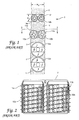
- FIG. 1 a diagrammatic representation of a segment of the human spinal column generally referred to by the letter S is shown.
- the segment of the spinal column S comprises several vertebrae V and a disc space D between two adjacent vertebrae V.
- Various cylindrical threaded spinal fusion implants, each having different diameters, are shown inserted across the disc space D.
- each implant 10a and 10b protrudes from the sides of the spinal column S and could cause severe and perhaps mortal damage to the patient as delicate and vital structures lie adjacent to that area of the spinal column S such that the use of two cylindrical spinal fusion implants 10a and 10b would not be desirable.
- spinal fusion implant 12a would have a diameter that is significantly greater than the height H s of the disc space D, such that the vertebrae V would have to be substantially bored out to accommodate the large diameter of the spinal fusion implant 12a. As a result, a large part of the vertebrae V would be removed, and thus the overall structural integrity of the vertebrae V would be substantially weakened.
- spinal fusion implants 14 a and 14b each having a sufficiently sized diameter such that when placed side-by-side in the disc space D, the combined overall width of the spinal fusion implants 14a and 14b just fills the transverse width W s of the spinal column S, the diameter of each of the spinal fusion implants 14a and 14b will not be sufficient to cross the disc space D to engage the vertebrae V. Therefore, while the spinal fusion implants 14a and 14b will not protrude from the sides of the spinal column S, the spinal fusion implants 14a and 14b cannot reach and engage the bone of the vertebrae V and thus cannot function to stabilize the adjacent vertebrae V.
- FIG 2 a top plan view, taken along line 2--2 of Figure 1 with the upper vertebrae V removed, of two cylindrical threaded implants 10a and 10b placed across the disc space D is shown.
- the threaded implants 10a and 10b have an external thread 11a and 11b which must have a minimum height that is proportional to the size of the threaded implant to be effective.
- the thread 11a and 11b of the threaded implants 10a and 10b converts torque to linear motion, such that the threads 11a and 11b need to be of a sufficient height to overcome the resistance of the material, such as bone, in which the threaded implants 10a and 10b are being inserted, such resistance being proportional to the surface area and diameter of each of threaded implant 10a and 10b.
- each threaded implant 10a and 10b is such that when two threaded implants 10a and 10b are implanted across the disc space D and into the adjacent vertebrae V, there must be a minimum distance between the two threaded implants 10a and 10b to allow for the height of the threads 11a and 11b. This would be true even if the threads 11a and 11b were interdigitated the threaded implants 10a and 10b would still be offset by at least the height of the thread of at least one of the threaded implants 10a and 10b. Such a minimum distance between the two threaded implants 10a and 10b increases the combined overall width of the two threaded implants 10a and 10b when inserted.
- a cylindrical spinal fusion implant in order for a cylindrical spinal fusion implant to be used in the spinal fusion process where the height H s of the disc space D between two adjacent vertebrae V is large relative to its width W s , it is necessary to have an implant that can be implanted adjacent to a second of its kind in closer contact than is possible with threaded implants, while still providing for an implant surface that will provide mechanical stability in engagement to the adjacent vertebrae V.
- the use of a cylindrical implant is desirable as it is easy to prepare the recipient site by drilling a cylindrical hole across the disc space D and into the adjacent vertebrae V.
- the curved surface of the cylindrical holes drilled into the vertebrae V have increased surface area compared to a flat surface and also provides for the possibility of tight congruency when the cylindrical hole is fitted with an implant having corresponding cylindrical portions of matched diameter.
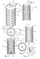
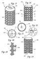
- the spinal fusion implant 100 has a substantially cylindrical configuration having a thin outer wall 112 surrounding an internal chamber 114 and a longitudinal central axis L.
- the exterior of the spinal fusion implant 100 comprises surface roughenings that provide a surface suitable for engaging the vertebrae V to stabilize the spinal fusion implant 100 across the disc space D and into the adjacent vertebrae V once surgically implanted.
- the surface roughenings comprise a plurality of ratchetings 120 along the circumference of said spinal fusion implant. Each of the plurality of ratchetings 120 has a bone engaging edge 122 and an angled segment 124.
- Each of the plurality of ratchetings 120 has a height that is substantially less than the height of a requisite thread for a cylindrical threaded implant of the same size.
- the requisite height of the thread is proportional to the surface area and diameter of the implant and must be sufficient to pull a cylindrical implant having a diameter sufficient to cross the disc space D through a material as dense as bone.
- the ratchetings 120 have a height that is significantly less than the requisite height of a thread of a same sized threaded implant since the spinal fusion implant 100 is implanted across the disc space D and into the adjacent vertebrae V by linear advancement.
- the spinal fusion implant 100 may be pushed into the cylindrical disc space D by direct, linear advancement since it requires no thread to pull it forward through the spine. As no torque is required to advance the spinal fusion implant 100 there is no minimum requisite height of the surface roughenings. The only surface feature necessary is that which gives the spinal fusion implant 100 stability once implanted.
- the ratchetings 120 may face in one direction, the direction in which the spinal fusion implant 100 is inserted, and function to prevent the spinal fusion implant 100 from backing out of the disc space D in a direction opposite to the direction of insertion once inserted between the two adjacent vertebrae V.
- the ratchetings 120 urge the spinal fusion implant 100 forward against the unremoved bone of the vertebrae V. Since implants generally want to back out along the same path in which they are inserted, such as repeated movement of the patient's body over time and which would cause some other design of implant to come loose (e.g. cause a threaded cylindrical implant to possibly unscrew), the ratchetings 120 tend to urge the spinal fusion implant 100 forward against the solid unremoved bone further resisting dislodgement and controlling motion resulting in an exceedingly stable implantation.
- the bone engaging edges 122 of the ratchetings 120 that have a height at a highest point measured from the root diameter of the spinal fusion implant 100 that is approximately 0.35 mm. In this manner the spinal fusion implant 100 may be placed beside a second of its kind at a distance of approximately 0.7 mm apart or if offset even closer, substantially reducing the combined overall width of the two spinal fusion implants 100 once surgically implanted.
- the ratchetings 120 may have a height in the range of 0.25 - 1.5 mm, with the preferred height range being 0.35 - 0.75 mm.
- two spinal fusion implants 100a and 100b are shown inserted across the disc space D having the same dimensions of the disc space D shown in Figure 2.
- the two spinal fusion implants 100a and 100b have a decreased overall combined width when compared to two threaded spinal fusion implants placed side by side previously described and illustrated in Figure 2.
- the decreased combined overall width of the two spinal fusion implants 100a and 100b is the difference between the root and major diameters of the spinal fusion implants 100a and 100b and is achieved by utilizing surface roughenings such as ratchetings 120 for stability.
- the surface roughenings allow the two spinal fusion implants 100a and 100b to come into considerably closer approximation to one another and require less total transverse width for their insertion than is possible for two threaded cylindrical implants having identical root diameters because of the requisite thread height of such threaded implants. Reducing the offset between implants allows for the uses of larger diameter implants which can then still fit within the transverse width W s of the spinal column and achieve more substantial engagement into the adjacent vertebrae V.
- FIG. 7 a cross section of the spinal fusion implant 100 is shown wherein the wall 112 has openings 128 passing therethrough to communicate with the internal chamber 114.
- the internal chamber 114 may be filled with bone material or any natural or artificial bone growth material or fusion promoting material such that bone growth occurs from the vertebrae V through the openings 128 to the material within internal chamber 114.
- the openings 128 have been shown in the drawings as being circular, it is appreciated that the openings 128 may have any shape, size, or form suitable for use in a spinal fusion implant without departing from the scope of the present invention. Also, the number of openings may be varied or no openings may be present on the spinal fusion implant.
- the spinal fusion implant 100 has a cap 130 with a thread 132 that threadably attaches to one end of the spinal fusion implant 100.
- the edge 136 acts as an additional ratcheting 120 to further stabilize the spinal fusion implant 100 once it is implanted across the disc space D.
- the cap 130 is removable to provide access to the internal chamber 114, such that the internal chamber 114 can be filled and hold any natural or artificial osteoconductive, osteoinductive, osteogenic, or other fusion enhancing material.
- Some examples of such materials are bone harvested from the patient, or bone growth inducing material such as, but not limited to, hydroxyapatite, hydroxyapatite tricalcium phosphate; or bone morphogenic protein.
- the cap 130 and/or the spinal fusion implant 100 itself is made of material appropriate for human implantation such as titanium and/or may be made of, and/or filled and/or coated with a bone ingrowth inducing material such as, but not limited to, hydroxyapatite or hydroxyapatite tricalcium phosphate or any other osteoconductive, osteoinductive, osteogenic, or other fusion enhancing material.
- a bone ingrowth inducing material such as, but not limited to, hydroxyapatite or hydroxyapatite tricalcium phosphate or any other osteoconductive, osteoinductive, osteogenic, or other fusion enhancing material.
- the cap 130a may be "bullet"-shaped to facilitate insertion.
- the cap 130a has at its greatest diameter a diameter equal to the root diameter of the spinal fusion implant 100 such that no additional ratchetings 120 are formed.
- the spinal fusion implant 100 has an engagement means at one end in the form of a rectangular slot 140 for engaging a driver instrument having a removable engagement means for intimately engaging the rectangular slot 140.
- a threaded portion of the driver instrument which in one embodiment extends as a rod through a hollow tubular member and can be rotationally controlled, screws into a threaded aperture 142 In the slot 140 and binds the implant 100 and the driver instrument together.
- the spinal fusion implant 100 may be then introduced through a hollow cylindrical tube and driven into the cylindrical hole that has been drilled across the disc space D.
- the implant driver instrument may then be impacted by a mallet, or similar device, to linearly advance the spinal fusion implant 100 across the disc space D.
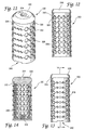
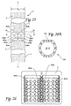
- the spinal fusion implant 200 is similar to the spinal fusion implant 100 except that the openings 228 are bisected by the bone engaging edge 222 of the plurality of ratchetings 220. In this manner, the bone engaging edges are interrupted by the openings 228 to provide a "tooth-like" edge that engages the bone of the vertebrae V and creates an interference fit to prevent the' backing out of the implant 200 once inserted. It is appreciated that the number of openings 228 and the number of bone engaging edges 222 may be varied and that the opening 228 can be placed in any orientation relative to the ratchetings 220 or other surface roughening without departing from the scope of the present invention.
- the spinal fusion implant 300 has a substantially cylindrical configuration having surface roughenings for stabilizing the implant 300 within the intervertebral space D.
- the surface roughenings comprise a surface knurling 320 such as, but not limited to, the diamond-shaped bone engaging pattern shown.
- the spinal fusion implant 300 may have surface knurling 320 throughout the entire external surface of the spinal fusion implant 300, throughout only a portion of the external surface, or any combination thereof, without departing from the scope of the present invention.
- surface knurling 320 is preferred as it produces an exceedingly high interference fit with the bone of the vertebrae V and resists motion equally in all directions and without the tendency to urge itself forward.
- two spinal fusion implants 300a and 300b may be placed side-by-side across the disc space D having the same dimensions of the disc space D shown in Figure 2, such that the two spinal fusion implants 300a and 300b are touching each other and thus reducing the overall combined width of the two spinal implants 300a and 300b to the minimum distance possible with a substantially cylindrical implant having a roughened surface.
- two cylindrical spinal fusion implants 300a and 300b having a sufficient diameter to cross the height H s of the disc space D can be placed across the disc space D without exceeding the transverse width W s of the spinal column S.
- the spinal fusion implants 300a and 300b are inserted by linear advancement as described above for spinal fusion implant 100.
- spinal fusion implants 300a and 300b may be placed closer together to substantially reduce the overall combined width of two such implants.
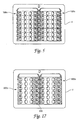
- the spinal fusion implant 400 has a similar configuration to that of the spinal fusion implant 200, except that it comprises a partially cylindrical member having arcuate portions 402 and 404 which are arcs of the same circle with portions of its outer wall 405 that are flattened so as to present a first flat side 406 and a second flat side 408.
- the spinal fusion implant 400 has a major diameter M equal to the distance between two diametrically opposite non-flattened segments, such as arcuate portions 402 and 404 which are arcs of the same circle.
- the width W i of the spinal fusion implant 400 is equal to the distance between a flattened segment and a point diametrically opposite the flattened segment, such as the distance between the first and second flat sides 406 and 408.
- FIG. 25 a diagrammatic representation of a segment of a spinal column S comprising several vertebrae V is shown having two spinal fusion implants 400a and 400b inserted across the disc space D between the two adjacent vertebrae V.
- the spinal fusion implants 400a and 400b are identical and each has a first arcuate portion 402a and 402b, respectively; a second arcuate portion 404a and 404b, respectively; a first flat side 406a and 406b, respectively; and a second flat side 408a and 408b, respectively.
- the spinal fusion implants 400a and 400b are implanted across the disc space D with the second flat side 408a of spinal fusion implant 400a facing and adjacent to the first flat side 408b of spinal fusion implant 400b such that the combined overall width of the two spinal fusion implants 400a and 400b is less than twice the maximum diameter M of the implants.
- the spinal fusion implants 400a and 400b are inserted by linear advancement as described above for spinal fusion implant 100.
- two partially overlapping cylindrical holes are drilled across the disc space D and into the adjacent vertebrae V.
- the holes are drilled sufficiently overlapping to allow the two spinal fusion implants 400a and 400b to be implanted with the flat sides perpendicular to the plane of the disc space D, the disc space D being in a plane perpendicular to the longitudinal vertical axis A of the spinal column S as shown in Figure 25.
- the spinal fusion implants 400a and 400b may be inserted separately such that once a first spinal fusion implant 400a is inserted across the disc space D, a second spinal fusion implant 400b is driven across the disc space D so that the flat side 402 or 404 of each spinal fusion implant 400 are adjacent to each other and are touching. In this manner, the two spinal fusion implants 400a and 400b are implanted across the disc space U and engage the bone of the adjacent vertebrae V without exceeding the transverse width W s of the spinal column S.
- the two spinal fusion implants 400a and 400b may be implanted across the disc space D simultaneously by placing them adjacent and facing each other, in the orientation described above, prior to implantation. The two spinal fusion implants 400a and 400b are then linearly advanced into the drilled holes across the disc space D.
- the effect of having first and second flat sides 406 and 408 is that the overall width W i of the spinal fusion implant 400 is substantially reduced while the height of the spinal fusion implant 400 remains the maximum diameter M of the cylindrical portion of the spinal fusion implant 400.
- each spinal fusion implant 400a and 400b engages the bone of the adjacent vertebrae V while the combined width of the two spinal fusion implant 100 does not exceed the transverse width W s of the spinal column S.
- the advantages of placing two cylindrical implants side by side across the disc space D may be obtained without exceeding the width W s of the spinal column S.
- the two spinal fusion implants 400a and 400b can be inserted across the disc space D, having the same dimensions as the disc space D shown in Figure 2, and can be placed much closer together as a result of the first flat side 408b placed adjacent to the second flat side 408a while continuing to engage the adjacent vertebrae V.
- the spinal fusion implant 400 has a hollow internal central chamber 414 and has a series of openings 428 passing through the outer wall 405 and into the central chamber 414 of the spinal fusion implant 400.
- the openings 428 may also be present on the first and second flat sides 406 and 408.
- Said openings 428 while shown as round holes for example, may be any other workable configuration consistent with their purpose and may include, but is not limited to, ovals, slots, grooves and holes that are not round as is true for any of the cylindrical implants disclosed above.
- the spinal fusion implant 400' could have only one flat side so as to provide only a first flat side 406'. This configuration is appropriate where the width W i of the spinal fusion implant 400 need only be slightly reduced with respect to its maximum diameter M, to prevent the combined overall width of two such implants from exceeding the transverse width W s of the spinal column S.
- the spinal fusion implant 400 of the present invention has a plurality of ratchetings 420 facing one direction, as described above for spinal fusion implant 100, along the outer surface of the cylindrical portion of the circumference of the spinal fusion implant 400.
- the ratchetings 420 have a bone engaging edges 422 and the angled configuration of the ratchetings 420 provide for a "one-way" insertion of the spinal fusion implant 400 as the movement of the spinal fusion implant 400 in the opposite way is prevented by the engagement or the engaging edges 422 with the vertebrae V.
- the flat sides 402 and 404 are preferably smooth and have a flat surface so as to allow placement in the closest possible proximity of the two spinal fusion implants 400a and 400b.
- the bone engaging edge 422 of each ratcheting 420 bisects the holes 428 to increase the stability of the spinal fusion implant 400 once implanted.
- the spinal fusion implants 100-600 each have an overall length in the range of 20mm to 30mm, with 25mm being preferred, and a maximum diameter M in the range of 14mm to 24mm, with 18mm being preferred when inserted in the lumbar spine from the posterior approach, and 20mm being preferred when inserted in the lumbar spine from the anterior approach.
- the spinal fusion implant 400 is quite appropriate for use in the cervical and thoracic spine as well. In the cervical spine such implants would have a length in the range of 10-18mm preferred 12 mm and a maximum diameter M in the range of 12-20mm, with the preferred diameter being 16mm.
- spinal fusion implants 400-600 have a width W i for use in the cervical spine in the range of 8-16mm, with the preferred width W i being 10-14mm; for use in the lumbar spine in the range of 18-26mm, with the preferred width W s being 18-20mm; and for use in the lumbar spine in the range of 18-26mm, with the preferred width W i being 20-24mm.
- the spinal fusion implant 400 of the present invention has externally the geometrical configuration of a circle with a portion of each side tangentially amputated vertically to form the first and second flat sides 406 and 408.
- the cap 430 extends beyond the narrowest diameter of the wall 412 along the first and second arcuate portions 402 and 404 at the end of the spinal fusion implant 400 and acts as an additional ratcheting 420 with an engaging edge 436.
- the additional ratcheting 420 functions to further increase the stability of the spinal fusion implant 400 once inserted between the adjacent vertebrae V and to further prevent the dislodgement of the spinal fusion implant 400 from the disc space D.
- the cap 430 is flush with the flat sides 406 and 408 to preserve the flat surfaces of flat sides 406 and 408.
- the cap 430 further has a sloping sides 438a and 438b corresponding position with the flat sides 406 and 408 to facilitate insertion of the spinal fusion implant 400 and to permit for close side by side placement of two spinal fusion implants 400.
- the cap 430 can be flush all the way around with the root diameter of the spinal fusion implant 400 to further facilitate insertion for a longer ramp length.
- the spinal fusion implant 400 has surface roughenings such as, but not limited to, ratchetings 420 such that the outer surface of the spinal fusion implant 400 may have a plurality of other surface roughenings to enhance to stability of the spinal fusion implant 400 and to resist dislodgement once implanted across the disc space D.
- the spinal fusion implant 400 may have an irregular outer surface that may be created by blasting or rough casting and the like. Such an irregular surface may be used alone or in combination with other surface roughenings such as ratchetings and/or knurling and as already discussed, the openings 428 may be holes, grooves, slots or other.
- the spinal fusion implant 500 is substantially the same as the spinal fusion implant 400, except that the openings 528 are positioned on the ratcheting 520 such that the openings 528 are positioned between the bone engaging edges 522 and are not bisected by the bone engaging edges 522. In this manner the bone engaging edges 522 are continuous and uninterrupted to engage the bone of the vertebrae V and prevent the backing out of the implant 500 once inserted.
- the spinal fusion implant 600 is substantially identical to the spinal fusion implant 400 described above except that in place of ratchetings 420, it has surface knurling 620 such as, but not limited to, the diamond-shaped bone engaging pattern shown in Figure 40.
- the surface knurling 620 assists in the retaining of the spinal fusion implant 600 once it is inserted across the disc space D between two adjacent vertebrae V. It is recognized that the surface knurling 620 of the implant 600 may be combined with any of a number of other surface roughenings such as, but not limited to, ratchetings to assist in retaining the spinal fusion implant 600 across the disc space D.
- the cap 630 of the spinal fusion implant 600 has sloping sides 660 and 662 corresponding with the first and second flat sides 606 and 608 to facilitate insertion of the spinal fusion implant 600 and to permit for close side by side placement of two spinal fusion implants 600.
- the implant invention may include any and all surface roughening configuration that either increase the surface area or interference fit of the implant and the vertebrae V. It is appreciated that the ratchetings described above for the various embodiments of the spinal fusion implants of the present invention may also comprise a knurled or other surface roughenings in combination with the ratchetings to further enhance the retention of the spinal fusion implant across the disc space D once inserted.
- the spinal fusion implant 700 has surface roughenings comprising of a blasted external surface 701 to provide an engagement surface for the vertebrae V when inserted across the disc space D.
- the spinal fusion implant has a plurality of openings 728, a removable cap 730 with a hex slot 734 for engaging a hex tool.
- FIG. 42 an alternative embodiment of the spinal fusion implant of the present invention generally referred to by the numeral 800 is shown.
- the spinal fusion implant 800 is similar to spinal fusion implant 400 described above except that it has openings in the form of horizontal slots 828 on the flat side 806 and vertical slots 829 on the cylindrical portion of the spinal fusion implant 800.
- the spinal implants of the present invention may have any configuration such that the combined overall width of the two such spinal fusion implants is less than twice the maximum diameter M of those implants without departing from the scope of the present invention.
- a segment of the spinal column S is shown with an alternative embodiment of two spinal fusion implants 900a and 900b inserted across disc space D 1 is shown.
- Spinal fusion implant 900a has a concave surface 902 which is correspondingly shaped for receiving the convex surface 904 of spinal fusion implant 900b.
- the concave surface 902 mates with the convex surface 904 such that the combined overall width of the two spinal fusion implants is less than twice the maximum diameter M of those implants.
- the spinal fusion implant 1000 comprises a first cylindrical portion 1010 and a second cylindrical portion 1012 and may have any of the surface roughenings described above in reference to the embodiments set forth above.
- the spinal fusion implant 1000 is inserted by linear advancement into two overlapping cylindrical holes drilled across the disc space D 2 .
- a first further preferred embodiment of the present invention is a partially cylindrical spinal fusion implant made of a material appropriate for human implantation, said implant comprising a cylinder having a longitudinal central axis and at least a first flat side parallel to said central axis.
- said implant has a plurality of flat sides.
- said implant has a second flat side diametrically opposite said first flat side.
- said implant has an internal chamber.
- This third aspect of the first further preferred embodiment of the present invention forms a second further preferred embodiment of the present invention.
- said internal chamber is capable of containing fusion promoting material.
- said implant comprises a wall surrounding said internal chamber.
- Said wall may have a plurality of openings passing therethrough in communication with said internal chamber.
- said spinal fusion implant has a plurality of openings capable retaining fusion promoting material.
- said implant has a major diameter larger than the disc space between two adjacent vertebrae.
- said spinal fusion implant includes a plurality of surface roughenings for engaging said two adjacent vertebrae and for maintaining said implant in place, said surface roughenings being present on at least a portion of the exterior of said implant.
- Said surface roughenings may include a plurality of ratchetings. Said ratchetings may face one direction. Said surface roughenings may also include knurling.
- said implant comprises a bone ingrowth material.
- said implant has at least one removable cap for closing at least one end of said internal chamber.
- one end of said implant includes an engagement means for engaging instrumentation for the insertion of said implant.
- said cylinder includes first and second diametrically opposed arcuate portions that are arcs of the same circle.
- a third further preferred embodiment of the present invention is a hollow partially cylindrical spinal fusion implant made of a material appropriate for human implantation, comprising: a cylinder having a longitudinal central axis and at least a first flat side parallel to said central axis, said implant having a major diameter larger than the height of the disc space between two adjacent vertebrae and a width measure from said first flat side to a diametrically opposed segment of said cylinder, said width being smaller than said major diameter.
- a fourth further preferred embodiment of the present invention is a hollow cylindrical spinal fusion implant made of a material appropriate for human implantation, comprising:
- said surface roughenings include a plurality of ratchetings. Said ratchetings may face one direction.
- said surface roughenings include knurling.
- said implant comprises a bone ingrowth material.
- said internal chamber is capable of retaining fusion promoting material.
- said plurality of openings are capable of retaining fusion promoting material.
- said implant has an outer diameter larger than the disc space between two adjacent vertebrae to be fused.
- said implant has at least one removable cap for closing at least one end of said internal chamber.
- said implant comprises a fusion promoting material.
- said implant comprises a fusion promoting material.
- a fifth further preferred embodiment of the present invention is a method for inserting a plurality of partially cylindrical spinal fusion implants made of a material appropriate for human implantation, each of said plurality of implants comprising a cylinder having a longitudinal central axis and at least one flat side parallel to said central axis, said implant having a maximum diameter larger than the disc space between two adjacent vertebrae, comprising the steps of: drilling two partially overlapping cylindrical holes across the disc space between the two adjacent vertebrae; inserting a first of said partially cylindrical spinal fusion implants having a first flat side into one of said overlapping cylindrical holes, said first flat side being oriented perpendicular to the plane of said disc space; inserting a second of said partially cylindrical implants having a second flat side into a second of said overlapping holes, said second flat side being adjacent and facing said first flat side of said first implant.
- a sixth further preferred embodiment of the present invention is a method for inserting a plurality of partially cylindrical spinal fusion implants made of a material appropriate for human implantation, each of said plurality of implants comprising a cylinder having a longitudinal central axis and at least one flat side parallel to said central axis, said implant having a diameter larger than the disc space between two adjacent vertebrae, said disc space being in a plane perpendicular to the longitudinal vertical axis of the spinal column, comprising the steps of: drilling two partially overlapping cylindrical holes across the disc space between the two adjacent vertebrae; inserting a first of said partially cylindrical spinal fusion implants having a first flat side into one of said overlapping cylindrical holes, said first flat side being oriented perpendicular to the plane of said disc space; inserting a second of said partially cylindrical implants having a second flat side into a second of said overlapping holes, said second flat side being adjacent and facing said first flat side of the first implant.
- a seventh further preferred embodiment of the present invention is a partially cylindrical spinal fusion implant made of a material appropriate for human implantation, said spinal fusion implant comprising a partially cylindrical portion having an exterior surface configured to be placed in close proximity to a second partially cylindrical spinal fusion implant, said first and second implants when placed together having a combined overall width that is less than the sum of the individual maximum diameters of each of said first and second implants.
Abstract
Description
- This application is a continuation in part of copending application Serial No. 07/968,240 filed on October 29, 1992 which is a continuation of application Serial No. 07/698,674 filed on May 10, 1991 which is a division of application Serial No. 07/205,935 filed on June 3, 1988, now U.S. Patent No. 5,015,246 issued on May 14, 1991. This application is also a continuation in part of copending design patent application Serial No. 29/023,926 filed on June 3, 1994 and design patent application Serial No. 29/023,923 filed on June 3, 1994.
- The present invention relates to artificial spinal fusion implants to be placed across the intervertebral space left after the removal of a damaged spinal disc, and in particular to an improved, at least partially cylindrical, spinal fusion implant for implantation where two threaded cylindrical implants of requisite height would not fit within the transverse width of the spine.
- In the past, Cloward, Wilterberger, Crock, Viche, Bagby, Brantigan, Michelson and others have taught various methods involving the drilling of holes across the disc space between two adjacent vertebrae of the spine for the purpose of causing an interbody spinal fusion. Cloward taught placing a dowel of bone within that drilled hole for the purpose of bridging the defect and to be incorporated into the fusion. Viche taught the threading of that bone dowel. Bagby taught the placing of the bone graft into a metal bucket otherwise smooth on its surface, except for rows of radially placed holes communicative to the interior of the basket and to the bone graft. The Bagby device was disclosed as capable of being used in a horse. Brantigan taught the use of inert blocks preferably made of metal and having that metal at its external surface imitate the porosity of bone. Brantigan theorized that the bone dowel could be replaced entirely with a metal plug, that, while not itself active in the fusion, would nevertheless serve to support the vertebrae from within the disc space while allowing fusion to occur around it.
- U.S. Patent No. 3,844,601 issued to Ma et al. on November 19, 1974, teaches a method and instrumentation for preparing rectangular spaces across the disc space into the adjacent vertebrae and for preparing a rectangular graft of the bone itself that is inserted in the rectangular spaces.
- U.S. Patent No. 4,743,256 issued to Brantigan on May 10, 1988 teaches the use of an inert artificial spacer in the shape of a rectangle in place of using a rectangular bone graft as taught by Ma et al.
- U.S. Patent No. 4,878,915 issued to Brantigan on November 7, 1989, teaches the use of fully cylindrical inert implants for use in interbody spinal fusion. Such implants do not participate in the bone fusion process but act as inert spacers and allow for the growth of bone to the outer surfaces of the implants.
- U.S. Patent No. 4,834,757 issued to Brantigan on May 30, 1989, teaches a rectangular shaped, hollow spinal fusion implant for use in lieu of a rectangular bone graft or Brantigan's earlier artificial inert spacer.
- U.S. Patent No. 5,015,247 issued to Michelson on May 14, 1991, teaches the use of a thin-walled, highly perforated, threaded, hollow cylindrical implant closed or closable at both ends, so as to be compressably loaded with bone or other fusion promoting materials. Additionally, the Michelson device may then be coated with a bone production inducing chemical such as hydroxyapatite. The Michelson patent also discloses an improved method of drilling holes across the disc space and into the two adjacent vertebrae and safely installing cylindrical implants such that the entire surgical procedure may be conducted through a hollow cylindrical tube. The hollow cylindrical tube may be left in place throughout the surgical procedure and serves to hold the adjacent vertebrae in place relative to each other, permits the guarded drilling of the holes across the disc space, and permits the insertion of the implant through that same tube into the hole drilled across the disc space and into the adjacent vertebrae.
- As regards this method of performing interbody spinal fusion using essentially cylindrical threaded implants, a special problem arises (see Figure 1) when an attempt is made to place two cylindrical implants (considered to be the preferred number as it is a much more stable construct and has more surface area than a single implant placed centrally) side-by-side across a disc space and into the two adjacent vertebrae where the height of the disc space is such that it requires an implant of a diameter so large to penetrate into and significantly engage each of the adjacent vertebrae that it is no longer possible to place two such implants side-by-side and to still have them contained within the transverse width of the spine. If an attempt is made to remedy the problem by using smaller diameter implants placed side-by-side such that both would then be able to fit within the transverse width of the spine, then the implants would be of insufficient height to adequately engage the bone. If an attempt is made to remedy the problem by abandoning the side-by-side double implant construct in favor of a single, centrally placed implant, then where the implant is sufficiently large enough to occupy a sufficient portion of the transverse width of the disc space to promote firm stability, its vertical height and excursion into the vertebrae would be so severe that if any two consecutive disc spaces were to be operated upon, the vertebrae in between would be cut in half.
- U.S. Patent No, 5,055,104 issued to Ray on October 8, 1991 ("Ray Patent") discloses an implant comprising a helical coil without wall members that is assembled after the coils are placed in the disc space between the vertebrae, which supposedly can then be removed after the vertebrae have become fused together. The Ray implant is defective and unworkable in that it is incapable of being used in the manner in which it is described as it is not possible to insert into hard bone an isolated helical coil without any wall members to support such a coil, which could would be analogous structurally to a slinky, (See Ray Patent, Figures 1 and 7). Further, the Ray implant is unduly complex, because it would require the difficult, if not impossible, task of assembly within the disc space. Figure 3 of the Ray Patent clearly reveals that Ray does not teach the use of a truncated cylindrical implant, but merely teaches the use of a truncated, helical coil appearing as a sharpened spring totally lacking any wall member which could be considered cylindrical. Therefore, Ray teaches only the use of an isolated thread which can only be inserted by rotation and cannot be linearly advanced.
- If the overwhelming obstacles of the impossibility of inserting an isolated thread without wall members and the problem of the assembly within the disc space could be overcome, then the Ray implant would still be unsafe for its intended purpose as it would be at high risk of spontaneous disassembly and mechanical failure. Further, there would be insufficient room to safely rotate such a device for insertion as it is the very lack of such room that requires the use of a device having a decreased transverse width.
- There is therefore, the need for a spinal fusion implant that is capable of being inserted into a hole drilled across the disc space between two adjacent vertebrae and partially into the two adjacent vertebrae such that the spinal fusion implant is capable of fitting within the transverse width of the spine when placed side-by-side next to a second of its kind.
- The present invention is an improved interbody spinal fusion implant that is capable of being inserted into a hole drilled across the disc space between two adjacent vertebrae and into the two adjacent vertebrae such that the spinal fusion implant is capable of fitting within the transverse width of the spine when placed side-by-side next to a second of its kind. The spinal fusion implant of the present invention comprises a thin-wall, multi-perforate, cylinder or partial cylinder, made of material appropriate for human implantation and having preferably, but not necessarily, one closed end and one end capable of being closed, such than an internal chamber can be filled and hold any natural or artificial osteoconductive, osteoinductive, osteogenic, or other fusion enhancing material. The spinal fusion implant of the present invention relies on roughenings of the outer surface to enhance its stability. Depending on the dimension of the transverse width of the spine in which the spinal fusion implant is being inserted, the spinal fusion implant of the present invention may have one or more flat sides to reduce the width of the spinal fusion implant. The spinal fusion implant of the present invention incorporates at its rear end, an engagement means to facilitate insertion or extraction of the implant, preferably at its rear end. The implant of the present invention may be made of, filled with and/or coated with fusion promoting substances. Further, the spinal fusion implant of the present invention does not require rotation for its insertion and can be seated by linear advancement.
- The spinal fusion implant of the present invention is generally effective, and is safer and more effective than the cylindrical implants of the prior art for the special instance when it is desirable to insert two implants side-by-side into cylindrically prepared channels, and where the height of the disc space between two adjacent vertebrae is so great relative to the transverse width of the spine, that two implants of the requisite height will not fit within the transverse width of the spine. Prior art has taught those knowledgeable in the art of spinal surgery, that the likelihood of obtaining a spinal fusion is proportionate to three factors: 1) the surface area of the implant 2) the quality and quantity of the graft material and 3) the stability of the fusion construct. The spinal fusion implant of the present invention increases each of these three factors by making it possible to use two implants side-by-side across a disc space that would otherwise lack sufficient width to accept more than one.
- The spinal fusion implant of the present invention is more efficacious than the prior art on an individual implant basis for the following reasons:
- 1. Increased surface area. The spinal fusion implant of the present invention, because of its surface roughenings has greater surface area for engaging the adjacent vertebrae than an implant with smooth external surfaces. The presence or absence of holes does not materially affect this, so far as the holes are filled with material effectively contributing to the area of contact at the surface. The arced portions of the partially cylindrical implant of the present invention are in contact with the adjacent vertebrae and provide a greater surface area than is possible with a flat portion from a non-cylindrical implant.
- 2. The quantity and quality of graft material presented. As the spinal fusion implant of the present invention is not screwed in, it need not be constructed to resist the torquing therewith associated. Thus, the implant of the present invention may be thinner walled and thereby, for a given diameter, have greater internal volume. The spinal fusion implant of the present invention has arced portions making the implant stronger in compression than an implant lacking upper and lower curved supporting surfaces such that the wall of the implant can be relatively thinner than such implants. A thinner wall is easier for bone to grow through. Also, the interpore bridges may be smaller allowing for greater porosity and thereby greater exposure to the internal graft material. Further, the spinal fusion implant of the present invention may be constructed of and/or coated with, and/or loaded with a variety of materials and/or chemical substrates known to actively participate in the bone fusion process. As the spinal fusion implant of the present invention offers greater surface area, and greater internal volume for its outside diameter, it offers the opportunity for presenting a greater surface area and volume of these fusion materials.
- 3. The implant of the present invention offers greater stability than the prior art implants. The least stable implants are the implants lacking surface roughenings. Surface holes increase implant stability by increasing the interference of the implant to the opposed surfaces. The spinal fusion implant of the present invention is a further improvement over the prior art in that the surface roughenings of the spinal fusion implant of the present invention resist motion in all directions. Further, all implants are subject to the possibility of backing out, by retracing the path by which they were inserted. However, the spinal fusion implant of the present invention can have a surface configured to urge the spinal fusion implant forward as to offer increased resistance against such undesirable backward migration. Further, the arced portions of the implant of the present invention provide a greater support area to better distribute the compression forces through the vertebrae.
-
- The spinal fusion implant of the present invention is easier to use as it occupies less space, does not require pre-tapping, and can be inserted without the need to rotate an instrument within the closed confines of the spinal wound. Further, the spinal fusion implant of the present invention is easier to insert than implants lacking upper and lower curved supporting surfaces that are arcs of the same circle and which implants are to be inserted across the disc space and into the adjacent vertebrae as it is easier to prepare a round hole than a square hole, as a round hole can be drilled in a single step.
- It is an object of the present invention to provide an improved interbody spinal fusion implant such that it is possible to place two such implants side-by-side across a disc space and into two adjacent vertebrae in close approximation to each other and within the transverse width of the spine, where the transverse width of the spine would have otherwise been insufficient relative to the required implant height to have allowed for the accommodation of two prior art cylindrical threaded implants.
- It is another object of the present invention to provide a spinal fusion implant that is easier to insert, and does not require tapping prior to implantation.
- It is yet another object of the present invention to provide a spinal fusion implant that is safer, in which there is not need to run sharp threads near delicate structures.
- It is still another object of the present invention to provide a spinal fusion implant that is faster to implant between adjacent vertebrae via linear advancement as opposed to rotational advancement.
- It is yet another object of the present invention to provide a method for implanting partially cylindrical implants having at least one flat side.
- These and other objects of the present invention will be apparent from a review of the accompanying drawings and the following detailed description of the drawings.
-
- Figure 1 is a diagrammatic representation of a segment of the human spinal column comprising several vertebrae with various cylindrical threaded implants inserted across the disc space and into the two adjacent vertebrae to illustrate the problems encountered by those implants.
- Figure 2 is a top plan view along
lines 2--2 of Figure 1 with the top vertebrae removed, of two cylindrical threaded implants illustrating the minimum distance possible between the two threaded implants when placed beside each other across the disc space. - Figure 3 is a perspective side view of an embodiment of the spinal fusion implant of the present invention having surface roughenings in the form of ratchetings.
- Figure 4 is a first side elevational view of the spinal fusion implant of Figure 3.
- Figure 5 is a top plan view of two spinal fusion implants of Figure 3 illustrating the minimum distance possible between the two implants when placed beside each other across the disc space.
- Figure 6 is a second side elevational view of the spinal fusion implant of Figure 3.
- Figure 7 is a cross sectional view along
lines 7--7 of the spinal fusion implant of Figure 6. - Figure 8 is a cross sectional view along
lines 8--8 of the spinal fusion implant of Figure 6. - Figure 9 is a top end view of the spinal fusion implant of Figure 3.
- Figure 10 is a bottom end view of the spinal fusion implant of Figure 3.
- Figure 11 is a side perspective view of an alternative embodiment of the spinal fusion implant of the present invention.
- Figure 12 is a first side elevational view of the spinal fusion implant of Figure 11.
- Figure 13 is a second side elevational view of the spinal fusion implant of Figure 11.
- Figure 14 is a cross sectional view along
lines 14--14 of the spinal fusion implant of Figure 13. - Figure 15 is a perspective side view of an alternative embodiment of the spinal fusion implant of the present invention having surface roughenings in the form of knurling.
- Figure 16 is a first side elevational view of the spinal fusion implant of Figure 15.
- Figure 17 is a top plan view of two spinal fusion implants of Figure 15 illustrating the minimum distance possible between the two implant when placed beside each other across the disc space.
- Figure 18 is an enlarged fragmentary view along
line 18 of Figure 16 showing the surface configuration of the implant of Figure 15. - Figure 19 is a second side elevational view of the spinal fusion implant of Figure 15.
- Figure 20 is a cross sectional view along
lines 20--20 of the spinal fusion implant of Figure 16. - Figure 21 is a top end view of the spinal fusion implant of Figure 15.
- Figure 22 is a bottom end view of the spinal fusion implant of Figure 15.
- Figure 23 is a perspective side view of an alternative embodiment of the spinal fusion implant of the present invention having flat sides and surface roughenings in the form of ratchetings.
- Figure 24 is a first side elevational view of the spinal fusion implant of Figure 23.
- Figure 25 is a diagrammatic representation of a segment of the human spinal column showing two implants of Figure 23 the present invention inserted within the spine.
- Figure 26 is a top plan view along
lines 26--26 of Figure 25 with the top vertebrae removed, illustrating the minimum distance possible between two spinal fusion implants of Figure 23 placed beside each other across the disc space. - Figure 27 is a top end view of the spinal fusion implant of Figure 23.
- Figure 28 is a bottom end view of the spinal fusion implant of Figure 23.
- Figure 29 is a second side elevational view of the spinal fusion implant of Figure 23.
- Figure 30 is a cross sectional view along
lines 30--30 of the spinal fusion implant of Figure 29. - Figure 30A is a cross sectional view of an alternative embodiment of the spinal fusion implant of the present invention having only one flat side.
- Figure 31 is a perspective side view of an alternative embodiment of the spinal fusion implant of the present invention having flat sides and surface roughenings in the form of ratchetings.
- Figure 32 is a first side elevational view of the spinal fusion implant of Figure 31.
- Figure 33 is a second side elevational view of the spinal fusion implant of Figure 31.
- Figure 34 is a cross sectional view along
lines 34--34 of the spinal fusion implant of Figure 33. - Figure 35 is a cross sectional view along
lines 35--35 of the spinal fusion implant of Figure 33. - Figure 36 is a perspective side view of an alternative embodiment of the spinal fusion implant of the present invention having flat sides and having surface roughenings in the form of knurling.
- Figure 37 is a first side elevational view of the spinal fusion implant of Figure 36.
- Figure 38 is a second side elevational view of the spinal fusion implant of Figure 36.
- Figure 39 is a cross sectional view along
lines 39--39 of the spinal fusion implant of Figure 38. - Figure 40 is an enlarged fragmentary view along
line 40 of Figure 37 showing the surface configuration of the spinal fusion implant of Figure 36. - Figure 41 is a perspective side view of an alternative embodiment of the spinal fusion implant of the present invention having surface roughenings comprising of a blasted external surface.
- Figure 42 is a perspective side view of an alternative embodiment of the spinal fusion implant of the present invention having flat sides and openings in the form of vertical and horizontal slots.
- Figure 43 is an elevational side view of a segment of the spinal column with an alternative embodiment of two spinal fusion implants of the present invention having corresponding concave and convex sides inserted across one disc space and an alternative embodiment of a single spinal fusion implant of the present invention having a two cylindrical portions inserted across one disc space.
-
- Referring to Figure 1, a diagrammatic representation of a segment of the human spinal column generally referred to by the letter S is shown. The segment of the spinal column S comprises several vertebrae V and a disc space D between two adjacent vertebrae V. Various cylindrical threaded spinal fusion implants, each having different diameters, are shown inserted across the disc space D.
- When the height Hs of the disc space D is so large that two cylindrical implants, such as
spinal fusion implants spinal implants implant spinal fusion implants - If instead of two
spinal fusion implants spinal fusion implant 12a were to be used having a sufficient diameter to provide for stability and fusion, then the implant would penetrate deeply into the adjacent vertebrae V. Thespinal fusion implant 12a would have a diameter that is significantly greater than the height Hs of the disc space D, such that the vertebrae V would have to be substantially bored out to accommodate the large diameter of thespinal fusion implant 12a. As a result, a large part of the vertebrae V would be removed, and thus the overall structural integrity of the vertebrae V would be substantially weakened. This is especially a problem when a secondspinal fusion implant 12b identical tospinal fusion implant 12a is placed across disc space D on the other side of the same vertebrae V such that twospinal fusion implants - Conversely, if two cylindrical implants such as
spinal fusion implants spinal fusion implants spinal fusion implants spinal fusion implants spinal fusion implants - Referring to Figure 2, a top plan view, taken along
line 2--2 of Figure 1 with the upper vertebrae V removed, of two cylindrical threadedimplants implants external thread thread implants threads implants implant implant implants implants threads threads implants implants implants implants - Therefore, in order for a cylindrical spinal fusion implant to be used in the spinal fusion process where the height Hs of the disc space D between two adjacent vertebrae V is large relative to its width Ws, it is necessary to have an implant that can be implanted adjacent to a second of its kind in closer contact than is possible with threaded implants, while still providing for an implant surface that will provide mechanical stability in engagement to the adjacent vertebrae V. The use of a cylindrical implant is desirable as it is easy to prepare the recipient site by drilling a cylindrical hole across the disc space D and into the adjacent vertebrae V. The curved surface of the cylindrical holes drilled into the vertebrae V have increased surface area compared to a flat surface and also provides for the possibility of tight congruency when the cylindrical hole is fitted with an implant having corresponding cylindrical portions of matched diameter.
- Referring to Figures 3-10, an embodiment of the spinal fusion implant of the present invention, is shown and generally referred to by the numeral 100. The
spinal fusion implant 100 has a substantially cylindrical configuration having a thinouter wall 112 surrounding aninternal chamber 114 and a longitudinal central axis L. The exterior of thespinal fusion implant 100 comprises surface roughenings that provide a surface suitable for engaging the vertebrae V to stabilize thespinal fusion implant 100 across the disc space D and into the adjacent vertebrae V once surgically implanted. In one embodiment of thespinal fusion implant 100, the surface roughenings comprise a plurality ofratchetings 120 along the circumference of said spinal fusion implant. Each of the plurality ofratchetings 120 has abone engaging edge 122 and anangled segment 124. - Each of the plurality of
ratchetings 120 has a height that is substantially less than the height of a requisite thread for a cylindrical threaded implant of the same size. As a thread is a simple device for converting torque to linear advancement, the requisite height of the thread is proportional to the surface area and diameter of the implant and must be sufficient to pull a cylindrical implant having a diameter sufficient to cross the disc space D through a material as dense as bone. In contrast, theratchetings 120 have a height that is significantly less than the requisite height of a thread of a same sized threaded implant since thespinal fusion implant 100 is implanted across the disc space D and into the adjacent vertebrae V by linear advancement. Thespinal fusion implant 100 may be pushed into the cylindrical disc space D by direct, linear advancement since it requires no thread to pull it forward through the spine. As no torque is required to advance thespinal fusion implant 100 there is no minimum requisite height of the surface roughenings. The only surface feature necessary is that which gives thespinal fusion implant 100 stability once implanted. - Moreover, the
ratchetings 120 may face in one direction, the direction in which thespinal fusion implant 100 is inserted, and function to prevent thespinal fusion implant 100 from backing out of the disc space D in a direction opposite to the direction of insertion once inserted between the two adjacent vertebrae V. Theratchetings 120 urge thespinal fusion implant 100 forward against the unremoved bone of the vertebrae V. Since implants generally want to back out along the same path in which they are inserted, such as repeated movement of the patient's body over time and which would cause some other design of implant to come loose (e.g. cause a threaded cylindrical implant to possibly unscrew), theratchetings 120 tend to urge thespinal fusion implant 100 forward against the solid unremoved bone further resisting dislodgement and controlling motion resulting in an exceedingly stable implantation. - The
bone engaging edges 122 of theratchetings 120 that have a height at a highest point measured from the root diameter of thespinal fusion implant 100 that is approximately 0.35 mm. In this manner thespinal fusion implant 100 may be placed beside a second of its kind at a distance of approximately 0.7 mm apart or if offset even closer, substantially reducing the combined overall width of the twospinal fusion implants 100 once surgically implanted. Theratchetings 120 may have a height in the range of 0.25 - 1.5 mm, with the preferred height range being 0.35 - 0.75 mm. - Referring to Figure 5, two
spinal fusion implants spinal fusion implants spinal fusion implants spinal fusion implants ratchetings 120 for stability. The surface roughenings allow the twospinal fusion implants - Referring to Figure 7, a cross section of the
spinal fusion implant 100 is shown wherein thewall 112 hasopenings 128 passing therethrough to communicate with theinternal chamber 114. Theinternal chamber 114 may be filled with bone material or any natural or artificial bone growth material or fusion promoting material such that bone growth occurs from the vertebrae V through theopenings 128 to the material withininternal chamber 114. While theopenings 128 have been shown in the drawings as being circular, it is appreciated that theopenings 128 may have any shape, size, or form suitable for use in a spinal fusion implant without departing from the scope of the present invention. Also, the number of openings may be varied or no openings may be present on the spinal fusion implant. - Referring to Figures 8 and 9, the
spinal fusion implant 100 has acap 130 with athread 132 that threadably attaches to one end of thespinal fusion implant 100. Once thecap 130 is attached to thespinal fusion implant 100, theedge 136 acts as anadditional ratcheting 120 to further stabilize thespinal fusion implant 100 once it is implanted across the disc space D. - The
cap 130 is removable to provide access to theinternal chamber 114, such that theinternal chamber 114 can be filled and hold any natural or artificial osteoconductive, osteoinductive, osteogenic, or other fusion enhancing material. Some examples of such materials are bone harvested from the patient, or bone growth inducing material such as, but not limited to, hydroxyapatite, hydroxyapatite tricalcium phosphate; or bone morphogenic protein. Thecap 130 and/or thespinal fusion implant 100 itself is made of material appropriate for human implantation such as titanium and/or may be made of, and/or filled and/or coated with a bone ingrowth inducing material such as, but not limited to, hydroxyapatite or hydroxyapatite tricalcium phosphate or any other osteoconductive, osteoinductive, osteogenic, or other fusion enhancing material. - Referring to Figure 4, alternatively the
cap 130a may be "bullet"-shaped to facilitate insertion. Thecap 130a has at its greatest diameter a diameter equal to the root diameter of thespinal fusion implant 100 such that noadditional ratchetings 120 are formed. - Referring to Figure 10, the
spinal fusion implant 100 has an engagement means at one end in the form of arectangular slot 140 for engaging a driver instrument having a removable engagement means for intimately engaging therectangular slot 140. A threaded portion of the driver instrument, which in one embodiment extends as a rod through a hollow tubular member and can be rotationally controlled, screws into a threadedaperture 142 In theslot 140 and binds theimplant 100 and the driver instrument together. Once affixed to the implant driver instrument, thespinal fusion implant 100 may be then introduced through a hollow cylindrical tube and driven into the cylindrical hole that has been drilled across the disc space D. The implant driver instrument may then be impacted by a mallet, or similar device, to linearly advance thespinal fusion implant 100 across the disc space D. Once thespinal fusion implant 100 is inserted across the disc space D, theratchetings 120, engage the bone of the vertebrae V and the implant driver instrument is detached from thespinal fusion implant 100. The procedure for drilling the holes across the disc space D and instrumentation pertaining thereto are described in copending Application Serial No. 08/074,781 filed on June 10, 1993, incorporated herein by reference. - Referring to Figures 11-14, an alternative embodiment of the spinal fusion implant of the present invention, generally referred to by the numeral 200 is shown. The
spinal fusion implant 200 is similar to thespinal fusion implant 100 except that theopenings 228 are bisected by thebone engaging edge 222 of the plurality ofratchetings 220. In this manner, the bone engaging edges are interrupted by theopenings 228 to provide a "tooth-like" edge that engages the bone of the vertebrae V and creates an interference fit to prevent the' backing out of theimplant 200 once inserted. It is appreciated that the number ofopenings 228 and the number ofbone engaging edges 222 may be varied and that theopening 228 can be placed in any orientation relative to theratchetings 220 or other surface roughening without departing from the scope of the present invention. - Referring to Figures 15-19, an alternative embodiment of the spinal fusion implant of the present invention generally referred to by the numeral 300 is shown. The
spinal fusion implant 300 has a substantially cylindrical configuration having surface roughenings for stabilizing theimplant 300 within the intervertebral space D. As shown in Figure 18, the surface roughenings comprise asurface knurling 320 such as, but not limited to, the diamond-shaped bone engaging pattern shown. Thespinal fusion implant 300 may havesurface knurling 320 throughout the entire external surface of thespinal fusion implant 300, throughout only a portion of the external surface, or any combination thereof, without departing from the scope of the present invention. In those circumstances where there is no undrilled bone in the disc space D forward of thespinal fusion implant 300 to resist further forward advancement of the implant,surface knurling 320 is preferred as it produces an exceedingly high interference fit with the bone of the vertebrae V and resists motion equally in all directions and without the tendency to urge itself forward. - Referring to Figure 17, two
spinal fusion implants spinal fusion implants spinal implants spinal fusion implants spinal fusion implants spinal fusion implant 100. Therefore, as no threading is required for the insertion ofspinal fusion implants spinal fusion implants spinal fusion implants - Referring to Figures 23-30, an alternative embodiment of the spinal fusion implant of the present invention is shown and is generally referred to by the numeral 400. The
spinal fusion implant 400 has a similar configuration to that of thespinal fusion implant 200, except that it comprises a partially cylindrical member havingarcuate portions outer wall 405 that are flattened so as to present a firstflat side 406 and a secondflat side 408. - Referring to Figure 28, the
spinal fusion implant 400 has a major diameter M equal to the distance between two diametrically opposite non-flattened segments, such asarcuate portions spinal fusion implant 400 is equal to the distance between a flattened segment and a point diametrically opposite the flattened segment, such as the distance between the first and secondflat sides - Referring to Figure 25, a diagrammatic representation of a segment of a spinal column S comprising several vertebrae V is shown having two
spinal fusion implants spinal fusion implants arcuate portion arcuate portion flat side flat side spinal fusion implants flat side 408a ofspinal fusion implant 400a facing and adjacent to the firstflat side 408b ofspinal fusion implant 400b such that the combined overall width of the twospinal fusion implants spinal fusion implants spinal fusion implant 100. - Prior to implantation, two partially overlapping cylindrical holes are drilled across the disc space D and into the adjacent vertebrae V. The holes are drilled sufficiently overlapping to allow the two
spinal fusion implants - The
spinal fusion implants spinal fusion implant 400a is inserted across the disc space D, a secondspinal fusion implant 400b is driven across the disc space D so that theflat side spinal fusion implant 400 are adjacent to each other and are touching. In this manner, the twospinal fusion implants spinal fusion implants spinal fusion implants - Referring to Figure 28, the effect of having first and second
flat sides spinal fusion implant 400 is substantially reduced while the height of thespinal fusion implant 400 remains the maximum diameter M of the cylindrical portion of thespinal fusion implant 400. - Referring to Figures 25 and 26, as the height of each
spinal fusion implant spinal fusion implant spinal fusion implant 100 does not exceed the transverse width Ws of the spinal column S. As a result, the advantages of placing two cylindrical implants side by side across the disc space D may be obtained without exceeding the width Ws of the spinal column S. Thus, as shown in Figure 26, the twospinal fusion implants flat side 408b placed adjacent to the secondflat side 408a while continuing to engage the adjacent vertebrae V. - As shown in Figure 30, the
spinal fusion implant 400 has a hollow internalcentral chamber 414 and has a series ofopenings 428 passing through theouter wall 405 and into thecentral chamber 414 of thespinal fusion implant 400. Theopenings 428 may also be present on the first and secondflat sides openings 428 while shown as round holes for example, may be any other workable configuration consistent with their purpose and may include, but is not limited to, ovals, slots, grooves and holes that are not round as is true for any of the cylindrical implants disclosed above. - Referring to Figure 30A, it is appreciated that it is also within the scope of the present invention that the spinal fusion implant 400' could have only one flat side so as to provide only a first flat side 406'. This configuration is appropriate where the width Wi of the
spinal fusion implant 400 need only be slightly reduced with respect to its maximum diameter M, to prevent the combined overall width of two such implants from exceeding the transverse width Ws of the spinal column S. - Referring to Figures 23, 24 and 29, the
spinal fusion implant 400 of the present invention has a plurality of ratchetings 420 facing one direction, as described above forspinal fusion implant 100, along the outer surface of the cylindrical portion of the circumference of thespinal fusion implant 400. The ratchetings 420 have abone engaging edges 422 and the angled configuration of the ratchetings 420 provide for a "one-way" insertion of thespinal fusion implant 400 as the movement of thespinal fusion implant 400 in the opposite way is prevented by the engagement or theengaging edges 422 with the vertebrae V. However, theflat sides spinal fusion implants bone engaging edge 422 of each ratcheting 420 bisects theholes 428 to increase the stability of thespinal fusion implant 400 once implanted. - The spinal fusion implants 100-600 each have an overall length in the range of 20mm to 30mm, with 25mm being preferred, and a maximum diameter M in the range of 14mm to 24mm, with 18mm being preferred when inserted in the lumbar spine from the posterior approach, and 20mm being preferred when inserted in the lumbar spine from the anterior approach. The
spinal fusion implant 400 is quite appropriate for use in the cervical and thoracic spine as well. In the cervical spine such implants would have a length in the range of 10-18mm preferred 12 mm and a maximum diameter M in the range of 12-20mm, with the preferred diameter being 16mm. In the thoracic spine such implants would have a length in the range of 16-26mm and a greatest diameter in the range of 14-20mm, with the preferred diameter being 16mm. In addition to the foregoing dimensions, spinal fusion implants 400-600 have a width Wi for use in the cervical spine in the range of 8-16mm, with the preferred width Wi being 10-14mm; for use in the lumbar spine in the range of 18-26mm, with the preferred width Ws being 18-20mm; and for use in the lumbar spine in the range of 18-26mm, with the preferred width Wi being 20-24mm. - Referring to Figures 27 and 28, when viewed on end, the
spinal fusion implant 400 of the present invention has externally the geometrical configuration of a circle with a portion of each side tangentially amputated vertically to form the first and secondflat sides cap 430 extends beyond the narrowest diameter of the wall 412 along the first and secondarcuate portions spinal fusion implant 400 and acts as an additional ratcheting 420 with anengaging edge 436. In this manner, the additional ratcheting 420 functions to further increase the stability of thespinal fusion implant 400 once inserted between the adjacent vertebrae V and to further prevent the dislodgement of thespinal fusion implant 400 from the disc space D. Thecap 430 is flush with theflat sides flat sides cap 430 further has a sloping sides 438a and 438b corresponding position with theflat sides spinal fusion implant 400 and to permit for close side by side placement of twospinal fusion implants 400. Alternatively, thecap 430 can be flush all the way around with the root diameter of thespinal fusion implant 400 to further facilitate insertion for a longer ramp length. - The
spinal fusion implant 400 has surface roughenings such as, but not limited to, ratchetings 420 such that the outer surface of thespinal fusion implant 400 may have a plurality of other surface roughenings to enhance to stability of thespinal fusion implant 400 and to resist dislodgement once implanted across the disc space D. For example, thespinal fusion implant 400 may have an irregular outer surface that may be created by blasting or rough casting and the like. Such an irregular surface may be used alone or in combination with other surface roughenings such as ratchetings and/or knurling and as already discussed, theopenings 428 may be holes, grooves, slots or other. - Referring to Figures 32-35, an alternative embodiment of the spinal fusion implant of the present invention is shown and generally referred to by the numeral 500. The
spinal fusion implant 500 is substantially the same as thespinal fusion implant 400, except that theopenings 528 are positioned on the ratcheting 520 such that theopenings 528 are positioned between thebone engaging edges 522 and are not bisected by the bone engaging edges 522. In this manner thebone engaging edges 522 are continuous and uninterrupted to engage the bone of the vertebrae V and prevent the backing out of theimplant 500 once inserted. - Referring to Figures 36-40, an alternative embodiment of the spinal fusion implant of the present invention is shown and generally referred to by the numeral 600. The
spinal fusion implant 600 is substantially identical to thespinal fusion implant 400 described above except that in place of ratchetings 420, it hassurface knurling 620 such as, but not limited to, the diamond-shaped bone engaging pattern shown in Figure 40. Thesurface knurling 620 assists in the retaining of thespinal fusion implant 600 once it is inserted across the disc space D between two adjacent vertebrae V. It is recognized that thesurface knurling 620 of theimplant 600 may be combined with any of a number of other surface roughenings such as, but not limited to, ratchetings to assist in retaining thespinal fusion implant 600 across the disc space D. - As shown in Figure 36, the
cap 630 of thespinal fusion implant 600 has slopingsides flat sides spinal fusion implant 600 and to permit for close side by side placement of twospinal fusion implants 600. - It is appreciated that the implant invention may include any and all surface roughening configuration that either increase the surface area or interference fit of the implant and the vertebrae V. It is appreciated that the ratchetings described above for the various embodiments of the spinal fusion implants of the present invention may also comprise a knurled or other surface roughenings in combination with the ratchetings to further enhance the retention of the spinal fusion implant across the disc space D once inserted.
- Referring to Figure 41, an alternative embodiment of the spinal fusion implant of the present invention generally referred to by the numeral 700 is shown. The
spinal fusion implant 700 has surface roughenings comprising of a blastedexternal surface 701 to provide an engagement surface for the vertebrae V when inserted across the disc space D. The spinal fusion implant has a plurality ofopenings 728, aremovable cap 730 with ahex slot 734 for engaging a hex tool. - Referring to Figure 42, an alternative embodiment of the spinal fusion implant of the present invention generally referred to by the numeral 800 is shown. The
spinal fusion implant 800 is similar tospinal fusion implant 400 described above except that it has openings in the form ofhorizontal slots 828 on theflat side 806 andvertical slots 829 on the cylindrical portion of thespinal fusion implant 800. - It is appreciated that the spinal implants of the present invention may have any configuration such that the combined overall width of the two such spinal fusion implants is less than twice the maximum diameter M of those implants without departing from the scope of the present invention.
- Referring to Figure 43, a segment of the spinal column S is shown with an alternative embodiment of two
spinal fusion implants Spinal fusion implant 900a has aconcave surface 902 which is correspondingly shaped for receiving theconvex surface 904 ofspinal fusion implant 900b. When the twospinal fusion implants concave surface 902 mates with theconvex surface 904 such that the combined overall width of the two spinal fusion implants is less than twice the maximum diameter M of those implants. As a result, the advantages of placing two implants that are partially cylindrical, with respect to the portion engaging the vertebrae V, side by side across the disc space D may be obtained without exceeding the width Ws of the spinal column S. - Referring still to Figure 43, an alternative embodiment of the spinal fusion implant of the present invention comprising a single
spinach fusion implant 1000 inserted across the disc space D2 of the spinal column S is shown. Thespinal fusion implant 1000 comprises a firstcylindrical portion 1010 and a secondcylindrical portion 1012 and may have any of the surface roughenings described above in reference to the embodiments set forth above. In the preferred embodiment, thespinal fusion implant 1000 is inserted by linear advancement into two overlapping cylindrical holes drilled across the disc space D2. - Further preferred embodiments of the present invention are given in the following paragraphs:
- A first further preferred embodiment of the present invention is a partially cylindrical spinal fusion implant made of a material appropriate for human implantation, said implant comprising a cylinder having a longitudinal central axis and at least a first flat side parallel to said central axis.
- In a first aspect of the first further preferred embodiment of the present invention, said implant has a plurality of flat sides.
- In a second aspect of the first further preferred embodiment of the present invention, said implant has a second flat side diametrically opposite said first flat side.
- In a third aspect of the first further preferred embodiment of the present invention, said implant has an internal chamber. This third aspect of the first further preferred embodiment of the present invention forms a second further preferred embodiment of the present invention.
- In a first aspect of the second further preferred embodiment of the present invention, said internal chamber is capable of containing fusion promoting material.
- In a second aspect of the second further preferred embodiment of the present invention, said implant comprises a wall surrounding said internal chamber. Said wall may have a plurality of openings passing therethrough in communication with said internal chamber.
- In a fourth aspect of the first further preferred embodiment of the present invention, said spinal fusion implant has a plurality of openings capable retaining fusion promoting material.
- In a fifth aspect of the first further preferred embodiment of the present invention, said implant has a major diameter larger than the disc space between two adjacent vertebrae.
- In a sixth aspect of the first further preferred embodiment of the present invention, said spinal fusion implant includes a plurality of surface roughenings for engaging said two adjacent vertebrae and for maintaining said implant in place, said surface roughenings being present on at least a portion of the exterior of said implant. Said surface roughenings may include a plurality of ratchetings. Said ratchetings may face one direction. Said surface roughenings may also include knurling.
- In a seventh aspect of the first further preferred embodiment of the present invention, said implant comprises a bone ingrowth material.
- In a third aspect of the second further preferred embodiment of the present invention, said implant has at least one removable cap for closing at least one end of said internal chamber.
- In an eighth aspect of the first further preferred embodiment of the present invention, one end of said implant includes an engagement means for engaging instrumentation for the insertion of said implant.
- In a ninth aspect of the first further preferred embodiment of the present invention, said cylinder includes first and second diametrically opposed arcuate portions that are arcs of the same circle.
- A third further preferred embodiment of the present invention is a hollow partially cylindrical spinal fusion implant made of a material appropriate for human implantation, comprising: a cylinder having a longitudinal central axis and at least a first flat side parallel to said central axis, said implant having a major diameter larger than the height of the disc space between two adjacent vertebrae and a width measure from said first flat side to a diametrically opposed segment of said cylinder, said width being smaller than said major diameter.
- A fourth further preferred embodiment of the present invention is a hollow cylindrical spinal fusion implant made of a material appropriate for human implantation, comprising:
- a cylindrical member having a wall surrounding an internal chamber, said wall having a plurality of openings passing therethrough in communication with said internal chamber, said implant having a plurality of surface roughenings on the exterior of said cylindrical member for engaging said vertebrae to maintain said implant in place.
-
- In a first aspect of the fourth further preferred embodiment of the present invention, said surface roughenings include a plurality of ratchetings. Said ratchetings may face one direction.
- In a second aspect of the fourth further preferred embodiment of the present invention, said surface roughenings include knurling.
- In a third aspect of the fourth further preferred embodiment of the present invention, said implant comprises a bone ingrowth material.
- In a fourth aspect of the fourth further preferred embodiment of the present invention, said internal chamber is capable of retaining fusion promoting material.
- In a fifth aspect of the fourth further preferred embodiment of the present invention, said plurality of openings are capable of retaining fusion promoting material.
- In a sixth aspect of the fourth further preferred embodiment of the present invention, said implant has an outer diameter larger than the disc space between two adjacent vertebrae to be fused.
- In a seventh aspect of the fourth further preferred embodiment of the present invention, said implant has at least one removable cap for closing at least one end of said internal chamber.
- In an eighth aspect of the fourth further preferred embodiment of the present invention, said implant comprises a fusion promoting material.
- In a tenth aspect of the first further preferred embodiment of the present invention, said implant comprises a fusion promoting material.
- A fifth further preferred embodiment of the present invention is a method for inserting a plurality of partially cylindrical spinal fusion implants made of a material appropriate for human implantation, each of said plurality of implants comprising a cylinder having a longitudinal central axis and at least one flat side parallel to said central axis, said implant having a maximum diameter larger than the disc space between two adjacent vertebrae, comprising the steps of: drilling two partially overlapping cylindrical holes across the disc space between the two adjacent vertebrae; inserting a first of said partially cylindrical spinal fusion implants having a first flat side into one of said overlapping cylindrical holes, said first flat side being oriented perpendicular to the plane of said disc space; inserting a second of said partially cylindrical implants having a second flat side into a second of said overlapping holes, said second flat side being adjacent and facing said first flat side of said first implant.
- A sixth further preferred embodiment of the present invention is a method for inserting a plurality of partially cylindrical spinal fusion implants made of a material appropriate for human implantation, each of said plurality of implants comprising a cylinder having a longitudinal central axis and at least one flat side parallel to said central axis, said implant having a diameter larger than the disc space between two adjacent vertebrae, said disc space being in a plane perpendicular to the longitudinal vertical axis of the spinal column, comprising the steps of: drilling two partially overlapping cylindrical holes across the disc space between the two adjacent vertebrae; inserting a first of said partially cylindrical spinal fusion implants having a first flat side into one of said overlapping cylindrical holes, said first flat side being oriented perpendicular to the plane of said disc space; inserting a second of said partially cylindrical implants having a second flat side into a second of said overlapping holes, said second flat side being adjacent and facing said first flat side of the first implant.
- A seventh further preferred embodiment of the present invention is a partially cylindrical spinal fusion implant made of a material appropriate for human implantation, said spinal fusion implant comprising a partially cylindrical portion having an exterior surface configured to be placed in close proximity to a second partially cylindrical spinal fusion implant, said first and second implants when placed together having a combined overall width that is less than the sum of the individual maximum diameters of each of said first and second implants.
- While the present invention has been described in detail with regard to the preferred embodiments, it is appreciated that other variations of the present invention may be devised which do not depart from the inventive concept and scope of the present invention.
Claims (17)
- A spinal fusion implant made of a material appropriate for human implantation at least in part between two adjacent vertebral bodies, said implant comprising:a non-threaded cylindrical member having an exterior with opposed arcuate portions adapted to be oriented toward the two adjacent vertebral bodies, each of said opposed arcuate portions being arcs of the same circle and having at least one opening passing therethrough to allow bone growth from one of the two adjacent vertebral bodies through said implant to the other of the two adjacent vertebral bodies, said implant having a plurality of surface projections on said exterior of said cylindrical member for engaging the vertebral bodies to maintain said implant in place, wherein said surface projections include a plurality of annular ratchetings defined around the circumference of said cylindrical member adapted to facilitate insertion and resist expulsion of said implant from between the adjacent vertebral bodies.
- The implant of claim 1, wherein said implant has at least one truncated side adapted for side by side placement with a second spinal implant.
- The implant of claim 2, wherein said truncated side is non-linear between said opposed arcuate portions.
- The implant of any one of the above claims, wherein said implant has an outer diameter larger than the disc space between the two adjacent vertebral bodies to be fused.
- The implant of any one of the above claims, further comprising an internal chamber.
- The implant of claim 5, wherein said implant has at least one removable cap for closing at least one end of said internal chamber.
- The implant of claim 6, wherein said cap has a non-circular outer perimeter.
- The implant of any one of the above claims, wherein said ratchetings face one direction.
- The implant of any one of claims 1 to 7, wherein said ratchetings include an angled segment terminating in a bone engaging edge defined around the circumference of said cylindrical member.
- The implant of any one of the above claims, wherein said at least one opening interrupts said ratchetings.
- The implant of any one of the above claims, further comprising a plurality of openings located at least in part between said ratchetings.
- The implant of any one of the above claims, wherein said implant is made of an artificial material.
- The implant of claim 12, wherein said artificial material includes an implant quality metal.
- The implant of any one of the above claims, in combination with a bone growth promoting material.
- The implant of claim 14, wherein said bone growth promoting material includes at least one of bone morphogenetic protein, hydroxyapatite, hydroxyapatite tricalcium phosphate, and bone.
- The implant of any one of the above claims, in combination with an implant driver configured to insert said implant into the spine.
- The implant of any one of the above claims, in combination with a hollow tube having an opening for providing protected access to the disc space and the adjacent vertebral bodies and for guiding the insertion of said implant into the spine.
Applications Claiming Priority (3)
| Application Number | Priority Date | Filing Date | Title |
|---|---|---|---|
| US390131 | 1995-02-17 | ||
| US08/390,131 US5593409A (en) | 1988-06-13 | 1995-02-17 | Interbody spinal fusion implants |
| EP96300757A EP0732093B8 (en) | 1995-02-17 | 1996-02-02 | Interbody spinal fusion implants |
Related Parent Applications (1)
| Application Number | Title | Priority Date | Filing Date |
|---|---|---|---|
| EP96300757A Division EP0732093B8 (en) | 1995-02-17 | 1996-02-02 | Interbody spinal fusion implants |
Publications (2)
| Publication Number | Publication Date |
|---|---|
| EP1525863A2 true EP1525863A2 (en) | 2005-04-27 |
| EP1525863A3 EP1525863A3 (en) | 2007-01-31 |
Family
ID=23541206
Family Applications (2)
| Application Number | Title | Priority Date | Filing Date |
|---|---|---|---|
| EP96300757A Expired - Lifetime EP0732093B8 (en) | 1995-02-17 | 1996-02-02 | Interbody spinal fusion implants |
| EP04025948A Withdrawn EP1525863A3 (en) | 1995-02-17 | 1996-02-02 | Arcuate ratcheted spinal fusion implant |
Family Applications Before (1)
| Application Number | Title | Priority Date | Filing Date |
|---|---|---|---|
| EP96300757A Expired - Lifetime EP0732093B8 (en) | 1995-02-17 | 1996-02-02 | Interbody spinal fusion implants |
Country Status (13)
| Country | Link |
|---|---|
| US (3) | US5593409A (en) |
| EP (2) | EP0732093B8 (en) |
| JP (1) | JP3848392B2 (en) |
| KR (1) | KR960030887A (en) |
| CN (1) | CN1134810A (en) |
| AT (1) | ATE281132T1 (en) |
| CA (2) | CA2168835C (en) |
| DE (1) | DE69633756T2 (en) |
| DK (1) | DK0732093T3 (en) |
| ES (1) | ES2231799T3 (en) |
| PT (1) | PT732093E (en) |
| TR (1) | TR199600134A2 (en) |
| TW (1) | TW365158U (en) |
Cited By (8)
| Publication number | Priority date | Publication date | Assignee | Title |
|---|---|---|---|---|
| US8460380B2 (en) | 2004-02-13 | 2013-06-11 | Franz Copf, JR. | Intervertebral implant and surgical method for spondylodesis of a lumbar vertebral column |
| WO2016085759A1 (en) * | 2014-11-26 | 2016-06-02 | Ex Technology, Llc | Method and apparatus for joint fusion |
| US9814599B2 (en) | 2009-07-09 | 2017-11-14 | R Tree Innovations, Llc | Inter-body implantation system and method |
| US9931224B2 (en) | 2009-11-05 | 2018-04-03 | DePuy Synthes Products, Inc. | Self-pivoting spinal implant and associated instrumentation |
| US10022245B2 (en) | 2012-12-17 | 2018-07-17 | DePuy Synthes Products, Inc. | Polyaxial articulating instrument |
| US10940013B2 (en) | 2007-07-27 | 2021-03-09 | R Tree Innovations, Llc | Interbody implantation system and method |
| US10966843B2 (en) | 2017-07-18 | 2021-04-06 | DePuy Synthes Products, Inc. | Implant inserters and related methods |
| US11045331B2 (en) | 2017-08-14 | 2021-06-29 | DePuy Synthes Products, Inc. | Intervertebral implant inserters and related methods |
Families Citing this family (564)
| Publication number | Priority date | Publication date | Assignee | Title |
|---|---|---|---|---|
| DE20004692U1 (en) * | 2000-03-14 | 2001-07-26 | Sofamor Danek Gmbh | Vertebral implant for screwing into an intervertebral space |
| US6770074B2 (en) * | 1988-06-13 | 2004-08-03 | Gary Karlin Michelson | Apparatus for use in inserting spinal implants |
| AU7139994A (en) | 1988-06-13 | 1995-01-03 | Karlin Technology, Inc. | Apparatus and method of inserting spinal implants |
| US6923810B1 (en) * | 1988-06-13 | 2005-08-02 | Gary Karlin Michelson | Frusto-conical interbody spinal fusion implants |
| US5772661A (en) * | 1988-06-13 | 1998-06-30 | Michelson; Gary Karlin | Methods and instrumentation for the surgical correction of human thoracic and lumbar spinal disease from the antero-lateral aspect of the spine |
| US6123705A (en) | 1988-06-13 | 2000-09-26 | Sdgi Holdings, Inc. | Interbody spinal fusion implants |
| US7534254B1 (en) | 1988-06-13 | 2009-05-19 | Warsaw Orthopedic, Inc. | Threaded frusto-conical interbody spinal fusion implants |
| US7491205B1 (en) * | 1988-06-13 | 2009-02-17 | Warsaw Orthopedic, Inc. | Instrumentation for the surgical correction of human thoracic and lumbar spinal disease from the lateral aspect of the spine |
| US5609635A (en) * | 1988-06-28 | 1997-03-11 | Michelson; Gary K. | Lordotic interbody spinal fusion implants |
| US5895427A (en) * | 1989-07-06 | 1999-04-20 | Sulzer Spine-Tech Inc. | Method for spinal fixation |
| US5769897A (en) * | 1991-12-13 | 1998-06-23 | Haerle; Anton | Synthetic bone |
| DE19917696A1 (en) * | 1999-04-20 | 2000-10-26 | Karlheinz Schmidt | Biological restoration agent, e.g. for filling bone defects, comprising a carrier coated with or including an active complex of structural, recruiting, adhesion and growth or maturation components |
| CA2551185C (en) * | 1994-03-28 | 2007-10-30 | Sdgi Holdings, Inc. | Apparatus and method for anterior spinal stabilization |
| US5674296A (en) * | 1994-11-14 | 1997-10-07 | Spinal Dynamics Corporation | Human spinal disc prosthesis |
| US6758849B1 (en) | 1995-02-17 | 2004-07-06 | Sdgi Holdings, Inc. | Interbody spinal fusion implants |
| ES2161865T3 (en) * | 1995-03-08 | 2001-12-16 | Synthes Ag | INTERVERTEBRAL IMPLANT |
| EP1504732B1 (en) * | 1995-03-27 | 2007-05-23 | Warsaw Orthopedic, Inc. | Spinal fusion implant |
| US6206922B1 (en) * | 1995-03-27 | 2001-03-27 | Sdgi Holdings, Inc. | Methods and instruments for interbody fusion |
| US6245072B1 (en) | 1995-03-27 | 2001-06-12 | Sdgi Holdings, Inc. | Methods and instruments for interbody fusion |
| US5782919A (en) | 1995-03-27 | 1998-07-21 | Sdgi Holdings, Inc. | Interbody fusion device and method for restoration of normal spinal anatomy |
| US6143031A (en) * | 1995-10-20 | 2000-11-07 | Synthes (U.S.A.) | Intervertebral implant with compressible shaped hollow element |
| US5814084A (en) * | 1996-01-16 | 1998-09-29 | University Of Florida Tissue Bank, Inc. | Diaphysial cortical dowel |
| US5766253A (en) * | 1996-01-16 | 1998-06-16 | Surgical Dynamics, Inc. | Spinal fusion device |
| DE29600879U1 (en) * | 1996-01-19 | 1996-03-28 | Howmedica Gmbh | Spinal implant |
| CA2199462C (en) * | 1996-03-14 | 2006-01-03 | Charles J. Winslow | Method and instrumentation for implant insertion |
| US6111164A (en) * | 1996-06-21 | 2000-08-29 | Musculoskeletal Transplant Foundation | Bone graft insert |
| US5895426A (en) * | 1996-09-06 | 1999-04-20 | Osteotech, Inc. | Fusion implant device and method of use |
| FR2753368B1 (en) | 1996-09-13 | 1999-01-08 | Chauvin Jean Luc | EXPANSIONAL OSTEOSYNTHESIS CAGE |
| US5782832A (en) * | 1996-10-01 | 1998-07-21 | Surgical Dynamics, Inc. | Spinal fusion implant and method of insertion thereof |
| US6063088A (en) * | 1997-03-24 | 2000-05-16 | United States Surgical Corporation | Method and instrumentation for implant insertion |
| US5968098A (en) * | 1996-10-22 | 1999-10-19 | Surgical Dynamics, Inc. | Apparatus for fusing adjacent bone structures |
| KR20000052740A (en) * | 1996-10-23 | 2000-08-25 | 에스디지아이 홀딩스 인코포레이티드 | Spinal spacer |
| US20050165483A1 (en) * | 2004-01-27 | 2005-07-28 | Ray Eddie F.Iii | Bone grafts |
| US6416515B1 (en) * | 1996-10-24 | 2002-07-09 | Spinal Concepts, Inc. | Spinal fixation system |
| JP2002514100A (en) | 1996-10-24 | 2002-05-14 | スピナル コンセプツ,インク. | Method and apparatus for fixing a spine |
| US6190414B1 (en) | 1996-10-31 | 2001-02-20 | Surgical Dynamics Inc. | Apparatus for fusion of adjacent bone structures |
| US6602293B1 (en) * | 1996-11-01 | 2003-08-05 | The Johns Hopkins University | Polymeric composite orthopedic implant |
| DE19652608C1 (en) * | 1996-12-18 | 1998-08-27 | Eska Implants Gmbh & Co | Prophylaxis implant against fractures of osteoporotically affected bone segments |
| US5961554A (en) * | 1996-12-31 | 1999-10-05 | Janson; Frank S | Intervertebral spacer |
| US5836948A (en) | 1997-01-02 | 1998-11-17 | Saint Francis Medical Technologies, Llc | Spine distraction implant and method |
| US7306628B2 (en) * | 2002-10-29 | 2007-12-11 | St. Francis Medical Technologies | Interspinous process apparatus and method with a selectably expandable spacer |
| US7201751B2 (en) * | 1997-01-02 | 2007-04-10 | St. Francis Medical Technologies, Inc. | Supplemental spine fixation device |
| US6902566B2 (en) * | 1997-01-02 | 2005-06-07 | St. Francis Medical Technologies, Inc. | Spinal implants, insertion instruments, and methods of use |
| US6712819B2 (en) | 1998-10-20 | 2004-03-30 | St. Francis Medical Technologies, Inc. | Mating insertion instruments for spinal implants and methods of use |
| US7101375B2 (en) * | 1997-01-02 | 2006-09-05 | St. Francis Medical Technologies, Inc. | Spine distraction implant |
| US20020143331A1 (en) * | 1998-10-20 | 2002-10-03 | Zucherman James F. | Inter-spinous process implant and method with deformable spacer |
| US7959652B2 (en) | 2005-04-18 | 2011-06-14 | Kyphon Sarl | Interspinous process implant having deployable wings and method of implantation |
| US6451019B1 (en) | 1998-10-20 | 2002-09-17 | St. Francis Medical Technologies, Inc. | Supplemental spine fixation device and method |
| US5860977A (en) | 1997-01-02 | 1999-01-19 | Saint Francis Medical Technologies, Llc | Spine distraction implant and method |
| US6514256B2 (en) | 1997-01-02 | 2003-02-04 | St. Francis Medical Technologies, Inc. | Spine distraction implant and method |
| US6156038A (en) * | 1997-01-02 | 2000-12-05 | St. Francis Medical Technologies, Inc. | Spine distraction implant and method |
| US6068630A (en) | 1997-01-02 | 2000-05-30 | St. Francis Medical Technologies, Inc. | Spine distraction implant |
| US5728159A (en) * | 1997-01-02 | 1998-03-17 | Musculoskeletal Transplant Foundation | Serrated bone graft |
| US6695842B2 (en) | 1997-10-27 | 2004-02-24 | St. Francis Medical Technologies, Inc. | Interspinous process distraction system and method with positionable wing and method |
| US6796983B1 (en) | 1997-01-02 | 2004-09-28 | St. Francis Medical Technologies, Inc. | Spine distraction implant and method |
| ES2268267T3 (en) * | 1997-02-11 | 2007-03-16 | Warsaw Orthopedic, Inc. | PREVIOUS CERVICAL PLATE FOR UNIQUE TYPE LOCK DEVICE. |
| WO1998034556A1 (en) * | 1997-02-11 | 1998-08-13 | Michelson Gary K | Skeletal plating system |
| US6120506A (en) * | 1997-03-06 | 2000-09-19 | Sulzer Spine-Tech Inc. | Lordotic spinal implant |
| CA2287523C (en) | 1997-04-25 | 2006-04-18 | Stryker France S.A. | Two-part intersomatic implant |
| US6045579A (en) | 1997-05-01 | 2000-04-04 | Spinal Concepts, Inc. | Adjustable height fusion device |
| US6641614B1 (en) | 1997-05-01 | 2003-11-04 | Spinal Concepts, Inc. | Multi-variable-height fusion device |
| DE19720241B4 (en) * | 1997-05-15 | 2005-12-29 | Eska Implants Gmbh & Co. | Interbody fusion implant |
| US5876457A (en) | 1997-05-20 | 1999-03-02 | George J. Picha | Spinal implant |
| US6149651A (en) * | 1997-06-02 | 2000-11-21 | Sdgi Holdings, Inc. | Device for supporting weak bony structures |
| US6585770B1 (en) | 1997-06-02 | 2003-07-01 | Sdgi Holdings, Inc. | Devices for supporting bony structures |
| US5897556A (en) * | 1997-06-02 | 1999-04-27 | Sdgi Holdings, Inc. | Device for supporting weak bony structures |
| US6033438A (en) | 1997-06-03 | 2000-03-07 | Sdgi Holdings, Inc. | Open intervertebral spacer |
| US5928243A (en) | 1997-07-16 | 1999-07-27 | Spinal Concepts, Inc. | Pedicle probe and depth gage |
| US5910315A (en) * | 1997-07-18 | 1999-06-08 | Stevenson; Sharon | Allograft tissue material for filling spinal fusion cages or related surgical spaces |
| US6454769B2 (en) | 1997-08-04 | 2002-09-24 | Spinal Concepts, Inc. | System and method for stabilizing the human spine with a bone plate |
| US6030389A (en) | 1997-08-04 | 2000-02-29 | Spinal Concepts, Inc. | System and method for stabilizing the human spine with a bone plate |
| US6241771B1 (en) | 1997-08-13 | 2001-06-05 | Cambridge Scientific, Inc. | Resorbable interbody spinal fusion devices |
| US6053921A (en) | 1997-08-26 | 2000-04-25 | Spinal Concepts, Inc. | Surgical cable system and method |
| US5964769A (en) | 1997-08-26 | 1999-10-12 | Spinal Concepts, Inc. | Surgical cable system and method |
| US6168631B1 (en) * | 1997-08-29 | 2001-01-02 | Kinetikos Medical, Inc. | Subtalar implant system and method for insertion and removal |
| US6004326A (en) * | 1997-09-10 | 1999-12-21 | United States Surgical | Method and instrumentation for implant insertion |
| US5865848A (en) * | 1997-09-12 | 1999-02-02 | Artifex, Ltd. | Dynamic intervertebral spacer and method of use |
| NZ503429A (en) * | 1997-09-17 | 2001-10-26 | Osteotech Inc | Fusion implant device formed of bone and to be located in spine |
| US6511509B1 (en) | 1997-10-20 | 2003-01-28 | Lifenet | Textured bone allograft, method of making and using same |
| EP1027004B1 (en) | 1997-10-27 | 2007-12-12 | St. Francis Medical Technologies, Inc. | Spine distraction implant |
| US20010001129A1 (en) * | 1997-12-10 | 2001-05-10 | Mckay William F. | Osteogenic fusion device |
| US6146420A (en) * | 1997-12-10 | 2000-11-14 | Sdgi Holdings, Inc. | Osteogenic fusion device |
| US6648916B1 (en) | 1997-12-10 | 2003-11-18 | Sdgi Holdings, Inc. | Osteogenic fusion device |
| US6348058B1 (en) | 1997-12-12 | 2002-02-19 | Surgical Navigation Technologies, Inc. | Image guided spinal surgery guide, system, and method for use thereof |
| US6086613A (en) | 1997-12-23 | 2000-07-11 | Depuy Acromed, Inc. | Spacer assembly for use in spinal surgeries |
| US6143033A (en) * | 1998-01-30 | 2000-11-07 | Synthes (Usa) | Allogenic intervertebral implant |
| US6986788B2 (en) * | 1998-01-30 | 2006-01-17 | Synthes (U.S.A.) | Intervertebral allograft spacer |
| USRE38614E1 (en) | 1998-01-30 | 2004-10-05 | Synthes (U.S.A.) | Intervertebral allograft spacer |
| US7087082B2 (en) * | 1998-08-03 | 2006-08-08 | Synthes (Usa) | Bone implants with central chambers |
| US6224631B1 (en) * | 1998-03-20 | 2001-05-01 | Sulzer Spine-Tech Inc. | Intervertebral implant with reduced contact area and method |
| US6241729B1 (en) * | 1998-04-09 | 2001-06-05 | Sdgi Holdings, Inc. | Method and instrumentation for posterior interbody fusion |
| US6241769B1 (en) | 1998-05-06 | 2001-06-05 | Cortek, Inc. | Implant for spinal fusion |
| US6171339B1 (en) * | 1998-05-19 | 2001-01-09 | Sulzer Spine-Tech Inc. | Multi-lumen spinal implant guide and method |
| US6368325B1 (en) | 1998-05-27 | 2002-04-09 | Nuvasive, Inc. | Bone blocks and methods for inserting bone blocks into intervertebral spaces |
| WO1999060956A1 (en) | 1998-05-27 | 1999-12-02 | Nuvasive, Inc. | Interlocking spinal inserts |
| US6290724B1 (en) | 1998-05-27 | 2001-09-18 | Nuvasive, Inc. | Methods for separating and stabilizing adjacent vertebrae |
| US6126689A (en) | 1998-06-15 | 2000-10-03 | Expanding Concepts, L.L.C. | Collapsible and expandable interbody fusion device |
| US6086593A (en) | 1998-06-30 | 2000-07-11 | Bonutti; Peter M. | Method and apparatus for use in operating on a bone |
| ATE363877T1 (en) * | 1998-07-22 | 2007-06-15 | Warsaw Orthopedic Inc | SCREWED CYLINDRICAL MULTIDISCOID SINGLE OR MULTIPLE NETWORK PLATE PROSTHESIS |
| US20060241763A1 (en) * | 1998-08-03 | 2006-10-26 | Synthes (Usa) | Multipiece bone implant |
| DE69916280T2 (en) | 1998-08-03 | 2005-05-25 | Synthes Ag Chur, Chur | INTERVERTEBRAL allograft DISTANZSTÜCK |
| US6099531A (en) * | 1998-08-20 | 2000-08-08 | Bonutti; Peter M. | Changing relationship between bones |
| FR2782632B1 (en) * | 1998-08-28 | 2000-12-29 | Materiel Orthopedique En Abreg | EXPANSIBLE INTERSOMATIC FUSION CAGE |
| JP2002524141A (en) * | 1998-09-04 | 2002-08-06 | スパイナル ダイナミックス コーポレイション | Peanut spectacle-shaped thoracolumbar disc prosthesis containing multiple discs |
| AU5813599A (en) * | 1998-09-04 | 2000-03-27 | Spinal Dynamics Corporation | Cylindrical hemi-lunar parallel array threaded disc prosthesis |
| US6117174A (en) * | 1998-09-16 | 2000-09-12 | Nolan; Wesley A. | Spinal implant device |
| US6958149B2 (en) * | 1998-10-06 | 2005-10-25 | Stryker Corporation | Repair of larynx, trachea, and other fibrocartilaginous tissues |
| US6652534B2 (en) | 1998-10-20 | 2003-11-25 | St. Francis Medical Technologies, Inc. | Apparatus and method for determining implant size |
| US6652527B2 (en) | 1998-10-20 | 2003-11-25 | St. Francis Medical Technologies, Inc. | Supplemental spine fixation device and method |
| US7029473B2 (en) * | 1998-10-20 | 2006-04-18 | St. Francis Medical Technologies, Inc. | Deflectable spacer for use as an interspinous process implant and method |
| US7189234B2 (en) | 1998-10-20 | 2007-03-13 | St. Francis Medical Technologies, Inc. | Interspinous process implant sizer and distractor with a split head and size indicator and method |
| EP1123054A4 (en) | 1998-10-21 | 2006-06-21 | Roger P Jackson | Spinal fusion apparatus and method |
| US6174311B1 (en) | 1998-10-28 | 2001-01-16 | Sdgi Holdings, Inc. | Interbody fusion grafts and instrumentation |
| US6074423A (en) * | 1998-11-02 | 2000-06-13 | Lawson; Kevin Jon | Safer more X-ray transparent spinal implant |
| US6126688A (en) * | 1998-12-21 | 2000-10-03 | Surgical Dynamics Inc. | Apparatus for fusion of adjacent bone structures |
| AU764981B2 (en) * | 1999-01-11 | 2003-09-04 | Warsaw Orthopedic, Inc. | Intervertebral spacers with side wall accessible interior cavity |
| AU2003266465B2 (en) * | 1999-01-11 | 2006-12-14 | Warsaw Orthopedic, Inc. | Intervertebral Spacers with Side Wall Accessible Interior Cavity |
| US6547823B2 (en) | 1999-01-22 | 2003-04-15 | Osteotech, Inc. | Intervertebral implant |
| US6325827B1 (en) * | 1999-02-01 | 2001-12-04 | Blacksheep Technologies, Inc. | Intervertebral implant |
| US6086589A (en) * | 1999-02-02 | 2000-07-11 | Spineology, Inc. | Method and device for fixing spondylolisthesis posteriorly |
| AU761818C (en) | 1999-02-04 | 2004-05-27 | Warsaw Orthopedic, Inc. | Methods and instrumentation for vertebral interbody fusion |
| US6743234B2 (en) | 1999-02-04 | 2004-06-01 | Sdgi Holdings, Inc. | Methods and instrumentation for vertebral interbody fusion |
| AU2870200A (en) | 1999-02-04 | 2000-08-25 | Sdgi Holdings, Inc. | Improved interbody fusion device with anti-rotation features |
| AU772682B2 (en) * | 1999-02-04 | 2004-05-06 | Warsaw Orthopedic, Inc. | Highly-mineralized osteogenic sponge compositions, and uses thereof |
| US6648895B2 (en) | 2000-02-04 | 2003-11-18 | Sdgi Holdings, Inc. | Methods and instrumentation for vertebral interbody fusion |
| US6241770B1 (en) * | 1999-03-05 | 2001-06-05 | Gary K. Michelson | Interbody spinal fusion implant having an anatomically conformed trailing end |
| CA2363254C (en) | 1999-03-07 | 2009-05-05 | Discure Ltd. | Method and apparatus for computerized surgery |
| WO2000054821A1 (en) * | 1999-03-16 | 2000-09-21 | Regeneration Technologies, Inc. | Molded implants for orthopedic applications |
| DE60024979T2 (en) * | 1999-04-07 | 2006-08-24 | Howmedica Osteonics Corp. | FUSION CAGE WITH LOW PROFILE AND INTRODUCTION DEVICE |
| US6442814B1 (en) | 1999-04-23 | 2002-09-03 | Spinal Concepts, Inc. | Apparatus for manufacturing a bone dowel |
| US6557226B1 (en) | 1999-04-23 | 2003-05-06 | Michael E. Landry | Apparatus for manufacturing a bone dowel |
| AU776806B2 (en) * | 1999-05-05 | 2004-09-23 | Warsaw Orthopedic, Inc. | Nested interbody spinal fusion implants |
| AU4988700A (en) * | 1999-05-05 | 2000-11-17 | Gary K. Michelson | Spinal fusion implants with opposed locking screws |
| US7094239B1 (en) * | 1999-05-05 | 2006-08-22 | Sdgi Holdings, Inc. | Screws of cortical bone and method of manufacture thereof |
| US6520991B2 (en) | 1999-05-11 | 2003-02-18 | Donald R. Huene | Expandable implant for inter-vertebral stabilization, and a method of stabilizing vertebrae |
| US6214050B1 (en) | 1999-05-11 | 2001-04-10 | Donald R. Huene | Expandable implant for inter-bone stabilization and adapted to extrude osteogenic material, and a method of stabilizing bones while extruding osteogenic material |
| AU770261B2 (en) | 1999-06-04 | 2004-02-19 | Warsaw Orthopedic, Inc. | Artificial disc implant |
| US6520996B1 (en) | 1999-06-04 | 2003-02-18 | Depuy Acromed, Incorporated | Orthopedic implant |
| US6277149B1 (en) | 1999-06-08 | 2001-08-21 | Osteotech, Inc. | Ramp-shaped intervertebral implant |
| WO2000074607A1 (en) * | 1999-06-08 | 2000-12-14 | Osteotech, Inc. | Keyed intervertebral dowel |
| FR2897259B1 (en) * | 2006-02-15 | 2008-05-09 | Ldr Medical Soc Par Actions Si | INTERSOMATIC TRANSFORAMINAL CAGE WITH INTERBREBAL FUSION GRAFT AND CAGE IMPLANTATION INSTRUMENT |
| DE60030989T2 (en) | 1999-08-26 | 2007-05-24 | Warsaw Orthopedic, Inc., Warsaw | DEVICE FOR IMPLANTING FUSION CAGE |
| US6464727B1 (en) | 1999-09-01 | 2002-10-15 | Hugh R. Sharkey | Intervertebral spacer implant |
| US6527773B1 (en) * | 1999-10-07 | 2003-03-04 | Osteotech, Inc. | Cervical dowel and insertion tool |
| JP4326134B2 (en) * | 1999-10-20 | 2009-09-02 | ウォーソー・オーソペディック・インコーポレーテッド | Method and apparatus for performing a surgical procedure |
| US6592624B1 (en) | 1999-11-24 | 2003-07-15 | Depuy Acromed, Inc. | Prosthetic implant element |
| DE19957339C2 (en) * | 1999-11-29 | 2002-03-28 | Franz Copf | Cage element, as well as set of cage elements |
| US6827740B1 (en) * | 1999-12-08 | 2004-12-07 | Gary K. Michelson | Spinal implant surface configuration |
| US7115143B1 (en) | 1999-12-08 | 2006-10-03 | Sdgi Holdings, Inc. | Orthopedic implant surface configuration |
| WO2001049220A1 (en) * | 1999-12-30 | 2001-07-12 | Osteotech, Inc. | Intervertebral implants |
| US6331179B1 (en) | 2000-01-06 | 2001-12-18 | Spinal Concepts, Inc. | System and method for stabilizing the human spine with a bone plate |
| US6447512B1 (en) | 2000-01-06 | 2002-09-10 | Spinal Concepts, Inc. | Instrument and method for implanting an interbody fusion device |
| DE60110375T2 (en) * | 2000-02-04 | 2006-03-02 | Michelson, Gary Karlin, Los Angeles | EXPANDABLE INTERSPINAL FUSION IMPLANT |
| AU783173B2 (en) * | 2000-02-04 | 2005-09-29 | Warsaw Orthopedic, Inc. | Expandable push-in interbody spinal fusion implant |
| US6500205B1 (en) * | 2000-04-19 | 2002-12-31 | Gary K. Michelson | Expandable threaded arcuate interbody spinal fusion implant with cylindrical configuration during insertion |
| US6716247B2 (en) | 2000-02-04 | 2004-04-06 | Gary K. Michelson | Expandable push-in interbody spinal fusion implant |
| US6814756B1 (en) | 2000-02-04 | 2004-11-09 | Gary K. Michelson | Expandable threaded arcuate interbody spinal fusion implant with lordotic configuration during insertion |
| US6709458B2 (en) * | 2000-02-04 | 2004-03-23 | Gary Karlin Michelson | Expandable push-in arcuate interbody spinal fusion implant with tapered configuration during insertion |
| EP1645248B8 (en) * | 2000-02-04 | 2010-06-16 | Warsaw Orthopedic, Inc. | Expandable interbody spinal fusion implant having pivotally attached blocker |
| US7182781B1 (en) * | 2000-03-02 | 2007-02-27 | Regeneration Technologies, Inc. | Cervical tapered dowel |
| AR027685A1 (en) * | 2000-03-22 | 2003-04-09 | Synthes Ag | METHOD AND METHOD FOR CARRYING OUT |
| US6436141B2 (en) | 2000-04-07 | 2002-08-20 | Surgical Dynamics, Inc. | Apparatus for fusing adjacent bone structures |
| US6821298B1 (en) * | 2000-04-18 | 2004-11-23 | Roger P. Jackson | Anterior expandable spinal fusion cage system |
| US6350283B1 (en) * | 2000-04-19 | 2002-02-26 | Gary K. Michelson | Bone hemi-lumbar interbody spinal implant having an asymmetrical leading end and method of installation thereof |
| US7462195B1 (en) | 2000-04-19 | 2008-12-09 | Warsaw Orthopedic, Inc. | Artificial lumbar interbody spinal implant having an asymmetrical leading end |
| FR2808995B1 (en) | 2000-05-18 | 2003-02-21 | Aesculap Sa | INTERSOMATIC CAGE WITH UNIFIED GRAFT |
| US6635086B2 (en) | 2000-05-30 | 2003-10-21 | Blacksheep Technologies Incorporated | Implant for placement between cervical vertebrae |
| USD501555S1 (en) | 2000-06-12 | 2005-02-01 | Ortho Development Corporation | Implant |
| US6579318B2 (en) * | 2000-06-12 | 2003-06-17 | Ortho Development Corporation | Intervertebral spacer |
| WO2002002022A1 (en) * | 2000-06-30 | 2002-01-10 | Stephen Ritland | Polyaxial connection device and method |
| US7018416B2 (en) * | 2000-07-06 | 2006-03-28 | Zimmer Spine, Inc. | Bone implants and methods |
| US6808537B2 (en) * | 2000-07-07 | 2004-10-26 | Gary Karlin Michelson | Expandable implant with interlocking walls |
| US6852126B2 (en) | 2000-07-17 | 2005-02-08 | Nuvasive, Inc. | Stackable interlocking intervertebral support system |
| WO2002009597A2 (en) * | 2000-08-01 | 2002-02-07 | Regeneration Technologies, Inc. | Diaphysial cortical dowel |
| DE60140004D1 (en) * | 2000-08-08 | 2009-11-05 | Warsaw Orthopedic Inc | DEVICE FOR STEREOTAKTIC IMPLANTATION |
| CA2429246C (en) * | 2000-08-08 | 2011-06-07 | Vincent Bryan | Implantable joint prosthesis |
| US7125380B2 (en) * | 2000-08-08 | 2006-10-24 | Warsaw Orthopedic, Inc. | Clamping apparatus and methods |
| US7601174B2 (en) * | 2000-08-08 | 2009-10-13 | Warsaw Orthopedic, Inc. | Wear-resistant endoprosthetic devices |
| US6447546B1 (en) | 2000-08-11 | 2002-09-10 | Dale G. Bramlet | Apparatus and method for fusing opposing spinal vertebrae |
| US7204851B2 (en) | 2000-08-30 | 2007-04-17 | Sdgi Holdings, Inc. | Method and apparatus for delivering an intervertebral disc implant |
| US20020026244A1 (en) * | 2000-08-30 | 2002-02-28 | Trieu Hai H. | Intervertebral disc nucleus implants and methods |
| DE60115254T2 (en) * | 2000-08-30 | 2006-08-10 | SDGI Holdings, Inc., Wilmington | Disc nucleus implants |
| US7503936B2 (en) * | 2000-08-30 | 2009-03-17 | Warsaw Orthopedic, Inc. | Methods for forming and retaining intervertebral disc implants |
| US6500206B1 (en) * | 2000-09-15 | 2002-12-31 | Donald W. Bryan | Instruments for inserting spinal vertebral implant |
| US6443987B1 (en) | 2000-09-15 | 2002-09-03 | Donald W. Bryan | Spinal vertebral implant |
| AU9282601A (en) * | 2000-09-19 | 2002-04-02 | Sdgi Holdings Inc | Osteogenic fusion devices |
| KR100395253B1 (en) * | 2000-09-28 | 2003-08-21 | (주)태연메디칼 | Backbone fused implant |
| US6692434B2 (en) | 2000-09-29 | 2004-02-17 | Stephen Ritland | Method and device for retractor for microsurgical intermuscular lumbar arthrodesis |
| US7166073B2 (en) * | 2000-09-29 | 2007-01-23 | Stephen Ritland | Method and device for microsurgical intermuscular spinal surgery |
| US6572654B1 (en) | 2000-10-04 | 2003-06-03 | Albert N. Santilli | Intervertebral spacer |
| US20030120274A1 (en) * | 2000-10-20 | 2003-06-26 | Morris John W. | Implant retaining device |
| JP2004512097A (en) | 2000-10-24 | 2004-04-22 | エスディージーアイ・ホールディングス・インコーポレーテッド | Apparatus and method for filling osteogenic material |
| AU2002213404A1 (en) * | 2000-10-24 | 2002-05-06 | Howmedica Osteonics Corp. | Barrel-shaped apparatus for fusing adjacent bone structure |
| AU2002225831A1 (en) | 2000-11-03 | 2002-05-15 | Osteotech, Inc. | Spinal intervertebral implant and method of making |
| US6666891B2 (en) | 2000-11-13 | 2003-12-23 | Frank H. Boehm, Jr. | Device and method for lumbar interbody fusion |
| WO2002038062A2 (en) * | 2000-11-13 | 2002-05-16 | Boehm Frank H Jr | Device and method for lumbar interbody fusion |
| US6454807B1 (en) | 2000-11-30 | 2002-09-24 | Roger P. Jackson | Articulated expandable spinal fusion cage system |
| US20020169507A1 (en) * | 2000-12-14 | 2002-11-14 | David Malone | Interbody spine fusion cage |
| US6520993B2 (en) | 2000-12-29 | 2003-02-18 | Depuy Acromed, Inc. | Spinal implant |
| US7018418B2 (en) * | 2001-01-25 | 2006-03-28 | Tecomet, Inc. | Textured surface having undercut micro recesses in a surface |
| DE60201945T2 (en) * | 2001-02-04 | 2005-12-01 | Michelson, Gary Karlin, Los Angeles | Instrument for introducing and spreading an intervertebral fusion implant |
| US6986772B2 (en) * | 2001-03-01 | 2006-01-17 | Michelson Gary K | Dynamic lordotic guard with movable extensions for creating an implantation space posteriorly in the lumbar spine |
| US6562045B2 (en) | 2001-02-13 | 2003-05-13 | Sdgi Holdings, Inc. | Machining apparatus |
| AU2002244116A1 (en) * | 2001-02-16 | 2002-09-04 | Sulzer Spine-Tech Inc. | Bone implants and methods |
| US20020116064A1 (en) * | 2001-02-21 | 2002-08-22 | Lance Middleton | Apparatus for fusing adjacent bone structures |
| US6673075B2 (en) | 2001-02-23 | 2004-01-06 | Albert N. Santilli | Porous intervertebral spacer |
| US6896680B2 (en) | 2001-03-01 | 2005-05-24 | Gary K. Michelson | Arcuate dynamic lordotic guard with movable extensions for creating an implantation space posteriorly in the lumbar spine |
| EP1418851B1 (en) * | 2001-03-01 | 2012-05-09 | Warsaw Orthopedic, Inc. | Dynamic lordotic guard with movable extensions for creating an implantation space posteriorly in the lumbar spine and method for use thereof |
| US20020138147A1 (en) * | 2001-03-22 | 2002-09-26 | Surgical Dynamics, Inc. | Apparatus for fusing adjacent bone structures |
| US6899734B2 (en) | 2001-03-23 | 2005-05-31 | Howmedica Osteonics Corp. | Modular implant for fusing adjacent bone structure |
| US6989031B2 (en) * | 2001-04-02 | 2006-01-24 | Sdgi Holdings, Inc. | Hemi-interbody spinal implant manufactured from a major long bone ring or a bone composite |
| US6890355B2 (en) | 2001-04-02 | 2005-05-10 | Gary K. Michelson | Artificial contoured spinal fusion implants made of a material other than bone |
| US6582433B2 (en) | 2001-04-09 | 2003-06-24 | St. Francis Medical Technologies, Inc. | Spine fixation device and method |
| US7695521B2 (en) * | 2001-05-01 | 2010-04-13 | Amedica Corporation | Hip prosthesis with monoblock ceramic acetabular cup |
| US20050177238A1 (en) * | 2001-05-01 | 2005-08-11 | Khandkar Ashok C. | Radiolucent bone graft |
| US7776085B2 (en) * | 2001-05-01 | 2010-08-17 | Amedica Corporation | Knee prosthesis with ceramic tibial component |
| DE60230739D1 (en) | 2001-05-01 | 2009-02-26 | Amedica Corp | X-RAY BONE TRANSPLANT |
| FR2824261B1 (en) * | 2001-05-04 | 2004-05-28 | Ldr Medical | INTERVERTEBRAL DISC PROSTHESIS AND IMPLEMENTATION METHOD AND TOOLS |
| CA2443429C (en) * | 2001-06-04 | 2010-08-10 | Gary Karlin Michelson | Anterior cervical plate system having vertebral body engaging anchors, connecting plate, and method for installation thereof |
| WO2002098276A2 (en) * | 2001-06-04 | 2002-12-12 | Michelson Gary K | Dynamic anterior cervical plate system having moveable segments, instrumentation, and method for installation thereof |
| US7097645B2 (en) * | 2001-06-04 | 2006-08-29 | Sdgi Holdings, Inc. | Dynamic single-lock anterior cervical plate system having non-detachably fastened and moveable segments |
| US7186256B2 (en) * | 2001-06-04 | 2007-03-06 | Warsaw Orthopedic, Inc. | Dynamic, modular, single-lock anterior cervical plate system having assembleable and movable segments |
| US7044952B2 (en) * | 2001-06-06 | 2006-05-16 | Sdgi Holdings, Inc. | Dynamic multilock anterior cervical plate system having non-detachably fastened and moveable segments |
| US7041105B2 (en) * | 2001-06-06 | 2006-05-09 | Sdgi Holdings, Inc. | Dynamic, modular, multilock anterior cervical plate system having detachably fastened assembleable and moveable segments |
| EP1408874B1 (en) * | 2001-06-14 | 2012-08-08 | Amedica Corporation | Metal-ceramic composite articulation |
| FR2827156B1 (en) | 2001-07-13 | 2003-11-14 | Ldr Medical | VERTEBRAL CAGE DEVICE WITH MODULAR FASTENING |
| US6926728B2 (en) * | 2001-07-18 | 2005-08-09 | St. Francis Medical Technologies, Inc. | Curved dilator and method |
| US20030036427A1 (en) * | 2001-08-20 | 2003-02-20 | Steve Brandstetter | Coin counter and ticket dispenser for a game machine |
| US20030055503A1 (en) * | 2001-09-19 | 2003-03-20 | O'neil Michael J. | Alignment verification device and method of use |
| US6991632B2 (en) | 2001-09-28 | 2006-01-31 | Stephen Ritland | Adjustable rod and connector device and method of use |
| AU2002327801B2 (en) * | 2001-09-28 | 2008-03-06 | Stephen Ritland | Connection rod for screw or hook polyaxial system and method of use |
| US6923814B1 (en) | 2001-10-30 | 2005-08-02 | Nuvasive, Inc. | System and methods for cervical spinal fusion |
| US7766947B2 (en) * | 2001-10-31 | 2010-08-03 | Ortho Development Corporation | Cervical plate for stabilizing the human spine |
| US8025684B2 (en) * | 2001-11-09 | 2011-09-27 | Zimmer Spine, Inc. | Instruments and methods for inserting a spinal implant |
| US7025787B2 (en) * | 2001-11-26 | 2006-04-11 | Sdgi Holdings, Inc. | Implantable joint prosthesis and associated instrumentation |
| US6855167B2 (en) * | 2001-12-05 | 2005-02-15 | Osteotech, Inc. | Spinal intervertebral implant, interconnections for such implant and processes for making |
| US20030114930A1 (en) * | 2001-12-18 | 2003-06-19 | Lim Kit Yeng | Apparatus and method to stabilize and repair an intervertebral disc |
| US7011684B2 (en) * | 2002-01-17 | 2006-03-14 | Concept Matrix, Llc | Intervertebral disk prosthesis |
| US7105023B2 (en) * | 2002-01-17 | 2006-09-12 | Concept Matrix, L.L.C. | Vertebral defect device |
| US8137402B2 (en) * | 2002-01-17 | 2012-03-20 | Concept Matrix Llc | Vertebral defect device |
| WO2003065929A2 (en) * | 2002-02-07 | 2003-08-14 | Ebi, L.P. | Anterior spinal implant |
| US7527649B1 (en) | 2002-02-15 | 2009-05-05 | Nuvasive, Inc. | Intervertebral implant and related methods |
| AR038680A1 (en) * | 2002-02-19 | 2005-01-26 | Synthes Ag | INTERVERTEBRAL IMPLANT |
| CA2475200C (en) | 2002-02-20 | 2011-02-15 | Stephen Ritland | Pedicle screw connector apparatus and method |
| AU2003220366B2 (en) * | 2002-03-11 | 2008-07-31 | Zimmer Spine, Inc. | Instrumentation and procedure for implanting spinal implant devices |
| US6824278B2 (en) * | 2002-03-15 | 2004-11-30 | Memx, Inc. | Self-shadowing MEM structures |
| US6966910B2 (en) | 2002-04-05 | 2005-11-22 | Stephen Ritland | Dynamic fixation device and method of use |
| ATE552789T1 (en) | 2002-05-08 | 2012-04-15 | Stephen Ritland | DYNAMIC FIXATION DEVICE |
| US7618423B1 (en) | 2002-06-15 | 2009-11-17 | Nuvasive, Inc. | System and method for performing spinal fusion |
| DE60321402D1 (en) * | 2002-09-13 | 2008-07-10 | Replication Medical Inc | Method and apparatus for folding intervertebral implants |
| ATE455518T1 (en) * | 2002-09-19 | 2010-02-15 | Villiers Malan De | INTERVERTEBRAL PROSTHESIS |
| US7776049B1 (en) | 2002-10-02 | 2010-08-17 | Nuvasive, Inc. | Spinal implant inserter, implant, and method |
| US8070778B2 (en) * | 2003-05-22 | 2011-12-06 | Kyphon Sarl | Interspinous process implant with slide-in distraction piece and method of implantation |
| US20060271194A1 (en) * | 2005-03-22 | 2006-11-30 | St. Francis Medical Technologies, Inc. | Interspinous process implant having deployable wing as an adjunct to spinal fusion and method of implantation |
| US7833246B2 (en) | 2002-10-29 | 2010-11-16 | Kyphon SÀRL | Interspinous process and sacrum implant and method |
| US7909853B2 (en) * | 2004-09-23 | 2011-03-22 | Kyphon Sarl | Interspinous process implant including a binder and method of implantation |
| US7549999B2 (en) * | 2003-05-22 | 2009-06-23 | Kyphon Sarl | Interspinous process distraction implant and method of implantation |
| US6966929B2 (en) * | 2002-10-29 | 2005-11-22 | St. Francis Medical Technologies, Inc. | Artificial vertebral disk replacement implant with a spacer |
| US7749252B2 (en) | 2005-03-21 | 2010-07-06 | Kyphon Sarl | Interspinous process implant having deployable wing and method of implantation |
| US8048117B2 (en) * | 2003-05-22 | 2011-11-01 | Kyphon Sarl | Interspinous process implant and method of implantation |
| US7497859B2 (en) * | 2002-10-29 | 2009-03-03 | Kyphon Sarl | Tools for implanting an artificial vertebral disk |
| US7273496B2 (en) * | 2002-10-29 | 2007-09-25 | St. Francis Medical Technologies, Inc. | Artificial vertebral disk replacement implant with crossbar spacer and method |
| FR2846550B1 (en) | 2002-11-05 | 2006-01-13 | Ldr Medical | INTERVERTEBRAL DISC PROSTHESIS |
| US6685742B1 (en) * | 2002-11-12 | 2004-02-03 | Roger P. Jackson | Articulated anterior expandable spinal fusion cage system |
| WO2004058098A2 (en) * | 2002-12-17 | 2004-07-15 | Amedica Corporation | Total disc implant |
| EP1430858B1 (en) * | 2002-12-19 | 2012-11-14 | coLigne AG | A pair of lumbar interbody implants and method of fusing together adjoining vertebrae bodies |
| JP4398975B2 (en) | 2003-01-31 | 2010-01-13 | スパイナルモーション, インコーポレイテッド | Spinal cord midline indicator |
| WO2004066884A1 (en) | 2003-01-31 | 2004-08-12 | Spinalmotion, Inc. | Intervertebral prosthesis placement instrument |
| CA2515247C (en) | 2003-02-06 | 2010-10-05 | Synthes (U.S.A.) | Intervertebral implant |
| US20040158254A1 (en) * | 2003-02-12 | 2004-08-12 | Sdgi Holdings, Inc. | Instrument and method for milling a path into bone |
| US7335203B2 (en) | 2003-02-12 | 2008-02-26 | Kyphon Inc. | System and method for immobilizing adjacent spinous processes |
| MXPA05008653A (en) | 2003-02-14 | 2006-04-27 | Depuy Spine Inc | In-situ formed intervertebral fusion device and method. |
| US20040186483A1 (en) * | 2003-03-22 | 2004-09-23 | Bagby George W. | Implant driver apparatus and bone joining device |
| WO2004084742A1 (en) * | 2003-03-24 | 2004-10-07 | Theken Surgical Llc | Spinal implant adjustment device |
| US7819903B2 (en) | 2003-03-31 | 2010-10-26 | Depuy Spine, Inc. | Spinal fixation plate |
| AU2003213972B2 (en) | 2003-04-11 | 2007-06-28 | Synthes Gmbh | Anchoring means for intervertebral implants |
| US7419505B2 (en) * | 2003-04-22 | 2008-09-02 | Fleischmann Lewis W | Collapsible, rotatable, and tiltable hydraulic spinal disc prosthesis system with selectable modular components |
| US8262571B2 (en) * | 2003-05-22 | 2012-09-11 | Stephen Ritland | Intermuscular guide for retractor insertion and method of use |
| US7575599B2 (en) | 2004-07-30 | 2009-08-18 | Spinalmotion, Inc. | Intervertebral prosthetic disc with metallic core |
| US10052211B2 (en) | 2003-05-27 | 2018-08-21 | Simplify Medical Pty Ltd. | Prosthetic disc for intervertebral insertion |
| JP4481312B2 (en) | 2003-05-27 | 2010-06-16 | スパイナルモーション, インコーポレイテッド | Artificial intervertebral disc for intervertebral disc insertion |
| US7226482B2 (en) | 2003-09-02 | 2007-06-05 | Synthes (U.S.A.) | Multipiece allograft implant |
| US7530993B2 (en) * | 2003-10-23 | 2009-05-12 | Trans1 Inc. | Method of spinal fixation |
| US7320707B2 (en) * | 2003-11-05 | 2008-01-22 | St. Francis Medical Technologies, Inc. | Method of laterally inserting an artificial vertebral disk replacement implant with crossbar spacer |
| US20050149192A1 (en) * | 2003-11-20 | 2005-07-07 | St. Francis Medical Technologies, Inc. | Intervertebral body fusion cage with keels and implantation method |
| US7837732B2 (en) * | 2003-11-20 | 2010-11-23 | Warsaw Orthopedic, Inc. | Intervertebral body fusion cage with keels and implantation methods |
| US7691146B2 (en) * | 2003-11-21 | 2010-04-06 | Kyphon Sarl | Method of laterally inserting an artificial vertebral disk replacement implant with curved spacer |
| US20050283237A1 (en) * | 2003-11-24 | 2005-12-22 | St. Francis Medical Technologies, Inc. | Artificial spinal disk replacement device with staggered vertebral body attachments |
| US7503935B2 (en) * | 2003-12-02 | 2009-03-17 | Kyphon Sarl | Method of laterally inserting an artificial vertebral disk replacement with translating pivot point |
| US20050209603A1 (en) * | 2003-12-02 | 2005-09-22 | St. Francis Medical Technologies, Inc. | Method for remediation of intervertebral disks |
| US20050143826A1 (en) * | 2003-12-11 | 2005-06-30 | St. Francis Medical Technologies, Inc. | Disk repair structures with anchors |
| AU2005209304B2 (en) | 2004-01-27 | 2010-08-26 | Warsaw Orthopedic, Inc. | Stabilized bone graft |
| US20060015184A1 (en) * | 2004-01-30 | 2006-01-19 | John Winterbottom | Stacking implants for spinal fusion |
| CN101961270B (en) | 2004-02-04 | 2016-08-10 | Ldr医学公司 | Intervertebral disk prosthesis |
| FR2865629B1 (en) * | 2004-02-04 | 2007-01-26 | Ldr Medical | INTERVERTEBRAL DISC PROSTHESIS |
| US8140489B2 (en) * | 2004-03-24 | 2012-03-20 | Oracle International Corporation | System and method for analyzing content on a web page using an embedded filter |
| JP3768508B2 (en) * | 2004-03-26 | 2006-04-19 | セントラルメディカル株式会社 | Spine surgery spacer |
| US7918891B1 (en) * | 2004-03-29 | 2011-04-05 | Nuvasive Inc. | Systems and methods for spinal fusion |
| JP4340705B2 (en) | 2004-04-26 | 2009-10-07 | ハウメディカ・オステオニクス・コーポレイション | Avascular meniscal repair and regeneration stent |
| US7524324B2 (en) * | 2004-04-28 | 2009-04-28 | Kyphon Sarl | System and method for an interspinous process implant as a supplement to a spine stabilization implant |
| FR2869528B1 (en) | 2004-04-28 | 2007-02-02 | Ldr Medical | INTERVERTEBRAL DISC PROSTHESIS |
| US7544208B1 (en) | 2004-05-03 | 2009-06-09 | Theken Spine, Llc | Adjustable corpectomy apparatus |
| US20060036258A1 (en) * | 2004-06-08 | 2006-02-16 | St. Francis Medical Technologies, Inc. | Sizing distractor and method for implanting an interspinous implant between adjacent spinous processes |
| US7585326B2 (en) | 2004-08-06 | 2009-09-08 | Spinalmotion, Inc. | Methods and apparatus for intervertebral disc prosthesis insertion |
| US9949843B2 (en) | 2004-08-09 | 2018-04-24 | Si-Bone Inc. | Apparatus, systems, and methods for the fixation or fusion of bone |
| US20070156241A1 (en) | 2004-08-09 | 2007-07-05 | Reiley Mark A | Systems and methods for the fixation or fusion of bone |
| US9662158B2 (en) | 2004-08-09 | 2017-05-30 | Si-Bone Inc. | Systems and methods for the fixation or fusion of bone at or near a sacroiliac joint |
| US20060036251A1 (en) * | 2004-08-09 | 2006-02-16 | Reiley Mark A | Systems and methods for the fixation or fusion of bone |
| US20180228621A1 (en) | 2004-08-09 | 2018-08-16 | Mark A. Reiley | Apparatus, systems, and methods for the fixation or fusion of bone |
| US8425570B2 (en) | 2004-08-09 | 2013-04-23 | Si-Bone Inc. | Apparatus, systems, and methods for achieving anterior lumbar interbody fusion |
| US8414648B2 (en) * | 2004-08-09 | 2013-04-09 | Si-Bone Inc. | Apparatus, systems, and methods for achieving trans-iliac lumbar fusion |
| US8470004B2 (en) | 2004-08-09 | 2013-06-25 | Si-Bone Inc. | Apparatus, systems, and methods for stabilizing a spondylolisthesis |
| US8444693B2 (en) * | 2004-08-09 | 2013-05-21 | Si-Bone Inc. | Apparatus, systems, and methods for achieving lumbar facet fusion |
| US8388667B2 (en) | 2004-08-09 | 2013-03-05 | Si-Bone, Inc. | Systems and methods for the fixation or fusion of bone using compressive implants |
| US20060058881A1 (en) * | 2004-09-16 | 2006-03-16 | Trieu Hai H | Intervertebral disc nucleus implants and methods |
| US7722895B1 (en) * | 2004-09-20 | 2010-05-25 | Warsaw Orthopedic, Inc. | Osteogenic implants with combined implant materials, and materials and methods for same |
| US7455639B2 (en) * | 2004-09-20 | 2008-11-25 | Stephen Ritland | Opposing parallel bladed retractor and method of use |
| WO2006034436A2 (en) * | 2004-09-21 | 2006-03-30 | Stout Medical Group, L.P. | Expandable support device and method of use |
| US8012209B2 (en) * | 2004-09-23 | 2011-09-06 | Kyphon Sarl | Interspinous process implant including a binder, binder aligner and method of implantation |
| US20060069438A1 (en) * | 2004-09-29 | 2006-03-30 | Zucherman James F | Multi-piece artificial spinal disk replacement device with multi-segmented support plates |
| US7575600B2 (en) * | 2004-09-29 | 2009-08-18 | Kyphon Sarl | Artificial vertebral disk replacement implant with translating articulation contact surface and method |
| US7481840B2 (en) * | 2004-09-29 | 2009-01-27 | Kyphon Sarl | Multi-piece artificial spinal disk replacement device with selectably positioning articulating element |
| WO2006042487A1 (en) * | 2004-10-18 | 2006-04-27 | Buettner-Janz Karin | Intervertebral disc endoprosthesis having cylindrical articulation surfaces |
| US8721722B2 (en) | 2004-10-18 | 2014-05-13 | Ebi, Llc | Intervertebral implant and associated method |
| US20060085077A1 (en) * | 2004-10-18 | 2006-04-20 | Ebi, L.P. | Intervertebral implant and associated method |
| US20060106381A1 (en) * | 2004-11-18 | 2006-05-18 | Ferree Bret A | Methods and apparatus for treating spinal stenosis |
| US20060111780A1 (en) * | 2004-11-22 | 2006-05-25 | Orthopedic Development Corporation | Minimally invasive facet joint hemi-arthroplasty |
| US8021392B2 (en) * | 2004-11-22 | 2011-09-20 | Minsurg International, Inc. | Methods and surgical kits for minimally-invasive facet joint fusion |
| US20060111779A1 (en) * | 2004-11-22 | 2006-05-25 | Orthopedic Development Corporation, A Florida Corporation | Minimally invasive facet joint fusion |
| US20060111786A1 (en) * | 2004-11-22 | 2006-05-25 | Orthopedic Development Corporation | Metallic prosthetic implant for use in minimally invasive acromio-clavicular shoulder joint hemi-arthroplasty |
| US7887589B2 (en) * | 2004-11-23 | 2011-02-15 | Glenn Bradley J | Minimally invasive spinal disc stabilizer and insertion tool |
| ATE524121T1 (en) | 2004-11-24 | 2011-09-15 | Abdou Samy | DEVICES FOR PLACING AN ORTHOPEDIC INTERVERTEBRAL IMPLANT |
| US8029540B2 (en) | 2005-05-10 | 2011-10-04 | Kyphon Sarl | Inter-cervical facet implant with implantation tool |
| US7763050B2 (en) | 2004-12-13 | 2010-07-27 | Warsaw Orthopedic, Inc. | Inter-cervical facet implant with locking screw and method |
| US7776090B2 (en) | 2004-12-13 | 2010-08-17 | Warsaw Orthopedic, Inc. | Inter-cervical facet implant and method |
| WO2006069089A2 (en) * | 2004-12-21 | 2006-06-29 | Packaging Service Corporation Of Kentucky | Cervical plate system |
| FR2879436B1 (en) | 2004-12-22 | 2007-03-09 | Ldr Medical | INTERVERTEBRAL DISC PROSTHESIS |
| US7655046B2 (en) * | 2005-01-20 | 2010-02-02 | Warsaw Orthopedic, Inc. | Expandable spinal fusion cage and associated instrumentation |
| US20060247778A1 (en) * | 2005-01-26 | 2006-11-02 | Ferree Bret A | Intradiscal devices including spacers facilitating posterior-lateral and other insertion approaches |
| US8083797B2 (en) | 2005-02-04 | 2011-12-27 | Spinalmotion, Inc. | Intervertebral prosthetic disc with shock absorption |
| US20060229723A1 (en) * | 2005-04-08 | 2006-10-12 | Sdgi Holdings, Inc. | Intervertebral fusion device and method |
| EP1874954B1 (en) * | 2005-04-27 | 2017-12-27 | Stout Medical Group, L.P. | Expandable support device |
| US8506646B2 (en) * | 2005-04-29 | 2013-08-13 | Warsaw Orthopedic, Inc. | Multi-purpose medical implant devices |
| FR2887762B1 (en) * | 2005-06-29 | 2007-10-12 | Ldr Medical Soc Par Actions Si | INTERVERTEBRAL DISC PROSTHESIS INSERTION INSTRUMENTATION BETWEEN VERTEBRATES |
| JP5081822B2 (en) * | 2005-07-14 | 2012-11-28 | スタウト メディカル グループ,エル.ピー. | Expandable support device and system |
| US8623088B1 (en) | 2005-07-15 | 2014-01-07 | Nuvasive, Inc. | Spinal fusion implant and related methods |
| JP4988735B2 (en) | 2005-07-19 | 2012-08-01 | リットランド、ステファン | Rod extension for elongating fusion structures |
| US8147521B1 (en) | 2005-07-20 | 2012-04-03 | Nuvasive, Inc. | Systems and methods for treating spinal deformities |
| US20070027544A1 (en) * | 2005-07-28 | 2007-02-01 | Altiva Corporation | Spinal cage implant |
| US8328851B2 (en) * | 2005-07-28 | 2012-12-11 | Nuvasive, Inc. | Total disc replacement system and related methods |
| EP1924227B1 (en) * | 2005-08-16 | 2014-12-17 | Benvenue Medical, Inc. | Spinal tissue distraction devices |
| US8591583B2 (en) | 2005-08-16 | 2013-11-26 | Benvenue Medical, Inc. | Devices for treating the spine |
| US8366773B2 (en) | 2005-08-16 | 2013-02-05 | Benvenue Medical, Inc. | Apparatus and method for treating bone |
| FR2891135B1 (en) | 2005-09-23 | 2008-09-12 | Ldr Medical Sarl | INTERVERTEBRAL DISC PROSTHESIS |
| US8167915B2 (en) | 2005-09-28 | 2012-05-01 | Nuvasive, Inc. | Methods and apparatus for treating spinal stenosis |
| EP1943986B1 (en) * | 2005-10-26 | 2012-04-25 | BIEDERMANN MOTECH GmbH | Implant with one-piece swivel joint |
| FR2893838B1 (en) | 2005-11-30 | 2008-08-08 | Ldr Medical Soc Par Actions Si | PROSTHESIS OF INTERVERTEBRAL DISC AND INSTRUMENTATION OF INSERTION OF THE PROSTHESIS BETWEEN VERTEBRATES |
| US8062372B2 (en) | 2005-12-29 | 2011-11-22 | Industrial Technology Research Institute | Spinal fusion device |
| US7588599B2 (en) * | 2006-01-26 | 2009-09-15 | Spinal Generations, Llc | Interbody cage system |
| US20070173309A1 (en) * | 2006-01-26 | 2007-07-26 | Wms Gaming Inc. | Gaming machine providing redeemable music awards |
| US8252058B2 (en) * | 2006-02-16 | 2012-08-28 | Amedica Corporation | Spinal implant with elliptical articulatory interface |
| US20070198093A1 (en) * | 2006-02-17 | 2007-08-23 | Amedica Corporation | Spinal implant with offset keels |
| WO2007098288A2 (en) | 2006-02-27 | 2007-08-30 | Synthes (U.S.A.) | Intervertebral implant with fixation geometry |
| KR20090007418A (en) | 2006-04-12 | 2009-01-16 | 스피날모우션, 인코포레이티드 | Posterior spinal device and method |
| EP2085056A3 (en) * | 2006-04-28 | 2009-08-19 | Concept Matrix, LLC | Dual composition vertebral fixation device |
| JP5542273B2 (en) | 2006-05-01 | 2014-07-09 | スタウト メディカル グループ,エル.ピー. | Expandable support device and method of use |
| US7959564B2 (en) | 2006-07-08 | 2011-06-14 | Stephen Ritland | Pedicle seeker and retractor, and methods of use |
| US7780676B2 (en) | 2006-07-11 | 2010-08-24 | Ebi, Llc | Intervertebral implantation apparatus |
| USD741488S1 (en) | 2006-07-17 | 2015-10-20 | Nuvasive, Inc. | Spinal fusion implant |
| US20080033487A1 (en) | 2006-08-07 | 2008-02-07 | Bioduct, Llc | Medical device for repair of tissue and method for implantation and fixation |
| WO2008021771A2 (en) | 2006-08-07 | 2008-02-21 | Howmedica Osteonics Corp. | Insertion system for implanting a medical device and surgical methods |
| US8834526B2 (en) * | 2006-08-09 | 2014-09-16 | Rolando Garcia | Methods and apparatus for treating spinal stenosis |
| WO2008021474A2 (en) * | 2006-08-16 | 2008-02-21 | Incumed, Incorporated | Composite interference screw for attaching a graft ligament to a bone, and other apparatus for making attachments to bone |
| US8894661B2 (en) | 2007-08-16 | 2014-11-25 | Smith & Nephew, Inc. | Helicoil interference fixation system for attaching a graft ligament to a bone |
| US8043377B2 (en) * | 2006-09-02 | 2011-10-25 | Osprey Biomedical, Inc. | Implantable intervertebral fusion device |
| US20080082172A1 (en) * | 2006-09-29 | 2008-04-03 | Jackson Roger P | Interspinous process spacer |
| US8066750B2 (en) | 2006-10-06 | 2011-11-29 | Warsaw Orthopedic, Inc | Port structures for non-rigid bone plates |
| US20080108990A1 (en) * | 2006-11-02 | 2008-05-08 | St. Francis Medical Technologies, Inc. | Interspinous process implant having a fixed wing and a deployable wing and method of implantation |
| US8105382B2 (en) | 2006-12-07 | 2012-01-31 | Interventional Spine, Inc. | Intervertebral implant |
| US20080154374A1 (en) * | 2006-12-20 | 2008-06-26 | Robert David Labrom | Joint implant and a surgical method associated therewith |
| US20080161929A1 (en) | 2006-12-29 | 2008-07-03 | Mccormack Bruce | Cervical distraction device |
| US20080167655A1 (en) * | 2007-01-05 | 2008-07-10 | Jeffrey Chun Wang | Interspinous implant, tools and methods of implanting |
| US8974496B2 (en) * | 2007-08-30 | 2015-03-10 | Jeffrey Chun Wang | Interspinous implant, tools and methods of implanting |
| PL2114313T3 (en) * | 2007-02-09 | 2017-03-31 | Dimicron, Inc. | Multi-lobe artificial spine joint |
| WO2008100856A2 (en) * | 2007-02-12 | 2008-08-21 | Osteotech, Inc. | Joint revision implant |
| US8465546B2 (en) | 2007-02-16 | 2013-06-18 | Ldr Medical | Intervertebral disc prosthesis insertion assemblies |
| EP2124778B1 (en) | 2007-02-21 | 2019-09-25 | Benvenue Medical, Inc. | Devices for treating the spine |
| US8673005B1 (en) | 2007-03-07 | 2014-03-18 | Nuvasive, Inc. | System and methods for spinal fusion |
| US7901439B2 (en) * | 2007-04-13 | 2011-03-08 | Horton Kenneth L | Allograft spinal facet fusion system |
| US20090048675A1 (en) * | 2007-04-25 | 2009-02-19 | Bhatnagar Mohit K | Spinal Fusion Implants with Selectively Applied Bone Growth Promoting Agent |
| US8241357B2 (en) | 2007-04-25 | 2012-08-14 | Jmea Corporation | Prosthesis with a selectively applied bone growth promoting agent |
| US8257395B2 (en) | 2007-09-21 | 2012-09-04 | Jmea Corporation | Spinal fixation with selectively applied bone growth promoting agent |
| US8083799B2 (en) * | 2007-04-27 | 2011-12-27 | Atlas Spine, Inc. | Spinal implant |
| US8172905B2 (en) * | 2007-04-27 | 2012-05-08 | Atlas Spine, Inc. | Spinal implant |
| US8480715B2 (en) * | 2007-05-22 | 2013-07-09 | Zimmer Spine, Inc. | Spinal implant system and method |
| US8162981B2 (en) * | 2007-05-22 | 2012-04-24 | Vg Innovations, Llc | Method and apparatus for spinal facet fusion |
| FR2916956B1 (en) | 2007-06-08 | 2012-12-14 | Ldr Medical | INTERSOMATIC CAGE, INTERVERTEBRAL PROSTHESIS, ANCHORING DEVICE AND IMPLANTATION INSTRUMENTATION |
| US8900307B2 (en) | 2007-06-26 | 2014-12-02 | DePuy Synthes Products, LLC | Highly lordosed fusion cage |
| US8864829B1 (en) | 2007-07-02 | 2014-10-21 | Theken Spine, Llc | Spinal cage having deployable member |
| US10342674B2 (en) | 2007-07-02 | 2019-07-09 | Theken Spine, Llc | Spinal cage having deployable member |
| US8142508B1 (en) | 2007-07-02 | 2012-03-27 | Theken Spine, Llc | Spinal cage having deployable member which is removable |
| US8292958B1 (en) | 2007-07-02 | 2012-10-23 | Theken Spine, Llc | Spinal cage having deployable member |
| US8545562B1 (en) | 2007-07-02 | 2013-10-01 | Theken Spine, Llc | Deployable member for use with an intervertebral cage |
| US20090012620A1 (en) * | 2007-07-06 | 2009-01-08 | Jim Youssef | Implantable Cervical Fusion Device |
| US20090043391A1 (en) | 2007-08-09 | 2009-02-12 | Spinalmotion, Inc. | Customized Intervertebral Prosthetic Disc with Shock Absorption |
| DE102007039899B3 (en) * | 2007-08-23 | 2009-04-09 | Siemens Ag | Sensor for enabling the detection of a substance in the body of a living being |
| US8808380B2 (en) * | 2007-08-27 | 2014-08-19 | William Casey Fox | Method and apparatus for an osteotomy fixation or arthrodesis cage |
| USD671645S1 (en) | 2007-09-18 | 2012-11-27 | Nuvasive, Inc. | Intervertebral implant |
| WO2009055478A1 (en) | 2007-10-22 | 2009-04-30 | Spinalmotion, Inc. | Vertebral body replacement and method for spanning a space formed upon removal of a vertebral body |
| US8267997B2 (en) * | 2007-11-12 | 2012-09-18 | Theken Spine, Llc | Vertebral interbody compression implant |
| BRPI0820172A2 (en) | 2007-11-16 | 2015-06-16 | Synthes Gmbh | Low Profile Intervertebral Implant |
| US9101491B2 (en) * | 2007-12-28 | 2015-08-11 | Nuvasive, Inc. | Spinal surgical implant and related methods |
| US9005288B2 (en) * | 2008-01-09 | 2015-04-14 | Providence Medical Techonlogy, Inc. | Methods and apparatus for accessing and treating the facet joint |
| EP2471493A1 (en) | 2008-01-17 | 2012-07-04 | Synthes GmbH | An expandable intervertebral implant and associated method of manufacturing the same |
| US8267939B2 (en) * | 2008-02-28 | 2012-09-18 | Stryker Spine | Tool for implanting expandable intervertebral implant |
| US8083796B1 (en) | 2008-02-29 | 2011-12-27 | Nuvasive, Inc. | Implants and methods for spinal fusion |
| CA2717610A1 (en) | 2008-03-06 | 2009-09-11 | Synthes Usa, Llc | Facet interference screw |
| US8764833B2 (en) | 2008-03-11 | 2014-07-01 | Spinalmotion, Inc. | Artificial intervertebral disc with lower height |
| US8202299B2 (en) * | 2008-03-19 | 2012-06-19 | Collabcom II, LLC | Interspinous implant, tools and methods of implanting |
| US8313528B1 (en) | 2008-03-27 | 2012-11-20 | Spinelogik, Inc. | Intervertebral fusion device and method of use |
| US8333804B1 (en) | 2008-03-27 | 2012-12-18 | Spinelogik, Inc. | Intervertebral fusion device and method of use |
| KR20110003475A (en) | 2008-04-05 | 2011-01-12 | 신세스 게엠바하 | Expandable intervertebral implant |
| US9034038B2 (en) | 2008-04-11 | 2015-05-19 | Spinalmotion, Inc. | Motion limiting insert for an artificial intervertebral disc |
| KR20110009216A (en) | 2008-05-05 | 2011-01-27 | 스피날모우션, 인코포레이티드 | Polyaryletherketone artificial intervertebral disc |
| WO2010030994A2 (en) | 2008-06-06 | 2010-03-18 | Providence Medical Technology, Inc. | Cervical distraction/implant delivery device |
| US8267966B2 (en) | 2008-06-06 | 2012-09-18 | Providence Medical Technology, Inc. | Facet joint implants and delivery tools |
| US11224521B2 (en) | 2008-06-06 | 2022-01-18 | Providence Medical Technology, Inc. | Cervical distraction/implant delivery device |
| WO2009148619A2 (en) | 2008-06-06 | 2009-12-10 | Providence Medical Technology, Inc. | Facet joint implants and delivery tools |
| US9333086B2 (en) | 2008-06-06 | 2016-05-10 | Providence Medical Technology, Inc. | Spinal facet cage implant |
| US9381049B2 (en) | 2008-06-06 | 2016-07-05 | Providence Medical Technology, Inc. | Composite spinal facet implant with textured surfaces |
| US8361152B2 (en) | 2008-06-06 | 2013-01-29 | Providence Medical Technology, Inc. | Facet joint implants and delivery tools |
| US9220603B2 (en) | 2008-07-02 | 2015-12-29 | Simplify Medical, Inc. | Limited motion prosthetic intervertebral disc |
| EP2299944A4 (en) | 2008-07-17 | 2013-07-31 | Spinalmotion Inc | Artificial intervertebral disc placement system |
| WO2010009153A1 (en) | 2008-07-18 | 2010-01-21 | Spinalmotion, Inc. | Posterior prosthetic intervertebral disc |
| JP5462874B2 (en) * | 2008-07-23 | 2014-04-02 | マック アイ マルバーグ | Modular nucleus pulposus prosthesis |
| US9364338B2 (en) | 2008-07-23 | 2016-06-14 | Resspond Spinal Systems | Modular nucleus pulposus prosthesis |
| US8808294B2 (en) | 2008-09-09 | 2014-08-19 | William Casey Fox | Method and apparatus for a multiple transition temperature implant |
| USD621509S1 (en) | 2008-10-15 | 2010-08-10 | Nuvasive, Inc. | Intervertebral implant |
| BRPI0921486A2 (en) * | 2008-11-07 | 2019-09-10 | Synthes Gmbh | vertebral intercorporeal unit of spacer and coupled plate |
| US20100211176A1 (en) | 2008-11-12 | 2010-08-19 | Stout Medical Group, L.P. | Fixation device and method |
| WO2010056895A1 (en) | 2008-11-12 | 2010-05-20 | Stout Medical Group, L.P. | Fixation device and method |
| US8216316B2 (en) * | 2008-12-17 | 2012-07-10 | X-Spine Systems, Inc. | Prosthetic implant with biplanar angulation and compound angles |
| US8157865B2 (en) * | 2009-01-22 | 2012-04-17 | Stephen Hochschuler | Apparatus and method for stabilizing adjacent bone portions |
| USD754346S1 (en) | 2009-03-02 | 2016-04-19 | Nuvasive, Inc. | Spinal fusion implant |
| US9387090B2 (en) | 2009-03-12 | 2016-07-12 | Nuvasive, Inc. | Vertebral body replacement |
| US9687357B2 (en) | 2009-03-12 | 2017-06-27 | Nuvasive, Inc. | Vertebral body replacement |
| US8535327B2 (en) | 2009-03-17 | 2013-09-17 | Benvenue Medical, Inc. | Delivery apparatus for use with implantable medical devices |
| US9526620B2 (en) | 2009-03-30 | 2016-12-27 | DePuy Synthes Products, Inc. | Zero profile spinal fusion cage |
| US8287597B1 (en) | 2009-04-16 | 2012-10-16 | Nuvasive, Inc. | Method and apparatus for performing spine surgery |
| US9351845B1 (en) | 2009-04-16 | 2016-05-31 | Nuvasive, Inc. | Method and apparatus for performing spine surgery |
| EP2477579B1 (en) | 2009-09-17 | 2015-12-23 | LDR Holding Corporation | Intervertebral implant having extendable bone fixation members |
| US20110238183A1 (en) * | 2009-09-26 | 2011-09-29 | Maly Richard S | Interbody Fusion Device |
| USD731063S1 (en) | 2009-10-13 | 2015-06-02 | Nuvasive, Inc. | Spinal fusion implant |
| US8764806B2 (en) | 2009-12-07 | 2014-07-01 | Samy Abdou | Devices and methods for minimally invasive spinal stabilization and instrumentation |
| US9393129B2 (en) | 2009-12-10 | 2016-07-19 | DePuy Synthes Products, Inc. | Bellows-like expandable interbody fusion cage |
| BR112012016296A2 (en) | 2009-12-31 | 2017-03-21 | Ldr Medical | anchorage device, intervertebral implant and implantation instrument |
| US20110184468A1 (en) * | 2010-01-28 | 2011-07-28 | Warsaw Orthopedic, Inc., An Indiana Corporation | Spinous process fusion plate with osteointegration insert |
| US9427324B1 (en) | 2010-02-22 | 2016-08-30 | Spinelogik, Inc. | Intervertebral fusion device and method of use |
| US9775702B2 (en) | 2010-03-10 | 2017-10-03 | Smith & Nephew, Inc. | Composite interference screws and drivers |
| US9579188B2 (en) | 2010-03-10 | 2017-02-28 | Smith & Nephew, Inc. | Anchor having a controlled driver orientation |
| US9308080B2 (en) | 2010-03-10 | 2016-04-12 | Smith & Nephew Inc. | Composite interference screws and drivers |
| JP5899124B2 (en) | 2010-03-10 | 2016-04-06 | スミス アンド ネフュー インコーポレーテッド | Compound tightening screw and device |
| WO2011116136A1 (en) | 2010-03-16 | 2011-09-22 | Pinnacle Spine Group, Llc | Intervertebral implants and graft delivery systems and methods |
| US8535380B2 (en) | 2010-05-13 | 2013-09-17 | Stout Medical Group, L.P. | Fixation device and method |
| US9592063B2 (en) | 2010-06-24 | 2017-03-14 | DePuy Synthes Products, Inc. | Universal trial for lateral cages |
| US8979860B2 (en) | 2010-06-24 | 2015-03-17 | DePuy Synthes Products. LLC | Enhanced cage insertion device |
| TW201215379A (en) | 2010-06-29 | 2012-04-16 | Synthes Gmbh | Distractible intervertebral implant |
| WO2012006627A1 (en) | 2010-07-09 | 2012-01-12 | Synthes Usa, Llc | Facet fusion implant |
| EP2608747A4 (en) | 2010-08-24 | 2015-02-11 | Flexmedex Llc | Support device and method for use |
| US9044284B2 (en) | 2010-09-29 | 2015-06-02 | Spinal Generations, Llc | Intervertebral insert system |
| US9402732B2 (en) | 2010-10-11 | 2016-08-02 | DePuy Synthes Products, Inc. | Expandable interspinous process spacer implant |
| US8409257B2 (en) | 2010-11-10 | 2013-04-02 | Warsaw Othopedic, Inc. | Systems and methods for facet joint stabilization |
| US9149286B1 (en) | 2010-11-12 | 2015-10-06 | Flexmedex, LLC | Guidance tool and method for use |
| US9241809B2 (en) | 2010-12-21 | 2016-01-26 | DePuy Synthes Products, Inc. | Intervertebral implants, systems, and methods of use |
| WO2012088238A2 (en) | 2010-12-21 | 2012-06-28 | Synthes Usa, Llc | Intervertebral implants, systems, and methods of use |
| EP2683327B1 (en) | 2011-03-11 | 2017-11-29 | Smith & Nephew, Inc. | Trephine |
| KR20140043768A (en) | 2011-06-07 | 2014-04-10 | 스미스 앤드 네퓨, 인크. | Surgical anchor delivery system |
| WO2012178018A2 (en) | 2011-06-24 | 2012-12-27 | Benvenue Medical, Inc. | Devices and methods for treating bone tissue |
| EP2729092B1 (en) | 2011-08-16 | 2016-09-21 | Stryker European Holdings I, LLC | Expandable implant |
| EP2747682A4 (en) | 2011-08-23 | 2015-01-21 | Flexmedex Llc | Tissue removal device and method |
| US9381048B2 (en) | 2011-08-31 | 2016-07-05 | DePuy Synthes Products, Inc. | Devices and methods for cervical lateral fixation |
| US8845728B1 (en) | 2011-09-23 | 2014-09-30 | Samy Abdou | Spinal fixation devices and methods of use |
| US9198765B1 (en) | 2011-10-31 | 2015-12-01 | Nuvasive, Inc. | Expandable spinal fusion implants and related methods |
| US9380932B1 (en) | 2011-11-02 | 2016-07-05 | Pinnacle Spine Group, Llc | Retractor devices for minimally invasive access to the spine |
| USD721808S1 (en) | 2011-11-03 | 2015-01-27 | Nuvasive, Inc. | Intervertebral implant |
| USD675320S1 (en) | 2011-11-03 | 2013-01-29 | Nuvasive, Inc. | Intervertebral implant |
| US9788844B2 (en) * | 2011-12-16 | 2017-10-17 | Medos International Sarl | Methods and systems for attaching tissue to bone |
| US20130226240A1 (en) | 2012-02-22 | 2013-08-29 | Samy Abdou | Spinous process fixation devices and methods of use |
| FR2987256B1 (en) | 2012-02-24 | 2014-08-08 | Ldr Medical | ANCHORING DEVICE FOR INTERVERTEBRAL IMPLANT, INTERVERTEBRAL IMPLANT AND IMPLANTATION INSTRUMENTATION |
| US8778026B2 (en) | 2012-03-09 | 2014-07-15 | Si-Bone Inc. | Artificial SI joint |
| US10363140B2 (en) | 2012-03-09 | 2019-07-30 | Si-Bone Inc. | Systems, device, and methods for joint fusion |
| IN2014DN06946A (en) | 2012-03-09 | 2015-04-10 | Si Bone Inc | |
| JP6629068B2 (en) * | 2012-05-04 | 2020-01-15 | エスアイ−ボーン・インコーポレイテッドSi−Bone, Inc. | Fenestrated implant |
| US8900303B2 (en) * | 2012-07-09 | 2014-12-02 | Howmedica Osteonics Corp. | Porous bone reinforcements |
| US9198767B2 (en) | 2012-08-28 | 2015-12-01 | Samy Abdou | Devices and methods for spinal stabilization and instrumentation |
| US9452059B2 (en) * | 2012-10-19 | 2016-09-27 | Christian G. Zimmerman | Intervertibral disc cap and method of use |
| US9320617B2 (en) | 2012-10-22 | 2016-04-26 | Cogent Spine, LLC | Devices and methods for spinal stabilization and instrumentation |
| USD745156S1 (en) | 2012-10-23 | 2015-12-08 | Providence Medical Technology, Inc. | Spinal implant |
| USD732667S1 (en) | 2012-10-23 | 2015-06-23 | Providence Medical Technology, Inc. | Cage spinal implant |
| US9522070B2 (en) | 2013-03-07 | 2016-12-20 | Interventional Spine, Inc. | Intervertebral implant |
| US10342675B2 (en) | 2013-03-11 | 2019-07-09 | Stryker European Holdings I, Llc | Expandable implant |
| US10085783B2 (en) | 2013-03-14 | 2018-10-02 | Izi Medical Products, Llc | Devices and methods for treating bone tissue |
| WO2014159739A1 (en) | 2013-03-14 | 2014-10-02 | Pinnacle Spine Group, Llc | Interbody implants and graft delivery systems |
| US9913728B2 (en) | 2013-03-14 | 2018-03-13 | Quandary Medical, Llc | Spinal implants and implantation system |
| US10327910B2 (en) | 2013-03-14 | 2019-06-25 | X-Spine Systems, Inc. | Spinal implant and assembly |
| US9155531B2 (en) | 2013-03-15 | 2015-10-13 | Smith & Nephew, Inc. | Miniaturized dual drive open architecture suture anchor |
| WO2014145902A1 (en) | 2013-03-15 | 2014-09-18 | Si-Bone Inc. | Implants for spinal fixation or fusion |
| US9707099B2 (en) * | 2013-03-15 | 2017-07-18 | NuTech Spine, Inc. | Anterior lumbar fusion method and device |
| US9808298B2 (en) | 2013-04-09 | 2017-11-07 | Smith & Nephew, Inc. | Open-architecture interference screw |
| USD745159S1 (en) | 2013-10-10 | 2015-12-08 | Nuvasive, Inc. | Intervertebral implant |
| US11147688B2 (en) | 2013-10-15 | 2021-10-19 | Si-Bone Inc. | Implant placement |
| WO2015057866A1 (en) | 2013-10-15 | 2015-04-23 | Si-Bone Inc. | Implant placement |
| US10478313B1 (en) | 2014-01-10 | 2019-11-19 | Nuvasive, Inc. | Spinal fusion implant and related methods |
| US9730802B1 (en) | 2014-01-14 | 2017-08-15 | Nuvasive, Inc. | Spinal fusion implant and related methods |
| JP2017513642A (en) * | 2014-04-25 | 2017-06-01 | ネオ・メディカル・ソシエテ・アノニム | Spine cage |
| WO2015184018A1 (en) | 2014-05-28 | 2015-12-03 | Providence Medical Technology, Inc. | Lateral mass fixation system |
| AU2015269383B2 (en) | 2014-06-04 | 2017-12-07 | Wenzel Spine, Inc. | Bilaterally expanding intervertebral body fusion device |
| EP4212113A1 (en) * | 2014-06-25 | 2023-07-19 | Canary Medical Switzerland AG | Devices monitoring spinal implants |
| AU2015288135B2 (en) | 2014-07-06 | 2019-01-17 | Javier Garcia-Bengochea | Methods and devices for surgical access |
| JP6542362B2 (en) | 2014-09-18 | 2019-07-10 | エスアイ−ボーン・インコーポレイテッドSi−Bone, Inc. | Matrix implant |
| WO2016044731A1 (en) | 2014-09-18 | 2016-03-24 | Si-Bone Inc. | Implants for bone fixation or fusion |
| US9867718B2 (en) | 2014-10-22 | 2018-01-16 | DePuy Synthes Products, Inc. | Intervertebral implants, systems, and methods of use |
| USD858769S1 (en) | 2014-11-20 | 2019-09-03 | Nuvasive, Inc. | Intervertebral implant |
| CA3008161C (en) | 2014-12-09 | 2023-09-26 | John A. Heflin | Spine alignment system |
| US11426290B2 (en) | 2015-03-06 | 2022-08-30 | DePuy Synthes Products, Inc. | Expandable intervertebral implant, system, kit and method |
| US10376206B2 (en) | 2015-04-01 | 2019-08-13 | Si-Bone Inc. | Neuromonitoring systems and methods for bone fixation or fusion procedures |
| US10687830B2 (en) | 2015-07-06 | 2020-06-23 | Javier Garcia-Bengochea | Methods and devices for surgical access |
| USD841165S1 (en) | 2015-10-13 | 2019-02-19 | Providence Medical Technology, Inc. | Cervical cage |
| US10682243B2 (en) | 2015-10-13 | 2020-06-16 | Providence Medical Technology, Inc. | Spinal joint implant delivery device and system |
| US10857003B1 (en) | 2015-10-14 | 2020-12-08 | Samy Abdou | Devices and methods for vertebral stabilization |
| CN105287053A (en) * | 2015-10-30 | 2016-02-03 | 重庆医科大学附属永川医院 | Artificial bone |
| US10028836B2 (en) * | 2016-01-26 | 2018-07-24 | The Regents Of The University Of Colorado | System and method of osteodistraction |
| AU2017281696B2 (en) | 2016-06-23 | 2022-06-23 | VGI Medical, LLC | Method and apparatus for spinal facet fusion |
| EP4233801A3 (en) | 2016-06-28 | 2023-09-06 | Eit Emerging Implant Technologies GmbH | Expandable, angularly adjustable intervertebral cages |
| CN109688980B (en) | 2016-06-28 | 2022-06-10 | Eit 新兴移植技术股份有限公司 | Expandable and angularly adjustable intervertebral cage with articulation joint |
| TW201806562A (en) | 2016-06-28 | 2018-03-01 | 普羅維登斯醫療科技公司 | Spinal implant and methods of using the same |
| USD887552S1 (en) | 2016-07-01 | 2020-06-16 | Providence Medical Technology, Inc. | Cervical cage |
| US10744000B1 (en) | 2016-10-25 | 2020-08-18 | Samy Abdou | Devices and methods for vertebral bone realignment |
| US10973648B1 (en) | 2016-10-25 | 2021-04-13 | Samy Abdou | Devices and methods for vertebral bone realignment |
| US10888433B2 (en) | 2016-12-14 | 2021-01-12 | DePuy Synthes Products, Inc. | Intervertebral implant inserter and related methods |
| EP3582701A4 (en) | 2017-02-20 | 2021-04-21 | Paragon 28, Inc. | Implants, devices, instruments, systems and methods of forming and implanting |
| US10398563B2 (en) | 2017-05-08 | 2019-09-03 | Medos International Sarl | Expandable cage |
| JP2020521536A (en) | 2017-05-19 | 2020-07-27 | プロビデンス メディカル テクノロジー インコーポレイテッド | Spinal fixation access and delivery system |
| US11344424B2 (en) | 2017-06-14 | 2022-05-31 | Medos International Sarl | Expandable intervertebral implant and related methods |
| US10940016B2 (en) | 2017-07-05 | 2021-03-09 | Medos International Sarl | Expandable intervertebral fusion cage |
| JP2020533070A (en) | 2017-09-08 | 2020-11-19 | パイオニア サージカル テクノロジー インコーポレイテッド | Intervertebral implants, instruments, and methods |
| US10828077B2 (en) | 2017-09-22 | 2020-11-10 | Howmedica Osteonics Corp. | Distal radius wedge screw |
| US11116519B2 (en) | 2017-09-26 | 2021-09-14 | Si-Bone Inc. | Systems and methods for decorticating the sacroiliac joint |
| USD907771S1 (en) | 2017-10-09 | 2021-01-12 | Pioneer Surgical Technology, Inc. | Intervertebral implant |
| WO2019136263A1 (en) | 2018-01-04 | 2019-07-11 | Providence Medical Technology, Inc. | Facet screw and delivery device |
| CN109044519A (en) * | 2018-09-14 | 2018-12-21 | 北京爱康宜诚医疗器材有限公司 | pedicle screw |
| US11179248B2 (en) | 2018-10-02 | 2021-11-23 | Samy Abdou | Devices and methods for spinal implantation |
| US11446156B2 (en) | 2018-10-25 | 2022-09-20 | Medos International Sarl | Expandable intervertebral implant, inserter instrument, and related methods |
| US11369419B2 (en) | 2019-02-14 | 2022-06-28 | Si-Bone Inc. | Implants for spinal fixation and or fusion |
| EP3923829A4 (en) | 2019-02-14 | 2022-12-14 | SI-Bone, Inc. | Implants for spinal fixation and or fusion |
| US11219531B2 (en) | 2019-04-10 | 2022-01-11 | Wenzel Spine, Inc. | Rotatable intervertebral spacing implant |
| USD933230S1 (en) | 2019-04-15 | 2021-10-12 | Providence Medical Technology, Inc. | Cervical cage |
| USD911525S1 (en) | 2019-06-21 | 2021-02-23 | Providence Medical Technology, Inc. | Spinal cage |
| WO2021108590A1 (en) | 2019-11-27 | 2021-06-03 | Si-Bone, Inc. | Bone stabilizing implants and methods of placement across si joints |
| USD945621S1 (en) | 2020-02-27 | 2022-03-08 | Providence Medical Technology, Inc. | Spinal cage |
| US11426286B2 (en) | 2020-03-06 | 2022-08-30 | Eit Emerging Implant Technologies Gmbh | Expandable intervertebral implant |
| AU2021397743A1 (en) | 2020-12-09 | 2023-06-22 | Si-Bone Inc. | Sacro-iliac joint stabilizing implants and methods of implantation |
| US11850160B2 (en) | 2021-03-26 | 2023-12-26 | Medos International Sarl | Expandable lordotic intervertebral fusion cage |
| US11752009B2 (en) | 2021-04-06 | 2023-09-12 | Medos International Sarl | Expandable intervertebral fusion cage |
Citations (5)
| Publication number | Priority date | Publication date | Assignee | Title |
|---|---|---|---|---|
| US3844601A (en) | 1969-07-29 | 1974-10-29 | W Rochester | Choker knob for logging cables and method of making same |
| US4743256A (en) | 1985-10-04 | 1988-05-10 | Brantigan John W | Surgical prosthetic implant facilitating vertebral interbody fusion and method |
| US4834757A (en) | 1987-01-22 | 1989-05-30 | Brantigan John W | Prosthetic implant |
| US5015247A (en) | 1988-06-13 | 1991-05-14 | Michelson Gary K | Threaded spinal implant |
| US5055104A (en) | 1989-11-06 | 1991-10-08 | Surgical Dynamics, Inc. | Surgically implanting threaded fusion cages between adjacent low-back vertebrae by an anterior approach |
Family Cites Families (170)
| Publication number | Priority date | Publication date | Assignee | Title |
|---|---|---|---|---|
| US350420A (en) | 1886-10-05 | Staple-driving implement | ||
| US1137585A (en) | 1915-02-05 | 1915-04-27 | Thornton Craig Jr | Dental appliance. |
| US2065659A (en) | 1934-08-04 | 1936-12-29 | Arthur V Cullen | Fastening method and means |
| US2243718A (en) | 1938-11-05 | 1941-05-27 | Moreira Francisco Elias Godoy | Surgical drill |
| US2181746A (en) | 1939-02-04 | 1939-11-28 | John R Siebrandt | Combination bone clamp and adjustable drill guide |
| GB564591A (en) | 1943-01-28 | 1944-10-04 | Courtaulds Ltd | Improvements in the manufacture and production of artificial threads, filaments and the like |
| US2543780A (en) | 1946-12-09 | 1951-03-06 | Herbert E Hipps | Bone graft apparatus |
| US2537070A (en) | 1948-12-27 | 1951-01-09 | Puy Mfg Company Inc De | Surgical appliance and method for fixation of bone fragments |
| US2514665A (en) | 1949-01-11 | 1950-07-11 | Myller Ernest | Medical instrument |
| US2677369A (en) | 1952-03-26 | 1954-05-04 | Fred L Knowles | Apparatus for treatment of the spinal column |
| US2774350A (en) | 1952-09-08 | 1956-12-18 | Jr Carl S Cleveland | Spinal clamp or splint |
| US2789558A (en) | 1953-09-17 | 1957-04-23 | Leslie V Rush | Medullary in driver and extractor |
| US2832343A (en) | 1955-04-12 | 1958-04-29 | Mose Clara Emilie Marie | Dilators |
| US2842131A (en) | 1957-05-27 | 1958-07-08 | George W Smith | Automatic drill |
| US2878809A (en) | 1958-01-23 | 1959-03-24 | Richards Mfg Company | Surgical drill attachment |
| US3128768A (en) | 1961-11-24 | 1964-04-14 | Rosemount Eng Co Ltd | Surgical drill |
| BE625615A (en) | 1961-12-05 | |||
| FR1338873A (en) | 1962-06-04 | 1963-10-04 | Comite Central De Fabricants D | Furnace for the thermal treatment of agglomerated fuels or classified coal |
| US3298372A (en) | 1963-12-17 | 1967-01-17 | Feinberg Maurice | Surgical hydrocephalus shunt sleeve for placement in a vertebra |
| US3426364A (en) | 1966-08-25 | 1969-02-11 | Colorado State Univ Research F | Prosthetic appliance for replacing one or more natural vertebrae |
| US3486505A (en) | 1967-05-22 | 1969-12-30 | Gordon M Morrison | Orthopedic surgical instrument |
| US3618611A (en) | 1969-03-05 | 1971-11-09 | Julius C Urban | Vacuum rotary dissector |
| US3604487A (en) | 1969-03-10 | 1971-09-14 | Richard S Gilbert | Orthopedic screw driving means |
| US3948262A (en) | 1969-04-01 | 1976-04-06 | Alza Corporation | Novel drug delivery device |
| US3605123A (en) | 1969-04-29 | 1971-09-20 | Melpar Inc | Bone implant |
| CA962806A (en) | 1970-06-04 | 1975-02-18 | Ontario Research Foundation | Surgical prosthetic device |
| US3720959A (en) | 1970-08-26 | 1973-03-20 | G Hahn | Mandibular prosthetic apparatus |
| US3709219A (en) | 1970-11-27 | 1973-01-09 | W Halloran | Bone compression device |
| CA992255A (en) | 1971-01-25 | 1976-07-06 | Cutter Laboratories | Prosthesis for spinal repair |
| US3750652A (en) | 1971-03-05 | 1973-08-07 | J Sherwin | Knee retractor |
| US3867950A (en) | 1971-06-18 | 1975-02-25 | Univ Johns Hopkins | Fixed rate rechargeable cardiac pacemaker |
| US3848601A (en) * | 1972-06-14 | 1974-11-19 | G Ma | Method for interbody fusion of the spine |
| US3888260A (en) | 1972-06-28 | 1975-06-10 | Univ Johns Hopkins | Rechargeable demand inhibited cardiac pacer and tissue stimulator |
| DE2311817C2 (en) | 1973-03-09 | 1984-06-07 | Werner Dipl.-Ing. 8000 München Kraus | Stimulation current device to promote the healing of bone damage |
| DE2314573C2 (en) | 1973-03-23 | 1986-12-18 | Werner Dipl.-Ing. 8000 München Kraus | Device for promoting healing processes |
| US4070514A (en) | 1973-06-05 | 1978-01-24 | The United States Of America As Represented By The United States Department Of Energy | Method of fabricating graphite for use as a skeletal prosthesis and product thereof |
| US3905047A (en) | 1973-06-27 | 1975-09-16 | Posta Jr John J | Implantable ceramic bone prosthesis |
| DE2340546A1 (en) | 1973-08-10 | 1975-02-27 | Pfaudler Werke Ag | METALLIC IMPLANT AND PROCEDURE FOR ITS MANUFACTURING |
| US3892232A (en) | 1973-09-24 | 1975-07-01 | Alonzo J Neufeld | Method and apparatus for performing percutaneous bone surgery |
| JPS5060085A (en) | 1973-09-27 | 1975-05-23 | ||
| US3942535A (en) | 1973-09-27 | 1976-03-09 | G. D. Searle & Co. | Rechargeable tissue stimulating system |
| US4051905A (en) | 1974-03-28 | 1977-10-04 | Gerbruder Heller | Drill for percussion drilling machines |
| US3875595A (en) * | 1974-04-15 | 1975-04-08 | Edward C Froning | Intervertebral disc prosthesis and instruments for locating same |
| US3916907A (en) | 1974-06-21 | 1975-11-04 | Wendell C Peterson | Spreader instrument for use in performing a spinal fusion |
| JPS5223514B2 (en) | 1974-09-25 | 1977-06-24 | ||
| US3952334A (en) | 1974-11-29 | 1976-04-27 | General Atomic Company | Biocompatible carbon prosthetic devices |
| FR2295729A1 (en) | 1974-12-27 | 1976-07-23 | Mahay Et Cie | TOTAL HIP PROSTHESIS |
| US4086701A (en) | 1975-04-07 | 1978-05-02 | Kyoto Ceramic Kabushiki Kaisha | Device for implanting an artificial endosseous element of ceramics and an implant method for use of the same |
| USD257511S (en) | 1975-09-08 | 1980-11-11 | Olin Corporation | Drill tool or the like |
| DE2546824C2 (en) | 1975-10-18 | 1986-05-07 | Ernst Leitz Wetzlar Gmbh, 6330 Wetzlar | Coated endoprosthesis and process for their manufacture |
| USD245259S (en) | 1976-01-29 | 1977-08-02 | Zimmer U.S.A. Inc. | Tibial prosthesis |
| GB1574825A (en) | 1976-03-31 | 1980-09-10 | Rubery Owen Fasteners Ltd | Screw threaded members and their manufacture |
| US4027392A (en) | 1976-05-10 | 1977-06-07 | Interface Biomedical Laboratories Corporation | Endosteal bionic tooth and implantation method |
| DE7615320U1 (en) | 1976-05-14 | 1979-02-08 | Pfaudler-Werke Ag, 6830 Schwetzingen | MEDICAL FASTENER |
| DE2621383A1 (en) | 1976-05-14 | 1977-12-01 | Gardner Denver Gmbh | METHOD OF PLACING IMPLANTS INTO BONE AND APPARATUS |
| US4082097A (en) | 1976-05-20 | 1978-04-04 | Pacesetter Systems Inc. | Multimode recharging system for living tissue stimulators |
| US4059115A (en) | 1976-06-14 | 1977-11-22 | Georgy Stepanovich Jumashev | Surgical instrument for operation of anterior fenestrated spondylodessis in vertebral osteochondrosis |
| US4142517A (en) | 1976-07-23 | 1979-03-06 | Contreras Guerrero De Stavropo | Apparatus for extracting bone marrow specimens |
| GB1550010A (en) | 1976-12-15 | 1979-08-08 | Ontario Research Foundation | Surgical prosthetic device or implant having pure metal porous coating |
| US4232679A (en) | 1977-01-26 | 1980-11-11 | Pacesetter Systems, Inc. | Programmable human tissue stimulator |
| GB1565178A (en) | 1977-02-24 | 1980-04-16 | Interfix Ltd | Bone screw |
| US4259072A (en) | 1977-04-04 | 1981-03-31 | Kyoto Ceramic Co., Ltd. | Ceramic endosseous implant |
| JPS53144194A (en) | 1977-05-20 | 1978-12-15 | Kureha Chemical Ind Co Ltd | Compound implanted material and making method thereof |
| US4258716A (en) | 1978-02-06 | 1981-03-31 | The University Of Melbourne | Microsurgical instruments |
| US4181457A (en) | 1978-02-10 | 1980-01-01 | Holmes Horace D | Tapping tool for making vibration resistant prevailing torque fastener |
| FR2429009A1 (en) | 1978-06-21 | 1980-01-18 | Roux Christiane | PROSTHESIS FOR ARTICULATION, PARTICULARLY COXO-FEMORAL, ARTIFICIAL |
| GB2029702B (en) | 1978-07-20 | 1982-12-15 | Secr Social Service Brit | Fracture fixation aooaratus |
| AT358715B (en) | 1978-09-04 | 1980-09-25 | Plansee Metallwerk | BUTCHING AND REJECTING DEVICE FOR BONE MARKING NAIL |
| US4197850A (en) | 1978-11-03 | 1980-04-15 | Pacesetter Systems, Inc. | Implantable human tissue stimulator with memory protect means |
| USD260525S (en) | 1978-12-04 | 1981-09-01 | Lassiter Will M | Channel drill and bolt combination |
| US4341206A (en) | 1978-12-19 | 1982-07-27 | Synthes Ag | Device for producing a hole in a bone |
| FR2460657A1 (en) | 1979-07-12 | 1981-01-30 | Anvar | BIODEGRADABLE IMPLANT FOR USE AS A BONE PROSTHESIS PIECE |
| US4333469A (en) | 1979-07-20 | 1982-06-08 | Telectronics Pty. Ltd. | Bone growth stimulator |
| US4492226A (en) | 1979-10-10 | 1985-01-08 | Vsesojuzny Nauchno-Issledovatelsky I Ispytatelny Institut Meditsinskoi Tekhniki | Device for uniting bone fragments |
| US4450834A (en) | 1979-10-18 | 1984-05-29 | Ace Orthopedic Manufacturing, Inc. | External fixation device |
| CH642251A5 (en) | 1979-12-22 | 1984-04-13 | Straumann Inst Ag | BALL JOINT PROSTHESIS WITH A CAP. |
| US4293962A (en) | 1980-02-14 | 1981-10-13 | Zimmer Usa, Inc. | Bone plug inserting system |
| SU1124960A1 (en) | 1980-02-19 | 1984-11-23 | Bokov Nikolaj F | Puncture instrument |
| US4289123A (en) | 1980-03-31 | 1981-09-15 | Dunn Harold K | Orthopedic appliance |
| US4405319A (en) | 1980-04-08 | 1983-09-20 | Renal Systems, Inc. | Porous titanium coating for blood access device |
| CH648197A5 (en) | 1980-05-28 | 1985-03-15 | Synthes Ag | IMPLANT AND SCREW FASTENING ON ITS BONE. |
| GB2076657A (en) | 1980-05-31 | 1981-12-09 | Atkins Brian Norman | Apparatus for external fixation of part of the human or animal skeletal structure |
| CA1146301A (en) | 1980-06-13 | 1983-05-17 | J. David Kuntz | Intervertebral disc prosthesis |
| DE3031905A1 (en) | 1980-08-23 | 1982-03-04 | L. & C. Steinmüller GmbH, 5270 Gummersbach | BURNER SYSTEM |
| GB2083754B (en) | 1980-09-15 | 1984-04-26 | Rezaian Seyed Mahmoud | Spinal fixator |
| US4309777A (en) | 1980-11-13 | 1982-01-12 | Patil Arun A | Artificial intervertebral disc |
| US4414979A (en) | 1981-02-23 | 1983-11-15 | Telectronics Pty. Ltd. | Monitorable bone growth stimulator |
| JPS57163309A (en) | 1981-04-01 | 1982-10-07 | Olympus Optical Co Ltd | Capsule apparatus for medical use |
| EP0077159A1 (en) | 1981-10-14 | 1983-04-20 | Brian Norman Atkins | Vertebrae spreader |
| BR8107560A (en) | 1981-11-19 | 1983-07-05 | Luiz Romariz Duarte | ULTRASONIC STIMULATION OF BONE FRACTURE CONSOLIDATION |
| US4501269A (en) * | 1981-12-11 | 1985-02-26 | Washington State University Research Foundation, Inc. | Process for fusing bone joints |
| US4439152A (en) | 1982-03-04 | 1984-03-27 | Small Irwin A | Method of jawbone abutment implant for dental prostheses and implant device |
| US4535485A (en) | 1982-03-12 | 1985-08-20 | Medical Biological Sciences, Inc. | Polymeric acrylic prothesis |
| US4547390A (en) | 1982-03-12 | 1985-10-15 | Medical Biological Sciences, Inc. | Process of making implantable prosthesis material of modified polymeric acrylic (PMMA) beads coated with PHEMA and barium sulfate |
| US4542539A (en) | 1982-03-12 | 1985-09-24 | Artech Corp. | Surgical implant having a graded porous coating |
| US4549547A (en) | 1982-07-27 | 1985-10-29 | Trustees Of The University Of Pennsylvania | Implantable bone growth stimulator |
| GB2126094A (en) | 1982-08-26 | 1984-03-21 | Brian Norman Atkins | Device for holding the bones of the wrist and forearm after setting or during arthrodesis of the wrist |
| US4545374A (en) | 1982-09-03 | 1985-10-08 | Jacobson Robert E | Method and instruments for performing a percutaneous lumbar diskectomy |
| US4600000A (en) | 1982-09-16 | 1986-07-15 | Edwards Charles C | External fixation system |
| US4552200A (en) | 1982-09-30 | 1985-11-12 | Southwire Company | Control in continuous casting to enhance feeding |
| US4535374A (en) | 1982-11-04 | 1985-08-13 | Amcodyne Incorporated | Whitney-type head loading/unloading apparatus |
| US4497320A (en) | 1983-02-14 | 1985-02-05 | Rudolph Beaver, Inc. | Surgical blade unit |
| SU1107854A1 (en) | 1983-03-30 | 1984-08-15 | Харьковский Научно-Исследовательский Институт Ортопедии И Травматологии Им.Проф.М.И.Ситенко | Spine fixative |
| US4570623A (en) | 1983-06-02 | 1986-02-18 | Pfizer Hospital Products Group Inc. | Arched bridge staple |
| USD281814S (en) | 1983-07-13 | 1985-12-17 | Techmedica, Inc. | Osteotomy staple |
| US4570624A (en) | 1983-08-10 | 1986-02-18 | Henry Ford Hospital | Universal guide for inserting parallel pins |
| IL69888A0 (en) | 1983-10-03 | 1984-01-31 | Avmedica Ltd | Unilateral external fixation system for small bones |
| US4554914A (en) | 1983-10-04 | 1985-11-26 | Kapp John P | Prosthetic vertebral body |
| SU1222254A1 (en) | 1983-11-09 | 1986-04-07 | Bogosyan Aleksandr B | Needle for intraosseous injection |
| US4553273A (en) | 1983-11-23 | 1985-11-19 | Henry Ford Hospital | Vertebral body prosthesis and spine stabilizing method |
| US4696290A (en) | 1983-12-16 | 1987-09-29 | Acromed Corporation | Apparatus for straightening spinal columns |
| US4611581A (en) | 1983-12-16 | 1986-09-16 | Acromed Corporation | Apparatus for straightening spinal columns |
| US4655777A (en) | 1983-12-19 | 1987-04-07 | Southern Research Institute | Method of producing biodegradable prosthesis and products therefrom |
| SU1217374A1 (en) | 1984-02-03 | 1986-03-15 | Институт Сейсмологии | Endoscopic knife |
| US4604995A (en) | 1984-03-30 | 1986-08-12 | Stephens David C | Spinal stabilizer |
| US4653486A (en) | 1984-04-12 | 1987-03-31 | Coker Tom P | Fastener, particularly suited for orthopedic use |
| DE3414514A1 (en) | 1984-04-13 | 1985-10-24 | Biotronik Meß- und Therapiegeräte GmbH & Co Ingenieurbüro Berlin, 1000 Berlin | SCREW-IN PAN FOR AN ARTIFICIAL HIP JOINT |
| US4608052A (en) | 1984-04-25 | 1986-08-26 | Minnesota Mining And Manufacturing Company | Implant with attachment surface |
| US4619264A (en) | 1984-06-14 | 1986-10-28 | Singh Om P | Method and apparatus for treatment of fresh fractures, delayed unions and non-unions of living bone |
| US4736738A (en) | 1984-07-09 | 1988-04-12 | Matej Lipovsek | Instrument kit and procedure for performing posterior lumbar interbody fusion |
| ATE44871T1 (en) | 1984-09-04 | 1989-08-15 | Univ Berlin Humboldt | DISC PROSTHESIS. |
| GB2164277A (en) | 1984-09-12 | 1986-03-19 | Univ Manchester | A bone drill |
| US4602638A (en) | 1984-10-03 | 1986-07-29 | Eddie Adams | Apparatus and method for invasive electrical stimulation of bone fractures |
| CA1264674A (en) | 1984-10-17 | 1990-01-23 | Paul Ducheyne | Porous flexible metal fiber material for surgical implantation |
| US4665920A (en) | 1984-11-28 | 1987-05-19 | Minnesota Mining And Manufacturing Company | Skeletal tissue stimulator and a low voltage oscillator circuit for use therein |
| US4877020A (en) | 1984-11-30 | 1989-10-31 | Vich Jose M O | Apparatus for bone graft |
| DE3445738A1 (en) | 1984-12-14 | 1986-06-19 | Draenert Klaus | IMPLANT FOR BONE REINFORCEMENT AND ANCHORING OF BONE SCREWS, IMPLANTS OR IMPLANT PARTS |
| US4721103A (en) | 1985-01-31 | 1988-01-26 | Yosef Freedland | Orthopedic device |
| FR2576779B1 (en) | 1985-02-07 | 1988-10-07 | Tornier Sa | ASSEMBLY DEVICE BETWEEN A BONE IMPLANT AND THE TOOL FOR ITS PLACEMENT |
| US4636526A (en) | 1985-02-19 | 1987-01-13 | The Dow Chemical Company | Composites of unsintered calcium phosphates and synthetic biodegradable polymers useful as hard tissue prosthetics |
| US4698375A (en) | 1985-02-19 | 1987-10-06 | The Dow Chemical Company | Composites of unsintered calcium phosphates and synthetic biodegradable polymers useful as hard tissue prosthetics |
| US4634720A (en) | 1985-02-19 | 1987-01-06 | The Dow Chemical Company | Process for the preparation of hard tissue prosthetics |
| US4661536A (en) | 1985-02-19 | 1987-04-28 | The Dow Chemical Company | Process for the preparation of hard tissue prosthetics |
| US4592346A (en) | 1985-04-08 | 1986-06-03 | Jurgutis John A | Orthopedic staple |
| US4636217A (en) | 1985-04-23 | 1987-01-13 | Regents Of The University Of Minnesota | Anterior spinal implant |
| FR2581336B1 (en) | 1985-05-02 | 1989-05-05 | Collomb Jean | WRENCH FOR SCREWING A PART WITH A HEAD WITH A SIZE AND A THREADED BORE |
| US4599086A (en) | 1985-06-07 | 1986-07-08 | Doty James R | Spine stabilization device and method |
| US4743260A (en) | 1985-06-10 | 1988-05-10 | Burton Charles V | Method for a flexible stabilization system for a vertebral column |
| US4653509A (en) | 1985-07-03 | 1987-03-31 | The United States Of America As Represented By The Secretary Of The Air Force | Guided trephine samples for skeletal bone studies |
| US4645503A (en) | 1985-08-27 | 1987-02-24 | Orthomatrix Inc. | Moldable bone-implant material |
| US4664567A (en) | 1986-02-06 | 1987-05-12 | Bijur Lubricating Corp. | Drill bit |
| US4903882A (en) | 1986-03-10 | 1990-02-27 | Long Gregory T | Driving tool for an electrical staple |
| US4677883A (en) | 1986-06-09 | 1987-07-07 | Lee Wen Hsin | Cork screw |
| GB8620937D0 (en) | 1986-08-29 | 1986-10-08 | Shepperd J A N | Spinal implant |
| US4769881A (en) | 1986-09-02 | 1988-09-13 | Pedigo Irby R | High precision tens apparatus and method of use |
| US4713004A (en) | 1986-09-04 | 1987-12-15 | Vent Plant Corporation | Submergible screw-type dental implant and method of utilization |
| US4710075A (en) | 1986-10-01 | 1987-12-01 | Boehringer Mannheim Corporation | Adjustable drill gauge |
| US4805602A (en) | 1986-11-03 | 1989-02-21 | Danninger Medical Technology | Transpedicular screw and rod system |
| DE3637314A1 (en) | 1986-11-03 | 1988-05-11 | Lutz Biedermann | SPACE HOLDER IMPLANT |
| CA1283501C (en) | 1987-02-12 | 1991-04-30 | Thomas P. Hedman | Artificial spinal disc |
| US4714469A (en) | 1987-02-26 | 1987-12-22 | Pfizer Hospital Products Group, Inc. | Spinal implant |
| US4790303A (en) | 1987-03-11 | 1988-12-13 | Acromed Corporation | Apparatus and method for securing bone graft |
| DE3711091A1 (en) | 1987-04-02 | 1988-10-13 | Kluger Patrick | DEVICE FOR SETTING UP A SPINE WITH A DAMAGED SPINE |
| US4781591A (en) | 1987-04-06 | 1988-11-01 | Allen James P | Endosteal implant and method for performing implantation thereof |
| US4863477A (en) | 1987-05-12 | 1989-09-05 | Monson Gary L | Synthetic intervertebral disc prosthesis |
| CH672588A5 (en) | 1987-07-09 | 1989-12-15 | Sulzer Ag | |
| FR2624719B1 (en) | 1987-12-18 | 1990-05-11 | Zimmer Sa | DRILLING PROBE, PARTICULARLY FOR POSITIONING AND FIXING A MEDULAR NAIL |
| US4830000A (en) | 1987-12-31 | 1989-05-16 | Aspen Laboratories, Inc. | Surgical drill |
| US4851008A (en) | 1988-02-01 | 1989-07-25 | Orthomet, Inc. | Bone implant prosthesis with substantially stress-free outer surface |
| US4865603A (en) | 1988-02-04 | 1989-09-12 | Joint Medical Products Corporation | Metallic prosthetic devices having micro-textured outer surfaces |
| DE3809793A1 (en) | 1988-03-23 | 1989-10-05 | Link Waldemar Gmbh Co | SURGICAL INSTRUMENT SET |
| US4848327A (en) | 1988-05-23 | 1989-07-18 | Perdue Kevin D | Apparatus and procedure for blind alignment of fasteners extended through transverse holes in an orthopedic locking nail |
| US4911718A (en) | 1988-06-10 | 1990-03-27 | University Of Medicine & Dentistry Of N.J. | Functional and biocompatible intervertebral disc spacer |
| US5484437A (en) * | 1988-06-13 | 1996-01-16 | Michelson; Gary K. | Apparatus and method of inserting spinal implants |
| IT215084Z2 (en) | 1988-08-03 | 1990-07-30 | Torino A | VARIABLE EXCURSION CAMBRA |
| US5458638A (en) * | 1989-07-06 | 1995-10-17 | Spine-Tech, Inc. | Non-threaded spinal implant |
| US4936848A (en) * | 1989-09-22 | 1990-06-26 | Bagby George W | Implant for vertebrae |
| FR2708461B1 (en) * | 1993-08-06 | 1995-09-29 | Advanced Technical Fabrication | Interbody implant for spine. |
| US5425772A (en) * | 1993-09-20 | 1995-06-20 | Brantigan; John W. | Prosthetic implant for intervertebral spinal fusion |
| US5443514A (en) * | 1993-10-01 | 1995-08-22 | Acromed Corporation | Method for using spinal implants |
-
1995
- 1995-02-17 CN CN96102702A patent/CN1134810A/en active Pending
- 1995-02-17 US US08/390,131 patent/US5593409A/en not_active Expired - Lifetime
- 1995-06-07 US US08/474,478 patent/US5785710A/en not_active Expired - Lifetime
-
1996
- 1996-02-02 AT AT96300757T patent/ATE281132T1/en not_active IP Right Cessation
- 1996-02-02 ES ES96300757T patent/ES2231799T3/en not_active Expired - Lifetime
- 1996-02-02 DE DE69633756T patent/DE69633756T2/en not_active Expired - Lifetime
- 1996-02-02 EP EP96300757A patent/EP0732093B8/en not_active Expired - Lifetime
- 1996-02-02 DK DK96300757T patent/DK0732093T3/en active
- 1996-02-02 PT PT96300757T patent/PT732093E/en unknown
- 1996-02-02 EP EP04025948A patent/EP1525863A3/en not_active Withdrawn
- 1996-02-05 CA CA002168835A patent/CA2168835C/en not_active Expired - Fee Related
- 1996-02-05 CA CA002569778A patent/CA2569778C/en not_active Expired - Fee Related
- 1996-02-14 TR TR96/00134A patent/TR199600134A2/en unknown
- 1996-02-15 JP JP02750596A patent/JP3848392B2/en not_active Expired - Fee Related
- 1996-02-16 KR KR1019960004254A patent/KR960030887A/en active Search and Examination
- 1996-03-12 TW TW088202186U patent/TW365158U/en unknown
-
1998
- 1998-04-20 US US09/062,749 patent/US6224595B1/en not_active Expired - Fee Related
Patent Citations (6)
| Publication number | Priority date | Publication date | Assignee | Title |
|---|---|---|---|---|
| US3844601A (en) | 1969-07-29 | 1974-10-29 | W Rochester | Choker knob for logging cables and method of making same |
| US4743256A (en) | 1985-10-04 | 1988-05-10 | Brantigan John W | Surgical prosthetic implant facilitating vertebral interbody fusion and method |
| US4834757A (en) | 1987-01-22 | 1989-05-30 | Brantigan John W | Prosthetic implant |
| US4878915A (en) | 1987-01-22 | 1989-11-07 | Brantigan John W | Surgical prosthetic implant facilitating vertebral interbody fusion |
| US5015247A (en) | 1988-06-13 | 1991-05-14 | Michelson Gary K | Threaded spinal implant |
| US5055104A (en) | 1989-11-06 | 1991-10-08 | Surgical Dynamics, Inc. | Surgically implanting threaded fusion cages between adjacent low-back vertebrae by an anterior approach |
Cited By (16)
| Publication number | Priority date | Publication date | Assignee | Title |
|---|---|---|---|---|
| US8460380B2 (en) | 2004-02-13 | 2013-06-11 | Franz Copf, JR. | Intervertebral implant and surgical method for spondylodesis of a lumbar vertebral column |
| US10940013B2 (en) | 2007-07-27 | 2021-03-09 | R Tree Innovations, Llc | Interbody implantation system and method |
| US9814599B2 (en) | 2009-07-09 | 2017-11-14 | R Tree Innovations, Llc | Inter-body implantation system and method |
| US9877844B2 (en) | 2009-07-09 | 2018-01-30 | R Tree Innovations, Llc | Inter-body implant |
| US10806594B2 (en) | 2009-07-09 | 2020-10-20 | R Tree Innovations, Llc | Inter-body implant |
| US10835386B2 (en) | 2009-07-09 | 2020-11-17 | R Tree Innovations, Llc | Inter-body implantation system and method |
| US11712349B2 (en) | 2009-11-05 | 2023-08-01 | DePuy Synthes Products, Inc. | Self-pivoting spinal implant and associated instrumentation |
| US9931224B2 (en) | 2009-11-05 | 2018-04-03 | DePuy Synthes Products, Inc. | Self-pivoting spinal implant and associated instrumentation |
| US10792166B2 (en) | 2009-11-05 | 2020-10-06 | DePuy Synthes Products, Inc. | Self-pivoting spinal implant and associated instrumentation |
| US10022245B2 (en) | 2012-12-17 | 2018-07-17 | DePuy Synthes Products, Inc. | Polyaxial articulating instrument |
| US9931141B2 (en) | 2014-11-26 | 2018-04-03 | Ex Technology, Llc | Method and apparatus for joint fusion |
| US11000316B2 (en) | 2014-11-26 | 2021-05-11 | Ex Technology, Llc | Method and apparatus for joint fusion |
| WO2016085759A1 (en) * | 2014-11-26 | 2016-06-02 | Ex Technology, Llc | Method and apparatus for joint fusion |
| US10966843B2 (en) | 2017-07-18 | 2021-04-06 | DePuy Synthes Products, Inc. | Implant inserters and related methods |
| US11045331B2 (en) | 2017-08-14 | 2021-06-29 | DePuy Synthes Products, Inc. | Intervertebral implant inserters and related methods |
| US11690734B2 (en) | 2017-08-14 | 2023-07-04 | DePuy Synthes Products, Inc. | Intervertebral implant inserters and related methods |
Also Published As
| Publication number | Publication date |
|---|---|
| PT732093E (en) | 2005-02-28 |
| EP0732093B1 (en) | 2004-11-03 |
| EP0732093A2 (en) | 1996-09-18 |
| US6224595B1 (en) | 2001-05-01 |
| EP0732093A3 (en) | 1997-03-12 |
| ES2231799T3 (en) | 2005-05-16 |
| CA2168835C (en) | 2007-04-24 |
| DK0732093T3 (en) | 2005-02-14 |
| JP3848392B2 (en) | 2006-11-22 |
| EP1525863A3 (en) | 2007-01-31 |
| DE69633756D1 (en) | 2004-12-09 |
| DE69633756T2 (en) | 2005-11-03 |
| CA2569778A1 (en) | 1996-08-18 |
| KR960030887A (en) | 1996-09-17 |
| TR199600134A2 (en) | 1996-10-21 |
| US5593409A (en) | 1997-01-14 |
| ATE281132T1 (en) | 2004-11-15 |
| JPH08266563A (en) | 1996-10-15 |
| US5785710A (en) | 1998-07-28 |
| TW365158U (en) | 1999-07-21 |
| CA2569778C (en) | 2009-06-30 |
| AU4445196A (en) | 1996-08-29 |
| CA2168835A1 (en) | 1996-08-18 |
| AU716409B2 (en) | 2000-02-24 |
| CN1134810A (en) | 1996-11-06 |
| EP0732093B8 (en) | 2004-12-22 |
Similar Documents
| Publication | Publication Date | Title |
|---|---|---|
| US5593409A (en) | Interbody spinal fusion implants | |
| US6123705A (en) | Interbody spinal fusion implants | |
| US6758849B1 (en) | Interbody spinal fusion implants | |
| EP1302182B1 (en) | Translateral spinal implant | |
| US5860973A (en) | Translateral spinal implant | |
| EP1147751B1 (en) | Interbody fusion device | |
| US20050267578A1 (en) | Ratcheted bone dowel having smooth sides and method for use thereof | |
| US7179293B2 (en) | Osteogenic fusion device | |
| AU2001292826B2 (en) | Osteogenic fusion devices | |
| AU705930B2 (en) | Interbody fusion device and method for restoration of normal spinal anatomy | |
| AU752060B2 (en) | Improved interbody spinal fusion implants | |
| AU733248B2 (en) | Translateral spinal implant | |
| AU4893702A (en) | Osteogenic fusion device | |
| AU4733899A (en) | Interbody fusion device and method for restoration of normal spinal anatomy |
Legal Events
| Date | Code | Title | Description |
|---|---|---|---|
| PUAI | Public reference made under article 153(3) epc to a published international application that has entered the european phase |
Free format text: ORIGINAL CODE: 0009012 |
|
| AC | Divisional application: reference to earlier application |
Ref document number: 0732093 Country of ref document: EP Kind code of ref document: P |
|
| AK | Designated contracting states |
Kind code of ref document: A2 Designated state(s): AT BE CH DE DK ES FR GB GR IE IT LI LU MC NL PT SE |
|
| RAP1 | Party data changed (applicant data changed or rights of an application transferred) |
Owner name: WARSAW ORTHOPEDIC, INC. |
|
| PUAL | Search report despatched |
Free format text: ORIGINAL CODE: 0009013 |
|
| AK | Designated contracting states |
Kind code of ref document: A3 Designated state(s): AT BE CH DE DK ES FR GB GR IE IT LI LU MC NL PT SE |
|
| 17P | Request for examination filed |
Effective date: 20070731 |
|
| AKX | Designation fees paid |
Designated state(s): CH DE ES FR GB LI |
|
| 17Q | First examination report despatched |
Effective date: 20100831 |
|
| STAA | Information on the status of an ep patent application or granted ep patent |
Free format text: STATUS: THE APPLICATION IS DEEMED TO BE WITHDRAWN |
|
| 18D | Application deemed to be withdrawn |
Effective date: 20120606 |