EP1526786B1 - Slipper insert, slipper, and method for manufacturing a slipper - Google Patents
Slipper insert, slipper, and method for manufacturing a slipper Download PDFInfo
- Publication number
- EP1526786B1 EP1526786B1 EP03767179A EP03767179A EP1526786B1 EP 1526786 B1 EP1526786 B1 EP 1526786B1 EP 03767179 A EP03767179 A EP 03767179A EP 03767179 A EP03767179 A EP 03767179A EP 1526786 B1 EP1526786 B1 EP 1526786B1
- Authority
- EP
- European Patent Office
- Prior art keywords
- insole
- arch
- heel
- slipper
- foam
- Prior art date
- Legal status (The legal status is an assumption and is not a legal conclusion. Google has not performed a legal analysis and makes no representation as to the accuracy of the status listed.)
- Expired - Lifetime
Links
- 238000000034 method Methods 0.000 title abstract description 10
- 238000004519 manufacturing process Methods 0.000 title abstract description 6
- 239000006260 foam Substances 0.000 claims abstract description 79
- 238000000748 compression moulding Methods 0.000 claims abstract description 13
- 239000004744 fabric Substances 0.000 claims description 31
- 230000000087 stabilizing effect Effects 0.000 claims description 9
- 241000284156 Clerodendrum quadriloculare Species 0.000 claims description 6
- DQXBYHZEEUGOBF-UHFFFAOYSA-N but-3-enoic acid;ethene Chemical compound C=C.OC(=O)CC=C DQXBYHZEEUGOBF-UHFFFAOYSA-N 0.000 claims description 5
- 239000005038 ethylene vinyl acetate Substances 0.000 claims description 5
- 229920001200 poly(ethylene-vinyl acetate) Polymers 0.000 claims description 5
- 210000003371 toe Anatomy 0.000 description 27
- 210000002683 foot Anatomy 0.000 description 23
- 238000010276 construction Methods 0.000 description 8
- 239000000463 material Substances 0.000 description 8
- 239000004620 low density foam Substances 0.000 description 5
- 238000000465 moulding Methods 0.000 description 5
- 239000000853 adhesive Substances 0.000 description 4
- 230000001070 adhesive effect Effects 0.000 description 4
- 239000006261 foam material Substances 0.000 description 3
- 229920001410 Microfiber Polymers 0.000 description 2
- 238000004026 adhesive bonding Methods 0.000 description 2
- 239000003658 microfiber Substances 0.000 description 2
- 230000000007 visual effect Effects 0.000 description 2
- 239000004831 Hot glue Substances 0.000 description 1
- VSCWAEJMTAWNJL-UHFFFAOYSA-K aluminium trichloride Chemical compound Cl[Al](Cl)Cl VSCWAEJMTAWNJL-UHFFFAOYSA-K 0.000 description 1
- 238000012512 characterization method Methods 0.000 description 1
- 230000006835 compression Effects 0.000 description 1
- 238000007906 compression Methods 0.000 description 1
- 210000004744 fore-foot Anatomy 0.000 description 1
- 239000003292 glue Substances 0.000 description 1
- 238000003780 insertion Methods 0.000 description 1
- 230000037431 insertion Effects 0.000 description 1
- 238000007689 inspection Methods 0.000 description 1
- 238000010030 laminating Methods 0.000 description 1
- 239000010985 leather Substances 0.000 description 1
- 229920000728 polyester Polymers 0.000 description 1
- 229920000642 polymer Polymers 0.000 description 1
- 239000000843 powder Substances 0.000 description 1
- 238000009958 sewing Methods 0.000 description 1
- 238000005406 washing Methods 0.000 description 1
- XLYOFNOQVPJJNP-UHFFFAOYSA-N water Substances O XLYOFNOQVPJJNP-UHFFFAOYSA-N 0.000 description 1
Images


Classifications
-
- A—HUMAN NECESSITIES
- A43—FOOTWEAR
- A43B—CHARACTERISTIC FEATURES OF FOOTWEAR; PARTS OF FOOTWEAR
- A43B7/00—Footwear with health or hygienic arrangements
- A43B7/14—Footwear with health or hygienic arrangements with foot-supporting parts
- A43B7/1405—Footwear with health or hygienic arrangements with foot-supporting parts with pads or holes on one or more locations, or having an anatomical or curved form
- A43B7/1415—Footwear with health or hygienic arrangements with foot-supporting parts with pads or holes on one or more locations, or having an anatomical or curved form characterised by the location under the foot
- A43B7/142—Footwear with health or hygienic arrangements with foot-supporting parts with pads or holes on one or more locations, or having an anatomical or curved form characterised by the location under the foot situated under the medial arch, i.e. under the navicular or cuneiform bones
-
- A—HUMAN NECESSITIES
- A43—FOOTWEAR
- A43B—CHARACTERISTIC FEATURES OF FOOTWEAR; PARTS OF FOOTWEAR
- A43B13/00—Soles; Sole-and-heel integral units
- A43B13/02—Soles; Sole-and-heel integral units characterised by the material
- A43B13/12—Soles with several layers of different materials
-
- A—HUMAN NECESSITIES
- A43—FOOTWEAR
- A43B—CHARACTERISTIC FEATURES OF FOOTWEAR; PARTS OF FOOTWEAR
- A43B13/00—Soles; Sole-and-heel integral units
- A43B13/42—Filling materials located between the insole and outer sole; Stiffening materials
-
- A—HUMAN NECESSITIES
- A43—FOOTWEAR
- A43B—CHARACTERISTIC FEATURES OF FOOTWEAR; PARTS OF FOOTWEAR
- A43B17/00—Insoles for insertion, e.g. footbeds or inlays, for attachment to the shoe after the upper has been joined
- A43B17/02—Insoles for insertion, e.g. footbeds or inlays, for attachment to the shoe after the upper has been joined wedge-like or resilient
-
- A—HUMAN NECESSITIES
- A43—FOOTWEAR
- A43B—CHARACTERISTIC FEATURES OF FOOTWEAR; PARTS OF FOOTWEAR
- A43B17/00—Insoles for insertion, e.g. footbeds or inlays, for attachment to the shoe after the upper has been joined
- A43B17/08—Insoles for insertion, e.g. footbeds or inlays, for attachment to the shoe after the upper has been joined ventilated
-
- A—HUMAN NECESSITIES
- A43—FOOTWEAR
- A43B—CHARACTERISTIC FEATURES OF FOOTWEAR; PARTS OF FOOTWEAR
- A43B21/00—Heels; Top-pieces or top-lifts
- A43B21/24—Heels; Top-pieces or top-lifts characterised by the constructive form
- A43B21/32—Resilient supports for the heel of the foot
-
- A—HUMAN NECESSITIES
- A43—FOOTWEAR
- A43B—CHARACTERISTIC FEATURES OF FOOTWEAR; PARTS OF FOOTWEAR
- A43B3/00—Footwear characterised by the shape or the use
- A43B3/10—Low shoes, e.g. comprising only a front strap; Slippers
- A43B3/108—Low shoes, e.g. comprising only a front strap; Slippers characterised by the sole
-
- A—HUMAN NECESSITIES
- A43—FOOTWEAR
- A43B—CHARACTERISTIC FEATURES OF FOOTWEAR; PARTS OF FOOTWEAR
- A43B7/00—Footwear with health or hygienic arrangements
- A43B7/14—Footwear with health or hygienic arrangements with foot-supporting parts
- A43B7/1405—Footwear with health or hygienic arrangements with foot-supporting parts with pads or holes on one or more locations, or having an anatomical or curved form
- A43B7/1415—Footwear with health or hygienic arrangements with foot-supporting parts with pads or holes on one or more locations, or having an anatomical or curved form characterised by the location under the foot
- A43B7/143—Footwear with health or hygienic arrangements with foot-supporting parts with pads or holes on one or more locations, or having an anatomical or curved form characterised by the location under the foot situated under the lateral arch, i.e. the cuboid bone
-
- A—HUMAN NECESSITIES
- A43—FOOTWEAR
- A43B—CHARACTERISTIC FEATURES OF FOOTWEAR; PARTS OF FOOTWEAR
- A43B7/00—Footwear with health or hygienic arrangements
- A43B7/14—Footwear with health or hygienic arrangements with foot-supporting parts
- A43B7/1405—Footwear with health or hygienic arrangements with foot-supporting parts with pads or holes on one or more locations, or having an anatomical or curved form
- A43B7/1415—Footwear with health or hygienic arrangements with foot-supporting parts with pads or holes on one or more locations, or having an anatomical or curved form characterised by the location under the foot
- A43B7/144—Footwear with health or hygienic arrangements with foot-supporting parts with pads or holes on one or more locations, or having an anatomical or curved form characterised by the location under the foot situated under the heel, i.e. the calcaneus bone
-
- A—HUMAN NECESSITIES
- A43—FOOTWEAR
- A43B—CHARACTERISTIC FEATURES OF FOOTWEAR; PARTS OF FOOTWEAR
- A43B7/00—Footwear with health or hygienic arrangements
- A43B7/14—Footwear with health or hygienic arrangements with foot-supporting parts
- A43B7/1405—Footwear with health or hygienic arrangements with foot-supporting parts with pads or holes on one or more locations, or having an anatomical or curved form
- A43B7/1415—Footwear with health or hygienic arrangements with foot-supporting parts with pads or holes on one or more locations, or having an anatomical or curved form characterised by the location under the foot
- A43B7/145—Footwear with health or hygienic arrangements with foot-supporting parts with pads or holes on one or more locations, or having an anatomical or curved form characterised by the location under the foot situated under the toes, i.e. the phalanges
-
- A—HUMAN NECESSITIES
- A43—FOOTWEAR
- A43B—CHARACTERISTIC FEATURES OF FOOTWEAR; PARTS OF FOOTWEAR
- A43B9/00—Footwear characterised by the assembling of the individual parts
- A43B9/04—Welted footwear
Definitions
- the invention relates to a slipper insole, a slipper, and a method for manufacturing a slipper.
- the footwear industry is an old and crowded art.
- the industry is constantly attempting to design new products with aesthetic appeal, as well as being comfortable and having ease of construction.
- slippers are a type of footwear having a generally soft construction and are generally washable in a conventional clothes washing machine. Slippers are typically not manufactured using a last, which is often a necessary device when manufacturing a shoe, including a hard sole and a leather upper.
- Insoles for various shoes and slippers have been manufactured using compression molding of various polymers. See U.S. Patent No. 5,551,173 (Chambers ), U.S. Patent No. 3,766 , 669 (Pearsall ), U.S. Patent No. 6,286,232 and U.S. Patent No. 4,513 518 .
- the insole provides a cushion and support for the foot. The comfort felt by the wearer of a shoe or slipper depends, in large part, on the ability of this foam insole to redistribute the various forces imposed on the foot during walking and standing. These forces are greatest in the heel, arch, and forefoot regions.
- the invention provides an insole for placing inside an insole receiving area of the slipper comprising:
- a slipper comprising:
- a slipper according to the present invention is shown at reference numeral 10.
- the slipper 10 includes an outsole 12, an upper 14, and an insole 16.
- the insole 16 is removable from the insole receiving area 18 and is shown removed in Figures 1 and 5 .
- the slipper 10 can be characterized as having a generally soft construction while providing support for a wearer's foot.
- the insole 16 has a top surface 20 and a bottom surface 24. As shown in Figure 3 , the top surface 20 includes a contour design 22 in a heel cup region 23. When the insole 16 is provided within the insole receiving area 18, the contour design 22 is readily visible to someone looking at the slipper 10. It is believed that the contour design 22 provides visual interest for a customer of the slipper and may cause the customer to examine the slipper 10 more closely. It is believed that customers will associate the contour design 22 with slippers having an insole according to the invention. In addition, the contour design 22 is believed to provide additional cushioning.
- the insole 16 can be assembled by laminating a first layer 26 and a second layer 28 to provide a laminate construction 30, and compression molding the laminate construction 30.
- the first layer 26 can be a foam layer 27, and the second layer 28 can be a fabric layer 29.
- the foam layer 27 includes a first foam side 31 and a second foam side 32.
- the fabric layer 29 includes a first fabric side 33 and a second fabric side 34.
- the fabric layer 29 is placed over the foam layer 27 so that the second fabric side 34 is adjacent to the first foam side 31.
- the fabric layer 29 can be held in place on the foam layer 27 by an adhesive.
- Adhesive can be applied as a dry powder adhesive, a hot melt adhesive, a water based adhesive, etc. to hold the fabric layer 29 in place on the foam layer 27.
- compression molding is a generally well known technique for molding to create a molded article. To the extent molding techniques other than compression molding can be used to prepare the insole according to the invention, those techniques can generally be referred to as "molding.”
- the foam layer 27 can be prepared from any foam material that exhibits the desired level of support and resiliency that is appropriate for use as an insole. It should be understood that the characterization of the desired level of support and resiliency refers to properties after molding to provide the insole.
- An exemplary foam material that can be used includes ethylene vinyl acetate. A particular form of ethylene vinyl acetate that can be used is sponge ethylene vinyl acetate.
- the density of the foam layer should be sufficient to provide the desired level of support after the foam has been compression molded. If the foam density is too low, it is expected that insufficient support will be provided. If the foam density is too high, it is expected that the foam will be too rigid.
- a desirable foam density range can be between about 19.5kg/m 2 (about 41b/ft 2 ) and about 48.8kg/m 2 (about 100b/ft 2 ) prior to compression molding. In general, it is difficult to measure the density of the foam layer 27 after compression molding because different parts of the insole 16 can be compressed to different levels and thereby provide different densities.
- the foam layer 27 shown in Figure 2 is not necessarily drawn to scale. It is expected that a relatively thick foam layer 27 will be compressed to provide the insole 16.
- the foam layer can be provided as 7.62cm (3 inch) block that is molded to provide a desired final thickness.
- the foam layer can be provided as multiple layers of foam materials that may be the same or different.
- the fabric layer 29 can be provided from any type of fabric material that adheres to the foam layer 27 and provides a desired surface texture.
- the fabric layer can be a woven material, a nonwoven material, or a knitted material. Because it is desirable for the contour design 22 to be visible, it is generally desirable for the fabric layer 29 to have a nap that is sufficiently small (if it exists at all) so it does not obscure the contour design 22. In general, it is expected that the nap will be less than about 4 mm.
- An exemplary fabric material that can be used includes microfiber sueded fabric.
- An exemplary microfiber sueded fabric includes a fabric prepared from polyester.
- the insole according to the invention can be provided without the fabric layer 29. If there is no fabric layer 29, the wearer's foot can directly contact the foam layer 27. it is expected that the fabric layer, when present, can be selected to provide a desired feel against the wearer's foot.
- the insole 16 additionally includes a retaining wall 36 and an arch support 38.
- the contour design 22, the retaining wall 36, and the arch support 38 can be formed during the compression molding step.
- the retaining wall 36 extends along a portion of the insole perimeter 39.
- the arch support 38 extends along a portion of the insole perimeter in the region where arch support is desired.
- the insole 16 includes three general regions. These regions include a heel region 40, an arch region 42, and a toe region 44.
- the heel region 40 includes that portion of the insole 16 that generally contains and supports the wearer's heel.
- the toe region 44 includes that portion of the insole 16 that generally contains and supports the wearer's toes.
- the arch region 42 is generally that portion of the insole 16 provided between the heel region 40 and the toe region 44 and provides support for the wearer's arch. It should be understood that there can be some degree of overlap between the regions.
- the heel region 40 includes a heel cushioning area 46 and a heel perimeter 47
- the arch region 42 includes an arch cushioning area 48 and an arch perimeter 49
- the toe region 44 includes a toe cushioning area 50 and a toe perimeter 51.
- the cushioning areas 46, 48 and 50 refer to the portions of the insole 16 that cushions the corresponding part of a wearer's foot
- the perimeters 47, 49 and 51 refer to portions of the insole perimeter 39 of the insole 16.
- the retaining wall 36 extends around the heel perimeter 47 and into the arch perimeter 49.
- the retaining wall 36 does not extend into the toe perimeter 51,
- the retaining wall 36 is constructed so that it extends above the heel cushioning area top surface 52 and the arch cushioning area top surface 54 to an extent sufficient to help retain the wearer's foot in its proper location on the insole 16.
- the retaining wall 36 can have a varying height depending upon whether it is located in the heel region 40 or the arch region 42.
- the retaining wall 36 can have a height that is sufficient for providing containment and/or support of the wearer's foot, but should not be so high that it causes discomfort.
- An exemplary range for the retaining wall 36 can be between about 0,64cm (about 1/4 inch) and about 2.54cm (about 1 inch). In many applications, it is expected that the retaining wall 36 will have a height of about 2.22cm (about 7/8 inch) above the heel cushioning area top surface 52 and the arch cushioning top surface 54. Because it is expected that the toe region 44 will be compressed more than the heel region 40 and the arch region 42, it is expected that the toe cushioning area top surface 56 will be lower than the heel cushioning area top surface 52 and the arch cushioning area top surface 54. In addition, it should be understood that the retaining wall 36 can decrease until it merges with the arch cushioning area top surface 54 and/or the toe cushioning area top surface 56.
- the combination of the heel cushioning area 46 and the retaining wall 36 provided in the heel perimeter 47 provides a structure that can be referred to as the heel cup region 23 because it acts to contain the wearer's heel and keep it in a stationary position.
- the heel cushioning area 46 includes the contour design 22.
- the contour design 22 provides additional cushioning.
- the contour design 22 includes areas of relatively lower density foam 57 and areas of relatively higher density foam 58.
- the contour design 22 shown in Figure 3 can be referred to as a starburst pattern 41 because it includes a relatively low density central area 59 surrounded by isolated domains of relatively low density from 55. It should be understood that the reference to low density foam refers to the comparison with the adjacent areas of relatively higher density foam 58.
- the difference in height between the lower density foam areas 57 and the higher density foam areas 58 should be sufficient to be readily visible upon inspection of the insole 16, but should not be so large as to cause discomfort. In general, it is expected that the difference in height between the low density area 57 and the higher density areas 58 will be between about 0.16cm and about 0.48cm (about 1/16 inch and about 3/16 inch). It should be understood that the contour design may or may not be present in the heel cup region 23, and may include various designs such as those of interest to customers.
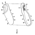
- the upper 14 is shown separated from the outsole 12.
- the upper 14 includes an outsole attachment area 60, a foot covering area 62, and a stabilizing member 64,
- the outsole attachment area 60 is provided along the upper 14 covering the length of attachment between the upper 14 and the outsole 12.
- the outsole attachment area 60 extends around the entire upper circumference 61. That is, the outsole attachment area 60 extends to provide attachment to the outsole 12 in the toe region 63, the arch region 65, and the heel region 67.
- the combination of the outsole attachment area 60 and the foot covering area 62 provided in the heel region 40 can be referred to as the heel wrap upper 66.
- the foot covering area 62 includes an opening 68 that allows for the insertion of a foot into the foot receiving area 18. Binding 69 can be provided along the foot covering area 62 to provide a finished appearance to the opening 68.
- the stabilizing member 64 is attached to the upper 14 along the outsole attachment area 60.
- One technique for attaching the stabilizing member 64 along the outsole attachment area 60 is by sewing to create a stitch line 70 and a seam allowance 72.
- the upper 14 can then be attached to the outsole 12 along the outsole retaining wall 74 to hide the stitch line 70 and the seam allowance 72.
- the upper 14 can be attached to the outsole 12 by stitching to create a stitch line 80 as shown in Figure 1 .
- the outsole 12 includes an outsole top side 82, an outsole bottom side 84, and an outsole retaining wall 74.
- the outsole retaining wall 74 extends above the outsole top side 82 along the perimeter 86. It should be understood that the outsole can be provided having various configurations and can be prepared by various manufacturing techniques without any preference for particular materials and processes expect to recognise that certain preferences may be based on various reasons including cost and customer preference.
- the upper 14 can be prepared from any fabric material commonly used in the manufacture of a slipper.
- the stabilizing member 64 can be provided from the same type of material used to provide the outsole attachment area 60. In general, the stabilizing member 64 is provided to assist with the attachment of the upper 14 to the outsole 12. The stabilizing member 64 helps the upper 14 maintain its shape during the step of attaching the upper 14 to the outsole 12.
- the upper can be attached to the outsole by stitching, it should be appreciated that other techniques can be used including adhesive bonding.
- the upper 14 is shown attached to the outsole 12 along the entire perimeter 86 in the embodiment shown in Figure 1 , alternatives can exist where the upper is not attached to the outsole in at least a portion of the perimeter.
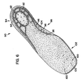
- the insole 90 includes a plurality of perforations or holes 92 provided in the heel region94, a plurality of perforations 96 provided in the arch region 98, and a plurality of perforations 100 provided in the toe region 102.
- the perforations provide for additional air circulation in order to make the slipper more comfortable for a wearer.
- the presence of the perforations 96 in the arch support 104 helps provide flexibility to the arch support 104. In general, slippers are available in whole sizes, and slippers are generally not available in half sizes. Accordingly, by providing a more flexible arch support 104, it is possible to provide the insole 90 with a larger degree of fit for various individuals.
- the insole according to the invention can be characterized as a removable, contoured footbed. That is, the insole is removable from the insole receiving area. It is expected that the insole may be glued in place within the insole receiving area to simply hold it in place until it is desired to remove the insole.
- the insole can be glued in place within the insole receiving area by spot gluing or placing spots of glue between the insole and the stabilizing member.
- the insole can be glued directly to the outsole.
- the insole can be referred to as a footbed because of the presence of the retaining wall and the arch support.
- the insole can be referred to as a contoured footbed because of the additional presence of the contour design. It is expected that the combination of the retaining wall and the arch support, when combined with the outsole retaining wall, will help stabilize a wearer's foot within the slipper,
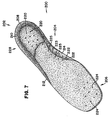
- the insole 200 includes a heel region 202, an arch region 204, and a toe region 206.
- a retaining wall 208 extends around the heel perimeter 210 and at least part way into the arch perimeter 212. It is pointed out that the arch support 214 forms a part of the retaining wall 208 that extends onto the arch perimeter 212.
- the insole 200 is shown having a plurality of perforations 220 in the heel region 202, a plurality of perforations 222 in the arch region 204, and a plurality of perforations 224 in the toe region 206.
- the plurality of perforations 222 include a plurality of perforations 223 in the arch support 214 and a plurality of perforations 225 in the arch region 204 that are not in the arch support 214.
- the perforations provide air flow and in the case of perforations 223, provide flexibility in the arch support 214.
- the heel cup region 228 of the insole 200 is shown without a contour design.
- the insole 200' includes a plurality of perforations 220' in the heel region 202', and does not include perforations in the arch region 204' and the toe region 206'.
- the heel region 202' includes a contour design 229' provided as a starburst pattern in the heel cup region 228'.
- the perforations 220' are shown within the central area of low density foam 231' of the starburst pattern 233' and not in the outlying areas of low density foam 235' of the starburst pattern 233'. It should be understood that, if desired, the perforations can be provided in either or both of the central area of low density foam 231' or the outlying areas of low density foam 235'.
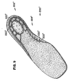
- the insole 200" includes perforations 200" in the heel region 202", and perforations 222" in the arch region 204".
- the insole 200"' includes no perforations and includes a contour design 229"' in the heel cup region 228"',
- Figures 11-16 are provided showing alternative slipper configurations that include representative examples of insole configurations. It should be understood that the various insole configurations according to the invention, such as those shown in Figures 3 and 6 , can be substituted for those insoles shown in Figures 11-16 .
- the slipper 300 includes an insole 302, an outsole 304, and an upper 306.
- the insole 302 can be provided as an insole or footbed according to the principles of the invention.
- the slipper 300 can be referred to as a closed back slipper because the upper 306 is constructed to include a heel wrap upper 308 that extends upward from the outsole 304 so that it wraps and encloses the wearer's heel.
- the upper 306 additionally includes a foot covering area 310 that covers the top of the wearer's foot.
- the upper 306 includes an opening through which the wearer's foot passes when taken on or off the slipper 300.
- the upper 306 can include elastic members 314 to help allow the wearer's foot to fit through the opening 312 by allowing a stretch between the foot top covering upper 316 and the side upper 318.
- the outsole 304 includes an outsole retaining wall 320 and the upper 306 is shown attached to the outsole retaining wall 320 along the outsole perimeter 322. As shown in Figure 12 , the outsole 304 can have an outsole retaining wall 320 having various configuration and styling as long as the upper is capable of attaching thereto.
- a slipper design according to the invention is shown as reference number 330.
- the slipper design 330 is similar to the slipper design 300 except that the outsole 332 includes cuts 334 that are visible when viewing the outsole exterior surface 336.
- the cuts can be provided in any desired design and can be provided to help increase flexibility and/or traction.
- the slippers 400 and 400' include an upper 402 and 402', and an outsole 404 and 404'.
- the upper 402 and 402' include a heel wrap portion 406 and 406' that is relatively low to the outsole. Because the heel wrap portion 406 and 406' is so low, the slippers 400 and 400' can be referred to as open back slippers. By providing open back slippers, it is generally easier to insert or remove a wearer's foot.
- the slippers 400 and 400' differ by the insoles 410 and 412 provided in the insole receiving areas 414 and 414'.
- the slipper design 450 includes an upper 452 and an outsole 454.
- the upper 452 includes a heel wrap portion 456 that can be considered sufficiently low so that the slipper 450 can be referred to as an open back slipper.
- the upper 452 includes an opening 458 above the location of the wearer's toes. Accordingly, the slipper 450 can be referred to as an open toe slipper.
- the upper 452 includes a toe wrap upper 460 that attaches to the outsole 454 in the toe area 462.
- the slipper 450 includes an insole 470 that is provided within the insole receiving area 472.
Abstract
Description
- The invention relates to a slipper insole, a slipper, and a method for manufacturing a slipper.
- The footwear industry is an old and crowded art. The industry is constantly attempting to design new products with aesthetic appeal, as well as being comfortable and having ease of construction.
- Various designs of slippers have been available for a number of years. See
U.S. Patent No. 5,392,532 (Bray, Jr. et al .) andU.S. Patent No. 6,226,894 (Bray, Jr. et al .). In general, slippers are a type of footwear having a generally soft construction and are generally washable in a conventional clothes washing machine. Slippers are typically not manufactured using a last, which is often a necessary device when manufacturing a shoe, including a hard sole and a leather upper. - Insoles for various shoes and slippers have been manufactured using compression molding of various polymers. See
U.S. Patent No. 5,551,173 (Chambers ),U.S. Patent No. 3,766 ,669 (Pearsall ),U.S. Patent No. 6,286,232 andU.S. Patent No. 4,513 518 . The insole provides a cushion and support for the foot. The comfort felt by the wearer of a shoe or slipper depends, in large part, on the ability of this foam insole to redistribute the various forces imposed on the foot during walking and standing. These forces are greatest in the heel, arch, and forefoot regions. - According to a first aspect the invention provides an insole for placing inside an insole receiving area of the slipper comprising:
- (a) a result of compression molding a structure comprising a foam layer having a first foam side and a second foam side, to provide an insole comprising:
- (i) a heel region having a heel cushioning portion and a heel perimeter portion, wherein the heel perimeter portion comprises a retaining wall that extends above the top surface of the heel cushioning portion;
- (ii) an arch region having an arch cushioning portion and an arch perimeter portion, wherein the arch perimeter portion comprises an arch support that extends above the top surface of the arch cushioning portion;
- (iii) a toe region having a toe cushioning portion and a toe perimeter portion; and
- (b) the heel cushioning portion comprises a contour design including a first higher density foam area and a first central lower density foam area that is surrounded by the first higher density foam area, wherein the first central lower density foam area is surrounded by a plurality of isolated lower density foam areas, and the plurality of isolated lower density foam areas are separated from each other by portions of the first higher density foam area.
- According to a second aspect of the invention we provide a slipper comprising:
- (a) an outsole having a top outsole side, a bottom outsole side, and an outsole retaining wall extending along a circumference of the outsole;
- (b) an upper having an outsole attachment area and a foot covering area, wherein:
- (i) the outsole attachment area is attached to the outsole retaining wall to provide an insole receiving area between the foot covering area and the outsole;
- (c) an insole placed within the insole receiving area, the insole comprising a result of molding a structure comprising a foam layer having a first foam side and a second foam side, to provide an insole comprising:
- (i) a heel region having a heel cushioning portion and a heel perimeter portion, wherein the heel perimeter portion comprises a retaining wall that extends above the top surface of the heel cushioning portion;
- (ii) an arch region having an arch cushioning portion and an arch perimeter portion, wherein the arch perimeter portion comprises an arch support that extends above the top surface of the arch cushioning portion;
- (iii) a toe region having a toe cushioning portion and a toe perimeter portion; and characterised in that;
- (iv) the heel cushioning portion comprises a contour design including a first higher density foam area and a first central lower density foam area that is surrounded by the first higher density foam area, wherein the first central lower density foam area is surrounded by a plurality of isolated lower density foam areas, and the plurality of isolated lower density foam areas are separated from each other by portions of the first higher density foam area.
-
-
Figure 1 is a perspective view of a slipper construction according to the principles of the invention wherein the contoured footbed has been removed. -
Figure 2 is a perspective, assembly view of an insole according to the principles of the invention prior to compression molding. -
Figure 3 is a perspective view of an insole according to the principles of the invention. -
Figure 4 is a bottom view of the insole ofFigure 3 . -
Figure 5 is a perspective, assembly view of the slipper construction ofFigure 1 . -
Figure 6 is a perspective view of an alternative embodiment of an insole according to the principles of the invention. -
Figures 7-10 are perspective view of alternative embodiments of insoles according to the principles of the invention. -
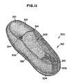
Figures 11 is a perspective view of a closed back slipper according to the principles of the invention. -
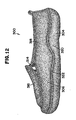
Figure 12 is a side view of the closed back slipper ofFigure 11 . -
Figure 13 is a side view of an alternative closed back slipper according to the principles of the invention. -
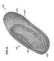
Figure 14 is a perspective view of an open back according to the principles of the invention. -
Figure 15 is a perspective view of an open back slipper according to the principles of the invention. -
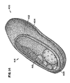
Figure 16 is a perspective view of an open toe slipper according to the principles of the invention. - Referring to
Figures 1-5 , a slipper according to the present invention is shown atreference numeral 10. Theslipper 10 includes anoutsole 12, an upper 14, and aninsole 16. Theinsole 16 is removable from theinsole receiving area 18 and is shown removed inFigures 1 and5 . Theslipper 10 can be characterized as having a generally soft construction while providing support for a wearer's foot. - The
insole 16 has atop surface 20 and abottom surface 24. As shown inFigure 3 , thetop surface 20 includes acontour design 22 in aheel cup region 23. When theinsole 16 is provided within theinsole receiving area 18, thecontour design 22 is readily visible to someone looking at theslipper 10. It is believed that thecontour design 22 provides visual interest for a customer of the slipper and may cause the customer to examine theslipper 10 more closely. It is believed that customers will associate thecontour design 22 with slippers having an insole according to the invention. In addition, thecontour design 22 is believed to provide additional cushioning. - The
insole 16 can be assembled by laminating afirst layer 26 and asecond layer 28 to provide alaminate construction 30, and compression molding thelaminate construction 30. Thefirst layer 26 can be afoam layer 27, and thesecond layer 28 can be afabric layer 29. Thefoam layer 27 includes afirst foam side 31 and asecond foam side 32. Thefabric layer 29 includes afirst fabric side 33 and asecond fabric side 34. Thefabric layer 29 is placed over thefoam layer 27 so that thesecond fabric side 34 is adjacent to thefirst foam side 31. Thefabric layer 29 can be held in place on thefoam layer 27 by an adhesive. Adhesive can be applied as a dry powder adhesive, a hot melt adhesive, a water based adhesive, etc. to hold thefabric layer 29 in place on thefoam layer 27. It is expected that the compression molding step will cause a portion of thefoam layer 27 to melt thereby creating a bond between thefabric layer 29 and thefoam layer 27. It should be understood that compression molding is a generally well known technique for molding to create a molded article. To the extent molding techniques other than compression molding can be used to prepare the insole according to the invention, those techniques can generally be referred to as "molding." - The
foam layer 27 can be prepared from any foam material that exhibits the desired level of support and resiliency that is appropriate for use as an insole. It should be understood that the characterization of the desired level of support and resiliency refers to properties after molding to provide the insole. An exemplary foam material that can be used includes ethylene vinyl acetate. A particular form of ethylene vinyl acetate that can be used is sponge ethylene vinyl acetate. The density of the foam layer should be sufficient to provide the desired level of support after the foam has been compression molded. If the foam density is too low, it is expected that insufficient support will be provided. If the foam density is too high, it is expected that the foam will be too rigid. A desirable foam density range can be between about 19.5kg/m2 (about 41b/ft2) and about 48.8kg/m2 (about 100b/ft2) prior to compression molding. In general, it is difficult to measure the density of thefoam layer 27 after compression molding because different parts of theinsole 16 can be compressed to different levels and thereby provide different densities. - It is pointed out that the
foam layer 27 shown inFigure 2 is not necessarily drawn to scale. It is expected that a relativelythick foam layer 27 will be compressed to provide theinsole 16. For example, the foam layer can be provided as 7.62cm (3 inch) block that is molded to provide a desired final thickness. In addition, the foam layer can be provided as multiple layers of foam materials that may be the same or different. - The
fabric layer 29 can be provided from any type of fabric material that adheres to thefoam layer 27 and provides a desired surface texture. The fabric layer can be a woven material, a nonwoven material, or a knitted material. Because it is desirable for thecontour design 22 to be visible, it is generally desirable for thefabric layer 29 to have a nap that is sufficiently small (if it exists at all) so it does not obscure thecontour design 22. In general, it is expected that the nap will be less than about 4 mm. An exemplary fabric material that can be used includes microfiber sueded fabric. An exemplary microfiber sueded fabric includes a fabric prepared from polyester. - It should be understood that the insole according to the invention can be provided without the
fabric layer 29. If there is nofabric layer 29, the wearer's foot can directly contact thefoam layer 27. it is expected that the fabric layer, when present, can be selected to provide a desired feel against the wearer's foot. - The
insole 16 additionally includes a retainingwall 36 and anarch support 38. Thecontour design 22, the retainingwall 36, and thearch support 38 can be formed during the compression molding step. The retainingwall 36 extends along a portion of theinsole perimeter 39. Thearch support 38 extends along a portion of the insole perimeter in the region where arch support is desired. - The
insole 16 includes three general regions. These regions include aheel region 40, anarch region 42, and atoe region 44. In general, theheel region 40 includes that portion of theinsole 16 that generally contains and supports the wearer's heel. Thetoe region 44 includes that portion of theinsole 16 that generally contains and supports the wearer's toes. Thearch region 42 is generally that portion of theinsole 16 provided between theheel region 40 and thetoe region 44 and provides support for the wearer's arch. It should be understood that there can be some degree of overlap between the regions. Theheel region 40 includes aheel cushioning area 46 and aheel perimeter 47, thearch region 42 includes anarch cushioning area 48 and anarch perimeter 49, and thetoe region 44 includes atoe cushioning area 50 and atoe perimeter 51. It should be understood that thecushioning areas insole 16 that cushions the corresponding part of a wearer's foot, and theperimeters insole perimeter 39 of theinsole 16. - As shown in
Figure 3 , the retainingwall 36 extends around theheel perimeter 47 and into thearch perimeter 49. For the design shown inFigure 3 , the retainingwall 36 does not extend into thetoe perimeter 51, The retainingwall 36 is constructed so that it extends above the heel cushioning areatop surface 52 and the arch cushioning areatop surface 54 to an extent sufficient to help retain the wearer's foot in its proper location on theinsole 16. The retainingwall 36 can have a varying height depending upon whether it is located in theheel region 40 or thearch region 42. The retainingwall 36 can have a height that is sufficient for providing containment and/or support of the wearer's foot, but should not be so high that it causes discomfort. An exemplary range for the retainingwall 36 can be between about 0,64cm (about 1/4 inch) and about 2.54cm (about 1 inch). In many applications, it is expected that the retainingwall 36 will have a height of about 2.22cm (about 7/8 inch) above the heel cushioning areatop surface 52 and the arch cushioningtop surface 54. Because it is expected that thetoe region 44 will be compressed more than theheel region 40 and thearch region 42, it is expected that the toe cushioning areatop surface 56 will be lower than the heel cushioning areatop surface 52 and the arch cushioning areatop surface 54. In addition, it should be understood that the retainingwall 36 can decrease until it merges with the arch cushioning areatop surface 54 and/or the toe cushioning areatop surface 56. - The combination of the
heel cushioning area 46 and the retainingwall 36 provided in theheel perimeter 47 provides a structure that can be referred to as theheel cup region 23 because it acts to contain the wearer's heel and keep it in a stationary position. Theheel cushioning area 46 includes thecontour design 22. In addition to providing visual interest to a customer, it is believed that thecontour design 22 provides additional cushioning. Thecontour design 22 includes areas of relativelylower density foam 57 and areas of relativelyhigher density foam 58. Thecontour design 22 shown inFigure 3 can be referred to as astarburst pattern 41 because it includes a relatively low densitycentral area 59 surrounded by isolated domains of relatively low density from 55. It should be understood that the reference to low density foam refers to the comparison with the adjacent areas of relativelyhigher density foam 58. The difference in height between the lowerdensity foam areas 57 and the higherdensity foam areas 58 should be sufficient to be readily visible upon inspection of theinsole 16, but should not be so large as to cause discomfort. In general, it is expected that the difference in height between thelow density area 57 and thehigher density areas 58 will be between about 0.16cm and about 0.48cm (about 1/16 inch and about 3/16 inch). It should be understood that the contour design may or may not be present in theheel cup region 23, and may include various designs such as those of interest to customers. - Now referring to
Figure 5 , the upper 14 is shown separated from theoutsole 12. The upper 14 includes anoutsole attachment area 60, a foot covering area 62, and a stabilizingmember 64, Theoutsole attachment area 60 is provided along the upper 14 covering the length of attachment between the upper 14 and theoutsole 12. For the construction of the upper 14 shown inFigure 5 , theoutsole attachment area 60 extends around the entireupper circumference 61. That is, theoutsole attachment area 60 extends to provide attachment to theoutsole 12 in thetoe region 63, thearch region 65, and theheel region 67. The combination of theoutsole attachment area 60 and the foot covering area 62 provided in theheel region 40 can be referred to as the heel wrap upper 66. The foot covering area 62 includes anopening 68 that allows for the insertion of a foot into thefoot receiving area 18. Binding 69 can be provided along the foot covering area 62 to provide a finished appearance to theopening 68. - The stabilizing
member 64 is attached to the upper 14 along theoutsole attachment area 60. One technique for attaching the stabilizingmember 64 along theoutsole attachment area 60 is by sewing to create astitch line 70 and aseam allowance 72. The upper 14 can then be attached to theoutsole 12 along theoutsole retaining wall 74 to hide thestitch line 70 and theseam allowance 72. The upper 14 can be attached to theoutsole 12 by stitching to create astitch line 80 as shown inFigure 1 . - The
outsole 12 includes an outsoletop side 82, anoutsole bottom side 84, and anoutsole retaining wall 74. Theoutsole retaining wall 74 extends above the outsoletop side 82 along theperimeter 86. It should be understood that the outsole can be provided having various configurations and can be prepared by various manufacturing techniques without any preference for particular materials and processes expect to recognise that certain preferences may be based on various reasons including cost and customer preference. - The upper 14 can be prepared from any fabric material commonly used in the manufacture of a slipper. The stabilizing
member 64 can be provided from the same type of material used to provide theoutsole attachment area 60. In general, the stabilizingmember 64 is provided to assist with the attachment of the upper 14 to theoutsole 12. The stabilizingmember 64 helps the upper 14 maintain its shape during the step of attaching the upper 14 to theoutsole 12. Although the upper can be attached to the outsole by stitching, it should be appreciated that other techniques can be used including adhesive bonding. Although the upper 14 is shown attached to theoutsole 12 along theentire perimeter 86 in the embodiment shown inFigure 1 , alternatives can exist where the upper is not attached to the outsole in at least a portion of the perimeter. - Now referring to
Figure 6 , an alternative design of an insole according to the principles of the invention is shown atreference numeral 90. Theinsole 90 includes a plurality of perforations or holes 92 provided in the heel region94, a plurality ofperforations 96 provided in thearch region 98, and a plurality ofperforations 100 provided in thetoe region 102. The perforations provide for additional air circulation in order to make the slipper more comfortable for a wearer. In addition, the presence of theperforations 96 in the arch support 104 helps provide flexibility to the arch support 104. In general, slippers are available in whole sizes, and slippers are generally not available in half sizes. Accordingly, by providing a more flexible arch support 104, it is possible to provide theinsole 90 with a larger degree of fit for various individuals. - The insole according to the invention can be characterized as a removable, contoured footbed. That is, the insole is removable from the insole receiving area. It is expected that the insole may be glued in place within the insole receiving area to simply hold it in place until it is desired to remove the insole. The insole can be glued in place within the insole receiving area by spot gluing or placing spots of glue between the insole and the stabilizing member. In addition, if the upper is attached to the outsole without a stabilizing member, the insole can be glued directly to the outsole. The insole can be referred to as a footbed because of the presence of the retaining wall and the arch support. The insole can be referred to as a contoured footbed because of the additional presence of the contour design. It is expected that the combination of the retaining wall and the arch support, when combined with the outsole retaining wall, will help stabilize a wearer's foot within the slipper,
- Now referring to
Figures 7-10 , alternative insoles according to the present invention are shown. - Now referring to
Figure 7 , theinsole 200 includes aheel region 202, anarch region 204, and atoe region 206. A retainingwall 208 extends around theheel perimeter 210 and at least part way into thearch perimeter 212. It is pointed out that thearch support 214 forms a part of theretaining wall 208 that extends onto thearch perimeter 212. These features of the insole 200 (Figure 7 ) area similarly found in the insole 200' (Figure 8 ), theinsole 200" (Figure 9 ), and theinsole 200"' (Figure 10 ). - The
insole 200 is shown having a plurality ofperforations 220 in theheel region 202, a plurality ofperforations 222 in thearch region 204, and a plurality ofperforations 224 in thetoe region 206. The plurality ofperforations 222 include a plurality ofperforations 223 in thearch support 214 and a plurality ofperforations 225 in thearch region 204 that are not in thearch support 214. In general, the perforations provide air flow and in the case ofperforations 223, provide flexibility in thearch support 214. Theheel cup region 228 of theinsole 200 is shown without a contour design. - The insole 200' includes a plurality of perforations 220' in the heel region 202', and does not include perforations in the arch region 204' and the toe region 206'. In addition, the heel region 202' includes a contour design 229' provided as a starburst pattern in the heel cup region 228'. The perforations 220' are shown within the central area of low density foam 231' of the
starburst pattern 233' and not in the outlying areas of low density foam 235' of thestarburst pattern 233'. It should be understood that, if desired, the perforations can be provided in either or both of the central area of low density foam 231' or the outlying areas of low density foam 235'. Theinsole 200" includesperforations 200" in theheel region 202", andperforations 222" in thearch region 204". Theinsole 200"' includes no perforations and includes acontour design 229"' in theheel cup region 228"', - It should be understood that the various insole configurations according to the invention can be placed in the insole receiving area of various slipper configurations.
Figures 11-16 are provided showing alternative slipper configurations that include representative examples of insole configurations. It should be understood that the various insole configurations according to the invention, such as those shown inFigures 3 and6 , can be substituted for those insoles shown inFigures 11-16 . - Now referring to
Figure 11 , an alternative slipper design according to the invention is shown atreference number 300. Theslipper 300 includes aninsole 302, anoutsole 304, and an upper 306. Theinsole 302 can be provided as an insole or footbed according to the principles of the invention. Theslipper 300 can be referred to as a closed back slipper because the upper 306 is constructed to include a heel wrap upper 308 that extends upward from theoutsole 304 so that it wraps and encloses the wearer's heel. The upper 306 additionally includes afoot covering area 310 that covers the top of the wearer's foot. The upper 306 includes an opening through which the wearer's foot passes when taken on or off theslipper 300. The upper 306 can includeelastic members 314 to help allow the wearer's foot to fit through theopening 312 by allowing a stretch between the foot top covering upper 316 and the side upper 318. Theoutsole 304 includes anoutsole retaining wall 320 and the upper 306 is shown attached to theoutsole retaining wall 320 along theoutsole perimeter 322. As shown inFigure 12 , theoutsole 304 can have anoutsole retaining wall 320 having various configuration and styling as long as the upper is capable of attaching thereto. - Now referring to
Figure 13 , a slipper design according to the invention is shown asreference number 330. Theslipper design 330 is similar to theslipper design 300 except that theoutsole 332 includescuts 334 that are visible when viewing theoutsole exterior surface 336. The cuts can be provided in any desired design and can be provided to help increase flexibility and/or traction. - Now referring to
Figures 14 and16 , alternative slipper designs according to the invention area shown atreference number 400 and 400'. Theslippers 400 and 400' include an upper 402 and 402', and anoutsole 404 and 404'. The upper 402 and 402' include aheel wrap portion 406 and 406' that is relatively low to the outsole. Because theheel wrap portion 406 and 406' is so low, theslippers 400 and 400' can be referred to as open back slippers. By providing open back slippers, it is generally easier to insert or remove a wearer's foot. - The
slippers 400 and 400' differ by theinsoles insole receiving areas 414 and 414'. - Now referring to
Figure 16 , an alternative slipper design is shown atreference number 450. Theslipper design 450 includes an upper 452 and anoutsole 454. The upper 452 includes aheel wrap portion 456 that can be considered sufficiently low so that theslipper 450 can be referred to as an open back slipper. In addition, the upper 452 includes anopening 458 above the location of the wearer's toes. Accordingly, theslipper 450 can be referred to as an open toe slipper. In the case of theslipper 450, the upper 452 includes a toe wrap upper 460 that attaches to theoutsole 454 in thetoe area 462. Theslipper 450 includes aninsole 470 that is provided within theinsole receiving area 472.
Claims (23)
- An insole (16) for placing inside an insole receiving area (18) of a slipper (10) comprising:(a) a result of compression molding a structure comprising a foam layer (27) having a first foam side (31) and a second foam side (32), to provide an insole comprising:(i) a heel region (40) having a heel cushioning portion (46) and a heel perimeter portion (47), wherein the heel perimeter portion comprises a retaining wall (36) that extends above the top surface of the heel cushioning portion;(ii) an arch region (42) having an arch cushioning portion (48) and an arch perimeter portion (49), wherein the arch perimeter portion comprises an arch support (38, 104) that extends above the top surface of the arch cushioning portion;(iii) a toe region (44) having a toe cushioning portion (50) and a toe perimeter portion (51); and characterised in that;(b) the heel cushioning portion comprises a contour design (22) including a first higher density foam area (58) and a first central lower density foam area (59) that is surrounded by the first higher density foam area, wherein the first central lower density foam area is surrounded by a plurality of isolated lower density foam areas (55), and the plurality of isolated lower density foam areas are separated from each other by portions of the first higher density foam area.
- An insole (16) according to claim 1, wherein the toe perimeter portion does not include a retaining wall (36).
- An insole (16) according to claim 1, wherein the contour design comprises a starburst pattern (41).
- An insole (16) according to claim 1, where the foam layer comprises ethylene vinyl acetate.
- An insole (16) according to claim 1, wherein the structure comprises a laminate of the foam layer and a fabric layer (29) having a first fabric side (33) and a second fabric side (34), wherein the second fabric side is attached to the first foam side.
- An insole (16) according to claim 5, wherein the fabric layer has a nap of less than 4mm.
- An insole (16) according to claim 1, wherein the arch perimeter portion comprises a retaining wall (36) that extends above the top surface of the heel cushioning portion.
- An insole (16) according to claim 1, wherein the retaining wall of the heel perimeter portion extends 6.35mm (¼ inch) to 25.4mm (1 inch) above the top surface of the heel cushioning portion.
- An insole (16) according to claim 1, wherein the arch support extends 6.35mm (¼ inch) to 25.4mm (1 inch) above the top surface of the arch cushioning portion.
- An insole (16) according to claim 1, wherein the arch support comprises a plurality of perforations (96) for increasing the flexibility of the arch support.
- An insole (16) according to claim 1, wherein at least one of the heel region, the arch region, and the toe region comprises a plurality of perforations (92, 96, 100) for increasing air circulation.
- A slipper (10) comprising:(a) an outsole (12) having a top outsole side (82), a bottom outsole side (84), and an outsole retaining wall (74) extending along a circumference of the outsole;(b) an upper (14) having an outsole attachment area (60) and a foot covering area (62), wherein:(i) the outsole attachment area is attached to the outsole retaining wall to provide an insole receiving area (18) between the foot covering area and the outsole;and(c) an insole (16) placed within the insole receiving area, the insole comprising a result of compression molding a structure comprising a foam layer (27) having a first foam side (31) and a second foam side (32), to provide an insole comprising:(i) a heel region (40) having a heel cushioning portion (46) and a heel perimeter portion (47), wherein the heel perimeter portion comprises a retaining wall (36) that extends above the top surface of the heel cushioning portion;(ii) an arch region (42) having an arch cushioning portion (48) and an arch perimeter portion (49), wherein the arch perimeter portion comprises an arch support (38, 104) that extends above the top surface of the arch cushioning portion;(iii) a toe region (44) having a toe cushioning portion (50) and a toe perimeter portion (51); and characterised in that;(iv) the heel cushioning portion comprises a contour design (22) including a first higher density foam area (58) and a first central lower density foam area (59) that is surrounded by the first higher density foam area, wherein the first central lower density foam area is surrounded by a plurality of isolated lower density foam areas (55), and the plurality of isolated lower density foam areas are separated from each other by portions of the first higher density foam area.
- A slipper (10) according to claim 12, wherein the upper further comprises a stabilizing member (64) attached along the outsole attachment area.
- A slipper (10) according to claim 12, wherein the toe perimeter portion does not include a retaining wall (36).
- A slipper (10) according to claim 12, where in the contour design comprises a starburst pattern (41).
- A slipper (10) according to claim 12, wherein the foam layer comprises ethylene vinyl acetate.
- A slipper (10) according to claim 12, wherein the structure comprises a laminate of the foam layer and a fabric layer (29) having a first fabric side (33) and a second fabric side (34), wherein the second fabric side is attached to the first foam side.
- A slipper (10) according to claim 18, wherein the fabric layer has a nap of less than 4mm.
- A slipper (10) according to claim 12, wherein the arch perimeter portion comprises a retaining wall (36) that extends above the top surface of the heel cushioning portion.
- A slipper (10) according to claim 12, wherein the retaining wall of the heel perimeter portion extends about 6.35mm (¼ inch) to 25.4mm (1 inch) above the top surface of the heel cushioning portion.
- A slipper (10) according to claim 12, wherein the arch support extends 6.35mm (¼ inch) to 25.4mm (1 inch) above the top surface of the arch cushioning portion.
- A slipper (10) according to claim 12, wherein the arch support comprises a plurality of perforations (96) for increasing the flexibility of the arch support.
- A slipper (10) according to claim 12, wherein at least one of the heel region, the arch region, and the toe region comprises a plurality of perforations (92, 96, 100) for increasing air circulation.
Applications Claiming Priority (3)
| Application Number | Priority Date | Filing Date | Title |
|---|---|---|---|
| US10/213,276 US6990754B2 (en) | 2002-08-05 | 2002-08-05 | Slipper insole, slipper, and method for manufacturing a slipper |
| US213276 | 2002-08-05 | ||
| PCT/US2003/024409 WO2004012545A1 (en) | 2002-08-05 | 2003-08-05 | Slipper insert, slipper, and method for manufacturing a slipper |
Publications (2)
| Publication Number | Publication Date |
|---|---|
| EP1526786A1 EP1526786A1 (en) | 2005-05-04 |
| EP1526786B1 true EP1526786B1 (en) | 2009-02-18 |
Family
ID=31187866
Family Applications (1)
| Application Number | Title | Priority Date | Filing Date |
|---|---|---|---|
| EP03767179A Expired - Lifetime EP1526786B1 (en) | 2002-08-05 | 2003-08-05 | Slipper insert, slipper, and method for manufacturing a slipper |
Country Status (7)
| Country | Link |
|---|---|
| US (3) | US6990754B2 (en) |
| EP (1) | EP1526786B1 (en) |
| AT (1) | ATE422830T1 (en) |
| AU (1) | AU2003263984A1 (en) |
| CA (1) | CA2493762A1 (en) |
| DE (1) | DE60326239D1 (en) |
| WO (1) | WO2004012545A1 (en) |
Families Citing this family (32)
| Publication number | Priority date | Publication date | Assignee | Title |
|---|---|---|---|---|
| DE10220004A1 (en) * | 2002-05-03 | 2003-11-20 | Elefanten Gmbh | footbed |
| US6990754B2 (en) | 2002-08-05 | 2006-01-31 | R. G. Barry Corporation | Slipper insole, slipper, and method for manufacturing a slipper |
| US7503130B2 (en) * | 2003-12-04 | 2009-03-17 | Genesco, Inc. | Water draining shoe |
| US20060179684A1 (en) * | 2005-02-16 | 2006-08-17 | E&E Hosiery, Inc. | Outer sole |
| US20070033835A1 (en) * | 2005-08-02 | 2007-02-15 | Bray Walter T Jr | Insole arrangement; footwear with insole arrangement; and, method of preparation |
| US7958653B2 (en) * | 2006-09-21 | 2011-06-14 | Schering-Plough Healthcare Products, Inc. | Cushioned orthotic |
| US7845095B2 (en) * | 2007-03-06 | 2010-12-07 | Nike, Inc. | Article of footwear for use with a left foot and a right foot |
| TW200920278A (en) * | 2007-11-13 | 2009-05-16 | zhong-ren Lin | Improved pad structure of breathing insole |
| CN101513288B (en) * | 2008-02-22 | 2010-10-13 | 林重仁 | Pad body improvement structure for ventilation shoe pad |
| GB2458282A (en) * | 2008-03-12 | 2009-09-16 | Foot Rite Ltd | An orthotic device |
| ES2351245B1 (en) * | 2008-05-28 | 2011-12-13 | Certino Mode, Sl | PLANT FOR FOOTWEAR AND FOOTWEAR THAT INCLUDES SUCH PLANT |
| WO2010077296A2 (en) * | 2008-12-09 | 2010-07-08 | Red Wing Shoe Company, Inc. | Molded insole for welted footwear |
| WO2010104824A1 (en) * | 2009-03-09 | 2010-09-16 | Aetrex Worldwide, Inc. | Shoe sole inserts for pressure distribution |
| US9167867B2 (en) * | 2010-05-13 | 2015-10-27 | Nike, Inc. | Article of footwear with multi-part sole assembly |
| US20130031809A1 (en) * | 2011-08-05 | 2013-02-07 | Roses & Rye LLC | Shoe having improved podiatric support |
| JP5120743B1 (en) * | 2012-05-28 | 2013-01-16 | 恵里 田邊 | Jumping shoes and method of manufacturing jumping shoes |
| US20150196090A1 (en) * | 2014-01-10 | 2015-07-16 | Jesse James Sluder, SR. | Cast Sole Insert |
| JP5858450B1 (en) * | 2015-02-12 | 2016-02-10 | 山本 秀二 | Insoles |
| USD774736S1 (en) * | 2015-02-25 | 2016-12-27 | Deckers Outdoor Corporation | Footwear upper |
| CN107920677A (en) * | 2015-06-26 | 2018-04-17 | 现代包装有限责任公司 | Overmolded low cost tableware |
| CN108289637B (en) | 2015-10-05 | 2021-07-02 | 斯格尔兹威尔尼斯公司 | Generating orthotic product recommendations |
| US10856610B2 (en) | 2016-01-15 | 2020-12-08 | Hoe-Phuan Ng | Manual and dynamic shoe comfortness adjustment methods |
| USD826526S1 (en) * | 2017-05-15 | 2018-08-28 | Nike, Inc. | Shoe outsole |
| USD873550S1 (en) | 2017-05-16 | 2020-01-28 | Nike, Inc. | Shoe |
| USD898335S1 (en) | 2017-05-16 | 2020-10-13 | Nike, Inc. | Shoe |
| USD897090S1 (en) | 2017-05-16 | 2020-09-29 | Nike, Inc. | Shoe |
| MX2020004040A (en) | 2017-10-13 | 2020-08-13 | Scholl´S Wellness Company Llc | Footcare product dispensing kiosk. |
| USD860598S1 (en) | 2018-02-28 | 2019-09-24 | Nike, Inc. | Shoe |
| USD880123S1 (en) | 2018-08-03 | 2020-04-07 | Nike, Inc. | Shoe |
| USD974715S1 (en) * | 2022-09-07 | 2023-01-10 | Jiangfu Lin | Shoe |
| USD975410S1 (en) * | 2022-09-08 | 2023-01-17 | Jiangfu Lin | Shoe |
| USD1004919S1 (en) * | 2023-06-29 | 2023-11-21 | Quanzhou Fengling Trading Co., Ltd. | Shoe |
Citations (1)
| Publication number | Priority date | Publication date | Assignee | Title |
|---|---|---|---|---|
| EP0971606B1 (en) * | 1997-05-14 | 2001-10-31 | Hans Seiter | Inner sole for a shoe |
Family Cites Families (64)
| Publication number | Priority date | Publication date | Assignee | Title |
|---|---|---|---|---|
| USRE18237E (en) | 1927-10-29 | 1931-10-27 | Island | |
| US2715285A (en) | 1952-02-19 | 1955-08-16 | Vecchio Angelo Del | Laminated sole structure |
| US3468040A (en) * | 1967-12-13 | 1969-09-23 | Tatuo Fukuoka | Sandals |
| US3766669A (en) * | 1969-08-21 | 1973-10-23 | Usm Corp | Profiled cellular article |
| JPS5429946Y2 (en) | 1975-05-01 | 1979-09-21 | ||
| JPS5411065Y2 (en) * | 1975-08-11 | 1979-05-19 | ||
| US4020570A (en) * | 1975-10-10 | 1977-05-03 | Hiraoka New York, Inc. | Cushioned insole for footwear such as shoes, boots, or the like |
| DE2607380C3 (en) * | 1976-02-24 | 1981-07-23 | Bayer Ag, 5090 Leverkusen | Process for the production of thermoformable polyisocyanurate foams |
| GB1571127A (en) * | 1976-04-02 | 1980-07-09 | Scholl Uk Ltd | Soles for footwear and footwear incorporating them |
| USD276003S (en) * | 1982-05-24 | 1984-10-23 | Mcabery Robert | Slipper |
| US4513518A (en) * | 1982-09-30 | 1985-04-30 | Rogers Foam Corporation | Shoe inner sole |
| US4674204A (en) * | 1983-02-28 | 1987-06-23 | Sullivan James B | Shock absorbing innersole and method for preparing same |
| US4910886B1 (en) * | 1983-02-28 | 1995-05-09 | Atlantic Thermoplastics Co Inc | Shock-absorbing innersole |
| DE3309127A1 (en) * | 1983-03-15 | 1984-09-20 | Basf Ag, 6700 Ludwigshafen | CELLED POLYURETHANE MOLDED BODIES, METHOD FOR THE PRODUCTION THEREOF BY THERMOPLASTIC DEFORMING OF POLYESTER-POLYURETHANE FOAMS AND THE USE THEREOF |
| US4551930A (en) * | 1983-09-23 | 1985-11-12 | New Balance Athletic Shoe, Inc. | Sole construction for footwear |
| USD284901S (en) | 1984-05-17 | 1986-08-05 | Tilles Harvey G | Insole for shoes used in lateral sports |
| US4627177A (en) * | 1984-07-02 | 1986-12-09 | Meyers Stuart R | Insole structure |
| US4633877A (en) * | 1984-08-07 | 1987-01-06 | Duramet Systems, Inc. | Dynamic foot support and kit therefor |
| US4760655A (en) * | 1986-07-07 | 1988-08-02 | Walter Mauch | Insole |
| USD294537S (en) * | 1986-12-08 | 1988-03-08 | Reebok International Ltd. | Shoe sole |
| US4864740A (en) * | 1986-12-22 | 1989-09-12 | Kimberly-Clark Corporation | Disposable hygienic shoe insole and method for making the same |
| US4741951A (en) * | 1987-01-29 | 1988-05-03 | Reeves Bros., Inc. | Method for forming thermoformable polyurethane foam articles |
| US5015427A (en) | 1987-08-04 | 1991-05-14 | Happi, Inc. | Process for making an orthotic footwear insert |
| US4956927A (en) * | 1988-12-20 | 1990-09-18 | Colgate-Palmolive Company | Monolithic outsole |
| US4955148A (en) * | 1989-04-14 | 1990-09-11 | Rigoberto Padilla | Foot support assembly |
| US5146698A (en) * | 1989-05-08 | 1992-09-15 | Tilles Harvey G | Shoe insole proform II |
| US5154682A (en) * | 1989-09-14 | 1992-10-13 | David Kellerman | Low friction adjustable shoe insert |
| US5203793A (en) | 1989-09-20 | 1993-04-20 | Lyden Robert M | Conformable cushioning and stability device for articles of footwear |
| US5167999A (en) * | 1991-06-18 | 1992-12-01 | Wang Sui Mu | Liquid cushioning means |
| DE4206818A1 (en) * | 1992-03-04 | 1992-07-02 | Prodomo Sa | INSOLE |
| USD354389S (en) | 1993-05-05 | 1995-01-17 | Schering-Plough Healthcare Products, Inc. | Sports insole with perforations |
| USD354844S (en) * | 1993-09-30 | 1995-01-31 | Dixie Rinehart | Shoe |
| US5392532A (en) * | 1993-10-18 | 1995-02-28 | R. G. Barry Corporation | Slipper having an insole attached to a peripheral outsole wall |
| JP2573508Y2 (en) * | 1993-12-28 | 1998-06-04 | 美津濃株式会社 | Cup insole |
| US5483757A (en) | 1994-02-03 | 1996-01-16 | Frykberg; Robert G. | Healing sandal |
| US5718064A (en) * | 1994-04-04 | 1998-02-17 | Nine West Group Inc. | Multi-layer sole construction for walking shoes |
| EP0755203A4 (en) * | 1994-04-15 | 1998-05-06 | Donna Karan Shoe Company | Insole |
| US5435077A (en) * | 1994-04-18 | 1995-07-25 | The United States Shoe Corporation | Layered cushioning system for shoe soles |
| US5611153A (en) * | 1994-05-12 | 1997-03-18 | Schering-Plough Healthcare Products, Inc. | Insole for heel pain relief |
| USD366140S (en) | 1994-06-29 | 1996-01-16 | Amasia International, Ltd. | Shoe sock lining |
| USD366956S (en) | 1994-12-21 | 1996-02-13 | Schering-Plough Healthcare Products, Inc. | Work boot insole |
| US5551173A (en) * | 1995-03-16 | 1996-09-03 | Chambers; Mark D. | Comfort insole |
| US5675914A (en) | 1995-11-13 | 1997-10-14 | The Rockport Company, Inc. | Air circulating footbed |
| US5669162A (en) * | 1996-03-07 | 1997-09-23 | Brown Group, Inc. | Cushion insert |
| USD399042S (en) | 1996-06-04 | 1998-10-06 | Sara Lee Corporation | Shoe insole |
| US5787608A (en) * | 1996-07-30 | 1998-08-04 | Greenawalt; Kent S. | Custom-made footwear |
| USD426373S (en) | 1997-05-21 | 2000-06-13 | Acushnet Company | Foot-bed |
| US6226894B1 (en) * | 1998-05-11 | 2001-05-08 | R. G. Barry Corporation | Slipper and method for manufacturing slipper |
| USD418281S (en) * | 1998-05-11 | 2000-01-04 | R. G. Barry Corporation | Open toe slipper |
| US6205684B1 (en) * | 1998-11-13 | 2001-03-27 | Zephyr Athletic Footwear, Inc. | Strike pad assembly |
| US6176025B1 (en) * | 1999-05-28 | 2001-01-23 | Spalding Sports Worldwide, Inc. | Cushioning system for golf shoes |
| USD432769S (en) | 1999-07-26 | 2000-10-31 | Wu-Bin Yung | Insole |
| US6219941B1 (en) * | 1999-09-14 | 2001-04-24 | Jay J. Kukoff | Foot massaging shoe insole and method of making same |
| USD423766S (en) | 1999-10-07 | 2000-05-02 | Sherry Genga | High heel inset |
| US6418642B1 (en) | 2000-01-11 | 2002-07-16 | R. G. Barry Corporation | Slipper with polymer insole jell and method for manufacturing |
| US6286232B1 (en) * | 2000-01-28 | 2001-09-11 | Schering-Plough Healthcare, Inc. | Pregnancy/maternity insoles |
| US6338768B1 (en) | 2000-07-07 | 2002-01-15 | Cheng-Te Chi | Method for manufacturing a shoe insole |
| US6662469B2 (en) | 2001-10-31 | 2003-12-16 | Wolverine World Wide, Inc. | Footwear construction and method for manufacturing same |
| USD485665S1 (en) | 2002-08-05 | 2004-01-27 | R.G. Barry Corporation | Open toe slipper with contoured footbed |
| US6990754B2 (en) | 2002-08-05 | 2006-01-31 | R. G. Barry Corporation | Slipper insole, slipper, and method for manufacturing a slipper |
| US6931763B2 (en) | 2002-08-05 | 2005-08-23 | R.G. Barry Corporation | Slipper insole, slipper, and method for manufacturing a slipper |
| USD485666S1 (en) | 2002-08-05 | 2004-01-27 | R.G. Barry Corporation | Closed toe slipper with contoured footbed |
| USD485664S1 (en) | 2002-08-05 | 2004-01-27 | R. G. Barry Corporation | Closed back slipper with contoured footbed |
| USD490970S1 (en) | 2002-08-05 | 2004-06-08 | R. G. Barry Corporation | Contoured footbed |
-
2002
- 2002-08-05 US US10/213,276 patent/US6990754B2/en not_active Expired - Fee Related
-
2003
- 2003-08-05 WO PCT/US2003/024409 patent/WO2004012545A1/en not_active Application Discontinuation
- 2003-08-05 AT AT03767179T patent/ATE422830T1/en not_active IP Right Cessation
- 2003-08-05 EP EP03767179A patent/EP1526786B1/en not_active Expired - Lifetime
- 2003-08-05 DE DE60326239T patent/DE60326239D1/en not_active Expired - Fee Related
- 2003-08-05 AU AU2003263984A patent/AU2003263984A1/en not_active Abandoned
- 2003-08-05 CA CA002493762A patent/CA2493762A1/en not_active Abandoned
-
2005
- 2005-12-22 US US11/317,373 patent/US7331125B2/en not_active Expired - Fee Related
-
2008
- 2008-02-04 US US12/012,721 patent/US7805858B2/en not_active Expired - Fee Related
Patent Citations (1)
| Publication number | Priority date | Publication date | Assignee | Title |
|---|---|---|---|---|
| EP0971606B1 (en) * | 1997-05-14 | 2001-10-31 | Hans Seiter | Inner sole for a shoe |
Also Published As
| Publication number | Publication date |
|---|---|
| EP1526786A1 (en) | 2005-05-04 |
| US20080155858A1 (en) | 2008-07-03 |
| AU2003263984A1 (en) | 2004-02-23 |
| WO2004012545A1 (en) | 2004-02-12 |
| ATE422830T1 (en) | 2009-03-15 |
| US20060130366A1 (en) | 2006-06-22 |
| US7805858B2 (en) | 2010-10-05 |
| US7331125B2 (en) | 2008-02-19 |
| US6990754B2 (en) | 2006-01-31 |
| US20040020078A1 (en) | 2004-02-05 |
| CA2493762A1 (en) | 2004-02-12 |
| DE60326239D1 (en) | 2009-04-02 |
Similar Documents
| Publication | Publication Date | Title |
|---|---|---|
| EP1526786B1 (en) | Slipper insert, slipper, and method for manufacturing a slipper | |
| US6931763B2 (en) | Slipper insole, slipper, and method for manufacturing a slipper | |
| CA2523884C (en) | Footwear construction | |
| CA2330204C (en) | Shoe with slip-resistant, shape-retaining fabric outsole | |
| US8209884B2 (en) | Outside Opanka shoe construction | |
| US20020088145A1 (en) | Shoe construction | |
| EP1127507B1 (en) | Composite vapor-permeable insole | |
| JPH01268502A (en) | Shoes | |
| WO2005063072A1 (en) | High heel shoe cushion system | |
| EP3104734A1 (en) | Insoles, shoes and production methods | |
| US20110214310A1 (en) | Shoe chassis | |
| US20030131499A1 (en) | Footwear having a flexible outsole | |
| US6112432A (en) | Insole, footwear, and method for manufacturing footwear | |
| US20130318817A1 (en) | Footwear with integrated energy wave sockliner | |
| US6877253B2 (en) | Method and apparatus for providing a shoe using San Crispino and vulcanization constructions | |
| JP2024008443A (en) | Inner sole and shoes | |
| WO2003055342A1 (en) | A moccasin with improved function | |
| CA2822618A1 (en) | Footwear with integrated energy wave sockliner | |
| WO2016133994A1 (en) | Slipper and method for manufacturing a slipper | |
| WO2016133992A1 (en) | Insole, slipper and method for manufacturing a slipper | |
| CA2254437A1 (en) | Slipper and method for manufacturing slipper | |
| JPS60841B2 (en) | Method for manufacturing slippers with concave insole | |
| EP1190634A2 (en) | Inner sole for a shoe | |
| WO2003020065A1 (en) | Steel toe shoe construction |
Legal Events
| Date | Code | Title | Description |
|---|---|---|---|
| PUAI | Public reference made under article 153(3) epc to a published international application that has entered the european phase |
Free format text: ORIGINAL CODE: 0009012 |
|
| 17P | Request for examination filed |
Effective date: 20050120 |
|
| AK | Designated contracting states |
Kind code of ref document: A1 Designated state(s): AT BE BG CH CY CZ DE DK EE ES FI FR GB GR HU IE IT LI LU MC NL PT RO SE SI SK TR |
|
| AX | Request for extension of the european patent |
Extension state: AL LT LV MK |
|
| DAX | Request for extension of the european patent (deleted) | ||
| GRAP | Despatch of communication of intention to grant a patent |
Free format text: ORIGINAL CODE: EPIDOSNIGR1 |
|
| GRAS | Grant fee paid |
Free format text: ORIGINAL CODE: EPIDOSNIGR3 |
|
| GRAA | (expected) grant |
Free format text: ORIGINAL CODE: 0009210 |
|
| AK | Designated contracting states |
Kind code of ref document: B1 Designated state(s): AT BE BG CH CY CZ DE DK EE ES FI FR GB GR HU IE IT LI LU MC NL PT RO SE SI SK TR |
|
| REG | Reference to a national code |
Ref country code: GB Ref legal event code: FG4D |
|
| REG | Reference to a national code |
Ref country code: CH Ref legal event code: EP |
|
| REG | Reference to a national code |
Ref country code: IE Ref legal event code: FG4D |
|
| REF | Corresponds to: |
Ref document number: 60326239 Country of ref document: DE Date of ref document: 20090402 Kind code of ref document: P |
|
| PG25 | Lapsed in a contracting state [announced via postgrant information from national office to epo] |
Ref country code: SI Free format text: LAPSE BECAUSE OF FAILURE TO SUBMIT A TRANSLATION OF THE DESCRIPTION OR TO PAY THE FEE WITHIN THE PRESCRIBED TIME-LIMIT Effective date: 20090218 Ref country code: ES Free format text: LAPSE BECAUSE OF FAILURE TO SUBMIT A TRANSLATION OF THE DESCRIPTION OR TO PAY THE FEE WITHIN THE PRESCRIBED TIME-LIMIT Effective date: 20090529 Ref country code: FI Free format text: LAPSE BECAUSE OF FAILURE TO SUBMIT A TRANSLATION OF THE DESCRIPTION OR TO PAY THE FEE WITHIN THE PRESCRIBED TIME-LIMIT Effective date: 20090218 Ref country code: NL Free format text: LAPSE BECAUSE OF FAILURE TO SUBMIT A TRANSLATION OF THE DESCRIPTION OR TO PAY THE FEE WITHIN THE PRESCRIBED TIME-LIMIT Effective date: 20090218 |
|
| NLV1 | Nl: lapsed or annulled due to failure to fulfill the requirements of art. 29p and 29m of the patents act | ||
| PG25 | Lapsed in a contracting state [announced via postgrant information from national office to epo] |
Ref country code: SE Free format text: LAPSE BECAUSE OF FAILURE TO SUBMIT A TRANSLATION OF THE DESCRIPTION OR TO PAY THE FEE WITHIN THE PRESCRIBED TIME-LIMIT Effective date: 20090518 Ref country code: AT Free format text: LAPSE BECAUSE OF FAILURE TO SUBMIT A TRANSLATION OF THE DESCRIPTION OR TO PAY THE FEE WITHIN THE PRESCRIBED TIME-LIMIT Effective date: 20090218 |
|
| PG25 | Lapsed in a contracting state [announced via postgrant information from national office to epo] |
Ref country code: BE Free format text: LAPSE BECAUSE OF FAILURE TO SUBMIT A TRANSLATION OF THE DESCRIPTION OR TO PAY THE FEE WITHIN THE PRESCRIBED TIME-LIMIT Effective date: 20090218 |
|
| PG25 | Lapsed in a contracting state [announced via postgrant information from national office to epo] |
Ref country code: EE Free format text: LAPSE BECAUSE OF FAILURE TO SUBMIT A TRANSLATION OF THE DESCRIPTION OR TO PAY THE FEE WITHIN THE PRESCRIBED TIME-LIMIT Effective date: 20090218 Ref country code: PT Free format text: LAPSE BECAUSE OF FAILURE TO SUBMIT A TRANSLATION OF THE DESCRIPTION OR TO PAY THE FEE WITHIN THE PRESCRIBED TIME-LIMIT Effective date: 20090727 Ref country code: DK Free format text: LAPSE BECAUSE OF FAILURE TO SUBMIT A TRANSLATION OF THE DESCRIPTION OR TO PAY THE FEE WITHIN THE PRESCRIBED TIME-LIMIT Effective date: 20090218 Ref country code: CZ Free format text: LAPSE BECAUSE OF FAILURE TO SUBMIT A TRANSLATION OF THE DESCRIPTION OR TO PAY THE FEE WITHIN THE PRESCRIBED TIME-LIMIT Effective date: 20090218 |
|
| PG25 | Lapsed in a contracting state [announced via postgrant information from national office to epo] |
Ref country code: RO Free format text: LAPSE BECAUSE OF FAILURE TO SUBMIT A TRANSLATION OF THE DESCRIPTION OR TO PAY THE FEE WITHIN THE PRESCRIBED TIME-LIMIT Effective date: 20090218 Ref country code: SK Free format text: LAPSE BECAUSE OF FAILURE TO SUBMIT A TRANSLATION OF THE DESCRIPTION OR TO PAY THE FEE WITHIN THE PRESCRIBED TIME-LIMIT Effective date: 20090218 |
|
| PGFP | Annual fee paid to national office [announced via postgrant information from national office to epo] |
Ref country code: GB Payment date: 20090708 Year of fee payment: 7 |
|
| PLBE | No opposition filed within time limit |
Free format text: ORIGINAL CODE: 0009261 |
|
| STAA | Information on the status of an ep patent application or granted ep patent |
Free format text: STATUS: NO OPPOSITION FILED WITHIN TIME LIMIT |
|
| 26N | No opposition filed |
Effective date: 20091119 |
|
| PG25 | Lapsed in a contracting state [announced via postgrant information from national office to epo] |
Ref country code: BG Free format text: LAPSE BECAUSE OF FAILURE TO SUBMIT A TRANSLATION OF THE DESCRIPTION OR TO PAY THE FEE WITHIN THE PRESCRIBED TIME-LIMIT Effective date: 20090518 |
|
| PG25 | Lapsed in a contracting state [announced via postgrant information from national office to epo] |
Ref country code: MC Free format text: LAPSE BECAUSE OF NON-PAYMENT OF DUE FEES Effective date: 20090831 |
|
| REG | Reference to a national code |
Ref country code: CH Ref legal event code: PL |
|
| PG25 | Lapsed in a contracting state [announced via postgrant information from national office to epo] |
Ref country code: CH Free format text: LAPSE BECAUSE OF NON-PAYMENT OF DUE FEES Effective date: 20090831 Ref country code: LI Free format text: LAPSE BECAUSE OF NON-PAYMENT OF DUE FEES Effective date: 20090831 |
|
| REG | Reference to a national code |
Ref country code: FR Ref legal event code: ST Effective date: 20100430 |
|
| REG | Reference to a national code |
Ref country code: IE Ref legal event code: MM4A |
|
| PG25 | Lapsed in a contracting state [announced via postgrant information from national office to epo] |
Ref country code: DE Free format text: LAPSE BECAUSE OF NON-PAYMENT OF DUE FEES Effective date: 20100302 Ref country code: FR Free format text: LAPSE BECAUSE OF NON-PAYMENT OF DUE FEES Effective date: 20090831 Ref country code: IE Free format text: LAPSE BECAUSE OF NON-PAYMENT OF DUE FEES Effective date: 20090805 |
|
| PG25 | Lapsed in a contracting state [announced via postgrant information from national office to epo] |
Ref country code: GR Free format text: LAPSE BECAUSE OF FAILURE TO SUBMIT A TRANSLATION OF THE DESCRIPTION OR TO PAY THE FEE WITHIN THE PRESCRIBED TIME-LIMIT Effective date: 20090519 |
|
| PG25 | Lapsed in a contracting state [announced via postgrant information from national office to epo] |
Ref country code: IT Free format text: LAPSE BECAUSE OF FAILURE TO SUBMIT A TRANSLATION OF THE DESCRIPTION OR TO PAY THE FEE WITHIN THE PRESCRIBED TIME-LIMIT Effective date: 20090218 |
|
| GBPC | Gb: european patent ceased through non-payment of renewal fee |
Effective date: 20100805 |
|
| PG25 | Lapsed in a contracting state [announced via postgrant information from national office to epo] |
Ref country code: LU Free format text: LAPSE BECAUSE OF NON-PAYMENT OF DUE FEES Effective date: 20090805 |
|
| PG25 | Lapsed in a contracting state [announced via postgrant information from national office to epo] |
Ref country code: HU Free format text: LAPSE BECAUSE OF FAILURE TO SUBMIT A TRANSLATION OF THE DESCRIPTION OR TO PAY THE FEE WITHIN THE PRESCRIBED TIME-LIMIT Effective date: 20090819 |
|
| PG25 | Lapsed in a contracting state [announced via postgrant information from national office to epo] |
Ref country code: TR Free format text: LAPSE BECAUSE OF FAILURE TO SUBMIT A TRANSLATION OF THE DESCRIPTION OR TO PAY THE FEE WITHIN THE PRESCRIBED TIME-LIMIT Effective date: 20090218 Ref country code: GB Free format text: LAPSE BECAUSE OF NON-PAYMENT OF DUE FEES Effective date: 20100805 |
|
| PG25 | Lapsed in a contracting state [announced via postgrant information from national office to epo] |
Ref country code: CY Free format text: LAPSE BECAUSE OF FAILURE TO SUBMIT A TRANSLATION OF THE DESCRIPTION OR TO PAY THE FEE WITHIN THE PRESCRIBED TIME-LIMIT Effective date: 20090218 |