EP1527756A2 - Stent aneurysm treatment system and method - Google Patents
Stent aneurysm treatment system and method Download PDFInfo
- Publication number
- EP1527756A2 EP1527756A2 EP05075128A EP05075128A EP1527756A2 EP 1527756 A2 EP1527756 A2 EP 1527756A2 EP 05075128 A EP05075128 A EP 05075128A EP 05075128 A EP05075128 A EP 05075128A EP 1527756 A2 EP1527756 A2 EP 1527756A2
- Authority
- EP
- European Patent Office
- Prior art keywords
- stent
- vessel
- helical
- wire
- vascular
- Prior art date
- Legal status (The legal status is an assumption and is not a legal conclusion. Google has not performed a legal analysis and makes no representation as to the accuracy of the status listed.)
- Withdrawn
Links
- 206010002329 Aneurysm Diseases 0.000 title abstract description 29
- 238000000034 method Methods 0.000 title description 4
- 210000004204 blood vessel Anatomy 0.000 claims abstract description 16
- 230000002792 vascular Effects 0.000 claims abstract description 9
- 239000000463 material Substances 0.000 claims description 11
- 230000007547 defect Effects 0.000 claims description 2
- 230000009977 dual effect Effects 0.000 claims 1
- 239000013013 elastic material Substances 0.000 claims 1
- 239000012858 resilient material Substances 0.000 abstract description 4
- 230000003073 embolic effect Effects 0.000 description 9
- 230000007556 vascular defect Effects 0.000 description 7
- 230000007246 mechanism Effects 0.000 description 6
- 230000017531 blood circulation Effects 0.000 description 4
- BASFCYQUMIYNBI-UHFFFAOYSA-N platinum Chemical compound [Pt] BASFCYQUMIYNBI-UHFFFAOYSA-N 0.000 description 4
- 239000011324 bead Substances 0.000 description 3
- 229910001000 nickel titanium Inorganic materials 0.000 description 3
- RVTZCBVAJQQJTK-UHFFFAOYSA-N oxygen(2-);zirconium(4+) Chemical compound [O-2].[O-2].[Zr+4] RVTZCBVAJQQJTK-UHFFFAOYSA-N 0.000 description 3
- 208000007536 Thrombosis Diseases 0.000 description 2
- 210000003484 anatomy Anatomy 0.000 description 2
- 238000002399 angioplasty Methods 0.000 description 2
- 239000008280 blood Substances 0.000 description 2
- 210000004369 blood Anatomy 0.000 description 2
- 239000003795 chemical substances by application Substances 0.000 description 2
- 238000013461 design Methods 0.000 description 2
- 238000003780 insertion Methods 0.000 description 2
- 230000037431 insertion Effects 0.000 description 2
- 238000009413 insulation Methods 0.000 description 2
- 230000003902 lesion Effects 0.000 description 2
- 238000012986 modification Methods 0.000 description 2
- 230000004048 modification Effects 0.000 description 2
- HLXZNVUGXRDIFK-UHFFFAOYSA-N nickel titanium Chemical compound [Ti].[Ti].[Ti].[Ti].[Ti].[Ti].[Ti].[Ti].[Ti].[Ti].[Ti].[Ni].[Ni].[Ni].[Ni].[Ni].[Ni].[Ni].[Ni].[Ni].[Ni].[Ni].[Ni].[Ni].[Ni] HLXZNVUGXRDIFK-UHFFFAOYSA-N 0.000 description 2
- 230000001453 nonthrombogenic effect Effects 0.000 description 2
- 229910052697 platinum Inorganic materials 0.000 description 2
- 208000037803 restenosis Diseases 0.000 description 2
- 230000002885 thrombogenetic effect Effects 0.000 description 2
- 230000009466 transformation Effects 0.000 description 2
- 208000032843 Hemorrhage Diseases 0.000 description 1
- 208000031481 Pathologic Constriction Diseases 0.000 description 1
- RTAQQCXQSZGOHL-UHFFFAOYSA-N Titanium Chemical compound [Ti] RTAQQCXQSZGOHL-UHFFFAOYSA-N 0.000 description 1
- 208000027418 Wounds and injury Diseases 0.000 description 1
- 230000006399 behavior Effects 0.000 description 1
- 210000001124 body fluid Anatomy 0.000 description 1
- 230000036760 body temperature Effects 0.000 description 1
- 239000011248 coating agent Substances 0.000 description 1
- 238000000576 coating method Methods 0.000 description 1
- 230000006835 compression Effects 0.000 description 1
- 238000007906 compression Methods 0.000 description 1
- 238000010276 construction Methods 0.000 description 1
- 230000010102 embolization Effects 0.000 description 1
- 230000006870 function Effects 0.000 description 1
- 208000014674 injury Diseases 0.000 description 1
- 229910000734 martensite Inorganic materials 0.000 description 1
- 229910052751 metal Inorganic materials 0.000 description 1
- 239000002184 metal Substances 0.000 description 1
- 229920000642 polymer Polymers 0.000 description 1
- 230000003014 reinforcing effect Effects 0.000 description 1
- 230000008439 repair process Effects 0.000 description 1
- 230000036262 stenosis Effects 0.000 description 1
- 208000037804 stenosis Diseases 0.000 description 1
- 238000001356 surgical procedure Methods 0.000 description 1
- 239000010936 titanium Substances 0.000 description 1
- 229910052719 titanium Inorganic materials 0.000 description 1
- 230000008733 trauma Effects 0.000 description 1
- 208000019553 vascular disease Diseases 0.000 description 1
- 238000012800 visualization Methods 0.000 description 1
- 238000003466 welding Methods 0.000 description 1
- 238000004804 winding Methods 0.000 description 1
Images


Classifications
-
- A—HUMAN NECESSITIES
- A61—MEDICAL OR VETERINARY SCIENCE; HYGIENE
- A61F—FILTERS IMPLANTABLE INTO BLOOD VESSELS; PROSTHESES; DEVICES PROVIDING PATENCY TO, OR PREVENTING COLLAPSING OF, TUBULAR STRUCTURES OF THE BODY, e.g. STENTS; ORTHOPAEDIC, NURSING OR CONTRACEPTIVE DEVICES; FOMENTATION; TREATMENT OR PROTECTION OF EYES OR EARS; BANDAGES, DRESSINGS OR ABSORBENT PADS; FIRST-AID KITS
- A61F2/00—Filters implantable into blood vessels; Prostheses, i.e. artificial substitutes or replacements for parts of the body; Appliances for connecting them with the body; Devices providing patency to, or preventing collapsing of, tubular structures of the body, e.g. stents
- A61F2/82—Devices providing patency to, or preventing collapsing of, tubular structures of the body, e.g. stents
- A61F2/86—Stents in a form characterised by the wire-like elements; Stents in the form characterised by a net-like or mesh-like structure
- A61F2/88—Stents in a form characterised by the wire-like elements; Stents in the form characterised by a net-like or mesh-like structure the wire-like elements formed as helical or spiral coils
-
- A—HUMAN NECESSITIES
- A61—MEDICAL OR VETERINARY SCIENCE; HYGIENE
- A61B—DIAGNOSIS; SURGERY; IDENTIFICATION
- A61B17/00—Surgical instruments, devices or methods, e.g. tourniquets
- A61B17/12—Surgical instruments, devices or methods, e.g. tourniquets for ligaturing or otherwise compressing tubular parts of the body, e.g. blood vessels, umbilical cord
- A61B17/12022—Occluding by internal devices, e.g. balloons or releasable wires
- A61B17/12099—Occluding by internal devices, e.g. balloons or releasable wires characterised by the location of the occluder
- A61B17/12109—Occluding by internal devices, e.g. balloons or releasable wires characterised by the location of the occluder in a blood vessel
- A61B17/12113—Occluding by internal devices, e.g. balloons or releasable wires characterised by the location of the occluder in a blood vessel within an aneurysm
- A61B17/12118—Occluding by internal devices, e.g. balloons or releasable wires characterised by the location of the occluder in a blood vessel within an aneurysm for positioning in conjunction with a stent
-
- A—HUMAN NECESSITIES
- A61—MEDICAL OR VETERINARY SCIENCE; HYGIENE
- A61B—DIAGNOSIS; SURGERY; IDENTIFICATION
- A61B17/00—Surgical instruments, devices or methods, e.g. tourniquets
- A61B17/12—Surgical instruments, devices or methods, e.g. tourniquets for ligaturing or otherwise compressing tubular parts of the body, e.g. blood vessels, umbilical cord
- A61B17/12022—Occluding by internal devices, e.g. balloons or releasable wires
- A61B17/12131—Occluding by internal devices, e.g. balloons or releasable wires characterised by the type of occluding device
- A61B17/1214—Coils or wires
-
- A—HUMAN NECESSITIES
- A61—MEDICAL OR VETERINARY SCIENCE; HYGIENE
- A61F—FILTERS IMPLANTABLE INTO BLOOD VESSELS; PROSTHESES; DEVICES PROVIDING PATENCY TO, OR PREVENTING COLLAPSING OF, TUBULAR STRUCTURES OF THE BODY, e.g. STENTS; ORTHOPAEDIC, NURSING OR CONTRACEPTIVE DEVICES; FOMENTATION; TREATMENT OR PROTECTION OF EYES OR EARS; BANDAGES, DRESSINGS OR ABSORBENT PADS; FIRST-AID KITS
- A61F2/00—Filters implantable into blood vessels; Prostheses, i.e. artificial substitutes or replacements for parts of the body; Appliances for connecting them with the body; Devices providing patency to, or preventing collapsing of, tubular structures of the body, e.g. stents
- A61F2/82—Devices providing patency to, or preventing collapsing of, tubular structures of the body, e.g. stents
- A61F2/86—Stents in a form characterised by the wire-like elements; Stents in the form characterised by a net-like or mesh-like structure
-
- A—HUMAN NECESSITIES
- A61—MEDICAL OR VETERINARY SCIENCE; HYGIENE
- A61B—DIAGNOSIS; SURGERY; IDENTIFICATION
- A61B17/00—Surgical instruments, devices or methods, e.g. tourniquets
- A61B17/12—Surgical instruments, devices or methods, e.g. tourniquets for ligaturing or otherwise compressing tubular parts of the body, e.g. blood vessels, umbilical cord
- A61B17/128—Surgical instruments, devices or methods, e.g. tourniquets for ligaturing or otherwise compressing tubular parts of the body, e.g. blood vessels, umbilical cord for applying or removing clamps or clips
- A61B17/1285—Surgical instruments, devices or methods, e.g. tourniquets for ligaturing or otherwise compressing tubular parts of the body, e.g. blood vessels, umbilical cord for applying or removing clamps or clips for minimally invasive surgery
-
- A—HUMAN NECESSITIES
- A61—MEDICAL OR VETERINARY SCIENCE; HYGIENE
- A61B—DIAGNOSIS; SURGERY; IDENTIFICATION
- A61B17/00—Surgical instruments, devices or methods, e.g. tourniquets
- A61B2017/00831—Material properties
- A61B2017/00867—Material properties shape memory effect
-
- A—HUMAN NECESSITIES
- A61—MEDICAL OR VETERINARY SCIENCE; HYGIENE
- A61F—FILTERS IMPLANTABLE INTO BLOOD VESSELS; PROSTHESES; DEVICES PROVIDING PATENCY TO, OR PREVENTING COLLAPSING OF, TUBULAR STRUCTURES OF THE BODY, e.g. STENTS; ORTHOPAEDIC, NURSING OR CONTRACEPTIVE DEVICES; FOMENTATION; TREATMENT OR PROTECTION OF EYES OR EARS; BANDAGES, DRESSINGS OR ABSORBENT PADS; FIRST-AID KITS
- A61F2/00—Filters implantable into blood vessels; Prostheses, i.e. artificial substitutes or replacements for parts of the body; Appliances for connecting them with the body; Devices providing patency to, or preventing collapsing of, tubular structures of the body, e.g. stents
- A61F2/0095—Packages or dispensers for prostheses or other implants
-
- A—HUMAN NECESSITIES
- A61—MEDICAL OR VETERINARY SCIENCE; HYGIENE
- A61F—FILTERS IMPLANTABLE INTO BLOOD VESSELS; PROSTHESES; DEVICES PROVIDING PATENCY TO, OR PREVENTING COLLAPSING OF, TUBULAR STRUCTURES OF THE BODY, e.g. STENTS; ORTHOPAEDIC, NURSING OR CONTRACEPTIVE DEVICES; FOMENTATION; TREATMENT OR PROTECTION OF EYES OR EARS; BANDAGES, DRESSINGS OR ABSORBENT PADS; FIRST-AID KITS
- A61F2/00—Filters implantable into blood vessels; Prostheses, i.e. artificial substitutes or replacements for parts of the body; Appliances for connecting them with the body; Devices providing patency to, or preventing collapsing of, tubular structures of the body, e.g. stents
- A61F2/95—Instruments specially adapted for placement or removal of stents or stent-grafts
-
- A—HUMAN NECESSITIES
- A61—MEDICAL OR VETERINARY SCIENCE; HYGIENE
- A61F—FILTERS IMPLANTABLE INTO BLOOD VESSELS; PROSTHESES; DEVICES PROVIDING PATENCY TO, OR PREVENTING COLLAPSING OF, TUBULAR STRUCTURES OF THE BODY, e.g. STENTS; ORTHOPAEDIC, NURSING OR CONTRACEPTIVE DEVICES; FOMENTATION; TREATMENT OR PROTECTION OF EYES OR EARS; BANDAGES, DRESSINGS OR ABSORBENT PADS; FIRST-AID KITS
- A61F2/00—Filters implantable into blood vessels; Prostheses, i.e. artificial substitutes or replacements for parts of the body; Appliances for connecting them with the body; Devices providing patency to, or preventing collapsing of, tubular structures of the body, e.g. stents
- A61F2/02—Prostheses implantable into the body
- A61F2/04—Hollow or tubular parts of organs, e.g. bladders, tracheae, bronchi or bile ducts
- A61F2/06—Blood vessels
- A61F2002/065—Y-shaped blood vessels
-
- A—HUMAN NECESSITIES
- A61—MEDICAL OR VETERINARY SCIENCE; HYGIENE
- A61F—FILTERS IMPLANTABLE INTO BLOOD VESSELS; PROSTHESES; DEVICES PROVIDING PATENCY TO, OR PREVENTING COLLAPSING OF, TUBULAR STRUCTURES OF THE BODY, e.g. STENTS; ORTHOPAEDIC, NURSING OR CONTRACEPTIVE DEVICES; FOMENTATION; TREATMENT OR PROTECTION OF EYES OR EARS; BANDAGES, DRESSINGS OR ABSORBENT PADS; FIRST-AID KITS
- A61F2/00—Filters implantable into blood vessels; Prostheses, i.e. artificial substitutes or replacements for parts of the body; Appliances for connecting them with the body; Devices providing patency to, or preventing collapsing of, tubular structures of the body, e.g. stents
- A61F2/02—Prostheses implantable into the body
- A61F2/30—Joints
- A61F2002/30001—Additional features of subject-matter classified in A61F2/28, A61F2/30 and subgroups thereof
- A61F2002/30003—Material related properties of the prosthesis or of a coating on the prosthesis
- A61F2002/3006—Properties of materials and coating materials
- A61F2002/3008—Properties of materials and coating materials radio-opaque, e.g. radio-opaque markers
-
- A—HUMAN NECESSITIES
- A61—MEDICAL OR VETERINARY SCIENCE; HYGIENE
- A61F—FILTERS IMPLANTABLE INTO BLOOD VESSELS; PROSTHESES; DEVICES PROVIDING PATENCY TO, OR PREVENTING COLLAPSING OF, TUBULAR STRUCTURES OF THE BODY, e.g. STENTS; ORTHOPAEDIC, NURSING OR CONTRACEPTIVE DEVICES; FOMENTATION; TREATMENT OR PROTECTION OF EYES OR EARS; BANDAGES, DRESSINGS OR ABSORBENT PADS; FIRST-AID KITS
- A61F2/00—Filters implantable into blood vessels; Prostheses, i.e. artificial substitutes or replacements for parts of the body; Appliances for connecting them with the body; Devices providing patency to, or preventing collapsing of, tubular structures of the body, e.g. stents
- A61F2/82—Devices providing patency to, or preventing collapsing of, tubular structures of the body, e.g. stents
- A61F2002/823—Stents, different from stent-grafts, adapted to cover an aneurysm
-
- A—HUMAN NECESSITIES
- A61—MEDICAL OR VETERINARY SCIENCE; HYGIENE
- A61F—FILTERS IMPLANTABLE INTO BLOOD VESSELS; PROSTHESES; DEVICES PROVIDING PATENCY TO, OR PREVENTING COLLAPSING OF, TUBULAR STRUCTURES OF THE BODY, e.g. STENTS; ORTHOPAEDIC, NURSING OR CONTRACEPTIVE DEVICES; FOMENTATION; TREATMENT OR PROTECTION OF EYES OR EARS; BANDAGES, DRESSINGS OR ABSORBENT PADS; FIRST-AID KITS
- A61F2250/00—Special features of prostheses classified in groups A61F2/00 - A61F2/26 or A61F2/82 or A61F9/00 or A61F11/00 or subgroups thereof
- A61F2250/0058—Additional features; Implant or prostheses properties not otherwise provided for
- A61F2250/0096—Markers and sensors for detecting a position or changes of a position of an implant, e.g. RF sensors, ultrasound markers
- A61F2250/0098—Markers and sensors for detecting a position or changes of a position of an implant, e.g. RF sensors, ultrasound markers radio-opaque, e.g. radio-opaque markers
Definitions
- the present invention relates generally to treating vascular defects, and more particularly, to a stent system and method for repair and treatment of blood vessels.
- Another serious vascular defect is an area of weakened vessel wall that causes a bulge or bubble to protrude out in a radial direction from the adjacent vessel. This type of defect is called an aneurysm. If untreated, the aneurysm may continue expanding until it bursts, causing hemorrhage.
- stents various types of these devices are widely used for reinforcing diseased blood vessels, for opening occluded blood vessels, and for defining an internal lumen bulkhead to relieve pressure in an aneurysm.
- the stents allow blood to flow through the vessels at an improved rate while providing the desired lumen opening or structural integrity lost by the damaged vessels.
- Some stents are expanded to the proper size by inflating a balloon catheter, referred to as "balloon expandable" stents, while others are designed to elastically resist compression in a "self-expanding" manner.
- Balloon expandable stents and self-expanding stents are generally delivered in a cylindrical form, crimped to a smaller diameter around some type of catheter-based delivery system. When positioned at a desired site within the lesion, they are expanded by a balloon or allowed to "self-expand" to the desired diameter. However, many vessels are too small to accept a stent shaped in a cylinder during delivery.
- Another type of stent is formed of a wire that has a relaxed cylindrical shape, yet can be stretched into a linear shape for delivery through a much smaller catheter than any stent delivered in cylindrical form.
- the basic design of such a "linear" stent is described in U.S. Patent number 4,512,338, issued April 23, 1985 to Balko, and is of course acceptable for certain applications.
- Balko discloses a shape memory nitinol wire, shaped in its parent phase into a coil of adjacent wire loops, then cooled to its martensite phase and reshaped to a straight shape.
- the wire is inserted into the vessel with thermal insulation, such that the wire reforms to its coil shape upon the removal of the insulation means, so as to reform the damaged vessel lumen.
- this basic linear stent often creates gaps between adjacent helical portions of wire in its deployed shape, gaps which may thrombose or restenose.
- many aneurysms form at a bifurcation, where one vessel branches off from another, but the basic linear stent is generally ineffective treatment for such a bifurcation aneurysm.
- an improved stent that can be easily delivered to a vascular site through a very small catheter, that is capable of being atraumatically repositioned. and that exhibits sufficient structural integrity and resilience under inward forces. It is also desirable that this improved stent be designed to reduce the possibility of interstitial gaps, and it is preferable that the stent system be capable of effectively treating a bifurcation aneurysm.
- the present invention provides an intravascular stent constructed from a resilient or superelastic material for holding open an occluded vessel passageway, or for providing support to a damaged vessel site such as an aneurysm.
- the stent of the present invention can be delivered in a linear fashion through a small catheter, yet can expand into a relaxed cylindrical shape on deployment from the catheter.
- the stent system of the present invention can effectively treating a bifurcation aneurysm, by providing a pair of meshed stents extending into the branches of a bifurcation, thus building a "shelf" for supporting embolic devices or materials in the aneurysm.
- the stent is substantially helical in its relaxed state, formed of a spiral wire having a pitch of preferably about 0.125 inches. Its helical shape defines a passageway or lumen, and is inserted into the vessel near the damaged or occluded vessel site through a catheter smaller in diameter than the deployed stent itself.
- the stent can be stretched to a substantially linear shape for insertion within the lumen of a catheter. When released from the catheter into the vessel, the stent tends to assume a helical configuration, thereby expanding in diameter and maintaining its position at the vessel site, where it exerts a radially outward force tending to hold open the vessel.
- the stent of the present invention exhibits a relaxed helical configuration that includes a proximal end defining a first stent passageway opening.
- a body portion extends from the proximal end and defines a passageway.
- a distal end of the stent terminates the body portion and defines a second passageway opening a predetermined axial distance from the first passageway opening.
- a perspective view of a stent according to a first preferred embodiment of the present invention is shown generally at 10.
- the stent 10 may be used to reinforce diseased areas of a blood vessel, such as aneurysms, and for opening narrowed blood vessels to increase blood flow.
- the stent 10 is preferably formed from a single length of nickel-titanium alloy wire, which is available under the name of nitinol, or from any other suitable resilient material.
- the nitinol wire preferably has an austenitic phase transformation substantially below 37°C, as is shown at reference numeral 11 in Figure 1A, thus giving the stent a relaxed resilient state at body temperature.
- phase transformation behavior illustrated in Figure 1A is inherent to the nitinol material, and can be used for "shape memory” material applications.
- the present stent requires no shape memory attributes, and preferably remains in the resilient, or "super-elastic" phase.
- the nitinol wire is wound around a piece of threaded titanium in a helical configuration and heat-treated to form the stent in a relaxed state helical configuration as shown in Figure 1.
- all or part of the wire material may be coated or covered with a radiopaque material, such as a platinum coating or very small platinum coil. This radiopaque material allows visualization of the stent while in the body of the patient, during insertion and after placement of the stent at the vessel site.
- the stent 10 preferably has a deployed diameter of approximately 0.039 ⁇ 0.393 inches, and has a deployment length of approximately 0.125 ⁇ 2.00 inches.
- the stent diameter and length may vary in size depending upon the particular application and the size of the blood vessel in which the stent is to be inserted.
- the stent may have a substantially flat cross-section as shown at 10a, or a semi-circular or "D" shaped cross-section as shown at 10b, or any other cross-section as dictated by a particular application or anatomy.
- the stent 10 of the present invention includes a proximal end 12 defining a stent passageway opening 14.
- the stent proximal end 12 may include a beaded tip 16 that provides a point at which a stent delivery device, such as the pusher mechanism shown at 18 in Figure 3, may be attached or engaged with the stent, to advance the stent through the vessel to the diseased vessel site.
- the pusher mechanism 18 may be capable of selective engagement with the stent proximal bead 16, so that the pusher mechanism 18 can selectively release the stent at whatever location is desired. As a result, the stent can be more precisely placed before being released by the pusher mechanism 18, or may even be retracted back into the catheter if the stent is the wrong size or is positioned improperly.
- the stent also includes a body portion 20 extending from the proximal end in a helical configuration.
- the body portion 20 defines a stent lumen 22 that allows passage of blood or other bodily fluids.
- the helical configuration of the body portion has a characteristic pitch of approximately 0.003 ⁇ 0.250 inches, with the term "pitch" being defined as the center to center axial distance between adjacent coils in the helical configuration.
- the stent also includes a distal end 24 which terminates the body portion 20 and which defines a second lumen opening 26 for the stent lumen 22.
- the distal end terminates at a distal tip 28, which may preferably have a bead to be atraumatic to the blood vessel into which the stent is inserted.
- an enlarged section of a stent according to a second preferred embodiment of the present invention is shown generally at 30.
- the resilient wire of the stent is sealed between two sheets or strips of film or mesh 32 and 34, defining a first and second flap extending outward from the wire.
- the outer strip of film 32 may be a thrombogenic film to aid in securing the stent to the wall of the vessel in which the stent is implemented.
- the inner strip of film 34 is preferably a non-thrombogenic film material to prevent thrombus within the stent lumen, so as not to inhibit blood flow.
- the stent As shown in Figure 2A, after the stent exits the microcatheter, it forms a helical configuration with the edges of the attached films 32 and 34 overlapping, to form a tubular structure 38.
- the thrombogenic side of the film 32 is on the outside of the tubular structure 38, and the non-thrombogenic side of the film 34 is on the inside of the tubular structure 38.
- the stent 10 is shown after being inserted into a microcatheter 40 for deployment in a weakened or occluded area of a vessel 42, such as a neck 43 of an aneurysm shown at 44.
- the stent 10 is pushed through the microcatheter 40 by an operator manipulating the delivery device or pusher mechanism 18.
- the microcatheter 40 is of a type well known in the art and has a diameter smaller than that of the stent in its deployed configuration.
- the microcatheter used to deploy the stent would preferably have an inside diameter of about 0.020 inches, while the deployed diameter of the coiled stent could be much larger, perhaps as much as 0.157 inches.
- the microcatheter 40 delivers the stent in a substantially linear configuration while being delivered through the microcatheter, and releases the stent to its substantially helical configuration upon exiting the microcatheter 40.
- the stent In the initial linear configuration, the stent can be delivered to a vessel location through a catheter having a diameter significantly smaller than that of the relaxed, deployed stent.
- the stent of the present invention thereby minimizes the diameter of the catheter in the vessel, and thereby facilitates deployment of a stent in small diameter vessels not currently treatable with tubular or cylindrical stents having the same deployed diameter.
- the stent After being deployed in the vessel area, the stent returns to its relaxed helical configuration, thereby expanding to its normal diameter and tending to retain itself in position within the smaller diameter blood vessel 42.
- a balloon 50 of the type associated with conventional balloon microcatheters may also be utilized to aid in expanding or "tacking" the stent of the present invention.
- the counter helix stent 60 includes two individual lengths of resilient wire 62 and 64, having the same qualities as the stent 10.
- the wires 62 and 64 may have identical or differing diameters, according to specific design parameters.
- the stent 60 may be formed in a double helix configuration through use of a single length of wire or coil formed on a properly designed mandrel (not shown) having both right and left hand threads, by heat-treating a single length of resilient material to give the material a double helical configuration similar to that shown in Figure 5.
- a similar construction may be obtained by joining or welding the proximal or distal ends of the wires 62 and 64 of counter-helical stent 60.
- the first resilient wire 62 is wound in a right-hand threaded direction, while the second resilient wire 64 is wound in a left-hand threaded direction.
- Each wire thus provides support for the other to resist collapse of the stent 60 in both radial and axial directions, upon the application of external forces.
- the stent 60 may preferably include two distal beads 66 and 68 at its distal end 70, to be atraumatic to the vessel.
- both tips of the proximal end 72 may preferably be joined together at 74 to provide a point at which the stent can be advanced through a microcatheter using a pusher or a detachable pusher mechanism, such as that shown at 18 in Figure 3.
- a stent system according to another preferred embodiment of the present invention is shown generally at 80, in which the stent is further provided with a sleeve, covering or sheath.
- a sleeve is intended to more effectively treat and seal a particular vascular defect.
- the stent 80 may be of a counter helix configuration similar to that of stent 60 shown in Figure 5.
- Stent 80 in Figure 6 also includes elastic sleeve 82 within the two stents 84 and 86.
- the sleeve 82 may provide additional stent support for better occlusion of the neck 43 of aneurysm 44 shown in Figure 4.
- the sleeve 82 is attached between the two stents 84 and 86, in other words, inside stent 84 and outside stent 86.
- the stent system can still be collapsed to a substantially linear configuration when inserted into a catheter during placement and deployment of the stent.
- the sleeve 82 may be attached within, or outside, both stents 84 and 86.
- Figures 7-10 illustrate the deployment of the stent of the present invention, with particular reference to the counter-helix stent 60 in Figure 5. However, it should be understood that delivery and deployment of stents according to all of the preferred embodiments of the present invention are similar.
- the stent 60 is inserted into the microcatheter 40, and assumes a substantially deformed or stretched linear configuration as shown generally at 90.
- the microcatheter is then moved into close proximity to the vascular defect. in this case the neck 43 of an aneurysm 44.
- the stent 60 After being placed near the aneurysm 44, the stent 60 is pushed out of the distal end of the microcatheter by the pusher 92, and the microcatheter is withdrawn slightly in the proximal direction, as shown at 94 in Figure 8.
- the stent 60 resiliently assumes its relaxed counter-helix configuration as shown at 94, while the portion of the stent 60 remaining within the microcatheter is held in a generally linear configuration as shown at 90.
- the entire stent reassumes its relaxed helical configuration.
- the stent 60 in its relaxed configuration has an associated diameter that tends to be somewhat greater than the diameter of the vessel 42, causing the stent 60 to gently press outward against the wall of the vessel 42. Therefore, the stent 60 tends to hold itself in place at the desired location across the vascular defect, such as the aneurysm 44.
- the stent may be withdrawn back into the catheter, as indicated at 100, thus becoming stretched again to a substantially linear configuration with an associated smaller diameter.
- the microcatheter may be repositioned within the blood vessel to thereby effectively reposition the stent properly in the desired position.
- vascular defect such as aneurysm 118 may develop at a location where one vessel branches off from another, referred to as a vessel "bifurcation,” such as that shown generally at 116.
- a stent system for treating this type of vascular defect near a bifurcation is shown generally at 110, according to another preferred embodiment of the present invention.
- the stent system 110 consists essentially of two individual wire stents 112 and 114, each being similar in structure and function to the stent 10 shown in Figure 1.
- Wire stents 112 and 114 may be arranged in parallel helixes as shown in Figure 11, or more preferably wound in opposite directions in a counter-helix similar to that shown in Figures 5-10.
- the stents 112 and 114 are delivered serially through a microcatheter to treat aneurysm 118.
- the stent 114 is placed in interlocking contact across the stent 112, with the proximal portions of stents 112 and 114 joining generally at 120.
- the stent helical windings interlock in a parallel or counter helix configuration before the vessel bifurcation, similar in structure to that of the counter helix stent 60 shown in Figure 5.
- the stent system 110 thereby forms the desired lumens, and adds structural integrity to the vessels at the bifurcation aneurysm, that would not otherwise be possible with a single stent.
- embolic agents such as embolic coils 122
- embolic coils 122 it is desirable to fill the bifurcation aneurysm 118 with embolic agents, such as embolic coils 122, to embolize the aneurysm and reduce the pressure inside. Only a few embolic coils 122 are illustrated in Figure 11 for the sake of clarity, though the aneurysm would preferably be filled with a sufficient number of embolic coils 122 to successfully embolize the aneurysm. Depending on the particular anatomy of a patient, the number of embolic coils 122 that might be required may vary from one to many.
- the stent system 110 of the present invention forms a shelf near the neck 116 of the bifurcation aneurysm 118, on which the embolic devices can rest. This important feature of the present invention thus enables the successful treatment of a bifurcation aneurysm.
- the stent is collapsible to a compressed, substantially linear configuration for delivery and deployment in a tissue vessel.
- the positioning and deployment of the stent of the present invention thereby may be performed with a lower level of associated trauma to the vessel, and can be realized in vessels having a significantly smaller diameter than has been possible before with conventional stents.
- the stent of the present invention may be configured in a counter helix configuration, a configuration having a mesh cover, or in a bifurcated configuration to adapt the stent to particular application needs, while maintaining the collapsibility and deployability characteristics associated with the resilient material from which it is configured.
Abstract
Description
- The present invention relates generally to treating vascular defects, and more particularly, to a stent system and method for repair and treatment of blood vessels.
- On a worldwide basis, nearly one million balloon angioplasties were performed in 1997 to treat vascular disease, including blood vessels clogged or narrowed by a lesion or stenosis. The objective of this procedure is to increase the inner diameter or cross-sectional area of the vessel passage, or lumen, through which blood flows. Unfortunately, the lumen often closes or narrows again within six months after balloon angioplasty, a phenomenon called restenosis.
- Another serious vascular defect is an area of weakened vessel wall that causes a bulge or bubble to protrude out in a radial direction from the adjacent vessel. This type of defect is called an aneurysm. If untreated, the aneurysm may continue expanding until it bursts, causing hemorrhage.
- In an effort to prevent restenosis or treat an aneurysm without requiring surgery, short flexible cylinders or scaffolds made of metal or polymers are often placed into a vessel to maintain or improve blood flow. Referred to as stents, various types of these devices are widely used for reinforcing diseased blood vessels, for opening occluded blood vessels, and for defining an internal lumen bulkhead to relieve pressure in an aneurysm. The stents allow blood to flow through the vessels at an improved rate while providing the desired lumen opening or structural integrity lost by the damaged vessels. Some stents are expanded to the proper size by inflating a balloon catheter, referred to as "balloon expandable" stents, while others are designed to elastically resist compression in a "self-expanding" manner.
- Balloon expandable stents and self-expanding stents are generally delivered in a cylindrical form, crimped to a smaller diameter around some type of catheter-based delivery system. When positioned at a desired site within the lesion, they are expanded by a balloon or allowed to "self-expand" to the desired diameter. However, many vessels are too small to accept a stent shaped in a cylinder during delivery.
- Another type of stent is formed of a wire that has a relaxed cylindrical shape, yet can be stretched into a linear shape for delivery through a much smaller catheter than any stent delivered in cylindrical form. The basic design of such a "linear" stent is described in U.S. Patent number 4,512,338, issued April 23, 1985 to Balko, and is of course acceptable for certain applications.
- Balko discloses a shape memory nitinol wire, shaped in its parent phase into a coil of adjacent wire loops, then cooled to its martensite phase and reshaped to a straight shape. The wire is inserted into the vessel with thermal insulation, such that the wire reforms to its coil shape upon the removal of the insulation means, so as to reform the damaged vessel lumen.
- However, this basic linear stent often creates gaps between adjacent helical portions of wire in its deployed shape, gaps which may thrombose or restenose. Moreover, many aneurysms form at a bifurcation, where one vessel branches off from another, but the basic linear stent is generally ineffective treatment for such a bifurcation aneurysm.
- As a result, there is a need for an improved stent that can be easily delivered to a vascular site through a very small catheter, that is capable of being atraumatically repositioned. and that exhibits sufficient structural integrity and resilience under inward forces. It is also desirable that this improved stent be designed to reduce the possibility of interstitial gaps, and it is preferable that the stent system be capable of effectively treating a bifurcation aneurysm.
- The present invention provides an intravascular stent constructed from a resilient or superelastic material for holding open an occluded vessel passageway, or for providing support to a damaged vessel site such as an aneurysm. Preferably, the stent of the present invention can be delivered in a linear fashion through a small catheter, yet can expand into a relaxed cylindrical shape on deployment from the catheter. Moreover, the stent system of the present invention can effectively treating a bifurcation aneurysm, by providing a pair of meshed stents extending into the branches of a bifurcation, thus building a "shelf" for supporting embolic devices or materials in the aneurysm.
- The stent is substantially helical in its relaxed state, formed of a spiral wire having a pitch of preferably about 0.125 inches. Its helical shape defines a passageway or lumen, and is inserted into the vessel near the damaged or occluded vessel site through a catheter smaller in diameter than the deployed stent itself. The stent can be stretched to a substantially linear shape for insertion within the lumen of a catheter. When released from the catheter into the vessel, the stent tends to assume a helical configuration, thereby expanding in diameter and maintaining its position at the vessel site, where it exerts a radially outward force tending to hold open the vessel.
- In particular, the stent of the present invention exhibits a relaxed helical configuration that includes a proximal end defining a first stent passageway opening. A body portion extends from the proximal end and defines a passageway. A distal end of the stent terminates the body portion and defines a second passageway opening a predetermined axial distance from the first passageway opening.
- These and various other objects, advantages and features of the invention will become apparent from the following description and claims, when considered in conjunction with the appended drawings.
-
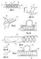
- Figure 1 is a perspective view of an intravascular stent formed according to a preferred embodiment of the present invention in a helical configuration in its relaxed state;
- Figure 1A graphically illustrates the possible phase changes of the stent of the present invention in both a deployed and non-deployed state;
- Figures 1B and 1C illustrate alternate cross-sections of the stent wire material;
- Figure 2 is an enlarged view of a portion of a stent according to a second preferred embodiment of the present invention;
- Figure 2A illustrates the stent of Figure 2 in a deployed state;
- Figure 3 is a side elevation view of the stent of Figure I inserted into a microinfusion catheter for intravascular placement according to the preferred embodiment of the present invention;
- Figure 4 illustrates the stent of Figure 3 fully deployed in a blood vessel adjacent an aneurysm, in addition to a balloon inflated within the stent;
- Figure 5 is a side view of an intravascular stent according to a third preferred embodiment of the present invention;
- Figure 6 is a side view of an intravascular stent according to a fourth preferred embodiment of the present invention;
- Figures 7 through 10 illustrate a preferred method of deployment of a stent according to the present invention; and
- Figure 11 is a side view of an intravascular stent system and embolic coil according to a fifth preferred embodiment of the present invention.
-
- The following description of the preferred embodiments of the present invention is merely illustrative in nature, and as such it does not limit in any way the present invention, its application, or uses. Numerous modifications may be made by those skilled in the art without departing from the true spirit and scope of the invention.
- Referring to Figure 1, a perspective view of a stent according to a first preferred embodiment of the present invention is shown generally at 10. The stent 10 may be used to reinforce diseased areas of a blood vessel, such as aneurysms, and for opening narrowed blood vessels to increase blood flow. The stent 10 is preferably formed from a single length of nickel-titanium alloy wire, which is available under the name of nitinol, or from any other suitable resilient material. The nitinol wire preferably has an austenitic phase transformation substantially below 37°C, as is shown at
reference numeral 11 in Figure 1A, thus giving the stent a relaxed resilient state at body temperature. The phase transformation behavior illustrated in Figure 1A is inherent to the nitinol material, and can be used for "shape memory" material applications. The present stent requires no shape memory attributes, and preferably remains in the resilient, or "super-elastic" phase. - Preferably, the nitinol wire is wound around a piece of threaded titanium in a helical configuration and heat-treated to form the stent in a relaxed state helical configuration as shown in Figure 1. Further, all or part of the wire material may be coated or covered with a radiopaque material, such as a platinum coating or very small platinum coil. This radiopaque material allows visualization of the stent while in the body of the patient, during insertion and after placement of the stent at the vessel site.
- The stent 10 preferably has a deployed diameter of approximately 0.039―0.393 inches, and has a deployment length of approximately 0.125―2.00 inches. However, the stent diameter and length may vary in size depending upon the particular application and the size of the blood vessel in which the stent is to be inserted. As shown in Figures 1B and 1C, the stent may have a substantially flat cross-section as shown at 10a, or a semi-circular or "D" shaped cross-section as shown at 10b, or any other cross-section as dictated by a particular application or anatomy.
- The stent 10 of the present invention includes a
proximal end 12 defining a stent passageway opening 14. The stentproximal end 12 may include abeaded tip 16 that provides a point at which a stent delivery device, such as the pusher mechanism shown at 18 in Figure 3, may be attached or engaged with the stent, to advance the stent through the vessel to the diseased vessel site. Thepusher mechanism 18 may be capable of selective engagement with the stentproximal bead 16, so that thepusher mechanism 18 can selectively release the stent at whatever location is desired. As a result, the stent can be more precisely placed before being released by thepusher mechanism 18, or may even be retracted back into the catheter if the stent is the wrong size or is positioned improperly. - The stent also includes a
body portion 20 extending from the proximal end in a helical configuration. Thebody portion 20 defines astent lumen 22 that allows passage of blood or other bodily fluids. Preferably, the helical configuration of the body portion has a characteristic pitch of approximately 0.003―0.250 inches, with the term "pitch" being defined as the center to center axial distance between adjacent coils in the helical configuration. - The stent also includes a
distal end 24 which terminates thebody portion 20 and which defines a second lumen opening 26 for thestent lumen 22. The distal end terminates at adistal tip 28, which may preferably have a bead to be atraumatic to the blood vessel into which the stent is inserted. - Referring to Figure 2, an enlarged section of a stent according to a second preferred embodiment of the present invention is shown generally at 30. The resilient wire of the stent is sealed between two sheets or strips of film or
mesh film 32 may be a thrombogenic film to aid in securing the stent to the wall of the vessel in which the stent is implemented. In contrast, the inner strip offilm 34 is preferably a non-thrombogenic film material to prevent thrombus within the stent lumen, so as not to inhibit blood flow. As shown in Figure 2A, after the stent exits the microcatheter, it forms a helical configuration with the edges of the attachedfilms tubular structure 38. The thrombogenic side of thefilm 32 is on the outside of thetubular structure 38, and the non-thrombogenic side of thefilm 34 is on the inside of thetubular structure 38. - Referring to Figures 3 and 4, the stent 10 is shown after being inserted into a
microcatheter 40 for deployment in a weakened or occluded area of avessel 42, such as aneck 43 of an aneurysm shown at 44. The stent 10 is pushed through themicrocatheter 40 by an operator manipulating the delivery device orpusher mechanism 18. Themicrocatheter 40 is of a type well known in the art and has a diameter smaller than that of the stent in its deployed configuration. For example, for a stent having a non-deployed or stretched linear wire diameter of 0.016 inches, the microcatheter used to deploy the stent would preferably have an inside diameter of about 0.020 inches, while the deployed diameter of the coiled stent could be much larger, perhaps as much as 0.157 inches. - The
microcatheter 40 delivers the stent in a substantially linear configuration while being delivered through the microcatheter, and releases the stent to its substantially helical configuration upon exiting themicrocatheter 40. - In the initial linear configuration, the stent can be delivered to a vessel location through a catheter having a diameter significantly smaller than that of the relaxed, deployed stent. The stent of the present invention thereby minimizes the diameter of the catheter in the vessel, and thereby facilitates deployment of a stent in small diameter vessels not currently treatable with tubular or cylindrical stents having the same deployed diameter.
- As shown in Figure 4, after being deployed in the vessel area, the stent returns to its relaxed helical configuration, thereby expanding to its normal diameter and tending to retain itself in position within the smaller
diameter blood vessel 42. Further, as shown in Figure 4, aballoon 50 of the type associated with conventional balloon microcatheters may also be utilized to aid in expanding or "tacking" the stent of the present invention. - Referring now to Figure 5, a double helix stent according to another embodiment of the present invention is shown generally at 60. The
counter helix stent 60 includes two individual lengths ofresilient wire wires stent 60 may be formed in a double helix configuration through use of a single length of wire or coil formed on a properly designed mandrel (not shown) having both right and left hand threads, by heat-treating a single length of resilient material to give the material a double helical configuration similar to that shown in Figure 5. Of course, a similar construction may be obtained by joining or welding the proximal or distal ends of thewires counter-helical stent 60. - The first
resilient wire 62 is wound in a right-hand threaded direction, while the secondresilient wire 64 is wound in a left-hand threaded direction. Each wire thus provides support for the other to resist collapse of thestent 60 in both radial and axial directions, upon the application of external forces. Thestent 60 may preferably include twodistal beads distal end 70, to be atraumatic to the vessel. In addition, both tips of theproximal end 72 may preferably be joined together at 74 to provide a point at which the stent can be advanced through a microcatheter using a pusher or a detachable pusher mechanism, such as that shown at 18 in Figure 3. - Referring now to Figure 6, a stent system according to another preferred embodiment of the present invention is shown generally at 80, in which the stent is further provided with a sleeve, covering or sheath. Such a sleeve is intended to more effectively treat and seal a particular vascular defect. The
stent 80 may be of a counter helix configuration similar to that ofstent 60 shown in Figure 5.Stent 80 in Figure 6 also includeselastic sleeve 82 within the twostents sleeve 82 may provide additional stent support for better occlusion of theneck 43 ofaneurysm 44 shown in Figure 4. Preferably, thesleeve 82 is attached between the twostents stent 84 and outsidestent 86. Thus, the stent system can still be collapsed to a substantially linear configuration when inserted into a catheter during placement and deployment of the stent. Alternatively, thesleeve 82 may be attached within, or outside, bothstents - Figures 7-10 illustrate the deployment of the stent of the present invention, with particular reference to the
counter-helix stent 60 in Figure 5. However, it should be understood that delivery and deployment of stents according to all of the preferred embodiments of the present invention are similar. Referring first to Figure 7, thestent 60 is inserted into themicrocatheter 40, and assumes a substantially deformed or stretched linear configuration as shown generally at 90. The microcatheter is then moved into close proximity to the vascular defect. in this case theneck 43 of ananeurysm 44. After being placed near theaneurysm 44, thestent 60 is pushed out of the distal end of the microcatheter by thepusher 92, and the microcatheter is withdrawn slightly in the proximal direction, as shown at 94 in Figure 8. Thestent 60 resiliently assumes its relaxed counter-helix configuration as shown at 94, while the portion of thestent 60 remaining within the microcatheter is held in a generally linear configuration as shown at 90. - Referring to Figure 9, once the stent is completely pushed out of the
microcatheter 40, the entire stent reassumes its relaxed helical configuration. Thestent 60 in its relaxed configuration has an associated diameter that tends to be somewhat greater than the diameter of thevessel 42, causing thestent 60 to gently press outward against the wall of thevessel 42. Therefore, thestent 60 tends to hold itself in place at the desired location across the vascular defect, such as theaneurysm 44. - However, as shown in Figure 10, if it is determined that the stent has been incorrectly positioned, the stent may be withdrawn back into the catheter, as indicated at 100, thus becoming stretched again to a substantially linear configuration with an associated smaller diameter. Once the stent has been withdrawn into the microcatheter, the microcatheter may be repositioned within the blood vessel to thereby effectively reposition the stent properly in the desired position.
- As depicted in Figure 11, a vascular defect such as
aneurysm 118 may develop at a location where one vessel branches off from another, referred to as a vessel "bifurcation," such as that shown generally at 116. A stent system for treating this type of vascular defect near a bifurcation is shown generally at 110, according to another preferred embodiment of the present invention. - The
stent system 110 consists essentially of twoindividual wire stents Wire stents stents aneurysm 118. - The
stent 114 is placed in interlocking contact across thestent 112, with the proximal portions ofstents counter helix stent 60 shown in Figure 5. Thestent system 110 thereby forms the desired lumens, and adds structural integrity to the vessels at the bifurcation aneurysm, that would not otherwise be possible with a single stent. - Moreover, it is desirable to fill the
bifurcation aneurysm 118 with embolic agents, such asembolic coils 122, to embolize the aneurysm and reduce the pressure inside. Only a fewembolic coils 122 are illustrated in Figure 11 for the sake of clarity, though the aneurysm would preferably be filled with a sufficient number ofembolic coils 122 to successfully embolize the aneurysm. Depending on the particular anatomy of a patient, the number ofembolic coils 122 that might be required may vary from one to many. - It is also important to prevent the embolic agent or coils from escaping the aneurysm, which might cause embolization in an undesirable location. The
stent system 110 of the present invention forms a shelf near theneck 116 of thebifurcation aneurysm 118, on which the embolic devices can rest. This important feature of the present invention thus enables the successful treatment of a bifurcation aneurysm. - From the foregoing description, it should be appreciated that according to the preferred embodiments of the present invention the stent is collapsible to a compressed, substantially linear configuration for delivery and deployment in a tissue vessel. The positioning and deployment of the stent of the present invention thereby may be performed with a lower level of associated trauma to the vessel, and can be realized in vessels having a significantly smaller diameter than has been possible before with conventional stents. The stent of the present invention may be configured in a counter helix configuration, a configuration having a mesh cover, or in a bifurcated configuration to adapt the stent to particular application needs, while maintaining the collapsibility and deployability characteristics associated with the resilient material from which it is configured.
- It should be understood that an unlimited number of configurations for the present invention can be realized. The foregoing discussion describes merely exemplary embodiments illustrating the principles of the present invention, the scope of which is recited in the following claims. Those skilled in the art will readily recognize from the description, claims, and drawings that numerous changes and modifications can be made without departing from the spirit and scope of the invention.
Claims (4)
- A vascular stent system (80) for treating a blood vessel defect comprising:a first stent (84) formed of a resilient wire (62, 64) having a helical shape in a relaxed state, said stent having a predetermined pitch and in which the stent (84) may be stretched into a substantially linear shape and has a tendency to return to the relaxed helical shape; anda second stent (86) formed substantially identical to the first stent (84), having a helical shape in a relaxed state and the second stent (86) may be stretched into a substantially linear shape and has a tendency to return to the relaxed helical shape, the second stent (86) forming a dual helix with the first stent (84) when placed within a blood vessel to provide support at a vascular site; characterised bythe first and second stents (84, 86) being joined at one end (74) and the first stent (84) having a clockwise helical relaxed shape and the second stent (86) having a counter clockwise helical relaxed shape; anda cover over at least a portion of the first stent (84) for providing support for a vessel at a vascular site, wherein said cover comprises a sheath (82) extending longitudinally outside the first stent (84) and inside the second stent (86).
- The vascular stent system of claim 1, wherein the sheath (82) is formed of a mesh material.
- The vascular stent system of claim 1 or claim 2, wherein the sheath (82) is formed of an elastic material.
- The vascular stent system of claim 1, 2, or 3, wherein the sheath (82) is cylindrical.
Applications Claiming Priority (3)
| Application Number | Priority Date | Filing Date | Title |
|---|---|---|---|
| US09/052,402 US6063111A (en) | 1998-03-31 | 1998-03-31 | Stent aneurysm treatment system and method |
| US52402 | 1998-03-31 | ||
| EP99302500A EP0947180B1 (en) | 1998-03-31 | 1999-03-30 | Stent aneurysm treatment system |
Related Parent Applications (1)
| Application Number | Title | Priority Date | Filing Date |
|---|---|---|---|
| EP99302500A Division EP0947180B1 (en) | 1998-03-31 | 1999-03-30 | Stent aneurysm treatment system |
Publications (2)
| Publication Number | Publication Date |
|---|---|
| EP1527756A2 true EP1527756A2 (en) | 2005-05-04 |
| EP1527756A3 EP1527756A3 (en) | 2007-12-05 |
Family
ID=21977385
Family Applications (2)
| Application Number | Title | Priority Date | Filing Date |
|---|---|---|---|
| EP99302500A Expired - Lifetime EP0947180B1 (en) | 1998-03-31 | 1999-03-30 | Stent aneurysm treatment system |
| EP05075128A Withdrawn EP1527756A3 (en) | 1998-03-31 | 1999-03-30 | Stent aneurysm treatment system and method |
Family Applications Before (1)
| Application Number | Title | Priority Date | Filing Date |
|---|---|---|---|
| EP99302500A Expired - Lifetime EP0947180B1 (en) | 1998-03-31 | 1999-03-30 | Stent aneurysm treatment system |
Country Status (3)
| Country | Link |
|---|---|
| US (2) | US6063111A (en) |
| EP (2) | EP0947180B1 (en) |
| DE (1) | DE69933078T2 (en) |
Cited By (3)
| Publication number | Priority date | Publication date | Assignee | Title |
|---|---|---|---|---|
| WO2007140566A2 (en) * | 2006-06-06 | 2007-12-13 | Luiz Gonzaga Granja Filho | Prothesis for laparoscopic anastomosis |
| EP2098174A2 (en) * | 2008-03-05 | 2009-09-09 | Neurovasx, Inc. | Multiple biocompatible polymeric strand aneurysm embolization system and method |
| US8641748B2 (en) | 2002-02-28 | 2014-02-04 | Bay Street Medical, Inc. | Guidewire loaded stent for delivery through a catheter |
Families Citing this family (258)
| Publication number | Priority date | Publication date | Assignee | Title |
|---|---|---|---|---|
| US6039749A (en) | 1994-02-10 | 2000-03-21 | Endovascular Systems, Inc. | Method and apparatus for deploying non-circular stents and graftstent complexes |
| US7204848B1 (en) | 1995-03-01 | 2007-04-17 | Boston Scientific Scimed, Inc. | Longitudinally flexible expandable stent |
| US6451047B2 (en) | 1995-03-10 | 2002-09-17 | Impra, Inc. | Encapsulated intraluminal stent-graft and methods of making same |
| US6264684B1 (en) | 1995-03-10 | 2001-07-24 | Impra, Inc., A Subsidiary Of C.R. Bard, Inc. | Helically supported graft |
| US7959664B2 (en) * | 1996-12-26 | 2011-06-14 | Medinol, Ltd. | Flat process of drug coating for stents |
| US6425915B1 (en) * | 1997-03-18 | 2002-07-30 | Endotex Interventional Systems, Inc. | Helical mesh endoprosthesis and methods of use |
| US20040130599A1 (en) * | 1997-07-15 | 2004-07-08 | Silverbrook Research Pty Ltd | Ink jet printhead with amorphous ceramic chamber |
| US6070589A (en) | 1997-08-01 | 2000-06-06 | Teramed, Inc. | Methods for deploying bypass graft stents |
| US20070142901A1 (en) * | 1998-02-17 | 2007-06-21 | Steinke Thomas A | Expandable stent with sliding and locking radial elements |
| US7500988B1 (en) | 2000-11-16 | 2009-03-10 | Cordis Corporation | Stent for use in a stent graft |
| US6290731B1 (en) | 1998-03-30 | 2001-09-18 | Cordis Corporation | Aortic graft having a precursor gasket for repairing an abdominal aortic aneurysm |
| US6063111A (en) * | 1998-03-31 | 2000-05-16 | Cordis Corporation | Stent aneurysm treatment system and method |
| US6285903B1 (en) * | 1998-06-30 | 2001-09-04 | Eclipse Surgical Technologies, Inc. | Intracorporeal device with radiopaque marker |
| US6656218B1 (en) * | 1998-07-24 | 2003-12-02 | Micrus Corporation | Intravascular flow modifier and reinforcement device |
| US6254612B1 (en) | 1998-10-22 | 2001-07-03 | Cordis Neurovascular, Inc. | Hydraulic stent deployment system |
| EP1152711B1 (en) * | 1999-01-27 | 2005-07-06 | Boston Scientific Limited | Bifurcation stent delivery system |
| US6398803B1 (en) | 1999-02-02 | 2002-06-04 | Impra, Inc., A Subsidiary Of C.R. Bard, Inc. | Partial encapsulation of stents |
| US6613074B1 (en) | 1999-03-10 | 2003-09-02 | Cordis Corporation | Endovascular aneurysm embolization device |
| US20020169473A1 (en) * | 1999-06-02 | 2002-11-14 | Concentric Medical, Inc. | Devices and methods for treating vascular malformations |
| US6364904B1 (en) * | 1999-07-02 | 2002-04-02 | Scimed Life Systems, Inc. | Helically formed stent/graft assembly |
| US7815590B2 (en) * | 1999-08-05 | 2010-10-19 | Broncus Technologies, Inc. | Devices for maintaining patency of surgically created channels in tissue |
| US7422563B2 (en) * | 1999-08-05 | 2008-09-09 | Broncus Technologies, Inc. | Multifunctional tip catheter for applying energy to tissue and detecting the presence of blood flow |
| US6692494B1 (en) * | 1999-08-05 | 2004-02-17 | Broncus Technologies, Inc. | Methods and devices for creating collateral channels in the lungs |
| US7175644B2 (en) * | 2001-02-14 | 2007-02-13 | Broncus Technologies, Inc. | Devices and methods for maintaining collateral channels in tissue |
| GB0003387D0 (en) | 2000-02-14 | 2000-04-05 | Angiomed Ag | Stent matrix |
| US20020128701A1 (en) * | 2000-04-28 | 2002-09-12 | Winters R. Edward | Low profile expandable hoop support device for flexible tubes |
| US6554849B1 (en) * | 2000-09-11 | 2003-04-29 | Cordis Corporation | Intravascular embolization device |
| US6945989B1 (en) * | 2000-09-18 | 2005-09-20 | Endotex Interventional Systems, Inc. | Apparatus for delivering endoluminal prostheses and methods of making and using them |
| US7037330B1 (en) | 2000-10-16 | 2006-05-02 | Scimed Life Systems, Inc. | Neurovascular stent and method |
| US6743251B1 (en) * | 2000-11-15 | 2004-06-01 | Scimed Life Systems, Inc. | Implantable devices with polymeric detachment junction |
| US6648911B1 (en) * | 2000-11-20 | 2003-11-18 | Avantec Vascular Corporation | Method and device for the treatment of vulnerable tissue site |
| US6579308B1 (en) * | 2000-11-28 | 2003-06-17 | Scimed Life Systems, Inc. | Stent devices with detachable distal or proximal wires |
| US6641607B1 (en) | 2000-12-29 | 2003-11-04 | Advanced Cardiovascular Systems, Inc. | Double tube stent |
| US20010044650A1 (en) * | 2001-01-12 | 2001-11-22 | Simso Eric J. | Stent for in-stent restenosis |
| WO2002067815A1 (en) * | 2001-02-26 | 2002-09-06 | Scimed Life Systems, Inc. | Bifurcated stent |
| US6585753B2 (en) * | 2001-03-28 | 2003-07-01 | Scimed Life Systems, Inc. | Expandable coil stent |
| US6921410B2 (en) * | 2001-05-29 | 2005-07-26 | Scimed Life Systems, Inc. | Injection molded vaso-occlusive elements |
| US6673106B2 (en) | 2001-06-14 | 2004-01-06 | Cordis Neurovascular, Inc. | Intravascular stent device |
| US6818013B2 (en) * | 2001-06-14 | 2004-11-16 | Cordis Corporation | Intravascular stent device |
| US20040172769A1 (en) * | 2001-06-20 | 2004-09-09 | Giddings Daniel G. | Method and apparatus for cleaning fabrics, floor coverings, and bare floor surfaces utilizing a soil transfer cleaning medium |
| US20030014075A1 (en) * | 2001-07-16 | 2003-01-16 | Microvention, Inc. | Methods, materials and apparatus for deterring or preventing endoleaks following endovascular graft implanation |
| US8252040B2 (en) | 2001-07-20 | 2012-08-28 | Microvention, Inc. | Aneurysm treatment device and method of use |
| US7572288B2 (en) * | 2001-07-20 | 2009-08-11 | Microvention, Inc. | Aneurysm treatment device and method of use |
| US8715312B2 (en) * | 2001-07-20 | 2014-05-06 | Microvention, Inc. | Aneurysm treatment device and method of use |
| US7708712B2 (en) | 2001-09-04 | 2010-05-04 | Broncus Technologies, Inc. | Methods and devices for maintaining patency of surgically created channels in a body organ |
| GB0121980D0 (en) * | 2001-09-11 | 2001-10-31 | Cathnet Science Holding As | Expandable stent |
| US6802851B2 (en) * | 2001-09-20 | 2004-10-12 | Gordia Neurovascular, Inc. | Stent aneurysm embolization method using collapsible member and embolic coils |
| US6811560B2 (en) * | 2001-09-20 | 2004-11-02 | Cordis Neurovascular, Inc. | Stent aneurysm embolization method and device |
| JP4429589B2 (en) * | 2001-11-15 | 2010-03-10 | コーディス・ニューロバスキュラー・インコーポレイテッド | Aneurysm embolization device using an occluding member |
| US6989020B2 (en) * | 2001-11-15 | 2006-01-24 | Cordis Neurovascular, Inc. | Embolic coil retrieval system |
| JP2003190175A (en) * | 2001-11-15 | 2003-07-08 | Cordis Neurovascular Inc | Aneurysm neck cover for sealing aneurysm |
| GB2384189A (en) * | 2001-11-21 | 2003-07-23 | Tayside Flow Technologies Ltd | Helix shaped insert for flow moification in a duct or stent |
| US20030135266A1 (en) | 2001-12-03 | 2003-07-17 | Xtent, Inc. | Apparatus and methods for delivery of multiple distributed stents |
| US20040186551A1 (en) | 2003-01-17 | 2004-09-23 | Xtent, Inc. | Multiple independent nested stent structures and methods for their preparation and deployment |
| US7270668B2 (en) * | 2001-12-03 | 2007-09-18 | Xtent, Inc. | Apparatus and methods for delivering coiled prostheses |
| US8080048B2 (en) | 2001-12-03 | 2011-12-20 | Xtent, Inc. | Stent delivery for bifurcated vessels |
| US7182779B2 (en) | 2001-12-03 | 2007-02-27 | Xtent, Inc. | Apparatus and methods for positioning prostheses for deployment from a catheter |
| US7137993B2 (en) | 2001-12-03 | 2006-11-21 | Xtent, Inc. | Apparatus and methods for delivery of multiple distributed stents |
| US7294146B2 (en) | 2001-12-03 | 2007-11-13 | Xtent, Inc. | Apparatus and methods for delivery of variable length stents |
| US7892273B2 (en) | 2001-12-03 | 2011-02-22 | Xtent, Inc. | Custom length stent apparatus |
| US7351255B2 (en) | 2001-12-03 | 2008-04-01 | Xtent, Inc. | Stent delivery apparatus and method |
| US7147656B2 (en) | 2001-12-03 | 2006-12-12 | Xtent, Inc. | Apparatus and methods for delivery of braided prostheses |
| US7309350B2 (en) | 2001-12-03 | 2007-12-18 | Xtent, Inc. | Apparatus and methods for deployment of vascular prostheses |
| US20030195609A1 (en) * | 2002-04-10 | 2003-10-16 | Scimed Life Systems, Inc. | Hybrid stent |
| US7195648B2 (en) | 2002-05-16 | 2007-03-27 | Cordis Neurovascular, Inc. | Intravascular stent device |
| IL149829A (en) * | 2002-05-23 | 2012-10-31 | Ronnie Levi | Medical device having an unravelable portion |
| US6833003B2 (en) * | 2002-06-24 | 2004-12-21 | Cordis Neurovascular | Expandable stent and delivery system |
| US7485122B2 (en) * | 2002-06-27 | 2009-02-03 | Boston Scientific Scimed, Inc. | Integrated anchor coil in stretch-resistant vaso-occlusive coils |
| DE10233085B4 (en) * | 2002-07-19 | 2014-02-20 | Dendron Gmbh | Stent with guide wire |
| US8425549B2 (en) | 2002-07-23 | 2013-04-23 | Reverse Medical Corporation | Systems and methods for removing obstructive matter from body lumens and treating vascular defects |
| US20050171572A1 (en) * | 2002-07-31 | 2005-08-04 | Microvention, Inc. | Multi-layer coaxial vaso-occlusive device |
| US20040044391A1 (en) * | 2002-08-29 | 2004-03-04 | Stephen Porter | Device for closure of a vascular defect and method of treating the same |
| US7001422B2 (en) * | 2002-09-23 | 2006-02-21 | Cordis Neurovascular, Inc | Expandable stent and delivery system |
| US7240677B2 (en) * | 2003-02-03 | 2007-07-10 | Biomedical Enterprises, Inc. | System and method for force, displacement, and rate control of shaped memory material implants |
| US20040193246A1 (en) * | 2003-03-25 | 2004-09-30 | Microvention, Inc. | Methods and apparatus for treating aneurysms and other vascular defects |
| DE602004010895T2 (en) * | 2003-04-02 | 2008-12-11 | Boston Scientific Ltd., St. Michael | REMOVABLE AND RETRACTABLE STENT ARRANGEMENT |
| US7241308B2 (en) | 2003-06-09 | 2007-07-10 | Xtent, Inc. | Stent deployment systems and methods |
| US20040260384A1 (en) * | 2003-06-17 | 2004-12-23 | Medtronic Ave | Superelastic coiled stent |
| US8002740B2 (en) * | 2003-07-18 | 2011-08-23 | Broncus Technologies, Inc. | Devices for maintaining patency of surgically created channels in tissue |
| US8308682B2 (en) | 2003-07-18 | 2012-11-13 | Broncus Medical Inc. | Devices for maintaining patency of surgically created channels in tissue |
| US8043321B2 (en) * | 2003-07-24 | 2011-10-25 | Boston Scientific Scimed, Inc. | Embolic coil |
| US20050107823A1 (en) * | 2003-11-19 | 2005-05-19 | Leone Jim E. | Anchored stent and occlusive device for treatment of aneurysms |
| US7326236B2 (en) | 2003-12-23 | 2008-02-05 | Xtent, Inc. | Devices and methods for controlling and indicating the length of an interventional element |
| US20070156225A1 (en) * | 2003-12-23 | 2007-07-05 | Xtent, Inc. | Automated control mechanisms and methods for custom length stent apparatus |
| US7402170B2 (en) * | 2003-12-30 | 2008-07-22 | Scimed Life Systems, Inc. | Crimp and weld wire connection |
| US20050185061A1 (en) * | 2004-02-23 | 2005-08-25 | Andy Baker | Self photographing camera system |
| US20050203606A1 (en) * | 2004-03-09 | 2005-09-15 | Vancamp Daniel H. | Stent system for preventing restenosis |
| GB0406719D0 (en) * | 2004-03-25 | 2004-04-28 | Tayside Flow Technologies Ltd | A tubular conduit |
| US7323006B2 (en) | 2004-03-30 | 2008-01-29 | Xtent, Inc. | Rapid exchange interventional devices and methods |
| WO2010120926A1 (en) | 2004-05-25 | 2010-10-21 | Chestnut Medical Technologies, Inc. | Vascular stenting for aneurysms |
| US8267985B2 (en) | 2005-05-25 | 2012-09-18 | Tyco Healthcare Group Lp | System and method for delivering and deploying an occluding device within a vessel |
| US8628564B2 (en) | 2004-05-25 | 2014-01-14 | Covidien Lp | Methods and apparatus for luminal stenting |
| US8617234B2 (en) | 2004-05-25 | 2013-12-31 | Covidien Lp | Flexible vascular occluding device |
| US20060206200A1 (en) | 2004-05-25 | 2006-09-14 | Chestnut Medical Technologies, Inc. | Flexible vascular occluding device |
| JP2008502378A (en) | 2004-05-25 | 2008-01-31 | チェストナット メディカル テクノロジーズ インコーポレイテッド | Flexible vascular closure device |
| US20050278017A1 (en) * | 2004-06-09 | 2005-12-15 | Scimed Life Systems, Inc. | Overlapped stents for scaffolding, flexibility and MRI compatibility |
| US20050288766A1 (en) * | 2004-06-28 | 2005-12-29 | Xtent, Inc. | Devices and methods for controlling expandable prostheses during deployment |
| US8317859B2 (en) | 2004-06-28 | 2012-11-27 | J.W. Medical Systems Ltd. | Devices and methods for controlling expandable prostheses during deployment |
| US8409167B2 (en) | 2004-07-19 | 2013-04-02 | Broncus Medical Inc | Devices for delivering substances through an extra-anatomic opening created in an airway |
| US7763065B2 (en) | 2004-07-21 | 2010-07-27 | Reva Medical, Inc. | Balloon expandable crush-recoverable stent device |
| US20060020285A1 (en) * | 2004-07-22 | 2006-01-26 | Volker Niermann | Method for filtering blood in a vessel with helical elements |
| US20060020286A1 (en) * | 2004-07-22 | 2006-01-26 | Volker Niermann | Device for filtering blood in a vessel with helical elements |
| US20060030929A1 (en) * | 2004-08-09 | 2006-02-09 | Scimed Life Systems, Inc. | Flap-cover aneurysm stent |
| EP1788956B1 (en) | 2004-09-17 | 2011-11-09 | Codman & Shurtleff, Inc. | Vascular occlusion device with an embolic mesh ribbon |
| US20060064064A1 (en) * | 2004-09-17 | 2006-03-23 | Jang G D | Two-step/dual-diameter balloon angioplasty catheter for bifurcation and side-branch vascular anatomy |
| US7914570B2 (en) * | 2004-10-07 | 2011-03-29 | Boston Scientific Scimed, Inc. | Non-shortening helical stent |
| US8535345B2 (en) | 2004-10-07 | 2013-09-17 | DePuy Synthes Products, LLC | Vasoocclusive coil with biplex windings to improve mechanical properties |
| US8292944B2 (en) | 2004-12-17 | 2012-10-23 | Reva Medical, Inc. | Slide-and-lock stent |
| US20080188803A1 (en) * | 2005-02-03 | 2008-08-07 | Jang G David | Triple-profile balloon catheter |
| WO2006082493A2 (en) * | 2005-02-04 | 2006-08-10 | Zuli Holdings, Ltd. | Device and methods for non-surgical clipping of aneurysms |
| US20060206198A1 (en) * | 2005-03-12 | 2006-09-14 | Churchwell Stacey D | Aneurysm treatment devices and methods |
| US20060206199A1 (en) * | 2005-03-12 | 2006-09-14 | Churchwell Stacey D | Aneurysm treatment devices |
| US10070977B2 (en) | 2005-05-24 | 2018-09-11 | Inspire M.D. Ltd | Stent apparatuses for treatment via body lumens and methods of use |
| US8961586B2 (en) * | 2005-05-24 | 2015-02-24 | Inspiremd Ltd. | Bifurcated stent assemblies |
| US8043323B2 (en) | 2006-10-18 | 2011-10-25 | Inspiremd Ltd. | In vivo filter assembly |
| AU2005332044B2 (en) | 2005-05-25 | 2012-01-19 | Covidien Lp | System and method for delivering and deploying and occluding device within a vessel |
| US8273101B2 (en) | 2005-05-25 | 2012-09-25 | Tyco Healthcare Group Lp | System and method for delivering and deploying an occluding device within a vessel |
| US8157851B2 (en) * | 2005-06-08 | 2012-04-17 | Xtent, Inc. | Apparatus and methods for deployment of multiple custom-length prostheses |
| US9149378B2 (en) | 2005-08-02 | 2015-10-06 | Reva Medical, Inc. | Axially nested slide and lock expandable device |
| US7914574B2 (en) | 2005-08-02 | 2011-03-29 | Reva Medical, Inc. | Axially nested slide and lock expandable device |
| US8043366B2 (en) | 2005-09-08 | 2011-10-25 | Boston Scientific Scimed, Inc. | Overlapping stent |
| DE102005052226B4 (en) * | 2005-09-30 | 2014-09-11 | Michael Friebe | Stent for insertion into human body cavities, especially in blood vessels |
| CA2625826C (en) | 2005-10-19 | 2014-08-05 | Pulsar Vascular, Inc. | Methods and systems for endovascularly clipping and repairing lumen and tissue defects |
| US20070112418A1 (en) * | 2005-11-14 | 2007-05-17 | Boston Scientific Scimed, Inc. | Stent with spiral side-branch support designs |
| WO2007100556A1 (en) | 2006-02-22 | 2007-09-07 | Ev3 Inc. | Embolic protection systems having radiopaque filter mesh |
| US9402633B2 (en) | 2006-03-13 | 2016-08-02 | Pneumrx, Inc. | Torque alleviating intra-airway lung volume reduction compressive implant structures |
| US8157837B2 (en) | 2006-03-13 | 2012-04-17 | Pneumrx, Inc. | Minimally invasive lung volume reduction device and method |
| US8888800B2 (en) | 2006-03-13 | 2014-11-18 | Pneumrx, Inc. | Lung volume reduction devices, methods, and systems |
| US8828077B2 (en) | 2006-03-15 | 2014-09-09 | Medinol Ltd. | Flat process of preparing drug eluting stents |
| JP2009530060A (en) | 2006-03-20 | 2009-08-27 | エックステント・インコーポレーテッド | Apparatus and method for deploying connected prosthetic segments |
| US20070225799A1 (en) * | 2006-03-24 | 2007-09-27 | Medtronic Vascular, Inc. | Stent, intraluminal stent delivery system, and method of treating a vascular condition |
| US20070239255A1 (en) * | 2006-04-07 | 2007-10-11 | Richard Allen Hines | System and device for helical stent delivery |
| US9561351B2 (en) * | 2006-05-31 | 2017-02-07 | Advanced Cardiovascular Systems, Inc. | Drug delivery spiral coil construct |
| US20100324664A1 (en) * | 2006-10-18 | 2010-12-23 | Asher Holzer | Bifurcated Stent Assemblies |
| US10137015B2 (en) * | 2006-10-18 | 2018-11-27 | Inspiremd Ltd. | Knitted stent jackets |
| WO2008047368A2 (en) * | 2006-10-18 | 2008-04-24 | Inspiremd Ltd. | Filter assemblies |
| US20080269774A1 (en) | 2006-10-26 | 2008-10-30 | Chestnut Medical Technologies, Inc. | Intracorporeal Grasping Device |
| JP2010508910A (en) * | 2006-11-02 | 2010-03-25 | アール. ショーン パクバズ, | Devices and methods for accessing and treating aneurysms |
| CN101578078B (en) | 2006-11-22 | 2013-01-02 | 印斯拜尔Md有限公司 | Optimized stent jacket |
| US7704275B2 (en) | 2007-01-26 | 2010-04-27 | Reva Medical, Inc. | Circumferentially nested expandable device |
| US20080199510A1 (en) | 2007-02-20 | 2008-08-21 | Xtent, Inc. | Thermo-mechanically controlled implants and methods of use |
| US8486132B2 (en) | 2007-03-22 | 2013-07-16 | J.W. Medical Systems Ltd. | Devices and methods for controlling expandable prostheses during deployment |
| US20080255654A1 (en) * | 2007-03-22 | 2008-10-16 | Bay Street Medical | System for delivering a stent |
| US20100121350A1 (en) * | 2007-04-12 | 2010-05-13 | Greg Mirigian | Instantaneous mechanical detachment mechanism for vaso-occlusive devices |
| US20080300667A1 (en) * | 2007-05-31 | 2008-12-04 | Bay Street Medical | System for delivering a stent |
| WO2009003049A2 (en) | 2007-06-25 | 2008-12-31 | Micro Vention, Inc. | Self-expanding prosthesis |
| US20090099591A1 (en) * | 2007-10-15 | 2009-04-16 | Boston Scientific Scimed, Inc. | Coil Anchor Systems and Methods of Use |
| US8585713B2 (en) | 2007-10-17 | 2013-11-19 | Covidien Lp | Expandable tip assembly for thrombus management |
| US8088140B2 (en) | 2008-05-19 | 2012-01-03 | Mindframe, Inc. | Blood flow restorative and embolus removal methods |
| US9220522B2 (en) | 2007-10-17 | 2015-12-29 | Covidien Lp | Embolus removal systems with baskets |
| US10123803B2 (en) | 2007-10-17 | 2018-11-13 | Covidien Lp | Methods of managing neurovascular obstructions |
| US11337714B2 (en) | 2007-10-17 | 2022-05-24 | Covidien Lp | Restoring blood flow and clot removal during acute ischemic stroke |
| US9198687B2 (en) | 2007-10-17 | 2015-12-01 | Covidien Lp | Acute stroke revascularization/recanalization systems processes and products thereby |
| US8066757B2 (en) | 2007-10-17 | 2011-11-29 | Mindframe, Inc. | Blood flow restoration and thrombus management methods |
| US8926680B2 (en) | 2007-11-12 | 2015-01-06 | Covidien Lp | Aneurysm neck bridging processes with revascularization systems methods and products thereby |
| US7988721B2 (en) | 2007-11-30 | 2011-08-02 | Reva Medical, Inc. | Axially-radially nested expandable device |
| US8956475B2 (en) | 2007-12-11 | 2015-02-17 | Howard Riina | Method and apparatus for restricting flow through an opening in the side wall of a body lumen, and/or for reinforcing a weakness in the side wall of a body lumen, while still maintaining substantially normal flow through the body lumen |
| WO2009088953A2 (en) | 2007-12-31 | 2009-07-16 | Boston Scientific Scimed Inc. | Bifurcation stent delivery system and methods |
| KR101819554B1 (en) | 2008-02-22 | 2018-01-17 | 마이크로 테라퓨틱스 인코포레이티드 | Methods and apparatus for flow restoration |
| US9101503B2 (en) | 2008-03-06 | 2015-08-11 | J.W. Medical Systems Ltd. | Apparatus having variable strut length and methods of use |
| CN101977650A (en) | 2008-04-11 | 2011-02-16 | 曼德弗雷姆公司 | Monorail neuro-microcatheter for delivery of medical devices to treat stroke, processes and products thereby |
| EP2633823B1 (en) * | 2008-04-21 | 2016-06-01 | Covidien LP | Braid-ball embolic devices and delivery systems |
| WO2009132141A1 (en) * | 2008-04-22 | 2009-10-29 | Coherex Medical, Inc. | Device, system and method for aneurysm embolization |
| US8702746B2 (en) * | 2008-04-29 | 2014-04-22 | Cook Medical Technologies Llc | Device and method for occlusion of fluid flow through a body vessel |
| US10716573B2 (en) | 2008-05-01 | 2020-07-21 | Aneuclose | Janjua aneurysm net with a resilient neck-bridging portion for occluding a cerebral aneurysm |
| US10028747B2 (en) | 2008-05-01 | 2018-07-24 | Aneuclose Llc | Coils with a series of proximally-and-distally-connected loops for occluding a cerebral aneurysm |
| CN102083493A (en) * | 2008-05-01 | 2011-06-01 | 安纽克罗斯有限责任公司 | Aneurysm occlusion device |
| US9675482B2 (en) | 2008-05-13 | 2017-06-13 | Covidien Lp | Braid implant delivery systems |
| US8377108B2 (en) | 2008-06-02 | 2013-02-19 | Boston Scientific Scimed, Inc. | Staggered two balloon bifurcation catheter assembly and methods |
| CA2731735A1 (en) * | 2008-07-22 | 2010-01-28 | Microtherapeutics, Inc. | Vascular remodeling device |
| US8388650B2 (en) | 2008-09-05 | 2013-03-05 | Pulsar Vascular, Inc. | Systems and methods for supporting or occluding a physiological opening or cavity |
| US9173669B2 (en) | 2008-09-12 | 2015-11-03 | Pneumrx, Inc. | Enhanced efficacy lung volume reduction devices, methods, and systems |
| US8769796B2 (en) | 2008-09-25 | 2014-07-08 | Advanced Bifurcation Systems, Inc. | Selective stent crimping |
| CN102215780B (en) | 2008-09-25 | 2015-10-14 | 高级分支系统股份有限公司 | Part crimped stent |
| US8795347B2 (en) | 2008-09-25 | 2014-08-05 | Advanced Bifurcation Systems, Inc. | Methods and systems for treating a bifurcation with provisional side branch stenting |
| US8821562B2 (en) | 2008-09-25 | 2014-09-02 | Advanced Bifurcation Systems, Inc. | Partially crimped stent |
| US11298252B2 (en) | 2008-09-25 | 2022-04-12 | Advanced Bifurcation Systems Inc. | Stent alignment during treatment of a bifurcation |
| CA2737753C (en) | 2008-10-10 | 2017-03-14 | Reva Medical, Inc. | Expandable slide and lock stent |
| US8470013B2 (en) * | 2008-10-20 | 2013-06-25 | Imds Corporation | Systems and methods for aneurysm treatment and vessel occlusion |
| US20100131002A1 (en) * | 2008-11-24 | 2010-05-27 | Connor Robert A | Stent with a net layer to embolize and aneurysm |
| GB0900565D0 (en) | 2009-01-14 | 2009-02-11 | Isis Innovation | Stent |
| US20100268251A1 (en) * | 2009-04-16 | 2010-10-21 | Boston Scientific Scimed, Inc. | Delivery wire for occlusive device delivery system and method of manufacture |
| JP2012525239A (en) | 2009-05-01 | 2012-10-22 | エンドロジックス、インク | Transcutaneous methods and devices for treating dissociation (priority information and incorporation by reference) |
| US10772717B2 (en) | 2009-05-01 | 2020-09-15 | Endologix, Inc. | Percutaneous method and device to treat dissections |
| CN104622599B (en) * | 2009-05-18 | 2017-04-12 | 纽姆克斯股份有限公司 | Cross-sectional modification during deployment of an elongate lung volume reduction device |
| KR101788338B1 (en) | 2009-09-04 | 2017-10-19 | 펄사 배스큘라, 아이엔씨. | Systems and methods for enclosing an anatomical opening |
| EP2292147B1 (en) * | 2009-09-07 | 2012-11-07 | Aeeg Ab | Device and kit for closure of a body lumen puncture |
| US20110202085A1 (en) | 2009-11-09 | 2011-08-18 | Siddharth Loganathan | Braid Ball Embolic Device Features |
| US9155640B2 (en) * | 2009-11-16 | 2015-10-13 | Tre′ Raymond Welch | Stent and method for manufacturing thereof |
| US9358140B1 (en) | 2009-11-18 | 2016-06-07 | Aneuclose Llc | Stent with outer member to embolize an aneurysm |
| US8906057B2 (en) * | 2010-01-04 | 2014-12-09 | Aneuclose Llc | Aneurysm embolization by rotational accumulation of mass |
| US9468442B2 (en) * | 2010-01-28 | 2016-10-18 | Covidien Lp | Vascular remodeling device |
| EP2528541B1 (en) * | 2010-01-28 | 2016-05-18 | Covidien LP | Vascular remodeling device |
| WO2011119883A1 (en) | 2010-03-24 | 2011-09-29 | Advanced Bifurcation Systems, Inc. | Stent alignment during treatment of a bifurcation |
| CA2794080A1 (en) | 2010-03-24 | 2011-09-29 | Advanced Bifurcation Systems, Inc. | System and methods for treating a bifurcation |
| CA2795292A1 (en) | 2010-04-10 | 2011-10-13 | Reva Medical, Inc. | Expandable slide and lock stent |
| US9247942B2 (en) | 2010-06-29 | 2016-02-02 | Artventive Medical Group, Inc. | Reversible tubal contraceptive device |
| WO2012002944A1 (en) | 2010-06-29 | 2012-01-05 | Artventive Medical Group, Inc. | Reducing flow through a tubular structure |
| US8425548B2 (en) | 2010-07-01 | 2013-04-23 | Aneaclose LLC | Occluding member expansion and then stent expansion for aneurysm treatment |
| US9039749B2 (en) | 2010-10-01 | 2015-05-26 | Covidien Lp | Methods and apparatuses for flow restoration and implanting members in the human body |
| US9149277B2 (en) | 2010-10-18 | 2015-10-06 | Artventive Medical Group, Inc. | Expandable device delivery |
| WO2012109382A2 (en) | 2011-02-08 | 2012-08-16 | Advanced Bifurcation Systems, Inc. | Multi-stent and multi-balloon apparatus for treating bifurcations and methods of use |
| EP2672932B1 (en) | 2011-02-08 | 2018-09-19 | Advanced Bifurcation Systems, Inc. | System for treating a bifurcation with a fully crimped stent |
| CN103442653B (en) | 2011-02-11 | 2016-06-01 | 柯惠有限合伙公司 | Two benches launches aneurysma embolization device |
| EP2497426B1 (en) * | 2011-03-09 | 2016-12-14 | Aeeg Ab | Device and kit for closure of a body lumen puncture |
| WO2012134990A1 (en) | 2011-03-25 | 2012-10-04 | Tyco Healthcare Group Lp | Vascular remodeling device |
| JP2014522263A (en) | 2011-05-11 | 2014-09-04 | マイクロベンション インコーポレイテッド | Device for occluding a lumen |
| JP2014521381A (en) | 2011-05-13 | 2014-08-28 | ブロンカス テクノロジーズ, インコーポレイテッド | Methods and devices for tissue ablation |
| US8709034B2 (en) | 2011-05-13 | 2014-04-29 | Broncus Medical Inc. | Methods and devices for diagnosing, monitoring, or treating medical conditions through an opening through an airway wall |
| US9138232B2 (en) | 2011-05-24 | 2015-09-22 | Aneuclose Llc | Aneurysm occlusion by rotational dispensation of mass |
| KR102019025B1 (en) | 2011-06-03 | 2019-09-06 | 펄사 배스큘라, 아이엔씨. | Systems and methods for enclosing an anatomical opening, including shock absorbing aneurysm devices |
| WO2012167156A1 (en) | 2011-06-03 | 2012-12-06 | Pulsar Vascular, Inc. | Aneurysm devices with additional anchoring mechanisms and associated systems and methods |
| EP2755574A1 (en) * | 2011-09-13 | 2014-07-23 | Stryker Corporation | Vaso-occlusive device |
| WO2013049448A1 (en) | 2011-09-29 | 2013-04-04 | Covidien Lp | Vascular remodeling device |
| ES2809210T3 (en) | 2011-10-05 | 2021-03-03 | Pulsar Vascular Inc | Systems and devices for wrapping an anatomical opening |
| WO2013055703A1 (en) * | 2011-10-07 | 2013-04-18 | Cornell University | Method and apparatus for restricting flow through an opening in a body lumen while maintaining normal flow |
| US8771341B2 (en) | 2011-11-04 | 2014-07-08 | Reverse Medical Corporation | Protuberant aneurysm bridging device and method of use |
| US9072620B2 (en) | 2011-11-04 | 2015-07-07 | Covidien Lp | Protuberant aneurysm bridging device deployment method |
| WO2013078235A1 (en) | 2011-11-23 | 2013-05-30 | Broncus Medical Inc | Methods and devices for diagnosing, monitoring, or treating medical conditions through an opening through an airway wall |
| US9173752B2 (en) | 2012-05-21 | 2015-11-03 | Manli International Ltd. | Coil bioabsorbable bifurcation stent |
| US9155647B2 (en) | 2012-07-18 | 2015-10-13 | Covidien Lp | Methods and apparatus for luminal stenting |
| WO2014030982A1 (en) * | 2012-08-24 | 2014-02-27 | 연세대학교 산학협력단 | Wire stent |
| US9114001B2 (en) | 2012-10-30 | 2015-08-25 | Covidien Lp | Systems for attaining a predetermined porosity of a vascular device |
| US9452070B2 (en) | 2012-10-31 | 2016-09-27 | Covidien Lp | Methods and systems for increasing a density of a region of a vascular device |
| US9314248B2 (en) | 2012-11-06 | 2016-04-19 | Covidien Lp | Multi-pivot thrombectomy device |
| US9943427B2 (en) | 2012-11-06 | 2018-04-17 | Covidien Lp | Shaped occluding devices and methods of using the same |
| US20140163586A1 (en) * | 2012-12-11 | 2014-06-12 | Dolly Jeanne Holt | Tissue repair devices and methods |
| WO2014098811A2 (en) * | 2012-12-18 | 2014-06-26 | Empire Technology Development, Llc | Helical vascular reinforcement device |
| US20140180377A1 (en) * | 2012-12-20 | 2014-06-26 | Penumbra, Inc. | Aneurysm occlusion system and method |
| US9295571B2 (en) | 2013-01-17 | 2016-03-29 | Covidien Lp | Methods and apparatus for luminal stenting |
| US9157174B2 (en) | 2013-02-05 | 2015-10-13 | Covidien Lp | Vascular device for aneurysm treatment and providing blood flow into a perforator vessel |
| US8984733B2 (en) | 2013-02-05 | 2015-03-24 | Artventive Medical Group, Inc. | Bodily lumen occlusion |
| US9095344B2 (en) | 2013-02-05 | 2015-08-04 | Artventive Medical Group, Inc. | Methods and apparatuses for blood vessel occlusion |
| US20140277368A1 (en) * | 2013-03-12 | 2014-09-18 | Cordis Corporation | Prosthesis comprising a coiled stent and method of use thereof |
| US20140277397A1 (en) | 2013-03-12 | 2014-09-18 | DePuy Synthes Products, LLC | Variable porosity intravascular implant and manufacturing method |
| US20140277386A1 (en) | 2013-03-13 | 2014-09-18 | DePuy Synthes Products, LLC | Braided flow diverter using flat-round technology |
| US9463105B2 (en) | 2013-03-14 | 2016-10-11 | Covidien Lp | Methods and apparatus for luminal stenting |
| WO2014159337A1 (en) | 2013-03-14 | 2014-10-02 | Reva Medical, Inc. | Reduced - profile slide and lock stent |
| CN108309385A (en) * | 2013-03-15 | 2018-07-24 | 纽姆克斯股份有限公司 | Lung volume reduction compression implant structure in the air flue that torque mitigates |
| CN108433769B (en) | 2013-03-15 | 2021-06-08 | 柯惠有限合伙公司 | Occlusion device |
| US9907684B2 (en) | 2013-05-08 | 2018-03-06 | Aneuclose Llc | Method of radially-asymmetric stent expansion |
| US9737308B2 (en) | 2013-06-14 | 2017-08-22 | Artventive Medical Group, Inc. | Catheter-assisted tumor treatment |
| US10149968B2 (en) | 2013-06-14 | 2018-12-11 | Artventive Medical Group, Inc. | Catheter-assisted tumor treatment |
| US9636116B2 (en) | 2013-06-14 | 2017-05-02 | Artventive Medical Group, Inc. | Implantable luminal devices |
| US9737306B2 (en) | 2013-06-14 | 2017-08-22 | Artventive Medical Group, Inc. | Implantable luminal devices |
| US10076399B2 (en) | 2013-09-13 | 2018-09-18 | Covidien Lp | Endovascular device engagement |
| US10433847B2 (en) * | 2013-12-17 | 2019-10-08 | The Board Of Regents Of The University Of Nebraska | Platform device and method of use to assist in anastomosis formation |
| US10363043B2 (en) | 2014-05-01 | 2019-07-30 | Artventive Medical Group, Inc. | Treatment of incompetent vessels |
| US10390838B1 (en) | 2014-08-20 | 2019-08-27 | Pneumrx, Inc. | Tuned strength chronic obstructive pulmonary disease treatment |
| JP2016077765A (en) * | 2014-10-22 | 2016-05-16 | 朝日インテック株式会社 | Guide wire |
| US10111670B2 (en) | 2015-05-01 | 2018-10-30 | DePuy Synthes Products, Inc. | Expandable vascular occlusion device with lead framing coil |
| US10478194B2 (en) | 2015-09-23 | 2019-11-19 | Covidien Lp | Occlusive devices |
| US10813644B2 (en) | 2016-04-01 | 2020-10-27 | Artventive Medical Group, Inc. | Occlusive implant and delivery system |
| CN105943112A (en) * | 2016-06-06 | 2016-09-21 | 邵波 | Tumor removing method and tumor removing instrument |
| CA3084983A1 (en) * | 2017-12-22 | 2019-06-27 | Poly-Med, Inc. | Tubular implants with controlled biodegradation |
| DE102019106488A1 (en) * | 2019-03-14 | 2020-09-17 | Advanced Angioneers UG (haftungsbeschränkt) | Endoluminally insertable exovascular (perivascular) device and device for improving the elasticity of a stiffened blood vessel |
| JP2022541194A (en) * | 2019-07-16 | 2022-09-22 | マイクロベンション インコーポレイテッド | Medical device with improved shape characteristics |
| US11464657B2 (en) | 2019-11-22 | 2022-10-11 | Tré Raymond Welch | Stent and method of manufacture |
Citations (4)
| Publication number | Priority date | Publication date | Assignee | Title |
|---|---|---|---|---|
| US4994071A (en) * | 1989-05-22 | 1991-02-19 | Cordis Corporation | Bifurcating stent apparatus and method |
| FR2678508A1 (en) * | 1991-07-04 | 1993-01-08 | Celsa Lg | Device for reinforcing the vessels of the human body |
| WO1993006792A1 (en) * | 1991-10-04 | 1993-04-15 | Scimed Life Systems, Inc. | Biodegradable drug delivery vascular stent |
| DE19531659A1 (en) * | 1995-08-29 | 1997-03-06 | Ernst Peter Prof Dr M Strecker | Spiral stent for treating pathological body vessels, e.g. aorta |
Family Cites Families (20)
| Publication number | Priority date | Publication date | Assignee | Title |
|---|---|---|---|---|
| US3868956A (en) * | 1972-06-05 | 1975-03-04 | Ralph J Alfidi | Vessel implantable appliance and method of implanting it |
| CA1204643A (en) * | 1981-09-16 | 1986-05-20 | Hans I. Wallsten | Device for application in blood vessels or other difficulty accessible locations and its use |
| US4512338A (en) * | 1983-01-25 | 1985-04-23 | Balko Alexander B | Process for restoring patency to body vessels |
| US4560374A (en) * | 1983-10-17 | 1985-12-24 | Hammerslag Julius G | Method for repairing stenotic vessels |
| US4580568A (en) * | 1984-10-01 | 1986-04-08 | Cook, Incorporated | Percutaneous endovascular stent and method for insertion thereof |
| US5102417A (en) * | 1985-11-07 | 1992-04-07 | Expandable Grafts Partnership | Expandable intraluminal graft, and method and apparatus for implanting an expandable intraluminal graft |
| US4733665C2 (en) * | 1985-11-07 | 2002-01-29 | Expandable Grafts Partnership | Expandable intraluminal graft and method and apparatus for implanting an expandable intraluminal graft |
| US4800882A (en) * | 1987-03-13 | 1989-01-31 | Cook Incorporated | Endovascular stent and delivery system |
| CA2065634C (en) * | 1991-04-11 | 1997-06-03 | Alec A. Piplani | Endovascular graft having bifurcation and apparatus and method for deploying the same |
| US5342387A (en) * | 1992-06-18 | 1994-08-30 | American Biomed, Inc. | Artificial support for a blood vessel |
| US5772668A (en) * | 1992-06-18 | 1998-06-30 | American Biomed, Inc. | Apparatus for placing an endoprosthesis |
| US5883705A (en) * | 1994-04-12 | 1999-03-16 | The Board Of Trustees Of The Leland Stanford, Jr. University | Atomic force microscope for high speed imaging including integral actuator and sensor |
| US5540701A (en) * | 1994-05-20 | 1996-07-30 | Hugh Sharkey | Passive fixation anastomosis method and device |
| US5609605A (en) * | 1994-08-25 | 1997-03-11 | Ethicon, Inc. | Combination arterial stent |
| US5630829A (en) * | 1994-12-09 | 1997-05-20 | Intervascular, Inc. | High hoop strength intraluminal stent |
| US5582619A (en) * | 1995-06-30 | 1996-12-10 | Target Therapeutics, Inc. | Stretch resistant vaso-occlusive coils |
| US5980514A (en) * | 1996-07-26 | 1999-11-09 | Target Therapeutics, Inc. | Aneurysm closure device assembly |
| US5830230A (en) * | 1997-03-07 | 1998-11-03 | Micro Therapeutics, Inc. | Method of intracranial vascular embolotherapy using self anchoring coils |
| US5843168A (en) * | 1997-03-31 | 1998-12-01 | Medtronic, Inc. | Double wave stent with strut |
| US6063111A (en) * | 1998-03-31 | 2000-05-16 | Cordis Corporation | Stent aneurysm treatment system and method |
-
1998
- 1998-03-31 US US09/052,402 patent/US6063111A/en not_active Expired - Lifetime
-
1999
- 1999-03-30 EP EP99302500A patent/EP0947180B1/en not_active Expired - Lifetime
- 1999-03-30 EP EP05075128A patent/EP1527756A3/en not_active Withdrawn
- 1999-03-30 DE DE69933078T patent/DE69933078T2/en not_active Expired - Lifetime
-
2000
- 2000-05-09 US US09/567,318 patent/US6361558B1/en not_active Expired - Lifetime
Patent Citations (4)
| Publication number | Priority date | Publication date | Assignee | Title |
|---|---|---|---|---|
| US4994071A (en) * | 1989-05-22 | 1991-02-19 | Cordis Corporation | Bifurcating stent apparatus and method |
| FR2678508A1 (en) * | 1991-07-04 | 1993-01-08 | Celsa Lg | Device for reinforcing the vessels of the human body |
| WO1993006792A1 (en) * | 1991-10-04 | 1993-04-15 | Scimed Life Systems, Inc. | Biodegradable drug delivery vascular stent |
| DE19531659A1 (en) * | 1995-08-29 | 1997-03-06 | Ernst Peter Prof Dr M Strecker | Spiral stent for treating pathological body vessels, e.g. aorta |
Cited By (6)
| Publication number | Priority date | Publication date | Assignee | Title |
|---|---|---|---|---|
| US8641748B2 (en) | 2002-02-28 | 2014-02-04 | Bay Street Medical, Inc. | Guidewire loaded stent for delivery through a catheter |
| US8696728B2 (en) | 2002-02-28 | 2014-04-15 | Bay Street Medical, Inc. | Guidewire loaded stent for delivery through a catheter |
| WO2007140566A2 (en) * | 2006-06-06 | 2007-12-13 | Luiz Gonzaga Granja Filho | Prothesis for laparoscopic anastomosis |
| WO2007140566A3 (en) * | 2006-06-06 | 2008-08-28 | Filho Luiz Gonzaga Granja | Prothesis for laparoscopic anastomosis |
| EP2098174A2 (en) * | 2008-03-05 | 2009-09-09 | Neurovasx, Inc. | Multiple biocompatible polymeric strand aneurysm embolization system and method |
| EP2098174A3 (en) * | 2008-03-05 | 2009-10-21 | Neurovasx, Inc. | Multiple biocompatible polymeric strand aneurysm embolization system and method |
Also Published As
| Publication number | Publication date |
|---|---|
| EP0947180A3 (en) | 2000-01-05 |
| DE69933078D1 (en) | 2006-10-19 |
| DE69933078T2 (en) | 2007-04-26 |
| EP0947180A2 (en) | 1999-10-06 |
| EP1527756A3 (en) | 2007-12-05 |
| US6063111A (en) | 2000-05-16 |
| EP0947180B1 (en) | 2006-09-06 |
| US6361558B1 (en) | 2002-03-26 |
Similar Documents
| Publication | Publication Date | Title |
|---|---|---|
| US6063111A (en) | Stent aneurysm treatment system and method | |
| US11771433B2 (en) | Flexible vascular occluding device | |
| US8398700B2 (en) | Intravascular flow modifier and reinforcement device and deployment system for same | |
| JP4624070B2 (en) | Aneurysm neck covering device | |
| US9962164B2 (en) | Wing bifurcation reconstruction device | |
| US6007573A (en) | Intracranial stent and method of use | |
| US8617234B2 (en) | Flexible vascular occluding device | |
| US7195648B2 (en) | Intravascular stent device | |
| AU2013201605B2 (en) | Flexible vascular occluding device |
Legal Events
| Date | Code | Title | Description |
|---|---|---|---|
| PUAI | Public reference made under article 153(3) epc to a published international application that has entered the european phase |
Free format text: ORIGINAL CODE: 0009012 |
|
| AC | Divisional application: reference to earlier application |
Ref document number: 0947180 Country of ref document: EP Kind code of ref document: P |
|
| AK | Designated contracting states |
Kind code of ref document: A2 Designated state(s): DE FR GB NL |
|
| PUAL | Search report despatched |
Free format text: ORIGINAL CODE: 0009013 |
|
| AK | Designated contracting states |
Kind code of ref document: A3 Designated state(s): DE FR GB NL |
|
| 17P | Request for examination filed |
Effective date: 20080520 |
|
| AKX | Designation fees paid |
Designated state(s): DE FR GB NL |
|
| 17Q | First examination report despatched |
Effective date: 20140305 |
|
| STAA | Information on the status of an ep patent application or granted ep patent |
Free format text: STATUS: THE APPLICATION IS DEEMED TO BE WITHDRAWN |
|
| 18D | Application deemed to be withdrawn |
Effective date: 20151001 |