EP1528480A1 - Bus system having few control lines - Google Patents
Bus system having few control lines Download PDFInfo
- Publication number
- EP1528480A1 EP1528480A1 EP04025603A EP04025603A EP1528480A1 EP 1528480 A1 EP1528480 A1 EP 1528480A1 EP 04025603 A EP04025603 A EP 04025603A EP 04025603 A EP04025603 A EP 04025603A EP 1528480 A1 EP1528480 A1 EP 1528480A1
- Authority
- EP
- European Patent Office
- Prior art keywords
- bus
- data
- eaibc
- iaibc
- control
- Prior art date
- Legal status (The legal status is an assumption and is not a legal conclusion. Google has not performed a legal analysis and makes no representation as to the accuracy of the status listed.)
- Granted
Links
Images


Classifications
-
- G—PHYSICS
- G06—COMPUTING; CALCULATING OR COUNTING
- G06F—ELECTRIC DIGITAL DATA PROCESSING
- G06F13/00—Interconnection of, or transfer of information or other signals between, memories, input/output devices or central processing units
- G06F13/38—Information transfer, e.g. on bus
- G06F13/40—Bus structure
- G06F13/4004—Coupling between buses
- G06F13/4027—Coupling between buses using bus bridges
- G06F13/4045—Coupling between buses using bus bridges where the bus bridge performs an extender function
-
- G—PHYSICS
- G06—COMPUTING; CALCULATING OR COUNTING
- G06F—ELECTRIC DIGITAL DATA PROCESSING
- G06F13/00—Interconnection of, or transfer of information or other signals between, memories, input/output devices or central processing units
- G06F13/38—Information transfer, e.g. on bus
- G06F13/42—Bus transfer protocol, e.g. handshake; Synchronisation
- G06F13/4204—Bus transfer protocol, e.g. handshake; Synchronisation on a parallel bus
- G06F13/4221—Bus transfer protocol, e.g. handshake; Synchronisation on a parallel bus being an input/output bus, e.g. ISA bus, EISA bus, PCI bus, SCSI bus
- G06F13/423—Bus transfer protocol, e.g. handshake; Synchronisation on a parallel bus being an input/output bus, e.g. ISA bus, EISA bus, PCI bus, SCSI bus with synchronous protocol
Definitions
- the invention relates to a bus system with a bus according to the preamble features of claim 1, a thus formed interface bus and a control method for such a bus.
- bus systems which bus interfaces for connecting the data transmitting devices having.
- bus interfaces for connecting the data transmitting devices having.
- master controlling bus device
- slave serving bus device
- DMA direct memory access
- buses are used to transfer data between various devices used, the control of the Data bus taken from a central computer (CPU) becomes.
- the central computing device in addition to the data bus for data transmission an address bus to Transmission of the address of the device of the computer on, from which or from which a data transmission via the data bus is to take place.
- the control lines serve or a tax bus to, the date of transfer to be determined via the data bus. It is thus a central control of data transmission via the data bus, in which the central control device the release the data bus for each connected device causes.
- the processor attaches the data to the Data lines of the data bus and triggers a write pulse out.
- the peripheral device acknowledges the retrieval of the data the acknowledge signal, whereupon by resetting the interrupt signal the processor is signaled that the data bus ready for a new transfer. Also with this Arrangement takes place the assignment of the data bus for transmission data about each connected device thus from the central processor.
- Hardware interrupts directed to interrupt control devices, which also a prioritization of various incoming parallel Allow requests for allocation of the data bus.
- Conventional bus systems thus have a data bus, an address bus and a control bus or corresponding signaling and Control cables on.
- a bus is needed fast, with few leads, few o-leads (Overload) has and different types of transfers allows, for example, registers and memory individually addressed or direct memory access (DMA) allows.
- DMA direct memory access
- the object of the invention is a bus system with a Bus provide, which in particular as an interface between a processor core with standard bus connection and Interface devices to other system devices and peripheral devices is formed.
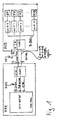
- Fig. 1 illustrates individual functional elements, which for the Understanding the bus system described below helpful are.
- the processor core APX-KERN assigns a common bus R-BUS with data, address and control lines on.
- IAIBC In addition to the processor core APX-KERN, which for example is clocked at 200 MHz, located on the die or APX processor chip a IAIBC bus interface, in which ends the conventional bus R-BUS of the processor APX.
- the bus interface IAIBC which below for the simpler Distinctness as internal bus interface or internal Bus controller IAIBC is set in bidirectional Direction the signals from the conventional bus R-BUS on a bus, which subsequently for easier distinctness as an advanced interface bus AIB (Advanced Interface Bus) is called.
- the to be transmitted Data from or to another bus interface or Bus controller EAIBC which for purposes of distinctness as an external bus control device or bus interface EAIBC is called.
- the external bus interface EAIBC serves as an interface between the interface bus AIB and the other external interface devices IFO - IF15, which interfaces with external facilities are formed.
- This further bus interface EAIBC and the other external interface devices IFO - IF15 are located in turn on a chip or board as an external interface arrangement ASD.
- To the other external interface devices IFO - IF15 can be common facilities for example, a computer or external peripherals be connected in a manner known per se, to the central processor APX and its processor core APX-KERN to communicate. The communication takes place via the intermediate interface bus AIB with, for example 20 MHz instead.
- the bus interfaces IAIBC, EAIBC have equal access to the bus.
- About the three Control lines become read ready signal IAIBC-RTR the internal bus control device or bus interface IAIBC, a read-ready signal EAIBC-RTR of the external bus controller EAIBC or a control signal CTR transmitted.
- control signal CTR in particular the information or data via the interface bus AIB via the data lines be transmitted as payload (user data) or Control data or control words SW identified.
- control signal CTR signals whether via the data lines or the data bus DL currently actual payload or such payload announcing or requesting Control word SW are transmitted.
- the internal Bus controller IAIBC always on the interface bus AIB access when a falling clock edge of the bus clock CL is present.
- the external bus controller EAIBC may accordingly always access the interface bus AIB, when there is a rising clock edge of the bus clock CL.
- the state of the bus clock be used as a criterion, d. H. whether the clock signal is in low or high state.
- bus AIB For such an interface bus AIB is a simple bus protocol usable.
- the bus protocol can based on the following basic principles.
- the external bus controller EAIBC When read-ready signal IAIBC-RTR of the internal Bus controller IAIBC is in the "high” state and in this state "high” via the corresponding control line I-RTR transmitted to the external bus controller EAIBC becomes, the external bus controller EAIBC is characterized signals that the internal bus controller IAIBC for Receiving a control command is ready.
- This readiness signal IAIBC-RTR is issued by the internal bus controller IAIBC generated and at the first of the control lines I-RTR created.
- the control signal or read ready signal IAIBC-RTR is allowed by the internal bus controller IAIBC according to This embodiment always at the time of falling Edge of the clock CL of the interface bus AIB changed become. Alternatively, for example, would be according to another Bus protocol also allowed the change in the state "deep" of the clock CL may be made.
- This Read ready signal EAIBC-RTR is generated and at the second control line E-RTR of the interface bus AIB.
- This read-ready signal EAIBC-RTR serves to internal bus controller IAIBC to signal that the external bus controller EAIBC for receiving a control word or data is ready when the read ready signal EAIBC-RTR is in "high” state.
- This readiness signal EAIBC-RTR is allowed by the external bus controller EAIBC according to the preferred embodiment each together with the rising edge of the clock CL of the Interface bus AIB to be changed. Corresponding is Here, for example, alternatively permitted, changes this Signal during the state "high" of the clock CL make.
- the control command or the control signal CTR can be from both Bus controllers IAIBC, EAIBC via the corresponding third control line CTRL be sent. In normal condition the control signal is in the state "low".
- a control command CTR wants to send out, it sets the control signal CTR for a short time or in the long term in the state "high". To avoid a collision It also states that only the Bus controller IAIBC or EAIBC a control command CTR whose read ready signal IAIBC-RTR or EAIBC-RTR is in the "low” state.
- the timing to raise the state of the control signal CTR falls to avoid collisions e.g. with the time together, to which the corresponding bus control device IAIBC or EAIBC also the state of their read ready signal IAIBC-RTR or EAIBC-RTR may change.
- both transmit bus controllers IAIBC, EAIBC the control signal CTR and an associated one Control word SW in each case with a rising edge of the Clock CL off.
- the internal bus control device may IAIBC a control command CTR on a rising edge of the clock CL of the interface bus AIB.
- the external one Bus controller EAIBC is allowed a control command CTR together with the rising edge of the clock CL of the Create interface bus AIB.
- the corresponding read ready signal IAIBC-RTR or EAIBC-RTR remains in the "low” state, if after the control word SW or control command CTR data or other data to be transmitted. This can by increasing the state of the read ready signal IAIBC-RTR or EAIBC-RTR of the other bus control device EAIBC or IAIBC signals the end of the data transfer become.
- control word SW in particular the type of transfer, z. B. to a register, memory, according to DMA (Direct Memory Access), but also the direction, z. For example, whether to read or to write, and / or the number or address of the addressed External interface device IFO - IF15 announced become.
- DMA Direct Memory Access
- control word SW with the control line marked as such.
- This can then z. B. a read command from the receiving bus controller IAIBC, EAIBC ignored or delayed to itself a control command sell with higher priority.
- Particularly preferred embodiments thus have one Interface bus AIB with three or four control lines.
- these are for transmission the read ready signals IAIBC-RTR, EAIBC-RTR and of the clock CL of the interface bus AIB, wherein the transmission of the control signals CTR completely omitted or also via a correspondingly coded control word SW on the Data lines takes place.
- four Control lines are used for the transmission of the control signal CTR and the transmission of the clock CL of the interface bus AIB each provided their own control lines.
- the Clock signal CL thus has the function of a control signal.
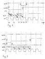
- the state diagram shown in FIG. 2 is exemplary in the case of direct memory access according to DMA (Direct Memory Access) from one of the external interface devices IF0 to a memory in the range of the central processor APX.
- DMA Direct Memory Access
- each of the external interface devices IF0-IF15 a DMA request line on.
- the external interface device IFO sends a DMA request to the external bus controller EAIBC via appropriate direct connection lines or a regular or conventional bus R-BUS.
- the transfer of the request via the interface bus AIB then takes place according to the Scheme described below.
- the external interface device IFO wants to write data to the central storage, sends the External interface device IFO to a DMA request the external bus controller EAIBC.
- the external bus controller EAIBC decides the external bus control device, which meets the requirements highest priority.
- the other requirements are in one Queue queued or rejected.
- the external one Bus controller IAIBC encodes the number or address of the External interface device IF0 and transmits them in a control word SW via the interface bus AIB. The transfer takes place preferably in accordance with the above-described Requirements.
- the internal bus controller AIBC samples the received one Control word SW after the number of the external interface device IFO and checks if there is a reading or write request. If the request is in Form of a control word SW or control command as one Write request is coded, is waiting for, preferably 32 data bits are available to this processor core APX-KERN and at its input port or the R-BUS to apply. Thereafter, the internal bus controller sends IAIBC issues a DMA request and returns it via the interface bus AIB received data on the regular bus R-BUS to the processor core APX-KERN, in case the bus for it from the processor core was released.
- the top line indicates the reception read ready signal IABC-RTR of the internal Control device IAIBC shown.
- the second line is the readiness read / write signal EAIBC-RTR of the external Control device EAIBC shown.
- the control signal CTR shown which on a the control lines CTRL transmitted in bidirectional direction becomes.
- the flow of data especially data packets preferably 16-bit data information per data packet, and the flow of control words SW shown. among them is shown in the last line of the bus clock CL of the Interface bus AIB, by one of the participating institutions or generated externally and to the bus controllers AIBC, EAIBC is created.
- the illustrated signals IAIBC-RTR, EAIBC-RTR, CTR and CL are each in the State "high” h or "deep” 1, these states in after shown on the right side in chronological order can.
- Fig. 2 illustrates the timing signal flow when an external interface device IFO a data packet to the processor core APX-KERN sends.
- the control signal is in the state "low” and a data transfer takes place not happening.
- At a first time t1 is due to the external Bus interface EAIBC to a DMA write request.
- the external bus controller EAIBC the state of their Read ready signal EAIBC-RTR to "low” (1) - (5).
- the external bus controller EAIBC can transfer also slow down or interrupt when the internal Bus controller IAIBC at a later date t4 is not in a ready to receive state, d.
- H. read ready signal IAIBC-RTR of the internal Bus controller in IAIBC are in the "low” state should (4) until a readiness to receive the internal Control IAIBC by corresponding increase of their read-ready signal IAIBC-RTR at a later Time t6 is signaled (6).
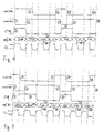
- Fig. 3 shows the case that e.g. the first external interface device IFO sends two or more data packets and not by a delay on the central Bus R-BUS to processor core APX-KERN or other transmissions, for example, from or to other external interface devices IF1 - IF15, delayed or interrupted becomes.
- the read-ready signal is located IAIBC-RTR of the internal bus controller IAIBC consistently in the "high" state.
- the external bus controller EAIBC can do this when creating a transfer request from the external interface device IF0 at the next rising change of the clock CL in the state "high" readiness to read, d. H. the read-ready signal state go "deep" (1).
- control signal CTR in the state offset "high" (2), (3).
- the Control word SW on the data lines DL of the interface bus AIB set. Since the control word SW at the same time an address information contains or may contain serve the data lines DL at the same time as address lines.
- Fig. 4 illustrates the situation in which the external interface device IFO sends data, but through the internal bus controller IAIBC is interrupted.
- EAIBC becomes with the rising clock edge in the presence of to be transmitted Data in the external bus controller EAIBC initiated by this the transfer.
- This is at increasing Clock edge of the clock CL the read-ready signal EAIBC RTR of the external bus controller EAIBC in the state set "low” (1), a control signal CTR via the control line CTRL is activated for one clock period (2) - (3) and on first control word SW on the interface bus AIB or on whose at least one data line is set.
- Preference is given here an embodiment with an interface bus, which 16 data lines DL, so that per clock period, such as this is shown, one control word SW or one complete Data packet DP can be transmitted.
- the external bus controller EAIBC After transmission of the control word SW and two data packets DP detects the external bus controller EAIBC, that the internal bus controller IAIBC half a clock period of the clock CL before the read ready signal IAIBC-RTR into the state "deep" has set (4), thus not ready to receive is.
- the external bus controller EAIBC can then interrupt the transmission of further data or delay.
- the external bus control device goes EAIBC in the state "high” (5) to the internal Bus controller IAIBC ready to signal readiness.
- the internal bus controller IAIBC with the next rising clock edge of the clock CL in turn Activate control signal CTR for one clock period (6) and at the same time a control word SW on the data lines DL of Set interface bus AIB.
- the internal bus controller IAIBC sets data packets DP on the data lines DL.
- the control word SW and the data packets DP are then from the external bus controller EAIBC received, evaluated and the corresponding external interface devices supplied (7).
- the internal bus controller IAIBC sets its read ready signal IAIBC-RTR again in the state "high” and is ready to receive (8). With the next rising Cycle edge, the external bus controller EAIBC thus switch back to the transmission state (9) - (10), as is appropriate the initial transmission of the first control word and the first data packets were described.
- Fig. 5 illustrates the state flow when e.g. the external interface device IFO requests a DMA read. In the example shown, it is assumed that is about a fast and not delayed by the processor APX or interrupted transmission.
- the external bus interface EAIBC has to decide which Requirement has the highest priority. All others will be in queued or rejected a queue.
- the number or address of the external interface device IFO is encoded and together with the DMA request in a control word SW transmitted via the interface bus AIB (1) - (2). If this request is decoded as a read request, the internal bus controller IAIBC will be like one of the internal bus controllers DMA units respond and send a DMA request via the regular bus R-BUS to the processor core APX-KERN. With In a corresponding allocation, it puts the 32-bit data to the regular bus R-BUS between processor core APX-KERN and internal Bus controller IAIBC and clears the request lines.
- the internal bus controller IAIBC sends these Data over the interface bus AIB to the external bus controller EAIBC.
- four data packets DP are transmitted, wherein the first 16-bit data of the 32-bit data in first a data packet based on "high" state and then in one transmit second data packet based on the low state and then transmit the second 16-bit data accordingly become (5).
- the external bus controller EAIBC has completely received the 32-bit data, with the first If necessary, data bits are buffered and sent this to the requesting external interface device IFO. With the caching of the received data deletes the external interface IF0 their request lines and the transfer is terminated.
- Fig. 5 In the state diagram of Fig. 5 is a corresponding sequence shown.
- EAIBC Based on reading readiness of the two Bus controllers IAIBC, EAIBC switches the external Bus controller EAIBC after the arrival of a DMA read request at the next rising clock edge of one of the external interface devices in the non-read-ready state (1).
- the external submits Bus controller EAIBC the control signal on the control line CTR for one clock period in the state "high" (2). additionally becomes from the external bus controller EAIBC a corresponding request generated and as the control word SW via the data lines DL transferred to the interface bus AIB.
- the internal bus controller IAIBC receives this Control word SW and switches in the ideal case according to Forwarding to the processor core APX-KERN, already half Clock period later with the next falling clock edge of the clock CL in the non-read-ready state (3). thereupon turns on the external bus controller EAIBC preferably already the next rising clock edge of Clock CL again in the state of readiness to receive and signals this by raising the read ready signal EAIBC-RTR (4).
- the internal bus controller IAIBC can now in the meantime on the regular bus R-BUS from the processor core APX-KERN, received data with the next clocks of the clock CL on the data lines DL of Create interface bus AIB.
- the waiting for data packets External bus controller receives these data packets DL from Interface bus AIB and forwards these to the requesting external interface device IFO (5).
- the receive memory of the external bus controller EAIBC When the receive memory of the external bus controller EAIBC is full signals the external bus controller EAIBC this the internal bus controller IAIBC by the Downsetting the ready-to-receive signal EAIBC-RTR with the next rising clock edge of the clock CL (6).
- the internal Bus controller IAIBC then stops sending the data up to a readiness to receive the external Bus controller EAIBC.
- closes the internal bus control device IAIBC also leads and puts himself in the state for receiving new commands by incrementing the Read ready signal IAIBC-RTR (7).
- the external bus controller EAIBC holds her readiness signal EAIBC-RTR while in this state (8), at least for one clock cycle of the clock CL in the low state until the memory free again is or, as in the illustrated embodiment, a new DMA request by the external interface device IFO or other external interface device IF1 - IF15 arrives at her. Then, in turn, one Control command CTR is set to the control line CTRL (9) and a control word SW to the data lines DL of the interface bus AIB created (10).
- Fig. 6 describes the case where the external interface device IF0 requests a single data transfer, the however, by the usual bus R-BUS between the internal Bus controller IAIBC and the processor core APX-KERN delayed is performed when the processor core APX-KERN the can not provide requested data fast enough.
- the starting point is a readiness readiness of both bus control devices IAIBC, EAIBC.
- EAIBC After receiving the data request from the external interface IF0 changes the external Bus controller EAIBC read readiness signal EAIBC-RTR in the non-ready state (1) to send at the same time a control signal CTR via the control line (2) and sends a command or control word SW over the data lines DL to the internal bus controller IAIBC. This happens, as in the previous embodiments, together with the rising edge of the clock CL.
- a blockage of the interface bus AIB is thus reduced to the time actually spent on the Transmission of control words SW and data packets DP required is.
- the internal bus controller IAIBC After the existence of the data to be transmitted or Data packets DP and switch to non-read-ready state sends the internal bus controller IAIBC the data as data packets DP via the data lines DL, where according to the exemplary format in the next bars again one or two 16-bit data packets are transmitted.
- the external bus controller EAIBC can transfer slow down or interrupt, if their receive memory is full by the read ready signal EAIBC-RTR for transmitting a new control word SW and sending a Control signal or control command CTR via the control line CTRL (8) for one clock cycle in the state "deep" becomes (7).
- the internal bus controller IAIBC after transmission of data packets DP (5) in the meantime changed to reading readiness state (6) is.
- This transmission of another control word SW by the external bus controller is thus either by going over the internal bus controller IAIBC in FIG the readiness to read (6) or a lack of ability of the external Bus controller EAIBC for receiving further data triggered.
- Another reason for sending out another Control word SW can also consist in that the external Bus controller EAIBC, for example, another, under Circumstances more urgent DMA request with the control word SW via the interface bus AIB in the direction of the processor core APX-KERN has to send.
- Embodiment remains the external bus control device EAIBC after sending the DMA request or the corresponding one Control word SW (7, 8) immediately read-ready (10), to receive the urgently awaited data DP promptly and after the end of the transmission via the interface bus AIB (11) to the requesting external interface device IFO to be able to forward (12).
- Fig. 7 shows an embodiment of the procedure for the Case that an external interface IF0 requests data, being a fast transfer through the processor core APX-KERN is interrupted.
- the external bus controller EAIBC sends the external bus controller EAIBC in already described Way a first control word SW over the Interface bus AIB to the internal bus controller IAIBC.
- the internal bus controller IAIBC decodes this control word and calls from the processor core APX-KERN over the conventional Bus R-BUS on the part of the external interface device IF0 requested data.
- IAIBC already after one half clock announces the internal bus controller IAIBC by lowering the read-ready signal IAIBC-RTR, that the data is ready and put it on the interface bus AIB wants to access (1, 2, 3).
- the external bus controller EAIBC interrupts the sending of further data or control words and already goes into the Read Standby state after one clock cycle (4).
- the external bus controller now expects the requested Data on the data lines DL. She gets from the internal bus controller IAIBC a higher priority Control Word SW * transmitted over the data lines DL (5). According to the selected data format then follow data packets (6) via the data lines DL of the interface bus AIB, which belong directly to the higher priority control word SW *.
- the internal bus control device goes again in read-ready state (7).
- the external one Bus controller EAIBC transmits the received data to an external register or the corresponding in the control word SW * specified external interface device IFO and call the bus again (8, 9). Then the external sends Controller EAIBC the original DMA request, which of the internal bus controller IAIBC was ignored again on the interface bus AIB and then receives the requested data in already above described manner (8-14).
- Fig. 8 shows an exemplary state diagram for the case in that the processor APX inputs data from its register external register writes.
- the external interfaces IFO - IF15 are controlled by a set of registers called as external module registers ext IF 0, ..., ext IF 15 are designated and between the external bus controller EAIBC and the external interface devices IF 0 - IF 15 connected are.
- external module registers by means of an internal standard bus R-BUS accessed.
- interface bus AIB which between the processor APX and the external interface devices IF 0 - IF 15 is switched, corresponding requests of the Processor APX or the processor core APX-KERN, through the internal and the external bus controller IAIBC, EAIBC for the transmission via the intermediate interface bus AIB translated accordingly.
- the external bus controller EAIBC performs a back translation in the usual format through and transmits the back translated control signals and data then to the requested external module registers ext IF 0 - ext IF 15.
- the transmission via the interface bus AIB takes place in case of doubt, time multiplexed.
- the number or address of the external to be addressed Module register ext IF 0 - ext IF 15 is controlled by the internal Bus controller IAIBC encoded and in a control word SW via the interface bus AIB, possibly together with Information about the data format to the external bus controller Transferred EAIBC. This then performs the back translation by.
- To create the control word SW check the internal bus controller IAIBC over the regular Bus R-BUS from the processor core APX-KERN received control signals, Address and data information regarding the to be implemented Information, in particular the register address and regarding the information, whether it is a reading or reading Write is.
- the transmission of an original word with a length of 32 bits is used for transmission over the Interface bus AIB in the present case to two control words and / or data packets each with 16-bit length and implemented by the external bus controller EAIBC accordingly as a word reconstructed with a length of 32-bit and then to the external module registers ext IF 0 - ext IF 15 resent.
- Fig. 8 is an illustration of a writing operation of Processor APX to a selected one of the external module registers ext IF 0 - ext IF 15 from a state with read-ready signals high IAIBC-RTR, EAIBC-RTR, a subscribtion Control signal CTR and a continuous bus clock CL of the Interface bus AIB off.
- a first step sets the internal bus controller IAIBC after receiving a Write request from the processor APX read readiness signal IAIBC-RTR in the state "deep", namely at the next falling edge of the clock CL (1).
- the external bus controller EAIBC receives at this procedure first the control word SW, the external Bus controller EAIBC on the over this clock period high-level control signal CTR (2) detects that the data is on the data lines DL of the interface bus AIB a control word SW represent. After an analysis regarding the address and the type of control command, in this case a write command, receives the external bus controller EAIBC at the next clocks the data packets DP. Since the control signal CTR with the end of the transmission of the control word SW back into the State has been "deep", recognizes the external bus controller EAIBC that is on the data lines DL of the interface bus AIB received information Data is related to the external interface devices IFO - IF15. Because the external Bus controller EAIBC previously received the control word SW and decodes them in parallel with the transmission of the received data to the appropriate control lines the associated address information and control information, so the forwarded data only from the desired external interface device IF0 be taken into account.
- the external bus control device EAIBC due to a full receive or output memory unable to receive more data.
- sets the external bus controller EAIBC their readiness signal EAIBC-RTR meanwhile, in the present case over a cycle time, into the state "low” (5, 6).
- the external sets Bus controller EAIBC the read ready signal EAIBC-RTR back to the state "high” after being due to a Emptying the memory again capable of receiving new data is (7).
- the duration of the state "low” (6) is thereby a multiple of the clock cycle of the clock CL of the interface bus AIB to frequencies higher than that of the clock CL of the interface bus AIB.
- Fig. 9 shows a state diagram in the case of a read request of the processor APX to one of the external interface devices IFO - IF15 or the module register assigned to it ext IF 0 - ext IF 15.
- the corresponding Register address which the internal bus controller IAIBC via the regular bus R-BUS receives, along with others Information, in particular the signaling of a read request, encoded in a control word SW and over the interface bus AIB transferred to the external bus controller EAIBC. This decodes the received control word SW and forwards this along with the read request to the appropriate one External interface device IF0 - IF15 or the this assigned external module register on.
- the external interface device IFO - IF15 or its external module register Ext IF 0 - ext IF 15 then sends the contents of the addressed register to the external bus interface device EAIBC.
- the control signal CTR is back to the state set to "low", whereupon the internal bus controller IAIBC to receive the data or, if necessary, higher priority Control words and data from the external bus controller EAIBC is waiting (4).
- the external bus control device EAIBC receive and decode the control word SW the external interface devices IF0 - IF15 forwarded has, sets the addressed external interface device IFO the data of its external module register ext IF 0 to the data lines to the external bus controller EAIBC on. This receives the data accordingly and sets this in a format suitable for the interface bus AIB.
- the external bus control EAIBC sets her Read ready signal EAIBC-RTR with the next rising one Edge of the clock CL in the state "deep” (4) and places, as long as data is to be transmitted, corresponding data or data packets over the next bars away with the rising one Clock edge of the clock CL to the data lines DL of the interface bus AIB (5).
- the external bus controller EAIBC After the transfer of Last requested data packets DP goes to the external bus controller EAIBC returns to readiness to read (6).
- the internal bus controller IAIBC receives the applied to the data lines DL of the interface bus AIB Data or data packets DP and puts them in the appropriate Format for the regular bus R-BUS to the processor core APX-CORE.
- Fig. 10 illustrates a simple embodiment of a Bus controller IAIBC or EAIBC dar.
- the bus control device It can be very simple and essentially exists from multiplexers / demultiplexers MX, which is an adaptation the data width of a regular bus R-BUS to the Data width of the interface bus AIB.
- the bus controllers IAIBC, EAIBC have a state machine Z, whose state can be queried via a state register ZR and is settable. Unless the third control line accepts a clock function, an external clock CL as Clock of the interface bus AIB for controlling the individual Components created.
- the state machine Z also switches optionally either incoming address data and status information or actual data to be transmitted to the data lines DL of the interface bus AIB.
- the state machine Z has at least three outputs through which the control information to the communicating other bus controller be transmitted.
- the status register ZR has control lines WR, RE for the exchange of in particular writing and Read requests with the APX-KERN processor.
- An advantageous use of such a circuit arrangement with such bus control devices IAIBC, EAIBC is particular possible to use a microprocessor APX with a Interface chip ASD to connect.
- Advantageous is the application the interface bus AIB and the bus controllers IAIBC, EAIBC especially whenever it comes to it goes, a multimaster-enabled bus with low controller to realize overhead and few control lines.
- the bus controllers IAIBC, EAIBC preferably have a comparator V on which the priority before received read or write requests with priority currently received read or write requests and depending on the comparison, an interruption of the current data exchange permits or does not allow.
- V the bus controllers IAIBC, EAIBC a detector (D), which a data congestion on wechingn Data lines to external interface devices (IF0 - IF15) or to the processor core APX-KERN, ie further receiving facilities, recognizes and transmits data or the data exchange during this time of the data jam delayed.
- bus controller IAIBC, EAIBC and Interface bus AIB serve only to distinguish the individual components compared to the other described Components, in particular with respect to the usual buses R-BUS, between which the interface bus AIB with the Bus controllers IAIBC, EAIBC is interposed.
- General can also be controlled by IAIBC, EAIBC and be spoken to a bus AIB.
- the number is the data lines DL is not limited to the number 16. A larger or smaller number of data lines DL is also feasible.
- a regular bus R-BUS opposite the interface bus AIB be according to cache and multiplexer in the Bus controllers IAIBC, EAIBC provided.
- the interface bus thus advantageously has Bus controllers (IAIBC, EAIBC) operating between two Buses or bus connections are switched.
- the buses or Bus connections like common buses, are each separate Data, address and control lines.
Abstract
Description
Die Erfindung bezieht sich auf ein Bussystem mit einem Bus gemäß
den oberbegrifflichen Merkmalen des Patentanspruchs 1, einen
damit gebildeten Schnittstellenbus sowie ein Steuerverfahren
für einen solchen Bus.The invention relates to a bus system with a bus according to
the preamble features of
Zur Übertragung von Daten zwischen zwei Einrichtungen dienen üblicherweise Bussysteme mit einem Bus, welcher Busschnittstellen zum Anschluss der Daten übertragenden Einrichtungen aufweist. Bei den meisten Bussystemen gibt es entweder eine starre Vorgabe, welche der angeschlossenen Einrichtungen als steuernde Buseinrichtung (master) und welche der Einrichtungen als dienende Buseinrichtung (slave) verwendet wird. Häufig verwendet wird auch eine spezielle aufwendige Steuerung mit sogenannten memory/DMA-Controllern (DMA: direct memory access).To transfer data between two institutions Usually bus systems with a bus, which bus interfaces for connecting the data transmitting devices having. For most bus systems, there is either one rigid specification of which of the connected facilities as controlling bus device (master) and which of the devices is used as a serving bus device (slave). Often Also used is a special complex control with so-called memory / DMA controllers (DMA: direct memory access).
In Computern werden Busse zur Übertragung von Daten zwischen verschiedenen Einrichtungen verwendet, wobei die Steuerung des Datenbusses von einer zentralen Recheneinrichtung (CPU) übernommen wird. Zum Steuern weist die zentrale Recheneinrichtung neben dem Datenbus zur Datenübertragung einen Adressbus zur Übertragung der Adresse derjenigen Einrichtung des Computers auf, zu welcher bzw. von welcher aus eine Datenübertragung über den Datenbus stattfinden soll. Außerdem gibt es Steuerleitungen, welche von der zentralen Recheneinrichtung zu den einzelnen Einrichtungen führen, um zu signalisieren, ob die entsprechende Einrichtung Daten über den Datenbus empfangen oder Daten über den Datenbus senden soll. Außerdem dienen die Steuerleitungen bzw. ein Steuerbus dazu, den Zeitpunkt der Übertragung über den Datenbus zu bestimmen. Es handelt sich somit um eine zentrale Steuerung der Datenübertragung über den Datenbus, bei welcher die zentrale Steuereinrichtung die Freigabe des Datenbusses für die einzelnen angeschlossenen Einrichtungen bewirkt.In computers, buses are used to transfer data between various devices used, the control of the Data bus taken from a central computer (CPU) becomes. For controlling, the central computing device in addition to the data bus for data transmission an address bus to Transmission of the address of the device of the computer on, from which or from which a data transmission via the data bus is to take place. There are also control cables, which from the central computing device to the individual Facilities lead to signal if the appropriate Device receiving or receiving data via the data bus To send data over the data bus. In addition, the control lines serve or a tax bus to, the date of transfer to be determined via the data bus. It is thus a central control of data transmission via the data bus, in which the central control device the release the data bus for each connected device causes.
Allgemein bekannt ist auch das Prinzip des sogenannten Handshaking, bei dem die einzelnen an einen Datenbus angeschlossenen Einrichtungen untereinander kommunizieren, wobei ebenfalls ein zentraler Prozessor eine Koordinierung des Datenzugriffs organisiert. Neben dem Datenbus zur Übertragung von Daten zwischen den einzelnen Einrichtungen gibt es zumindest drei Leitungen, welche als Steuerleitungen verwendet werden. Auf diesen werden üblicherweise sogenannte strobe-, acknowledge- bzw. interrupt-Signale übertragen. Aus Sicht des Prozessors erfolgt eine Dateneingabe zu diesem über den Datenbus hinweg dadurch, dass ein angeschlossenes Peripheriegerät die zu übertragenden Daten an den Leitungen des Datenbusses anlegt und mittels eines strobe-Signals dem Prozessor signalisiert, dass Daten zum Übertragen bereitliegen. Das interrupt-Signal auf der interrupt-Steuerleitung dient dazu, dem Peripheriegerät zu signalisieren, ob ein Eingangspuffer der empfangenden Einrichtung leer ist und somit weitere Daten an die Datenleitungen angelegt werden können. Sobald der Prozessor das Abholen der Daten aus dem Eingangspuffer veranlasst hat, wird das interrupt-Signal zurückgenommen und dem angeschlossenen Peripheriegerät somit signalisiert, dass eine erneute Datenübertragung durchgeführt werden kann.Also well-known is the principle of so-called handshaking, where the individual connected to a data bus Facilities communicate with each other, as well a central processor coordinating the data access organized. In addition to the data bus for transferring data between The individual facilities have at least three lines, which are used as control lines. On this are usually called strobe, acknowledge or transmit interrupt signals. From the perspective of the processor a data entry to this across the data bus thereby, that a connected peripheral device to be transmitted Data on the lines of the data bus creates and by means of a strobe signal to the processor that signals data to Transfer ready. The interrupt signal on the interrupt control line serves to signal the peripheral device whether an input buffer of the receiving device is empty and thus created more data to the data lines can be. Once the processor picking up the data from the input buffer, the interrupt signal withdrawn and the connected peripheral device thus signaling that a renewed data transmission is performed can be.
Im Fall einer Datenausgabe von der Einrichtung mit dem Prozessor zu dem Peripheriegerät legt der Prozessor die Daten an den Datenleitungen des Datenbusses an und löst einen Schreibimpuls aus. Das Peripheriegerät quittiert das Abholen der Daten mit dem acknowledge-Signal, woraufhin durch das Rücksetzen des interrupt-Signals dem Prozessor signalisiert wird, dass der Datenbus für eine neue Übertragung bereitsteht. Auch bei dieser Anordnung erfolgt die Zuweisung des Datenbusses zur Übertragung von Daten zu den einzelnen angeschlossenen Einrichtungen somit von dem zentralen Prozessor aus.In the case of a data output from the device to the processor to the peripheral device, the processor attaches the data to the Data lines of the data bus and triggers a write pulse out. The peripheral device acknowledges the retrieval of the data the acknowledge signal, whereupon by resetting the interrupt signal the processor is signaled that the data bus ready for a new transfer. Also with this Arrangement takes place the assignment of the data bus for transmission data about each connected device thus from the central processor.
Für die Verarbeitung von interrupts sind allgemein softwareund hardware-interrupts bekannt. Hardware-interrupts werden dabei an interrupt-Steuereinrichtungen gerichtet, welche auch eine Priorisierung verschiedener parallel zueinander eingehender Anfragen auf Zuteilung des Datenbusses ermöglichen.For the processing of interrupts are generally software and hardware interrupts known. Hardware interrupts directed to interrupt control devices, which also a prioritization of various incoming parallel Allow requests for allocation of the data bus.
Übliche Bussysteme weisen somit einen Datenbus, einen Adressbus und einen Steuerbus bzw. entsprechende Signalisierungsund Steuerleitungen auf.Conventional bus systems thus have a data bus, an address bus and a control bus or corresponding signaling and Control cables on.
Heutige Prozessorchips für eine digitale Signalverarbeitung bzw. deren zentrale Steuereinrichtungen sind üblicherweise mit einer großen Anzahl von Direktzugriffs-Speicherplätzen (RAM) auf dem Chip bzw. Die ausgebildet, so dass sie in einer möglichst neuartigen und teuren Verfahrensweise gefertigt werden müssen. Aus einer Vielzahl von Gründen ist es nicht sinnvoll, auf einem solchen Prozessordie eine Vielzahl von Schnittstellen zu integrieren. Für die Bereitstellung der Schnittstellen ist jedoch keine derart hochentwickelte Technologie erforderlich, wie für die Fertigung der Prozessordies. Auch mit Blick auf die Variabilität der Anforderungen bezüglich der speziellen Schnittstellen ist es sinnvoller, eine getrennte Schnittstelle bereitzustellen. Weitere Gründe liegen in Fertigungsparametern und Materialparametern, z. B. der Spannungsfestigkeit. Um einen Prozessorkern der Steuereinrichtung auf einem Prozessordie mit einer Schnittstelleneinrichtung, insbesondere einem Schnittstellenchip zu verbinden, wird ein Bus benötigt, der schnell ist, mit wenigen Leitungen auskommt, wenige o-verheads (Überlast) hat und verschiedene Arten von Übertragungen ermöglicht, beispielsweise Register und Speicher einzeln adressiert oder einen direkten Speicherzugriff (DMA) ermöglicht.Today's processor chips for digital signal processing or their central control devices are usually with a large number of random access memory (RAM) slots on the chip or the formed, so that they in one possible new and expensive procedure to be manufactured have to. For a variety of reasons, it does not make sense on such a processor, a variety of interfaces to integrate. For the provision of the interfaces however, no such sophisticated technology is required as for the production of the processor files. Also with a view on the variability of the requirements for the specific Interfaces, it makes more sense, a separate interface provide. Further reasons lie in production parameters and material parameters, e.g. B. the dielectric strength. To a processor core of the control device on a Processor with an interface device, in particular to connect an interface chip, a bus is needed fast, with few leads, few o-leads (Overload) has and different types of transfers allows, for example, registers and memory individually addressed or direct memory access (DMA) allows.
Die Aufgabe der Erfindung besteht darin, ein Bussystem mit einem Bus bereitzustellen, welcher insbesondere als Schnittstelle zwischen einem Prozessorkern mit üblichem Busanschluss und Schnittstelleneinrichtungen zu weiteren Systemeinrichtungen und Peripheriegeräten ausgebildet ist.The object of the invention is a bus system with a Bus provide, which in particular as an interface between a processor core with standard bus connection and Interface devices to other system devices and peripheral devices is formed.
Diese Aufgabe wird durch einen Systembus mit den Merkmalen des
Patentanspruchs 1 gelöst. Vorteilhafte Lösungen bieten auch
ein Schnittstellenbus für die Verbindung zwischen einem Prozessorkern
und Schnittstelleneinrichtungen zu externen Einrichtungen
und Geräten mit den Merkmalen des Patentanspruchs
17 bzw. ein Steuerverfahren zum Betreiben derartiger Busse mit
den Merkmalen des Patentanspruchs 18.This task is performed by a system bus with the features of
Vorteilhafte Ausgestaltungen sind Gegenstand abhängiger Ansprüche.Advantageous embodiments are the subject of dependent claims.
Nachfolgend wird ein Ausführungsbeispiel anhand der Zeichnung näher erläutert. Es zeigen:
- Fig. 1
- eine Schaltungsanordnung eines Bussystems;
- Fig. 2
- ein Zustandsdiagramm verschiedener Signale auf den Leitungen eines solchen 16-Bit-Bussystems für den Fall, dass eine externe Schnittstelle ein 32-Bit-Datenpaket sendet;
- Fig. 3
- ein solches Zustandsdiagramm für den Fall, dass die externe Schnittstelle weitere Daten sendet;
- Fig. 4
- ein Zustandsdiagramm für den Fall, dass die externe Schnittstelle Daten sendet und dabei durch die andere Schnittstelle unterbrochen wird;
- Fig. 5
- ein Zustandsdiagramm für den Fall, dass die externe Schnittstelle Daten anfordert;
- Fig. 6
- ein Zustandsdiagramm für den Fall, dass die externe Schnittstelle Daten anfordert, wobei eine Verlangsamung durch den regulären Bus zwischen der anderen Schnittstelle und dem Prozessorkern erfolgt;
- Fig. 7
- ein Zustandsdiagramm für den Fall, dass die externe Schnittstelle Daten anfordert und nicht unterbrochen wird;
- Fig. 8
- ein Zustandsdiagramm für den Fall, dass die interne bzw. andere Busschnittstelle Daten in einen Bereich für die externe Schnittstelle schreibt;
- Fig. 9
- ein Zustandsdiagramm für den Fall, dass die interne Busschnittstelle aus einem externen Registerbereich liest; und
- Fig. 10
- schematisch eine der Bussteuereinrichtung zur Umsetzung von Adressen eines Adressbusses zwischen einem Systembus und dem Schnittstellenbus.
- Fig. 1
- a circuit arrangement of a bus system;
- Fig. 2
- a state diagram of various signals on the lines of such a 16-bit bus system in the event that an external interface sends a 32-bit data packet;
- Fig. 3
- such a state diagram in the event that the external interface sends more data;
- Fig. 4
- a state diagram in the event that the external interface sends data while being interrupted by the other interface;
- Fig. 5
- a state diagram in the event that the external interface requests data;
- Fig. 6
- a state diagram in the event that the external interface requests data, with a slowdown by the regular bus between the other interface and the processor core;
- Fig. 7
- a state diagram in the event that the external interface requests data and is not interrupted;
- Fig. 8
- a state diagram in the event that the internal or other bus interface writes data in an area for the external interface;
- Fig. 9
- a state diagram in the event that the internal bus interface reads from an external register area; and
- Fig. 10
- schematically one of the bus control device for converting addresses of an address bus between a system bus and the interface bus.
Fig. 1 stellt einzelne Funktionselemente dar, welche für das Verständnis des nachfolgend beschriebenen Bussystems hilfreich sind. Eine Umsetzung auf andere Bussysteme, insbesondere eine Verwendung von mehr oder weniger Daten- und Steuerleitungen, ist durch entsprechende Umgestaltung möglich.Fig. 1 illustrates individual functional elements, which for the Understanding the bus system described below helpful are. An implementation on other bus systems, in particular one Using more or less data and control lines, is possible through appropriate redesign.
Beim dargestellten Ausführungsbeispiel soll eine Datenübertragung zwischen einem Prozessorkern APX-KERN einer Prozessoreinrichtung APX zu einer Vielzahl verschiedener Schnittstelleneinrichtungen IF0, IF1, IF2, ... IF15 durchgeführt werden. In üblicher Art und Weise weist der Prozessorkern APX-KERN dazu einen üblichen Bus R-BUS mit Daten-, Adress- und Steuerleitungen auf.In the illustrated embodiment, a data transmission between a processor core APX-KERN of a processor device APX to a variety of different interface devices IF0, IF1, IF2, ... IF15. In the usual way, the processor core APX-KERN assigns a common bus R-BUS with data, address and control lines on.
Zusätzlich zu dem Prozessorkern APX-KERN, welcher beispielsweise mit 200 MHz getaktet wird, befindet sich auf dem Die oder Chip des Prozessors APX eine Busschnittstelle IAIBC, in welcher der herkömmliche Bus R-BUS des Prozessors APX endet. Die Busschnittstelle IAIBC, welche nachfolgend zur einfacheren Unterscheidbarkeit als interne Busschnittstelle bzw. interne Bussteuereinrichtung IAIBC bezeichnet wird, setzt in bidirektionaler Richtung die Signale von dem herkömmlichen Bus R-BUS auf einen Bus um, der nachfolgend zur einfacheren Unterscheidbarkeit als weiterentwickelter Schnittstellenbus AIB (Advanced Interface Bus) bezeichnet wird.In addition to the processor core APX-KERN, which for example is clocked at 200 MHz, located on the die or APX processor chip a IAIBC bus interface, in which ends the conventional bus R-BUS of the processor APX. The bus interface IAIBC, which below for the simpler Distinctness as internal bus interface or internal Bus controller IAIBC is set in bidirectional Direction the signals from the conventional bus R-BUS on a bus, which subsequently for easier distinctness as an advanced interface bus AIB (Advanced Interface Bus) is called.
Über den Schnittstellenbus AIB, der eine möglichst geringe Anzahl von Steuerleitungen aufweist, werden die zu übertragenden Daten von bzw. zu einer weiteren Busschnittstelle bzw. Bussteuereinrichtung EAIBC geleitet, welche zu Zwecken der Unterscheidbarkeit als externe Bussteuereinrichtung bzw. Busschnittstelle EAIBC bezeichnet wird. Die externe Busschnittstelle EAIBC dient als Schnittstelle zwischen dem Schnittstellenbus AIB und den weiteren Extern-Schnittstelleneinrichtungen IFO - IF15, die als Schnittstellen zu externen Einrichtungen ausgebildet sind. Diese weitere Busschnittstelle EAIBC und die weiteren Extern-Schnittstelleneinrichtungen IFO - IF15 befinden sich wiederum auf einem Chip oder einer Platine als Extern-Schnittstellenanordnung ASD. An die weiteren Extern-Schnittstelleneinrichtungen IFO - IF15 können übliche Einrichtungen beispielsweise eines Computers oder externe Peripheriegeräte in für sich bekannter Art und Weise angeschlossen werden, um mit dem zentralen Prozessor APX und dessen Prozessorkern APX-KERN zu kommunizieren. Die Kommunikation findet dabei über den zwischengeschalteten Schnittstellenbus AIB mit beispielsweise 20 MHz statt.Via the interface bus AIB, the smallest possible number of control lines, the to be transmitted Data from or to another bus interface or Bus controller EAIBC, which for purposes of distinctness as an external bus control device or bus interface EAIBC is called. The external bus interface EAIBC serves as an interface between the interface bus AIB and the other external interface devices IFO - IF15, which interfaces with external facilities are formed. This further bus interface EAIBC and the other external interface devices IFO - IF15 are located in turn on a chip or board as an external interface arrangement ASD. To the other external interface devices IFO - IF15 can be common facilities for example, a computer or external peripherals be connected in a manner known per se, to the central processor APX and its processor core APX-KERN to communicate. The communication takes place via the intermediate interface bus AIB with, for example 20 MHz instead.
Dieser Schnittstellenbus AIB besteht beim dargestellten Beispiel aus n Datenleitungen mit z. B. n = 16 und zumindest drei Steuerleitungen I-RTR, E-RTR, CTRL. Während über die zumindest eine, vorzugsweise mehreren parallelen Datenleitungen Daten und Adressen übertragen werden, werden über die Steuerleitungen Steuersignale übertragen, welche eine Selbstarbitrierung (einen selbst zuteilenden Zugriff) auf den Schnittstellenbus AIB ermöglichen. Dabei können die Busschnittstellen IAIBC, EAIBC gleichberechtigt auf den Bus zugreifen. Über die drei Steuerleitungen werden ein Lesebereitschaftssignal IAIBC-RTR der internen Bussteuereinrichtung bzw. Busschnittstelle IAIBC, ein Lesebereitschaftssignal EAIBC-RTR der externen Bussteuereinrichtung EAIBC bzw. ein Steuersignal CTR übertragen.This interface bus AIB is in the illustrated example from n data lines with z. B. n = 16 and at least three Control cables I-RTR, E-RTR, CTRL. While about the least one, preferably a plurality of parallel data lines data and addresses are transmitted via the control lines Transmit control signals, which is a self-arbitration (a self-allocating access) to the interface bus Enable AIB. The bus interfaces IAIBC, EAIBC have equal access to the bus. About the three Control lines become read ready signal IAIBC-RTR the internal bus control device or bus interface IAIBC, a read-ready signal EAIBC-RTR of the external bus controller EAIBC or a control signal CTR transmitted.
Mit dem Steuersignal CTR werden insbesondere die Informationen bzw. Daten, die über den Schnittstellenbus AIB über die Datenleitungen übertragen werden, als payload (Nutzdaten) oder Steuerdaten bzw. Steuerworte SW identifiziert. Mit anderen Worten signalisiert das Steuersignal CTR, ob über die Datenleitungen bzw. den Datenbus DL momentan eigentliche Nutzdaten oder ein solche Nutzdaten ankündigendes oder anforderndes Steuerwort SW übertragen werden.With the control signal CTR in particular the information or data via the interface bus AIB via the data lines be transmitted as payload (user data) or Control data or control words SW identified. With others In words, the control signal CTR signals whether via the data lines or the data bus DL currently actual payload or such payload announcing or requesting Control word SW are transmitted.
Um die Zugriffszeitpunkte derart zu definieren, dass keine Kollision durch gleichzeitigen Zugriff beider Bussteuereinrichtungen IAIBC, EAIBC auf den Schnittstellenbus AIB erfolgt, wird durch die Bussteuereinrichtungen IAIBC, EAIBC der Bustakt CL verwendet. Zur Arbitrierung des Schnittstellenbusses AIB werden dabei die verschiedenen Taktflanken des Taktes CL verwendet.To define the access times such that no Collision due to simultaneous access of both bus control devices IAIBC, EAIBC takes place on the interface bus AIB, is the bus clock by the bus controllers IAIBC, EAIBC CL used. For arbitration of the interface bus AIB In this case, the different clock edges of the clock CL are used.
Bei der dargestellten Ausführungsform darf die interne Bussteuereinrichtung IAIBC immer dann auf den Schnittstellenbus AIB zugreifen, wenn eine fallende Taktflanke des Bustaktes CL vorliegt. Die externe Bussteuereinrichtung EAIBC darf entsprechend immer dann auf den Schnittstellenbus AIB zugreifen, wenn eine steigende Taktflanke des Bustaktes CL vorliegt. Alternativ oder zusätzlich kann auch der Zustand des Bustaktes als Kriterium herangezogen werden, d. h. ob das Taktsignal sich im niedrigen oder hohen Zustand befindet.In the illustrated embodiment, the internal Bus controller IAIBC always on the interface bus AIB access when a falling clock edge of the bus clock CL is present. The external bus controller EAIBC may accordingly always access the interface bus AIB, when there is a rising clock edge of the bus clock CL. alternative or additionally, the state of the bus clock be used as a criterion, d. H. whether the clock signal is in low or high state.
Für einen solchen Schnittstellenbus AIB ist ein einfaches Busprotokoll verwendbar. Beispielhaft kann das Busprotokoll auf den nachfolgenden Grundprinzipien beruhen.For such an interface bus AIB is a simple bus protocol usable. By way of example, the bus protocol can based on the following basic principles.
Wenn das Lesebereitschaftssignal IAIBC-RTR der internen Bussteuereinrichtung IAIBC sich im Zustand "hoch" befindet und in diesem Zustand "hoch" über die entsprechende Steuerleitung I-RTR zu der externen Bussteuereinrichtung EAIBC übertragen wird, wird der externen Bussteuereinrichtung EAIBC dadurch signalisiert, dass die interne Bussteuereinrichtung IAIBC zum Empfangen eines Steuerbefehls bereit ist. Dieses Lesebereitschaftssignal IAIBC-RTR wird durch die interne Bussteuereinrichtung IAIBC erzeugt und an der ersten der Steuerleitungen I-RTR angelegt. Das Steuersignal bzw. Lesebereitschaftssignal IAIBC-RTR darf von der internen Bussteuereinrichtung IAIBC gemäß diesem Ausführungsbeispiel stets zum Zeitpunkt der fallenden Flanke des Taktes CL des Schnittstellenbusses AIB geändert werden. Alternativ wäre beispielsweise gemäß einem anderen Busprotokoll auch zulässig, dass die Änderung in dem Zustand "tief" des Taktes CL vorgenommen werden darf.When read-ready signal IAIBC-RTR of the internal Bus controller IAIBC is in the "high" state and in this state "high" via the corresponding control line I-RTR transmitted to the external bus controller EAIBC becomes, the external bus controller EAIBC is characterized signals that the internal bus controller IAIBC for Receiving a control command is ready. This readiness signal IAIBC-RTR is issued by the internal bus controller IAIBC generated and at the first of the control lines I-RTR created. The control signal or read ready signal IAIBC-RTR is allowed by the internal bus controller IAIBC according to This embodiment always at the time of falling Edge of the clock CL of the interface bus AIB changed become. Alternatively, for example, would be according to another Bus protocol also allowed the change in the state "deep" of the clock CL may be made.
Von der externen Bussteuereinrichtung EAIBC wird das entsprechende Lesebereitschaftssignal EAIBC-RTR erzeugt und an der zweiten Steuerleitung E-RTR des Schnittstellenbusses AIB angelegt. Dieses Lesebereitschaftssignal EAIBC-RTR dient dazu, der internen Bussteuereinrichtung IAIBC zu signalisieren, dass die externe Bussteuereinrichtung EAIBC zum Empfang eines Steuerworts oder von Daten bereit ist, wenn das Lesebereitschaftssignal EAIBC-RTR sich im Zustand "hoch" befindet. Dieses Lesebereitschaftssignal EAIBC-RTR darf durch die externe Bussteuereinrichtung EAIBC gemäß dem bevorzugten Ausführungsbeispiel jeweils zusammen mit der ansteigenden Flanke des Taktes CL des Schnittstellenbusses AIB geändert werden. Entsprechend ist auch hier beispielsweise alternativ zulässig, Änderungen dieses Signals während des Zustandes "hoch" des Taktes CL vorzunehmen.From the external bus controller EAIBC is the corresponding Read ready signal EAIBC-RTR is generated and at the second control line E-RTR of the interface bus AIB. This read-ready signal EAIBC-RTR serves to internal bus controller IAIBC to signal that the external bus controller EAIBC for receiving a control word or data is ready when the read ready signal EAIBC-RTR is in "high" state. This readiness signal EAIBC-RTR is allowed by the external bus controller EAIBC according to the preferred embodiment each together with the rising edge of the clock CL of the Interface bus AIB to be changed. Corresponding is Here, for example, alternatively permitted, changes this Signal during the state "high" of the clock CL make.
Der Steuerbefehl bzw. das Steuersignal CTR kann von beiden Bussteuereinrichtungen IAIBC, EAIBC über die entsprechende dritte Steuerleitung CTRL gesendet werden. Im Normalzustand befindet sich das Steuersignal im Zustand "tief". Wenn eine der Bussteuereinrichtungen IAIBC, EAIBC einen Steuerbefehl CTR aussenden will, setzt sie das Steuersignal CTR kurzzeitig oder längerfristig in den Zustand "hoch". Um eine Kollision zu vermeiden, wird außerdem festgelegt, dass jeweils nur die Bussteuereinrichtung IAIBC oder EAIBC einen Steuerbefehl CTR aktivieren darf, deren Lesebereitschaftssignal IAIBC-RTR bzw. EAIBC-RTR sich im Zustand "tief" befindet.The control command or the control signal CTR can be from both Bus controllers IAIBC, EAIBC via the corresponding third control line CTRL be sent. In normal condition the control signal is in the state "low". When a the bus controllers IAIBC, EAIBC a control command CTR wants to send out, it sets the control signal CTR for a short time or in the long term in the state "high". To avoid a collision It also states that only the Bus controller IAIBC or EAIBC a control command CTR whose read ready signal IAIBC-RTR or EAIBC-RTR is in the "low" state.
Der Zeitpunkt zum Hochsetzen des Zustands des Steuersignals CTR fällt zur Vermeidung von Kollisionen z.B. mit dem Zeitpunkt zusammen, zu dem die entsprechende Bussteuereinrichtung IAIBC bzw. EAIBC auch den Zustand ihres Lesebereitschaftssignals IAIBC-RTR bzw. EAIBC-RTR ändern darf.The timing to raise the state of the control signal CTR falls to avoid collisions e.g. with the time together, to which the corresponding bus control device IAIBC or EAIBC also the state of their read ready signal IAIBC-RTR or EAIBC-RTR may change.
Beim bevorzugten Ausführungsbeispiel senden beide Bussteuereinrichtungen IAIBC, EAIBC das Steuersignal CTR und ein zugeordnetes Steuerwort SW jeweils bei einer steigenden Flanke des Taktes CL aus. Entsprechend darf die interne Bussteuereinrichtung IAIBC einen Steuerbefehl CTR bei einer steigenden Flanke des Taktes CL des Schnittstellenbusses AIB aussenden. Die externe Bussteuereinrichtung EAIBC darf einen Steuerbefehl CTR zusammen mit der ansteigenden Flanke des Taktes CL des Schnittstellenbusses AIB erzeugen.In the preferred embodiment, both transmit bus controllers IAIBC, EAIBC the control signal CTR and an associated one Control word SW in each case with a rising edge of the Clock CL off. Accordingly, the internal bus control device may IAIBC a control command CTR on a rising edge of the clock CL of the interface bus AIB. The external one Bus controller EAIBC is allowed a control command CTR together with the rising edge of the clock CL of the Create interface bus AIB.
Als weiteres vorteilhaftes Prinzip des bevorzugten Busprotokolls wird definiert, dass das entsprechende Lesebereitschaftssignal IAIBC-RTR oder EAIBC-RTR im Zustand "tief" verbleibt, falls nach dem Steuerwort SW bzw. Steuerbefehl CTR Daten oder weitere Daten übertragen werden sollen. Dadurch kann durch das Hochsetzen des Zustands des Lesebereitschaftssignals IAIBC-RTR bzw. EAIBC-RTR der jeweils anderen Bussteuereinrichtung EAIBC bzw. IAIBC das Ende der Datenübertragung signalisiert werden.As a further advantageous principle of the preferred bus protocol is defined as the corresponding read ready signal IAIBC-RTR or EAIBC-RTR remains in the "low" state, if after the control word SW or control command CTR data or other data to be transmitted. This can by increasing the state of the read ready signal IAIBC-RTR or EAIBC-RTR of the other bus control device EAIBC or IAIBC signals the end of the data transfer become.
Im Ruhezustand des Schnittstellenbusses AIB sind somit beide Lesebereitschaftssignale IAIBC-RTR und EAIBC-RTR im Zustand "hoch", also beide Bussteuereinrichtungen IAIBC und EAIBC, empfangsbereit. Möchte eine der beiden Bussteuereinrichtungen IAIBC, EAIBC den Schnittstellenbus AIB als steuernde Einrichtung bzw. master beanspruchen, setzt diese Bussteuereinrichtung IAIBC, EAIBC ihr Lesebereitschaftssignal IAIBC-RTR bzw. EAIBC-RTR in den Zustand "tief". Um Arbitrierungsprobleme zu vermeiden, wechselt dabei die interne Bussteuereinrichtung IAIBC ihren Zustand des Lesebereitschaftssignals IAIBC-RTR bei steigender Taktflanke des Taktes CL, während die externe Bussteuereinrichtung EAIBC den Zustand ihres Lesebereitschaftssignals EAIBC-RTR bei fallender Taktflanke des Takts CL wechselt. Auf einfache Art und Weise werden somit Buskonflikte vermieden. Insbesondere auf dieser Basis sind verschiedenartige Busprotokolle aufbaubar. Für verschiedene Situationen werden nachfolgend beispielhafte Abläufe anhand der weiteren Figuren beschrieben.In the idle state of the interface bus AIB are thus both Read ready signals IAIBC-RTR and EAIBC-RTR in the state "high", ie both bus controllers IAIBC and EAIBC, ready to receive. Would like one of the two bus controllers IAIBC, EAIBC the interface bus AIB as a controlling device or claim master sets this bus control device IAIBC, EAIBC their readiness signal IAIBC-RTR or EAIBC-RTR in the state "deep". To arbitration problems too avoid, changes the internal bus controller IAIBC its read ready signal IAIBC-RTR status rising clock edge of the clock CL, while the external clock Bus controller EAIBC the state of their read ready signal EAIBC-RTR on falling clock edge of clock CL replaced. In a simple way thus bus conflicts avoided. Especially on this basis are various Buildable bus protocols. Become for different situations below exemplary sequences with reference to the other figures described.
Dabei wird vorzugsweise vor jeder neu initiierte Datentransfer zuvor durch ein Steuerwort SW auf den Datenleitungen DL und ein Steuerbefehl CTR auf der Steuerleitung CTRL angekündigt. In dem Steuerwort SW kann insbesondere die Art des Transfers, z. B. zu einem Register, Speicher, gemäß DMA (Direct Memory Access), aber auch die Richtung, z. B. ob zu lesen oder zu schreiben ist, und/oder die Nummer bzw. Adresse der adressierten Extern-Schnittstelleneinrichtung IFO - IF15 angekündigt werden.This is preferably before any newly initiated data transfer previously by a control word SW on the data lines DL and a control command CTR on the control line CTRL announced. In the control word SW, in particular the type of transfer, z. B. to a register, memory, according to DMA (Direct Memory Access), but also the direction, z. For example, whether to read or to write, and / or the number or address of the addressed External interface device IFO - IF15 announced become.
Zweckmäßigerweise wird das Steuerwort SW mit der Steuerleitung als solches gekennzeichnet. Dadurch kann dann z. B. ein Lesebefehl von der diesen empfangenden Bussteuereinrichtung IAIBC, EAIBC ignoriert oder verzögert werden, um selber einen Steuerbefehl mit höherer Priorität abzusetzen. Conveniently, the control word SW with the control line marked as such. This can then z. B. a read command from the receiving bus controller IAIBC, EAIBC ignored or delayed to itself a control command sell with higher priority.
Besonders bevorzugte Ausführungsformen weisen somit einen Schnittstellenbus AIB mit drei oder vier Steuerleitungen auf. Im Fall von drei Steuerleitungen werden diese zur Übertragung der beiden Lesebereitschaftssignale IAIBC-RTR, EAIBC-RTR und des Taktes CL des Schnittstellenbusses AIB verwendet, wobei das Übertragen des Steuersignale CTR ganz entfällt oder ebenfalls über ein entsprechend kodiertes Steuerwort SW auf den Datenleitungen erfolgt. Bei einer Ausführungsform mit vier Steuerleitungen werden für die Übertragung des Steuersignals CTR und die Übertragung des Taktes CL des Schnittstellenbusses AIB jeweils eigene Steuerleitungen zur Verfügung gestellt. Das Taktsignal CL hat somit die Funktion eines Steuersignals.Particularly preferred embodiments thus have one Interface bus AIB with three or four control lines. In the case of three control lines, these are for transmission the read ready signals IAIBC-RTR, EAIBC-RTR and of the clock CL of the interface bus AIB, wherein the transmission of the control signals CTR completely omitted or also via a correspondingly coded control word SW on the Data lines takes place. In an embodiment with four Control lines are used for the transmission of the control signal CTR and the transmission of the clock CL of the interface bus AIB each provided their own control lines. The Clock signal CL thus has the function of a control signal.
Das in Fig. 2 dargestellte Zustandsdiagramm ist beispielhaft für den Fall eines direkten Speicherzugriffs gemäß DMA (Direct Memory Access) seitens einer der Extern-Schnittstelleneinrichtungen IF0 auf einen Speicher im Bereich des zentralen Prozessors APX. Vorzugsweise weist jede der Extern-Schnittstelleneinrichtungen IF0-IF15 eine DMA-Anforderungsleitung auf. Um eine DMA-Übertragung zu starten, sendet die Extern-Schnittstelleneinrichtung IFO eine DMA-Anforderung an die externe Bussteuereinrichtung EAIBC über entsprechende direkte Anschlussleitungen oder einen regulären bzw. herkömmlichen Bus R-BUS. Die Übertragung der Anforderung über den Schnittstellenbus AIB erfolgt daraufhin gemäß dem nachfolgend beschriebenen Schema.The state diagram shown in FIG. 2 is exemplary in the case of direct memory access according to DMA (Direct Memory Access) from one of the external interface devices IF0 to a memory in the range of the central processor APX. Preferably, each of the external interface devices IF0-IF15 a DMA request line on. To start a DMA transfer, the external interface device IFO sends a DMA request to the external bus controller EAIBC via appropriate direct connection lines or a regular or conventional bus R-BUS. The transfer of the request via the interface bus AIB then takes place according to the Scheme described below.
Im Falle eines gewünschten Beschreibens des zentralen Speichers (DMA-write), d. h. die Extern-Schnittstelleneinrichtung IFO will Daten in den zentralen Speicher schreiben, sendet die Extern-Schnittstelleneinrichtung IFO eine DMA-Anforderung an die externe Bussteuereinrichtung EAIBC. Im Fall von mehr als einer gleichzeitigen derartigen Anforderung entscheidet die externe Bussteuereinrichtung, welche der Anforderungen die höchste Priorität hat. Die anderen Anforderungen werden in eine Warteschlange eingereiht oder zurückgewiesen. Die externe Bussteuereinrichtung IAIBC kodiert die Nummer bzw. Adresse der Extern-Schnittstelleneinrichtung IF0 und überträgt diese in einem Steuerwort SW über den Schnittstellenbus AIB. Die Übertragung erfolgt dabei vorzugsweise gemäß den vorstehend beschriebenen Vorgaben.In case of a desired writing of the central memory (DMA-write), d. H. the external interface device IFO wants to write data to the central storage, sends the External interface device IFO to a DMA request the external bus controller EAIBC. In the case of more than a simultaneous request decides the external bus control device, which meets the requirements highest priority. The other requirements are in one Queue queued or rejected. The external one Bus controller IAIBC encodes the number or address of the External interface device IF0 and transmits them in a control word SW via the interface bus AIB. The transfer takes place preferably in accordance with the above-described Requirements.
Die interne Bussteuereinrichtung AIBC tastet das empfangene Steuerwort SW nach der Nummer der Extern-Schnittstelleneinrichtung IFO ab und überprüft, ob es eine Lese- oder Schreib-Anforderung ist. Falls die Anforderung in Form eines Steuerwortes SW oder Steuerbefehls als eine Schreib-Anforderung kodiert ist, wird abgewartet, bis vorzugsweise 32-Daten-Bits bereitstehen, um diese dem Prozessorkern APX-KERN zu übertragen und an dessen Eingangsport bzw. dem R-BUS anzulegen. Danach sendet die interne Bussteuereinrichtung IAIBC eine DMA-Anforderung aus und gibt die über den Schnittstellenbus AIB empfangenen Daten auf den regulären Bus R-BUS zum Prozessorkern APX-KERN, falls der Bus dafür vom Prozessorkern freigegeben wurde.The internal bus controller AIBC samples the received one Control word SW after the number of the external interface device IFO and checks if there is a reading or write request. If the request is in Form of a control word SW or control command as one Write request is coded, is waiting for, preferably 32 data bits are available to this processor core APX-KERN and at its input port or the R-BUS to apply. Thereafter, the internal bus controller sends IAIBC issues a DMA request and returns it via the interface bus AIB received data on the regular bus R-BUS to the processor core APX-KERN, in case the bus for it from the processor core was released.
In Fig. 2, wie auch in den folgenden Figuren mit Darstellungen von Zustandsdiagrammen, ist in der obersten Zeile das Empfangs- bzw. Lesebereitschaftssignal IABC-RTR der internen Steuereinrichtung IAIBC dargestellt. In der zweiten Zeile ist das Empfangs- bzw. Lesebereitschaftssignal EAIBC-RTR der externen Steuereinrichtung EAIBC dargestellt. In der mittleren Zeile ist das Steuersignal CTR dargestellt, welches auf einer der Steuerleitungen CTRL in bidirektionaler Richtung übertragen wird. Darunter ist der Fluss von Daten, insbesondere Datenpaketen mit vorzugsweisen 16-Bit Dateninformation pro Datenpaket, und der Fluss von Steuerworten SW dargestellt. Darunter dargestellt ist in der letzten Zeile der Bustakt CL des Schnittstellenbusses AIB, der von einer der beteiligten Einrichtungen oder extern erzeugt und an die Bussteuereinrichtungen AIBC, EAIBC angelegt wird. Die dargestellten Signale IAIBC-RTR, EAIBC-RTR, CTR und CL befinden sich jeweils in dem Zustand "hoch" h oder "tief" 1, wobei diese Zustände in nach rechts dargestellt zeitlich fortschreitender Abfolge wechseln können.In Fig. 2, as well as in the following figures with representations of state diagrams, the top line indicates the reception read ready signal IABC-RTR of the internal Control device IAIBC shown. In the second line is the readiness read / write signal EAIBC-RTR of the external Control device EAIBC shown. In the middle Line is the control signal CTR shown, which on a the control lines CTRL transmitted in bidirectional direction becomes. Among them is the flow of data, especially data packets preferably 16-bit data information per data packet, and the flow of control words SW shown. among them is shown in the last line of the bus clock CL of the Interface bus AIB, by one of the participating institutions or generated externally and to the bus controllers AIBC, EAIBC is created. The illustrated signals IAIBC-RTR, EAIBC-RTR, CTR and CL are each in the State "high" h or "deep" 1, these states in after shown on the right side in chronological order can.
Fig. 2 stellt den zeitlichen Signalablauf dar, wenn eine Extern-Schnittstelleneinrichtung IFO ein Datenpaket zu dem Prozessorkern APX-KERN sendet. Einleitend befinden sich die beiden Lesebereitschaftssignale IAIBC-RTR, EAIBC-RTR im Zustand "hoch". Beide Bussteuereinrichtungen befinden sich somit im Zustand der Empfangs- bzw. Lesebereitschaft. Das Steuersignal befindet sich im Zustand "tief" und eine Datenübertragung findet nicht statt. Zu einem ersten Zeitpunkt t1 liegt an der externen Busschnittstelle EAIBC eine DMA-Schreibanforderung an. Zum Zeitpunkt t1 der ansteigenden Flanke des Taktes CL wechselt die externe Bussteuereinrichtung EAIBC den Zustand ihres Lesebereitschaftssignals EAIBC-RTR zu "tief" (1)-(5). Da sich der Zustand des Lesebereitschaftssignals IAIBC-RTR der internen Bussteuereinrichtung IAIBC im "hohen" Zustand befindet, d. h. diese empfangsbereit ist, sendet die externe Bussteuereinrichtung EAIBC außerdem ein Steuersignal bzw. einen Steuerbefehl CTR (2) auf der Steuerleitung CTRL durch Hochsetzen von deren Zustand zum Zeitpunkt t1 der ansteigenden Taktflanke des Taktes CL. Zugleich wird ein eigentliches Steuerwort SW über eine der Datenleitungen DL von der externen Bussteuereinrichtung EAIBC zur internen Bussteuereinrichtung IAIBC gesendet. Entsprechend dem bevorzugten Datenformat folgen dem Steuerwort SW, welches vorzugsweise eine Länge von 16-Bit aufweist, eines oder mehrere Datenworte bzw. Datenpakete DP mit jeweils 16-Bit Dateninformationen (3) zu den Zeitpunkten t2, t3 der nächsten ansteigenden Taktflanken. Das Steuersignal CTR wird dazu wieder in den Zustand tief gesetzt, damit die Zustände bzw. Informationen auf den Datenleitungen DL von der empfangenden internen Bussteuereinrichtung IAIBC als Daten, d.h. Nutzdaten erkannt werden.Fig. 2 illustrates the timing signal flow when an external interface device IFO a data packet to the processor core APX-KERN sends. Introducing the two Read ready signals IAIBC-RTR, EAIBC-RTR in state "high". Both Bussteuereinrichtungen are thus in State of readiness to receive or read. The control signal is in the state "low" and a data transfer takes place not happening. At a first time t1 is due to the external Bus interface EAIBC to a DMA write request. At the time t1 of the rising edge of the clock CL changes the external bus controller EAIBC the state of their Read ready signal EAIBC-RTR to "low" (1) - (5). That I the state of read ready signal IAIBC-RTR of the internal Bus controller IAIBC is in the "high" state, i. H. this is ready to receive, sends the external bus controller EAIBC also a control signal or a control command CTR (2) on the control line CTRL by raising whose state at the time t1 of the rising clock edge of Clock CL. At the same time an actual control word SW is about one of the data lines DL from the external bus controller EAIBC sent to the internal bus controller IAIBC. According to the preferred data format, follow the control word SW, which preferably has a length of 16 bits, one or multiple data words or data packets DP with 16 bits each Data information (3) at times t2, t3 of the next rising clock edges. The control signal CTR becomes again set low in the state, hence the states or information on the data lines DL from the receiving internal Bus controller IAIBC as data, i. payload be recognized.
Optional kann die externe Bussteuereinrichtung EAIBC die Übertragung auch herunterbremsen oder unterbrechen, wenn die interne Bussteuereinrichtung IAIBC sich zu einem späteren Zeitpunkt t4 nicht im Zustand der Empfangsbereitschaft befindet, d. h. das Lesebereitschaftssignal IAIBC-RTR der internen Bussteuereinrichtung in IAIBC sich im Zustand "tief" befinden sollte (4), bis eine erneute Empfangsbereitschaft der internen Steuereinrichtung IAIBC durch entsprechendes Hochsetzen von deren Lesebereitschaftssignal IAIBC-RTR zu einem späteren Zeitpunkt t6 signalisiert wird (6).Optionally, the external bus controller EAIBC can transfer also slow down or interrupt when the internal Bus controller IAIBC at a later date t4 is not in a ready to receive state, d. H. read ready signal IAIBC-RTR of the internal Bus controller in IAIBC are in the "low" state should (4) until a readiness to receive the internal Control IAIBC by corresponding increase of their read-ready signal IAIBC-RTR at a later Time t6 is signaled (6).
Bei dem dargestellten Beispiel kann die interne Bussteuereinrichtung IAIBC Daten nicht unmittelbar über den regulären Bus R-BUS zum Prozessorkern APX-KERN übertragen und signalisiert dies durch das Stopsignal, d. h. zeitweiliges Heruntersetzen des Lesebereitschaftssignals IAIBC-RTR. Im vorliegenden Fall ist dies ohne Wirkung, da die externe Bussteuereinrichtung EAIBC keine weiteren Datenpakete DP zu übersenden hat. Soll eine Prioritätssteuerung vorgesehen werden, so ist dies durch das Übertragen entsprechender Parameter und Anweisungen in dem Steuerwort SW möglich.In the illustrated example, the internal bus controller IAIBC data not directly over the regular bus R-BUS to the processor core APX-KERN transmitted and signaled this by the stop signal, d. H. temporary shutdown read ready signal IAIBC-RTR. In the present case this is without effect, since the external bus control device EAIBC has no further data packets DP to send. Should a priority control are provided, this is through the transmission of corresponding parameters and instructions in the Control word SW possible.
Fig. 3 zeigt den Fall, dass z.B. die erste Extern-Schnittstelleneinrichtung IFO zwei oder mehr Datenpakete sendet und dabei nicht durch eine Verzögerung auf dem zentralen Bus R-BUS zum Prozessorkern APX-KERN oder andere Übertragungen, beispielsweise von oder zu anderen Extern-Schnittstelleneinrichtungen IF1 - IF15, verzögert oder unterbrochen wird. Entsprechend befindet sich das Lesebereitschaftssignal IAIBC-RTR der internen Bussteuereinrichtung IAIBC durchgehend im Zustand "hoch". Die externe Bussteuereinrichtung EAIBC kann entsprechend beim Anlegen einer Übertragungsanforderung von der Extern-Schnittstelleneinrichtung IF0 beim nächsten ansteigenden Wechsel des Taktes CL in den Zustand "hoch" in die Lesebereitschaft, d. h. den Lesebereitschaftssignalzustand "tief" gehen (1).Fig. 3 shows the case that e.g. the first external interface device IFO sends two or more data packets and not by a delay on the central Bus R-BUS to processor core APX-KERN or other transmissions, for example, from or to other external interface devices IF1 - IF15, delayed or interrupted becomes. Accordingly, the read-ready signal is located IAIBC-RTR of the internal bus controller IAIBC consistently in the "high" state. The external bus controller EAIBC can do this when creating a transfer request from the external interface device IF0 at the next rising change of the clock CL in the state "high" readiness to read, d. H. the read-ready signal state go "deep" (1).
Zur Ankündigung der Übertragung eines Steuerwortes SW wird außerdem für eine Taktperiode das Steuersignal CTR in den Zustand "hoch" versetzt (2), (3). Außerdem wird zugleich das Steuerwort SW auf die Datenleitungen DL des Schnittstellenbusses AIB gesetzt. Da das Steuerwort SW zugleich eine Adressinformation enthält oder enthalten kann, dienen die Datenleitungen DL zugleich auch als Adressleitungen.To announce the transmission of a control word SW is also for a clock period, the control signal CTR in the state offset "high" (2), (3). In addition, at the same time the Control word SW on the data lines DL of the interface bus AIB set. Since the control word SW at the same time an address information contains or may contain serve the data lines DL at the same time as address lines.
Beim dargestellten Ausführungsbeispiel werden nachfolgend über die nächsten vier Taktperioden des Taktes CL über eine der Datenleitungen nach dem Steuerwort SW vier Datenpakete DP mit je 16-Bit Dateninformation übertragen. Die Dateninformationen der einzelnen Bit oder, wie dargestellt, Datenpakete DP können dabei als Basiszustand durchgehend "hoch", "tief" oder, wie dargestellt, abwechselnd "hoch" und "tief" codiert werden. Nach der Übertragung aller zugeführten Datenpakete DP oder Daten setzt die externe Bussteuereinrichtung EAIBC ihr Lesebereitschaftssignal EAIBC-RTR mit der nächsten ansteigenden Taktflanke des Taktes CL wieder in den Zustand "hoch" (4), ist somit selber wieder für Übertragungen von der internen Bussteuereinrichtung IAIBC aus empfangsbereit. Die Übertragung stoppt somit automatisch in dem Moment, in dem keine weiteren Daten zu übertragen sind. Somit wird zugleich der Schnittstellenbus AIB für erneute Datenübertragungen und einen Zugriff durch eine der beiden Bussteuereinrichtungen IAIBC oder EAIBC freigegeben.In the illustrated embodiment will be discussed below the next four clock periods of the clock CL via one of the data lines after the control word SW four data packets DP with each 16-bit data information transmitted. The data information of single bit or, as shown, data packets DP can continuous as a base state "high", "deep" or, as shown, alternately "high" and "deep" coded. To the transmission of all supplied data packets DP or data the external bus controller EAIBC sets its read ready signal EAIBC RTR with the next rising clock edge of the clock CL back into the state "high" (4), is thus itself again for transmissions from the internal bus controller IAIBC ready to receive. The transmission stops thus automatically in the moment in which no further data to be transferred. Thus, at the same time the interface bus AIB for retransmission and access through a the two bus controllers IAIBC or EAIBC released.
Fig. 4 stellt die Situation dar, in der die Extern-Schnittstelleneinrichtung IFO Daten sendet, dabei aber durch die interne Bussteuereinrichtung IAIBC unterbrochen wird. Ausgehend von dem Zustand der Lesebereitschaft sowohl der internen als auch der externen Bussteuereinrichtung IAIBC, EAIBC wird mit der ansteigenden Taktflanke beim Vorliegen von zu übertragenden Daten in der externen Bussteuereinrichtung EAIBC durch diese die Übertragung eingeleitet. Dazu wird bei ansteigender Taktflanke des Taktes CL das Lesebereitschaftssignal EAIBC-RTR der externen Bussteuereinrichtung EAIBC in den Zustand "tief" gesetzt (1), ein Steuersignal CTR über die Steuerleitung CTRL für eine Taktperiode aktiviert (2)-(3) und ein erstes Steuerwort SW auf den Schnittstellenbus AIB bzw. auf dessen zumindest eine Datenleitung gesetzt. Bevorzugt wird dabei eine Ausführungsform mit einem Schnittstellenbus, welcher 16 Datenleitungen DL aufweist, so dass pro Taktperiode, wie dies dargestellt ist, jeweils ein Steuerwort SW oder ein vollständiges Datenpaket DP übertragen werden kann.Fig. 4 illustrates the situation in which the external interface device IFO sends data, but through the internal bus controller IAIBC is interrupted. outgoing from the state of readiness to read both the internal and the external bus controller IAIBC, EAIBC becomes with the rising clock edge in the presence of to be transmitted Data in the external bus controller EAIBC initiated by this the transfer. This is at increasing Clock edge of the clock CL the read-ready signal EAIBC RTR of the external bus controller EAIBC in the state set "low" (1), a control signal CTR via the control line CTRL is activated for one clock period (2) - (3) and on first control word SW on the interface bus AIB or on whose at least one data line is set. Preference is given here an embodiment with an interface bus, which 16 data lines DL, so that per clock period, such as this is shown, one control word SW or one complete Data packet DP can be transmitted.
Nach der Übertragung des Steuerwortes SW und von zwei Datenpaketen DP stellt die externe Bussteuereinrichtung EAIBC fest, dass die interne Bussteuereinrichtung IAIBC eine halbe Taktperiode des Taktes CL zuvor das Lesebereitschaftssignal IAIBC-RTR in den Zustand "tief" gesetzt hat (4), somit nicht empfangsbereit ist. Die externe Bussteuereinrichtung EAIBC kann daraufhin die Übertragung weiterer Daten unterbrechen oder verzögern. Zweckmäßigerweise geht die externe Bussteuereinrichtung EAIBC in den Zustand "hoch" (5), um der internen Bussteuereinrichtung IAIBC Empfangsbereitschaft zu signalisieren. So kann die interne Bussteuereinrichtung IAIBC mit der nächsten ansteigenden Taktflanke des Taktes CL ihrerseits ein Steuersignal CTR für eine Taktperiode aktivieren (6) und zugleich ein Steuerwort SW auf die Datenleitungen DL des Schnittstellenbusses AIB setzen. Bei den folgenden Takten setzt die interne Bussteuereinrichtung IAIBC Datenpakete DP auf die Datenleitungen DL. Das Steuerwort SW und die Datenpakete DP werden dann von der externen Bussteuereinrichtung EAIBC empfangen, ausgewertet und den entsprechenden Extern-Schnittstelleneinrichtungen zugeführt (7).After transmission of the control word SW and two data packets DP detects the external bus controller EAIBC, that the internal bus controller IAIBC half a clock period of the clock CL before the read ready signal IAIBC-RTR into the state "deep" has set (4), thus not ready to receive is. The external bus controller EAIBC can then interrupt the transmission of further data or delay. Appropriately, the external bus control device goes EAIBC in the state "high" (5) to the internal Bus controller IAIBC ready to signal readiness. Thus, the internal bus controller IAIBC with the next rising clock edge of the clock CL in turn Activate control signal CTR for one clock period (6) and at the same time a control word SW on the data lines DL of Set interface bus AIB. At the following bars the internal bus controller IAIBC sets data packets DP on the data lines DL. The control word SW and the data packets DP are then from the external bus controller EAIBC received, evaluated and the corresponding external interface devices supplied (7).
Eine halbe Taktperiode nach dem Absenden des letzten Datenpaketes bzw. mit der nächsten fallenden Taktflanke des Taktes CL nach dem Absenden des letzten vorliegenden Datenpaketes DP setzt die interne Bussteuereinrichtung IAIBC ihr Lesebereitschaftssignal IAIBC-RTR wieder in den Zustand "hoch" und ist damit wieder empfangsbereit (8). Mit der nächsten steigenden Taktflanke kann die externe Bussteuereinrichtung EAIBC somit wieder in den Sendezustand übergehen (9)-(10), wie es entsprechend der anfänglichen Übertragung des ersten Steuerwortes und der ersten Datenpakete beschrieben wurde.Half a clock period after sending the last data packet or with the next falling clock edge of the clock CL after sending the last available data packet DP the internal bus controller IAIBC sets its read ready signal IAIBC-RTR again in the state "high" and is ready to receive (8). With the next rising Cycle edge, the external bus controller EAIBC thus switch back to the transmission state (9) - (10), as is appropriate the initial transmission of the first control word and the first data packets were described.
Fig. 5 stellt den Zustandsablauf dar, wenn z.B. die Extern-Schnittstelleneinrichtung IFO einen DMA-Lesevorgang anfordert. Bei dem dargestellten Beispiel wird davon ausgegangen, dass es sich um eine schnelle und durch den Prozessor APX nicht verzögerte oder unterbrochene Übertragung handelt.Fig. 5 illustrates the state flow when e.g. the external interface device IFO requests a DMA read. In the example shown, it is assumed that is about a fast and not delayed by the processor APX or interrupted transmission.
Für den Fall, dass mehr als eine solche Anforderung vorliegt, hat die externe Busschnittstelle EAIBC zu entscheiden, welche Anforderung die höchste Priorität hat. Alle anderen werden in eine Warteschlange eingereiht oder zurückgewiesen. Die Nummer bzw. Adresse der Extern-Schnittstelleneinrichtung IFO wird kodiert und zusammen mit der DMA-Anforderung in einem Steuerwort SW über den Schnittstellenbus AIB übertragen (1)-(2). Wenn diese Anforderung als eine Leseanforderung dekodiert wird, wird die interne Bussteuereinrichtung IAIBC wie eine der internen DMA-Einheiten reagieren und sendet eine DMA-Anforderung über den regulären Bus R-BUS zum Prozessorkern APX-KERN. Mit einer entsprechenden Zuteilung legt sie die 32-Datenbit an den regulären Bus R-BUS zwischen Prozessorkern APX-KERN und interner Bussteuereinrichtung IAIBC und löscht die Anforderungsleitungen. Die interne Bussteuereinrichtung IAIBC sendet diese Daten über den Schnittstellenbus AIB zu der externen Bussteuereinrichtung EAIBC. Dabei werden vier Datenpakete DP übertragen, wobei die ersten 16-Datenbit der 32-Datenbit zuerst in einem Datenpaket auf Basis "hohen" Zustand und dann in einem zweiten Datenpaket auf Basis des niedrigen Zustands übertragen werden und danach entsprechend die zweiten 16-Datenbit übertragen werden (5). Wenn die externe Bussteuereinrichtung EAIBC die 32-Datenbit vollständig empfangen hat, wobei die ersten Datenbit gegebenenfalls zwischengespeichert werden, sendet sie diese zu der anfordernden Extern-Schnittstelleneinrichtung IFO. Mit dem Zwischenspeichern der empfangenen Daten löscht die Extern-Schnittstelleneinrichtung IF0 ihre Anforderungsleitungen und die Übertragung wird beendet.In the event that more than one such requirement exists, the external bus interface EAIBC has to decide which Requirement has the highest priority. All others will be in queued or rejected a queue. The number or address of the external interface device IFO is encoded and together with the DMA request in a control word SW transmitted via the interface bus AIB (1) - (2). If this request is decoded as a read request, the internal bus controller IAIBC will be like one of the internal bus controllers DMA units respond and send a DMA request via the regular bus R-BUS to the processor core APX-KERN. With In a corresponding allocation, it puts the 32-bit data to the regular bus R-BUS between processor core APX-KERN and internal Bus controller IAIBC and clears the request lines. The internal bus controller IAIBC sends these Data over the interface bus AIB to the external bus controller EAIBC. In this case, four data packets DP are transmitted, wherein the first 16-bit data of the 32-bit data in first a data packet based on "high" state and then in one transmit second data packet based on the low state and then transmit the second 16-bit data accordingly become (5). When the external bus controller EAIBC has completely received the 32-bit data, with the first If necessary, data bits are buffered and sent this to the requesting external interface device IFO. With the caching of the received data deletes the external interface IF0 their request lines and the transfer is terminated.
In dem Zustandsdiagramm der Fig. 5 ist ein entsprechender Ablauf dargestellt. Ausgehend von Lesebereitschaft der beiden Bussteuereinrichtungen IAIBC, EAIBC schaltet die externe Bussteuereinrichtung EAIBC nach dem Eintreffen einer DMA-Leseanforderung bei der nächsten ansteigenden Taktflanke von einer der Extern-Schnittstelleneinrichtungen in den nicht-Lesebereitschaftszustand (1). Außerdem legt die externe Bussteuereinrichtung EAIBC das Steuersignal auf der Steuerleitung CTR für eine Taktperiode in den Zustand "hoch" (2). Zusätzlich wird von der externen Bussteuereinrichtung EAIBC eine entsprechende Anforderung erzeugt und als Steuerwort SW über die Datenleitungen DL auf den Schnittstellenbus AIB übertragen. Die interne Bussteuereinrichtung IAIBC empfängt dieses Steuerwort SW und schaltet im Idealfall nach entsprechender Weiterleitung an den Prozessorkern APX-KERN, bereits eine halbe Taktperiode später mit der nächsten abfallenden Taktflanke des Taktes CL in den nicht-Lesebereitschaftszustand (3). Daraufhin schaltet die externe Bussteuereinrichtung EAIBC mit vorzugsweise bereits der nächsten ansteigenden Taktflanke des Taktes CL wieder in den Zustand der Empfangsbereitschaft und signalisiert dies durch Hochsetzen des Lesebereitschaftssignals EAIBC-RTR (4). Die interne Bussteuereinrichtung IAIBC kann nunmehr die zwischenzeitlich über den regulären Bus R-BUS von dem Prozessorkern APX-KERN, empfangenen Daten mit den nächsten Takten des Taktes CL an den Datenleitungen DL des Schnittstellenbusses AIB anlegen. Die auf Datenpakete wartende externe Bussteuereinrichtung empfängt diese Datenpakete DL vom Schnittstellenbus AIB und leitet diese an die anfordernde Extern-Schnittstelleneinrichtung IFO weiter (5).In the state diagram of Fig. 5 is a corresponding sequence shown. Based on reading readiness of the two Bus controllers IAIBC, EAIBC switches the external Bus controller EAIBC after the arrival of a DMA read request at the next rising clock edge of one of the external interface devices in the non-read-ready state (1). In addition, the external submits Bus controller EAIBC the control signal on the control line CTR for one clock period in the state "high" (2). additionally becomes from the external bus controller EAIBC a corresponding request generated and as the control word SW via the data lines DL transferred to the interface bus AIB. The internal bus controller IAIBC receives this Control word SW and switches in the ideal case according to Forwarding to the processor core APX-KERN, already half Clock period later with the next falling clock edge of the clock CL in the non-read-ready state (3). thereupon turns on the external bus controller EAIBC preferably already the next rising clock edge of Clock CL again in the state of readiness to receive and signals this by raising the read ready signal EAIBC-RTR (4). The internal bus controller IAIBC can now in the meantime on the regular bus R-BUS from the processor core APX-KERN, received data with the next clocks of the clock CL on the data lines DL of Create interface bus AIB. The waiting for data packets External bus controller receives these data packets DL from Interface bus AIB and forwards these to the requesting external interface device IFO (5).
Wenn der Empfangsspeicher der externen Bussteuereinrichtung EAIBC voll ist, signalisiert die externe Bussteuereinrichtung EAIBC dies der internen Bussteuereinrichtung IAIBC durch das Tiefsetzen des Empfangsbereitschaftssignals EAIBC-RTR mit der nächsten ansteigenden Taktflanke des Taktes CL (6). Die interne Bussteuereinrichtung IAIBC stoppt daraufhin das Aussenden der Daten bis zu einer erneuten Empfangsbereitschaft der externen Bussteuereinrichtung EAIBC. Beim vorliegend dargestellten Ausführungsbeispiel schließt die interne Bussteuereinrichtung IAIBC außerdem die Leitung und versetzt sich selber in den Zustand zum Empfang neuer Befehle durch das Hochsetzen des Lesebereitschaftssignals IAIBC-RTR (7). Die externe Bussteuereinrichtung EAIBC hält ihr Lesebereitschaftssignal EAIBC-RTR solange in diesem Zustand (8), zumindest für einen Taktzyklus des Taktes CL im tiefen Zustand, bis der Speicher wieder frei ist oder, wie beim dargestellten Ausführungsbeispiel, eine neue DMA-Anforderung durch die Extern-Schnittstelleneinrichtung IFO oder eine andere externe Schnittstelleneinrichtung IF1 - IF15 bei ihr eintrifft. Daraufhin wird wiederum ein Steuerbefehl CTR auf die Steuerleitung CTRL gesetzt (9) und ein Steuerwort SW an die Datenleitungen DL des Schnittstellenbusses AIB angelegt (10).When the receive memory of the external bus controller EAIBC is full signals the external bus controller EAIBC this the internal bus controller IAIBC by the Downsetting the ready-to-receive signal EAIBC-RTR with the next rising clock edge of the clock CL (6). The internal Bus controller IAIBC then stops sending the data up to a readiness to receive the external Bus controller EAIBC. In the present illustrated Embodiment closes the internal bus control device IAIBC also leads and puts himself in the state for receiving new commands by incrementing the Read ready signal IAIBC-RTR (7). The external bus controller EAIBC holds her readiness signal EAIBC-RTR while in this state (8), at least for one clock cycle of the clock CL in the low state until the memory free again is or, as in the illustrated embodiment, a new DMA request by the external interface device IFO or other external interface device IF1 - IF15 arrives at her. Then, in turn, one Control command CTR is set to the control line CTRL (9) and a control word SW to the data lines DL of the interface bus AIB created (10).
Fig. 6 beschreibt den Fall, bei dem die Extern-Schnittstelleneinrichtung IF0 eine einzelne Datenübertragung anfordert, die jedoch durch den üblichen Bus R-BUS zwischen der internen Bussteuereinrichtung IAIBC und dem Prozessorkern APX-KERN verzögert durchgeführt wird, wenn der Prozessorkern APX-KERN die angeforderten Daten nicht schnell genug bereitstellen kann.Fig. 6 describes the case where the external interface device IF0 requests a single data transfer, the however, by the usual bus R-BUS between the internal Bus controller IAIBC and the processor core APX-KERN delayed is performed when the processor core APX-KERN the can not provide requested data fast enough.
Ausgegangen wird von einer Lesebereitschaft beider Bussteuereinrichtungen IAIBC, EAIBC. Nach Empfang der Datenanforderung von der Extern-Schnittstelleneinrichtung IF0 wechselt die externe Bussteuereinrichtung EAIBC ihr Lesebereitschaftssignal EAIBC-RTR in den nicht-Bereitschaftszustand (1) zu, sendet gleichzeitig ein Steuersignal CTR über die Steuerleitung (2) und sendet einen Befehl bzw. ein Steuerwort SW über die Datenleitungen DL zur internen Bussteuereinrichtung IAIBC. Dies erfolgt, wie bei den vorstehenden Ausführungsbeispielen, zusammen mit der ansteigenden Flanke des Taktes CL. Nach einem Taktzyklus schaltet die externe Bussteuereinrichtung EAIBC wieder in den Lesebereitschaftszustand (3) und wartet auf eine Antwort seitens der internen Bussteuereinrichtung IAIBC, welche die Anforderung zwischenzeitlich über den herkömmlichen Bus R-BUS zum Prozessorkern APX-KERN weitergeleitet hat und ihrerseits auf die Übertragung von Daten zur Weiterleitung wartet. Da die angeforderten Daten vom Prozessorkern APX-KERN erst verzögert bereitgestellt werden, wird das Umschalten der internen Bussteuereinrichtung IAIBC aus dem Lesebereitschaftszustand in den nicht-Lesebereitschaftszustand gegenüber dem Beispiel der Fig. 5 um einen Taktzyklus verzögert, bis die zu übertragenden Daten vorliegen. Erst dann wird das Lesebereitschaftssignal IAIBC-RTR in den Zustand "tief" umgeschaltet (4). Durch diese Verzögerung bleibt die interne Bussteuereinrichtung weiter empfangsbereit, um in der Zwischenzeit weitere Daten oder Anforderungen über den Schnittstellenbus AIB empfangen zu können. Eine Blockierung des Schnittstellenbusses AIB wird somit auf die Zeit reduziert, die tatsächlich für die Übertragung von Steuerworten SW und Datenpaketen DP erforderlich ist. Nach dem Vorliegen der zu übertragenden Daten bzw. Datenpakete DP und Umschalten in den nicht-Lesebereitschaftszustand sendet die interne Bussteuereinrichtung IAIBC die Daten als Datenpakete DP über die Datenleitungen DL, wobei gemäß dem beispielhaften Format in den nächsten Takten wiederum ein oder zwei 16-Bit-Datenpakete übertragen werden.The starting point is a readiness readiness of both bus control devices IAIBC, EAIBC. After receiving the data request from the external interface IF0 changes the external Bus controller EAIBC read readiness signal EAIBC-RTR in the non-ready state (1) to send at the same time a control signal CTR via the control line (2) and sends a command or control word SW over the data lines DL to the internal bus controller IAIBC. This happens, as in the previous embodiments, together with the rising edge of the clock CL. After one Clock cycle switches the external bus controller EAIBC back to the Read Standby state (3) and waits for a Response from the internal bus controller IAIBC, which the requirement in the meantime over the conventional one Bus R-BUS has forwarded to the processor core APX-KERN and turn to the transmission of data for onward transmission waiting. Since the requested data from the processor core APX-KERN be provided delayed, the switching of the internal bus controller IAIBC from read ready state in the non-readiness state against the Example of Fig. 5 delayed by one clock cycle until the transmitted data. Only then will the readiness read signal IAIBC-RTR switched to the state "low" (4). This delay leaves the internal bus controller ready to receive, in the meantime more Receive data or requests via the interface bus AIB to be able to. A blockage of the interface bus AIB is thus reduced to the time actually spent on the Transmission of control words SW and data packets DP required is. After the existence of the data to be transmitted or Data packets DP and switch to non-read-ready state sends the internal bus controller IAIBC the data as data packets DP via the data lines DL, where according to the exemplary format in the next bars again one or two 16-bit data packets are transmitted.
Optional kann die externe Bussteuereinrichtung EAIBC die Übertragung herunterbremsen oder unterbrechen, falls ihr Empfangsspeicher voll ist, indem das Lesebereitschaftssignal EAIBC-RTR zur Übertragung eines neuen Steuerwortes SW und Aussenden eines Steuersignals bzw. Steuerbefehls CTR über die Steuerleitung CTRL (8) für einen Taktzyklus in den Zustand "tief" versetzt wird (7). Dies ist möglich, da die interne Bussteuereinrichtung IAIBC nach der Übertragung der Datenpakete DP (5) zwischenzeitlich in den Lesebereitschaftszustand (6) gewechselt ist. Dieses Aussenden eines weiteren Steuerwortes SW durch die externe Bussteuereinrichtung wird somit entweder durch das Übergehen der internen Bussteuereinrichtung IAIBC in die Lesebereitschaft (6) oder eine mangelnde Fähigkeit der externen Bussteuereinrichtung EAIBC zum Empfang weiterer Daten ausgelöst. Ein weiterer Grund für das Aussenden eines weiteren Steuerwortes SW kann auch darin bestehen, dass die externe Bussteuereinrichtung EAIBC beispielsweise eine andere, unter Umständen dringendere DMA-Anforderung mit dem Steuerwort SW über den Schnittstellenbus AIB in Richtung des Prozessorkerns APX-KERN zu senden hat.Optionally, the external bus controller EAIBC can transfer slow down or interrupt, if their receive memory is full by the read ready signal EAIBC-RTR for transmitting a new control word SW and sending a Control signal or control command CTR via the control line CTRL (8) for one clock cycle in the state "deep" becomes (7). This is possible because the internal bus controller IAIBC after transmission of data packets DP (5) in the meantime changed to reading readiness state (6) is. This transmission of another control word SW by the external bus controller is thus either by going over the internal bus controller IAIBC in FIG the readiness to read (6) or a lack of ability of the external Bus controller EAIBC for receiving further data triggered. Another reason for sending out another Control word SW can also consist in that the external Bus controller EAIBC, for example, another, under Circumstances more urgent DMA request with the control word SW via the interface bus AIB in the direction of the processor core APX-KERN has to send.
Nach dem Absenden einer z. B. neuen DMA-Anforderung durch die externe Bussteuereinrichtung EAIBC durch das Aussenden des weiteren Steuerwortes SW (7, 8) und die entsprechende Bereitstellung von Daten bzw. Datenpaketen DP durch den Prozessorkern APX-KERN bei der internen Bussteuereinrichtung IAIBC kann direkt nachfolgend ohne Verzögerung die Übertragung der weiteren angeforderten Daten bzw. Datenpakete DP über den Schnittstellenbus AIB zur externen Bussteuereinrichtung EAIBC durchgeführt werden (9, 10, 11, 12). Dies wird durchgeführt, wie dies bereits anhand Fig. 5 beschrieben wurde. Auch bei diesem Ausführungsbeispiel bleibt die externe Bussteuereinrichtung EAIBC nach dem Aussenden der DMA-Anforderung bzw. des entsprechenden Steuerwortes SW (7, 8) sofort wieder lesebereit (10), um die dringend erwarteten Daten DP umgehend empfangen und nach dem Ende des Sendevorgangs über den Schnittstellenbus AIB (11) an die anfordernde Extern-Schnittstelleneinrichtung IFO weiterleiten zu können (12).After sending a z. B. new DMA request by the external bus control EAIBC by sending the further control word SW (7, 8) and the corresponding provision of data or data packets DP through the processor core APX-KERN at the internal bus controller IAIBC can directly below without delay, the transfer of the other requested data or data packets DP via the interface bus AIB performed to the external bus controller EAIBC become (9, 10, 11, 12). This is done as this has already been described with reference to FIG. 5. Also with this Embodiment remains the external bus control device EAIBC after sending the DMA request or the corresponding one Control word SW (7, 8) immediately read-ready (10), to receive the urgently awaited data DP promptly and after the end of the transmission via the interface bus AIB (11) to the requesting external interface device IFO to be able to forward (12).
Fig. 7 zeigt ein Ausführungsbeispiel für den Ablauf für den Fall, dass eine Extern-Schnittstelleneinrichtung IF0 Daten anfordert, wobei eine schnelle Übertragung durch den Prozessorkern APX-KERN unterbrochen wird. Beim vorliegenden Beispiel sendet die externe Bussteuereinrichtung EAIBC in bereits beschriebener Art und Weise ein erstes Steuerwort SW über den Schnittstellenbus AIB zur internen Bussteuereinrichtung IAIBC. Die internen Bussteuereinrichtung IAIBC dekodiert dieses Steuerwort und fordert vom Prozessorkern APX-KERN über den herkömmlichen Bus R-BUS die seitens der Extern-Schnittstelleneinrichtung IF0 angeforderten Daten an. Bereits nach einem halben Takt kündigt die interne Bussteuereinrichtung IAIBC durch Tiefsetzen des Lesebereitschaftssignals IAIBC-RTR an, dass die Daten bereitstehen und sie auf den Schnittstellenbus AIB zugreifen möchte (1, 2, 3). Die externe Bussteuereinrichtung EAIBC unterbricht das Senden weiterer Daten oder Steuerworte und geht bereits nach einem Taktzyklus in den Lesebereitschaftszustand (4).Fig. 7 shows an embodiment of the procedure for the Case that an external interface IF0 requests data, being a fast transfer through the processor core APX-KERN is interrupted. In the present example sends the external bus controller EAIBC in already described Way a first control word SW over the Interface bus AIB to the internal bus controller IAIBC. The internal bus controller IAIBC decodes this control word and calls from the processor core APX-KERN over the conventional Bus R-BUS on the part of the external interface device IF0 requested data. Already after one half clock announces the internal bus controller IAIBC by lowering the read-ready signal IAIBC-RTR, that the data is ready and put it on the interface bus AIB wants to access (1, 2, 3). The external bus controller EAIBC interrupts the sending of further data or control words and already goes into the Read Standby state after one clock cycle (4).
Die externe Bussteuereinrichtung erwartet nunmehr die angeforderten Daten auf den Datenleitungen DL. Sie bekommt jedoch von der internen Bussteuereinrichtung IAIBC ein höher priorisiertes Steuerwort SW* über die Datenleitungen DL übertragen (5). Entsprechend dem gewählten Datenformat folgen dann Datenpakete (6) über die Datenleitungen DL des Schnittstellenbusses AIB, welche direkt zu dem höher priorisierten Steuerwort SW* gehören.The external bus controller now expects the requested Data on the data lines DL. She gets from the internal bus controller IAIBC a higher priority Control Word SW * transmitted over the data lines DL (5). According to the selected data format then follow data packets (6) via the data lines DL of the interface bus AIB, which belong directly to the higher priority control word SW *.
Nach dieser Datenübertragung geht die interne Bussteuereinrichtung wieder in den Lesebereitschaftszustand (7). Die externe Bussteuereinrichtung EAIBC überträgt die empfangenen Daten zu einem externen Register oder der entsprechend im Steuerwort SW* angegebenen Extern-Schnittstelleneinrichtung IFO und fordert den Bus erneut an (8, 9). Daraufhin sendet die externe Steuereinrichtung EAIBC die ursprüngliche DMA-Anforderung, welche von der internen Bussteuereinrichtung IAIBC ignoriert wurde, erneut auf den Schnittstellenbus AIB und empfängt daraufhin die angeforderten Daten in bereits vorstehend beschriebener Art und Weise (8-14).After this data transmission, the internal bus control device goes again in read-ready state (7). The external one Bus controller EAIBC transmits the received data to an external register or the corresponding in the control word SW * specified external interface device IFO and call the bus again (8, 9). Then the external sends Controller EAIBC the original DMA request, which of the internal bus controller IAIBC was ignored again on the interface bus AIB and then receives the requested data in already above described manner (8-14).
Fig. 8 stellt ein beispielhaftes Zustandsdiagramm für den Fall
dar, dass der Prozessor APX Daten aus'seinem Register in ein
externes Register schreibt. Die Extern-Schnittstellen IFO -
IF15 werden über einen Satz von Registern gesteuert, die als
externe Modulregister ext IF 0, ..., ext IF 15 bezeichnet werden
und zwischen die externe Bussteuereinrichtung EAIBC und
die Extern-Schnittstelleneinrichtungen IF 0 - IF 15 geschaltet
sind. Üblicherweise wird auf solche externe Modulregister mittels
eines internen üblichen Busses R-BUS zugegriffen. Bei dem
vorliegend verwendeten Schnittstellenbus AIB, welcher zwischen
den Prozessor APX und die Extern-Schnittstelleneinrichtungen
IF 0 - IF 15 geschaltet ist, werden entsprechende Anfragen des
Prozessors APX bzw. des Prozessorkerns APX-KERN, durch die interne
und die externe Bussteuereinrichtung IAIBC, EAIBC für
die Übertragung über den zwischengeschalteten Schnittstellenbus
AIB entsprechend übersetzt. Die externe Bussteuereinrichtung
EAIBC führt eine Rückübersetzung in das übliche Format
durch und überträgt die rückübersetzten Steuersignale und Daten
dann an die angeforderten externen Modulregister ext IF 0
- ext IF 15. Die Übertragung über den Schnittstellenbus AIB
erfolgt dabei im Zweifelsfall zeitlich gemultiplext.Fig. 8 shows an exemplary state diagram for the case
in that the processor APX inputs data from its register
external register writes. The external interfaces IFO -
IF15 are controlled by a set of registers called as
external module registers ext IF 0, ..., ext IF 15 are designated
and between the external bus controller EAIBC and
the external interface devices IF 0 -
Die Nummer bzw. Adresse des jeweils anzusprechenden externen Modulregisters ext IF 0 - ext IF 15 wird durch die interne Bussteuereinrichtung IAIBC kodiert und in einem Steuerwort SW über den Schnittstellenbus AIB, gegebenenfalls zusammen mit Informationen über das Datenformat zu der externen Bussteuereinrichtung EAIBC übertragen. Diese führt dann die Rückübersetzung durch. Um das Steuerwort SW erstellen zu können, überprüft die interne Bussteuereinrichtung IAIBC die über den regulären Bus R-BUS vom Prozessorkern APX-KERN erhaltenen Steuersignale, Adress- und Dateninformationen bezüglich der umzusetzenden Informationen, insbesondere auch der Registeradresse und bezüglich der Information, ob es sich um einen Lese- oder Schreibvorgang handelt.The number or address of the external to be addressed Module register ext IF 0 - ext IF 15 is controlled by the internal Bus controller IAIBC encoded and in a control word SW via the interface bus AIB, possibly together with Information about the data format to the external bus controller Transferred EAIBC. This then performs the back translation by. To create the control word SW, check the internal bus controller IAIBC over the regular Bus R-BUS from the processor core APX-KERN received control signals, Address and data information regarding the to be implemented Information, in particular the register address and regarding the information, whether it is a reading or reading Write is.
Im Fall eines Schreibzugriffs auf externe Modulregister bzw. Extern-Schnittstelleneinrichtungen IFO - IF15 durch den Prozessor APX wird die Registeradresse entsprechend von der internen Bussteuereinrichtung IAIBC zur externen Bussteuereinrichtung EAIBC zusammen mit der Information übertragen, dass es sich um eine Schreibanforderung handelt. Die externe Bussteuereinrichtung EAIBC dekodiert das über den Schnittstellenbus AIB empfangene Steuerwort SW und setzt die entsprechenden Schreibsteuersignale und Adressen des gewünschten externen Registers auf die entsprechenden Busleitungen zu den externen Modulregistern. Die Übertragung eines ursprünglichen Wortes mit einer Länge von 32 Bit wird für die Übertragung über den Schnittstellenbus AIB im vorliegenden Fall auf zwei Steuerworte und/oder Datenpakete mit je 16-Bit Länge umgesetzt und von der externen Bussteuereinrichtung EAIBC entsprechend als Wort mit einer Länge von 32-Bit rekonstruiert und erst daraufhin zu den externen Modulregistern ext IF 0 - ext IF 15 weitergesendet.In the case of a write access to external module registers or External interface devices IFO - IF15 by the processor APX will change the register address accordingly from the internal one Bus controller IAIBC to the external bus controller EAIBC along with the information transmitted that it is a write request. The external one Bus controller EAIBC decodes that via the interface bus AIB received control word SW and sets the appropriate Write control signals and addresses of the desired external Register on the appropriate bus lines to the external Module registers. The transmission of an original word with a length of 32 bits is used for transmission over the Interface bus AIB in the present case to two control words and / or data packets each with 16-bit length and implemented by the external bus controller EAIBC accordingly as a word reconstructed with a length of 32-bit and then to the external module registers ext IF 0 - ext IF 15 resent.
Fig. 8 geht zur Veranschaulichung eines Schreibvorgangs des Prozessors APX auf ein ausgewähltes der externen Modulregister ext IF 0 - ext IF 15 von einem Zustand mit hochgesetzten Lesebereitschaftssignalen IAIBC-RTR, EAIBC-RTR, einem tiefgesetzten Steuersignal CTR und einem kontinuierlichen Bustakt CL des Schnittstellenbusses AIB aus. In einem ersten Schritt setzt die interne Bussteuereinrichtung IAIBC nach dem Empfang einer Schreibanforderung von dem Prozessor APX ihr Lesebereitschaftssignal IAIBC-RTR in den Zustand "tief", und zwar bei der nächsten abfallenden Flanke des Taktes CL (1). Zusammen mit der nächsten ansteigenden Flanke des Taktes CL sendet die interne Steuereinrichtung IAIBC ein Steuersignal CTR auf der Steuerleitung aus und legt ein Steuerwort SW mit den Adressen des gewünschten externen Modulregisters und weiteren Informationen, insbesondere der Schreibinformation, an die Datenleitungen DL des Schnittstellenbusses AIB an (2). Zu Beginn der beiden nächsten Takte werden von der internen Bussteuereinrichtung IAIBC jeweils mit den ansteigenden Taktflanken des Taktes CL Datenpakete DP an die Datenleitungen DL des Schnittstellenbusses angelegt (3). Nach dem Anlegen des letzten zu übertragenden Datenpaketes DP an die Datenleitungen DL des Schnittstellenbusses AIB setzt die interne Bussteuereinrichtung IAIBC ihr Lesebereitschaftssignal IAIBC-RTR wieder in den Zustand "hoch" (4). Sie ist somit wieder lese- bzw. empfangsbereit. Die externe Bussteuereinrichtung EAIBC empfängt bei dieser Vorgehensweise zuerst das Steuerwort SW, wobei die externe Bussteuereinrichtung EAIBC an dem über diese Taktdauer hochgesetzten Steuersignal CTR (2) erkennt, dass die Daten auf den Datenleitungen DL des Schnittstellenbusses AIB ein Steuerwort SW darstellen. Nach einer Analyse bezüglich der Adresse und der Art des Steuerbefehls, vorliegend eines Schreibbefehls, empfängt die externe Bussteuereinrichtung EAIBC bei den nächsten Takten die Datenpakete DP. Da das Steuersignal CTR mit dem Ende der Übertragung des Steuerwortes SW wieder in den Zustand "tief" versetzt wurde, erkennt die externe Bussteuereinrichtung EAIBC, dass es sich bei den auf den Datenleitungen DL des Schnittstellenbusses AIB empfangenen Informationen um Daten handelt, welche zu den Extern-Schnittstelleneinrichtungen IFO - IF15 weiterzuleiten sind. Da die externe Bussteuereinrichtung EAIBC zuvor das Steuerwort SW empfangen und dekodiert hat, legt sie parallel zu der Übertragung der empfangenen Daten an die entsprechenden Steuerleitungen die zugeordneten Adressinformationen und Steuerinformationen an, so dass die weitergeleiteten Daten nur von der gewünschten Extern-Schnittstelleneinrichtung IF0 berücksichtigt werden.Fig. 8 is an illustration of a writing operation of Processor APX to a selected one of the external module registers ext IF 0 - ext IF 15 from a state with read-ready signals high IAIBC-RTR, EAIBC-RTR, a subscribtion Control signal CTR and a continuous bus clock CL of the Interface bus AIB off. In a first step sets the internal bus controller IAIBC after receiving a Write request from the processor APX read readiness signal IAIBC-RTR in the state "deep", namely at the next falling edge of the clock CL (1). Together with the next rising edge of the clock CL sends the internal control device IAIBC a control signal CTR on the Control line and creates a control word SW with the addresses the desired external module register and further information, in particular the write information, to the data lines DL of the interface bus AIB (2). At the beginning of both next clocks will be from the internal bus controller IAIBC each with the rising clock edges of the Clock CL data packets DP to the data lines DL of the interface bus created (3). After creating the last one too transmitting data packet DP to the data lines DL of the Interface bus AIB sets the internal bus control device IAIBC their readiness signal IAIBC-RTR back into the State "high" (4). It is thus ready to read or to read again. The external bus controller EAIBC receives at this procedure first the control word SW, the external Bus controller EAIBC on the over this clock period high-level control signal CTR (2) detects that the data is on the data lines DL of the interface bus AIB a control word SW represent. After an analysis regarding the address and the type of control command, in this case a write command, receives the external bus controller EAIBC at the next clocks the data packets DP. Since the control signal CTR with the end of the transmission of the control word SW back into the State has been "deep", recognizes the external bus controller EAIBC that is on the data lines DL of the interface bus AIB received information Data is related to the external interface devices IFO - IF15. Because the external Bus controller EAIBC previously received the control word SW and decodes them in parallel with the transmission of the received data to the appropriate control lines the associated address information and control information, so the forwarded data only from the desired external interface device IF0 be taken into account.
Dargestellt ist auch die Situation, dass die externe Bussteuereinrichtung EAIBC aufgrund eines vollen Empfangs- oder Ausgangsspeichers nicht in der Lage ist, weitere Daten zu empfangen. In diesem Fall setzt die externe Bussteuereinrichtung EAIBC ihr Lesebereitschaftssignal EAIBC-RTR zwischenzeitlich, vorliegend über eine Taktdauer, in den Zustand "tief" (5, 6). Nach einer oder mehreren Taktperioden setzt die externe Bussteuereinrichtung EAIBC das Lesebereitschaftssignal EAIBC-RTR wieder in den Zustand "hoch", nachdem sie aufgrund einer Leerung der Speicher wieder in der Lage zum Empfang neuer Daten ist (7). Die Zeitdauer des Zustands "tief" (6) beträgt dabei ein Vielfaches des Taktzyklus des Taktes CL des Schnittstellenbusses AIB, um Frequenzen höher als der des Taktes CL des Schnittstellenbusses AIB zu vermeiden.Also shown is the situation that the external bus control device EAIBC due to a full receive or output memory unable to receive more data. In this case, sets the external bus controller EAIBC their readiness signal EAIBC-RTR meanwhile, in the present case over a cycle time, into the state "low" (5, 6). After one or more clock periods, the external sets Bus controller EAIBC the read ready signal EAIBC-RTR back to the state "high" after being due to a Emptying the memory again capable of receiving new data is (7). The duration of the state "low" (6) is thereby a multiple of the clock cycle of the clock CL of the interface bus AIB to frequencies higher than that of the clock CL of the interface bus AIB.
Fig. 9 zeigt ein Zustandsdiagramm für den Fall einer Leseanforderung des Prozessors APX an eine der externen Schnittstelleneinrichtungen IFO - IF15 bzw. das dieser zugeordneten Modulregister ext IF 0 - ext IF 15. Dabei wird die entsprechende Registeradresse, welche die interne Bussteuereinrichtung IAIBC über den regulären Bus R-BUS empfängt, zusammen mit weiteren Informationen, insbesondere der Signalisierung einer Leseanforderung, in ein Steuerwort SW kodiert und über den Schnittstellenbus AIB zur externen Bussteuereinrichtung EAIBC übertragen. Diese dekodiert das empfangene Steuerwort SW und leitet dieses zusammen mit der Leseanforderung an die entsprechende Extern-Schnittstelleneinrichtung IF0 - IF15 bzw. das dieser zugeordneten externe Modulregister weiter. Die Extern-Schnittstelleneinrichtung IFO - IF15 bzw. deren externes Modulregister ext IF 0 - ext IF 15 sendet dann den Inhalt des adressierten Registers zu der externen Busschnittstelleneinrichtung EAIBC. Diese setzt die empfangenen Daten in Datenpakete DP für den Schnittstellenbus AIB um und überträgt diese über die Datenleitungen DL zu der internen Bussteuereinrichtung IAIBC. Diese führt eine Dekodierung durch und leitet die Daten zum Prozessorkern APX-KERN über den regulären Bus R-BUS als 32-Bit Wort weiter.Fig. 9 shows a state diagram in the case of a read request of the processor APX to one of the external interface devices IFO - IF15 or the module register assigned to it ext IF 0 - ext IF 15. The corresponding Register address, which the internal bus controller IAIBC via the regular bus R-BUS receives, along with others Information, in particular the signaling of a read request, encoded in a control word SW and over the interface bus AIB transferred to the external bus controller EAIBC. This decodes the received control word SW and forwards this along with the read request to the appropriate one External interface device IF0 - IF15 or the this assigned external module register on. The external interface device IFO - IF15 or its external module register Ext IF 0 - ext IF 15 then sends the contents of the addressed register to the external bus interface device EAIBC. This sets the received data in data packets DP for the interface bus AIB and transmits them via the data lines DL to the internal bus controller IAIBC. This performs a decoding and passes the Data about the processor core APX-KERN via the regular bus R-BUS as a 32-bit word on.
Dieser Ablauf ist dem Zustandsdiagramm von Fig. 9 entnehmbar. Ausgehend von den Zuständen wie in Fig. 8 wird von der internen Bussteuereinrichtung IAIBC nach Empfang einer entsprechenden Leseanforderung von dem Prozessorkern APX-KERN das Lesebereitschaftssignal EAIBC-RTR zusammen mit der nächsten abfallenden Flanke des Taktes CL des Schnittstellenbusses AIB in den Zustand "tief" gesetzt (1). Bei der nächsten ansteigenden Flanke des Taktes CL wird ein Steuersignal CTR auf die Steuersignalleitung gesetzt und das erzeugte Steuerwort SW an den Datenleitungen DL des Schnittstellenbusses AIB angelegt (2). Bereits mit der nächsten ansteigenden Flanke geht die interne Bussteuereinrichtung IAIBC wieder in Lesebereitschaft (3), um die angeforderten Daten empfangen zu können. Mit der nächsten ansteigenden Flanke des Taktes CL, d. h. nach Übertragung des Steuerwortes SW, wird das Steuersignal CTR wieder in den Zustand "tief" gesetzt, woraufhin die interne Bussteuereinrichtung IAIBC auf den Empfang der Daten oder ggfs. höher priorisierter Steuerworte und Daten von der externen Bussteuereinrichtung EAIBC wartet (4). Nachdem die externe Bussteuereinrichtung EAIBC das Steuerwort SW empfangen und dekodiert an die Extern-Schnittstelleneinrichtungen IF0 - IF15 weitergeleitet hat, legt die angesprochene Extern-Schnittstelleneinrichtung IFO die Daten ihres externen Modulregisters ext IF 0 an die Datenleitungen zu der externen Bussteuereinrichtung EAIBC an. Diese empfängt entsprechend die Daten und setzt diese in ein für den Schnittstellenbus AIB geeignetes Format um. Anschließend setzt die externe Bussteuereinrichtung EAIBC ihr Lesebereitschaftssignal EAIBC-RTR mit der nächsten ansteigenden Flanke des Taktes CL in den Zustand "tief" (4) und legt, solange Daten zu übertragen sind, entsprechende Daten bzw. Datenpakete über die nächsten Takte hinweg jeweils mit der ansteigenden Taktflanke des Taktes CL an die Datenleitungen DL des Schnittstellenbusses AIB an (5). Nach der Übertragung der letzten angeforderten Datenpakete DP geht die externe Bussteuereinrichtung EAIBC wieder in die Lesebereitschaft (6) über. Parallel dazu empfängt die interne Bussteuereinrichtung IAIBC die an den Datenleitungen DL des Schnittstellenbusses AIB angelegten Daten bzw. Datenpakete DP und setzt diese in das geeignete Format für den regulären Bus R-BUS zum Prozessorkern APX-KERN an.This process can be taken from the state diagram of FIG. 9. Starting from the states as in Fig. 8 is the internal Bus controller IAIBC after receiving a corresponding Read request from the processor core APX-CORE the read ready signal EAIBC-RTR along with the next sloping Edge of the clock CL of the interface bus AIB in set the state "low" (1). At the next rising Edge of the clock CL becomes a control signal CTR on the control signal line set and the generated control word SW to the Data lines DL of the interface bus AIB created (2). Already with the next rising edge goes the internal one Bus control device IAIBC back to readiness for readiness (3) to receive the requested data. With the next rising edge of the clock CL, d. H. after transmission of the Control Word SW, the control signal CTR is back to the state set to "low", whereupon the internal bus controller IAIBC to receive the data or, if necessary, higher priority Control words and data from the external bus controller EAIBC is waiting (4). After the external bus control device EAIBC receive and decode the control word SW the external interface devices IF0 - IF15 forwarded has, sets the addressed external interface device IFO the data of its external module register ext IF 0 to the data lines to the external bus controller EAIBC on. This receives the data accordingly and sets this in a format suitable for the interface bus AIB. Subsequently, the external bus control EAIBC sets her Read ready signal EAIBC-RTR with the next rising one Edge of the clock CL in the state "deep" (4) and places, as long as data is to be transmitted, corresponding data or data packets over the next bars away with the rising one Clock edge of the clock CL to the data lines DL of the interface bus AIB (5). After the transfer of Last requested data packets DP goes to the external bus controller EAIBC returns to readiness to read (6). In parallel, the internal bus controller IAIBC receives the applied to the data lines DL of the interface bus AIB Data or data packets DP and puts them in the appropriate Format for the regular bus R-BUS to the processor core APX-CORE.
Aus diesem Ausführungsbeispiel ist insbesondere ersichtlich, dass durch eine momentane Betrachtung der Leitungszustände nicht eindeutig festgestellt werden kann, in welchem Zustand sich die Bussteuereinrichtungen IAIBC, EAIBC befinden. Im Zustand (4), in dem die externe Bussteuereinrichtung EAIBC die Leseanforderung an die entsprechende Extern-Schnittstelleneinrichtung IFO weitergeleitet hat und auf die Übertragung der entsprechenden Daten wartet, befinden sich anscheinend sowohl die interne als auch die externe Bussteuereinrichtung IAIBC, EAIBC im untätigen Wartezustand. Dieser Zustand bietet den besonderen Vorteil, dass nachfolgend entweder die angeforderten Daten über den Schnittstellenbus AIB übertragen werden können, wie dies dargestellt ist, oder aber die Möglichkeit für eine der beiden Bussteuereinrichtungen IAIBC oder EAIBC besteht, eine zwischenzeitlich eingetroffene Anforderung mit höherer Priorität über den Schnittstellenbus AIB zu übertragen. Wie dies anhand des Beispiels der Fig. 7 dargestellt ist, würde in dem Fall einer zwischengeschobenen Steueranweisung und Datenübertragung die ursprünglich angeforderte Datenübertragung neu angefordert werden.From this exemplary embodiment it can be seen in particular that by a momentary consideration of the line conditions can not be clearly established in what condition the bus controllers IAIBC, EAIBC are located. In condition (4) in which the external bus controller EAIBC the Read request to the corresponding external interface device IFO has forwarded and to the transfer of appropriate data is waiting, both are apparently the internal as well as the external bus control device IAIBC, EAIBC in idle wait state. This condition offers the special Advantage that subsequently either the requested Data can be transmitted via the interface bus AIB, as shown, or the possibility for a the two bus controllers IAIBC or EAIBC, an interim request with higher Priority over the interface bus AIB to transfer. As this is illustrated by the example of FIG in the case of an interposed control instruction and data transmission the originally requested data transfer be requested.
Fig. 10 stellt ein einfaches Ausführungsbeispiel einer Bussteuereinrichtung IAIBC bzw. EAIBC dar. Die Bussteuereinrichtung kann sehr einfach aufgebaut werden und besteht im Wesentlichen aus Multiplexern/Demultiplexern MX, welche eine Anpassung der Datenbreite eines regulären Busses R-BUS an die Datenbreite des Schnittstellenbusses AIB vornehmen. Außerdem weisen die Bussteuereinrichtungen IAIBC, EAIBC eine Zustandsmaschine Z auf, deren Zustand über ein Zustandsregister ZR abfragbar und setzbar ist. Sofern nicht die dritte Steuerleitung eine Taktfunktion mitübernimmt, wird ein externer Takt CL als Takt des Schnittstellenbusses AIB zur Steuerung der einzelnen Komponenten angelegt. Die Zustandsmaschine Z schaltet außerdem wahlweise entweder eingehende Adressdaten und Zustandsinformationen oder zu übertragende eigentliche Daten an die Datenleitungen DL des Schnittstellenbusses AIB. Die Zustandsmaschine Z weist zumindest drei Ausgänge auf, über welche die Steuerinformationen zu der kommunizierenden anderen Bussteuereinrichtung übertragen werden. Das Zustandsregister ZR weist Steuerleitungen WR, RE zum Austausch von insbesondere Schreib- und Leseanforderungen mit dem Prozessor APX-KERN auf.Fig. 10 illustrates a simple embodiment of a Bus controller IAIBC or EAIBC dar. The bus control device It can be very simple and essentially exists from multiplexers / demultiplexers MX, which is an adaptation the data width of a regular bus R-BUS to the Data width of the interface bus AIB. Furthermore The bus controllers IAIBC, EAIBC have a state machine Z, whose state can be queried via a state register ZR and is settable. Unless the third control line accepts a clock function, an external clock CL as Clock of the interface bus AIB for controlling the individual Components created. The state machine Z also switches optionally either incoming address data and status information or actual data to be transmitted to the data lines DL of the interface bus AIB. The state machine Z has at least three outputs through which the control information to the communicating other bus controller be transmitted. The status register ZR has control lines WR, RE for the exchange of in particular writing and Read requests with the APX-KERN processor.
Ein vorteilhafter Einsatz einer solchen Schaltungsanordnung mit derartigen Bussteuereinrichtungen IAIBC, EAIBC ist insbesondere möglich, um einen Microprozessor APX mit einem Schnittstellenchip ASD zu verbinden. Vorteilhaft ist die Anwendung des Schnittstellenbusses AIB und der Bussteuereinrichtungen IAIBC, EAIBC insbesondere immer dann, wenn es darum geht, einen multimasterfähigen Bus mit geringem controller overhead und wenigen Steuerleitungen zu realisieren.An advantageous use of such a circuit arrangement with such bus control devices IAIBC, EAIBC is particular possible to use a microprocessor APX with a Interface chip ASD to connect. Advantageous is the application the interface bus AIB and the bus controllers IAIBC, EAIBC especially whenever it comes to it goes, a multimaster-enabled bus with low controller to realize overhead and few control lines.
Die Bussteuereinrichtungen IAIBC, EAIBC weisen vorzugsweise eine Vergleichseinrichtung V auf, welche die Priorität zuvor empfangener Lese- oder Schreibanforderungen mit der Priorität aktuell empfangener Lese- oder Schreibanforderungen vergleicht und in Abhängigkeit von dem Vergleich eine Unterbrechung des aktuellen Datenaustausches zulässt oder nicht zulässt. Vorteilhafterweise weisen die Bussteuereinrichtungen IAIBC, EAIBC einen Detektor (D) auf, welcher einen Datenstau auf weiterführenden Datenleitungen zu Extern-Schnittstelleneinrichtungen (IF0 - IF15) bzw. zum Prozessorkern APX-KERN, also weiterer empfangender Einrichtungen, erkennt und die Datenübertragung bzw. den Datenaustausch während dieser Zeit des Datenstaus verzögert.The bus controllers IAIBC, EAIBC preferably have a comparator V on which the priority before received read or write requests with priority currently received read or write requests and depending on the comparison, an interruption of the current data exchange permits or does not allow. advantageously, have the bus controllers IAIBC, EAIBC a detector (D), which a data congestion on weiterführenden Data lines to external interface devices (IF0 - IF15) or to the processor core APX-KERN, ie further receiving facilities, recognizes and transmits data or the data exchange during this time of the data jam delayed.
Möglich ist auch der Anschluss weiterer Busverbindungen an die Bussteuereinrichtungen IAIBC, EAIBC oder auch das Zwischenschalten solcher noch weiterer Bussteuereinrichtungen in den Verlaufsbereich des Busses. In einem solchen Fall müssten weitere Signalisierungsleitungen vorgesehen werden, jeweils eine zur Signalisierung der Lesebereitschaft der entsprechend zusätzlich eingeführten Bussteuereinrichtung.It is also possible to connect further bus connections to the Bus controllers IAIBC, EAIBC or the intermediate switching such still further bus control devices in the History area of the bus. In such a case would need more Signaling lines are provided, one each for signaling the reading readiness of the corresponding addition introduced bus control device.
Die Bezeichnungen Bussteuereinrichtung IAIBC, EAIBC und
Schnittstellenbus AIB dienen lediglich zur Unterscheidung der
einzelnen Bauelemente gegenüber den weiteren beschriebenen
Bauelementen, insbesondere gegenüber den üblichen Bussen R-BUS,
zwischen welche der Schnittstellenbus AIB mit den
Bussteuereinrichtungen IAIBC, EAIBC zwischengeschaltet ist.
Allgemein kann auch von Steuereinrichtungen IAIBC, EAIBC und
einem Bus AIB gesprochen werden. Insbesondere ist auch die Anzahl
der Datenleitungen DL nicht auf die Zahl 16 beschränkt.
Eine größere oder geringere Anzahl von Datenleitungen DL ist
ebenfalls umsetzbar. Je nach Verhältnis der Leitungsanzahl bei
einem regulären Bus R-BUS gegenüber dem Schnittstellenbus AIB
werden entsprechend Zwischenspeicher und Multiplexer in den
Bussteuereinrichtungen IAIBC, EAIBC bereitgestellt.The terms bus controller IAIBC, EAIBC and
Interface bus AIB serve only to distinguish the
individual components compared to the other described
Components, in particular with respect to the usual buses R-BUS,
between which the interface bus AIB with the
Bus controllers IAIBC, EAIBC is interposed.
General can also be controlled by IAIBC, EAIBC and
be spoken to a bus AIB. In particular, the number is
the data lines DL is not limited to the
Der Schnittstellenbus (AIB) weist somit vorteilhafterweise Bussteuereinrichtungen (IAIBC, EAIBC) auf, die zwischen zwei Busse oder Busanschlüsse geschaltet werden. Die Busse oder Busanschlüsse weisen wie übliche Busse jeweils voneinander getrennte Daten-, Adress- und Steuerleitungen auf.The interface bus (AIB) thus advantageously has Bus controllers (IAIBC, EAIBC) operating between two Buses or bus connections are switched. The buses or Bus connections, like common buses, are each separate Data, address and control lines.
Claims (19)
dadurch gekennzeichnet, dass
characterized in that
Applications Claiming Priority (2)
| Application Number | Priority Date | Filing Date | Title |
|---|---|---|---|
| DE10350388A DE10350388A1 (en) | 2003-10-28 | 2003-10-28 | Bus system with few control lines |
| DE10350388 | 2003-10-28 |
Publications (2)
| Publication Number | Publication Date |
|---|---|
| EP1528480A1 true EP1528480A1 (en) | 2005-05-04 |
| EP1528480B1 EP1528480B1 (en) | 2007-01-17 |
Family
ID=34399579
Family Applications (1)
| Application Number | Title | Priority Date | Filing Date |
|---|---|---|---|
| EP04025603A Expired - Fee Related EP1528480B1 (en) | 2003-10-28 | 2004-10-28 | Bus system having few control lines |
Country Status (3)
| Country | Link |
|---|---|
| US (1) | US7634602B2 (en) |
| EP (1) | EP1528480B1 (en) |
| DE (2) | DE10350388A1 (en) |
Families Citing this family (6)
| Publication number | Priority date | Publication date | Assignee | Title |
|---|---|---|---|---|
| US8856633B2 (en) * | 2007-10-03 | 2014-10-07 | Qualcomm Incorporated | Millimeter-wave communications for peripheral devices |
| JP2009260541A (en) * | 2008-04-15 | 2009-11-05 | Sony Corp | Transmitter and transmission method, receiver and reception method, program, and transmission/reception system and method |
| US9442871B2 (en) * | 2011-12-22 | 2016-09-13 | Intel Corporation | Accessing data stored in a command/address register device |
| US9517737B2 (en) * | 2013-07-01 | 2016-12-13 | Continental Automotive Systems, Inc. | Relay control between power distribution center and body control module |
| DE102017208835A1 (en) * | 2017-05-24 | 2018-11-29 | Wago Verwaltungsgesellschaft Mbh | Processing of process data |
| US11502812B1 (en) * | 2021-07-14 | 2022-11-15 | Skyworks Solutions, Inc. | Data protocol over clock line |
Citations (6)
| Publication number | Priority date | Publication date | Assignee | Title |
|---|---|---|---|---|
| US6122683A (en) * | 1997-04-10 | 2000-09-19 | International Business Machines Corp. | Handshake minimizing serial-to-parallel interface with shift register coupled by parallel bus to address logic and control logic |
| US6233641B1 (en) * | 1998-06-08 | 2001-05-15 | International Business Machines Corporation | Apparatus and method of PCI routing in a bridge configuration |
| US6266710B1 (en) * | 1997-08-04 | 2001-07-24 | Robert Bosch Gmbh | Serial data transfer device |
| US20010011312A1 (en) * | 1998-05-01 | 2001-08-02 | Acqis Technology, Inc. | Communication channel and interface devices for bridging computer interface buses |
| US20020007432A1 (en) * | 1998-08-06 | 2002-01-17 | Ahern Frank W. | Data pack structure |
| US20020138682A1 (en) * | 1998-10-30 | 2002-09-26 | Cybex Computer Products Corporation | Split computer architecture |
Family Cites Families (8)
| Publication number | Priority date | Publication date | Assignee | Title |
|---|---|---|---|---|
| US4935894A (en) * | 1987-08-31 | 1990-06-19 | Motorola, Inc. | Multi-processor, multi-bus system with bus interface comprising FIFO register stocks for receiving and transmitting data and control information |
| DD266436B3 (en) * | 1987-12-11 | 1993-02-04 | Jenoptik Jena Gmbh | SYSTEMBUSER EXPANSION FOR COUPLING MULTIMASTER-AFFORDABLE MULTI-SYSTEMS |
| US5315706A (en) * | 1992-05-27 | 1994-05-24 | National Instruments Corporation | High speed IEEE 488 bus interface system and method |
| US5548790A (en) * | 1993-02-10 | 1996-08-20 | Capital Equipment Corporation | High speed IEEE 488 bus data transfer system |
| US5513377A (en) * | 1994-06-17 | 1996-04-30 | International Business Machines Corporation | Input-output element has self timed interface using a received clock signal to individually phase aligned bits received from a parallel bus |
| US5649129A (en) * | 1995-06-07 | 1997-07-15 | National Instruments Corporation | GPIB system including controller and analyzer |
| US5815690A (en) * | 1995-06-07 | 1998-09-29 | National Instruments Corporation | Deglitch method and apparatus to assure valid data sampling |
| US6920632B2 (en) * | 2002-08-23 | 2005-07-19 | Xyron Corporation | Dynamic multilevel task management method and apparatus |
-
2003
- 2003-10-28 DE DE10350388A patent/DE10350388A1/en not_active Ceased
-
2004
- 2004-10-27 US US10/975,031 patent/US7634602B2/en not_active Expired - Fee Related
- 2004-10-28 EP EP04025603A patent/EP1528480B1/en not_active Expired - Fee Related
- 2004-10-28 DE DE502004002664T patent/DE502004002664D1/en active Active
Patent Citations (6)
| Publication number | Priority date | Publication date | Assignee | Title |
|---|---|---|---|---|
| US6122683A (en) * | 1997-04-10 | 2000-09-19 | International Business Machines Corp. | Handshake minimizing serial-to-parallel interface with shift register coupled by parallel bus to address logic and control logic |
| US6266710B1 (en) * | 1997-08-04 | 2001-07-24 | Robert Bosch Gmbh | Serial data transfer device |
| US20010011312A1 (en) * | 1998-05-01 | 2001-08-02 | Acqis Technology, Inc. | Communication channel and interface devices for bridging computer interface buses |
| US6233641B1 (en) * | 1998-06-08 | 2001-05-15 | International Business Machines Corporation | Apparatus and method of PCI routing in a bridge configuration |
| US20020007432A1 (en) * | 1998-08-06 | 2002-01-17 | Ahern Frank W. | Data pack structure |
| US20020138682A1 (en) * | 1998-10-30 | 2002-09-26 | Cybex Computer Products Corporation | Split computer architecture |
Also Published As
| Publication number | Publication date |
|---|---|
| US7634602B2 (en) | 2009-12-15 |
| DE10350388A1 (en) | 2005-06-02 |
| US20050256988A1 (en) | 2005-11-17 |
| DE502004002664D1 (en) | 2007-03-08 |
| EP1528480B1 (en) | 2007-01-17 |
Similar Documents
| Publication | Publication Date | Title |
|---|---|---|
| EP2030116B1 (en) | Communication component | |
| DE69936060T2 (en) | Method and apparatus for an improved interface between computer components | |
| EP0772832B1 (en) | Arbitration in case of a retarding bus coupling | |
| EP0929041B1 (en) | Method and arrangement for operating a bus system | |
| DE69932400T2 (en) | Control device for a port manager for the connection of different functional modules | |
| EP2030118B1 (en) | Multi-processor gateway | |
| DE19983026B4 (en) | Bridge between two busses with a buffer with an adjustable minimum amount of memory space for accepting a write request and method therefor | |
| DE60108911T2 (en) | PROCESSOR INTERFACE WITH LOW OVERHEAD | |
| DE19900345B4 (en) | Interface module for a Universal Serial Bus (USB) for connection to a USB via a programming interface for a USB function and device for connection to a universal serial bus | |
| DE60309391T2 (en) | Data transfer control system, program and data transfer control method | |
| DE3642324C2 (en) | Multiprocessor system with processor access control | |
| DE602004004442T2 (en) | Card identification system | |
| WO1996003695A1 (en) | Data reduction for bus couplers | |
| DE3909948A1 (en) | MICROCOMPUTER SYSTEM WITH MULTI BUS AND BUS ALLOCATION | |
| DE602004012310T2 (en) | MEMORY INTERFACE FOR SYSTEMS WITH MULTIPLE PROCESSORS AND A STORAGE SYSTEM | |
| DE112008000598T5 (en) | Relay circuit unit for a vehicle | |
| DE102005048581B4 (en) | Subscriber interface between a FlexRay communication module and a FlexRay subscriber and method for transmitting messages via such an interface | |
| DE60303119T2 (en) | REAL-TIME DATA FLOW OF REPLIES TO READ ACCESSES IN A CONNECTION BETWEEN TWO DATA NODES | |
| EP1528480B1 (en) | Bus system having few control lines | |
| DE602004008712T2 (en) | A memory bandwidth control device | |
| EP1370952B1 (en) | Communication method for establishing event channels in a timed communication system | |
| DE19580195C2 (en) | Method and device for signal transmission over a common line | |
| DE2749884C2 (en) | ||
| DE10085501B3 (en) | A method and apparatus for isochronous data transport over an asynchronous bus | |
| EP1308846B1 (en) | Data Transfer Device |
Legal Events
| Date | Code | Title | Description |
|---|---|---|---|
| PUAI | Public reference made under article 153(3) epc to a published international application that has entered the european phase |
Free format text: ORIGINAL CODE: 0009012 |
|
| AK | Designated contracting states |
Kind code of ref document: A1 Designated state(s): AT BE BG CH CY CZ DE DK EE ES FI FR GB GR HU IE IT LI LU MC NL PL PT RO SE SI SK TR |
|
| AX | Request for extension of the european patent |
Extension state: AL HR LT LV MK |
|
| 17P | Request for examination filed |
Effective date: 20050614 |
|
| AKX | Designation fees paid |
Designated state(s): DE FR GB IT NL |
|
| GRAP | Despatch of communication of intention to grant a patent |
Free format text: ORIGINAL CODE: EPIDOSNIGR1 |
|
| GRAS | Grant fee paid |
Free format text: ORIGINAL CODE: EPIDOSNIGR3 |
|
| GRAA | (expected) grant |
Free format text: ORIGINAL CODE: 0009210 |
|
| AK | Designated contracting states |
Kind code of ref document: B1 Designated state(s): DE FR GB IT NL |
|
| REG | Reference to a national code |
Ref country code: GB Ref legal event code: FG4D Free format text: NOT ENGLISH |
|
| GBT | Gb: translation of ep patent filed (gb section 77(6)(a)/1977) |
Effective date: 20070117 |
|
| REF | Corresponds to: |
Ref document number: 502004002664 Country of ref document: DE Date of ref document: 20070308 Kind code of ref document: P |
|
| ET | Fr: translation filed | ||
| PLBE | No opposition filed within time limit |
Free format text: ORIGINAL CODE: 0009261 |
|
| STAA | Information on the status of an ep patent application or granted ep patent |
Free format text: STATUS: NO OPPOSITION FILED WITHIN TIME LIMIT |
|
| 26N | No opposition filed |
Effective date: 20071018 |
|
| PGFP | Annual fee paid to national office [announced via postgrant information from national office to epo] |
Ref country code: DE Payment date: 20091026 Year of fee payment: 6 |
|
| PGFP | Annual fee paid to national office [announced via postgrant information from national office to epo] |
Ref country code: NL Payment date: 20091016 Year of fee payment: 6 |
|
| PGFP | Annual fee paid to national office [announced via postgrant information from national office to epo] |
Ref country code: FR Payment date: 20091110 Year of fee payment: 6 Ref country code: GB Payment date: 20091022 Year of fee payment: 6 Ref country code: IT Payment date: 20091024 Year of fee payment: 6 |
|
| REG | Reference to a national code |
Ref country code: NL Ref legal event code: V1 Effective date: 20110501 |
|
| GBPC | Gb: european patent ceased through non-payment of renewal fee |
Effective date: 20101028 |
|
| PG25 | Lapsed in a contracting state [announced via postgrant information from national office to epo] |
Ref country code: FR Free format text: LAPSE BECAUSE OF NON-PAYMENT OF DUE FEES Effective date: 20101102 |
|
| REG | Reference to a national code |
Ref country code: FR Ref legal event code: ST Effective date: 20110630 |
|
| PG25 | Lapsed in a contracting state [announced via postgrant information from national office to epo] |
Ref country code: GB Free format text: LAPSE BECAUSE OF NON-PAYMENT OF DUE FEES Effective date: 20101028 Ref country code: NL Free format text: LAPSE BECAUSE OF NON-PAYMENT OF DUE FEES Effective date: 20110501 |
|
| REG | Reference to a national code |
Ref country code: DE Ref legal event code: R119 Ref document number: 502004002664 Country of ref document: DE Effective date: 20110502 |
|
| PG25 | Lapsed in a contracting state [announced via postgrant information from national office to epo] |
Ref country code: IT Free format text: LAPSE BECAUSE OF NON-PAYMENT OF DUE FEES Effective date: 20101028 |
|
| PG25 | Lapsed in a contracting state [announced via postgrant information from national office to epo] |
Ref country code: DE Free format text: LAPSE BECAUSE OF NON-PAYMENT OF DUE FEES Effective date: 20110502 |