EP1530995A1 - End-cap assembly with pump hose for a filter and filter comprising such an end-cap assembly - Google Patents
End-cap assembly with pump hose for a filter and filter comprising such an end-cap assembly Download PDFInfo
- Publication number
- EP1530995A1 EP1530995A1 EP04024751A EP04024751A EP1530995A1 EP 1530995 A1 EP1530995 A1 EP 1530995A1 EP 04024751 A EP04024751 A EP 04024751A EP 04024751 A EP04024751 A EP 04024751A EP 1530995 A1 EP1530995 A1 EP 1530995A1
- Authority
- EP
- European Patent Office
- Prior art keywords
- pump hose
- cap
- holder
- inlet port
- cap assembly
- Prior art date
- Legal status (The legal status is an assumption and is not a legal conclusion. Google has not performed a legal analysis and makes no representation as to the accuracy of the status listed.)
- Granted
Links
- 230000002572 peristaltic effect Effects 0.000 claims abstract description 13
- 239000007788 liquid Substances 0.000 claims description 30
- 238000009530 blood pressure measurement Methods 0.000 claims description 12
- 239000012528 membrane Substances 0.000 claims description 12
- 238000001631 haemodialysis Methods 0.000 claims description 6
- 230000000322 hemodialysis Effects 0.000 claims description 6
- 238000002615 hemofiltration Methods 0.000 claims description 5
- 238000001802 infusion Methods 0.000 claims description 5
- 239000008280 blood Substances 0.000 description 20
- 210000004369 blood Anatomy 0.000 description 20
- 239000012510 hollow fiber Substances 0.000 description 15
- 238000011144 upstream manufacturing Methods 0.000 description 11
- 238000011282 treatment Methods 0.000 description 9
- 239000000463 material Substances 0.000 description 8
- 238000004382 potting Methods 0.000 description 8
- 238000000502 dialysis Methods 0.000 description 7
- 238000002616 plasmapheresis Methods 0.000 description 4
- 238000006467 substitution reaction Methods 0.000 description 4
- 238000003466 welding Methods 0.000 description 4
- 230000000295 complement effect Effects 0.000 description 3
- 239000000835 fiber Substances 0.000 description 3
- 230000002093 peripheral effect Effects 0.000 description 3
- 239000000243 solution Substances 0.000 description 3
- 239000002699 waste material Substances 0.000 description 3
- HTTJABKRGRZYRN-UHFFFAOYSA-N Heparin Chemical compound OC1C(NC(=O)C)C(O)OC(COS(O)(=O)=O)C1OC1C(OS(O)(=O)=O)C(O)C(OC2C(C(OS(O)(=O)=O)C(OC3C(C(O)C(O)C(O3)C(O)=O)OS(O)(=O)=O)C(CO)O2)NS(O)(=O)=O)C(C(O)=O)O1 HTTJABKRGRZYRN-UHFFFAOYSA-N 0.000 description 2
- 238000004026 adhesive bonding Methods 0.000 description 2
- 230000036772 blood pressure Effects 0.000 description 2
- 238000010276 construction Methods 0.000 description 2
- DDRJAANPRJIHGJ-UHFFFAOYSA-N creatinine Chemical compound CN1CC(=O)NC1=N DDRJAANPRJIHGJ-UHFFFAOYSA-N 0.000 description 2
- 229960002897 heparin Drugs 0.000 description 2
- 229920000669 heparin Polymers 0.000 description 2
- 239000007924 injection Substances 0.000 description 2
- 238000002347 injection Methods 0.000 description 2
- 238000005259 measurement Methods 0.000 description 2
- 230000002503 metabolic effect Effects 0.000 description 2
- 102000004169 proteins and genes Human genes 0.000 description 2
- 108090000623 proteins and genes Proteins 0.000 description 2
- 230000002792 vascular Effects 0.000 description 2
- XLYOFNOQVPJJNP-UHFFFAOYSA-N water Substances O XLYOFNOQVPJJNP-UHFFFAOYSA-N 0.000 description 2
- FAPWRFPIFSIZLT-UHFFFAOYSA-M Sodium chloride Chemical compound [Na+].[Cl-] FAPWRFPIFSIZLT-UHFFFAOYSA-M 0.000 description 1
- XSQUKJJJFZCRTK-UHFFFAOYSA-N Urea Chemical compound NC(N)=O XSQUKJJJFZCRTK-UHFFFAOYSA-N 0.000 description 1
- 210000001124 body fluid Anatomy 0.000 description 1
- 239000004202 carbamide Substances 0.000 description 1
- 230000008878 coupling Effects 0.000 description 1
- 238000010168 coupling process Methods 0.000 description 1
- 238000005859 coupling reaction Methods 0.000 description 1
- 229940109239 creatinine Drugs 0.000 description 1
- 238000009792 diffusion process Methods 0.000 description 1
- 238000009826 distribution Methods 0.000 description 1
- 239000003978 infusion fluid Substances 0.000 description 1
- 238000004806 packaging method and process Methods 0.000 description 1
- 239000011148 porous material Substances 0.000 description 1
- 238000002360 preparation method Methods 0.000 description 1
- 230000037452 priming Effects 0.000 description 1
- 238000005086 pumping Methods 0.000 description 1
- 239000011780 sodium chloride Substances 0.000 description 1
- 239000000126 substance Substances 0.000 description 1
- 210000002105 tongue Anatomy 0.000 description 1
Images


Classifications
-
- B—PERFORMING OPERATIONS; TRANSPORTING
- B01—PHYSICAL OR CHEMICAL PROCESSES OR APPARATUS IN GENERAL
- B01D—SEPARATION
- B01D65/00—Accessories or auxiliary operations, in general, for separation processes or apparatus using semi-permeable membranes
-
- A—HUMAN NECESSITIES
- A61—MEDICAL OR VETERINARY SCIENCE; HYGIENE
- A61M—DEVICES FOR INTRODUCING MEDIA INTO, OR ONTO, THE BODY; DEVICES FOR TRANSDUCING BODY MEDIA OR FOR TAKING MEDIA FROM THE BODY; DEVICES FOR PRODUCING OR ENDING SLEEP OR STUPOR
- A61M1/00—Suction or pumping devices for medical purposes; Devices for carrying-off, for treatment of, or for carrying-over, body-liquids; Drainage systems
- A61M1/14—Dialysis systems; Artificial kidneys; Blood oxygenators ; Reciprocating systems for treatment of body fluids, e.g. single needle systems for hemofiltration or pheresis
- A61M1/16—Dialysis systems; Artificial kidneys; Blood oxygenators ; Reciprocating systems for treatment of body fluids, e.g. single needle systems for hemofiltration or pheresis with membranes
-
- A—HUMAN NECESSITIES
- A61—MEDICAL OR VETERINARY SCIENCE; HYGIENE
- A61M—DEVICES FOR INTRODUCING MEDIA INTO, OR ONTO, THE BODY; DEVICES FOR TRANSDUCING BODY MEDIA OR FOR TAKING MEDIA FROM THE BODY; DEVICES FOR PRODUCING OR ENDING SLEEP OR STUPOR
- A61M1/00—Suction or pumping devices for medical purposes; Devices for carrying-off, for treatment of, or for carrying-over, body-liquids; Drainage systems
- A61M1/36—Other treatment of blood in a by-pass of the natural circulatory system, e.g. temperature adaptation, irradiation ; Extra-corporeal blood circuits
- A61M1/3606—Arrangements for blood-volume reduction of extra-corporeal circuits
-
- A—HUMAN NECESSITIES
- A61—MEDICAL OR VETERINARY SCIENCE; HYGIENE
- A61M—DEVICES FOR INTRODUCING MEDIA INTO, OR ONTO, THE BODY; DEVICES FOR TRANSDUCING BODY MEDIA OR FOR TAKING MEDIA FROM THE BODY; DEVICES FOR PRODUCING OR ENDING SLEEP OR STUPOR
- A61M1/00—Suction or pumping devices for medical purposes; Devices for carrying-off, for treatment of, or for carrying-over, body-liquids; Drainage systems
- A61M1/36—Other treatment of blood in a by-pass of the natural circulatory system, e.g. temperature adaptation, irradiation ; Extra-corporeal blood circuits
- A61M1/3621—Extra-corporeal blood circuits
- A61M1/3627—Degassing devices; Buffer reservoirs; Drip chambers; Blood filters
-
- A—HUMAN NECESSITIES
- A61—MEDICAL OR VETERINARY SCIENCE; HYGIENE
- A61M—DEVICES FOR INTRODUCING MEDIA INTO, OR ONTO, THE BODY; DEVICES FOR TRANSDUCING BODY MEDIA OR FOR TAKING MEDIA FROM THE BODY; DEVICES FOR PRODUCING OR ENDING SLEEP OR STUPOR
- A61M60/00—Blood pumps; Devices for mechanical circulatory actuation; Balloon pumps for circulatory assistance
- A61M60/10—Location thereof with respect to the patient's body
- A61M60/104—Extracorporeal pumps, i.e. the blood being pumped outside the patient's body
- A61M60/109—Extracorporeal pumps, i.e. the blood being pumped outside the patient's body incorporated within extracorporeal blood circuits or systems
- A61M60/113—Extracorporeal pumps, i.e. the blood being pumped outside the patient's body incorporated within extracorporeal blood circuits or systems in other functional devices, e.g. dialysers or heart-lung machines
-
- A—HUMAN NECESSITIES
- A61—MEDICAL OR VETERINARY SCIENCE; HYGIENE
- A61M—DEVICES FOR INTRODUCING MEDIA INTO, OR ONTO, THE BODY; DEVICES FOR TRANSDUCING BODY MEDIA OR FOR TAKING MEDIA FROM THE BODY; DEVICES FOR PRODUCING OR ENDING SLEEP OR STUPOR
- A61M60/00—Blood pumps; Devices for mechanical circulatory actuation; Balloon pumps for circulatory assistance
- A61M60/20—Type thereof
- A61M60/247—Positive displacement blood pumps
- A61M60/253—Positive displacement blood pumps including a displacement member directly acting on the blood
- A61M60/268—Positive displacement blood pumps including a displacement member directly acting on the blood the displacement member being flexible, e.g. membranes, diaphragms or bladders
- A61M60/279—Peristaltic pumps, e.g. roller pumps
-
- A—HUMAN NECESSITIES
- A61—MEDICAL OR VETERINARY SCIENCE; HYGIENE
- A61M—DEVICES FOR INTRODUCING MEDIA INTO, OR ONTO, THE BODY; DEVICES FOR TRANSDUCING BODY MEDIA OR FOR TAKING MEDIA FROM THE BODY; DEVICES FOR PRODUCING OR ENDING SLEEP OR STUPOR
- A61M60/00—Blood pumps; Devices for mechanical circulatory actuation; Balloon pumps for circulatory assistance
- A61M60/30—Medical purposes thereof other than the enhancement of the cardiac output
- A61M60/36—Medical purposes thereof other than the enhancement of the cardiac output for specific blood treatment; for specific therapy
- A61M60/37—Haemodialysis, haemofiltration or diafiltration
-
- A—HUMAN NECESSITIES
- A61—MEDICAL OR VETERINARY SCIENCE; HYGIENE
- A61M—DEVICES FOR INTRODUCING MEDIA INTO, OR ONTO, THE BODY; DEVICES FOR TRANSDUCING BODY MEDIA OR FOR TAKING MEDIA FROM THE BODY; DEVICES FOR PRODUCING OR ENDING SLEEP OR STUPOR
- A61M60/00—Blood pumps; Devices for mechanical circulatory actuation; Balloon pumps for circulatory assistance
- A61M60/50—Details relating to control
- A61M60/508—Electronic control means, e.g. for feedback regulation
- A61M60/538—Regulation using real-time blood pump operational parameter data, e.g. motor current
-
- B—PERFORMING OPERATIONS; TRANSPORTING
- B01—PHYSICAL OR CHEMICAL PROCESSES OR APPARATUS IN GENERAL
- B01D—SEPARATION
- B01D61/00—Processes of separation using semi-permeable membranes, e.g. dialysis, osmosis or ultrafiltration; Apparatus, accessories or auxiliary operations specially adapted therefor
- B01D61/24—Dialysis ; Membrane extraction
- B01D61/30—Accessories; Auxiliary operation
-
- B—PERFORMING OPERATIONS; TRANSPORTING
- B01—PHYSICAL OR CHEMICAL PROCESSES OR APPARATUS IN GENERAL
- B01D—SEPARATION
- B01D63/00—Apparatus in general for separation processes using semi-permeable membranes
- B01D63/02—Hollow fibre modules
-
- A—HUMAN NECESSITIES
- A61—MEDICAL OR VETERINARY SCIENCE; HYGIENE
- A61M—DEVICES FOR INTRODUCING MEDIA INTO, OR ONTO, THE BODY; DEVICES FOR TRANSDUCING BODY MEDIA OR FOR TAKING MEDIA FROM THE BODY; DEVICES FOR PRODUCING OR ENDING SLEEP OR STUPOR
- A61M2205/00—General characteristics of the apparatus
- A61M2205/12—General characteristics of the apparatus with interchangeable cassettes forming partially or totally the fluid circuit
-
- B—PERFORMING OPERATIONS; TRANSPORTING
- B01—PHYSICAL OR CHEMICAL PROCESSES OR APPARATUS IN GENERAL
- B01D—SEPARATION
- B01D2313/00—Details relating to membrane modules or apparatus
- B01D2313/21—Specific headers, end caps
Definitions
- the present invention relates to an end-cap assembly for a filter, in particular, to an end-cap assembly for a hollow fiber filter.
- the invention also relates to a filter comprising such an end-cap assembly.
- a conventional hollow fiber filter comprises a tubular housing, a semi-permeable membrane in the form a bundle of hollow fibers extending within the housing and secured thereto at both ends, and two end-caps closing the housing at both ends.
- the ends of the fibers are secured to the housing by a potting material in which they are embedded.
- the potting material forms a disk that extends perpendicularly to the longitudinal axis of the housing. The ends of the fibers open on an outer surface of the disks of potting material.
- such a hollow fiber filter therefore comprises a first and the second compartments isolated from each other: the first compartment includes the interior of the hollow fibers and the space delimited at each end of the filter between the outer surface of the disk of potting material and the inner surface of the end-cap, and the second compartment includes the space outside of the hollow fibers that is delimited by the inner surface of the housing and the inner surface of the disks of potting material.
- Each end-cap comprises an inlet/outlet nozzle through which a liquid can be flown into and out of the first compartment.
- the housing is also fitted with one or two nozzle that gives access to the second compartment.
- Hollow fiber filters are used in particular in various extracorporeal treatments of blood, such as hemodialysis, hemofiltration, hemodiafiltration, plasmapheresis.
- the same type of filter usually referred to as hemodialyzer or hemofilter, is used for hemodialysis, hemofiltration, hemodiafiltration.
- the main difference between a hemodialyzer and a plasmafilter is the pore size of their respective membrane, a membrane for plasmapheresis allowing the proteins contained in blood to migrate therethough, whereas a membrane for hemodialysis does not.
- blood is withdrawn from the patient, flown through the first compartment of a hollow fiber filter, and returned to the patient.
- a dialysis liquid is simultaneously flown though the second compartment of the filter and the metabolic wastes (urea, creatinine) contained in blood migrate by diffusion through the membrane into the second compartment.
- the metabolic wastes urea, creatinine
- a pressure difference is created across the membrane so that plasma water flows through the membrane into the second compartment of the filter.
- metabolic wastes migrate by convection into the second compartment.
- the patient is simultaneously injected a sterile substitution solution.
- Hemodiafiltration is a combination of hemodialysis and hemofiltration, and, in this treatment, a dialysis liquid is flown through the second compartment and a substitution liquid is injected into the patient.
- a pressure difference is created across the membrane so that plasma (i.e. plasma water and proteins) flows through the membrane into the second compartment of the filter. Once treated, the plasma is returned to the patient.
- a machine for performing any of the above treatments comprises a peristaltic pump for withdrawing blood from the patient through a so-called “arterial line” connected at one end to the vascular circuit of the patient and at the other end to the inlet nozzle of the first compartment of a filter, for pumping blood into the filter, and for returning blood to the patient through a so-called “venous line” connected at one end to the outlet nozzle of the first compartment of the filter and at the other end to the vascular circuit of the patient.
- the machine also usually comprises a first blood pressure sensor for measuring the pressure of blood in the arterial line upstream of the pump, a second blood pressure sensor for measuring the pressure of blood in the arterial line downstream of the pump, a third pressure sensor for measuring the pressure of blood in the venous line, a bubble detector for detecting air bubbles in the venous line and a clamp for closing the venous line, for example when air bubbles are detected by the bubble detector.
- An arterial line typically comprises the following components connected together by segments of flexible tubes: a first Luer connector for connection to an arterial cannula, an arterial bubble trap, a pump hose for cooperating with the rotor of the peristaltic pump of the machine, and a second Luer connector for connection to the inlet nozzle of the first compartment of a filter.
- a venous line typically comprises the following components connected together by segments of flexible tubes: a first Luer connector for connection to the outlet nozzle of the first compartment of a filter, a venous bubble trap, and a second Luer connector for connection to a venous cannula.
- the first and third pressure sensors of the machine are connected to the arterial and venous bubble trap respectively, when the machine, the arterial line the venous line and the filter are assembled in view of a treatment.
- a dialysis machine further comprises a dialysis liquid generator that can be connected through a supply line to the inlet nozzle of the second compartment of a hemodialyzer.
- the dialysis machine also comprises a waste line by which the outlet nozzle of the hemodialyzer can be connected to the drain.
- a hollow fiber ultrafilter of similar construction as described above can be connected to the supply line so that an extra pure dialysis liquid is supplied to the hemodialyzer. The invention also applies to such an ultrafilter.
- an object of the invention is to design and end-cap assembly that facilitates such an assemblage.
- an end-cap assembly for closing one end of a housing of a filter comprises:
- inlet port means the passage through the end wall of the end-cap as well as any straight or bent nozzle or channel that may extend this passage on the outer side of the end cap.
- This arrangement facilitates the loading of a filter in a machine having a peristaltic pump for circulating a liquid in the filter.
- the inlet port and the first holder are arranged relative to each other so that the loop formed by the pump hose substantially extends in a plane that is inclined with respect to a plane perpendicular to a central axis of the end-cap.
- the inlet port and the first holder are arranged relative to each other so that the first end and second end of the pump hose are longitudinally spaced apart from each other with respect to the central axis of the end-cap and the second end of the pump hose is further apart from the end-cap than the first end of the pump hose.
- this arrangement helps degas the pump hose, in particular when a circuit including the filter is primed with a liquid (e.g. a sterile saline liquid) before the filter is used for treating blood.
- a liquid e.g. a sterile saline liquid
- the inlet port and the first holder are arranged relative to each other so that the loop formed by the pump hose substantially extends in a plane parallel to a central axis of the end-cap when the first end of the pump hose is connected to the inlet port and the second end of the pump hose is secured by the first holder.
- the first holder is removably mounted on the end-cap.
- the end-cap assembly comprises a second holder for holding the pump hose between the inlet port and the first holder.
- the end-cap assembly comprises a pump hose connected to the inlet port and the holder, e.g. by gluing or welding.
- Another object of the invention is pump hose for a peristaltic pump adapted to the end cap assembly of the invention.
- a pump hose has a first end fitted with a connecting element for connection to the inlet port and a second end fitted with a connecting element for connection to the first holder
- Still another object of the invention is a filter comprising such an end-cap assembly.
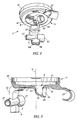
- Figure 1 shows an end-cap assembly 1 mounted at one end of a tubular housing 2 of a filter.
- the end-cap assembly 1 comprises an end-cap 3 having a slightly cambered circular end wall connected to a cylindrical peripheral wall by which the end-cap 3 is secured to the housing 2 of the filter.
- the circular end wall of the end-cap 3 is substantially perpendicular to the longitudinal axis of the housing 2, and the central axis 9 of the end-cap 3 coincides with the longitudinal axis of the housing 2.
- the end-cap assembly 1 further comprises a nozzle 8 made integral with the end-cap 3 so as to form an inlet port that gives access to the interior of the end-cap 3, and a tubular holder 5 for an end of a pump hose 4 of a peristaltic pump.
- the tubular holder 5 is secured to the nozzle 8 by welding or gluing or it can be formed integral with the nozzle 8.
- the tubular holder 5 has a larger section at one end for connection to a pump hose 4 and a smaller section at the other end for connection to a tube 7 forming the downstream part of the arterial blood line of an extracorporeal blood treatment system.
- the tubular holder 5 is so positioned with respect to the nozzle 8 as to be further apart from the end-cap 3 than the nozzle 8. It results from this arrangement that, when a first (or downstream) end 4a of a pump hose 4 is connected to the inlet port 8 and the second (or upstream) end 4b of the pump hose 4 is connected to the tubular holder 5, the first end 4a of the pump hose 4 is offset from the second end 4b along the central axis 9 of the end-cap 3.
- the end-cap assembly 1 is in an operative position, i.e. at a lower point of a filter held vertical, the tubular holder 5 and the upstream end 4b of a pump hose 4 are therefore lower than the nozzle 8 and the downstream end 4a of the pump hose 4.
- the inlet port 8 and the tubular holder 5 are so positioned with respect to each other that when a first end 4a of a pump hose 4 is connected to the inlet port 8 and the second end 4b of the pump hose 4 is connected to the tubular holder 5, the pump hose 4 forms a loop that extends in a plan that is slightly inclined with respect to a plan perpendicular to the central axis 9 of the end-cap assembly 1. Since the tubular holder 5 is lower that the nozzle 8 when the end cap assembly 1 is in an operational position, this arrangement helps gas bubbles move though the hose into the filter and prevents the stagnation of gas bubbles in the pump hose 4.
- a desired angle of inclination of the looped hose 4 with respect to a plane perpendicular to the central axis 9 of the end-cap assembly 1 may be comprised between 3 to 7 degrees, and preferably be about 5 degrees.
- the looped pump hose 4 is adapted to readily cooperate with a peristaltic pump of the rotary type upon connection of the filter to a treatment device (e.g. a dialysis machine).
- a rotary peristaltic pump comprises a rotor generally bearing two rollers at its periphery.
- the rotor is mounted in a support having a semi-circular wall that partially surrounds the rotor and defines a semi-annular gap in which the pump hose 4 can be received.
- the rollers alternately engage the pump hose 4 and squeeze it against the semicircular wall while moving along a circular path, thereby pushing the liquid contained in the pump hose 4 towards the downstream end 4a of the hose.
- the end-cap assembly 1 further comprises two Infusion/injection ports 6a, 6b connected to the tubular holder 5, which can be used for the injection of various substances (e.g. heparin or a substitution solution) to the liquid (e.g. blood) flowing through the filter.
- One of these ports can also be used as a pressure measurement port for connection to a pressure sensor for measuring the pressure of the liquid upstream of the pump hose 4.
- the end-cap assembly 1 also comprises a pressure measurement port 10 connected to the inlet port 8 for connection to a pressure sensor for measuring the pressure of the liquid entering the first compartment of the filter.
- Figures 2 to 4 show a second embodiment of the end-cap assembly 1 of the invention.
- the end-cap assembly 1 is represented without a pump hose connected thereto, whereas in Figures 4 and 5 a pump hose 4 is connected to the inlet port 8 and to the holder 5, 23.
- the end-cap 3 comprises a circular end-wall portion 14 connected to a peripheral wall portion 12 that is designed for securing the end-cap 3 to the housing of a filter.
- the end-cap 3 has a central axis 9 that coincides with the longitudinal axis of the tubular housing of a filter when the end-cap is mounted at one end of such a housing.
- the circular end wall portion 14 and the peripheral wall portion 12 define an interior region 15 of the end-cap 3.
- the interior region 15 forms a header-chamber when the end-cap 3 is mounted at one end of the housing of a filter.
- the end-cap assembly 1 shown on Figures 2 to 5 has an inlet port 8 that is eccentric with respect to the central axis 9 of the end-cap 3 and is formed integral with the end-wall 14 and of the end-cap 3.
- the inlet port 8 comprises a first (upstream) portion 18 furthest to the end wall 14, a second (downstream) portion 19 closest to the end wall 14, and an intermediate portion 20 connecting the first portion 18 to the second portion 19.
- the first (upstream) portion 18 is cylindrical and has a longitudinal axis slightly inclined with respect to a plane perpendicular to the central axis 9 of the end-cap 3.
- the second (downstream) portion 19 flares towards the interior 15 of the end-cap 3 along an axis generally parallel to the central axis 9.
- the intermediate portion 20 has a curvature 16 selected so as to facilitate a smooth an unimpeded flow of a liquid pumped into the end cap 3.
- the downstream flaring portion 19 also has a curvature 17 selected so as to evenly direct a liquid pumped into the end cap 3 towards the apertures of the hollow fibers 25 at the outer surface of a disk 26 of potting material, when the end-cap assembly is mounted at one end of a filter housing 2 ( Figure 5).
- the geometry of the inlet port 8 therefore ensures a smooth passage and distribution of a liquid therethrough and into the interior region 15.
- the radius of the curvature 16 of the intermediate portion 20 and the radius of the curvature 17 of the second portion 19 may be equal.
- a suitable value for both radii lies in the range of about 6 to 12 mm, preferably about 9 mm.
- the end-cap assembly 1 further comprises a first holder for a pump hose 4 having a leg 23 protruding at the periphery of the end-cap 3 and a tubular connector 5 connected to the leg 23 so that the longitudinal axis of the tubular connector 5 is substantially parallel to a line tangential to the circular end wall portion 14 of the end-cap 3. It results from this arrangement that the inlet port 8 and the tubular connector 5 are spaced apart with respect to the central axis 9, both axially and longitudinally, the inlet port 8 being closer to the end-cap 3 than the connector 5.
- a pump hose 4 connected to the tubular connector 5 and the inlet port 8 forms a loop that is therefore slightly inclined with respect to a plan perpendicular to the central axis 9, with the upstream end 4b of the pump hose 4 lower than the downstream end 4a of the pump hose 4 when the end cap assembly 1 is in an operational position as shown in Figure 5.
- a suitable angle of inclination for helping degas the pump hose 4 during the priming of a filter is in the range of 3 to 7 degrees, preferably 5 degrees.
- the first holder 5, 23 may be formed integral with the end-cap 3, or it may be fixed to the end-cap 3 for example by bonding or by welding.
- the tubular connector 5 comprises a first socket 21 of larger section at one end for connection to a pump hose 4 and a second socket 27 of a smaller section at the other end for connection to a tube (e.g. an arterial blood line).
- the socket 27 can comprise a Luer connection element (not shown) for attachment to a tube fitted with a complementary Luer connection element.
- the connector 5 also comprises two ports 6a, 6b that can be used for infusing a liquid into the filter or to measure the pressure in the liquid upstream of a peristaltic pump.
- the end-cap assembly represented in Figures 2 to 5 further comprises a second holder 22 for the pump hose 4 comprising an arm extending outwards, from the periphery of the end-cap 3, substantially opposite the first holder 5, 23 with respect to the inlet port 8.
- the second holder 22 comprises a grip at its outer end for receiving and holding a portion of the pump hose 4.
- the inlet port 8 and the second holder 22 are so arranged with respect to each other that, when the first end 4a of a pump hose 4 is secured to the inlet port 8 and the second end 4b of the pump hose 4 is secured to the first holder 5, 23, the pump hose 4 has a first portion that extends straight from the inlet port 8 to the second holder 22 and a second U-shaped portion that extends from the second holder 22 to the first holder 5, 23.
- the pump hose 4 is bent by the second holder 22, just upstream of the second holder 22 ( Figure 4).
- the second holder 22 gives rigidity to the pump hose 4 and thereby facilitates the positioning of the pump hose 4 around the rotor of a peristaltic pump of a treatment machine.
- the second holder 22 can be formed integral with the end-cap 3, or it can be attached to the end-cap by e.g. bonding or welding.
- Figure 5 shows the end-cap assembly 1 of Figures 2 to 4 connected to the housing 2 of a hollow fiber filter.
- a liquid represented by arrows, flows through the pump hose 4 and enters via the inlet port 8 into the header chamber 15 of the filter, which is delimited by the interior surface of the end-cap 3 and the outer surface of a disk of potting material 26 in which one end of a bundle of hollow fibers 25 is embedded.
- Figure 6 shows a third embodiment of the end-cap assembly according to the invention.
- the first holder 5, 23 of this end-cap assembly is removable.
- the end-cap 3 comprises a fixation element in the form of two parallel grooves 13, and the leg 23 of the holder comprises a complementary fixation element in the form of two parallel tongues 11 designed to snugly fit in the grooves 13 when they are engaged therein.
- the tubular connector 5 comprises three ports 6a, 6b, 6c opening opposite the end-cap 3, which can be used for injecting or infusing various liquids (e.g. heparin and a substitution solution) and for connection to a pressure sensor.
- the second holder 22 is connected to the inlet port 8 and it comprises a curved portion that leads to a tubular clip 24 forming the outer end of the holder.
- the clip 24 is resilient and can be opened so as to receive a portion of a pump hose that it snugly holds when closed.
- the curved portion of the second holder 22 forms a partial cradle for a portion of pump hose when a pump hose is connected to the inlet port 8 ant to the tubular connector 5, while passing through the clip 24.
- the respective dimension and orientation of the inlet port 6 and the connector 5 are such that they are spaced apart axially and longitudinally with respect to the central axis of the end-cap 3, and that a pump hose connected thereto would form a loop slightly inclined with respect to a plane perpendicular to this central axis.
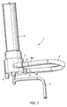
- Figure 7 shows a fourth embodiment of the end-cap assembly according to the invention.
- the end-cap 3 comprises a tubular skirt to which an end portion of the inlet port 8 and of an end portion the holder 5 are connected so as to lie in a plane substantially perpendicular to the longitudinal axis of the filter.
- a pump hose 4 is connected to the inlet port 8 and to the connector 5 and forms a loop that extends in the same plane.
- Figures 8 to 11b show a fifth embodiment of the end-cap assembly 1 according to the invention.
- the holder does not comprise a tubular connector as in the embodiments of Figures 2 to 6, but instead its leg 23 is connected to and made integral with a resilient clip 50 having a C-shaped socket 51.
- the clip 50 has a longitudinal slit-like mouth 52 for allowing the engagement of a tubular connector 53 into the socket 51.
- the connector 53 has an outside diameter corresponding to the diameter of the C-shaped socket 51 and it comprises two circular end flanges 54 for preventing the connector 53 from longitudinally moving within the socket 51 when the connector 53 is engaged in the clip 50.
- the tubular connector 53 is connected to the second end 4b of a pump hose 4, the first end 4a of which is either permanently connected to the inlet port 8 of the end-cap 3 or comprises a connecting element 4c, for example of the Luer type, for connection to a complementary connecting element included in the outlet port 8.
- the tubular connector 53 can also be pre-connected to a tube 7, as shown in Figures 10a and 11a, which represent an arterial blood line in which the tube 7 used for supplying blood from a patient to a hemodialyzer has a smaller diameter than the diameter of the pump hose 4.
- the inner bore of the connector 53 comprises a first end portion with a smaller diameter corresponding to the outer diameter of the tube 7, a second end portion with a larger diameter corresponding to the outer diameter of the pump hose 4 and an intermediary portion flaring from the first end portion to the second end portion.
- the arterial blood line comprises a connecting element at both ends, one of which is the connector element 4c adapted to the inlet port 8, the other connector element being designed for connection to a cannula.
- the internal bore of the connector 53 is cylindrical and corresponds to the outer diameter of the pump hose 4 and the tube 7 that can be made of the same piece of tubing (see Figures 10b and 11b).
- the connector 53 is merely slipped on the piece of tubing before being glued thereto at the appropriate location.
- Figure 12 shows a sixth embodiment of the end-cap assembly 1 according to the invention.
- This end-cap assembly substantially differs from the previously described embodiments in that it is designed to hold a pump hose 4 in a plane containing the central axis b of the end-cap 3.
- Figure 12 represents an end portion of a filter having a tubular housing 2 containing a bundle of hollow fibers 25 secured to the housing 2 at the end thereof by a disk of potting material 26 in which the end of the fibers 25 are embedded.
- the housing 2 is closed by an end-cap 3 having a circular end wall whose central axis 9 coincides with the longitudinal axis 9 of the housing 2.
- a pump hose support 30 in the form of an elongated rectangular parallelepiped is connected to the end-cap 3 so that the longitudinal axis of the support 30 coincides with the central axis 9 of the end-cap 3.
- the pump hose support 30 comprises two separate parts 31 and 32 that can be connected together by a mechanical coupling (not shown).
- the first part 31 of the pump hose support 30, which can be made integral with the end-cap 3, comprises a pressure measurement chamber 33 having a first and a second compartments separated by a flexible membrane 34 that lies in the plane of the figure.
- the first compartment of the pressure chamber 33 communicates with the end-cap 3 through a first portion 8a of an inlet port that extends along the central axis 9 of the end-cap 3.
- the first compartment of the pressure chamber 33 is also connected to the first end 4a of a pump hose 4 through a second portion 8b of the inlet port, whose longitudinal axis is perpendicular to the longitudinal axis 9 of the support 30.
- the first compartment of the pressure measurement chamber 33 can also be connected to a source of liquid (e.g. an infusion liquid) through a port 6 opposite to the second portion 8b of the inlet port.
- the second compartment of the pressure measurement chamber 33 comprises an aperture 10 for the connection to a pressure sensor for the measurement of the pressure of the liquid downstream of the pump hose 4.
- the second part 32 of the pump hose support 30 also comprises a pressure measurement chamber 37 having a first and a second compartments separated by a flexible membrane 38 that lies in the plane of the figure.
- the first compartment of the pressure chamber 37 is connected to a supply tube 7 through a channel 39 that extends along the longitudinal axis of the pump hose support 30.
- the first compartment of the pressure measurement chamber 37 is also connected to the second end 4b of the pump hose 4 through a channel 40, whose longitudinal axis is perpendicular to the longitudinal axis of the support 30.
- the first compartment can be connected to a source of liquid by a port 6 opposite to the channel 39.
- the second compartment of the pressure measurement chamber 37 comprises an aperture 10 for the connection to a pressure sensor for the measurement of the pressure of the liquid upstream of the pump hose 4.
Abstract
Description
- The present invention relates to an end-cap assembly for a filter, in particular, to an end-cap assembly for a hollow fiber filter. The invention also relates to a filter comprising such an end-cap assembly.
- A conventional hollow fiber filter comprises a tubular housing, a semi-permeable membrane in the form a bundle of hollow fibers extending within the housing and secured thereto at both ends, and two end-caps closing the housing at both ends. The ends of the fibers are secured to the housing by a potting material in which they are embedded. The potting material forms a disk that extends perpendicularly to the longitudinal axis of the housing. The ends of the fibers open on an outer surface of the disks of potting material. By construction, such a hollow fiber filter therefore comprises a first and the second compartments isolated from each other: the first compartment includes the interior of the hollow fibers and the space delimited at each end of the filter between the outer surface of the disk of potting material and the inner surface of the end-cap, and the second compartment includes the space outside of the hollow fibers that is delimited by the inner surface of the housing and the inner surface of the disks of potting material. Each end-cap comprises an inlet/outlet nozzle through which a liquid can be flown into and out of the first compartment. The housing is also fitted with one or two nozzle that gives access to the second compartment.
- Hollow fiber filters are used in particular in various extracorporeal treatments of blood, such as hemodialysis, hemofiltration, hemodiafiltration, plasmapheresis. The same type of filter, usually referred to as hemodialyzer or hemofilter, is used for hemodialysis, hemofiltration, hemodiafiltration. The main difference between a hemodialyzer and a plasmafilter (i.e. a filter used in plasmapheresis) is the pore size of their respective membrane, a membrane for plasmapheresis allowing the proteins contained in blood to migrate therethough, whereas a membrane for hemodialysis does not.
- In all these treatments, blood is withdrawn from the patient, flown through the first compartment of a hollow fiber filter, and returned to the patient. In hemodialysis, a dialysis liquid is simultaneously flown though the second compartment of the filter and the metabolic wastes (urea, creatinine) contained in blood migrate by diffusion through the membrane into the second compartment. In hemofiltration, a pressure difference is created across the membrane so that plasma water flows through the membrane into the second compartment of the filter. Here, metabolic wastes migrate by convection into the second compartment. In order to compensate for the loss of bodily fluid, the patient is simultaneously injected a sterile substitution solution. Hemodiafiltration is a combination of hemodialysis and hemofiltration, and, in this treatment, a dialysis liquid is flown through the second compartment and a substitution liquid is injected into the patient. In plasmapheresis, a pressure difference is created across the membrane so that plasma (i.e. plasma water and proteins) flows through the membrane into the second compartment of the filter. Once treated, the plasma is returned to the patient.
- A machine for performing any of the above treatments comprises a peristaltic pump for withdrawing blood from the patient through a so-called "arterial line" connected at one end to the vascular circuit of the patient and at the other end to the inlet nozzle of the first compartment of a filter, for pumping blood into the filter, and for returning blood to the patient through a so-called "venous line" connected at one end to the outlet nozzle of the first compartment of the filter and at the other end to the vascular circuit of the patient. The machine also usually comprises a first blood pressure sensor for measuring the pressure of blood in the arterial line upstream of the pump, a second blood pressure sensor for measuring the pressure of blood in the arterial line downstream of the pump, a third pressure sensor for measuring the pressure of blood in the venous line, a bubble detector for detecting air bubbles in the venous line and a clamp for closing the venous line, for example when air bubbles are detected by the bubble detector.
- An arterial line typically comprises the following components connected together by segments of flexible tubes: a first Luer connector for connection to an arterial cannula, an arterial bubble trap, a pump hose for cooperating with the rotor of the peristaltic pump of the machine, and a second Luer connector for connection to the inlet nozzle of the first compartment of a filter. A venous line typically comprises the following components connected together by segments of flexible tubes: a first Luer connector for connection to the outlet nozzle of the first compartment of a filter, a venous bubble trap, and a second Luer connector for connection to a venous cannula. Usually, the first and third pressure sensors of the machine are connected to the arterial and venous bubble trap respectively, when the machine, the arterial line the venous line and the filter are assembled in view of a treatment.
- A dialysis machine further comprises a dialysis liquid generator that can be connected through a supply line to the inlet nozzle of the second compartment of a hemodialyzer. The dialysis machine also comprises a waste line by which the outlet nozzle of the hemodialyzer can be connected to the drain. A hollow fiber ultrafilter of similar construction as described above can be connected to the supply line so that an extra pure dialysis liquid is supplied to the hemodialyzer. The invention also applies to such an ultrafilter.
- The assemblage of the arterial and venous line to the filter and to the machine in preparation for a treatment is time consuming, and an object of the invention is to design and end-cap assembly that facilitates such an assemblage.
- According to the invention, an end-cap assembly for closing one end of a housing of a filter, comprises:
- an end-cap having an end wall;
- an inlet port extending through the end wall for connection to a first end of a pump hose of a peristaltic pump; and
- a first holder for securing a second end of the pump hose,
- Within the frame of the invention, "inlet port" means the passage through the end wall of the end-cap as well as any straight or bent nozzle or channel that may extend this passage on the outer side of the end cap.
- This arrangement facilitates the loading of a filter in a machine having a peristaltic pump for circulating a liquid in the filter.
- According to one variant of the invention, the inlet port and the first holder are arranged relative to each other so that the loop formed by the pump hose substantially extends in a plane that is inclined with respect to a plane perpendicular to a central axis of the end-cap. In particular, the inlet port and the first holder are arranged relative to each other so that the first end and second end of the pump hose are longitudinally spaced apart from each other with respect to the central axis of the end-cap and the second end of the pump hose is further apart from the end-cap than the first end of the pump hose.
- When a hemodialyzer or a hemofilter comprising this end-cap assembly is hold in the usual operative position, i.e. substantially vertical, with the end-cap assembly being at the lowest point, this arrangement helps degas the pump hose, in particular when a circuit including the filter is primed with a liquid (e.g. a sterile saline liquid) before the filter is used for treating blood.
- According to another variant of the invention, the inlet port and the first holder are arranged relative to each other so that the loop formed by the pump hose substantially extends in a plane parallel to a central axis of the end-cap when the first end of the pump hose is connected to the inlet port and the second end of the pump hose is secured by the first holder.
- According to one feature of the invention, in order to facilitate the packaging of a filter comprising the end-cap assembly, the first holder is removably mounted on the end-cap.
- According to another feature of the invention, the end-cap assembly comprises a second holder for holding the pump hose between the inlet port and the first holder.
- According to yet another feature of the invention, the end-cap assembly comprises a pump hose connected to the inlet port and the holder, e.g. by gluing or welding.
- Other additional or alternative features of the invention are as follows:
- The inlet port is offset with respect to a central axis of the end-cap.
- The inlet port comprises a first portion furthest to the end wall, a second portion closest to the end wall, and an intermediate portion connecting the first portion to the second portion, wherein the first portion has an axis slightly inclined with respect to a plane perpendicular to a central axis of the end-cap, the second portion flares towards an interior of the end-cap along an axis generally parallel to the central axis of the end-cap and the intermediate portion has a curvature adapted to facilitate a smooth an unimpeded flow of a liquid pumped into the end cap.
- The first holder comprises a tubular connector for connecting the pump hose to a tube.
- The first holder comprises a clip for snugly engaging a tubular connector for connecting the pump hose to a tube. The tubular connector is removable and the clip is designed to resiliently engage and lock the tubular connector.
- The end-cap assembly comprises at least one infusion port connected to the inlet port and a pressure measurement port connected to the inlet port for measuring a pressure of liquid downstream of the pump hose.
- The end-cap assembly comprises at least one infusion port connected to the first holder and a pressure measurement port connected to the first holder for measuring a pressure of liquid upstream of the pump hose.
- Another object of the invention is pump hose for a peristaltic pump adapted to the end cap assembly of the invention. Such a pump hose has a first end fitted with a connecting element for connection to the inlet port and a second end fitted with a connecting element for connection to the first holder
- Still another object of the invention is a filter comprising such an end-cap assembly.
- Other features and advantages of the invention will appear on reading the detailed description that follows. Reference will be made to the appended drawings in which:
- Figure 1 is a perspective view of a portion of a hollow fiber filter comprising an end-cap assembly according to the invention;
- Figure 2 is a perspective view of a second embodiment of an end-cap assembly according to the invention;
- Figure 3 is a cross-section view of the end-cap assembly of Figure 2;
- Figure 4 is a perspective view of the end-cap assembly shown in Figures 2 and 3 fitted with a pump hose;
- Figure 5 is cross-section view of the end-cap assembly of Figures 2 to 4 mounted on an end of a hollow fiber filter;
- Figure 6 is a perspective view of a third embodiment of an end-cap assembly according to the invention;
- Figure 7 is a perspective view of a fourth embodiment of an end-cap assembly according to the invention;
- Figure 8 is a perspective view of a fifth embodiment of an end-cap assembly according to the invention;
- Figures 9a and 9b are perspective views of the two parts of the holder of the end-cap assembly of Figure 8;
- Figures 10a and 10b are longitudinal cross section views of two embodiments of the tubular connector of the holder of the end-cap assembly of Figure 8;
- Figures 11a and 11b are plan views of two arterial blood lines designed to equip the end-cap assembly of Figure 8;
- Figure 12 is a longitudinal cross section view of a sixth embodiment of an end-cap assembly according to the invention.
-
- Figure 1 shows an end-
cap assembly 1 mounted at one end of atubular housing 2 of a filter. The end-cap assembly 1 comprises an end-cap 3 having a slightly cambered circular end wall connected to a cylindrical peripheral wall by which the end-cap 3 is secured to thehousing 2 of the filter. When the end-cap 3 is mounted on thehousing 2 of a filter, as shown, the circular end wall of the end-cap 3 is substantially perpendicular to the longitudinal axis of thehousing 2, and thecentral axis 9 of the end-cap 3 coincides with the longitudinal axis of thehousing 2. The end-cap assembly 1 further comprises anozzle 8 made integral with the end-cap 3 so as to form an inlet port that gives access to the interior of the end-cap 3, and atubular holder 5 for an end of apump hose 4 of a peristaltic pump. Thetubular holder 5 is secured to thenozzle 8 by welding or gluing or it can be formed integral with thenozzle 8. Thetubular holder 5 has a larger section at one end for connection to apump hose 4 and a smaller section at the other end for connection to atube 7 forming the downstream part of the arterial blood line of an extracorporeal blood treatment system. - The
tubular holder 5 is so positioned with respect to thenozzle 8 as to be further apart from the end-cap 3 than thenozzle 8. It results from this arrangement that, when a first (or downstream)end 4a of apump hose 4 is connected to theinlet port 8 and the second (or upstream)end 4b of thepump hose 4 is connected to thetubular holder 5, thefirst end 4a of thepump hose 4 is offset from thesecond end 4b along thecentral axis 9 of the end-cap 3. When the end-cap assembly 1 is in an operative position, i.e. at a lower point of a filter held vertical, thetubular holder 5 and theupstream end 4b of apump hose 4 are therefore lower than thenozzle 8 and thedownstream end 4a of thepump hose 4. - Also, the
inlet port 8 and thetubular holder 5 are so positioned with respect to each other that when afirst end 4a of apump hose 4 is connected to theinlet port 8 and thesecond end 4b of thepump hose 4 is connected to thetubular holder 5, thepump hose 4 forms a loop that extends in a plan that is slightly inclined with respect to a plan perpendicular to thecentral axis 9 of the end-cap assembly 1. Since thetubular holder 5 is lower that thenozzle 8 when theend cap assembly 1 is in an operational position, this arrangement helps gas bubbles move though the hose into the filter and prevents the stagnation of gas bubbles in thepump hose 4. A desired angle of inclination of the loopedhose 4 with respect to a plane perpendicular to thecentral axis 9 of the end-cap assembly 1 may be comprised between 3 to 7 degrees, and preferably be about 5 degrees. - The looped
pump hose 4 is adapted to readily cooperate with a peristaltic pump of the rotary type upon connection of the filter to a treatment device (e.g. a dialysis machine). A rotary peristaltic pump comprises a rotor generally bearing two rollers at its periphery. The rotor is mounted in a support having a semi-circular wall that partially surrounds the rotor and defines a semi-annular gap in which thepump hose 4 can be received. When the rotor rotates, the rollers alternately engage thepump hose 4 and squeeze it against the semicircular wall while moving along a circular path, thereby pushing the liquid contained in thepump hose 4 towards thedownstream end 4a of the hose. - The end-
cap assembly 1 further comprises two Infusion/injection ports tubular holder 5, which can be used for the injection of various substances (e.g. heparin or a substitution solution) to the liquid (e.g. blood) flowing through the filter. One of these ports can also be used as a pressure measurement port for connection to a pressure sensor for measuring the pressure of the liquid upstream of thepump hose 4. The end-cap assembly 1 also comprises apressure measurement port 10 connected to theinlet port 8 for connection to a pressure sensor for measuring the pressure of the liquid entering the first compartment of the filter. - Figures 2 to 4 show a second embodiment of the end-
cap assembly 1 of the invention. In Figures 2 and 3, the end-cap assembly 1 is represented without a pump hose connected thereto, whereas in Figures 4 and 5 apump hose 4 is connected to theinlet port 8 and to theholder cap 3 comprises a circular end-wall portion 14 connected to aperipheral wall portion 12 that is designed for securing the end-cap 3 to the housing of a filter. The end-cap 3 has acentral axis 9 that coincides with the longitudinal axis of the tubular housing of a filter when the end-cap is mounted at one end of such a housing. The circularend wall portion 14 and theperipheral wall portion 12 define aninterior region 15 of the end-cap 3. Theinterior region 15 forms a header-chamber when the end-cap 3 is mounted at one end of the housing of a filter. - The end-
cap assembly 1 shown on Figures 2 to 5 has aninlet port 8 that is eccentric with respect to thecentral axis 9 of the end-cap 3 and is formed integral with the end-wall 14 and of the end-cap 3. Theinlet port 8 comprises a first (upstream)portion 18 furthest to theend wall 14, a second (downstream)portion 19 closest to theend wall 14, and anintermediate portion 20 connecting thefirst portion 18 to thesecond portion 19. The first (upstream)portion 18 is cylindrical and has a longitudinal axis slightly inclined with respect to a plane perpendicular to thecentral axis 9 of the end-cap 3. The second (downstream)portion 19 flares towards the interior 15 of the end-cap 3 along an axis generally parallel to thecentral axis 9. Theintermediate portion 20 has acurvature 16 selected so as to facilitate a smooth an unimpeded flow of a liquid pumped into theend cap 3. At its connection to theend wall 14, thedownstream flaring portion 19 also has acurvature 17 selected so as to evenly direct a liquid pumped into theend cap 3 towards the apertures of thehollow fibers 25 at the outer surface of adisk 26 of potting material, when the end-cap assembly is mounted at one end of a filter housing 2 (Figure 5). The geometry of theinlet port 8 therefore ensures a smooth passage and distribution of a liquid therethrough and into theinterior region 15. - The radius of the
curvature 16 of theintermediate portion 20 and the radius of thecurvature 17 of thesecond portion 19 may be equal. A suitable value for both radii lies in the range of about 6 to 12 mm, preferably about 9 mm. - The end-
cap assembly 1 further comprises a first holder for apump hose 4 having aleg 23 protruding at the periphery of the end-cap 3 and atubular connector 5 connected to theleg 23 so that the longitudinal axis of thetubular connector 5 is substantially parallel to a line tangential to the circularend wall portion 14 of the end-cap 3. It results from this arrangement that theinlet port 8 and thetubular connector 5 are spaced apart with respect to thecentral axis 9, both axially and longitudinally, theinlet port 8 being closer to the end-cap 3 than theconnector 5. Apump hose 4 connected to thetubular connector 5 and theinlet port 8 forms a loop that is therefore slightly inclined with respect to a plan perpendicular to thecentral axis 9, with theupstream end 4b of thepump hose 4 lower than thedownstream end 4a of thepump hose 4 when theend cap assembly 1 is in an operational position as shown in Figure 5. A suitable angle of inclination for helping degas thepump hose 4 during the priming of a filter is in the range of 3 to 7 degrees, preferably 5 degrees. - The
first holder cap 3, or it may be fixed to the end-cap 3 for example by bonding or by welding. Thetubular connector 5 comprises afirst socket 21 of larger section at one end for connection to apump hose 4 and asecond socket 27 of a smaller section at the other end for connection to a tube (e.g. an arterial blood line). Thesocket 27 can comprise a Luer connection element (not shown) for attachment to a tube fitted with a complementary Luer connection element. Theconnector 5 also comprises twoports - The end-cap assembly represented in Figures 2 to 5 further comprises a
second holder 22 for thepump hose 4 comprising an arm extending outwards, from the periphery of the end-cap 3, substantially opposite thefirst holder inlet port 8. Thesecond holder 22 comprises a grip at its outer end for receiving and holding a portion of thepump hose 4. Theinlet port 8 and thesecond holder 22 are so arranged with respect to each other that, when thefirst end 4a of apump hose 4 is secured to theinlet port 8 and thesecond end 4b of thepump hose 4 is secured to thefirst holder pump hose 4 has a first portion that extends straight from theinlet port 8 to thesecond holder 22 and a second U-shaped portion that extends from thesecond holder 22 to thefirst holder pump hose 4 is bent by thesecond holder 22, just upstream of the second holder 22 (Figure 4). Thesecond holder 22 gives rigidity to thepump hose 4 and thereby facilitates the positioning of thepump hose 4 around the rotor of a peristaltic pump of a treatment machine. Thesecond holder 22 can be formed integral with the end-cap 3, or it can be attached to the end-cap by e.g. bonding or welding. - Figure 5 shows the end-
cap assembly 1 of Figures 2 to 4 connected to thehousing 2 of a hollow fiber filter. A liquid, represented by arrows, flows through thepump hose 4 and enters via theinlet port 8 into theheader chamber 15 of the filter, which is delimited by the interior surface of the end-cap 3 and the outer surface of a disk ofpotting material 26 in which one end of a bundle ofhollow fibers 25 is embedded. - Figure 6 shows a third embodiment of the end-cap assembly according to the invention. The
first holder cap 3 comprises a fixation element in the form of twoparallel grooves 13, and theleg 23 of the holder comprises a complementary fixation element in the form of twoparallel tongues 11 designed to snugly fit in thegrooves 13 when they are engaged therein. Thetubular connector 5 comprises threeports cap 3, which can be used for injecting or infusing various liquids (e.g. heparin and a substitution solution) and for connection to a pressure sensor. In this embodiment, thesecond holder 22 is connected to theinlet port 8 and it comprises a curved portion that leads to atubular clip 24 forming the outer end of the holder. Theclip 24 is resilient and can be opened so as to receive a portion of a pump hose that it snugly holds when closed. The curved portion of thesecond holder 22 forms a partial cradle for a portion of pump hose when a pump hose is connected to theinlet port 8 ant to thetubular connector 5, while passing through theclip 24. Here also it can be noted that the respective dimension and orientation of theinlet port 6 and theconnector 5 are such that they are spaced apart axially and longitudinally with respect to the central axis of the end-cap 3, and that a pump hose connected thereto would form a loop slightly inclined with respect to a plane perpendicular to this central axis. - Figure 7 shows a fourth embodiment of the end-cap assembly according to the invention. In this embodiment, the end-
cap 3 comprises a tubular skirt to which an end portion of theinlet port 8 and of an end portion theholder 5 are connected so as to lie in a plane substantially perpendicular to the longitudinal axis of the filter. Apump hose 4 is connected to theinlet port 8 and to theconnector 5 and forms a loop that extends in the same plane. - Figures 8 to 11b show a fifth embodiment of the end-
cap assembly 1 according to the invention. In this embodiment, the holder does not comprise a tubular connector as in the embodiments of Figures 2 to 6, but instead itsleg 23 is connected to and made integral with aresilient clip 50 having a C-shapedsocket 51. Theclip 50 has a longitudinal slit-like mouth 52 for allowing the engagement of atubular connector 53 into thesocket 51. Theconnector 53 has an outside diameter corresponding to the diameter of the C-shapedsocket 51 and it comprises twocircular end flanges 54 for preventing theconnector 53 from longitudinally moving within thesocket 51 when theconnector 53 is engaged in theclip 50. - The
tubular connector 53 is connected to thesecond end 4b of apump hose 4, thefirst end 4a of which is either permanently connected to theinlet port 8 of the end-cap 3 or comprises a connecting element 4c, for example of the Luer type, for connection to a complementary connecting element included in theoutlet port 8. - The
tubular connector 53 can also be pre-connected to atube 7, as shown in Figures 10a and 11a, which represent an arterial blood line in which thetube 7 used for supplying blood from a patient to a hemodialyzer has a smaller diameter than the diameter of thepump hose 4. In such a case, the inner bore of theconnector 53 comprises a first end portion with a smaller diameter corresponding to the outer diameter of thetube 7, a second end portion with a larger diameter corresponding to the outer diameter of thepump hose 4 and an intermediary portion flaring from the first end portion to the second end portion. The arterial blood line comprises a connecting element at both ends, one of which is the connector element 4c adapted to theinlet port 8, the other connector element being designed for connection to a cannula. - When an arterial blood line comprises a
pump hose 4 and asupply tube 7 having the same diameter, the internal bore of theconnector 53 is cylindrical and corresponds to the outer diameter of thepump hose 4 and thetube 7 that can be made of the same piece of tubing (see Figures 10b and 11b). In this case, theconnector 53 is merely slipped on the piece of tubing before being glued thereto at the appropriate location. - Figure 12 shows a sixth embodiment of the end-
cap assembly 1 according to the invention. This end-cap assembly substantially differs from the previously described embodiments in that it is designed to hold apump hose 4 in a plane containing the central axis b of the end-cap 3. - In more details, Figure 12 represents an end portion of a filter having a
tubular housing 2 containing a bundle ofhollow fibers 25 secured to thehousing 2 at the end thereof by a disk ofpotting material 26 in which the end of thefibers 25 are embedded. Thehousing 2 is closed by an end-cap 3 having a circular end wall whosecentral axis 9 coincides with thelongitudinal axis 9 of thehousing 2. Apump hose support 30 in the form of an elongated rectangular parallelepiped is connected to the end-cap 3 so that the longitudinal axis of thesupport 30 coincides with thecentral axis 9 of the end-cap 3. Thepump hose support 30 comprises twoseparate parts - The
first part 31 of thepump hose support 30, which can be made integral with the end-cap 3, comprises apressure measurement chamber 33 having a first and a second compartments separated by aflexible membrane 34 that lies in the plane of the figure. The first compartment of thepressure chamber 33 communicates with the end-cap 3 through afirst portion 8a of an inlet port that extends along thecentral axis 9 of the end-cap 3. The first compartment of thepressure chamber 33 is also connected to thefirst end 4a of apump hose 4 through a second portion 8b of the inlet port, whose longitudinal axis is perpendicular to thelongitudinal axis 9 of thesupport 30. The first compartment of thepressure measurement chamber 33 can also be connected to a source of liquid (e.g. an infusion liquid) through aport 6 opposite to the second portion 8b of the inlet port. The second compartment of thepressure measurement chamber 33 comprises anaperture 10 for the connection to a pressure sensor for the measurement of the pressure of the liquid downstream of thepump hose 4. - The
second part 32 of thepump hose support 30 also comprises apressure measurement chamber 37 having a first and a second compartments separated by aflexible membrane 38 that lies in the plane of the figure. The first compartment of thepressure chamber 37 is connected to asupply tube 7 through achannel 39 that extends along the longitudinal axis of thepump hose support 30. The first compartment of thepressure measurement chamber 37 is also connected to thesecond end 4b of thepump hose 4 through achannel 40, whose longitudinal axis is perpendicular to the longitudinal axis of thesupport 30. The first compartment can be connected to a source of liquid by aport 6 opposite to thechannel 39. The second compartment of thepressure measurement chamber 37 comprises anaperture 10 for the connection to a pressure sensor for the measurement of the pressure of the liquid upstream of thepump hose 4. - The various embodiments of the invention described above are only to exemplify the invention. The scope of the invention is therefore not limited to any of them.
Claims (24)
- End-cap assembly (1) for closing one end of a housing (2) of a filter, comprising an end-cap (3) having an end wall (14), characterized in that it comprises:wherein the inlet port (8; 8a,8b) and the first holder (5; 5,23; 50,23; 32) are arranged relative to each other so that the pump hose (4) forms a loop when the first end (4a) the pump hose (4) is connected to the inlet port (8) and the second end (4b) of the pump hose (4) is secured by the holder (5; 5,23; 50,23; 32).an inlet port (8; 8a,8b) extending through the end wall (14) for connection to a first end (4a) of a pump hose (4) of a peristaltic pump; anda first holder (5; 5,23; 50,23; 32) for securing a second end (4b) of the pump hose (4),
- End-cap assembly (1) according to claim 1, characterized in that the inlet port (8) and the first holder (5; 5,23; 50,23) are arranged relative to each other so that the loop formed by the pump hose (4) substantially extends in a plane that is inclined with respect to a plane perpendicular to a central axis (9) of the end-cap (3).
- End-cap assembly (1) according to one of the claims 1 and 2, characterized in that the inlet port (8; 8a,8b) and the first holder (5; 5,23; 50,23; 32) are arranged relative to each other so that the first end (4a) and second end (4b) of the pump hose (4) are longitudinally spaced apart from each other with respect to a central axis (9) of the end-cap (3) when the first end (4a) of the pump hose (4) is connected to the inlet port (8; 8a,8b) and the second end (4b) of the pump hose (4) is secured by the first holder (5; 5,23; 50,23; 32).
- End-cap assembly (1) according to claim 3, characterized in that the inlet port (8; 8a,8b) and the holder (5; 5,23; 50,23; 32) are arranged relative to each other so that the second end (4b) of the pump hose (4) is further apart from the end-cap (3) than the first end (4a) of the pump hose (4) when the first end (4a) of the pump hose (4) is connected to the inlet port (8; 8a,8b) and the second end (4b) of the pump hose (4) is secured by the first holder (5; 5,23; 50,23; 32).
- End-cap assembly (1) according to one of the claims 1 to 5, characterized in that the inlet port (8; 8a,8b) and the holder (5; 32) are arranged relative to each other so that the first end (4a) and second end (4b) of the pump hose (4) are adjacent to a central axis (9) of the end-cap (3) when the first end (4a) of the pump hose (4) is connected to the inlet port (8; 8a,8b) and the second end (4b) of the pump hose (4) is secured by the first holder (5; 32).
- End-cap assembly (1) according to one of the claims 1 to 5, characterized in that the inlet port (8) and the holder (5; 5,23; 50,23) are arranged relative to each other so that the first end (4a) and second end (4b) of the pump hose (4) are radially spaced apart from each other with respect to a central axis (9) of the end-cap (3) when the first end (4a) of the pump hose (4) is connected to the inlet port (8) and the second end (4b) of the pump hose (4) is secured by the first holder (5; 5,23; 50,23).
- End-cap assembly (1) according to one of the claims 1 to 6, characterized in that the inlet port (8) is offset with respect to a central axis (9) of the end-cap (3).
- End-cap assembly (1) according to one of the claims 1 to 7, characterized in that the inlet port (8) comprises a first portion (18) furthest to the end wall (14), a second portion (19) closest to the end wall (14), and an intermediate portion (20) connecting the first portion (18) to the second portion (19), wherein the first portion (18) has an axis slightly inclined with respect to a plane perpendicular to a central axis (9) of the end-cap (3), the second portion (19) flares towards an interior (15) of the end-cap (3) along an axis generally parallel to the central axis (9) of the end-cap (3) and the intermediate portion (20) has a curvature adapted to facilitate a smooth an unimpeded flow of a liquid pumped into the end cap (3).
- End-cap assembly (1) according to one of the claims 1 to 8, characterized in that the first holder (5; 5,23) comprises a tubular connector (5) for connecting a pump hose (4) to a tube (7).
- End-cap assembly (1) according to one of the claims 1 to 8, characterized in that the first holder (50, 23) comprises a clip (50) for snugly engaging a tubular connector (53) for connecting a pump hose (4) to a tube (7).
- End-cap assembly (1) according to claim 10, characterized in that the tubular connector (53) is removable and the clip (50) is designed to resiliently engage and lock the tubular connector (53).
- End-cap assembly (1) according to one of the claims 1 to 11, characterized in that the first holder (5,23; 50,23) comprises a leg (23) protruding at a periphery of the end wall (14) of the end-cap (3) for holding the second end (4b) of a pump hose (4) longitudinally and radially spaced apart from the central axis (9) of the end-cap (3).
- End-cap assembly (1) according to one of the claims 1 to 12, characterized in that it further comprises a second holder (22) for holding a pump hose (4) between the inlet port (8) and the first holder (5).
- End-cap assembly (1) according to claim 13, characterized in that the second holder (22) comprises an arm protruding at a periphery of the end wall (14) of the end-cap (3) for holding the pump hose (4) radially spaced apart from the central axis (9) of the end-cap (3).
- End-cap assembly (1) according to claim 1, characterized in that the inlet port (8a,8b) and the first holder (32) are arranged relative to each other so that the loop formed by a pump hose (4) substantially extends in a plane parallel to a central axis (9) of the end-cap (3) when the first end (4a) of the pump hose (4) is connected to the inlet port (8a,8b) and the second end (4b) of the pump hose (4) is secured by the first holder (32).
- End-cap assembly (1) according to one of the claims 1 to 15, characterized in that the first holder (5,23; 32) is removably mounted on the end-cap (3).
- End-cap assembly (1) according to one of the claims 1 to 16, characterized in that it further comprises at least one infusion port (6) connected to the inlet port (8a,8b).
- End-cap assembly (1) according to one of the claims 1 to 17, characterized in that it further comprises a pressure measurement port (10) connected to the inlet port (8; 8a,8b) for measuring a pressure of liquid in the first end (4a) of a pump hose (4).
- End-cap assembly (1) according to one of the claims 1 to 18, characterized in that it further comprises at least one infusion port (6a, 6b, 6c) connected to the first holder (5; 5,23; 32).
- End-cap assembly (1) according one of the claims 1 to 19, characterized in that it further comprises a pressure measurement port (10) connected to the first holder (5, 32) for measuring a pressure of liquid in the second end (4b) of a pump hose (4).
- End-cap assembly (1) according to one of the claims 1 to 20, characterized in that it further comprises a pump hose (4) connected to the inlet port (8; 8a,8b) and the holder (5; 5,23; 50,23; 32).
- Pump hose (4) for a peristaltic pump adapted to the end-cap assembly (1) of one of the claims 1 to 18, the pump hose (4) having a first end (4a) fitted with a connecting element for connection to the inlet port (8; 8a,8b) and a second end (4b) fitted with a connecting element for connection to the first holder (5; 5,23; 50,23; 32).
- Filter comprising an end-cap assembly according to one of the claims 1 to 21.
- Filter according to claim 23, comprising a semi-permeable membrane adapted to hemodialysis or hemofiltration.
Priority Applications (1)
| Application Number | Priority Date | Filing Date | Title |
|---|---|---|---|
| EP04024751A EP1530995B1 (en) | 2003-11-07 | 2004-10-18 | End-cap assembly with pump hose for a filter and filter comprising such an end-cap assembly |
Applications Claiming Priority (3)
| Application Number | Priority Date | Filing Date | Title |
|---|---|---|---|
| EP03025640 | 2003-11-07 | ||
| EP03025640 | 2003-11-07 | ||
| EP04024751A EP1530995B1 (en) | 2003-11-07 | 2004-10-18 | End-cap assembly with pump hose for a filter and filter comprising such an end-cap assembly |
Publications (2)
| Publication Number | Publication Date |
|---|---|
| EP1530995A1 true EP1530995A1 (en) | 2005-05-18 |
| EP1530995B1 EP1530995B1 (en) | 2007-02-21 |
Family
ID=34560156
Family Applications (1)
| Application Number | Title | Priority Date | Filing Date |
|---|---|---|---|
| EP04024751A Not-in-force EP1530995B1 (en) | 2003-11-07 | 2004-10-18 | End-cap assembly with pump hose for a filter and filter comprising such an end-cap assembly |
Country Status (11)
| Country | Link |
|---|---|
| US (1) | US8403150B2 (en) |
| EP (1) | EP1530995B1 (en) |
| KR (1) | KR101188573B1 (en) |
| CN (3) | CN100406108C (en) |
| AT (1) | ATE354429T1 (en) |
| AU (1) | AU2004286774B2 (en) |
| CA (1) | CA2543519C (en) |
| DE (1) | DE602004004857T2 (en) |
| ES (1) | ES2282775T3 (en) |
| HK (1) | HK1097792A1 (en) |
| WO (1) | WO2005044428A1 (en) |
Families Citing this family (28)
| Publication number | Priority date | Publication date | Assignee | Title |
|---|---|---|---|---|
| AU2008251056B2 (en) * | 2007-05-15 | 2013-01-10 | Gambro Lundia Ab | Pressure sensing device and use of the same in a connecting structure |
| EP2113266A1 (en) * | 2008-04-30 | 2009-11-04 | Gambro Lundia AB | Degassing device |
| GB0812457D0 (en) * | 2008-07-08 | 2008-08-13 | Parker Hannifin U K Ltd | A Filter |
| DE102009038571B4 (en) * | 2009-08-22 | 2011-07-14 | Völker, Manfred, 63825 | Supply device for dialysis machines |
| US9228575B2 (en) * | 2010-11-16 | 2016-01-05 | Zoeller Pump Company, Llc | Sealed and self-contained tankless water heater flushing system |
| US9173987B2 (en) * | 2013-02-01 | 2015-11-03 | Medtronic, Inc. | Degassing module for a controlled compliant flow path |
| US9404488B2 (en) * | 2013-02-19 | 2016-08-02 | Wabtec Holding Corp. | Pressurized oil delivery system for a reciprocating air compressor |
| DK3335751T3 (en) | 2013-08-29 | 2021-03-22 | Sanofi Sa | SAFETY DEVICE FOR A MEDICINE CONTAINER |
| KR102121918B1 (en) * | 2013-12-20 | 2020-06-11 | 삼성전자주식회사 | Method and apparatus for event notification in home network system |
| WO2017092795A1 (en) * | 2015-12-01 | 2017-06-08 | Ateliers Busch S.A. | Vacuum pump with filtering element |
| SG11201901156PA (en) * | 2016-10-20 | 2019-03-28 | Emd Millipore Corp | Valve protection and tube management device |
| WO2018226991A1 (en) | 2017-06-07 | 2018-12-13 | Shifamed Holdings, Llc | Intravascular fluid movement devices, systems, and methods of use |
| WO2019094963A1 (en) | 2017-11-13 | 2019-05-16 | Shifamed Holdings, Llc | Intravascular fluid movement devices, systems, and methods of use |
| EP3746149A4 (en) | 2018-02-01 | 2021-10-27 | Shifamed Holdings, LLC | Intravascular blood pumps and methods of use and manufacture |
| CN108295326B (en) * | 2018-02-09 | 2021-03-26 | 苏州卓壹医疗器械有限公司 | Double-cavity ultrapure hemodialyzer |
| JP6577626B1 (en) * | 2018-05-02 | 2019-09-18 | 日機装株式会社 | Air trap chamber and extracorporeal circuit |
| USD910081S1 (en) * | 2019-02-14 | 2021-02-09 | Fleece Performance Engineering, Inc. | Pump cap |
| USD910082S1 (en) * | 2019-04-17 | 2021-02-09 | Fleece Performance Engineering, Inc. | Pump cap |
| USD910083S1 (en) * | 2019-05-08 | 2021-02-09 | Fleece Performance Engineering, Inc. | Pump cap |
| WO2021016372A1 (en) | 2019-07-22 | 2021-01-28 | Shifamed Holdings, Llc | Intravascular blood pumps with struts and methods of use and manufacture |
| WO2021062265A1 (en) | 2019-09-25 | 2021-04-01 | Shifamed Holdings, Llc | Intravascular blood pump systems and methods of use and control thereof |
| CA3160967A1 (en) | 2019-11-12 | 2021-05-20 | Fresenius Medical Care Deutschland Gmbh | Blood treatment systems |
| WO2021094140A1 (en) | 2019-11-12 | 2021-05-20 | Fresenius Medical Care Deutschland Gmbh | Blood treatment systems |
| WO2021094139A1 (en) | 2019-11-12 | 2021-05-20 | Fresenius Medical Care Deutschland Gmbh | Blood treatment systems |
| CA3160952A1 (en) * | 2019-11-12 | 2021-05-20 | Fresenius Medical Care Deutschland Gmbh | Blood treatment systems |
| EP3900814A1 (en) * | 2020-04-23 | 2021-10-27 | Bellco S.r.l. | Dialyzer header cap |
| USD996211S1 (en) * | 2020-05-18 | 2023-08-22 | Illinois Tool Works Inc. | Sealant bottle cap |
| USD985632S1 (en) * | 2021-06-30 | 2023-05-09 | Fleece Performance Engineering, Inc. | Pump cap |
Citations (2)
| Publication number | Priority date | Publication date | Assignee | Title |
|---|---|---|---|---|
| US4493693A (en) * | 1982-07-30 | 1985-01-15 | Baxter Travenol Laboratories, Inc. | Trans-membrane pressure monitoring system |
| US4605503A (en) * | 1983-05-26 | 1986-08-12 | Baxter Travenol Laboratories, Inc. | Single needle blood fractionation system having adjustable recirculation through filter |
Family Cites Families (49)
| Publication number | Priority date | Publication date | Assignee | Title |
|---|---|---|---|---|
| US4436620A (en) | 1977-05-09 | 1984-03-13 | Baxter Travenol Laboratories, Inc. | Integral hydraulic circuit for hemodialysis apparatus |
| US4231871A (en) | 1977-06-10 | 1980-11-04 | Cordis Dow Corp. | Artificial kidney and method for making same |
| US4379452A (en) | 1977-10-18 | 1983-04-12 | Baxter Travenol Laboratories, Inc. | Prepackaged, self-contained fluid circuit module |
| DE2818390C2 (en) | 1978-04-27 | 1986-10-30 | Fresenius AG, 6380 Bad Homburg | Artificial organ |
| JPS55114A (en) | 1978-06-15 | 1980-01-05 | Honda Motor Co Ltd | Dialyzer device in artificial kidney device |
| US4263808A (en) * | 1979-03-26 | 1981-04-28 | Baxter Travenol Laboratories, Inc. | Noninvasive pressure monitor |
| US4227420A (en) | 1979-06-11 | 1980-10-14 | Baxter Travenol Laboratories, Inc. | Pressure coupling mechanism in a pressure monitoring assembly |
| US4293413A (en) | 1979-12-28 | 1981-10-06 | Baxter Travenol Laboratories, Inc. | Dialyzer blood circuit and bubble traps |
| US4344777A (en) | 1980-01-07 | 1982-08-17 | Siposs George G | Directed flow bubble trap for arterial blood |
| US4368118A (en) | 1980-01-07 | 1983-01-11 | Siposs George G | Blood-air separator and filter |
| FR2491336A1 (en) | 1980-10-06 | 1982-04-09 | Hospal Sodip | ARTIFICIAL RESIN WITH DIALYSIS LIQUID CIRCUIT FOR SINGLE USE |
| FR2493706A1 (en) | 1980-11-13 | 1982-05-14 | Hospal Sodip | ARTIFICIAL KIDNEY WITH INTEGRATED DIALYSIS LIQUID CIRCUIT |
| FR2507481B1 (en) | 1981-06-16 | 1985-06-14 | Hospal Sodip | ARTIFICIAL KIDNEY WITH INTEGRATED CIRCUITS |
| US4412916A (en) | 1981-06-24 | 1983-11-01 | Cordis Dow Corp. | Airless artificial kidney assembly |
| US4433971A (en) * | 1981-06-30 | 1984-02-28 | Minnesota Mining And Manufacturing Company | Integrated cardioplegia delivery system |
| IL64001A0 (en) | 1981-10-06 | 1982-01-31 | Elmar Medical Systems Ltd | Blood treatment system |
| US4582598A (en) | 1981-12-15 | 1986-04-15 | Baxter Travenol Laboratories, Inc. | Replacement fluid control system for a blood fractionation apparatus and the like |
| US4479762A (en) | 1982-12-28 | 1984-10-30 | Baxter Travenol Laboratories, Inc. | Prepackaged fluid processing module having pump and valve elements operable in response to applied pressures |
| US4479760A (en) | 1982-12-28 | 1984-10-30 | Baxter Travenol Laboratories, Inc. | Actuator apparatus for a prepackaged fluid processing module having pump and valve elements operable in response to applied pressures |
| US4479761A (en) | 1982-12-28 | 1984-10-30 | Baxter Travenol Laboratories, Inc. | Actuator apparatus for a prepackaged fluid processing module having pump and valve elements operable in response to externally applied pressures |
| US4770787A (en) * | 1985-06-25 | 1988-09-13 | Cobe Laboratories, Inc. | Method of operating a fluid flow transfer device |
| US4798090A (en) | 1985-06-25 | 1989-01-17 | Cobe Laboratories, Inc. | Apparatus for use with fluid flow transfer device |
| US4666598A (en) | 1985-06-25 | 1987-05-19 | Cobe Laboratories, Inc. | Apparatus for use with fluid flow transfer device |
| US4676467A (en) | 1985-10-31 | 1987-06-30 | Cobe Laboratories, Inc. | Apparatus for supporting a fluid flow cassette |
| IT1189118B (en) | 1986-05-12 | 1988-01-28 | Dideco Spa | ARTERIAL BLOOD FILTERING DEVICE |
| IT1210742B (en) * | 1987-05-18 | 1989-09-20 | Sorin Biomedica Spa | HOLLOW FIBER OXYGENATOR DEVICE |
| US4824339A (en) | 1987-08-19 | 1989-04-25 | Cobe Laboratories, Inc. | Peristaltic pump cartridge |
| US4806135A (en) | 1988-03-01 | 1989-02-21 | Siposs George G | Bubble trap for phase-separating gas bubbles from flowing liquids |
| US5382407A (en) | 1988-12-14 | 1995-01-17 | Minnesota Mining And Manufacturing Company | Membrane blood oxygenator |
| IE904066A1 (en) * | 1989-11-13 | 1991-05-22 | Davol Inc | Blood pumping and processing system |
| US5200090A (en) | 1990-03-30 | 1993-04-06 | Baxter International Inc. | Multiple fluid source isolation, metering and alarm system and method |
| US5362406A (en) | 1990-07-27 | 1994-11-08 | Pall Corporation | Leucocyte depleting filter device and method of use |
| US5130020A (en) * | 1990-08-30 | 1992-07-14 | Meckstroth Alan F | Portable water filter unit having storage space for flexible tubes |
| DE4027531C1 (en) | 1990-08-31 | 1991-07-25 | Fresenius Ag, 6380 Bad Homburg, De | Filter for sterilising aq. soln. e.g. dialysis liq. - where incoming liq. flows between 1st antechamber, and fibre interiors into 2nd antechamber |
| US5441636A (en) | 1993-02-12 | 1995-08-15 | Cobe Laboratories, Inc. | Integrated blood treatment fluid module |
| DE4321927C2 (en) | 1993-07-01 | 1998-07-09 | Sartorius Gmbh | Filter unit with degassing device |
| CA2142413A1 (en) | 1994-02-15 | 1995-08-16 | Wesley H. Verkarrt | Vortex gas elimination device |
| US5795317A (en) | 1995-06-07 | 1998-08-18 | Cobe Laboratories, Inc. | Extracorporeal blood processing methods and apparatus |
| DE19617036C2 (en) | 1996-04-27 | 2003-12-04 | Fresenius Ag | Device for separating gas bubbles from blood |
| DE19620591B4 (en) * | 1996-05-22 | 2004-08-26 | Fresenius Medical Care Deutschland Gmbh | Device for removing gases from liquids |
| US6071269A (en) | 1998-05-13 | 2000-06-06 | Medisystems Technology Corporation | Blood set and chamber |
| JP4638986B2 (en) | 1998-10-16 | 2011-02-23 | テルモ メディカル コーポレイション | Blood processing equipment |
| WO2000025843A1 (en) | 1998-11-02 | 2000-05-11 | Lifestream International, Inc. | Cardioplegia heat exchanger |
| US7041076B1 (en) * | 1999-09-03 | 2006-05-09 | Baxter International Inc. | Blood separation systems and methods using a multiple function pump station to perform different on-line processing tasks |
| DE10007327A1 (en) * | 2000-02-17 | 2001-08-30 | Fresenius Medical Care De Gmbh | Filter device, preferably hollow fiber dialyzer with curled hollow fibers |
| US6916424B2 (en) * | 2001-02-07 | 2005-07-12 | Nephros, Inc. | Method and apparatus for a hemodiafiltration delivery module |
| US6582386B2 (en) | 2001-03-06 | 2003-06-24 | Baxter International Inc. | Multi-purpose, automated blood and fluid processing systems and methods |
| USD479320S1 (en) | 2002-04-03 | 2003-09-02 | Chf Solutions, Inc. | Blood filter and tubing harness for extracorporeal blood treatment |
| EP1466657B1 (en) * | 2003-04-11 | 2012-10-03 | Gambro Lundia AB | Filter device having more than one filtration compartment |
-
2004
- 2004-10-18 CA CA2543519A patent/CA2543519C/en not_active Expired - Fee Related
- 2004-10-18 KR KR1020067008417A patent/KR101188573B1/en active IP Right Grant
- 2004-10-18 DE DE602004004857T patent/DE602004004857T2/en active Active
- 2004-10-18 WO PCT/EP2004/011707 patent/WO2005044428A1/en active Application Filing
- 2004-10-18 EP EP04024751A patent/EP1530995B1/en not_active Not-in-force
- 2004-10-18 CN CNB2004800323430A patent/CN100406108C/en not_active Expired - Fee Related
- 2004-10-18 AU AU2004286774A patent/AU2004286774B2/en not_active Ceased
- 2004-10-18 AT AT04024751T patent/ATE354429T1/en not_active IP Right Cessation
- 2004-10-18 ES ES04024751T patent/ES2282775T3/en active Active
- 2004-10-29 CN CN2004800323411A patent/CN1874804B/en not_active Expired - Fee Related
- 2004-11-05 CN CN200480032345A patent/CN100586494C/en not_active Expired - Fee Related
-
2006
- 2006-04-21 US US11/379,725 patent/US8403150B2/en active Active
-
2007
- 2007-04-24 HK HK07104309A patent/HK1097792A1/en not_active IP Right Cessation
Patent Citations (2)
| Publication number | Priority date | Publication date | Assignee | Title |
|---|---|---|---|---|
| US4493693A (en) * | 1982-07-30 | 1985-01-15 | Baxter Travenol Laboratories, Inc. | Trans-membrane pressure monitoring system |
| US4605503A (en) * | 1983-05-26 | 1986-08-12 | Baxter Travenol Laboratories, Inc. | Single needle blood fractionation system having adjustable recirculation through filter |
Also Published As
| Publication number | Publication date |
|---|---|
| CA2543519C (en) | 2012-12-11 |
| EP1530995B1 (en) | 2007-02-21 |
| ATE354429T1 (en) | 2007-03-15 |
| CA2543519A1 (en) | 2005-05-19 |
| KR101188573B1 (en) | 2012-10-05 |
| CN1874805A (en) | 2006-12-06 |
| CN1874804A (en) | 2006-12-06 |
| WO2005044428A1 (en) | 2005-05-19 |
| DE602004004857D1 (en) | 2007-04-05 |
| ES2282775T3 (en) | 2007-10-16 |
| CN1874837A (en) | 2006-12-06 |
| CN1874804B (en) | 2010-08-25 |
| US20090020468A1 (en) | 2009-01-22 |
| US8403150B2 (en) | 2013-03-26 |
| DE602004004857T2 (en) | 2007-10-25 |
| CN100586494C (en) | 2010-02-03 |
| AU2004286774A1 (en) | 2005-05-19 |
| HK1097792A1 (en) | 2007-07-06 |
| CN100406108C (en) | 2008-07-30 |
| KR20060113686A (en) | 2006-11-02 |
| AU2004286774B2 (en) | 2010-12-02 |
Similar Documents
| Publication | Publication Date | Title |
|---|---|---|
| US8403150B2 (en) | End-cap assembly with pump hose for a filter and filter comprising such an end-cap assembly | |
| EP1529545B1 (en) | Integrated blood treatment module | |
| JP3784071B2 (en) | Dialysis blood piping set | |
| US11246972B2 (en) | Universal portable machine for online hemodiafiltration using regenerated dialysate | |
| CA2544612C (en) | Degassing device and end-cap assembly for a filter including such a degassing device | |
| US7993516B2 (en) | Integrated blood treatment module and extracorporeal blood treatment apparatus | |
| CN217960839U (en) | Connector for dialyzer port, dialyzer and blood treatment apparatus |
Legal Events
| Date | Code | Title | Description |
|---|---|---|---|
| PUAI | Public reference made under article 153(3) epc to a published international application that has entered the european phase |
Free format text: ORIGINAL CODE: 0009012 |
|
| AK | Designated contracting states |
Kind code of ref document: A1 Designated state(s): AT BE BG CH CY CZ DE DK EE ES FI FR GB GR HU IE IT LI LU MC NL PL PT RO SE SI SK TR |
|
| AX | Request for extension of the european patent |
Extension state: AL HR LT LV MK |
|
| 17P | Request for examination filed |
Effective date: 20050628 |
|
| AKX | Designation fees paid |
Designated state(s): AT BE BG CH CY CZ DE DK EE ES FI FR GB GR HU IE IT LI LU MC NL PL PT RO SE SI SK TR |
|
| GRAP | Despatch of communication of intention to grant a patent |
Free format text: ORIGINAL CODE: EPIDOSNIGR1 |
|
| GRAS | Grant fee paid |
Free format text: ORIGINAL CODE: EPIDOSNIGR3 |
|
| GRAA | (expected) grant |
Free format text: ORIGINAL CODE: 0009210 |
|
| AK | Designated contracting states |
Kind code of ref document: B1 Designated state(s): AT BE BG CH CY CZ DE DK EE ES FI FR GB GR HU IE IT LI LU MC NL PL PT RO SE SI SK TR |
|
| PG25 | Lapsed in a contracting state [announced via postgrant information from national office to epo] |
Ref country code: PL Free format text: LAPSE BECAUSE OF FAILURE TO SUBMIT A TRANSLATION OF THE DESCRIPTION OR TO PAY THE FEE WITHIN THE PRESCRIBED TIME-LIMIT Effective date: 20070221 Ref country code: NL Free format text: LAPSE BECAUSE OF FAILURE TO SUBMIT A TRANSLATION OF THE DESCRIPTION OR TO PAY THE FEE WITHIN THE PRESCRIBED TIME-LIMIT Effective date: 20070221 Ref country code: LI Free format text: LAPSE BECAUSE OF FAILURE TO SUBMIT A TRANSLATION OF THE DESCRIPTION OR TO PAY THE FEE WITHIN THE PRESCRIBED TIME-LIMIT Effective date: 20070221 Ref country code: AT Free format text: LAPSE BECAUSE OF FAILURE TO SUBMIT A TRANSLATION OF THE DESCRIPTION OR TO PAY THE FEE WITHIN THE PRESCRIBED TIME-LIMIT Effective date: 20070221 Ref country code: SI Free format text: LAPSE BECAUSE OF FAILURE TO SUBMIT A TRANSLATION OF THE DESCRIPTION OR TO PAY THE FEE WITHIN THE PRESCRIBED TIME-LIMIT Effective date: 20070221 Ref country code: CH Free format text: LAPSE BECAUSE OF FAILURE TO SUBMIT A TRANSLATION OF THE DESCRIPTION OR TO PAY THE FEE WITHIN THE PRESCRIBED TIME-LIMIT Effective date: 20070221 Ref country code: BE Free format text: LAPSE BECAUSE OF FAILURE TO SUBMIT A TRANSLATION OF THE DESCRIPTION OR TO PAY THE FEE WITHIN THE PRESCRIBED TIME-LIMIT Effective date: 20070221 Ref country code: FI Free format text: LAPSE BECAUSE OF FAILURE TO SUBMIT A TRANSLATION OF THE DESCRIPTION OR TO PAY THE FEE WITHIN THE PRESCRIBED TIME-LIMIT Effective date: 20070221 Ref country code: DK Free format text: LAPSE BECAUSE OF FAILURE TO SUBMIT A TRANSLATION OF THE DESCRIPTION OR TO PAY THE FEE WITHIN THE PRESCRIBED TIME-LIMIT Effective date: 20070221 |
|
| REG | Reference to a national code |
Ref country code: GB Ref legal event code: FG4D |
|
| REG | Reference to a national code |
Ref country code: CH Ref legal event code: EP |
|
| REF | Corresponds to: |
Ref document number: 602004004857 Country of ref document: DE Date of ref document: 20070405 Kind code of ref document: P |
|
| REG | Reference to a national code |
Ref country code: IE Ref legal event code: FG4D |
|
| PG25 | Lapsed in a contracting state [announced via postgrant information from national office to epo] |
Ref country code: SE Free format text: LAPSE BECAUSE OF FAILURE TO SUBMIT A TRANSLATION OF THE DESCRIPTION OR TO PAY THE FEE WITHIN THE PRESCRIBED TIME-LIMIT Effective date: 20070521 |
|
| PG25 | Lapsed in a contracting state [announced via postgrant information from national office to epo] |
Ref country code: BG Free format text: LAPSE BECAUSE OF FAILURE TO SUBMIT A TRANSLATION OF THE DESCRIPTION OR TO PAY THE FEE WITHIN THE PRESCRIBED TIME-LIMIT Effective date: 20070522 |
|
| PG25 | Lapsed in a contracting state [announced via postgrant information from national office to epo] |
Ref country code: PT Free format text: LAPSE BECAUSE OF FAILURE TO SUBMIT A TRANSLATION OF THE DESCRIPTION OR TO PAY THE FEE WITHIN THE PRESCRIBED TIME-LIMIT Effective date: 20070723 |
|
| NLV1 | Nl: lapsed or annulled due to failure to fulfill the requirements of art. 29p and 29m of the patents act | ||
| ET | Fr: translation filed | ||
| REG | Reference to a national code |
Ref country code: CH Ref legal event code: PL |
|
| REG | Reference to a national code |
Ref country code: ES Ref legal event code: FG2A Ref document number: 2282775 Country of ref document: ES Kind code of ref document: T3 |
|
| PG25 | Lapsed in a contracting state [announced via postgrant information from national office to epo] |
Ref country code: SK Free format text: LAPSE BECAUSE OF FAILURE TO SUBMIT A TRANSLATION OF THE DESCRIPTION OR TO PAY THE FEE WITHIN THE PRESCRIBED TIME-LIMIT Effective date: 20070221 |
|
| PLBE | No opposition filed within time limit |
Free format text: ORIGINAL CODE: 0009261 |
|
| STAA | Information on the status of an ep patent application or granted ep patent |
Free format text: STATUS: NO OPPOSITION FILED WITHIN TIME LIMIT |
|
| PG25 | Lapsed in a contracting state [announced via postgrant information from national office to epo] |
Ref country code: CZ Free format text: LAPSE BECAUSE OF FAILURE TO SUBMIT A TRANSLATION OF THE DESCRIPTION OR TO PAY THE FEE WITHIN THE PRESCRIBED TIME-LIMIT Effective date: 20070221 Ref country code: RO Free format text: LAPSE BECAUSE OF FAILURE TO SUBMIT A TRANSLATION OF THE DESCRIPTION OR TO PAY THE FEE WITHIN THE PRESCRIBED TIME-LIMIT Effective date: 20070221 |
|
| 26N | No opposition filed |
Effective date: 20071122 |
|
| PG25 | Lapsed in a contracting state [announced via postgrant information from national office to epo] |
Ref country code: GR Free format text: LAPSE BECAUSE OF FAILURE TO SUBMIT A TRANSLATION OF THE DESCRIPTION OR TO PAY THE FEE WITHIN THE PRESCRIBED TIME-LIMIT Effective date: 20070522 |
|
| PG25 | Lapsed in a contracting state [announced via postgrant information from national office to epo] |
Ref country code: MC Free format text: LAPSE BECAUSE OF NON-PAYMENT OF DUE FEES Effective date: 20071031 |
|
| REG | Reference to a national code |
Ref country code: GB Ref legal event code: 732E |
|
| PG25 | Lapsed in a contracting state [announced via postgrant information from national office to epo] |
Ref country code: IE Free format text: LAPSE BECAUSE OF NON-PAYMENT OF DUE FEES Effective date: 20071018 |
|
| PG25 | Lapsed in a contracting state [announced via postgrant information from national office to epo] |
Ref country code: EE Free format text: LAPSE BECAUSE OF FAILURE TO SUBMIT A TRANSLATION OF THE DESCRIPTION OR TO PAY THE FEE WITHIN THE PRESCRIBED TIME-LIMIT Effective date: 20070221 |
|
| REG | Reference to a national code |
Ref country code: FR Ref legal event code: GC |
|
| PG25 | Lapsed in a contracting state [announced via postgrant information from national office to epo] |
Ref country code: CY Free format text: LAPSE BECAUSE OF FAILURE TO SUBMIT A TRANSLATION OF THE DESCRIPTION OR TO PAY THE FEE WITHIN THE PRESCRIBED TIME-LIMIT Effective date: 20070221 |
|
| PG25 | Lapsed in a contracting state [announced via postgrant information from national office to epo] |
Ref country code: LU Free format text: LAPSE BECAUSE OF NON-PAYMENT OF DUE FEES Effective date: 20071018 |
|
| PG25 | Lapsed in a contracting state [announced via postgrant information from national office to epo] |
Ref country code: TR Free format text: LAPSE BECAUSE OF FAILURE TO SUBMIT A TRANSLATION OF THE DESCRIPTION OR TO PAY THE FEE WITHIN THE PRESCRIBED TIME-LIMIT Effective date: 20070221 Ref country code: HU Free format text: LAPSE BECAUSE OF FAILURE TO SUBMIT A TRANSLATION OF THE DESCRIPTION OR TO PAY THE FEE WITHIN THE PRESCRIBED TIME-LIMIT Effective date: 20070822 |
|
| REG | Reference to a national code |
Ref country code: FR Ref legal event code: RG Effective date: 20120215 |
|
| PGFP | Annual fee paid to national office [announced via postgrant information from national office to epo] |
Ref country code: ES Payment date: 20141016 Year of fee payment: 11 |
|
| REG | Reference to a national code |
Ref country code: FR Ref legal event code: PLFP Year of fee payment: 13 |
|
| REG | Reference to a national code |
Ref country code: ES Ref legal event code: FD2A Effective date: 20161128 |
|
| PG25 | Lapsed in a contracting state [announced via postgrant information from national office to epo] |
Ref country code: ES Free format text: LAPSE BECAUSE OF NON-PAYMENT OF DUE FEES Effective date: 20151019 |
|
| REG | Reference to a national code |
Ref country code: FR Ref legal event code: PLFP Year of fee payment: 14 |
|
| REG | Reference to a national code |
Ref country code: FR Ref legal event code: PLFP Year of fee payment: 15 |
|
| PGFP | Annual fee paid to national office [announced via postgrant information from national office to epo] |
Ref country code: IT Payment date: 20180920 Year of fee payment: 15 Ref country code: FR Payment date: 20180911 Year of fee payment: 15 |
|
| PGFP | Annual fee paid to national office [announced via postgrant information from national office to epo] |
Ref country code: GB Payment date: 20180914 Year of fee payment: 15 |
|
| PGFP | Annual fee paid to national office [announced via postgrant information from national office to epo] |
Ref country code: DE Payment date: 20180912 Year of fee payment: 15 |
|
| REG | Reference to a national code |
Ref country code: DE Ref legal event code: R119 Ref document number: 602004004857 Country of ref document: DE |
|
| PG25 | Lapsed in a contracting state [announced via postgrant information from national office to epo] |
Ref country code: DE Free format text: LAPSE BECAUSE OF NON-PAYMENT OF DUE FEES Effective date: 20200501 |
|
| GBPC | Gb: european patent ceased through non-payment of renewal fee |
Effective date: 20191018 |
|
| PG25 | Lapsed in a contracting state [announced via postgrant information from national office to epo] |
Ref country code: GB Free format text: LAPSE BECAUSE OF NON-PAYMENT OF DUE FEES Effective date: 20191018 Ref country code: IT Free format text: LAPSE BECAUSE OF NON-PAYMENT OF DUE FEES Effective date: 20191018 Ref country code: FR Free format text: LAPSE BECAUSE OF NON-PAYMENT OF DUE FEES Effective date: 20191031 |