EP1533035A1 - Sample carrier - Google Patents
Sample carrier Download PDFInfo
- Publication number
- EP1533035A1 EP1533035A1 EP04026639A EP04026639A EP1533035A1 EP 1533035 A1 EP1533035 A1 EP 1533035A1 EP 04026639 A EP04026639 A EP 04026639A EP 04026639 A EP04026639 A EP 04026639A EP 1533035 A1 EP1533035 A1 EP 1533035A1
- Authority
- EP
- European Patent Office
- Prior art keywords
- sample
- liquid
- sample carrier
- carrier according
- memory
- Prior art date
- Legal status (The legal status is an assumption and is not a legal conclusion. Google has not performed a legal analysis and makes no representation as to the accuracy of the status listed.)
- Withdrawn
Links
Images

Classifications
-
- B—PERFORMING OPERATIONS; TRANSPORTING
- B01—PHYSICAL OR CHEMICAL PROCESSES OR APPARATUS IN GENERAL
- B01L—CHEMICAL OR PHYSICAL LABORATORY APPARATUS FOR GENERAL USE
- B01L3/00—Containers or dishes for laboratory use, e.g. laboratory glassware; Droppers
- B01L3/50—Containers for the purpose of retaining a material to be analysed, e.g. test tubes
- B01L3/502—Containers for the purpose of retaining a material to be analysed, e.g. test tubes with fluid transport, e.g. in multi-compartment structures
- B01L3/5027—Containers for the purpose of retaining a material to be analysed, e.g. test tubes with fluid transport, e.g. in multi-compartment structures by integrated microfluidic structures, i.e. dimensions of channels and chambers are such that surface tension forces are important, e.g. lab-on-a-chip
- B01L3/502723—Containers for the purpose of retaining a material to be analysed, e.g. test tubes with fluid transport, e.g. in multi-compartment structures by integrated microfluidic structures, i.e. dimensions of channels and chambers are such that surface tension forces are important, e.g. lab-on-a-chip characterised by venting arrangements
-
- B—PERFORMING OPERATIONS; TRANSPORTING
- B01—PHYSICAL OR CHEMICAL PROCESSES OR APPARATUS IN GENERAL
- B01L—CHEMICAL OR PHYSICAL LABORATORY APPARATUS FOR GENERAL USE
- B01L2200/00—Solutions for specific problems relating to chemical or physical laboratory apparatus
- B01L2200/02—Adapting objects or devices to another
- B01L2200/026—Fluid interfacing between devices or objects, e.g. connectors, inlet details
-
- B—PERFORMING OPERATIONS; TRANSPORTING
- B01—PHYSICAL OR CHEMICAL PROCESSES OR APPARATUS IN GENERAL
- B01L—CHEMICAL OR PHYSICAL LABORATORY APPARATUS FOR GENERAL USE
- B01L2200/00—Solutions for specific problems relating to chemical or physical laboratory apparatus
- B01L2200/14—Process control and prevention of errors
- B01L2200/142—Preventing evaporation
-
- B—PERFORMING OPERATIONS; TRANSPORTING
- B01—PHYSICAL OR CHEMICAL PROCESSES OR APPARATUS IN GENERAL
- B01L—CHEMICAL OR PHYSICAL LABORATORY APPARATUS FOR GENERAL USE
- B01L2300/00—Additional constructional details
- B01L2300/08—Geometry, shape and general structure
- B01L2300/0809—Geometry, shape and general structure rectangular shaped
- B01L2300/0825—Test strips
-
- B—PERFORMING OPERATIONS; TRANSPORTING
- B01—PHYSICAL OR CHEMICAL PROCESSES OR APPARATUS IN GENERAL
- B01L—CHEMICAL OR PHYSICAL LABORATORY APPARATUS FOR GENERAL USE
- B01L2300/00—Additional constructional details
- B01L2300/08—Geometry, shape and general structure
- B01L2300/0861—Configuration of multiple channels and/or chambers in a single devices
- B01L2300/087—Multiple sequential chambers
-
- B—PERFORMING OPERATIONS; TRANSPORTING
- B01—PHYSICAL OR CHEMICAL PROCESSES OR APPARATUS IN GENERAL
- B01L—CHEMICAL OR PHYSICAL LABORATORY APPARATUS FOR GENERAL USE
- B01L2400/00—Moving or stopping fluids
- B01L2400/04—Moving fluids with specific forces or mechanical means
- B01L2400/0403—Moving fluids with specific forces or mechanical means specific forces
- B01L2400/0406—Moving fluids with specific forces or mechanical means specific forces capillary forces
-
- B—PERFORMING OPERATIONS; TRANSPORTING
- B01—PHYSICAL OR CHEMICAL PROCESSES OR APPARATUS IN GENERAL
- B01L—CHEMICAL OR PHYSICAL LABORATORY APPARATUS FOR GENERAL USE
- B01L2400/00—Moving or stopping fluids
- B01L2400/06—Valves, specific forms thereof
- B01L2400/0688—Valves, specific forms thereof surface tension valves, capillary stop, capillary break
-
- B—PERFORMING OPERATIONS; TRANSPORTING
- B01—PHYSICAL OR CHEMICAL PROCESSES OR APPARATUS IN GENERAL
- B01L—CHEMICAL OR PHYSICAL LABORATORY APPARATUS FOR GENERAL USE
- B01L3/00—Containers or dishes for laboratory use, e.g. laboratory glassware; Droppers
- B01L3/50—Containers for the purpose of retaining a material to be analysed, e.g. test tubes
- B01L3/502—Containers for the purpose of retaining a material to be analysed, e.g. test tubes with fluid transport, e.g. in multi-compartment structures
- B01L3/5027—Containers for the purpose of retaining a material to be analysed, e.g. test tubes with fluid transport, e.g. in multi-compartment structures by integrated microfluidic structures, i.e. dimensions of channels and chambers are such that surface tension forces are important, e.g. lab-on-a-chip
- B01L3/502738—Containers for the purpose of retaining a material to be analysed, e.g. test tubes with fluid transport, e.g. in multi-compartment structures by integrated microfluidic structures, i.e. dimensions of channels and chambers are such that surface tension forces are important, e.g. lab-on-a-chip characterised by integrated valves
Definitions
- the present invention relates to a sample carrier according to the preamble of claim 1 and a use of the sample carrier.
- sample chambers are in one Base plate introduced on one side, so open to a flat side.
- the sample chambers are filled with reagents covered a foil.
- reagents covered a foil.
- For chemical or biological diagnosis is a Sample liquid filled in a sample holder by means of a pipette or sucked in, for example by capillary forces.
- the sample liquid flows then automatically due to capillary forces via a distribution channel and Inlet channels into the sample chambers.
- the sample liquid reacts in the sample chambers with the previously introduced reagents.
- the reactions will be for example, optically detected.
- the sample holder can also after the first filling with sample liquid be closed again by an additional foil to minimize evaporation.
- the present invention is based on the object, a sample carrier and to indicate its use, even with a long residence time of sample liquid in the sample carrier, especially long-lasting reactions, and / or can be used at high temperatures without refilling of sample liquid In particular, wherein covering the sample receptacle after the first application of sample liquid is not required.
- One aspect of the present invention is in addition to the sample carrier provided with a covered storage for sample liquid, so that during evaporation or other loss or consumption of sample liquid new sample liquid from the memory in the distribution channel and / or the sample chamber (s) can flow, the memory in the filled state and during its discharge via a connection channel with the Environment communicating through the sample liquid or a other liquid is kept closed in such a way, if necessary Sucking in or flowing in from the atmosphere surrounding the sample carrier, especially air, to allow the emptying of the memory, however to limit or prevent the free opposite gas exchange.
- the connecting channel is itself by capillary forces automatically closing liquid closure formed. This allows for easy Construction easy handling.
- the memory is preferably in the form of an additional chamber.
- the memory may also be extended or additional, preferably tortuous and / or in cross section be formed enlarged portion of a distribution channel to which the sample chamber are connected. This allows a simple, inexpensive each Construction.
- the sample liquid on the sample carrier is exclusive transported by capillary forces to the desired locations.
- the Transport of the sample liquid alternatively by other mechanisms or not exclusively by capillary forces.
- Fig. 1 shows a schematic, partial plan view of a first Embodiment of a proposed sample carrier 1 - also microtiter plate called - with cavities 2 in the ⁇ l range, namely at least one Sample holder 3 for sample liquid 4 and preferably several over a common distribution channel 5 connected to the sample holder 3 Sample chambers 6.
- the sample carrier 1 can carry a plurality of sample receptacles 3 in each case at least one distribution channel 5 connected thereto and assigned Have sample chambers 6.
- the cavities are 2 except for the sample receptacle 3 covered by a particular film-like cover 7, preferably completed on the top side. So one becomes at least essentially closed or largely protected against evaporation line system formed for the sample liquid 4.
- sample liquid 4 is already in the sample receptacle 3 filled or applied, but not yet connected to the Cavities 2 streamed.
- the filling of sample liquid 4 is at the first Embodiment problem-free, since the sample holder 3 after is open at the top, especially since they do not cover the cover 7 or optionally only partially covered. If necessary, the sample holder 3 is laterally closed, in particular cup-shaped or chamber-like design.
- the sample carrier 1 also has a memory 8 according to the proposal, in the first embodiment, the inlet side via a connecting channel 9 connected to the sample holder 3 and the outlet side to the distribution channel 5 is.
- the memory 8 is formed here näpfchen- or chamber-like and also covered by the cover 7.
- the sample liquid 4 can pass through the connecting channel 9, the memory 8, the distribution channel 5 and connected thereto inlet channels 10 flow into the sample chambers 6. This is preferably done automatically by capillary forces.
- venting channels 11 which in turn - In particular via an enlarged cross section connecting portion and / or a vent collecting channel 12 - in an outward open vent opening 13 open to those of the incoming sample liquid 4 displaced air or other atmosphere from the piping system derive.
- FIG. 2 shows a schematic longitudinal section of the sample carrier 1 according to FIG. 1 along channels 9, 5, 10, 11 and 12, but in a state in which the Sample liquid 4 from the sample holder 3 in the connected cavities 2 has flowed.
- the sample liquid 4 preferably does not flow in the illustrated embodiment from the sample chambers 6 in the venting channels 11, in particular because of appropriate training or cross-sectional differences each one so-called liquid stop 14 is formed. By capillary forces and / or Gravity, the sample liquid 4 is prevented from entering the ventilation channels 11 to flow.
- liquid stops 14 can only at the transition of the venting channels 11 in the vent collecting channel 12 - in particular by the in cross-section enlarged connecting portion - be formed, as shown in FIG. 2 indicated.
- liquid stops 14 may also not shown Valves or other suitable means for manipulating the Sample liquid 4 are used.
- the sample liquid 4 also be pumped, sucked or promoted by other effects.
- all cavities 2 are in a base body 15 of the sample carrier 1 formed.
- all cavities 2 are starting from a flat side 16 of the main body 15 and the flat side 16 open towards, for example by wells, grooves, grooves, recesses or the like.
- the cover 7 is glued to the base body 15 or its flat side 16, laminated or applied in any other way and covers all Cavities 2 - in the first embodiment with the exception of the sample holder 3 - of the sample carrier 1, so that the cavities 2 also closed at the top are as indicated in Fig. 1 and 2.
- the sample carrier 1 is thus preferably formed in two parts.
- sample carrier 1 can also be formed in one piece or several, optionally have separately applied covers 7.
- cover 7 instead of the preferred film-like design of the cover 7 can This example, by a glass plate or other suitable material be formed with suitable properties with a suitable shape.
- sample chambers 6 can after the flow of sample liquid 4 measurements, manipulations, examinations or reactions, for example for biological, in particular microbiological, or chemical Diagnostics, take place, in particular with or through in the sample chambers. 6 located, not shown reagents or by other action.
- the reagents are prior to applying the cover 7 in the Sample chambers 6 introduced.
- the cover 7 and / or the base body 15 preferably sufficient made of transparent material or preferably at least in regions, in particular above and / or below the sample chambers 6, transparent educated.
- sample liquid 4 from the sample holder 3 unhindered evaporate, especially if, as previously customary, no memory 8 is provided and Sample liquid 4 as evaporation reservoir in the sample holder 3 is still present after filling the sample chambers 6.
- the evaporation causes a refilling of sample liquid 4 in the sample holder 3 is usually required.
- the sample holder 1 additionally has the storage 8 for sample liquid 4 on.
- the storage 8 for sample liquid 4 can accordingly new sample liquid 4 from the memory 8 in the distribution channel 5 and in the sample chambers 6 flow and / or flow back into the connecting channel 9.
- the memory 8 is due to its arrangement - serially between the sample holder 3 and the sample chambers 6 - only before the sample chambers 6 can be filled with sample liquid 4.
- the proposed sample carrier 1 is preferably such - in particular by appropriate choice of the cross sections of the channels 5, 10, 11, 9 and / or appropriate training of the transitions between these and the chambers 3, 6, 8 - formed, that starting from the filled with sample liquid 4 Condition - so filled sample chambers 6 - in evaporation or otherwise Loss or consumption of sample liquid 4 a draining first Sampling 3 takes place, if not done at this time is, and then the memory 8 and then the distribution channel. 5 and the inlet channels 10, in particular so that up to this emptying the Sample chambers 6 remain filled with sample liquid 4. This can be special be achieved in that by correspondingly high capillary forces and / or valves not shown a retreat of the sample liquid. 4 from the sample chambers 6 and from the liquid stops 14 during the aforementioned emptying process is prevented.
- the sample carrier 1 is designed such that always - even during the Emptying of the memory 8 - sample liquid 4 in the connecting channel 9 is or pulled in by capillary forces, so that the connecting channel 9 at least temporarily or at least substantially constantly of sample liquid 4 is kept closed, as indicated in Fig. 2.
- the Closure of the connecting channel 9 by sample liquid 4 can also be characterized take place that sample liquid 4 only the opening into the memory 8 Inlet opening of the connecting channel 9 - the connecting channel 9 so only memory side - closes.
- the connection channel 9 remains until to the inlet end - ie to the opening to the sample holder 3 out, in particular up to a liquid stop 14 formed there - with sample liquid 4 filled or automatically refillable from the memory 8 from.
- the so formed liquid closure causes the ambient atmosphere through only flow or sucked into the connecting channel 9 in the memory and another gas exchange between the surface O the sample liquid 4 in the memory 8 and the environment is prevented.
- sample liquid 4 even in falling level in memory 8 - ie emptying of the memory 8 - ascend to the connecting channel 9 and close it can, is preferably a - later explained in more detail - capillary force generating device 17 provided, the sample liquid 4 from let the memory 8 ascend to the connection channel 9.
- the sample carrier 1 is then designed such that always sample liquid 4 from the memory. 8 is drawn to the connection channel 9 or in this, as long as Sample liquid 4 is present in the memory 8.
- a sample liquid amount of the Separate in the memory 8 located sample liquid 4 and the desired Create closure of the connecting channel 9, in which case preferably a further, not shown storage for sample liquid 4 the connection channel 9 to compensate for evaporation losses and maintenance associated with the fluid closure.
- connection channel 9 by sample liquid 4 results in that only the liquid surface in the connecting channel 9, but not the entire surface O of the sample liquid 4 in the memory 8 or its Base area, in particular by a factor of 10, 100 or even 1000 larger as the cross-sectional area of the connecting channel 9 is or are, with the Environment is in gas exchange and therefore subject to evaporation. Accordingly, the liquid closure leads to a substantially reduced Evaporation, since the surface O of the sample liquid 4 in memory 8 is not in gas exchange with the environment.
- the liquid closure When emptying the memory 8, the liquid closure remains at least in Maintained constantly and leaves at a corresponding negative pressure in the Memory 8 only (briefly) ambient atmosphere or air in the Flow memory 8 for venting or pressure equalization. By capillary force: then an immediate closing takes place again.
- the liquid closure acts Accordingly, as a one-way valve and prevents or inhibits at least the Gas exchange between the memory 8 and the environment.
- the liquid closure provides a particularly preferred, simple and inexpensive to be implemented solution. If necessary, instead of sample liquid 4 also another liquid, for example a control liquid, be used. This is particularly advantageous if only a little or not enough sample liquid 4 is available. alternative or additionally, instead of a liquid closure also another Valve, in particular a suitable one-way valve can be used.
- the Memory 8 has a smaller opening area for supplying sample liquid 4 and / or for ventilation or venting, in particular in the region of a liquid stop 14, as the distribution channel 5 on.
- the receiving volume of the storage 8 for sample liquid 4 at least 5%, preferably at least 10%, in particular at least 20%, of the receiving volume of the connected, sample liquid 4 receiving cavities 2, the sample holder 3 and / or all connected Sample chambers 6.
- the receiving volume of the sample holder 3 is substantially equal to or smaller than the sum of the recording volumes of the connected Cavities 2, in particular of the distribution channel 5, the connecting channel 9, the memory 8, the sample chambers 6 and / or the inlet channels 10 and / or optionally the venting channels 11, in particular so that after filling the sample holder 3 with sample liquid 4 this amount is received directly from the connected cavities 2, and preferably automatically by capillary forces, as already mentioned.
- sample liquid 4 preferably flows out of the reservoir 8 automatically, in particular by capillary forces, in subordinate or connected, Sample liquid 4 receiving cavities 2, such as the distribution channel 5, the inlet channels 10 and the sample chambers 6 and possibly the venting channels 11th
- the memory 8 is preferably only after the time Sample holder 3 can be emptied.
- the distribution channel 5 and / or the inlet channels 10 preferably emptied only after the memory 8.
- each sample receptacle is 3 and / or each distribution channel 5 preferably only a single memory 8 assigned.
- each distribution channel 5 preferably only a single memory 8 assigned.
- sample chambers 6 sample liquid 4 from the same memory 8 can be fed.
- further memory 8 may be provided be so that the sample chambers 6 group or individually the memory. 8 can be assigned.
- the sample chambers 6 are fluidically between the memory 8 and the downstream liquid stops 14 or not shown, for example Valves arranged.
- the desired flow cause the sample liquid 4 have the sample holder 3 and the memory 8 and optionally the sample chambers 6 preferably each Capillary force generating devices 17 in the range of their vertical Walls on.
- These capillary force generating devices 17 preferably have each a vertical groove or keyway with such Wedge angle on that the sample liquid 4 descend or rise by capillary forces and in the connecting channel 9, the distribution channel 5 and / or optionally can flow into the venting channels 11.
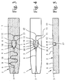
- FIG. 3 shows a second embodiment in a plan view corresponding to FIG. 1 of the sample carrier 1.
- the cover 7 here all cavities 2, including the sample holder 3 and, where appropriate, further sample receptacles 3 and other Cavities 2 of the sample carrier 1, if present.
- Cover 7 in the region of the sample holder 3 pre-scored, perforated, cut, weakened or provided with any other predetermined breaking point.
- the Cover 7 is accordingly partially in the area of the sample holder 3 opened or opened, so that here also a relatively high Evaporation of sample liquid 4 from the sample holder 3 occur can.
- the recorded from the memory 8 sample 4 is subject to contrast a much lower evaporation, so that by means of the memory 8 again - as in the first embodiment - a refilling of Sample liquid 4 in the sample holder 3 even with very long residence times of sample liquid 4 in the sample chambers 6 and / or high Temperatures can be avoided.
- the memory 8 is not chamber-shaped, but by a preferably additional, in particular meandering wound portion 18 of the distribution channel 5 is formed.
- the section 18 at least partially a relative to the distribution channel 5 enlarged cross-section to to achieve a sufficient storage volume, where appropriate, a corresponding capillary force generating device 17 on and / or outlet side is provided or are.
- Figs. 4 and 5 the sample liquid 4 and the cover 7 are off Simplification reasons omitted, wherein Fig. 4 corresponds to Fig. 1 and 3 corresponding Top view shows.
- the memory 8 is connected to the distribution channel 5 parallel to the sample chambers 6.
- the memory 8 after the sample chambers 6 and their feed channels 10 or connected to these at the end of the distribution channel 5 to this in particular so that the memory 8 only after the sample chambers. 6 can be filled with sample liquid 4, to first a fast filling of the sample chambers 6 with sample liquid 4 to allow.
- the memory 8 is again preferable cupped or chamber-like design.
- the memory 8 is or venting via a further connecting channel 19 to the vent collecting channel 12 connected.
- a further connecting channel 19 to the vent collecting channel 12 connected.
- this further Connecting channel 19 and the memory 8 or the vent collecting channel 12 is a liquid stop 14 and / or a liquid seal already formed sense explained in connection with the first embodiment, so that the sample liquid 4 is not from the memory 8 in the vent collecting channel 12 flows or the evaporation of sample liquid. 4 from the memory 8 - even during its emptying - is prevented.
- FIG. 5 of the sample carrier 1 according to FIG. 4 illustrates the structure and the formation of the cavities 2 in the main body 15th
- capillary force generating devices 17 provided, in particular in the memory 8 to the other connection channel 19 out.
- the sample holder 3 is preferably laterally open trained and forms in particular with appropriate Kochdekkung through the cover, not shown, a suction, the sample liquid 4, for example, blood directly from the finger of a person to be examined Person, preferably automatically by capillary forces in the sample carrier 1 can suck.
- the proposed sample carrier 1 is preferably for the particular microbiological diagnostics used, the sample chambers 6 with Sample liquid 4 filled and taking place in the sample chambers 6 reactions and / or related investigations or diagnostic measurements be automatically analyzed or performed, in particular of automated analyzers and / or in particular over several hours, preferably at about 37 ° C, without refilling of sample liquid 4.
Abstract
Description
Die vorliegende Erfindung betrifft einen Probenträger gemäß dem Oberbegriff
des Anspruchs 1 und eine Verwendung des Probenträgers.The present invention relates to a sample carrier according to the preamble
of
Bei einem aus der Praxis bekannten Probenträger sind Probenkammern in einer Grundplatte einseitig eingebracht, also zu einer Flachseite hin offen. Nach dem Befüllen mit Reagenzien werden die Probenkammern insbesondere durch eine Folie abgedeckt. Zur chemischen oder biologischen Diagnostik wird eine Probenflüssigkeit in eine Probenaufnahme mittels einer Pipette eingefüllt oder beispielsweise durch Kapillarkräfte eingesaugt. Die Probenflüssigkeit strömt dann selbsttätig aufgrund von Kapillarkräften über einen Verteilkanal und Zulaufkanäle in die Probenkammern. In den Probenkammern reagiert die Probenflüssigkeit mit den zuvor eingebrachten Reagenzien. Die Reaktionen werden beispielsweise optisch erfaßt.In a sample carrier known from practice sample chambers are in one Base plate introduced on one side, so open to a flat side. To in particular, the sample chambers are filled with reagents covered a foil. For chemical or biological diagnosis is a Sample liquid filled in a sample holder by means of a pipette or sucked in, for example by capillary forces. The sample liquid flows then automatically due to capillary forces via a distribution channel and Inlet channels into the sample chambers. The sample liquid reacts in the sample chambers with the previously introduced reagents. The reactions will be for example, optically detected.
Die in den Probenkammern ablaufenden Reaktionen dauern oft mehrere Stunden und werden oft bei höheren Temperaturen durchgeführt. Die oftmals wäßrigen oder sonstige Lösungsmittel enthaltenden Probenflüssigkeiten unterliegen trotz der Abdeckung - insbesondere aufgrund der offenen bzw. geöffneten Probenaufnahme und einer erforderlichen Entlüftung - einer erheblichen Verdunstung.The reactions taking place in the sample chambers often take several hours and are often done at higher temperatures. The often aqueous or other solvent-containing sample liquids despite the cover - especially due to the open or open Sampling and a required venting - a considerable Evaporation.
Bei hoher Verdunstung ist es daher bisher erforderlich, Probenflüssigkeit in die Probenaufnahme nachzufüllen. Über den damit verbundenen Arbeitsaufwand hinaus besteht hierbei das Risiko, daß zwischenzeitlich Luft einströmen bzw. eingesaugt werden kann.At high evaporation, it is therefore previously required to sample liquid in refill the sample holder. About the associated workload In addition, there is the risk that air will flow in the meantime or can be sucked in.
Alternativ kann die Probenaufnahme auch nach dem ersten Befüllen mit Probenflüssigkeit durch eine zusätzliche Folie wieder verschlossen werden, um die Verdunstung zu minimieren. Jedoch bedeutet dies einen zusätzlichen Arbeits- und damit Zeitaufwand sowie einen zusätzlichen Materialaufwand.Alternatively, the sample holder can also after the first filling with sample liquid be closed again by an additional foil to minimize evaporation. However, this means additional work and thus time and an additional cost of materials.
Der vorliegenden Erfindung liegt die Aufgabe zugrunde, einen Probenträger und dessen Verwendung anzugeben, der auch bei langer Verweilzeit von Probenflüssigkeit im Probenträger, insbesondere lang andauernden Reaktionen, und/oder bei hohen Temperaturen ohne Nachfüllen von Probenflüssigkeit einsetzbar ist, insbesondere wobei ein Abdecken der Probenaufnahme nach dem ersten Applizieren von Probenflüssigkeit nicht erforderlich ist.The present invention is based on the object, a sample carrier and to indicate its use, even with a long residence time of sample liquid in the sample carrier, especially long-lasting reactions, and / or can be used at high temperatures without refilling of sample liquid In particular, wherein covering the sample receptacle after the first application of sample liquid is not required.
Die obige Aufgabe wird durch einen Probenträger gemäß Anspruch 1 oder eine
Verwendung gemäß Anspruch 33 gelöst. Vorteilhafte Weiterbildungen
sind Gegenstand der Unteransprüche.The above object is achieved by a sample carrier according to
Ein Aspekt der vorliegenden Erfindung liegt darin, den Probenträger zusätzlich mit einem abgedeckten Speicher für Probenflüssigkeit zu versehen, so daß bei Verdunstung oder sonstigem Verlust oder Verbrauch von Probenflüssigkeit neue Probenflüssigkeit aus dem Speicher in den Verteilkanal und/oder die Probenkammer(n) nachströmen kann, wobei der Speicher im gefüllten Zustand und während seiner Entleerung über einen Verbindungskanal mit der Umgebung in Verbindung steht, der durch die Probenflüssigkeit oder eine sonstige Flüssigkeit derart verschlossen gehalten wird, um allenfalls ein Einsaugen bzw. Einströmen von der den Probenträger umgebenden Atmosphäre, insbesondere Luft, beim Entleeren des Speichers zu gestatten, jedoch den freien entgegengesetzten Gasaustausch zu begrenzen bzw. zu verhindern.One aspect of the present invention is in addition to the sample carrier provided with a covered storage for sample liquid, so that during evaporation or other loss or consumption of sample liquid new sample liquid from the memory in the distribution channel and / or the sample chamber (s) can flow, the memory in the filled state and during its discharge via a connection channel with the Environment communicating through the sample liquid or a other liquid is kept closed in such a way, if necessary Sucking in or flowing in from the atmosphere surrounding the sample carrier, especially air, to allow the emptying of the memory, however to limit or prevent the free opposite gas exchange.
Ein ansonsten erforderliches Nachfüllen von Probenflüssigkeit in die Probenaufnahme kann durch die genannte, sehr einfach realisierbare Ausbildung vermieden werden, da die freie - also mit der Umgebung in Gasaustausch stehende - Oberfläche der Probenflüssigkeit, von der die Verdunstungsrate maßgeblich abhängt, wesentlich verringert ist. Entsprechend verringert sich die Verdunstung, so daß der vorschlagsgemäße Probenträger auch für sehr lange Verweilzeiten der Probenflüssigkeit in den Probenkammern und/oder bei hohen Temperaturen eingesetzt werden kann, ohne daß ein Nachfüllen von Probenflüssigkeit in die Probenaufnahme erforderlich ist.An otherwise required refilling of sample liquid into the sample holder can by the mentioned, very easy to implement training be avoided, since the free - so with the environment in gas exchange - Surface of the sample liquid, on which the evaporation rate is decisive depends, is substantially reduced. Accordingly, the reduced Evaporation, so that the proposed sample carrier for a very long time Residence times of the sample liquid in the sample chambers and / or at high Temperatures can be used without refilling sample liquid is required in the sample holder.
Vorzugsweise ist im Verbindungskanal ein sich durch Kapillarkräfte selbsttätig schließender Flüssigkeitsverschluß gebildet. Dies ermöglicht bei einfachem Aufbau eine einfache Handhabung. Preferably, in the connecting channel is itself by capillary forces automatically closing liquid closure formed. This allows for easy Construction easy handling.
Der Speicher ist vorzugsweise in Form einer zusätzlichen Kammer ausgebildet. Alternativ oder zusätzlich kann der Speicher auch durch einen verlängerten bzw. zusätzlichen, vorzugsweise gewundenen und/oder im Querschnitt vergrößerten Abschnitt eines Verteilkanals gebildet sein, an den die Probenkammer angeschlossen sind. Dies ermöglicht jeweils einen einfachen, kostengünstigen Aufbau.The memory is preferably in the form of an additional chamber. Alternatively or additionally, the memory may also be extended or additional, preferably tortuous and / or in cross section be formed enlarged portion of a distribution channel to which the sample chamber are connected. This allows a simple, inexpensive each Construction.
Vorzugsweise wird die Probenflüssigkeit auf dem Probenträger ausschließlich durch Kapillarkräfte an die gewünschten Stellen transportiert. Jedoch kann der Transport der Probenflüssigkeit alternativ durch sonstige Mechanismen oder nicht ausschließlich durch Kapillarkräfte erfolgen.Preferably, the sample liquid on the sample carrier is exclusive transported by capillary forces to the desired locations. However, the Transport of the sample liquid alternatively by other mechanisms or not exclusively by capillary forces.
Weitere Vorteile, Merkmale, Eigenschaften und Aspekte der vorliegenden Erfindung ergeben sich aus der folgenden Beschreibung bevorzugter Ausführungsformen anhand der Zeichnung. Es zeigt:
- Fig. 1
- eine schematische, ausschnittsweise Draufsicht eines vorschlagsgemäßen Probenträgers gemäß einer ersten Ausführungsform;
- Fig. 2
- einen Längsschnitt des Probenträgers gemäß Fig. 1;
- Fig. 3
- eine schematische, ausschnittsweise Draufsicht eines vorschlagsgemäßen Probenträgers gemäß einer zweiten Ausführungsform;
- Fig. 4
- eine schematische, ausschnittsweise Draufsicht eines vorschlagsgemäßen Probenträgers gemäß einer dritten Ausführungsform; und
- Fig. 5
- einen Längsschnitt des Probenträgers gemäß Fig. 4.
- Fig. 1
- a schematic, fragmentary plan view of a proposed sample carrier according to a first embodiment;
- Fig. 2
- a longitudinal section of the sample carrier of FIG. 1;
- Fig. 3
- a schematic, fragmentary plan view of a proposed sample carrier according to a second embodiment;
- Fig. 4
- a schematic, fragmentary plan view of a proposed sample carrier according to a third embodiment; and
- Fig. 5
- a longitudinal section of the sample carrier according to FIG. 4th
In den Figuren werden für gleiche oder ähnliche Teile dieselben Bezugszeichen verwendet, wobei entsprechende oder vergleichbare Eigenschaften und Vorteile erreicht werden, auch wenn eine wiederholte Beschreibung weggelassen ist. In the figures, the same reference numerals will be used for the same or similar parts used, with corresponding or comparable properties and Benefits can be achieved even if a repeated description is omitted is.
Fig. 1 zeigt in einer schematischen, ausschnittsweisen Draufsicht eine erste
Ausführungsform eines vorschlagsgemäßen Probenträgers 1 - auch Mikrotiterplatte
genannt - mit Kavitäten 2 im µl-Bereich, nämlich mindestens einer
Probenaufnahme 3 für Probenflüssigkeit 4 und vorzugsweise mehreren über
einen gemeinsamen Verteilkanal 5 an die Probenaufnahme 3 angeschlossenen
Probenkammern 6. Der Probenträger 1 kann mehrere Probenaufnahmen 3 mit
jeweils mindestens einem daran angeschlossenen Verteilkanal 5 und zugeordneten
Probenkammern 6 aufweisen.Fig. 1 shows a schematic, partial plan view of a first
Embodiment of a proposed sample carrier 1 - also microtiter plate
called - with
Bei der ersten Ausführungsform sind die Kavitäten 2 mit Ausnahme der Probenaufnahme
3 von einer insbesondere folienartigen Abdeckung 7 überdeckt,
vorzugsweise oberseitig abgeschlossen. So wird ein zumindest im wesentlichen
geschlossenes bzw. weitgehend gegen Verdunstung geschütztes Leitungssystem
für die Probenflüssigkeit 4 gebildet.In the first embodiment, the cavities are 2 except for the
Bei der Darstellung gemäß Fig. 1 ist Probenflüssigkeit 4 bereits in die Probenaufnahme
3 gefüllt bzw. appliziert, jedoch noch nicht in die angeschlossenen
Kavitäten 2 geströmt. Das Einfüllen von Probenflüssigkeit 4 ist bei dem ersten
Ausführungsbeispiel problemlos möglich, da die Probenaufnahme 3 nach
oben hin offen ist, zumal sie von der Abdeckung 7 nicht oder gegebenenfalls
nur teilweise abgedeckt ist. Bedarfsweise ist die Probenaufnahme 3 seitlich
geschlossen, insbesondere näpfchen- bzw. kammerartig ausgebildet.In the illustration according to FIG. 1,
Der Probenträger 1 weist vorschlagsgemäß zusätzlich einen Speicher 8 auf,
der bei der ersten Ausführungsform einlaufseitig über einen Verbindungskanal
9 an die Probenaufnahme 3 und auslaufseitig an den Verteilkanal 5 angeschlossen
ist. Der Speicher 8 ist hier näpfchen- bzw. kammerartig ausgebildet
und ebenfalls von der Abdeckung 7 abgedeckt.The
Nach dem Einfüllen kann die Probenflüssigkeit 4 durch den Verbindungskanal
9, den Speicher 8, den Verteilkanal 5 und über daran angeschlossene Zulaufkanäle
10 in die Probenkammern 6 strömen. Dies erfolgt vorzugsweise
selbsttätig durch Kapillarkräfte.After filling, the
An die Probenkammern 6 schließen sich Entlüftungskanäle 11 an, die ihrerseits
- insbesondere über einen im Querschnitt vergrößerten Verbindungsabschnitt
und/oder einen Entlüftungssammelkanal 12 - in eine nach außen hin
offene Entlüftungsöffnung 13 münden, um die von der einströmenden Probenflüssigkeit
4 verdrängte Luft oder sonstige Atmosphäre aus dem Leitungssystem
abzuleiten.At the
Fig. 2 zeigt einen schematischen Längsschnitt des Probenträgers 1 gemäß Fig.
1 entlang Kanälen 9, 5, 10, 11 und 12, jedoch in einem Zustand, in dem die
Probenflüssigkeit 4 aus der Probenaufnahme 3 in die angeschlossenen Kavitäten
2 geströmt ist.FIG. 2 shows a schematic longitudinal section of the
Die Probenflüssigkeit 4 strömt beim Darstellungsbeispiel vorzugsweise nicht
aus den Probenkammern 6 in die Entlüftungskanäle 11, da insbesondere aufgrund
entsprechender Ausbildung oder Querschnittsunterschiede jeweils ein
sogenannter Flüssigkeitsstop 14 gebildet ist. Durch Kapillarkräfte und/oder
Schwerkraft wird die Probenflüssigkeit 4 daran gehindert, in die Entlüftungskanäle
11 zu fließen.The
Jedoch können die Flüssigkeitsstops 14 auch erst am Übergang der Entlüftungskanäle
11 in den Entlüftungssammelkanal 12 - insbesondere durch den
im Querschnitt vergrößerten Verbindungsabschnitt - gebildet sein, wie in Fig.
2 angedeutet.However, the liquid stops 14 can only at the transition of the venting
Alternativ oder zusätzlich zu den Flüssigkeitsstops 14 können auch nicht dargestellte
Ventile oder sonstige geeignete Einrichtungen zur Manipulation der
Probenflüssigkeit 4 eingesetzt werden.Alternatively or in addition to the liquid stops 14 may also not shown
Valves or other suitable means for manipulating the
Alternativ oder zusätzlich zu der allein durch Kapillarkraft bewirkten Füllung
der an die Probenaufnahme 3 angeschlossenen sonstigen Kavitäten 2 mit Probenflüssigkeit
4 aus der Probenaufnahme 3 kann die Probenflüssigkeit 4 auch
gepumpt, gesaugt oder durch sonstige Effekte gefördert werden.Alternatively or in addition to the fill caused solely by capillary force
the connected to the
Vorzugsweise sind alle Kavitäten 2 in einem Grundkörper 15 des Probenträgers
1 gebildet. Insbesondere sind alle Kavitäten 2 ausgehend von einer Flachseite
16 des Grundkörpers 15 und zur Flachseite 16 hin offen, beispielsweise
durch Näpfchen, Rillen, Nuten, Ausnehmungen oder dergleichen, gebildet. Preferably, all
Die Abdeckung 7 ist auf den Grundkörper 15 bzw. dessen Flachseite 16 aufgeklebt,
aufkaschiert oder in sonstiger Weise aufgebracht und überdeckt alle
Kavitäten 2 - bei der ersten Ausführungsform mit Ausnahme der Probenaufnahme
3 - des Probenträgers 1, so daß die Kavitäten 2 auch nach oben hin abgeschlossen
sind, wie in Fig. 1 und 2 angedeutet. Beim Darstellungsbeispiel
ist der Probenträger 1 also vorzugsweise zweiteilig ausgebildet.The
Alternativ kann der Probenträger 1 auch einteilig ausgebildet sein oder mehrere,
gegebenenfalls getrennt aufbringbare Abdeckungen 7 aufweisen.Alternatively, the
Anstelle der bevorzugten folienartigen Ausbildung der Abdeckung 7 kann
diese beispielsweise durch eine Glasplatte oder sonstiges geeignetes Material
mit geeigneten Eigenschaften bei geeigneter Formgebung gebildet sein.Instead of the preferred film-like design of the
Hinsichtlich des Grundkörpers 15 und der Abdeckung 7 ist anzumerken, daß
ein für die gewünschten Benetzungseigenschaften - zumindest im Bereich des
Verbindungskanals 9 und/oder der Flüssigkeitsstops 14 - geeignetes und/oder
gegebenenfalls auch nur bereichsweise modifiziertes oder modifizierbares,
beispielsweise zumindest partiell hydrophil für wäßrige Lösungsmittel bzw.
Probenflüssigkeiten 4 oder hydrophob für lippophile Lösungsmittel bzw. Probenflüssigkeiten
4 beschichtetes, Material, insbesondere Kunststoff, vorzugsweise
verwendet wird. Vorzugsweise wird durch Plasmapolymerisation eine
gute Benetzbarkeit erreicht.With regard to the
In den Probenkammern 6 können nach dem Einströmen von Probenflüssigkeit
4 Messungen, Manipulationen, Untersuchungen oder Reaktionen, beispielsweise
zur biologischen, insbesondere mikrobiologischen, oder chemischen
Diagnostik, stattfinden, insbesondere mit bzw. durch in den Probenkammern 6
befindlichen, nicht dargestellten Reagenzien oder durch sonstige Einwirkung.
Vorzugsweise werden die Reagenzien vor Aufbringen der Abdeckung 7 in die
Probenkammern 6 eingebracht. Um die Untersuchungen oder Reaktionen vorzugsweise
optisch - beispielsweise durch Transmissions-, Fluoreszenz- oder
Trübungsmessungen - durchführen bzw. verfolgen zu können, ist bzw. sind
die Abdeckung 7 und/oder der Grundkörper 15 vorzugsweise aus ausreichend
transparentem Material hergestellt oder vorzugsweise zumindest bereichsweise,
insbesondere oberhalb und/oder unterhalb der Probenkammern 6, transparent
ausgebildet.In the
Gerade bei mehreren Stunden dauernden Untersuchungen, Manipulationen
und/oder Reaktionen und/oder bei hohen Reaktions- bzw. Umgebungstemperaturen
von beispielsweise 37°C, bei denen insbesondere mikrobiologische
Reaktionen oftmals ablaufen, und/oder bei verhältnismäßig geringer Luftfeuchtigkeit
ist die Verdunstung von Probenflüssigkeit 4 trotz der Abdeckung
7 erheblich. Insbesondere stehen alle Probenkammern 6 über die erforderliche
Entlüftung - Entlüftungskanäle 11 und Entlüftungssammelkanal 12 - mit der
Umgebung in Verbindung.Especially with several hours of investigations, manipulations
and / or reactions and / or at high reaction or ambient temperatures
for example, 37 ° C, in particular microbiological
Reactions often occur, and / or at relatively low humidity
is the evaporation of
Des weiteren kann Probenflüssigkeit 4 aus der Probenaufnahme 3 ungehindert
verdunsten, insbesondere wenn, wie bisher üblich, kein Speicher 8 vorgesehen
ist und Probenflüssigkeit 4 als Verdunstungsreservoir in der Probenaufnahme
3 nach dem Füllen der Probenkammern 6 noch vorhanden ist.Furthermore, sample liquid 4 from the
Die Verdunstung führt dazu, daß ein Nachfüllen von Probenflüssigkeit 4 in
die Probenaufnahme 3 üblicherweise erforderlich ist. Hierbei besteht das Risiko,
daß bei nicht rechtzeitigem Nachfüllen Luft in das Leitungssystem, insbesondere
den Verteilkanal 5 und die sich anschließenden Probenkammern 6
eindringt, was zu unerwünschten bzw. unbrauchbaren Ergebnissen oder Reaktionen,
insbesondere in den Probenkammern 6, führen kann.The evaporation causes a refilling of
Vorschlagsgemäß weist der Probenträger 1 zusätzlich den Speicher 8 für Probenflüssigkeit
4 auf. Bei Verdunstung oder sonstigem Verlust oder Verbrauch
von Probenflüssigkeit 4 kann dementsprechend neue Probenflüssigkeit 4 aus
dem Speicher 8 in den Verteilkanal 5 und in die Probenkammern 6 nachströmen
und/oder in den Verbindungskanal 9 zurückströmen.According to the proposal, the
Bei der ersten Ausführungsform ist der Speicher 8 aufgrund seiner Anordnung
- seriell zwischen der Probenaufnahme 3 und den Probenkammern 6 - nur vor
den Probenkammern 6 mit Probenflüssigkeit 4 füllbar.In the first embodiment, the
Der vorschlagsgemäße Probenträger 1 ist vorzugsweise derart - insbesondere
durch entsprechende Wahl der Querschnitte der Kanäle 5, 10, 11, 9 und/oder
entsprechende Ausbildung der Übergänge zwischen diesen und den Kammern
3, 6, 8 - ausgebildet, daß ausgehend von dem mit Probenflüssigkeit 4 gefüllten
Zustand - also gefüllten Probenkammern 6 - bei Verdunstung oder sonstigem
Verlust oder Verbrauch von Probenflüssigkeit 4 eine Entleerung zunächst
der Probenaufnahme 3 erfolgt, sofern dies zu diesem Zeitpunkt noch nicht geschehen
ist, und dann des Speichers 8 sowie anschließend des Verteilkanals 5
und der Zulaufkanäle 10, insbesondere so daß bis zu dieser Entleerung die
Probenkammern 6 mit Probenflüssigkeit 4 gefüllt bleiben. Dies kann insbesondere
dadurch erreicht werden, daß durch entsprechend hohe Kapillarkräfte
und/oder nicht dargestellte Ventile ein Zurückweichen der Probenflüssigkeit 4
aus den Probenkammern 6 bzw. von den Flüssigkeitsstops 14 während des
vorgenannten Entleervorgangs verhindert wird.The proposed
Aufgrund der Überdeckung des Speichers 8 durch die Abdeckung 7 ist nach
dem Einströmen der Probenflüssigkeit 4 aus der Probenaufnahme 3 in die angeschlossenen
Kavitäten 2 einschließlich des Speichers 8 die Verdunstung
von Probenflüssigkeit 4 wesentlich reduziert, da der Speicher 8 lediglich über
den verhältnismäßig kleinen Querschnitt des Verbindungskanals 9 mit der
Umgebung in Verbindung steht.Due to the overlap of the
Der Probenträger 1 ist derart ausgebildet, daß immer - auch während des
Entleerens des Speichers 8 - Probenflüssigkeit 4 im Verbindungskanal 9 steht
oder in diesen durch Kapillarkräfte gezogen wird, so daß der Verbindungskanal
9 zumindest temporär bzw. zumindest im wesentlichen ständig von Probenflüssigkeit
4 verschlossen gehalten wird, wie in Fig. 2 angedeutet. Der
Verschluß des Verbindungskanals 9 durch Probenflüssigkeit 4 kann auch dadurch
erfolgen, daß Probenflüssigkeit 4 nur die in den Speicher 8 mündende
Zulauföffnung des Verbindungskanals 9 - den Verbindungskanal 9 also nur
speicherseitig - verschließt. Vorzugsweise bleibt der Verbindungskanal 9 bis
zum einlaßseitigen Ende - also bis zur Öffnung zur Probenaufnahme 3 hin,
insbesondere bis zu einem dort gebildeten Flüssigkeitsstop 14 - mit Probenflüssigkeit
4 gefüllt bzw. selbsttätig vom Speicher 8 aus wieder füllbar. Der so
gebildete Flüssigkeitsverschluß bewirkt, daß Umgebungsatmosphäre durch
den Verbindungskanal 9 in den Speicher nur hineinströmen oder eingesaugt
werden kann und und ein sonstiger Gasaustausch zwischen der Oberfläche O
der Probenflüssigkeit 4 im Speicher 8 und der Umgebung verhindert wird. The
Damit Probenflüssigkeit 4 auch bei fallendem Pegel in Speicher 8 - also Entleerung
des Speichers 8 - zum Verbindungskanal 9 aufsteigen und diesen verschließen
kann, ist vorzugsweise eine - später detaillierter erläuterte - Kapillarkraft-Erzeugungseinrichtung
17 vorgesehen, die Probenflüssigkeit 4 aus
dem Speicher 8 zum Verbindungskanal 9 aufsteigen läßt. Der Probenträger 1
ist dann derart ausgebildet, daß immer Probenflüssigkeit 4 aus dem Speicher 8
zu dem Verbindungskanal 9 hin bzw. in diesen gezogen wird, solange noch
Probenflüssigkeit 4 im Speicher 8 vorhanden ist.So that
Alternativ kann sich grundsätzlich auch eine Probenflüssigkeitsmenge von der
im Speicher 8 befindlichen Probenflüssigkeit 4 trennen und den gewünschten
Verschluß des Verbindungskanals 9 erzeugen, wobei dann vorzugsweise ein
weiterer, nicht dargestellter Speicher für Probenflüssigkeit 4 dem Verbindungskanal
9 zum Ausgleich von Verdunstungsverlusten und Aufrechterhaltung
des Flüssigkeitsverschlusses zugeordnet ist.Alternatively, in principle, a sample liquid amount of the
Separate in the
Der Verschluß des Verbindungskanals 9 durch Probenflüssigkeit 4 führt dazu,
daß lediglich die Flüssigkeitsoberfläche im Verbindungskanal 9, jedoch nicht
die gesamte Oberfläche O der Probenflüssigkeit 4 im Speicher 8 bzw. dessen
Grundfläche, die insbesondere um den Faktor 10, 100 oder sogar 1000 größer
als die Querschnittsfläche des Verbindungskanals 9 ist bzw. sind, mit der
Umgebung im Gasaustausch steht und daher der Verdunstung unterliegt.
Dementsprechend führt der Flüssigkeitsverschluß zu einer wesentlich reduzierten
Verdunstung, da die Oberfläche O der Probenflüssigkeit 4 im Speicher
8 nicht mit der Umgebung in Gasaustausch steht.The closure of the
Beim Entleeren des Speichers 8 bleibt der Flüssigkeitsverschluß zumindest im
wesentlichen ständig erhalten und läßt bei entsprechendem Unterdruck im
Speicher 8 lediglich (kurzzeitig) Umgebungsatmosphäre bzw. Luft in den
Speicher 8 zum Belüften bzw. Druckausgleich strömen. Durch Kapillarkraft:
erfolgt dann wieder ein sofortiges Schließen. Der Flüssigkeitsverschluß wirkt
dementsprechend als Einwegventil und verhindert oder hemmt zumindest den
Gasaustausch zwischen dem Speicher 8 und der Umgebung. When emptying the
Der Flüssigkeitsverschluß stellt eine besonders bevorzugte, einfache und kostengünstig
zu realisierende Lösung dar. Bedarfsweise kann statt Probenflüssigkeit
4 auch eine sonstige Flüssigkeit, beispielsweise eine Steuerflüssigkeit,
eingesetzt werden. Dies ist insbesondere dann vorteilhaft, wenn nur wenig
bzw. nicht ausreichend viel Probenflüssigkeit 4 zur Verfügung steht. Alternativ
oder zusätzlich kann statt eines Flüssigkeitsverschlusses auch ein sonstiges
Ventil, insbesondere ein geeignetes Einwegventil, verwendet werden.The liquid closure provides a particularly preferred, simple and inexpensive
to be implemented solution. If necessary, instead of
Gemäß einer die Verdunstung besonders minimierenden Variante weist der
Speicher 8 eine kleinere Öffnungsfläche zur Zuführung von Probenflüssigkeit
4 und/oder zur Be- bzw. Entlüftung, insbesondere im Bereich eines Flüssigkeitsstops
14, als der Verteilkanal 5 auf.According to a particularly minimizing the evaporation variant has the
Durch entsprechende Dimensionierung des Speichers 8 ist es daher möglich,
auch bei langen Reaktionsdauem und/oder hohen Temperaturen den Probenträger
1 ohne Nachfüllen von Probenflüssigkeit 4 in die Probenaufnahme 3
einzusetzen.By appropriate dimensioning of the
Vorzugsweise beträgt das Aufnahmevolumen des Speichers 8 für Probenflüssigkeit
4 mindestens 5%, vorzugsweise mindestens 10%, insbesondere mindestens
20%, des Aufnahmevolumens der angeschlossenen, Probenflüssigkeit 4
aufnehmenden Kavitäten 2, der Probenaufnahme 3 und/oder aller angeschlossenen
Probenkammern 6.Preferably, the receiving volume of the
Vorzugsweise ist das Aufnahmevolumen der Probenaufnahme 3 im wesentlichen
gleich der oder kleiner als die Summe der Aufnahmevolumina der angeschlossenen
Kavitäten 2, insbesondere des Verteilkanals 5, des Verbindungskanals
9, des Speichers 8, der Probenkammern 6 und/oder der Zulaufkanäle
10 und/oder gegebenenfalls der Entlüftungskanäle 11, insbesondere so daß
nach dem Füllen der Probenaufnahme 3 mit Probenflüssigkeit 4 diese Füllmenge
unmittelbar von den angeschlossenen Kavitäten 2 aufgenommen wird,
und zwar vorzugsweise selbsttätig durch Kapillarkräfte, wie bereits erwähnt.Preferably, the receiving volume of the
Entsprechend strömt die Probenflüssigkeit 4 aus dem Speicher 8 vorzugsweise
selbsttätig, insbesondere durch Kapillarkräfte, in nachgeordnete bzw. angeschlossene,
Probenflüssigkeit 4 aufnehmende Kavitäten 2, wie den Verteilkanal
5, die Zulaufkanäle 10 und die Probenkammern 6 sowie ggf. die Entlüftungskanäle
11.Accordingly, the
Wie bereits erläutert, ist der Speicher 8 vorzugsweise nur zeitlich nach der
Probenaufnahme 3 entleerbar. Weiter ist bzw. sind der Verteilkanal 5 und/oder
die Zulaufkanäle 10 vorzugsweise nur nach dem Speicher 8 entleerbar.As already explained, the
Beim Darstellungsbeispiel ist jeder Probenaufnahme 3 und/oder jedem Verteilkanal
5 vorzugsweise nur ein einziger Speicher 8 zugeordnet. Vorzugsweise
ist also allen an den gleichen Verteilkanal 5 angeschlossenen Probenkammern
6 Probenflüssigkeit 4 aus dem gleichen Speicher 8 zuführbar.In the illustrated example, each sample receptacle is 3 and / or each
Jedoch können alternativ oder zusätzlich auch weitere Speicher 8 vorgesehen
sein, so daß die Probenkammern 6 gruppen- oder einzelweise den Speichern 8
zugeordnet sein können.However, alternatively or additionally,
Vorzugsweise sind die Probenkammern 6 fluidisch zwischen dem Speicher 8
und den nachgeordneten Flüssigkeitsstops 14 oder beispielsweise nicht dargestellten
Ventilen angeordnet.Preferably, the
Um die erforderlichen Kapillarkräfte zu erzeugen, die die gewünschte Strömung
der Probenflüssigkeit 4 bewirken, weisen die Probenaufnahme 3 und
der Speicher 8 sowie gegebenenfalls die Probenkammern 6 vorzugsweise jeweils
Kapillarkraft-Erzeugungseinrichtungen 17 im Bereich ihrer vertikalen
Wandungen auf. Diese Kapillarkraft-Erzeugungseinrichtungen 17 weisen vorzugsweise
jeweils eine vertikale Rille oder Keilnut mit einem derartigen
Keilwinkel auf, daß die Probenflüssigkeit 4 durch Kapillarkräfte ab- oder aufsteigen
und in den Verbindungskanal 9, den Verteilkanal 5 und/oder gegebenenfalls
in die Entlüftungskanäle 11 strömen kann.To generate the required capillary forces, the desired flow
cause the
Zur Ausbildung der Kapillarkraft-Erzeugungseinrichtung(en) 17 als keilförmige
Aussparung wird alternativ oder ergänzend auf die EP 1 013 341 A2
verwiesen, die hiermit voll umfänglich als ergänzende Offenbarung eingeführt
wird. To form the capillary force generating device (s) 17 as wedge-shaped
Recess is alternatively or additionally to
Insbesondere ist jeweils eine Kapillarkraft-Erzeugungseinrichtung 17 in der
Probenaufnahme 3 zum Verbindungskanal 9 hin, von diesem in den Speicher
8, im Speicher 8 zum Verteilkanal 5 hin, von dem Zulaufkanälen 10 in die
Probenkammern 6 und gegebenenfalls von diesen in die Entlüftungskanäle 11
vorgesehen.In particular, each capillary
Nachfolgend werden weitere Ausführungsbeispiele anhand der weiteren Figuren erläutert. Hierbei wird jeweils nur auf wesentliche Unterschiede gegenüber der ersten Ausführungsform eingegangen. Die vorgenannten Erläuterungen gelten für diese weiteren Ausführungsformen ansonsten entsprechend.Below are further embodiments with reference to the other figures explained. This is only compared to significant differences of the first embodiment. The above explanations otherwise apply mutatis mutandis to these further embodiments.
Fig. 3 zeigt in einer zu Fig. 1 korrespondierenden Draufsicht eine zweite Ausführungsform
des Probenträgers 1. Im Unterscheid zur ersten Ausführungsform
überdeckt die Abdeckung 7 hier alle Kavitäten 2, also auch die Probenaufnahme
3 und gegebenenfalls auch weitere Probenaufnahmen 3 und sonstigen
Kavitäten 2 des Probenträgers 1, sofern vorhanden.FIG. 3 shows a second embodiment in a plan view corresponding to FIG. 1
of the
Um ein Befüllen der Probenaufnahme 3 mit Probenflüssigkeit 4, insbesondere
mittels einer nicht dargestellten Pipette oder dergleichen, zu erleichtern, ist die
Abdeckung 7 im Bereich der Probenaufnahme 3 vorgeritzt, perforiert, eingeschnitten,
geschwächt oder mit einer sonstigen Sollbruchstelle versehen. Die
Abdeckung 7 ist dementsprechend im Bereich der Probenaufnahme 3 teilweise
geöffnet oder öffenbar, so daß auch hier eine noch verhältnismäßig hohe
Verdunstung von Probenflüssigkeit 4 aus der Probenaufnahme 3 auftreten
kann. Die vom Speicher 8 aufgenommene Probenflüssigkeit 4 unterliegt demgegenüber
einer wesentlich geringeren Verdunstung, so daß mittels des Speichers
8 wiederum - wie bei der ersten Ausführungsform - ein Nachfüllen von
Probenflüssigkeit 4 in die Probenaufnahme 3 auch bei sehr langen Verweilzeiten
von Probenflüssigkeit 4 in den Probenkammern 6 und/oder hohen
Temperaturen vermieden werden kann.To fill the
Bei der zweiten Ausführungsform ist der Speicher 8 nicht kammerförmig ausgebildet,
sondern durch einen vorzugsweise zusätzlichen, insbesondere mäanderförmig
gewundenen Abschnitt 18 des Verteilkanals 5 gebildet. In the second embodiment, the
Alternativ oder zusätzlich kann der Abschnitt 18 zumindest bereichsweise einen
gegenüber dem Verteilkanal 5 vergrößerten Querschnitt aufweisen, um
ein ausreichendes Speichervolumen zu erreichen, wobei gegebenenfalls eine
entsprechende Kapillarkraft-Erzeugungseinrichtung 17 ein- und/oder auslaufseitig
vorgesehen ist bzw. sind.Alternatively or additionally, the
Auch bei der zweiten Ausführungsform ist wiederum ein Flüssigkeitsverschluß
des Verbindungskanals 9 im bereits erläuterten Sinne vorgesehen.Also in the second embodiment is again a liquid closure
the connecting
In den Fig. 4 und 5 sind die Probenflüssigkeit 4 und die Abdeckung 7 aus
Vereinfachungsgründen weggelassen, wobei Fig. 4 eine zu Fig. 1 und 3 korrespondierende
Draufsicht zeigt.In Figs. 4 and 5, the
Fig. 4 zeigt eine dritte Ausführungsform des Probenträgers 1. Der Speicher 8
ist parallel zu den Probenkammern 6 an den Verteilkanal 5 angeschlossen.
Insbesondere ist der Speicher 8 nach den Probenkammern 6 bzw. deren Zulaufkanälen
10 oder mit diesen am Ende des Verteilkanals 5 an diesen angeschlossen,
insbesondere so daß der Speicher 8 nur nach den Probenkammern 6
mit Probenflüssigkeit 4 füllbar ist, um zunächst ein schnelles Füllen der Probenkammern
6 mit Probenflüssigkeit 4 zu ermöglichen.4 shows a third embodiment of the
Bei der dritten Ausführungsform ist der Speicher 8 wiederum vorzugsweise
näpfchen- bzw. kammerartig ausgebildet. Zusätzlich ist der Speicher 8 zur Be-
bzw. Entlüftung über einen weiteren Verbindungskanal 19 an den Entlüftungssammelkanal
12 angeschlossen. Vorzugsweise zwischen diesem weiteren
Verbindungskanal 19 und dem Speicher 8 oder dem Entlüftungssammelkanal
12 ist ein Flüssigkeitsstop 14 und/oder ein Flüssigkeitsverschluß im bereits
im Zusammenhang mit der ersten Ausführungsform erläuterten Sinn gebildet,
so daß die Probenflüssigkeit 4 nicht aus dem Speicher 8 in den Entlüftungssammelkanal
12 strömt bzw. die Verdunstung von Probenflüssigkeit 4
aus dem Speicher 8 - auch während dessen Entleerung - verhindert wird.In the third embodiment, the
Die Kapillarkräfte im Bereich dieses Flüssigkeitsstops 14 bzw. in diesem
Verbindungskanal 19 und/oder im Speicher 8 sind wiederum derart an die
sonstigen mit Probenflüssigkeit 4 gefüllten bzw. füllbaren Kavitäten 2 angepaßt,
daß bei Verdunstung oder sonstigem Verlust oder Verbrauch von Probenflüssigkeit
4 neue Probenflüssigkeit 4 aus dem Speicher 8 in diese Kavitäten
2, insbesondere in den Verteilkanal 5, die Zulaufkanäle 10, die Probenkammem
6 und/oder gegebenenfalls die an die Probenkammern 6 angeschlossenen
Entlüftungskanäle 11 zurück- bzw. nachströmt, ohne daß der Flüssigkeitsverschluß
des weiteren Verbindungskanals 19 durch Probenflüssigkeit 4
einen Gasaustausch des sich leerenden Speichers 8 mit der Umgebung außer
einem Ansaugen von Umgebungsatmosphäre bzw. Luft zum Druckausgleich
gestattet.The capillary forces in the region of this
Der Längsschnitt von Fig. 5 des Probenträgers 1 gemäß Fig. 4 veranschaulicht
den Aufbau bzw. die Ausbildung der Kavitäten 2 im Grundkörper 15.The longitudinal section of FIG. 5 of the
Bei der dritten Ausführungsform sind wiederum an den entsprechenden Übergängen,
soweit gewünscht bzw. erforderlich, Kapillarkraft-Erzeugungseinrichtungen
17 vorgesehen, insbesondere auch im Speicher 8 zum weiteren Verbindungskanal
19 hin.In the third embodiment, again at the respective transitions,
if desired or required, capillary
Bei der dritten Ausführungsform ist die Probenaufnahme 3 vorzugsweise seitlich
offen ausgebildet und bildet insbesondere bei entsprechender Überdekkung
durch die nicht dargestellte Abdeckung einen Ansaugbereich, der Probenflüssigkeit
4, beispielsweise Blut unmittelbar vom Finger einer zu untersuchenden
Person, vorzugsweise selbsttätig durch Kapillarkräfte in den Probenträger
1 saugen kann.In the third embodiment, the
Selbstverständlich können alle Ausführungsformen je nach Bedarf miteinander kombiniert und auch beliebige oder gleiche Ausführungsformen von Speicher-Verteilkanal-Kombinationen zusammen eingesetzt werden.Of course, all embodiments as needed with each other combined and also any or the same embodiments of memory distribution channel combinations be used together.
Versuche mit einem Probenträger 1 bei einer Temperatur von 37°C ± 1°C und
einer relativen Luftfeuchtigkeit von ungefähr 30% haben beispielsweise gezeigt,
daß bei anfänglicher Dosierung von einer Einfüllmenge x an Probenflüssigkeit
4 in die Probenaufnahme 3 ein Nachfüllen nach 1,0 h ohne Speicher
8, nach mehr als 3,0 h bei einem Speicher 8 mit einem Aufnahmevolumen
von etwa x/10 und sogar erst nach mehr als 6,0 h bei einem Speicher 8
mit einem Aufnahmevolumen von etwa x/5 erforderlich war. Diese Versuche
belegen die überraschend hohe Wirksamkeit des vorschlagsgemäßen Speichers
8.Experiments with a
Der vorschlagsgemäße Probenträger 1 wird vorzugsweise für die insbesondere
mikrobiologische Diagnostik eingesetzt, wobei die Probenkammern 6 mit
Probenflüssigkeit 4 gefüllt und in den Probenkammern 6 erfolgende Reaktionen
und/oder diesbezügliche Untersuchungen bzw. Messungen zur Diagnostik
automatisiert analysiert bzw. durchgeführt werden, insbesondere von Analyseautomaten
und/oder insbesondere über mehrere Stunden, vorzugsweise bei
etwa 37°C, ohne Nachfüllen von Probenflüssigkeit 4.The proposed
Claims (33)
dadurch gekennzeichnet, daß der Probenträger (1) zusätzlich einen Speicher (8) für Probenflüssigkeit (4) aufweist, der von der Abdeckung (7) abgedeckt ist und über einen Verbindungskanal (9, 19) mit der Umgebung in Verbindung steht, wobei der Probenträger (1) derart ausgebildet ist, daß bei Verdunstung oder sonstigem Verlust oder Verbrauch Probenflüssigkeit (4) aus dem Speicher (8) in den Verteilkanal (5) und/oder die Probenkammer (6) nachströmt und daß der Verbindungskanal (9, 19) bei gefülltem Speicher (8) und während der Entleerung des Speichers (8) selbsttätig durch die Probenflüssigkeit (4) oder eine sonstige Flüssigkeit derart verschlossen gehalten wird, daß Umgebungsatmosphäre durch den Verbindungskanal (9, 19) in den Speicher (8) nur hineinströmen oder eingesaugt werden kann.Sample carrier (1) having a plurality of cavities (2), namely at least one sample holder (3) for sample liquid (4) and at least one sample chamber (6), in particular via a distribution channel (5) to the sample holder (3), and with a cover (7) covering the sample chamber (6) and optionally the distribution channel (5),
characterized in that the sample carrier (1) additionally has a reservoir (8) for sample liquid (4) which is covered by the cover (7) and communicates with the environment via a connection channel (9, 19), the sample carrier (1) is designed such that at evaporation or other loss or consumption sample liquid (4) from the memory (8) in the distribution channel (5) and / or the sample chamber (6) flows and that the connecting channel (9, 19) at filled memory (8) and during the emptying of the memory (8) automatically kept closed by the sample liquid (4) or other liquid such that ambient atmosphere through the connecting channel (9, 19) in the memory (8) only to flow or sucked can be.
Applications Claiming Priority (2)
| Application Number | Priority Date | Filing Date | Title |
|---|---|---|---|
| DE10354806 | 2003-11-21 | ||
| DE10354806A DE10354806A1 (en) | 2003-11-21 | 2003-11-21 | sample carrier |
Publications (1)
| Publication Number | Publication Date |
|---|---|
| EP1533035A1 true EP1533035A1 (en) | 2005-05-25 |
Family
ID=34428878
Family Applications (1)
| Application Number | Title | Priority Date | Filing Date |
|---|---|---|---|
| EP04026639A Withdrawn EP1533035A1 (en) | 2003-11-21 | 2004-11-10 | Sample carrier |
Country Status (5)
| Country | Link |
|---|---|
| US (1) | US7829027B2 (en) |
| EP (1) | EP1533035A1 (en) |
| JP (1) | JP4921706B2 (en) |
| CN (1) | CN1664543B (en) |
| DE (1) | DE10354806A1 (en) |
Cited By (2)
| Publication number | Priority date | Publication date | Assignee | Title |
|---|---|---|---|---|
| DE102006025477A1 (en) * | 2006-05-30 | 2007-12-06 | Ekf - Diagnostic Gmbh | cuvette |
| WO2008128534A1 (en) * | 2007-04-24 | 2008-10-30 | Analytik Jena Ag | Cuvette for optical analysis of small volumes |
Families Citing this family (11)
| Publication number | Priority date | Publication date | Assignee | Title |
|---|---|---|---|---|
| DE102005054923B3 (en) | 2005-11-17 | 2007-04-12 | Siemens Ag | Device for preparing a sample used in biotechnology stores the working reagents in dry form embedded in a biologically degradable medium which is water-tight in the non-degraded state |
| SI1948798T1 (en) * | 2005-11-18 | 2015-09-30 | Glenmark Pharmaceuticals S.A. | Anti-alpha2 integrin antibodies and their uses |
| KR100878229B1 (en) * | 2007-11-22 | 2009-01-12 | 주식회사 디지탈바이오테크놀러지 | Chip for analysis of fluidic liquid |
| US8511889B2 (en) * | 2010-02-08 | 2013-08-20 | Agilent Technologies, Inc. | Flow distribution mixer |
| JP2014503426A (en) * | 2010-11-10 | 2014-02-13 | ベーリンガー インゲルハイム マイクロパーツ ゲゼルシャフト ミット ベシュレンクテル ハフツング | Method of filling blister packaging material with liquid and blister packaging material with cavity for filling liquid |
| CN102350379A (en) * | 2011-07-04 | 2012-02-15 | 大连理工大学 | Micro fluid control whole blood preprocessing chip based on naturally-deposited filling column |
| JP6108499B2 (en) | 2012-05-11 | 2017-04-05 | コーニンクレッカ フィリップス エヌ ヴェKoninklijke Philips N.V. | Method for imaging specular object and target anatomy in tissue using ultrasound and ultrasound imaging apparatus |
| WO2014083496A1 (en) | 2012-11-29 | 2014-06-05 | Koninklijke Philips N.V. | Cartridge for uptake and processing of a sample |
| JP6312440B2 (en) * | 2013-04-03 | 2018-04-18 | 日精株式会社 | Capillary blood collection tool |
| JP2015223562A (en) * | 2014-05-28 | 2015-12-14 | 国立大学法人お茶の水女子大学 | Minute-amount liquid transfer device |
| US20200064254A1 (en) * | 2018-08-23 | 2020-02-27 | Truvian Sciences, Inc. | Devices With Optically Readable Liquid Reservoirs |
Citations (8)
| Publication number | Priority date | Publication date | Assignee | Title |
|---|---|---|---|---|
| EP0430248A2 (en) * | 1989-11-30 | 1991-06-05 | Mochida Pharmaceutical Co., Ltd. | Reaction vessel |
| US5192693A (en) * | 1980-01-18 | 1993-03-09 | Fuji Photo Film Co., Ltd. | Method of using chemical analysis slide |
| WO1999046045A1 (en) * | 1998-03-11 | 1999-09-16 | MICROPARTS GESELLSCHAFT FüR MIKROSTRUKTURTECHNIK MBH | Sample support |
| WO2000025921A1 (en) * | 1998-10-30 | 2000-05-11 | Gyros Ab | Liquid microvolume handling system |
| US20020019062A1 (en) * | 1999-06-18 | 2002-02-14 | Peter Lea | Assay devices |
| US20020182749A1 (en) * | 1999-05-11 | 2002-12-05 | Aclara Biosciences, Inc. | Sample evaporative control |
| US20030118453A1 (en) * | 2000-12-20 | 2003-06-26 | Ingrid Fritsch | Microfluidics and small volume mixing based on redox magnetohydrodynamics methods |
| US20030152927A1 (en) * | 2000-10-25 | 2003-08-14 | Jakobsen Mogens Havsteen | Closed substrate platforms suitable for analysis of biomolecules |
Family Cites Families (35)
| Publication number | Priority date | Publication date | Assignee | Title |
|---|---|---|---|---|
| US3799742A (en) * | 1971-12-20 | 1974-03-26 | C Coleman | Miniaturized integrated analytical test container |
| US4310399A (en) * | 1979-07-23 | 1982-01-12 | Eastman Kodak Company | Liquid transport device containing means for delaying capillary flow |
| JPS56101537A (en) * | 1980-01-18 | 1981-08-14 | Fuji Photo Film Co Ltd | Use of chemical analytical slide |
| US4473457A (en) * | 1982-03-29 | 1984-09-25 | Eastman Kodak Company | Liquid transport device providing diversion of capillary flow into a non-vented second zone |
| US4618476A (en) * | 1984-02-10 | 1986-10-21 | Eastman Kodak Company | Capillary transport device having speed and meniscus control means |
| US4963498A (en) * | 1985-08-05 | 1990-10-16 | Biotrack | Capillary flow device |
| US4756884A (en) * | 1985-08-05 | 1988-07-12 | Biotrack, Inc. | Capillary flow device |
| US4775515A (en) * | 1986-11-18 | 1988-10-04 | Cottingham Hugh V | Agglutinographic slide |
| US4806316A (en) * | 1987-03-17 | 1989-02-21 | Becton, Dickinson And Company | Disposable device for use in chemical, immunochemical and microorganism analysis |
| US5051237A (en) * | 1988-06-23 | 1991-09-24 | P B Diagnostic Systems, Inc. | Liquid transport system |
| FR2636773B1 (en) * | 1988-09-16 | 1990-10-26 | Cgr Mev | DEVICE FOR DOUBLE-SIDED IRRADIATION OF A PRODUCT |
| GB8903046D0 (en) * | 1989-02-10 | 1989-03-30 | Vale David R | Testing of liquids |
| US4957582A (en) * | 1989-03-16 | 1990-09-18 | Eastman Kodak Company | Capillary transport zone coated with adhesive |
| US5039617A (en) * | 1989-04-20 | 1991-08-13 | Biotrack, Inc. | Capillary flow device and method for measuring activated partial thromboplastin time |
| SE465742B (en) * | 1989-04-26 | 1991-10-21 | Migrata Uk Ltd | KYVETT BEFORE RECORDING FOR AT LEAST ONE FLUID |
| JPH03223674A (en) * | 1989-11-30 | 1991-10-02 | Mochida Pharmaceut Co Ltd | Reaction vessel |
| US5230866A (en) * | 1991-03-01 | 1993-07-27 | Biotrack, Inc. | Capillary stop-flow junction having improved stability against accidental fluid flow |
| US5744366A (en) * | 1992-05-01 | 1998-04-28 | Trustees Of The University Of Pennsylvania | Mesoscale devices and methods for analysis of motile cells |
| US6156270A (en) * | 1992-05-21 | 2000-12-05 | Biosite Diagnostics, Inc. | Diagnostic devices and apparatus for the controlled movement of reagents without membranes |
| US6019944A (en) * | 1992-05-21 | 2000-02-01 | Biosite Diagnostics, Inc. | Diagnostic devices and apparatus for the controlled movement of reagents without membranes |
| US5500187A (en) * | 1992-12-08 | 1996-03-19 | Westinghouse Electric Corporation | Disposable optical agglutination assay device and method for use |
| NZ299724A (en) * | 1995-11-15 | 1997-03-24 | Nihon Mediphysics Co Ltd | Analysis of liquid using diminished intensity of a reflected beam, use in analysing trace samples and apparatus therefor |
| JP4044163B2 (en) * | 1995-11-15 | 2008-02-06 | アークレイ株式会社 | Liquid detection method and apparatus |
| US6001307A (en) * | 1996-04-26 | 1999-12-14 | Kyoto Daiichi Kagaku Co., Ltd. | Device for analyzing a sample |
| US6113855A (en) * | 1996-11-15 | 2000-09-05 | Biosite Diagnostics, Inc. | Devices comprising multiple capillarity inducing surfaces |
| JP3498201B2 (en) * | 1997-08-27 | 2004-02-16 | アークレイ株式会社 | Vacuum generator and sample analyzer using the same |
| DE19810499A1 (en) * | 1998-03-11 | 1999-09-16 | Microparts Gmbh | Micro-titration plate suitable for a range of automated optical test procedures |
| JP4051127B2 (en) * | 1998-04-17 | 2008-02-20 | 松浪硝子工業株式会社 | Standard counting plate |
| AU1144000A (en) * | 1998-11-16 | 2000-06-05 | Umedik, Inc. | Device and method for analyzing a biologic sample |
| DE19859693A1 (en) * | 1998-12-23 | 2000-06-29 | Microparts Gmbh | Device for draining a liquid from capillaries |
| US6555389B1 (en) * | 1999-05-11 | 2003-04-29 | Aclara Biosciences, Inc. | Sample evaporative control |
| DE10001116C2 (en) * | 2000-01-13 | 2002-11-28 | Meinhard Knoll | Device and method for the optical or electrochemical quantitative determination of chemical or biochemical substances in liquid samples |
| DK1201304T3 (en) * | 2000-10-25 | 2006-11-13 | Boehringer Ingelheim Micropart | Microstructured platform for examining a liquid |
| EP1383603B1 (en) * | 2001-04-26 | 2006-08-23 | Vrije Universiteit Brussel | Method for accelaration and intensification of target-receptor binding and device therefor |
| US6993459B2 (en) * | 2001-07-17 | 2006-01-31 | Tellabs Operations, Inc. | Extinction ratio calculation and control of a laser |
-
2003
- 2003-11-21 DE DE10354806A patent/DE10354806A1/en not_active Ceased
-
2004
- 2004-11-10 EP EP04026639A patent/EP1533035A1/en not_active Withdrawn
- 2004-11-18 JP JP2004334274A patent/JP4921706B2/en not_active Expired - Fee Related
- 2004-11-20 CN CN200410010456.2A patent/CN1664543B/en not_active Expired - Fee Related
- 2004-11-22 US US10/993,156 patent/US7829027B2/en not_active Expired - Fee Related
Patent Citations (8)
| Publication number | Priority date | Publication date | Assignee | Title |
|---|---|---|---|---|
| US5192693A (en) * | 1980-01-18 | 1993-03-09 | Fuji Photo Film Co., Ltd. | Method of using chemical analysis slide |
| EP0430248A2 (en) * | 1989-11-30 | 1991-06-05 | Mochida Pharmaceutical Co., Ltd. | Reaction vessel |
| WO1999046045A1 (en) * | 1998-03-11 | 1999-09-16 | MICROPARTS GESELLSCHAFT FüR MIKROSTRUKTURTECHNIK MBH | Sample support |
| WO2000025921A1 (en) * | 1998-10-30 | 2000-05-11 | Gyros Ab | Liquid microvolume handling system |
| US20020182749A1 (en) * | 1999-05-11 | 2002-12-05 | Aclara Biosciences, Inc. | Sample evaporative control |
| US20020019062A1 (en) * | 1999-06-18 | 2002-02-14 | Peter Lea | Assay devices |
| US20030152927A1 (en) * | 2000-10-25 | 2003-08-14 | Jakobsen Mogens Havsteen | Closed substrate platforms suitable for analysis of biomolecules |
| US20030118453A1 (en) * | 2000-12-20 | 2003-06-26 | Ingrid Fritsch | Microfluidics and small volume mixing based on redox magnetohydrodynamics methods |
Non-Patent Citations (1)
| Title |
|---|
| LITBORN E ET AL: "PARALLEL REACTIONS IN OPEN CHIP-BASED NANOVIALS WITH CONTINUOUS COMPENSATION FOR SOLVENT EVAPORATION", ELECTROPHORESIS, WEINHEIM, DE, vol. 21, January 2000 (2000-01-01), pages 91 - 99, XP000934274, ISSN: 0173-0835 * |
Cited By (3)
| Publication number | Priority date | Publication date | Assignee | Title |
|---|---|---|---|---|
| DE102006025477A1 (en) * | 2006-05-30 | 2007-12-06 | Ekf - Diagnostic Gmbh | cuvette |
| DE102006025477B4 (en) * | 2006-05-30 | 2009-01-15 | Ekf - Diagnostic Gmbh | Cuvette and process for its preparation |
| WO2008128534A1 (en) * | 2007-04-24 | 2008-10-30 | Analytik Jena Ag | Cuvette for optical analysis of small volumes |
Also Published As
| Publication number | Publication date |
|---|---|
| CN1664543A (en) | 2005-09-07 |
| JP2005156556A (en) | 2005-06-16 |
| DE10354806A1 (en) | 2005-06-02 |
| US7829027B2 (en) | 2010-11-09 |
| CN1664543B (en) | 2014-12-17 |
| JP4921706B2 (en) | 2012-04-25 |
| US20050152807A1 (en) | 2005-07-14 |
Similar Documents
| Publication | Publication Date | Title |
|---|---|---|
| EP2030684B1 (en) | Device for providing pipettable substances | |
| EP1062042B1 (en) | Sample support | |
| EP2413138B1 (en) | Device and method for separating components of a liquid sample | |
| EP1115839B1 (en) | Cell culture device and apparatus for biological and genetical treatment of cells based thereon | |
| DE2559242C3 (en) | Device for secreting blood serum | |
| EP1533035A1 (en) | Sample carrier | |
| DE2153299A1 (en) | Disposable or disposable pipette | |
| DE1598053B2 (en) | DEVICE FOR SEPARATING LIQUID FROM DISPERSED SOLIDS | |
| DE3220444A1 (en) | PIPETTE SAMPLER | |
| EP1647824A1 (en) | Device, measuring apparatus and method for handling microfluidic platforms | |
| WO2001072423A1 (en) | Microfluid components and method for the surface treatment thereof | |
| DE911711C (en) | Fountain pen with writing tube | |
| DE3119541C2 (en) | Prefabricated culture medium carrier | |
| DE4423935C2 (en) | Cell for microscopic or macroscopic observation of a biological sample | |
| DE3310205C2 (en) | Device for receiving, transporting and obtaining cell material and for transferring the cell material obtained onto microscope slides | |
| DE2415618C3 (en) | Filter device for separating blood fractions | |
| DE3635013C2 (en) | ||
| DE8504693U1 (en) | Blood collection device | |
| DE102013000922A1 (en) | Autonomous samplers for biological fluids in system, has sampling body, which is formed hollow-cylindrical and is combined in region of its inner surface with intermediate piece | |
| DE4343880C2 (en) | Writing instrument | |
| DE2011764B2 (en) | Device for taking up a number of consecutive, different liquids in batches | |
| DE102011111186B4 (en) | Process for the removal of gas bubbles interspersed sample medium from a sample container | |
| EP1160612A1 (en) | Conveyor for specimen slide | |
| EP0914598A1 (en) | Process for collecting and/or separating particles from a fluid for medical diagnostic purposes and/or technical filtration and a device for carrying out such a process | |
| EP4205850A1 (en) | Device for holding samples |
Legal Events
| Date | Code | Title | Description |
|---|---|---|---|
| PUAI | Public reference made under article 153(3) epc to a published international application that has entered the european phase |
Free format text: ORIGINAL CODE: 0009012 |
|
| AK | Designated contracting states |
Kind code of ref document: A1 Designated state(s): AT BE BG CH CY CZ DE DK EE ES FI FR GB GR HU IE IS IT LI LU MC NL PL PT RO SE SI SK TR |
|
| AX | Request for extension of the european patent |
Extension state: AL HR LT LV MK YU |
|
| 17P | Request for examination filed |
Effective date: 20051021 |
|
| AKX | Designation fees paid |
Designated state(s): AT BE BG CH CY CZ DE DK EE ES FI FR GB GR HU IE IS IT LI LU MC NL PL PT RO SE SI SK TR |
|
| 17Q | First examination report despatched |
Effective date: 20110719 |
|
| STAA | Information on the status of an ep patent application or granted ep patent |
Free format text: STATUS: THE APPLICATION IS DEEMED TO BE WITHDRAWN |
|
| 18D | Application deemed to be withdrawn |
Effective date: 20160601 |