EP1533190A1 - Driver position adjusting device and method - Google Patents
Driver position adjusting device and method Download PDFInfo
- Publication number
- EP1533190A1 EP1533190A1 EP04027199A EP04027199A EP1533190A1 EP 1533190 A1 EP1533190 A1 EP 1533190A1 EP 04027199 A EP04027199 A EP 04027199A EP 04027199 A EP04027199 A EP 04027199A EP 1533190 A1 EP1533190 A1 EP 1533190A1
- Authority
- EP
- European Patent Office
- Prior art keywords
- adjusting device
- position adjusting
- driver
- pedal
- floor panel
- Prior art date
- Legal status (The legal status is an assumption and is not a legal conclusion. Google has not performed a legal analysis and makes no representation as to the accuracy of the status listed.)
- Granted
Links
Images


Classifications
-
- B—PERFORMING OPERATIONS; TRANSPORTING
- B60—VEHICLES IN GENERAL
- B60R—VEHICLES, VEHICLE FITTINGS, OR VEHICLE PARTS, NOT OTHERWISE PROVIDED FOR
- B60R16/00—Electric or fluid circuits specially adapted for vehicles and not otherwise provided for; Arrangement of elements of electric or fluid circuits specially adapted for vehicles and not otherwise provided for
- B60R16/02—Electric or fluid circuits specially adapted for vehicles and not otherwise provided for; Arrangement of elements of electric or fluid circuits specially adapted for vehicles and not otherwise provided for electric constitutive elements
- B60R16/037—Electric or fluid circuits specially adapted for vehicles and not otherwise provided for; Arrangement of elements of electric or fluid circuits specially adapted for vehicles and not otherwise provided for electric constitutive elements for occupant comfort, e.g. for automatic adjustment of appliances according to personal settings, e.g. seats, mirrors, steering wheel
-
- Y—GENERAL TAGGING OF NEW TECHNOLOGICAL DEVELOPMENTS; GENERAL TAGGING OF CROSS-SECTIONAL TECHNOLOGIES SPANNING OVER SEVERAL SECTIONS OF THE IPC; TECHNICAL SUBJECTS COVERED BY FORMER USPC CROSS-REFERENCE ART COLLECTIONS [XRACs] AND DIGESTS
- Y10—TECHNICAL SUBJECTS COVERED BY FORMER USPC
- Y10T—TECHNICAL SUBJECTS COVERED BY FORMER US CLASSIFICATION
- Y10T74/00—Machine element or mechanism
- Y10T74/20—Control lever and linkage systems
- Y10T74/20576—Elements
- Y10T74/20888—Pedals
Definitions
- the drivers L , M and S adjust their driving positions themselves to obtain the proper operation of the accelerator pedal 102 and a brake pedal and the clear front view.
- the height of pedal pressing face can be adjusted respectively by the pedal position adjusting device: in the lower position for the large size of driver with long legs; in the upper position for the small size of driver with short legs; and in the middle position for the standard size of driver.
- the pedal operation can be further improved, enabling the driver to press the pedal center.
- both the proper driving position and the clear front view can be obtained, and such proper driving position can be obtained even though the longitudinal adjusting distance of the seat is small, and also the proper pedal operation can be obtained by adjusting the floor panel.
- the pedal operating position and angle, floor panel position and seat face position are adjusted, optimization of the leg-portion angle and the pedal operating direction of the driver operating the pedal can be attained. Further, optimization of the arm-portion angle of the driver operating the steering wheel can be attained by the adjustment of steering position.
- a reference character L denotes a large size of driver
- a reference character M denotes a standard (medium) size of driver
- a reference character S denotes a small size of driver.
- the drivers L , M and S sit on a seat (driver seat) 4 including a seat cushion 1 , a seat back 2 and a headrest 3 .
- a gearbox 37 is attached via a bracket 36 to a lower-end slant portion 6a of the dash lower panel 6 , utilizing an open space, a rack member 39 is driven by a pinion 38 or a worm which is supported in the gearbox 37 , a pin 40 at the rear end of the rack member 39 is inserted in a long or oblong hole 34a of the front link 34 , and the link 34 is configured so as to get up or down or recline forward or backward according to the back-and-forth movement of the above-described rack member 39 .
- the seat position adjusting device 17 adjusts the seat-face position of the seat 4 on which the drivers L, M and S
- the pedal position adjusting devices 42 and 42B adjust the operating angles or inclinations of the pedals 9 and 51 operated by the driver's leg portions
- the movable floor panel adjusting mechanism 30 adjusts the position of the movable floor panel 10 on which the leg portions (specifically, see the heels) of the driver operating the pedals 9 and 51 are placed.
- the movable floor panel adjusting mechanism 30, the seat position adjusting device 17, and the pedal position adjusting devices 42 and 42B are operated preferably together by the driving position operating device (see the lever 23 and the flexible shafts 29 , 29A and 29B ), the improvement of operation can be attained.
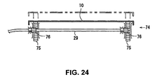
- a plurality of rack members 75 , 75 are fixed to (preferably the bottom face of) the movable floor panel 10 , and pinions 76 , 76 (or worm) meshing with the rack members 75 , 75 are attached to specified (predetermined or predeterminable) portions of the flexible shaft 29 which correspond respectively to the rack members 75 , 75 . Accordingly, the movable floor panel 10 is moved substantially up and down or away and towards the floor panel 7 via the rack and poison mechanism during the rotation of the flexible shaft 29 .
- the pedal position adjusting devices 42 and 42B operative to adjust the operating angles of the pedals 9 and 51 operated by the drivers L , M and S . Accordingly, since the pedal operating angles of the pedals 9 and 51 are adjusted in addition to the adjustment of position of the movable floor panel 10 , the leg of even small size of driver S can reach the pedals enough to provide the proper driving position. This proper driving position can also improve the operation of pedals 9 and 51 and steering wheel 161 and provide the driver with the proper sitting on the seat 4 . Thus, proper views for vehicle side mirrors, providing the narrower view angle, and vehicle meters advantageously are obtained as well.
Abstract
Description
- The present invention relates to a driver driving position adjusting device of a vehicle which is operative to adjust a driving position of a driver on a driver seat and to a corresponding driver position adjusting method.
- In general, the layout of a
seat 100, afloor panel 101 and anaccelerator pedal 102 is designed so as to be suitable for a standard (medium) size of driver M in conventional vehicles as shown in FIG. 37. Theseat 100, which comprises aseat cushion 103, aseat back 104 and aheadrest 105, is supported by a seat slide (not illustrated) as shown in FIG. 38, so that hip points P11, P12 and P13 of drivers L, M and S sitting on theseat cushion 103 are movable substantially horizontally and longitudinally. However, theaccelerator pedal 102 and thefloor panel 101 are both fixed. - Herein, this conventional structure has the following two problems.
- A large size of driver L with a higher eye point can get a sufficiently clear front view with the drivers' eyes illustrated by a broken line eL in FIG. 37 when sitting on the
seat 100. A small size of driver S, however, has a lower eye point and therefore the driver's eyes illustrated by a two-dotted broken line eS in FIG. 37 may be interrupted by ahood 106, thereby providing a difficulty in getting such a clear front view. Particularly, there is a problem that a near view may not be obtained sufficiently. - Meanwhile, the drivers L, M and S operate the
accelerator pedal 102, putting their heels on afloor mat 107 which is placed on thefloor panel 101. Herein, although there may be no particular problem with the large size of driver L and the medium size of driver M, the small size of driver S may have the following problem. Namely, since the leg of the small size of driver S does not reach theaccelerator pedal 102 enough, the above-described operation of theaccelerator pedal 102 with the driver's heal on thefloor mat 107 may require a toe portion to press thepedal 102. Also, thepedal 102 moves forward as thepedal 102 is pressed. Accordingly, it may be difficult for the small size of driver S to operate theaccelerator pedal 102 properly. In order to solve this difficulty, the small size of driver S usually operates theaccelerator pedal 102, after keeping the driver's heel away from thefloor mat 107. - Further, conventionally, the drivers L, M and S adjust their driving positions themselves to obtain the proper operation of the
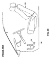
accelerator pedal 102 and a brake pedal and the clear front view. - In order to solve the above-described problems, a conventional driving position adjusting operating device of a vehicle shown in FIG. 39 had been invented (see Japanese Patent Laid-Open Publication No. 7-96784).
- The conventional device shown in FIG. 39 is configured such that a
seat 200 is adjustable in a slant direction between its front-and-upper position and its rear-and-lower position and a brake pedal and/or anaccelerator pedal 201 are movable substantially horizontally and longitudinally in order to provide a proper positional relationship between thepedal 201 and theseat 200 regardless of the body size of driver. - In this conventional device shown in the figure, the leg of the small size of driver may reach the
pedal 201 enough. However, since thepedal 201 is movable only horizontally and longitudinally, the small size of driver still cannot press the center of the pedal properly, putting the heel on a floor mat placed on afloor panel 202 even though thepedal 201 is adjusted in a position (toward the driver) which is illustrated by a solid line in FIG. 39. - The present invention has been devised in view of the above-described problems, and an object of the present invention is to provide a driver driving position adjusting device of a vehicle which can provide a proper driving position and a proper pedal operation regardless of the body size of driver.
- This object is solved by a driver driving position adjusting device of a vehicle according to the present invention of
claim 1 and by a method according toclaim 34. Preferred embodiments of the present invention are subject of the dependent claims. - According to the present invention, there is provided a driver driving position adjusting device of a vehicle, comprising a floor panel position adjusting device operative to adjust at least a position or orientation, preferably a substantially vertical position, of a floor panel on which a leg portion of a driver operating a pedal is or is to be substantially placed, an adjusting device operative to adjust at least one of a seat face position of a driver seat, an operating angle of the pedal to be operated by the leg portion of the driver, and a position of a steering, and a driving position adjusting operating device operative to operate the floor panel position adjusting device and the adjusting device.
- According to the driver driving position adjusting device of a vehicle of the present invention, since at least the vertical position of the floor panel on which the leg portion of the driver operating the pedal is placed is adjusted and this adjustment is done along with the adjustment of at least one of the seat face position of the driver seat, the operating angle of the pedal operated by the leg portion of the driver, and the position of the steering, the proper driving position and the proper pedal operation can be obtained regardless of the body size of driver.
- According to a preferred embodiment, the adjusting device comprises a seat position adjusting device operative to adjust the seat face position of the driver, and the driving position adjusting operating device is operative to operate the floor panel position adjusting device and the seat position adjusting device.
- Accordingly, the seat face can be adjusted in an upper position and the (preferably substantially vertical) position of the floor panel can be adjusted preferably substantially upward for the smaller size of driver, whereas the seat face can be adjusted in a lower position and the (preferably substantially vertical) position of the floor panel can be adjusted preferably substantially downward for the larger size of driver. As a result, regardless of the body size of driver, both the proper driving position and the clear front view can be obtained, and such proper driving position can be obtained even though the longitudinal adjusting distance of the seat is small, and also the proper pedal operation can be obtained by adjusting the vertical position of the floor panel.
- According to another preferred embodiment, the floor panel position adjusting device is operative to adjust the vertical position and/or a panel angle or inclination of the floor panel.
- Accordingly, since the floor panel position adjusting device adjusts preferably not only the vertical position of the floor panel, but also the panel angle of the floor panel, a relative angle between the pedal and the floor panel can be maintained at a substantially constant angle during the vertical movement of the floor panel. Also, even though the size or the heel size of driver's shoes change, such change may be absorbed or taken into account properly by pressing or adjusting an appropriate position of the pedal.
- According to another preferred embodiment, the driving position adjusting operating device is operative to operate the floor panel position adjusting device and the seat position adjusting device such that the devices are operated together with a specified (predetermined or predeterminable) relationship. The specified (predetermined or predeterminable) relationship may be arranged such that the floor panel is moved substantially upward from its lower position when the seat is moved substantially upward and forward from its lower position, whereas the floor panel is moved substantially downward from its upper position when the seat is moved substantially downward and rearward from its upper position.
- Accordingly, since preferably both the floor panel position adjusting device and the seat position adjusting device are operated together by the driving position adjusting operating device, the operation can be simplified and improved.
- According to another preferred embodiment, the seat position adjusting device is operative to adjust a height (or substantially vertical position) and/or an angle of a seat face.
- Accordingly, since both the height and the angle of the seat face are adjusted, the clear front view and the more proper driving position can be obtained regardless of the body size of driver.
- According to another preferred embodiment, the adjusting device further comprises a pedal position adjusting device operative to adjust the operating angle of the pedal operated by the driver.
- Accordingly, since the pedal operating angle is adjusted preferably in addition to the seat face position of the driver seat and the (preferably substantially vertical) position of the floor panel, the proper pedal operation can be provided regardless of the body size of driver.
- According to another preferred embodiment, the driving position adjusting operating device is operative to operate the floor panel position adjusting device, the seat position adjusting device, and the pedal position adjusting device such that the devices are operated together with a specified (predetermined or predeterminable) relationship. The specified (predetermined or predeterminable) relationship may be arranged such that the floor panel is moved upward from its lower position and the pedal is rotated around its rotational center toward the driver when the seat is moved upward and forward from its lower position, whereas the floor panel is moved substantially downward from its upper position and the pedal is rotated substantially around its rotational center away from the driver when the seat is moved substantially downward and rearward from its upper position.
- Accordingly, since the floor panel position adjusting device, the seat position adjusting device and the pedal position adjusting device are operated together by the driving position adjusting operating device, the operation can be simplified and improved.
- According to another preferred embodiment, the floor panel adjusted by the floor panel position adjusting device is moved substantially upward when the seat adjusted by the seat position adjusting device is moved substantially forward and upward.
- Accordingly, both the proper driving position and advantageously the clear front view can be obtained more properly.
- According to another preferred embodiment, the adjusting device comprises the pedal position adjusting device operative to adjust at least the operating angle of the pedal to be operated by the leg portion of the driver, and the driving position adjusting operating device is operative to operate the floor panel position adjusting device and the pedal position adjusting device. Herein, the pedal may be the accelerator pedal and/or the brake pedal and/or the clutch pedal and/or the handbrake or parking position pedal.
- Accordingly, the floor panel can be adjusted respectively: in an upper position (third position) for the small size of driver; in a middle or intermediate position (second position) for the standard size of driver; and in a lower position (first position) for the large size of driver. Also, the pedal operating angle can be preferably adjusted at a substantially constant angle regardless of the body size of driver. As a result, since even the leg of the smaller size of driver reach the pedal enough, the driver can sit on the seat properly and the driving position of the driver can be improved greatly. Thus, the operations of the pedal and the steering wheel are improved, and advantageously proper views for vehicle side mirrors, providing a narrower view angle, and vehicle meters are obtained as well. Additionally, since the pedal operating angle is adjusted at the substantially constant angle regardless of the body size of driver, the optimization of the driver's leg portion during the pedal operation can be attained.
- According to another preferred embodiment, the floor panel position adjusting device is operative to adjust the vertical position and/or a panel angle of the floor panel. It is preferred that the floor panel angle is adjusted respectively: in a front-high and rear-low state when the floor panel is in the lower position; in a substantially horizontal state when the floor panel is in the middle position; and in a front-low and rear-high state when the floor panel is in the upper position.
- Accordingly, since the floor panel position adjusting device adjusts preferably not only the vertical position of the floor panel but also the panel angle of the floor panel, a relative angle between the pedal and the floor panel can be maintained at a substantially constant angle during the vertical movement of the floor pedal. Also, even though the size or the heel size of driver's shoes change, such change may be absorbed or take into account or compensated properly preferably by pressing the appropriate position of the pedal.
- According to another preferred embodiment, the driving position adjusting operating device is operative to operate the floor panel position adjusting device and the pedal position adjusting device such that the devices are adjusted together with a specified (predetermined or predeterminable) relationship. It is preferred that the pedal operating angle is maintained at the substantially constant angle even though the floor panel is (continuously or stepwisely) adjusted from the lower position to the upper position by way of the middle or intermediate position.
- Accordingly, since the floor panel position adjusting device and the pedal position adjusting device are operated together by the driving position adjusting operating device, the operation can be simplified and improved.
- According to another preferred embodiment, the pedal position adjusting device is operative to adjust the operating angle of the pedal and a height of a pedal pressing face.
- Accordingly, since both the pedal operating angle and the pedal pressing face height or position are or can be adjusted, the optimization of the driver's leg portion during the pedal operation can be attained further, and the driver can press the pedal center properly regardless of the body size of driver.
- According to another preferred embodiment, the adjusting device further comprises the seat position adjusting device operative to adjust the seat face position of the driver seat.
- Accordingly, since the seat face position of the driver seat is adjusted by the seat position adjusting device in addition to the adjustments of the pedal operating angle by the pedal position adjusting device and the vertical position of the floor panel (on which the heel of the driver operating the pedal is placed) by the floor panel position adjusting device, the driving position and the state of the driver's leg portion during the pedal operation can be further optimized. Further, the clear front view can be obtained properly, and therefore the front view or line of sight of even the smaller size of driver can be prevented from being interrupted by the vehicle hood.
- According to another preferred embodiment, the driving position adjusting operating device is operative to operate the floor panel position adjusting device, the pedal position adjusting device, and the seat position adjusting device such that the devices are adjusted together with a specified (predetermined or predeterminable) relationship. The specified (predetermined or predeterminable) relationship may be arranged such that the floor panel is moved substantially upward from its lower position when the seat is moved substantially upward and forward from its lower position, whereas the floor panel is moved substantially downward from its upper position when the seat is moved substantially downward and rearward from its upper position.
- Accordingly, since both the pedal position adjusting device and the seat position adjusting device are operated together by the driving position adjusting operating device, the operation can be simplified and improved.
- According to another preferred embodiment, the pedal adjusted by the pedal position adjusting device is moved substantially toward the driver when the floor panel adjusted by the floor panel position adjusting device is moved substantially upward from a lower position thereof.
- Accordingly, since both the floor panel and the pedal are adjusted so as to be suitable for the large, standard and small size of drivers respectively, both the improvement of driving position and the optimization of driver's leg portion during the pedal operation can be attained regardless of the body size of driver.
- According to another preferred embodiment, the adjusting device comprises the seat position adjusting device operative to adjust the seat face position of the driver seat and the pedal position adjusting device operative to adjust the operating angle of the pedal operated by the leg portion of the driver; and the driving position adjusting operating device is operative to adjust the seat, pedal and floor panel such that the driver is moved substantially along a specified arc or path having a center thereof which substantially corresponds to a rotational center of the pedal under a state where a specified (predetermined or predeterminable) driver position is maintained, and is operative to operate the floor panel position adjusting device and the pedal position adjusting device such that the devices are adjusted together with a specified (predetermined or predeterminable) relationship.
- The above-described pedal may be configured so as to be either one, two or all of the accelerator pedal, brake pedal and clutch pedal. It is preferred that the above-described floor panel is configured so as to be a movable floor panel which is separate from an existing part of floor panel which is fixed. Also, it is preferred that the above-described specified (predetermined or predeterminable) relationship is arranged such that the pedal is moved substantially around its rotational center toward the driver when the floor panel is moved substantially upward from its lower position.
- Accordingly, the seat face and the floor panel can be adjusted in their upper positions and the pedal operating angle can be adjusted so as to be suitable for the small size of driver, the seat face and the floor panel can be adjusted in their lower positions and the pedal operating angle can be adjusted so as to be suitable for the large size of driver, and the seat face and the floor panel can be adjusted in their middle positions and the pedal operating angle can be adjusted so as to be suitable for the standard size of driver.
- As a result, regardless of the body size of driver, both the proper driving position and the clear front view, even for the small size of driver, can be obtained, and such proper driving position can be obtained even though the longitudinal adjusting distance of the seat is small, and also the proper pedal operation can be obtained by adjusting the floor panel. Additional, since the pedal operating angle, floor panel position and seat face position are adjusted, optimization of the leg-portion angle and the pedal operating direction of the driver operating the pedal can be attained.
- The difference of body size of the drivers preferably is mainly expressed to the difference of the total length of the thighs and the lower legs (i.e., the difference of length of the legs). Accordingly, the angle between the thigh and lower leg of driver and the operating direction to press the pedal face by the driver who sits on the seat with legs being upward-joint bent depend on the body size of the driver sitting on the seat. Herein, since the seat face position and the pedal operating angle are adjusted respectively by the seat position adjusting device and the pedal position adjusting device, the both (the seat face position and the pedal operating angle) can be adjusted so as to be suitable for the driver's body size. As a result, the optimization of the leg-portion angle and the pedal operating direction of the driver operating the pedal can be attained, and the proper pedal operation can be obtained regardless of the body size of driver.
- Additionally, since the seat, pedal and floor panel are adjusted such that the driver is moved along the specified arc or path having the center thereof which substantially corresponds to the rotational center of the pedal under the state where the specified driver position (comfortable position from the human engineering standpoint or ergonomy) is maintained, the comfortable driving position can be always provided to the driver. Further, since both the pedal position adjusting device and the floor panel position adjusting device are preferably operated together by the driving position adjusting operating device, the operation can be simplified and improved.
- According to another preferred embodiment, the specified (predetermined or predeterminable) relationship is arranged such that the floor panel adjusted by the floor panel position adjusting device is moved substantially upward from the lower position thereof when the pedal adjusted by the pedal position adjusting device is moved substantially around the rotational center of the pedal toward the driver.
- Accordingly, the leg of even the small size of driver can reach the pedal enough to provide the proper driving position. This proper driving position can also improve the operation of pedal and steering wheel and provide the driver with a proper sitting. Thus, proper views for vehicle side mirrors, providing the narrower view angle, and vehicle meters are obtained as well.
- According to another preferred embodiment, the position of the pedal is adjusted by the pedal position adjusting device in relation to the seat position adjustment of the seat position adjusting device.
- Accordingly, since the seat face position and the pedal operating angle are adjusted in relation to each other, further optimization of the leg-portion angle and the pedal operating direction of the driver operating the pedal can be attained. Namely, when the driver is the smaller-size one, the seat face is adjusted in the upper position and also the pedal operating angle is adjusted in relation to this, thereby providing a proper operation state where the pedal is pressed down from above. While, when the driver is the larger-size one, the seat face is adjusted in the lower position and also the pedal operating angle is adjusted in relation to this, thereby providing a proper operation state where the pedal is pressed in a proper direction. Also, further clear front view can be provided even to the smaller size of driver by the adjustment of seat position.
- According to another preferred embodiment, the pedal adjusted by the pedal position adjusting device is moved substantially toward the driver when the seat adjusted by the seat position adjusting device is moved substantially forward and upward from a rear-and-lower position thereof.
- Accordingly, further optimization of the leg-portion angle and the pedal operating direction of the driver operating the pedal can be attained.
- According to another preferred embodiment, the position of the floor panel is adjusted by the floor panel position adjusting device in relation to the seat position adjustment of the seat position adjusting device.
- Accordingly, the seat face position and the floor panel position are adjusted in relation to each other. Since particularly the floor panel position is adjusted, the leg of even the small size of driver can reach the pedal enough to provide the proper pedal operation. Also, since the seat face position is adjusted, sufficiently clear front view can be provided even to the small size of driver.
- According to another preferred embodiment, the floor panel adjusted by the floor panel position adjusting device is moved substantially upward from the lower position when the seat adjusted by the seat position adjusting device is moved substantially forward and upward from the rear and lower position.
- Accordingly, both the proper driving position and the clear front view can be obtained further properly.
- According to another preferred embodiment, the pedal position adjusting device is operative to adjust the operating angle of the pedal and/or the height or substantially vertical position of pedal pressing face.
- Accordingly, the height of pedal pressing face can be adjusted respectively by the pedal position adjusting device: in the lower position for the large size of driver with long legs; in the upper position for the small size of driver with short legs; and in the middle position for the standard size of driver. Thus, since the height of pedal pressing face is adjusted in addition to the adjustment of pedal operating angle, the pedal operation can be further improved, enabling the driver to press the pedal center.
- According to another preferred embodiment, the floor panel position adjusting device is operative to adjust the vertical position or height (or distance to the floor panel) and/or the panel angle or inclination of the (preferably movable) floor panel.
- Accordingly, since the floor panel position adjusting device adjusts not only the vertical position (i.e., height) of the floor panel but also the panel angle or inclination of the floor panel, the relative angle between the pedal and the floor panel can be preferably maintained at the substantially constant angle during the vertical movement of the floor pedal. Also, even though the size or the heel size of driver's shoes change, such change may be absorbed properly by pressing the appropriate position of the pedal (see the pedal center).
- According to another preferred embodiment, the seat position adjusting device is operative to adjust an angle or inclination, a substantially longitudinal position and/or a substantially vertical position of seat face of the driver seat.
- Accordingly, the seat face can be adjusted respectively by the seat position adjusting device: in the front-and-upper position for the small size of driver; in the rear-and-lower position for the large size of driver; and in the middle position for the standard size of driver. Thus, since the longitudinal position and the vertical position of the seat face are adjusted in addition to the seat face angle and the pedal operating angle, further optimization of the leg-portion angle and the pedal operating direction of the driver operating the pedal can be attained, and the clear front view can be provided regardless of the body size of driver, even to the small size of driver.
- According to another preferred embodiment, the driving position adjusting operating device is operative to operate the floor panel position adjusting device, the seat position adjusting device, and the pedal position adjusting device such that the devices are adjusted together with a specified (predetermined or predeterminable) relationship. The specified (predetermined or predeterminable) relationship may be arranged such that the floor panel is moved substantially upward from its lower position and the pedal is rotated substantially around the rotational center toward the driver when the seat is moved substantially upward and forward from its lower position, whereas the floor panel is moved substantially downward from its upper position and the pedal is rotated substantially around the rotational center away from the driver when the seat is moved substantially downward and rearward from its upper position.
- Accordingly, since the floor panel position adjusting device, the seat position adjusting device, and the pedal position adjusting device are operated preferably together by the driving position adjusting operating device, the operation can be simplified and improved.
- According to another preferred embodiment, the adjusting device comprises a steering position adjusting device operative to adjust the position of the steering, and the driving position adjusting operating device is operative to operate the floor panel position adjusting device and the steering position adjusting device.
- It is preferred that the above-described floor panel is configured so as to be the movable floor panel which is separate from the existing part of floor panel which is fixed. Also, the above-described pedal may be configured so as to be at least one of the accelerator pedal, brake pedal and clutch pedal.
- Accordingly, the floor panel can be adjusted respectively: in the upper position for the small size of driver; in the lower position for the large size of driver; and in the middle position for the standard size of driver, so that respective drivers can operate the pedal with their proper leg-portion angles. In addition to this, the steering position can be adjusted according to the body size of driver.
- As a result, the proper driving position can be obtained regardless of the body size of driver. Particularly, the optimization of the leg-portion angle (angles of thighs, lower legs, and feet) and the arm-portion angle (angles of upper arms, lower arms, and hands) can be attained.
- According to another preferred embodiment, the steering position adjusting device is operative to adjust the steering position such that the steering is moved substantially around the rotational center of the pedal.
- Accordingly, the positional relationship between the drivers' arm portion and the steering wheel can be made proper regardless of the body size of driver, maintaining the proper driving position.
- According to another preferred embodiment, the floor panel position adjusting device is operative to adjust the substantially vertical position and/or the panel angle or inclination of the floor panel.
- Accordingly, since the floor panel position adjusting device adjusts not only the vertical position (i.e., height) of the floor panel but also the panel angle of the floor panel, the relative angle between the pedal and the floor panel can be preferably maintained at the substantially constant angle during the vertical movement of the floor pedal. Also, even though the size or the heel size of driver's shoes change, such change may be absorbed properly by pressing the appropriate position of the pedal (see the pedal center).
- According to another preferred embodiment, the driving position adjusting operating device is operative to operate the floor panel position adjusting device and the steering position adjusting device such that the devices are adjusted together with a specified relationship.
- Accordingly, since both the floor panel position adjusting device and the steering position adjusting device are operated together by the driving position adjusting operating device, the operation can be simplified and improved.
- According to another preferred embodiment, the specified relationship is arranged such that the floor panel adjusted by the floor panel position adjusting device is moved substantially upward from the lower position when the steering wheel of steering adjusted by the steering position adjusting device is moved substantially upward.
- Accordingly, further optimization of the leg-portion angle of the driver operating the pedal and the arm-portion angle of the driver operating the steering wheel can be attained.
- According to another preferred embodiment, the steering position adjusting device is operative to adjust the position and the angle of the steering.
- Accordingly, since not only the steering position but also the steering angle are adjusted, the operation of steering wheel can be further improved.
- According to another preferred embodiment, the adjusting device further comprises the pedal position adjusting device operative to adjust the operating angle of the pedal operated by the driver.
- Accordingly, since the pedal operating position is adjusted in addition to the adjustment of floor panel position, the leg of even the small size of driver can reach the pedal enough to provide the proper driving position. This proper driving position can also improve the operation of pedal and steering wheel and provide the driver with the proper sitting. Thus, proper views for vehicle side mirrors, providing the narrower view angle, and vehicle meters are obtained as well.
- According to another preferred embodiment, the adjusting device further comprises the seat position adjusting device operative to adjust the seat face position of the driver seat.
- Accordingly, the seat face position of the driver seat is adjusted by the seat position adjusting device in addition to the adjustments of the floor panel substantially vertical position by the floor panel position adjusting device and the steering position by the steering position adjusting device, even the small size of driver can operate the pedal properly and the clear front view of the driver can be obtained.
- According to another preferred embodiment, when the seat adjusted by the seat position adjusting device is moved substantially forward and upward from the rear-and-lower position, the floor panel adjusted by the floor panel position adjusting device is moved substantially upward from the lower position and the pedal adjusted by the pedal position adjusting device is moved around the rotational center of the pedal toward the driver. The movement of the pedal substantially around the rotational center means the both adjustments of the pedal operating position and the pedal operating angle.
- Accordingly, the seat face and the floor panel can be adjusted in their upper positions and the pedal operating position and angle can be adjusted so as to be suitable for the small size of driver, the seat face and the floor panel can be adjusted in their lower positions and the pedal operating position and angle can be adjusted so as to be suitable for the large size of driver, and the seat face and the floor panel can be adjusted in their middle positions and the pedal operating position and angle can be adjusted so as to be suitable for the standard size of driver.
- As a result, substantially regardless of the body size of driver, both the proper driving position and the clear front view, even for the small size of driver, can be obtained, and such proper driving position can be obtained even though the longitudinal adjusting distance of the seat is small, and also the proper pedal operation can be obtained by adjusting the floor panel. Additionally, since the pedal operating position and angle, floor panel position and seat face position are adjusted, optimization of the leg-portion angle and the pedal operating direction of the driver operating the pedal can be attained. Further, optimization of the arm-portion angle of the driver operating the steering wheel can be attained by the adjustment of steering position.
- The difference of body size of the drivers preferably is mainly expressed to the difference of the total length of the thighs and the lower legs (i.e., the difference of length of the legs). Accordingly, the angle between the thigh and lower leg of driver and the operating direction to press the pedal face by the driver who sits on the seat with legs being upward-joint bent depend on the body size of the driver sitting on the seat. Herein, since the seat face position and the pedal operating position and angle are adjusted respectively by the seat position adjusting device and the pedal position adjusting device, the both (the seat face position and the pedal operating position and angle) can be adjusted so as to be suitable for the driver's body size. As a result, the optimization of the leg-portion angle and the pedal operating direction of the driver operating the pedal can be attained, and the proper pedal operation can be obtained regardless of the body size of driver.
- According to the invention, there is further provided a driver driving position adjusting method for a vehicle, in particular for use with or using a driver driving position adjusting device according to the invention or a preferred embodiment thereof, comprising:
- adjusting at least a position of a floor panel on which a leg portion of a driver operating a pedal is to be placed by means of a floor panel position adjusting device; and
- adjusting at least one of a seat face position of a driver seat, an operating angle of the pedal to be operated by the leg portion of the driver, and a position of a steering by means of an adjusting device; and wherein said floor panel position adjusting device and said adjusting device are both operated concurrently or simultaneously or at the same time or in a combined or corresponding way by a driving position adjusting operating device.
-
- Other features, aspects, and advantages of the present invention will become apparent from the following description of the invention which refers to the accompanying drawings.
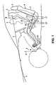
- FIG. 1 is a side view showing a driver driving position adjusting device of a vehicle according to the present invention.
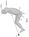
- FIG. 2 is an explanatory diagram of hip point setting.
- FIG. 3 is a side view showing a seat adjustment by a seat position adjusting device.
- FIG. 4 is a side view showing a relational adjustment of a movable floor panel and a pedal.
- FIG. 5 is a side view showing a specific structure of the driver driving position adjusting device of a vehicle.
- FIG. 6 is a side view showing a lower position of the seat.
- FIG. 7 is a side view showing a middle position of the seat.
- FIG. 8 is a side view showing an upper position of the seat.
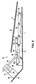
- FIG. 9 is a side view showing a lower position of the movable floor panel.
- FIG. 10 is a side view showing a middle position of the movable floor panel.
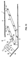
- FIG. 11 is a side view showing an upper position of the movable floor panel.
- FIG. 12 is a perspective view showing a pedal position adjusting device.
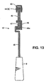
- FIG. 13 is a sectional view of a major part of FIG. 12.
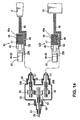
- FIG. 14 is a system diagram showing a position adjusting structure of both pedals using flexible shafts.
- FIG. 15 is an explanatory diagram of a sports mode.
- FIG. 16 is an explanatory diagram of a sedan mode.
- FIG. 17 is an explanatory diagram of a RV mode.
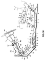
- FIG. 18 is a side view showing a driver driving position adjusting device of a vehicle according to another embodiment.
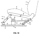
- FIG. 19 is a side view showing a lower position of the seat.
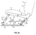
- FIG. 20 is a side view showing a middle position of the seat.
- FIG. 21 is a side view showing an upper position of the seat.
- FIG. 22 is a side view showing a movable floor panel adjusting mechanism according to another embodiment.
- FIG. 23 is a side view showing a movable floor panel adjusting mechanism according to further another embodiment.
- FIG. 24 is a side view showing a movable floor panel adjusting mechanism according to further another embodiment.
- FIG. 25 is a side view showing a movable floor panel adjusting mechanism according to further another embodiment.
- FIG. 26 is a side view showing a middle position of the movable floor panel.
- FIG. 27 is a side view showing an upper position of the movable floor panel.
- FIG. 28 is a side view showing a driver driving position adjusting device of a vehicle according to further another embodiment.
- FIG. 29 is a side view showing a driver driving position adjusting device of a vehicle according to further another embodiment.
- FIG. 30 is a side view showing a driver driving position adjusting device of a vehicle according to further another embodiment.
- FIG. 31 is a side view showing a steering position adjusting device.
- FIG. 32 is an explanatory diagram of a steering position for a large size of driver.
- FIG. 33 is an explanatory diagram of a steering position for a small size of driver.
- FIG. 34 is a sectional view taken along line A-A of FIG. 32.
- FIG. 35 is a side view showing a steering position adjusting device according to another embodiment.
- FIG. 36 is a side view showing a driver driving position adjusting device of a vehicle according to further another embodiment.
- FIG. 37 is a side view showing a problem of a conventional vehicle.
- FIG. 38 is a side view showing a conventional seat adjustment of a vehicle.
- FIG. 39 is a side view showing a conventional driver driving position adjusting device of a vehicle.
-
- Preferred embodiments of the present invention, in particular of a preferred driver driving position adjusting device and/or driver driving position adjusting method, will be described referring to the accompanying drawings. It should be understood that even though embodiments are separately described, single features thereof may be combined to additional embodiments.
- The figures show a preferred driver driving position adjusting device of a vehicle. First, a general introduction of its basic structure and of the respective adjusting method will be described referring to FIGS. 1 through 4.
- In FIGS. 1 through 4, a reference character L denotes a large size of driver, a reference character M denotes a standard (medium) size of driver, and a reference character S denotes a small size of driver. The drivers L, M and S sit on a seat (driver seat) 4 including a
seat cushion 1, a seat back 2 and aheadrest 3. - A
reference numeral 5 denotes a hood, areference numeral 6 denotes a dash lower panel (dash panel),and areference numeral 7 denotes a floor panel (so-called base floor). At the side of the dashlower panel 6 is provided anaccelerator pedal 9 as a pedal which is movable or rotatable or pivotable substantially around arotational center 8. Although thefloor panel 7 is fixed, there is provided amovable floor panel 10 at a portion, on which a leg portion (see a heel) of the drivers L, M and S operating theaccelerator pedal 9 and abrake pedal 51, which is described below (see FIG. 14), is placed or placeable. Accordingly, a dual floor structure consisting of the floor panel (fixed floor) 7 and themovable floor panel 10 being movable with respect thereto is constituted. - Generally, it is said from the human engineering standpoint that human being (driver) feels comfortable in a position where the thigh and lower leg are open (or at a relatively greater angle) when the sitting position is low, and feels comfortable in a position where the thigh and lower leg are closed (or at a relatively smaller angle) when the sitting position is high. Herein, in view of the concept that the driver always feel comfortable with the hip points which are decided by rotating the driver positions approximately around the
rotational center 8 of theaccelerator pedal 9, maintaining the above-described comfortable positions, the hip points of driver will be set as described below. - For the large size of driver L, by lowering the hip point P1' of the driver L in a RV mode (recreational vehicle mode) shown in FIG. 2 to the hip point P1 in a sedan mode along the arc having its center corresponding to the
rotational center 8 of theaccelerator pedal 9, maintaining the comfortable position with an opening angle (approximately 128 degrees) between the thigh and lower leg which is slightly narrower than a conventional angle (approximately 135 degrees), the hip point P1 is set in a lower-and-forward position with respect to the conventional hip point P11. - For the small size of driver S, by raising the hip point to the hip point P3 along the arc having its center corresponding to the
rotational center 8 of theaccelerator pedal 9, maintaining the comfortable position with the opening angle (approximately 130 degrees) between the thigh and lower leg which is slightly greater than a conventional angle (approximately 114 degrees), the hip point P3 (see FIG. 1) is set in an upper-and-rearward position with respect to the conventional hip point P13. Accordingly, the eyes or line of sight e of respective drivers L, M and S are configured so as to be on the substantially identical line as shown in FIG. 1. - In FIGS. 3 and 4, respective positions of the
seat 4, theaccelerator pedal 9 and themovable floor panel 10 are illustrated respectively: by the broken line with reference characters a, h, d for the large size of driver L; by the solid line with reference characters b, i, f for the standard size of driver M; and by the two-dotted broken line with reference characters c, j, g for the small size of driver S. - Namely, the
seat 4 is configured such that the position of seat face 12 of theseat cushion 1 is moved upward and forward from the lower position along aline 11 passing the hip point P1 for the driver L and the hip point P3 for the driver S shown in FIG. 3. Also, both height and/or angle or inclination of theseat face 12 are adjustable. - Herein, the seat face angle of the
seat cushion 1 is adjusted so as to change from the front-high and rear-low position to the horizontal position when theseat 4 is moved substantially forward and upward as apparent from FIG. 3. Also, the operating angle of theaccelerator pedal 9 is adjusted in such a manner that thepedal 9 is rotated or moved substantially around itsrotation center 8 toward the driver, from the position h (see the broken line) for the large size of driver L to the position j (see the two-dotted broken line) for the small size of driver S, as shown in FIG. 4. - Further, the
movable floor panel 10 is moved upward (or substantially away from the floor panel 7) when theaccelerator pedal 9 is moved toward the driver as shown FIG. 4. Herein, the floor panel angle of themovable floor panel 10 is adjusted so as to change from the front-high and rear-low position (see position d) to the front-low and rear-high position (see position g) by way of the horizontal position (see position f) when themovable floor panel 10 is moved upward (or substantially away from the floor panel 7) from the lower position. As a result, the angles and ϕ between theaccelerator pedal 9 and themovable floor panel 10 have the substantially same respective values regardless of the positions d, f, g of themovable floor panel 10. - Since the hip point P1 for the large size of driver L is set in the lower-and-forward position with respect to the conventional hip position P11 as shown in FIG. 1, the
seat 4 can be located forward by a distance L1. Accordingly, it may be possible to enlarge the rear-seat space and improve the package efficiency without changing the vehicle space or the wheel base length. Also, since this forward location of theseat 4 allows the driver to sit forward with respect to a center pillar, the driver can be protected properly against the center pillar which may be deformed inward during a vehicle side collision, thereby improving the safety. - Also, since the hip point P3 for the small size of driver S is set in the upper-and-rearward position with respect to the conventional hip position P13 as shown in FIG. 1, the distance between the hip points P3 and P1 can be shortened. Accordingly, the adjusting amount of the
seat 4 substantially in the longitudinal direction can be shortened by a total of the distance L1 and the distance L2. Also, since the hip point P3 for the small size of driver S is set in the rearward position with respect to the conventional one, proper views for vehicle side mirrors, providing the narrower view angle, and vehicle meters can be obtained. - FIG. 5 shows an embodiment which materializes the basic structure shown in FIGS. 1 through 4. In FIG. 5, a first (preferably substantially lower)
rail 13 and a second (preferably substantially upper)rail 14 are attached to the floor panel 7 (fixed base floor) located at the seat 4 (driver seat), and there is provided a seat slide or movingmechanism 15 to slide or move theseat 4 substantially longitudinally according to the driver's needs. Herein, theupper rail 14 is usually fixed with respect to thelower rail 13. Between theupper rail 14 and aseat frame 16 to which theseat cushion 1 is to be fixed is provided a seatposition adjusting device 17 operative to adjust longitudinal and/or vertical positions of seat face and/or an angle of seat face of theseat 4 together. - The seat
position adjusting device 17 preferably is configured as shown in FIGS. 6, 7 and 8. Namely,support brackets upper rail 14, thefront support bracket 18 and the front end of theseat frame 16 are movably coupled by a link orarm 20 preferably via pins, therear support bracket 19 and the rear end of theseat frame 16 are movably coupled by another link orarm 21 preferably via pins, and the length of thefront link 20 is configured so as to be longer than that of therear link 21. - Also, a
gearbox 22 is attached to theupper rail 14, agear 24 is driven by an operation of alever 23 which constitutes a driving position adjusting operating device, thegear 24 rotates a pinion (or a worm) via agear 25 in the gearbox, and arack member 27 is configured so as to move back and forth via thepinion 26. Further, apin 28 at the rear end of therack member 27 is at least partly inserted in a long oroblong hole 21 a of therear link 21, and thelink 21 is configured so as to get up or down or recline forward or backward according to the back-and-forth movement of therack member 27. - Accordingly, the
seat 4 is adjusted in the respective positions a, b, c shown in FIGS. 6, 7 and 8 via the seatposition adjusting device 17 preferably with a double-link structure according to the operation of the (preferably manually-operated or operable)lever 23. Herein, the position a shown in FIG. 6 corresponds to a sear or sitting state of the large size of driver L, the position b shown in FIG. 7 corresponds to a seat or sitting state of the standard size of driver M, the position c shown in FIG. 8 corresponds to a seat or sitting state of the small size of driver S, and the seat face angle and/or height are adjustable preferably together as described above because the front andrear links - Further, to the above-described
pinion 26 is attached a flexible shaft 29 (so-called bending shaft), shown in FIG. 5, or a power transmitting cable as a linkage device. Also, as shown in FIG. 5, there is provided a movable floorpanel adjusting mechanism 30 as a preferred floor panel position adjusting device which adjusts or can adjust preferably together the vertical position and/or the floor panel angle of themovable floor panel 10 on which the leg portion (see heel) of the driver operating theaccelerator pedal 9 and thebrake pedal 51 described below is positioned (see FIG. 14). The movable floorpanel adjusting mechanism 30 preferably is configured as shown in FIGS. 9, 10 and 11. - Namely, a
support bracket 31 is attached to the upper face of the fixedfloor panel 7,brackets movable floor panel 10, the front portion of thesupport bracket 31 and thefront bracket 32 are movably coupled by alink 34 preferably via pins, the rear portion of thesupport bracket 31 and therear bracket 33 are movably coupled by anotherlink 35 preferably via pins, and the length of therear link 35 is configured so as to be longer than that of thefront link 34. - Also, a
gearbox 37 is attached via abracket 36 to a lower-end slant portion 6a of the dashlower panel 6, utilizing an open space, arack member 39 is driven by apinion 38 or a worm which is supported in thegearbox 37, apin 40 at the rear end of therack member 39 is inserted in a long oroblong hole 34a of thefront link 34, and thelink 34 is configured so as to get up or down or recline forward or backward according to the back-and-forth movement of the above-describedrack member 39. - Herein, the above-described
pinion 38 is configured so as to be rotated or pivoted by the flexible shaft 29 (or the power transmission cable) as shown in FIG. 5 as well. Namely, themovable floor panel 10 is adjusted via the movable floorpanel adjusting mechanism 30 preferably with a double-link structure in the respective positions d, f, g shown in FIGS. 9, 10 and 11 according to the rotation of theflexible shaft 29. The vertical position and the floor panel angle of themovable floor panel 10 correspond respectively to the states shown by broken, solid and two-dotted broken lines in FIG. 4. The position d shown in FIG. 9 corresponds to a leg-portion placing state of the large size of driver L, the position f shown in FIG. 10 corresponds to a leg-portion placing state of the standard size of driver M, and the position g shown in FIG. 11 corresponds to a leg-portion placing state of the small size of driver S. The above-describedmovable floor panel 10 and/or thefloor panel 7 is/are at least partly covered by afloor mat 41 as shown in FIG. 5. Herein, themovable floor panel 10 is configured such that the vertical movement and/or angular change thereof are adjusted preferably together because the length of the front andrear links panel adjusting mechanism 30 with the double-link structure are preferably different from each other. - Further, as shown in FIG. 5, there is provided a pedal
position adjusting device 42 which adjusts preferably together the operating angle and/or the height of pressing face of theaccelerator pedal 9 operated or to be operated by the drivers L, M and S. The pedalposition adjusting device 42 preferably is configured as shown in FIGS. 12 and 13. - Namely, a pedal bracket upper 45 is pivoted at a
bracket 43 to be attached to the dashlower panel 6 via asupport shaft 44 substantially constituting or defining therotational center 8 of thepedal 9, and a guide member 46 (preferably with an arc-shape orbent guide groove 46a) substantially having its center at therotational center 8 is attached integrally or unitarily at a lower potion of the pedal bracket upper 45. - At the above-described
guide groove 46a is provided aslider 47 which is movable along its arc or bent shape. A pedal portion (pressing face portion) of theaccelerator pedal 9 is attached to theslider 47 via a pedal bracket lower 48. - Also, a
rack portion 49 is formed integrally at theslider 47, and a worm (or rack and pinio) 50 is disposed so as to engage with therack portion 49 all the time. The worm is driven and rotated by the flexible shaft 29 (specifically, aflexible shaft 29A at the accelerator-pedal side, shown in FIG. 14). - And, when the
flexible shaft 29 is rotated, theaccelerator pedal 9 is moved or displaced substantially back and forth substantially around the rotational center 8 (see support shaft 44) via the pedalposition adjusting device 42 as shown in FIGS. 4 and 5. The lower position h of theaccelerator pedal 9 shown in FIGS. 4 and 5 substantially corresponds to the large size of driver L, the middle position i substantially corresponds to the standard (medium) size of driver M, and the upper position j substantially corresponds to the small size of driver S. Theaccelerator pedal 9 is adjusted respectively in the positions h, i, j via theworm 50,rack portion 49 andslider 47 according to the rotation of theflexible shaft 29, and the operating angle and/or height of the pressing face of thepedal 9 are adjusted preferably together by the pedalposition adjusting device 42. - The
brake pedal 51 preferably is configured, as shown in a system diagram FIG. 14, so as to be moved or displaced substantially back and forth substantially around therotational center 8 via a similar pedalposition adjusting device 42B to the above-describeddevice 42 for theaccelerator pedal 9. The same or similar parts of thedevices flexible shaft 29 is split into the accelerator-pedal-sideflexible shaft 29A and a brake-pedal-sideflexible shaft 29B, which rotate concurrently or in the same direction or by the substantially same amount, via agearbox 52. - The
gearbox 52 supports rotatably a (preferably single)input gear 53 and two output gears 54 and 55 therein, and theinput gear 53 engages with the output gears 54 and 55. A front end of theflexible shaft 29 is fixed to an input side of theinput gear 53 via an inner shaft cramp orclamp 56. Respective base ends of theflexible shafts accelerator pedal 9 and thebrake pedal 51 are fixed respectively to output sides of the output gears 54 and 55 via inner shaft cramps or clamps 56A and 56B. Theflexible shafts accelerator pedal 9 and thebrake pedal 51 are configured so as to rotate in the same direction via thegears flexible shaft 29. - Herein, in the figure, a
reference numeral 57 denotes a cylindrical outer shaft, and areference numeral 58 denotes an attaching member to attach theouter shaft 57 to thegearbox 52. Further, in the preferred embodiment of the present embodiment, there is provided a driving position adjusting operating device operative to operate the above-described seatposition adjusting device 17, movable floorpanel adjusting mechanism 30 and/or pedalposition adjusting devices flexible shafts - And, the driving position adjusting operating device comprising the
lever 23 and theflexible shafts position adjusting device 17, movable floorpanel adjusting mechanism 30 and/or pedalposition adjusting devices - Namely, when the
seat cushion 1 of theseat 4 is moved from the rear-and-lower position a to the front-and-upper position c by way of the middle position b by the seatposition adjusting device 17 to locate respective eyes or lines of sight e of the drivers L, M and S on the substantially identical line as shown in FIG. 1, themovable floor panel 10 and the accelerator andbrake pedals movable floor panel 10 is moved from the first (lower) position d to the third (upper) position g by way of or via the second (middle or intermediate) position f by the movable floorpanel adjusting mechanism 30 and the bothpedals position adjusting devices - Also, the above-described seat
position adjusting device 17 preferably is configured so as to adjust not only the longitudinal and vertical positions of seat face of theseat cushion 1, but also the angle of seat face of theseat cushion 1 preferably together. Accordingly, the seat-face angle of theseat cushion 1 is adjusted from the front-high and rear-low position to the substantially horizontal position as shown in FIG. 3 according to the movement of theseat cushion 1 from the position a shown in FIG. 6 to the position c shown in FIG. 8 by way of the position b shown in FIG. 7. - Further, the movable floor
panel adjusting device 30 preferably is configured so as to adjust not only the vertical position of themovable floor panel 10, but also its angle or inclination with respect to thefloor panel 7 together. Accordingly, themovable floor panel 10 is adjusted from the front-high and rear-low position (see FIG. 9) to the front-low and rear-high position (see FIG. 11) by way of the substantially horizontal position (see FIG. 10) according to the movement of themovable floor panel 10 from the first (lower) position d (see FIG. 9) to the third (upper) position g (see FIG. 11) by way of the second (middle) position f (see FIG. 10). Herein, the angles and ϕ (see FIG. 4) between themovable floor panel 10 in respective positions d, f, g and the pedal in the corresponding positions h, i, j preferably are configured so as to have the substantially same values regardless of their positions. - Additionally, the above-described pedal
position adjusting devices pedals pedals movable floor panel 10 in such a manner that it is located: in the lower position h when themovable floor panel 10 is in the first (lower) position d (see FIG. 9); in the second (middle) position i when themovable floor panel 10 is in the middle position f (see FIG. 10); and in the third (upper) position j when themovable floor panel 10 is in the lower position g (see FIG. 11). - Namely, relationships between the drives L, M and S and the respective positions of the
seat cushion 1,movable floor panel 10 andpedals - As described above, according to the embodiment shown in FIGS 1 through 14, there is provided the driver driving position adjusting device of a vehicle preferably comprising the seat
position adjusting device 17 operative to adjust the seat face position (vertical and/or longitudinal positions) of theseat 4 on which the drivers L, M and S sit, the pedalposition adjusting devices pedals panel adjusting mechanism 30 operative to adjust the position of themovable floor panel 10 on which the leg portions of the drivers L, M and S operating thepedals lever 23,flexible shafts seat 4,pedals movable floor panel 10 such that the driver is moved along the arc substantially having its center which corresponds to therotational center 8 of thepedals position adjusting devices panel adjusting mechanism 30 with the specified (predetermined or predeterminable) relationship. - Accordingly, the seat
position adjusting device 17 adjusts the seat-face position of theseat 4 on which the drivers L, M and S, the pedalposition adjusting devices pedals panel adjusting mechanism 30 adjusts the position of themovable floor panel 10 on which the leg portions (specifically, see the heels) of the driver operating thepedals - Thus, the seat face of the
seat 4 and themovable floor panel 10 can be adjusted in their upper positions and the pedal operating angle of thepedals seat 4 and themovable floor panel 10 can be adjusted in their lower positions and the pedal operating angle of thepedals seat 4 and themovable floor panel 10 can be adjusted in their middle positions and the pedal operating angle of thepedals - As a result, regardless of the body size of drivers L, M and S, both the proper driving position and the clear front view, even for the small size of driver S, can be obtained, and such proper driving position can be obtained even though the longitudinal adjusting distance of the
seat 4 is small, and also the proper pedal operation can be obtained by adjusting themovable floor panel 10. Additionally, since the pedal operating angle of thepedals movable floor panel 10 and the seat face position of theseat 4 are adjusted, the optimization of the leg-portion angle and the pedal operating direction of the drivers L, M and S operating thepedals - Namely, the difference of body size of the drivers is mainly expressed to the difference of the total length of the thighs and the lower legs (i.e., the difference of length of the legs). Accordingly, the angle between the thigh and lower leg of driver and the operating direction to press the pedal face by the driver who sits on the
seat 4 with legs being upward-joint bent depend on the body size of the driver sitting on the seat. Herein, since the seat face position of theseat 4 and the pedal operating angle of thepedals position adjusting device 17 and the pedalposition adjusting devices pedals 9 and 51) can be adjusted so as to be suitable for the driver's body size. As a result, the optimization of the leg-portion angle and the pedal operating direction of the driver operating thepedals - Additionally, since the
seat 4, thepedals movable floor panel 10 are adjusted such that the driver is moved along the specified (predetermined or predeterminable) arc or path substantially having the center thereof which corresponds to therotational center 8 of thepedals - Further, since both the pedal
position adjusting devices panel adjusting mechanism 30 are operated together by the driving position adjusting operating device (see preferably thelever 23 and theflexible shafts - Also, the above-described specified (predetermined or predeterminable) relationship preferably is arranged such that the
movable floor panel 10 adjusted by the movable floorpanel adjusting mechanism 30 is moved upward from the lower position thereof when thepedals position adjusting devices rotational center 8 toward the driver. Accordingly, the leg of even small size of driver S can reach thepedals pedals seat 4. Thus, proper views for vehicle side mirrors, providing the narrower view angle, and vehicle meters are advantageously obtained as well. - Further, the positions of the
pedals position adjusting devices position adjusting device 17. Accordingly, since the seat face position of theseat 4 and the pedal operating angle of thepedals pedals seat 4 is adjusted in the upper position and also the pedal operating angles of thepedals pedals seat 4 is adjusted in the lower position and also the pedal operating angles of thepedals pedals - Additionally, the
pedals position adjusting devices seat 4 adjusted by the seatposition adjusting device 17 is moved substantially forward and/or upward from its rear-and-lower position. Accordingly, further optimization of the leg-portion angle and the pedal operating direction of the drivers L, M and S operating thepedals - Further, the position of the
movable floor panel 10 is adjusted by the movable floorpanel adjusting mechanism 30 in relation to the seat position adjustment by the seatposition adjusting device 17. Accordingly, the seat face position of theseat 4 and the floor panel position of themovable floor panel 10 are adjusted in relation to each other. Since particularly the floor panel position of themovable floor panel 10 is adjusted, the leg of even the small size of driver S can reach thepedals seat 4 is adjusted, sufficiently clear front view can be provided even to the small size of driver S. - Herein, the
movable floor panel 10 adjusted by the movable floorpanel adjusting mechanism 30 is moved substantially upward from the lower position when theseat 4 adjusted by the seatposition adjusting device 17 is moved forward and upward from the rear and lower position. Accordingly, both the proper driving position and the clear front view can be obtained further properly. - Further, the pedal
position adjusting devices pedals pedals position adjusting devices pedal pedals pedals - Additionally, the movable floor
panel adjusting mechanism 30 is operative to adjust the vertical position and/or the panel angle or inclination of themovable floor panel 10. Accordingly, since the movable floorpanel adjusting mechanism 30 preferably adjusts not only the vertical position (i.e., height) of themovable floor panel 10 but also the panel angle or inclination of themovable floor panel 10, the relative angles between thepedals movable floor panel 10 can be maintained at the substantially constant angles during the vertical movement of themovable floor panel 10. Also, even though the size or the heel size of driver's shoes change, such change may be absorbed properly by pressing the appropriate position of thepedals 9 and 51 (see the pedal center). - Also, the seat
position adjusting device 17 is operative to adjust the angle, the longitudinal position and/or the vertical position of seat face of thedriver seat 4. Accordingly, the seat face of theseat 4 can be adjusted respectively by the seat position adjusting device 17: in the front-and-upper position for the small size of driver S; in the rear-and-lower position for the large size of driver L; and in the middle position for the standard size of driver M. - Thus, since the longitudinal position and the vertical position of the seat face of the
seat 4 are adjusted in addition to the seat face angle of theseat 4 and the pedal operating angles of thepedals pedals - Further, the driving position adjusting operating device (see the
lever 23 and theflexible shafts panel adjusting mechanism 30, the seatposition adjusting device 17, and the pedalposition adjusting devices - The specified (predetermined or predeterminable) relationship preferably is arranged such that the
movable floor panel 10 is moved upward from its lower position and thepedals rotational center 8 toward the driver when theseat 4 is moved upward and forward from its lower position, whereas themovable floor panel 10 is moved downward from its upper position and thepedals rotational center 8 away from the driver when theseat 4 is moved downward and rearward from its upper position. - Accordingly, since the movable floor
panel adjusting mechanism 30, the seatposition adjusting device 17, and the pedalposition adjusting devices lever 23 and theflexible shafts - FIGS. 15, 16 and 17 show respectively the sports mode, the sedan mode and the RV mode (recreational vehicle mode), which are selected by the same body size of driver X by use of the above-described driver driving position adjusting device. The sports mode shown in FIG. 15 is provided by setting the
seat cushion 1 and theaccelerator pedal 9 in the respective positions a and h (herein, illustrating the position of themovable floor panel 10 is omitted), the sedan mode shown in FIG. 16 is provided by setting them in the respective positions b and i, and the RV mode shown in FIG. 17 is provided by setting them in the respective positions c and j. Particularly, the state shown in FIG. 17 can provide a sufficiently wide space of foot space for a rear passenger Y and an enlarged rear-seat space, and further improve the package efficiency. - FIGS. 18 through 21 show another preferred embodiment of the driver driving position adjusting device of a vehicle. In the previous embodiment, the pinion 26 (or worm) in the
gearbox 22 at the seatposition adjusting device 17 is manually operated by thelever 23 fixed to thegear 24. In the present embodiment shown in FIGS. 18 through 21, however, the pinion 26 (or worm) is driven by a motor (reversible motor), and there is provided aswitch box 61 comprising a first switch (switch for rotating the motor in a certain direction) 62 and a second switch (switch for rotating the motor in a reverse direction) 63. - In other words, the first and
second switches flexible shafts position adjusting device 17, the movable floorpanel adjusting mechanism 30 and the pedalposition adjusting devices - This electrically-operated driving position adjusting operating device can also perform substantially the same functions and effects as those of the device in the previous embodiment. Accordingly, the same parts shown in FIGS. 18 through 21 as those shown in FIGS. 5 through 8 are denoted by the same reference characters and detailed description on them are omitted here.
- FIGS. 22 through 27 show another preferred embodiment of the movable floor panel adjusting mechanism.
- In a movable floor
panel adjusting mechanism 64 shown in FIG. 22, a plurality ofguide cylinders 65 havingscrew holes 65a are fixed to (preferably the bottom face of) themovable floor panel 10, and drivenbevel gears 67 are integrally attached to lower portions of screws (screw shafts) 66 to mesh with therespective screw holes 65a. Meanwhile, drivingbevel gears 68 are attached at specified (predetermined or predeterminable) portions of theflexible shaft 29 so as to mesh with the driven bevel gears 67. Accordingly, themovable floor panel 10 is moved up and down (or substantially away and towards the floor panel 7) by therespective parts flexible shaft 29. Preferably, the movable floorpanel adjusting mechanism 64 moves themovable floor panel 10 in a substantially parallel posture or without substantially changing its inclination. However, due to different screw pitches of the front andrear guide cylinders 65 and screws 66 a relatively different stroke can be achieved for s specifies amount og rotation of theflexible shaft 29 so that different inclinations of themovable floor panel 10 can be achieved concurrently with its substantially vertical movement (i.e. towards and away from the floor panel 7). - The movable floor
panel adjusting mechanism 64 shown in FIG. 22 can move up and down themovable floor panel 10, on which the heel of the driver operating thepedals - In a movable floor
panel adjusting mechanism 69 shown in FIG. 23,support brackets 70 are attached to (preferably the bottom face of) themovable floor panel 10, and asupport member 71 is provided at a side of the fixed floor panel 7 (see the previous drawing). And, both ends of twolinks oblong holes support brackets 70 and thesupport member 71 preferably via pins, and theflexible shaft 29 is provided at the intersection portion of the twolinks links movable floor panel 10 is moved substantially up and down or relatively to thefloor panel 7 via thelinks flexible shaft 29. - The movable floor
panel adjusting mechanism 69 shown in FIG. 23 can move up and down themovable floor panel 10, on which the heel of the drivers L, M and S operating thepedals - In a movable floor
panel adjusting mechanism 74 shown in FIG. 24, a plurality ofrack members movable floor panel 10, and pinions 76, 76 (or worm) meshing with therack members flexible shaft 29 which correspond respectively to therack members movable floor panel 10 is moved substantially up and down or away and towards thefloor panel 7 via the rack and poison mechanism during the rotation of theflexible shaft 29. - The movable floor
panel adjusting mechanism 74 shown in FIG. 24 can move substantially up and down themovable floor panel 10, on which the heel of the drivers L, M and S operating thepedals - In a movable floor
panel adjusting mechanism 77 shown in FIGS. 25 through 27,support brackets movable floor panel 10, and asupport member 80 is to be fixed at the side of the fixed floor panel 7 (see the previous drawing). The front end of thesupport member 80 and a long oroblong hole 79a at therear bracket 79 are coupled by alink 81 via pins, and a long oroblong hole 80a of thesupport member 80 and thefront bracket 78 are coupled by anotherlink 82 preferably via pins. - And, the
flexible shaft 29 is provided at an intersection portion of the above-described twolinks links links - Also, the
flexible shaft 29 provided at the intersection portion is configured so as to transfer the rotational force preferably only to thelink 81 of the twolinks movable floor panel 10 is moved substantially vertically and slant or inclined to the positions d, f, g shown in FIGS. 25, 26 and 27 via thelinks flexible shaft 29. - In the movable floor
panel adjusting mechanism 77 shown in FIGS. 25 through 27, the vertical position and/or operating angle of themovable floor panel 10 on which the heel of the drivers L, M and S operating thepedals movable floor panel 10 slants in the front-high and rear-low state in its low position d shown in FIG. 25, it lies almost horizontally in its intermediate or middle position f shown in FIG. 26, and it slants or is inclined reversely in the front-low and rear-high state in its high position g shown in FIG. 27. Herein, an arrow F in FIGS. 25 through 27 shows the vehicle's forward direction. - FIG. 28 shows further another preferred driver driving position adjusting device of a vehicle. In the previous embodiments shown in FIGS. 5 and 18, the seat
position adjusting device 17, movable floorpanel adjusting mechanism 30 and pedalposition adjusting devices position adjusting device 17 and the movable floorpanel adjusting mechanism 30 are adjusted together. - Namely, the embodiment shown in FIG. 28 shows the driver driving position adjusting device of a vehicle which preferably comprises the seat
position adjusting device 17 operative to adjust or change the seat face position of theseat 4, the movable floorpanel adjusting mechanism 30 operative to adjust or change at least the substantially vertical position of themovable floor panel 10 on which the leg portion of the driver operating thepedal 9 is placed, and/or the driving position adjusting operating device (see thelever 23 and the flexible shaft 29) operative to operate the seatposition adjusting device 17 and the movable floorpanel adjusting mechanism 30. - Accordingly, the seat
position adjusting device 17 preferably adjusts the seat face position of theseat 4, the movable floorpanel adjusting mechanism 30 adjusts at least the substantially vertical position of themovable floor panel 10 on which the leg portion (see heel) of the driver operating thepedal 9 is placed, and/or the driving position adjusting operating device (see thelever 23 and the flexible shaft 29) operative to operate the seatposition adjusting device 17 and the movable floorpanel adjusting mechanism 30. - Accordingly, the seat face of the
seat 4 can be adjusted in the upper position and/or the vertical position of themovable floor panel 10 can be adjusted upward for the smaller size of driver S, whereas the seat face of theseat 4 can be adjusted in the lower position and/or the vertical position of themovable floor panel 10 can be adjusted downward for the larger size of driver L. As a result, regardless of the body size of driver, both the proper driving position and the clear front view can be obtained, and such proper driving position can be obtained even though the longitudinal adjusting distance of theseat 4 is small, and also the proper pedal operation can be obtained by adjusting the vertical position of themovable floor panel 10. - Since other structures, functions and effects of the embodiment shown in FIG. 28 are substantially the same as those of the previous embodiment, the similar or same parts are denoted by the same reference characters and detailed descriptions on those are omitted here.
- FIG. 29 shows further another preferred driver driving position adjusting device of a vehicle. In the previous embodiments shown in FIGS. 5 and 18, the seat
position adjusting device 17, movable floorpanel adjusting mechanism 30 and pedalposition adjusting devices panel adjusting mechanism 30 and the pedalposition adjusting devices - Namely, the embodiment shown in FIG. 29 shows the driver driving position adjusting device of a vehicle which comprises the pedal
position adjusting devices 42 and 43B operative to adjust at least pedal operating angles of thepedals panel adjusting mechanism 30 operative to adjust at least the substantially vertical position of themovable floor panel 10 on which the leg portions (see heel) of the drivers L, M and S operating thepedals lever 23 and theflexible shaft position adjusting devices panel adjusting mechanism 30. - Accordingly, the pedal
position adjusting devices 42 and 43B adjusts or can adjust at least pedal operating angles of thepedals panel adjusting mechanism 30 adjusts at least the vertical position of themovable floor panel 10 on which the leg portions of the drivers L, M and S operating thepedals lever 23 and theflexible shaft position adjusting devices panel adjusting mechanism 30. - Accordingly, the
movable floor panel 10 can be adjusted respectively: in the upper position g for the small size of driver S; in the middle position f for the medium size of driver M; and in the lower position d for the larger size of driver L. Also, the pedal operating angles of thepedals - As a result, since the foot of even small size of driver S reaches the
pedals seat 4 properly, the driver driving position can be further improved, thereby improving the operations of thepedals - Also, since the pedal operating angle preferably is maintained at substantially the same angle regardless of the body size of drivers L, M and S, the optimization of the leg portion of driver during the pedal operation can be attained.
- Likewise, since other structures, functions and effects of the embodiment shown in FIG. 29 are similar or substantially the same as those of the previous embodiment, the similar or same parts are denoted by the same reference characters and detailed descriptions on those are omitted here.
- FIGS. 30 through 36 show further another preferred embodiment of a driver driving operating adjusting device which is operative to also adjust the steering position.
- As shown in FIG. 30, there is provided a steering
position adjusting device 162 which adjusts together the positions and angles of asteering shaft 160 and/or asteering wheel 161. - The steering
position adjusting device 162 is configured as shown in FIGS. 31 through 34. Behind a dash lower 164 interposed between acowl panel 163 and the dashlower panel 6 is provided asteering support member 167 as a vehicle body rigidity member laterally via steeringsupport brackets - Meanwhile, the steering
shaft 160 comprises afirst shaft 168 and asecond shaft 169, which are interconnected via auniversal joint 170 as a steering joint. Thefirst shaft 168 is configured so as to be adjusted substantially around the above-describedrotational center 8 by locating a lower portion of thefirst shaft 168 substantially at therotational center 8 in a vehicle width direction. - At a first end or lower portion of the
second shaft 169 is provided a steering gear, and asteering wheel 161 is provided at a first end or upper portion of thefirst shaft 168. A main part of thefirst shaft 168 is at least partly covered by asteering column 171 preferably as a shaft tube. - A pair of (upper and lower)
steering support members steering support member 167 which crosses thesteering column 171 above thesteering column 171 as shown in FIGS. 32 and 33. Namely, alower flange 172a of the uppersteering support member 172 and anupper flange 173a of the lowersteering support member 173 are connected by a bolt-nut 174, thereby fixing thesteering support members steering support member 167. - The lower
steering support member 173 preferably is substantially L-shaped, and returnpieces support members pieces grooves slider 175 to move relatively thereto (preferably go substantially up or down). - The
slider 175 holds thesteering column 171 preferably substantially from both sides by a pair ofcramp portions slider 175, which moves substantially up or down along or relative to theguide grooves rack portion 176A (see FIG. 31) is formed on at least one of side piece portions of the (reverse-U-shaped)slider 175, extending substantially in the vertical direction. - The
rack portion 176A is formed so as to have the same curvature as an arc with a radius R having its center substantially corresponding to therotational center 8 as shown in FIG. 31. Meanwhile, aholder 177 of aflexible shaft 29C is attached to an outside face of the fixed- sidesteering support member 173, and aworm 178 meshing with therack portion 176A is driven by theflexible shaft 29C. - The
flexible shaft 29C can be provided by splitting the mainflexible shaft 29 via a gearbox like thegearbox 52 shown in FIG. 14 at a disposition portion of the pedalposition adjusting device 24. - Namely, the above-described steering
position adjusting device 162 is configured so as to adjust together the position and the angle of thefirst shaft 168 andsteering wheel 161 via thesteering column 171 by use of the reverse-U-shaped slider 175 which is moved up or down along theguide grooves worm 178 andrack portion 176A according to the rotation of theflexible shaft 29C. - Herein, the position shown by the solid line in FIGS. 30 and 31 and the position x in FIG. 32 substantially correspond to the large size of driver L, the position shown by the two-dotted broken line in FIGS. 30 and 31 and the position y in FIG. 33 substantially correspond to the small size of driver S, and the intermediate or middle position between the both positions x and y substantially corresponds to the standard size of driver M. Herein,
reference numerals - Further, in the present embodiment, there is provided a driving position adjusting operating device operative to adjust the seat
position adjusting device 17, movable floorpanel adjusting mechanism 30, pedalposition adjusting devices position adjusting device 162 as shown in FIG. 30. Herein, the lever 23 (see FIG. 30) and theflexible shafts - And, this driving position adjusting operating device comprising the
lever 23 and theflexible shafts position adjusting device 17, the movable floorpanel adjusting mechanism 30, pedalposition adjusting devices position adjusting device 162 such that these devices are adjusted together with a specified relationship. - Namely, when the
seat cushion 1 of theseat 4 is moved by the seatposition adjusting device 17 from the rear-and-lower position a to the front and upper position c by way of the middle position b so as to locate the eyes line e of respective drivers L, M and S on the substantially identical line as shown in FIG. 1, themovable floor panel 10 is moved by the movable floorpanel adjusting mechanism 30 from the first (lower) position d to the third (upper) position g by way of the second (middle or intermediate) position f, theaccelerator pedal 9 and thebrake pedal 51 are moved by the pedalposition adjusting devices steering shaft 160 are moved around therotational center 8 by the steeringposition adjusting device 162 from the position x to the position y. - Also, as described in the previous embodiment, the seat
position adjusting device 17 is configured so as to preferably adjust not only the longitudinal position and vertical position of theseat cushion 1, but also the seat face angle of theseat cushion 1. Accordingly, the seat face angle of theseat cushion 1 is adjusted from its front-high and rear-low state to its horizontal state as shown in FIG. 3 according to the movement of theseat cushion 1 from the position a shown in FIG. 6 to the position c shown in FIG. 8 by way of the position b shown in FIG. 7. - Further, the movable floor
panel adjusting device 30 is configured so as to preferably adjust not only the vertical position of themovable floor panel 10 but also its angle with respect to thefloor panel 7 together. Accordingly, themovable floor panel 10 is adjusted from the front-high and rear-low position (see FIG. 9) to the front-low and rear-high position (see FIG. 11) by way of or via the substantially horizontal position (see FIG. 10) according to the movement of themovable floor panel 10 from the lower position d (see FIG. 9) to the upper position g (see FIG. 11) by way of the middle or intermediate position f (see FIG. 10). Herein, the angles and ϕ (see FIG. 4 ) between themovable floor panel 10 in respective positions d, f, g and the pedal in the corresponding positions h, i, j are configured so as to have the same values regardless of their positions. - Additionally, the above-described pedal
position adjusting devices pedals pedals movable floor panel 10 in such a manner that it is located: in the lower position h when themovable floor panel 10 is in the lower position d (see FIG. 9); in the middle or intermediate position i when themovable floor panel 10 is in the middle position f (see FIG. 10); and in the upper position j when themovable floor panel 10 is in the lower position g (see FIG. 11). - Namely, relationships between the drives L, M and S and the respective positions of the
seat cushion 1,movable floor panel 10,pedals - As described above, according to the preferred embodiment, there is provided the driver driving position adjusting device of a vehicle comprising the steering
position adjusting device 162 operative to adjust the steering position, the movable floorpanel adjusting mechanism 30 operative to adjust at least the vertical position of themovable floor panel 10 on which the leg portions of the drivers L, M and S operating thepedals lever 23,flexible shafts position adjusting device 162 and/or the movable floorpanel adjusting mechanism 30. - Accordingly, preferably the steering
position adjusting device 162 adjusts the steering position, the movable floorpanel adjusting mechanism 30 adjusts at least the vertical position of themovable floor panel 10 on which the leg portions of the drivers L, M and S operating the pedal (at least one of the accelerator pedal, brake pedal and clutch pedal) are placed, and/or the driving position adjusting operating device (seerespective parts position adjusting device 162 and the movable floorpanel adjusting mechanism 30. - Accordingly, the
movable floor panel 10 can be adjusted respectively: in the upper position for the small size of driver S; in the lower position for the large size of driver L; and in the middle position for the standard size of driver M, so that respective drivers can operate the pedal with their proper leg-portion angles. In addition to this, the steering position (see positions of thesteering shaft 160 and steering wheel 161) can be adjusted according to the body size of driver. - As a result, the proper driving position can be obtained regardless of the body size of drivers L, M and S. Particularly, the optimization of the leg-portion angle (angles of thighs, lower legs, and feet) and the arm-portion angle (angles of upper arms, lower arms, and hands) can be attained.
- Also, the steering
position adjusting device 162 is operative to adjust the steering position such that the steering is moved around therotational center 8 of thepedals steering wheel 161 can be made proper regardless of the body size of driver, maintaining the proper driving position. - Further, the movable floor
panel adjusting mechanism 30 is operative to adjust the vertical position or the distance of themovable floor panel 10 from the (fixed)floor panel 7 and/or the panel angle (or inclination with respect to the floor panel 7) of themovable floor panel 10. Accordingly, since the movable floorpanel adjusting mechanism 30 preferably adjusts not only the vertical position (i.e., height) of themovable floor panel 10 but also the panel angle or inclination of themovable floor panel 10, the relative angles and ϕ between thepedals movable floor panel 10 can be preferably maintained at the substantially constant angle during the vertical movement of themovable floor pedal 10. Also, even though the size or the heel size of driver's shoes change, such change may be absorbed or taken into account or adjusted properly by pressing the appropriate position of thepedals 9 and 51 (see the pedal center). - Additionally, the above-described driving position adjusting operating device (see the
lever 23 andflexible shafts panel adjusting mechanism 30 and the steeringposition adjusting device 162 such that the devices are adjusted together with the specified (predetermined or predeterminable) relationship. Accordingly, since both the movable floorpanel adjusting mechanism 30 and the steeringposition adjusting device 162 are operated together by the driving position adjusting operating device (see therespective parts - The specified (predetermined or predeterminable) relationship preferably is arranged such that the
movable floor panel 10 adjusted by the movable floorpanel adjusting mechanism 30 is moved upward from the first (lower) position when thesteering wheel 161 adjusted by the steeringposition adjusting device 162 is moved upward or away from thefloor panel 7. Accordingly, further optimization of the leg-portion angle of the drivers L, M and S operating thepedals steering wheel 161 can be attained. - Also, the steering
position adjusting device 162 preferably is operative to adjust also the angle of the steering (see the angle of steeringshaft 160 and steering wheel 161). Accordingly, since not only the steering position but the steering angle preferably are adjusted, the operation ofsteering wheel 161 can be further improved. - Further, there are provided the pedal
position adjusting devices pedals pedals movable floor panel 10, the leg of even small size of driver S can reach the pedals enough to provide the proper driving position. This proper driving position can also improve the operation ofpedals steering wheel 161 and provide the driver with the proper sitting on theseat 4. Thus, proper views for vehicle side mirrors, providing the narrower view angle, and vehicle meters advantageously are obtained as well. - Further, there is provided the seat
position adjusting device 17 operative to adjust the seat face position of theseat 4 for the drivers L, M and S. Accordingly, the seat face position of thedriver seat 4 is adjusted by the seatposition adjusting device 17 in addition to the adjustments of the substantially vertical position (distance from or relationship to the floor panel 7) of themovable floor panel 10 by the movable floorpanel adjusting mechanism 30 and the steering position by the steeringposition adjusting device 162, even the small size of driver S can operate thepedals - Further, when the
seat 4 adjusted by the seatposition adjusting device 17 is moved forward and upward from the rear-and-lower position, the movable floor panel b adjusted by the movable floorpanel adjusting mechanism 30 is moved at least upward from the lower position and thepedals position adjusting device 42 preferably are moved substantially around therotational center 8 of thepedals - The movement of the
pedals rotational center 8 preferably means the both adjustments of the pedal operating position and the pedal operating angle. Accordingly, the seat face of theseat 4 and themovable floor panel 10 can be adjusted in their upper positions and the pedal operating position and angle of thepedals seat 4 and themovable floor panel 10 can be adjusted in their lower positions and the pedal operating position and angle of thepedals movable floor panel 10 can be adjusted in their middle positions and the pedal operating position and angle of thepedals - As a result, regardless of the body size of drivers L, M and S, both the proper driving position and preferably the clear front view, even for the small size of driver S, can be obtained, and such proper driving position can be obtained even though the longitudinal adjusting distance of the
seat 4 is small, and also the proper pedal operation can be obtained by adjusting the movable floor panel. Additionally, since the pedal operating position and angle of thepedals movable floor panel 10 and seat face position of theseat 4 are adjusted, the optimization of the leg-portion angle and the pedal operating direction of the driver operating thepedals steering wheel 161 can be attained by the adjustment of steering position. - The difference of body size of the drivers L, M and S preferably is mainly expressed to the difference of the total length of the thighs and the lower legs (i.e., the difference of length of the legs). Accordingly, the angle between the thigh and lower leg of driver on the
seat 4 and the operating direction to press the pedal face by the driver who sits on theseat 4 with legs being upward-joint bent depend on the body size of the driver sitting on the seat. Herein, since the seat face position of theseat 4 and the pedal operating position and angle are adjusted respectively by the seatposition adjusting device 17 and the pedalposition adjusting devices pedals 9 and 51) can be adjusted so as to be suitable for the driver's body size. As a result, the optimization of the leg-portion angle and the pedal operating direction of the driver operating thepedals - Also, according to the embodiment in which the
seat 4,pedals movable floor panel 10, and the steering are adjusted such that the driver is moved along the specified arc or path having the center substantially corresponding to therotational center 8 of thepedals - FIG. 35 shows the steering
position adjusting device 162 according to another preferred embodiment. A steering support member 183 (only one thereof is illustrated), which is to be coupled to thesteering support member 167 and thesteering support bracket 165, is provided at both sides of thesteering column 171. And, a long oroblong hole 184 is formed at thesteering support member 183 preferably so as to have the substantially same curvature as the arc or path with the radius R having its center substantially corresponding to therotational center 8, and apin 185 projecting on thesteering column 171 is inserted in thelong hole 184. - Further, at a projecting portion of the
pin 185 projecting from thelong hole 184 on thesteering support member 183 is provided anut member 187 via aring 186. Ascrew member 188 meshing with thenut member 187 is driven by theflexible shaft 29C, and thescrew member 188 is rotated via anattachment 189 during the rotation or operation of theflexible shaft 29C. Accordingly, the steeringshaft 160 and thesteering wheel 161 ate adjusted along thelong hole 184 in the positions x and/or y. - Since this embodiment also performs substantially the same functions and effects as those of the previous embodiment, the similar or same parts shown in FIG. 35 as those shown in the previous figure are denoted by the same reference characters and detailed description on them are omitted here.
- FIG. 36 shows another preferred embodiment of the driver driving position adjusting device of a vehicle. In the previous embodiment, the pinion 26 (or worm) in the
gearbox 22 at the seatpositioning adjusting device 17 is preferably manually driven or operated preferably by thelever 23, knob or the like fixed to thegear 24. In the embodiment shown in FIG. 36, however, thepinion 26 and the worm are driven by the motor (reversible motor) 90, and there is provided aswitch box 91 at theseat frame 16, which comprises a first switch (switch for rotating the motor in the certain direction) 92 and a second switch (switch for rotating the motor in the reverse direction) 93. - In other words, the first and
second switches flexible shafts position adjusting device 17, the movable floorpanel adjusting mechanism 30, the pedalposition adjusting devices position adjusting device 162. - Since this electrically-operated driving position adjusting operating device also performs substantially the same functions and effects as those of the previous embodiment, the similar or same parts shown in FIG. 36 as those shown in FIG. 30 are denoted by the same reference characters and detailed description on them are omitted here.
- Herein, the present invention should not limited to the above-described embodiments, but any other modifications and improvements may be applied within the scope of a sprit of the present invention. For example, the above-described devices may be, of course, applied to a MT (mechanical transmission type) vehicle equipped with the accelerator, brake and clutch pedals.
Claims (33)
- A driver driving position adjusting device of a vehicle, comprising:a floor panel position adjusting device (30; 64; 69; 74; 77) operative to adjust at least a position of a floor panel (10) on which a leg portion of a driver (L; M; S) operating a pedal (9; 51) is to be placed;an adjusting device (17; 42; 42B; 162) operative to adjust at least one of a seat face position of a driver seat (4), an operating angle of the pedal (9; 51) to be operated by the leg portion of the driver (L; M; S), and a position of a steering (160, 161); anda driving position adjusting operating device (23, 29, 29A; 29B; 29C; 62, 63; 92, 93) operative to operate said floor panel position adjusting device (30; 64; 69; 74; 77) and said adjusting device (17; 42; 42B; 162).
- The driver driving position adjusting device of a vehicle of claim 1, wherein said adjusting device comprises a seat position adjusting device (17) operative to adjust the seat face position of the driver (L; M; S), and said driving position adjusting operating device (23, 29; 62, 63; 92, 93) is operative to operate said floor panel position adjusting device (30; 64; 69; 74; 77) and said seat position adjusting device (17).
- The driver driving position adjusting device of a vehicle of any one of the preceding claims, wherein said driving position adjusting operating device (23, 29; 62, 63; 92, 93) is operative to operate said floor panel position adjusting device (30; 64; 69; 74; 77) and said seat position adjusting device (17) such that the devices are adjusted together with a specified relationship.
- The driver driving position adjusting device of a vehicle of any one of claims 2 through 3, wherein said seat position adjusting device (17) is operative to adjust a height and/or an angle of a seat face (12).
- The driver driving position adjusting device of a vehicle of any one of claims 2 through 4, wherein said adjusting device further comprises a pedal position adjusting device (42; 42B) operative to adjust the operating angle of the pedal (9; 51) operated by the driver (L; M; S).
- The driver driving position adjusting device of a vehicle of claim 5, wherein said driving position adjusting operating device (23, 29, 29A; 29B; 62, 63; 92, 93) is operative to operate said floor panel position adjusting device (30; 64; 69; 74; 77), said seat position adjusting device (17), and said pedal position adjusting device (42; 42B) such that the devices are adjusted together with a specified relationship.
- The driver driving position adjusting device of a vehicle of any one of the preceding claims, wherein the floor panel (10) adjusted by said floor panel position adjusting device (30; 64; 69; 74; 77) is moved substantially upward when the seat (4) adjusted by said seat position adjusting device (17) is moved forward and upward.
- The driver driving position adjusting device of a vehicle of any one of the preceding claims, wherein said adjusting device comprises a pedal position adjusting device (42; 42B) operative to adjust at least the operating angle of the pedal (9; 51) to be operated by the leg portion of the driver (L; M; S), and said driving position adjusting operating device (23, 29, 29A; 29B; 62, 63; 92, 93) is operative to operate said floor panel position adjusting device (30; 64; 69; 74; 77) and said pedal position adjusting device (42; 42B).
- The driver driving position adjusting device of a vehicle of any one of the preceding claims in combination with claim 2 or 8, wherein said floor panel position adjusting device (30; 64; 69; 74; 77) is operative to adjust the vertical position and/or a panel angle of the floor panel (10).
- The driver driving position adjusting device of a vehicle of claims 8 or 9, wherein said driving position adjusting operating device (23, 29, 29A; 29B; 62, 63; 92, 93) is operative to operate said floor panel position adjusting device (30; 64; 69; 74; 77) and said pedal position adjusting device (42; 42B) such that the devices are adjusted together with a specified relationship.
- The driver driving position adjusting device of a vehicle of any one of claims 8 through 10, wherein said pedal position adjusting device (42; 42B) is operative to adjust the operating angle of the pedal (9; 51) and a height of a pedal pressing face.
- The driver driving position adjusting device of a vehicle of any one of the preceding claims, wherein said adjusting device further comprises a seat position adjusting device (17) operative to adjust the seat face position of the driver seat (4).
- The driver driving position adjusting device of a vehicle of claim 12, wherein said driving position adjusting operating device (23, 29, 29A; 29B; 62, 63; 92, 93) is operative to operate said floor panel position adjusting device (30; 64; 69; 74; 77), said pedal position adjusting device (42; 42B), and said seat position adjusting device (17) such that the devices are adjusted together with a specified relationship.
- The driver driving position adjusting device of a vehicle of any one of the preceding claims in combination with claim 8, wherein the pedal (9; 51) adjusted by said pedal position adjusting device (42; 42B) is moved toward the driver (L; M; S) when the floor panel (10) adjusted by said floor panel position adjusting device (30; 64; 69; 74; 77) is moved upward from a lower position thereof.
- The driver driving position adjusting device of a vehicle of any one of the preceding claims, wherein:said adjusting device comprises a seat position adjusting device (17) operative to adjust the seat face position of the driver seat (4) and a pedal position adjusting device (42; 42B) operative to adjust the operating angle of the pedal (9; 51) operated by the leg portion of the driver (L; M; S); andsaid driving position adjusting operating device (23, 29, 29A; 29B; 62, 63; 92; 93) is operative to adjust the seat (4), pedal (9; 51) and floor panel (10) such that the driver (L; M; S) is moved along a specified arc having a center thereof which substantially corresponds to a rotational center (8) of the pedal (9; 51) under a state where a specified driver position is maintained, and is operative to operate said floor panel position adjusting device (30; 64; 69; 74; 77) and said pedal position adjusting device (42; 42B) such that the devices are adjusted together with a specified relationship.
- The driver driving position adjusting device of a vehicle of claim 15, wherein said specified relationship is arranged such that the floor panel (10) adjusted by said floor panel position adjusting device (30; 64; 69; 74; 77) is moved upward from a lower position thereof when the pedal (9; 51) adjusted by said pedal position adjusting device (42; 42B) is moved around the rotational center (8) of the pedal (9; 51) toward the driver (L; M; S).
- The driver driving position adjusting device of a vehicle of claim 15 or 16, wherein a position of the pedal (9; 51) is adjusted by said pedal position adjusting device (42; 42B) in relation to a seat position adjustment of said seat position adjusting device (17).
- The driver driving position adjusting device of a vehicle of claim 17, wherein the pedal (9; 51) adjusted by said pedal position adjusting device (42; 42B) is moved toward the driver (L; M; S) when the seat (4) adjusted by said seat position adjusting device (17) is moved forward and upward from a rear and lower position thereof.
- The driver driving position adjusting device of a vehicle of any one of claims 15 through 18, wherein a position of the floor panel (10) is adjusted by said floor panel position adjusting device (30; 64; 69; 74; 77) in relation to the seat position adjustment of said seat position adjusting device (17).
- The driver driving position adjusting device of a vehicle of claim 19, wherein the floor panel (10) adjusted by said floor panel position adjusting device (30; 64; 69; 74; 77) is moved upward from a lower position thereof when the seat (4) adjusted by said seat position adjusting device (17) is moved forward and upward from a rear and lower position thereof.
- The driver driving position adjusting device of a vehicle of any one of claims 15 through 20, wherein said pedal position adjusting device (42; 42B) is operative to adjust the operating angle of the pedal (9; 51) and/or a height of a pedal pressing face.
- The driver driving position adjusting device of a vehicle of any one of claims 15 through 21, wherein said floor panel position adjusting device (30; 64; 69; 74; 77) is operative to adjust the substantially vertical position and a panel angle of the floor panel (10).
- The driver driving position adjusting device of a vehicle of any one of claims 15 through 22, wherein said seat position adjusting device (17) is operative to adjust an angle, a substantially longitudinal position and/or a substantially vertical position of seat face of the driver seat (4).
- The driver driving position adjusting device of a vehicle of any one of claims 15 through 23, wherein said driving position adjusting operating device (23, 29, 29A; 29B; 62, 63; 92; 93) is operative to operate said floor panel position adjusting device (30; 64; 69; 74; 77), said seat position adjusting device (17), and said pedal position adjusting device (42; 42B) such that the devices are adjusted together with a specified relationship.
- The driver driving position adjusting device of a vehicle of any one of the preceding claims, wherein said adjusting device comprises a steering position adjusting device (162) operative to adjust the position of the steering (160, 161), and said driving position adjusting operating device (23, 29, 29C; 92, 93) is operative to operate said floor panel position adjusting device (30; 64; 69; 74; 77) and said steering position adjusting device (162).
- The driver driving position adjusting device of a vehicle of claim 25, wherein said steering position adjusting device (162) is operative to adjust the steering position such that the steering (160, 161) is moved around a rotational center (8) of the pedal (9; 51).
- The driver driving position adjusting device of a vehicle of claims 25 or 26, wherein said driving position adjusting operating device (23, 29, 29C; 92, 93) is operative to operate said floor panel position adjusting device (30; 64; 69; 74; 77) and said steering position adjusting device (162) such that the devices are adjusted together with a specified relationship.
- The driver driving position adjusting device of a vehicle of any one of claims 25 through 27, wherein said specified relationship is arranged such that the floor panel (10) adjusted by said floor panel position adjusting device (30; 64; 69; 74; 77) is moved substantially upward from a lower position thereof when a steering wheel (161) of steering adjusted by said steering position adjusting device (162) is moved substantially upward.
- The driver driving position adjusting device of a vehicle of any one of claims 25 through 28, wherein said steering position adjusting device (162) is operative to adjust the position and an angle of the steering (160, 161).
- The driver driving position adjusting device of a vehicle of any one of claims 25 through 29, wherein said adjusting device further comprises a pedal position adjusting device (42; 42B) operative to adjust the operating angle of the pedal (9; 51) operated by the driver (L; M; S).
- The driver driving position adjusting device of a vehicle of any one of claims 25 through 30, wherein said adjusting device further comprises a seat position adjusting device (17) operative to adjust the seat face position of the driver seat (4).
- The driver driving position adjusting device of a vehicle of claim 31, wherein when the seat (4) adjusted by said seat position adjusting device (17) is moved forward and upward from a rear and lower position thereof, the floor panel (10) adjusted by said floor panel position adjusting device (30; 64; 69; 74; 77) is moved upward from a lower position thereof and the pedal (9; 51) adjusted by said pedal position adjusting device (42; 42B) is moved substantially around a rotational center (8) of the pedal (9; 51) toward the driver (L; M; S).
- A driver driving position adjusting method for a vehicle, comprising:wherein said floor panel position adjusting device (30; 64; 69; 74; 77) and said adjusting device (17; 42; 42B; 162) are both operated concurrently by a driving position adjusting operating device (23, 29, 29A; 29B; 29C; 62, 63; 92, 93).adjusting at least a position of a floor panel (10) on which a leg portion of a driver (L; M; S) operating a pedal (9; 51) is to be placed by means of a floor panel position adjusting device (30; 64; 69; 74; 77); andadjusting at least one of a seat face position of a driver seat (4), an operating angle of the pedal (9; 51) to be operated by the leg portion of the driver (L; M; S), and a position of a steering (160, 161) by means of an adjusting device (17; 42; 42B; 162); and
Applications Claiming Priority (8)
| Application Number | Priority Date | Filing Date | Title |
|---|---|---|---|
| JP2003390121A JP4341381B2 (en) | 2003-11-20 | 2003-11-20 | Vehicle driving posture adjustment device |
| JP2003390121 | 2003-11-20 | ||
| JP2003400988A JP4306431B2 (en) | 2003-12-01 | 2003-12-01 | Vehicle driving posture adjustment device |
| JP2003400988 | 2003-12-01 | ||
| JP2003405362 | 2003-12-04 | ||
| JP2003405362A JP4259301B2 (en) | 2003-12-04 | 2003-12-04 | Vehicle driving posture adjustment device |
| JP2003422415A JP4479233B2 (en) | 2003-12-19 | 2003-12-19 | Vehicle driving posture adjustment device |
| JP2003422415 | 2003-12-19 |
Publications (2)
| Publication Number | Publication Date |
|---|---|
| EP1533190A1 true EP1533190A1 (en) | 2005-05-25 |
| EP1533190B1 EP1533190B1 (en) | 2006-07-26 |
Family
ID=34437730
Family Applications (1)
| Application Number | Title | Priority Date | Filing Date |
|---|---|---|---|
| EP04027199A Expired - Fee Related EP1533190B1 (en) | 2003-11-20 | 2004-11-16 | Driver position adjusting device and method |
Country Status (3)
| Country | Link |
|---|---|
| US (1) | US7419029B2 (en) |
| EP (1) | EP1533190B1 (en) |
| DE (1) | DE602004001654T2 (en) |
Cited By (4)
| Publication number | Priority date | Publication date | Assignee | Title |
|---|---|---|---|---|
| FR3065410A1 (en) * | 2017-04-25 | 2018-10-26 | Faurecia Interieur Industrie | VEHICLE COMPRISING A DEFORMABLE FEET SUPPORT DEVICE |
| CN109955741A (en) * | 2018-10-29 | 2019-07-02 | 永康市臣贸工贸有限公司 | Automatic seat automatic adjusting mechanism |
| FR3105948A1 (en) * | 2020-01-03 | 2021-07-09 | Faurecia Sièges d'Automobile | Vehicle seat support, seat assembly comprising such a support and method of mounting such in a vehicle |
| EP3960547A1 (en) * | 2020-08-31 | 2022-03-02 | FERRARI S.p.A. | Method for the automatic adjustment of a cockpit inside a road vehicle and corresponding road vehicle |
Families Citing this family (18)
| Publication number | Priority date | Publication date | Assignee | Title |
|---|---|---|---|---|
| DE102004051256A1 (en) * | 2004-10-21 | 2006-05-24 | Deere & Company, Moline | Adaptation device for a vehicle platform |
| US20070034435A1 (en) * | 2004-11-24 | 2007-02-15 | Berg Norman O | Adjustable ergonomic vehicles |
| US20070158116A1 (en) * | 2006-01-12 | 2007-07-12 | Trw Automotive U.S. Llc | Adjustable steering column assembly |
| EP1816056B1 (en) * | 2006-02-02 | 2016-11-02 | Mazda Motor Corporation | Automobile movable floor apparatus |
| JP2007216751A (en) * | 2006-02-15 | 2007-08-30 | Mazda Motor Corp | Driving posture adjusting device |
| US7533936B2 (en) | 2006-08-24 | 2009-05-19 | Mazda Motor Corporation | Vehicle seat assembly |
| US7712816B2 (en) * | 2006-08-25 | 2010-05-11 | Mazda Motor Corporation | Movable floor apparatus for vehicle |
| US7695045B2 (en) | 2007-03-30 | 2010-04-13 | Mazda Motor Corporation | Driving position adjusting device |
| US20090088930A1 (en) * | 2007-10-02 | 2009-04-02 | Mazda Motor Corporation | Driving posture adjusting apparatus |
| US7946641B2 (en) * | 2008-03-04 | 2011-05-24 | Mazda Motor Corporation | Driver-side floor structure of vehicle |
| IT1393265B1 (en) * | 2009-03-17 | 2012-04-12 | Nilfisk Advance Spa | MACHINE FOR CLEANING SURFACES WITH OPERATOR ON BOARD |
| JP5803180B2 (en) * | 2011-03-18 | 2015-11-04 | マツダ株式会社 | How to determine the pedal tilt angle |
| CN104709249B (en) * | 2015-01-27 | 2017-04-12 | 湖南湖大艾盛汽车技术开发有限公司 | Adjustable intrusion prevention structure of automobile brake pedal |
| DE102015212451A1 (en) * | 2015-07-02 | 2017-01-05 | Bayerische Motoren Werke Aktiengesellschaft | Method and control unit for determining a seating position in a vehicle |
| JP2018197089A (en) * | 2017-05-25 | 2018-12-13 | トヨタ紡織株式会社 | Footrest device for vehicle |
| JP2020131923A (en) * | 2019-02-20 | 2020-08-31 | 本田技研工業株式会社 | Occupant attitude adjustment device and pedal device |
| CN113040571B (en) * | 2021-04-15 | 2022-05-03 | 吾将文化科技集团有限公司 | Interactive stand based on hydraulic pressure |
| DE102022203637A1 (en) | 2022-04-11 | 2023-10-12 | Volkswagen Aktiengesellschaft | Method for setting driving modes of a vehicle |
Citations (4)
| Publication number | Priority date | Publication date | Assignee | Title |
|---|---|---|---|---|
| JPH0796784A (en) | 1993-09-29 | 1995-04-11 | Mazda Motor Corp | Driving attitude adjuster of vehicle |
| US5748473A (en) * | 1992-05-05 | 1998-05-05 | Automotive Technologies International, Inc. | Automatic vehicle seat adjuster |
| WO2001064468A1 (en) * | 2000-03-02 | 2001-09-07 | Siemens Aktiengesellschaft | Method and system for adjusting parameters that are relevant for operating a motor vehicle |
| WO2003078201A1 (en) * | 2002-03-14 | 2003-09-25 | Intier Automotive Inc. | Drop down stow in floor automotive vehicle seat assembly |
Family Cites Families (11)
| Publication number | Priority date | Publication date | Assignee | Title |
|---|---|---|---|---|
| US3288239A (en) * | 1964-05-25 | 1966-11-29 | Gen Motors Corp | Adjustable toeboard and control pedal for vehicles |
| DE2510725C2 (en) * | 1975-03-12 | 1985-02-21 | Dr.Ing.H.C. F. Porsche Ag, 7000 Stuttgart | Knee restraint device for vehicle occupants |
| US4392546A (en) * | 1980-12-24 | 1983-07-12 | Deere & Company | Suspended operator station |
| US4484722A (en) * | 1982-06-30 | 1984-11-27 | The United States Of America As Represented By The Secretary Of The Air Force | Translating rudder pedal system |
| JP2989680B2 (en) * | 1991-02-15 | 1999-12-13 | 株式会社山田製作所 | Tilt and telescopic steering system |
| US6151986A (en) * | 1997-10-09 | 2000-11-28 | Ksr Industrial Corporation | Adjustable vehicle control pedals |
| SE518099C2 (en) * | 1997-11-21 | 2002-08-27 | Claes Johansson Automotive Ab | Adjustable pedal rack for a vehicle |
| US6293584B1 (en) * | 1998-09-23 | 2001-09-25 | Vehicle Safety Systems, Inc. | Vehicle air bag minimum distance enforcement apparatus, method and system |
| JP4599696B2 (en) * | 2000-09-21 | 2010-12-15 | アイシン精機株式会社 | Car driving position adjustment device |
| US6474728B1 (en) * | 2000-10-17 | 2002-11-05 | Ford Global Technologies, Inc. | Adjustable pedalbox and floor for an automobile interior |
| US6450530B1 (en) * | 2000-10-17 | 2002-09-17 | Ford Global Technologies, Inc. | Seating system with optimum visibilty |
-
2004
- 2004-10-20 US US10/968,389 patent/US7419029B2/en not_active Expired - Fee Related
- 2004-11-16 EP EP04027199A patent/EP1533190B1/en not_active Expired - Fee Related
- 2004-11-16 DE DE602004001654T patent/DE602004001654T2/en active Active
Patent Citations (4)
| Publication number | Priority date | Publication date | Assignee | Title |
|---|---|---|---|---|
| US5748473A (en) * | 1992-05-05 | 1998-05-05 | Automotive Technologies International, Inc. | Automatic vehicle seat adjuster |
| JPH0796784A (en) | 1993-09-29 | 1995-04-11 | Mazda Motor Corp | Driving attitude adjuster of vehicle |
| WO2001064468A1 (en) * | 2000-03-02 | 2001-09-07 | Siemens Aktiengesellschaft | Method and system for adjusting parameters that are relevant for operating a motor vehicle |
| WO2003078201A1 (en) * | 2002-03-14 | 2003-09-25 | Intier Automotive Inc. | Drop down stow in floor automotive vehicle seat assembly |
Cited By (6)
| Publication number | Priority date | Publication date | Assignee | Title |
|---|---|---|---|---|
| FR3065410A1 (en) * | 2017-04-25 | 2018-10-26 | Faurecia Interieur Industrie | VEHICLE COMPRISING A DEFORMABLE FEET SUPPORT DEVICE |
| US10703246B2 (en) | 2017-04-25 | 2020-07-07 | Faurecia Interieur Industrie | Vehicle comprising a deformable feet support device |
| CN109955741A (en) * | 2018-10-29 | 2019-07-02 | 永康市臣贸工贸有限公司 | Automatic seat automatic adjusting mechanism |
| FR3105948A1 (en) * | 2020-01-03 | 2021-07-09 | Faurecia Sièges d'Automobile | Vehicle seat support, seat assembly comprising such a support and method of mounting such in a vehicle |
| US11590874B2 (en) | 2020-01-03 | 2023-02-28 | Faurecia Sièges d'Automobile | Vehicle seat support, seat assembly comprising such a support, and method for mounting in a vehicle |
| EP3960547A1 (en) * | 2020-08-31 | 2022-03-02 | FERRARI S.p.A. | Method for the automatic adjustment of a cockpit inside a road vehicle and corresponding road vehicle |
Also Published As
| Publication number | Publication date |
|---|---|
| US7419029B2 (en) | 2008-09-02 |
| DE602004001654T2 (en) | 2007-07-26 |
| US20050109555A1 (en) | 2005-05-26 |
| EP1533190B1 (en) | 2006-07-26 |
| DE602004001654D1 (en) | 2006-09-07 |
Similar Documents
| Publication | Publication Date | Title |
|---|---|---|
| EP1533190B1 (en) | Driver position adjusting device and method | |
| US7695045B2 (en) | Driving position adjusting device | |
| US7517019B2 (en) | Vehicle driving posture adjusting device | |
| US6857498B2 (en) | Console with driver's interface | |
| JPH11327673A (en) | Adjustable pedal device | |
| US6030043A (en) | Motor vehicle seat, in particular back seat | |
| US20060169863A1 (en) | Seat position adjusting device of automotive vehicle | |
| JP2009208636A (en) | Driver seat floor structure of automobile | |
| US9707864B2 (en) | Seat device of vehicle | |
| JP4479233B2 (en) | Vehicle driving posture adjustment device | |
| JP4492383B2 (en) | Automotive seat position adjustment device | |
| JP2004519766A (en) | Vehicle footrest and vehicle using the same | |
| EP1571064B1 (en) | Adjustable pedal and steering mechanism | |
| JP4894787B2 (en) | Car driver's seat floor structure | |
| JP4341381B2 (en) | Vehicle driving posture adjustment device | |
| JP3145430B2 (en) | Car driving position adjustment device | |
| JP4259301B2 (en) | Vehicle driving posture adjustment device | |
| JP3513890B2 (en) | Vehicle driving attitude adjustment device | |
| CN206664363U (en) | Armrest assembly, vehicle central console component and vehicle for vehicle | |
| JP4341389B2 (en) | Vehicle driving posture adjustment device | |
| EP1849651A2 (en) | Seat for earth-moving machines or the like | |
| JP4306431B2 (en) | Vehicle driving posture adjustment device | |
| JP5277666B2 (en) | Car driver's seat floor structure | |
| JP3303716B2 (en) | Vehicle seat attitude control device | |
| JP4894786B2 (en) | Car driver's seat floor structure |
Legal Events
| Date | Code | Title | Description |
|---|---|---|---|
| PUAI | Public reference made under article 153(3) epc to a published international application that has entered the european phase |
Free format text: ORIGINAL CODE: 0009012 |
|
| AK | Designated contracting states |
Kind code of ref document: A1 Designated state(s): AT BE BG CH CY CZ DE DK EE ES FI FR GB GR HU IE IS IT LI LU MC NL PL PT RO SE SI SK TR |
|
| AX | Request for extension of the european patent |
Extension state: AL HR LT LV MK YU |
|
| 17P | Request for examination filed |
Effective date: 20051006 |
|
| GRAP | Despatch of communication of intention to grant a patent |
Free format text: ORIGINAL CODE: EPIDOSNIGR1 |
|
| AKX | Designation fees paid |
Designated state(s): DE |
|
| GRAS | Grant fee paid |
Free format text: ORIGINAL CODE: EPIDOSNIGR3 |
|
| GRAA | (expected) grant |
Free format text: ORIGINAL CODE: 0009210 |
|
| AK | Designated contracting states |
Kind code of ref document: B1 Designated state(s): DE |
|
| REF | Corresponds to: |
Ref document number: 602004001654 Country of ref document: DE Date of ref document: 20060907 Kind code of ref document: P |
|
| PLBE | No opposition filed within time limit |
Free format text: ORIGINAL CODE: 0009261 |
|
| STAA | Information on the status of an ep patent application or granted ep patent |
Free format text: STATUS: NO OPPOSITION FILED WITHIN TIME LIMIT |
|
| 26N | No opposition filed |
Effective date: 20070427 |
|
| PGFP | Annual fee paid to national office [announced via postgrant information from national office to epo] |
Ref country code: DE Payment date: 20171108 Year of fee payment: 14 |
|
| REG | Reference to a national code |
Ref country code: DE Ref legal event code: R119 Ref document number: 602004001654 Country of ref document: DE |
|
| PG25 | Lapsed in a contracting state [announced via postgrant information from national office to epo] |
Ref country code: DE Free format text: LAPSE BECAUSE OF NON-PAYMENT OF DUE FEES Effective date: 20190601 |