Scope of the invention
-
The present invention relates to a sandwich panel comprising a front face plate, a back
face plate and one or more core materials, where said front face plate and said back
face plate are interconnected by said core materials, where a number of different core
inserts, and/or fasteners are provided in connection to said sandwich panel, where
boundaries between said core inserts and/or fasteners and said core material terminate
at an angle, preferably of 90 degrees, in relation to said face plates, and/or where a
number of joints, shaped by complementary surfaces of said core materials, terminate
at an angle, preferably of 90 degrees, in relation to said face plates.
-
The present invention furthermore relates to a method for producing a sandwich panel.
Background of the invention
-
Sandwich panels are used in any area where it is important to obtain a high weight-to-strength
ratio, for example for the manufacturing of ships, airplanes, automotive
vehicles or buildings.
-
The advantage of a sandwich panel is that it comprises stiff front and back panels,
which are interconnected with a light core material, whereby the sandwich panel
obtains strength and stiffness equal to that of a solid plate, but with reduced weight in
comparison to a solid plate of the same physical dimensions.
-
Further optimisation of the strength-to-weight and stiffness-to-weight ratios, whereby
the functionality of the sandwich panel is significantly increased, is impossible
without the use of different core materials with various densities in the same sandwich
panel.
-
The use of one or more core materials may cause problems with the strength of the
sandwich panel in the joint section between two different core materials, and therefore
it is necessary to provide means for connecting said two different core materials.
-
To use a sandwich panel efficiently in a construction, it is necessary to provide for
example fasteners for attachment or rigging purposes for different appliances, such as
engines, masts, cable ducts, etc.
-
These appliances are typically influenced by for example pressure, tractions or
vibrations, which will be transferred into the sandwich panels and transformed into
shear forces at the boundaries between the core inserts and the core materials, or at the
joints between different core materials.
-
The shear forces inevitably cause local stresses in the adjoining materials at the
boundaries. These stresses are induced by the presence of material discontinuities, and
they are proportional to the ratio of the shear moduli of the adjoining materials.
-
Thus, the larger the difference between the elastic properties of the adjoining materials
is, the higher are the additional local stresses in the vicinity of the joint. This may
seriously jeopardize the structural integrity of the whole sandwich assembly.
-
Sandwich structures easily fail when subjected to concentrated loads whereby local
bending effects are induced in the vicinity of points of geometric and material
discontinuities.
-
The reason for this is that, although sandwich structures are well suited for the transfer
of overall bending and shearing loads, localized shearing and bending effects induce
severe through-thickness shear and normal stresses in the core material.
-
These through-thickness stress components can be of significant magnitude, and may
in many cases approach or exceed the allowable stresses in the core material as well as
in the interfaces between the core and the face sheets.
-
Accordingly, it is necessary to use for example core inserts, stiffeners or backing
plates to avoid premature failure of the soft core materials, as well as to redistribute
the external shear load over a larger area of the sandwich panel, thereby locally
reducing the induced stresses at the boundaries between adjoining materials.
-
This will ensure that the core inserts and/or joints can comply with the stresses
without damaging the core material.
-
In the known and conventional designs of sandwich panels, described in for example
the Japanese patent application JP 200-282652, an insert is provided with a backing
plate, where the boundaries between the core material and inserts are at 90 degrees
angles relative to the front and back plates, and where the back plate distributes the
strains from the connection member to the sandwich panel.
-
Because of the 90 degrees angles of the boundaries between the core material and the
inserts relative to the front and back plates, the shear forces are high and the strengths
of the boundaries are relatively low. Thus, there is risk that the traction or pressure
forces applied will cause damage and eventually complete failure of the sandwich
panel.
-
In the British patent GB 2017857 an insert is shown with flanges at the front and back
plates. The disadvantage of this design is that any pressure or traction will increase the
risk for compressing and deforming the boundaries of the core material, whereby the
strength of the construction around the insert is reduced.
Object of the invention
-
It is the object of the present invention to provide a sandwich panel with a high
weight-to-strength ratio, where joints in the core material and the core inserts are
formed to provide enhanced strength against any external traction or pressure force
applied by enlarging the transition zones of the resulting shear forces in the joints or
boundaries of the core materials.
-
This is obtained with a sandwich panel according to the preamble of claim 1, and
wherein said core materials and/or said core inserts are provided with a structural
grading and/or shaping of said boundaries and/or said joints.
-
A further object of the present invention is to provide a method for producing a
sandwich panel.
Description of the invention
-
In the following:
- a joint is an area where either complementary surfaces of two different adjoining
core materials of dissimilar elastic properties are adjoined, or complementary
surfaces of the same core materials are adjoined with an adhesive component,
- a boundary is an area where complementary surfaces of adjoining core materials
and core inserts are adjoined with an adhesive component,
- a fastener is a structure attached to the sandwich plate, wherein an external
component can be attached to the sandwich panel,
- a core insert is a piece of a stiff core, plywood, wood, polymeric material, metal
or the like, which substitutes a part/amount of the original core in the sandwich
panel with the purpose of achieving a local reinforcement of the panel in order to
introduce external transverse loads via fasteners. In the literature, the core insert is
often called a stiffener or a backing/reinforcing plate.
- a reinforcing patch is an excessive amount of adhesive or glue or some polymeric
compound (liquid during the production phase), which substitutes part of the core
at the upper and lower parts of the joint bordering with the front and back face
plates, and thereby locally reinforces the face plates and thus suppresses severe
local stresses in the core in the vicinity of joints.
- a through-the-thickness insert is an insert penetrating the sandwich panel, wherein
an external component can be attached to the sandwich panel.
-
All sandwich panels are designed with a front plate, a back plate and at least one core
material. If the sandwich panel is provided with more than one core, it is possible that
some core parts are made of different materials with different materials properties,
such as elasticity.
-
Because the fasteners are influenced by for example pressure, tractions or vibrations,
they are attached to the sandwich panel in areas with core inserts, stiffeners, backing
plates, filler cavities or patch cores, which all have an enhanced strength in
comparison to the soft core material.
-
To redistribute the external shear load onto the large area of the sandwich panel, the
core material is designed with a structural grading of the core material and/or a
structural shaping of the core material.
-
To ensure the strength of the sandwich panel in areas with boundaries or joints, it is
necessary that the shape of the surfaces of the core insert or core material is
complementary to the shape of the surfaces of the adjoining core insert or core
material, thereby ensuring a tight fastening of the fasteners to the sandwich panel.
-
Gaps are not allowed between the core insert and the adjoining core material, since it
will immediately lead to failure of the structure even at very small loads.
-
Where the sandwich panels are joined, there will be a joint between the core materials
of the two sandwich panels. To increase the strength of the joint, and to prevent the
occurrence of premature failure, the joint is designed with a structural shaping, or the
core material is provided with a structural grading.
-
A structural grading of the core material is for example a graded change of the elastic
properties extending from the borders and into the interior of the core material.
-
A structural shaping of the core material is for example where the boundary of the
core material has a specific linear or curved shape or a combination of these shapes.
-
It is known that there is a high risk of preliminary and highly undesirable structural
failure of sandwich panels where two adjacent materials are joined with a
boundary/joint terminating at 90 degrees in relation to the face plate.
-
The reason is that, at the boundaries/joints, the external transverse (shear) loads
transform into internal shear forces in the core material, thereby giving rise to local
stresses induced by the presence of the material discontinuities near the
boundary/joint.
-
In one embodiment of the present invention, said boundaries and/or said joints, at least
on one part, terminate at an angle different from 90 degrees in relation to said face
plates.
-
The part of the boundaries or joints having an angle different from 90 degrees in
relation to said face plates will increase the transition zone for the resulting shear
force, and, consequently, reduce the magnitude of the additional local stresses induced
near the joints due to the material discontinuity. Thereby the strength of the
boundaries or joint is significantly increased.
-
In a second embodiment of the present invention, said angle is varied throughout the
thickness of said core materials and/or said core inserts. This provides a smoother
distribution of the elastic properties of the adjoining materials and lower local stresses
at the boundaries.
-
The joints or boundaries can have a curved form or be an assembly of straight lines
with angles different from 90 degrees relative to said face plates or a combination of
both.
-
If the joint or boundary is V-formed, any angle of the joint/boundary will improve the
stress distribution at the joint/boundary. The connecting acute angle has the effect that
as the angle becomes sharper, there will be a pronounced favourable effect on the
joint/boundary.
-
However, very sharp angles should be avoided because sharp noses of soft cores may
fail and be impractical in production. A recommended interval of the angle is 30-75
degrees.
-
In a third embodiment of the invention, said core materials and/or said core inserts are
provided with a number of apertures that provide the boundary area with smoothly
varying material properties such as elasticity.
-
The apertures can be microscopic circular holes machined in the stiff material and
situated transversely or in-plane, parallel to the boundaries in the case of rectangular
core inserts, and transversely along the radii in the case of circular core inserts.
-
The apertures provide the boundary with gradually varying elastic properties of the
stiff core material towards the boundary, and this smoothens the local stresses
appearing in the transition zone between the two different materials, and increases the
strength of the joints/boundaries.
-
The size of the aperture should be larger than the characteristic size of the pores of the
core material, and sufficiently smaller (approximately 10 times) than the characteristic
size of the sandwich panel (same thickness of the core material).
-
Preferably the form of the aperture is cylindrical, but it may alternatively be
polygonal.
-
In a further embodiment of the invention, said core material furthermore comprises
one or more patch cores, where the boundaries between said patch cores and said core
material terminate at an angle different from 90 degrees in relation to said face plates.
-
The practical purpose of using patch cores is to diminish material discontinuity at the
border between two materials with different elastic properties. Any difference in the
elastic properties causes local effects at the border that manifest themselves in an
abrupt rise of local stresses in the face plates, as well as in the core material near the
joint.
-
The larger the difference in elastic properties is, the more severe these local stresses
will be. Introducing a patch core with intermediate elastic properties leads to a
smoothening of the material discontinuities, and consequently the local effects are
reduced in magnitude near the boundary.
-
In an another embodiment of the invention, said joints of said core materials are
provided with one or more reinforced patches that are connected to one of the said
face plates.
-
A reinforced patch substitutes part of the core at the upper and lower parts of the joint
border with the front and back face plates and thereby locally reinforces the face
plates. Thus it suppresses devastating local stresses in the core in the vicinity of the
joints.
-
In yet an another embodiment of the invention, one or more through-the-thickness
inserts are provided for penetrating said sandwich panel, and here boundaries between
said through-the-thickness inserts and said core material terminate at an angle different
from 90 degrees in relation to said face plates.
-
The invention can be used in connection with joints between different core materials
in a sandwich panel, or backing plates used for the implantation of fasteners, or rigid
metallic or polymeric material through-thickness inserts, or filled cavities used for the
implantation fasteners.
-
There is no limitation to the thickness of the sandwich panel with regard to the
considered problem of the core joints. A sandwich panel has a definite ratio between
the thickness of the faces and the core, typically in the range tface/tcore ∼ 1/5 -1/10, but
the absolute thickness of the panel is of no significance.
-
Sandwich panel thicknesses in practice may range from a few millimetres (for instance
in spacecraft applications) up to 0.3-0.4 metres (in some building applications). The
complementary thicknesses of face plates observed in practice lie in the range from
tenths of millimetres to several centimetres, depending on the specific application.
-
Core thicknesses may in practice range from a few millimetres to 0.3-0.4 metres, again
depending on the specific application. Irrespective of the particular application, for
example aerospace, marine, or automotive applications, and irrespective of the specific
panel thicknesses or other characteristic parameters, inserts are widely used in order to
accommodate fittings, fasteners, etc.
-
As such, the invention can be used in any construction/application or structural
assembly involving sandwich panels/structures, i.e. in any construction/application or
structural assembly where it is necessary to obtain high strength-to-weight ratios as
well as high stiffness-to-weight ratios.
-
Sandwich structures are already successfully used for a variety of structural load-carrying
applications such as spacecrafts, aircrafts, trains, cars/trucks, wind turbine
blades, boat/ship superstructures, boat/ship hulls, civil engineering structures such as
bridges and buildings, cargo containers (including refrigerated containers), and many
others.
-
Common to the aforementioned applications is that the severe requirements with
regard to low structural weight, and at the same time very high stiffness and strength
properties, derive from or are accompanied by requirements regarding low energy/fuel
consumption, crash worthiness and passenger safety, high resistance against buckling,
high resistance against corrosion, thermal insulation capacity and thermal directivity,
high dampening and energy dissipation capacity, fire resistance, etc.
-
The potential for the application of sandwich panels/structures for other than the
applications mentioned is tremendous, and among specific potential applications, the
following should be mentioned:
- furniture, such as tables, shelves, room dividers, cupboards, etc.
- kitchen appliances, such as a freezers, coolers, cooling boxes, etc.
- solar panels
- fixed wing wind sails for ships for high-efficiency/low energy consumption
transportation of cargo and passengers,
- cardboard products (boxes, containers, etc.)
-
To produce a sandwich panel according to the present invention, the method
comprises the following steps:
- a) either said front face plate or said back face plate are positioned with an outer
surface downwards,
- b) the upwards facing surface of said face plate is provided with an adhesive,
- c) said core materials or said core inserts or said patch cores or a combination of
these are placed upon the upwards facing surface and adhered together,
- d) the upwards facing surface of said core materials or said core inserts or said patch
core or a combination of these are provided with an adhesive,
- e) said front face plate or said back face plate is positioned upon the upwards facing
surface.
-
-
Alternatively, the sandwich panel can be produced with the wanted core material
according to the aforementioned method, followed by a step where holes are cut in
either of the face plates and through the core materials, upon which the cut "plugs" of
the core material are removed and replaces with either another core material or core
insert.
-
If the sandwich panel is provided with reinforcing patches, the aforementioned method
is provided with a step by which the reinforcing patches are applied to the joints
between the materials and/or core inserts.
Short description of the drawings
-
The invention will be described in more detail below with reference to the
accompanying drawing in which
- Fig. 1
- shows a conventional design of reinforcing inserts in a sandwich panel,
- Fig. 2
- shows a conventional design of joints of various cores in a sandwich panel,
- Fig. 3
- shows different types of core joints in a sandwich panel according to the
invention,
- Fig. 4
- shows a conventional design of a stiffener/backing plate in a sandwich panel,
- Fig. 5
- shows different designs of inserts (stiffener/backing plate) according to the
invention,
- Fig. 6
- shows a conventional design of joints of various cores in a sandwich panel,
- Fig. 7
- shows different designs of types of core joints with reinforcing plates
according to the invention,
- Fig. 8
- shows a sketch of a sandwich panel being centrally loaded and analysed by
means of the Finite Element Analysis,
- Fig. 9
- shows a graph of the distribution of the normal stresses in the front and back
face plates of the sandwich panel along the joint of two core materials where
the joint is situated at a distance of 120 mm from the centre of the panel,
- Fig. 10
- shows a graph of the distribution of the transverse normal stresses in the core
at the upper (front) and lower (back) face-core interfaces, where the joint is
situated at a distance of 120 mm from the centre of the panel,
- Fig. 11
- shows a sketch of central loading of sandwich panels having a conventional
90 degrees joint, and central loading of sandwich panels having reinforcing
patches,
- Fig. 12
- shows a graph of load versus displacement for two types of sandwich panels.
Detailed description of the invention
-
Fig. 1 shows a conventional design a sandwich panel 1, a front face plate 2, a back
face plate 3 and one or more core materials 4, 5, where said front face plate 2 and said
back face plate 3 are interconnected by said core materials 4, 5.
-
The core materials 4, 5, the patch core 6 and core inserts 7 are connected together
and/or to the front face plate 2 and the back face plate 3 with an adhesive layer 8.
-
Between the end surfaces of core material 4, 5 reinforcing patches 9 are placed which
locally reinforce either the front face plate 2 or the back face plate 3.
-
Different types of fasteners 10 are shown that are applied in the sandwich panel 1 for
attachment or rigging purposes for different appliances, such as engines, masts, cable
ducts, or the like.
-
It is shown how a fastener 10 is applied in a filler cavity 11, and how a through-the-thickness
insert 12 is applied in the core material 4.
-
Fig. 2 shows a conventional design of a joint 20 between the first core material 4 and
the second core material 5. The joint 20 is formed in one part, which is linear and runs
from the front plate 2 to the back plate 3 at an angle of 90 degrees in relation to the
front plate 2 and the back plate 3.
-
Fig. 3 shows different types of joints 31, 32, 33, 34, 35, 36 between the first core
material 4 and the second core material 5 where said joints 31, 32, 33, 34, 35, 36 all
run from the front plate 2 to the back plate 3, and at least on one part terminate at an
angle different from 90 degrees in relation to said front plate 2 and said back plate 3.
-
Fig. 4 shows a conventional design of a sandwich panel 40 with an insert in the form
of a stiffener/backing plate 41 placed between the front plate 2 and the back plate 3
and between two parts of the core material 42 and with end surfaces that terminate at
an angle of 90 degrees in relation to said front plate 2 and said back plate 3.
-
Fig. 5 shows a sandwich panel 50 with different designs of inserts (stiffeners/backing
plates) 51, 52, 53, 54, 55 placed between the front plate 2 and the back plate 3 and
between parts of the core material 56 and with end surfaces that terminate at angles
different from 90 degrees in relation to said front plate 2 and said back plate 3.
-
Fig. 5 furthermore shows a sandwich panel 57 with different designs of inserts
(stiffeners/backing plates) 58, 59 placed between the front plate 2 and the back plate 3
and between parts of the core material 61 and with apertures 60 in the boundary area
of the inserts (stiffeners/backing plates) 58, 59.
-
Insert 58 is a square stiffener/backing plate where the apertures 60 are positioned in
rows transversely and preferably parallel to the surface of the front plate 2 and the
back plate 3.
-
Insert 59 is a circular stiffener/backing plate where the apertures 60 are positioned
radially in rows and preferably run through the thickness of the insert 59.
-
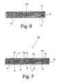
Fig. 6 shows a conventional design of a joint 61 between the first core material 4 and
the second core material 5. The joint 61 is formed in one part that is linear and runs
from the front plate 2 to the back plate 3 at an angle of 90 degrees in relation to the
front plate 2 and the back plate 3.
-
Fig. 7 shows a sandwich panel 70 with different types of core joints 71, 72, 73, 74
between parts of core materials 4, 5 where each of the. core joints 71, 72, 73, 74 is
provided with at least one reinforcing patch 9.
-
The following description of examples relates to Figs. 8-12.
Example 1: Finite Element Analysis of the stresses in the vicinity of joints of different
core materials in sandwich panels
-
The sandwich panel shown in Fig. 8 consists of two aluminium face plates and two
types of PVC core materials, i.e. Divinycell H60 and Divinycell H200 (DIAB AB
Group).
-
Divinycell H60 constitutes the middle part of the panel, while Divinycell H200
constitutes its edges. The mechanical characteristics of the panel constituents are given
in the table below.
| Modulus of elasticity of aluminium face plates | 70 GPa |
| Modulus of elasticity of a softer core, Divinycell H60 | 60 MPa |
| Modulus of elasticity of a stiffer core, Divinycell H200 | 290 MPa |
-
The panel is simply supported at its ends and centrally loaded with a force P=20
N/mm.
-
Various shapes of the core joints are considered as illustrated in Fig. 8. They are a
conventional 90 degrees joint as well as circular, 45° and V-formed joints.
-
The largest bending moment is in the middle of the panel at x=0 and decreases linearly
to the edges (where x=230 mm). If local effects in the vicinity of joints of different
core materials are disregarded, the same behaviour for the normal stresses in the face
plates of the panel would be expected: the face stresses are highest in the middle and
decrease linearly to zero at the edges of the panel.
-
Fig. 9 illustrates calculated stresses in the upper loaded (front) and lower (back) face
plates in the vicinity of the joint situated at a distance of 120 mm from the loading
point. Note that the front face is in compression (lower family of curves in Fig. 9) and
the back face is in tension.
-
For each face plate there are two curves: one describes the stresses at the outer surface
of the face, and the second describes the stresses at the face-core interface. The
difference between the outer and inner stresses is not large because of a fairly thin
thickness of each face plate, but this tendency is violated at the core joints where local
peaks of the face stresses are observed.
-
According to the classic approach one would expect stresses σxx ~ ±100 MPa at
distance of 120 mm, but they achieve values of ±170 MPa due to the discrepancy
between the elastic properties of the cores at the joint.
-
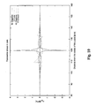
Similar local effects are present in the core of the panel, the most conspicuous of these
being the normal stresses occurring in the core when different core materials are
joined together. This is shown in Fig. 10 with regard to the upper and lower face-core
interfaces. The joints of different cores give rise to transverse normal stresses in the
core that would be completely absent in a panel having a uniform core.
-
Note that in areas far from the joint, both in the soft and stiff cores, i.e. x<95 mm and
x>145 mm, the transverse stresses are eliminated.
-
The transverse normal stresses in the core constitute a very critical point in the
sandwich panel because they may initiate a delamination of the face plate and the core,
which will jeopardize the integrity of the structure.
-
The shape of the joint has a very large effect on the maximum value of the normal
stresses in the core, as illustrated in Fig. 10.
-
Both a wedge joint of 26.6 degrees and a circular joint allow the maximum value of
σyy to be no larger than 0.5 MPa, which is 7 times smaller than the maximum stress of
3.6 MPa in the conventional 90 degrees joint.
Example 2: Experimental study of the maximum strength of sandwich panels with 90
degrees joints and sandwich panels with reinforcing patches in the joints
-
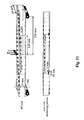
Two types of sandwich panels were experimentally studied in a static three-point
bending, one panel having a 90 degrees joint and the second panel having a 90 degrees
joint with reinforcing patches, cf. Fig. 11.
-
Face plates made of aluminium 7075-T6 (Aluminium Company of America).
Divinycell H60 constitute the middle part of the panel, while Divinycell H200 (DIAB
AB Group) makes up its edges.
-
All geometric parameters of the panels are given in Fig. 11. Their mechanical
characteristics appear from the table above.
-
Two-component epoxy resin adhesive system Araldite® 2000 (Huntsman Advanced
Materials) was used both for the attachment of the face plates to the core, and for
adjoining different core materials at the joints.
-
Reinforcing patches were produced by machining segment-like grooves at the joints
and by filling them with the same adhesive.
-
In the experiment, the panels were subjected to a central load P until they broke.
Loading velocity was 0.05 mm/sec.
-
Three panels of each type were manufactured, and their maximum strength was
assessed by recording the applied load and displacement of the central part of the
panel.
-
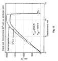
The average characteristics of the panels having 90 degrees joints and the panels
having reinforced joints are shown in Fig. 12.
-
The maximum critical load for the panel with reinforced joints is approximately 10%
higher than is the case for a conventional panel
-
It should be mentioned that the fracture in the case of the panels having a 90 degrees
joint always started from the joint, while the presence of the reinforcing patches forced
fractures to start in the softer core material and at higher loads.
-
This proves that the junction is a vulnerable element in a sandwich structure, but it can
be reinforced by simple local strengthening of the faces at the spots neighbouring the
core joints.
-
Note that shape and dimensions of the reinforcing patches were not optimised. This
can be done by using for example Finite Element Analysis, whereby the static critical
strength of the sandwich panel can be further increased.
Materials of the invention
-
Below follows examples of materials suitable for use with the invention.
Non-exclusive list of widely used types of face plate materials
-
- Steel and steel alloys.
- Stainless steel.
- Aluminium and its alloys.
- Titanium and its alloys.
- Plywood.
- Polymer materials.
- Polymer-based fibre-reinforced materials.
- Glass-fibre reinforced polymers (so-called GFRPs).
- Carbon-fibre reinforced polymers (so-called CFRPs).
- Aramid (Kevlar)-fibre reinforced polymers.
- Fibre-reinforced polymers with combinations of the fibre types and systems
mentioned above (so-called hybrid composite materials).
-
The polymer-based fibre-reinforced materials mentioned are provided by a large
number of different manufactures under a very large number of names and trade
marks. In addition, the aforementioned fibrous composite materials systems can be
manufactured using several fundamentally different manufacturing/processing
techniques including hand lay-up, prepreg technology and various resin moulding
transfer (RTM) and vacuum-assisted resin moulding transfer (VARTM) techniques.
Examples of commercially available face plate composite material systems:
-
- Glass-fibre reinforced laminates (fabrics/mats) from Ahlstrom Corp.
- Prepregs (reinforced Aramid, Carbon, Glass fibres/fabrics into which a pre-catalysed
resin system has been impregnated by a machine) from SP Systems.
- SPRINT® glass and carbon fibre composite systems from SP Systems.
- Prepreg systems with carbon, aramid or glass-fibre embedded in epoxy, phenolic,
bismaleimide (BMI) or cyanate polymer resins from Hexcel Composites.
- Prepreg and fibre (carbon/graphite, glass, aramid) and resin material (epoxy,
phenolic, thermoplastic) systems from Owens Corning.
Non-exclusive list of widely used types of core materials:
-
- Aluminium honeycomb core materials.
- Aramid honeycomb core materials.
- Polymeric foam core materials including:
- Cross-linked and linear PVC foams.
- Polymethacrylimide (PMI) foams.
- Polyurethane foams.
- Balsa wood core materials.
Examples of commercially available sandwich core materials:
-
- Divinycell® , Klegecell® , PVC and polyurethane polymers based foams from DIAB
AB Group.
- ProBalsa®, end-grain balsa woods from DIAB AB Group.
- CoreCell®, styreneacrylonitrile polymer based foams from SP Systems.
- DuraKore™, SuperLite™ - end-grain balsa wood from Alcan Airex Baltek Corp.
- Rohacell® PMI foam core from Rohm GmbH & Co. KG.
- HexWeb® aluminium honeycomb core materials from Hexcel Composites.
- Nomex® aramid honeycomb core materials from DuPont.
- PAMG-XR1 5052, 5056, 3003, aluminium honeycomb core from PLASCORE.
- PP30, PP40, polypropylene honeycomb core from PLASCORE.
- DUFAYLITE, paper honeycomb from DUFAYLITE.
- TRICEL, phenolic resin impregnated paper honeycomb from TRICEL
Honeycomb Corp.
- Lantor Coremat, nonwoven core from Lantor BV.
Non-exclusive list of widely used types of structural adhesives:
-
- Epoxy
- Polyurethane
- Polyester
- Cyanoacrylate
- Phenolic
- Acrylic.
-
Structural adhesive materials systems are provided from a very large number of
manufacturers that produce and market an even larger number of commercial
adhesive systems based on many different polymers systems and technologies.
Examples of commercially available adhesive material systems:
-
- Araldite® epoxy-based adhesive systems from Huntsman Advanced Materials.
- Redux® vinyl phenolic and epoxy-based adhesive systems from Hexcel
Composites.
- CORE-BOND®, POLY-BOND®, POLY-FAIR®, polyester-based from SP
Systems.
- Pro-Bond, Divilette ® , polyester-based from DIAB AB Group.
- SUPRASEC® and DALTOREZ®, polyurethane-based from Huntsman Advanced
Materials (under the names JEFFOL® and RUBINATE® in America).
- Methacrylate based adhesives from EpoxySystems™.
- SikaFlex® and SikaForce® polyurethane adhesives from Sika AG.
- FM-series® of epoxy-based adhesive film systems from American Cyanamide.
- 3M™ product range of acrylic-based structural adhesives from SysCon
Technology Inc.