EP1533770A1 - Connection module for connecting a sensor to a field bus - Google Patents
Connection module for connecting a sensor to a field bus Download PDFInfo
- Publication number
- EP1533770A1 EP1533770A1 EP04021024A EP04021024A EP1533770A1 EP 1533770 A1 EP1533770 A1 EP 1533770A1 EP 04021024 A EP04021024 A EP 04021024A EP 04021024 A EP04021024 A EP 04021024A EP 1533770 A1 EP1533770 A1 EP 1533770A1
- Authority
- EP
- European Patent Office
- Prior art keywords
- sensor
- connection module
- circuit
- interface
- operating parameters
- Prior art date
- Legal status (The legal status is an assumption and is not a legal conclusion. Google has not performed a legal analysis and makes no representation as to the accuracy of the status listed.)
- Granted
Links
- 238000000034 method Methods 0.000 claims abstract description 13
- 238000004891 communication Methods 0.000 claims description 14
- 230000005693 optoelectronics Effects 0.000 claims description 10
- 238000006243 chemical reaction Methods 0.000 description 6
- 230000005540 biological transmission Effects 0.000 description 4
- 230000007547 defect Effects 0.000 description 3
- 230000006978 adaptation Effects 0.000 description 2
- 238000011161 development Methods 0.000 description 2
- 230000003287 optical effect Effects 0.000 description 2
- 238000012549 training Methods 0.000 description 2
- 238000012546 transfer Methods 0.000 description 2
- 230000000295 complement effect Effects 0.000 description 1
- 230000009849 deactivation Effects 0.000 description 1
- 238000010586 diagram Methods 0.000 description 1
- 230000000694 effects Effects 0.000 description 1
- 230000010354 integration Effects 0.000 description 1
- 238000005259 measurement Methods 0.000 description 1
- 230000006855 networking Effects 0.000 description 1
- 230000000717 retained effect Effects 0.000 description 1
- 238000005476 soldering Methods 0.000 description 1
- 230000001502 supplementing effect Effects 0.000 description 1
- 238000013519 translation Methods 0.000 description 1
Images
Classifications
-
- G—PHYSICS
- G05—CONTROLLING; REGULATING
- G05B—CONTROL OR REGULATING SYSTEMS IN GENERAL; FUNCTIONAL ELEMENTS OF SUCH SYSTEMS; MONITORING OR TESTING ARRANGEMENTS FOR SUCH SYSTEMS OR ELEMENTS
- G05B19/00—Programme-control systems
- G05B19/02—Programme-control systems electric
- G05B19/04—Programme control other than numerical control, i.e. in sequence controllers or logic controllers
- G05B19/042—Programme control other than numerical control, i.e. in sequence controllers or logic controllers using digital processors
- G05B19/0423—Input/output
-
- G—PHYSICS
- G05—CONTROLLING; REGULATING
- G05B—CONTROL OR REGULATING SYSTEMS IN GENERAL; FUNCTIONAL ELEMENTS OF SUCH SYSTEMS; MONITORING OR TESTING ARRANGEMENTS FOR SUCH SYSTEMS OR ELEMENTS
- G05B2219/00—Program-control systems
- G05B2219/20—Pc systems
- G05B2219/25—Pc structure of the system
- G05B2219/25006—Interface connected to fieldbus
Definitions
- connection module for connecting a sensor, in particular an optoelectronic sensor, to a fieldbus, with a sensor interface for connecting the connection module with an interface of a sensor, a serial bus interface to the Connecting the connection module to an interface of a fieldbus, and a gateway circuit connected to the bus interface and the sensor interface is connected to receive at the bus interface Convert data into a data format of a connected sensor and at the sensor interface, and at the sensor interface received data in a data format of the fieldbus convert and output to the bus interface.
- Background of the invention is the networking of sensors, for example of one-dimensional or two-dimensional optical code readers or from laser measurement systems, via a digital fieldbus, for example of type Profibus or DeviceNet.
- a digital fieldbus for example of type Profibus or DeviceNet.
- the sensors with to provide a separate fieldbus interface, which is a connection of the Sensors to the fieldbus and a communication between the sensor and the fieldbus enabled.
- a fieldbus interface integrated into the sensor makes the actual sensor module but undesirable expensive and undesirably bulky for some applications.
- the sensor in question is indeed adapted to a specific fieldbus; However, the sensor is no longer readily available for other fieldbus types use.
- connection module that has a sensor interface owns that connect to a serial port allows the sensor.
- the connection module is with a so-called Gateway circuit connected to the sensor interface of the Connection module exchanged data in the format of the fieldbus translated and vice versa, and for this purpose via a bus interface connected to the fieldbus.
- the connection module and the gateway circuit thus serve to adapt both the hardware (respective Interface) as well as the data formats (bus protocol) between Fieldbus and sensor, the gateway circuit usually a serial sensor interface adapted to a specific fieldbus type.
- the user must parameterize two devices, namely the sensor and the intermediary gateway circuit.
- connection modules are particularly suitable for optoelectronic Sensors as inadequate, as these in addition to a serial Data interface digital switching inputs and outputs own and there Therefore, additional interconnections are required to achieve the desired To effect adaptation to a particular fieldbus. It is also at the known connection modules the parameterization, i. the adaptation the gateway circuit to the fieldbus addressing and the fieldbus protocol undesirably expensive, since two devices (sensor and gateway circuit) need to be addressed.
- connection module with the characteristics of the Claim 1, and in particular in that the sensor interface as a parallel interface with a serial data interface and at least one separate, parallel switching input / output is formed, and that in the connection module, an I / O circuit integrated with the bus interface and the sensor interface is connected to receive serially at the bus interface To convert switching data into switching signals and to the parallel Output switching input / output of the sensor interface, and on received in parallel to the switching input / output of the sensor interface Converting switching signals into switching data and at the bus interface output serially.
- connection module is thus characterized by the fact that the sensor interface is designed as a parallel interface, in addition to the usual serial data interface at least one parallel thereto Has switching input and / or output. Furthermore, the connection module provided with a so-called I / O circuit. This translates Switching data in the at the bus interface of the connection module received serial data word (string) are included in digital Switching signals directly via the parallel switching input / output of the Sensor interface are transmitted to a connected sensor can. Also in the opposite direction provides the in the connection module integrated I / O circuit for converting digital switching signals, at the parallel switching input / output of the sensor interface received from a connected sensor, into a data word, that at the (only) serial bus interface together with output the sensor data received at the serial data interface can be.
- the also included in the connection module Gateway circuitry ensures the required conversion of the serial sensor data between the bus interface and the serial Data interface of the sensor interface are exchanged.
- connection module By connecting the connection module with one or more additional parallel Switching inputs / outputs is equipped and in the connection module integrated at least one I / O circuit, which eliminates the Need for separate I / O modules in parallel with a conventional one Connection module with digital switching inputs / outputs of the sensor on the one hand and the fieldbus on its own On the other hand, the fieldbus interface must be connected. Furthermore eliminates the need for such additional I / O modules for the specific to configure the fieldbus used.
- the sensor is according to the invention So over a single connection module with integrated gateway circuit and integrated I / O circuit connected to the fieldbus. The switching signals of the sensor can in this way directly in the process image the controller can be considered and used, so that the control of the switching inputs / outputs of the sensor significantly simplified.
- the equipment cost is considerably reduced, since only a single connection module required to connect the relevant sensor to the fieldbus even if the sensor has one or more switch inputs / outputs has, as with optoelectronic sensors typically the case is.
- connection module Since the I / O circuit is integrated into the connection module, there is a connection between the switching inputs / outputs of the sensor and the I / O switching particularly easy over very short lines possible.
- connection module or the connected sensor is possible in a simple manner, as for the Required parameterization of the replaced device None additional, separate I / O modules must be considered.
- connection module is the at least one I / O circuit integrated into the gateway circuit, i. the I / O circuit is part of the gateway circuit. In this case is omitted So even the need to use the I / O circuit as a separate circuit unit or board, but the conversion of the serial Switching data in parallel switching signals - and vice versa - is done by a common gateway I / O circuit.
- the connection of the I / O circuit with the bus interface and the sensor interface runs in in this case via the actual gateway circuit.
- the gateway circuit as one of the User replaceable unit is designed, in particular as a Plug-in card, which can additionally be secured by screws.
- a plug-in card which can additionally be secured by screws.
- the connection module due to the modular structure especially be flexibly adapted to different fieldbus types. in the In case of a defect of the circuit in question, this may be particularly easily replaced without having to replace the entire connection module must become.
- the sensor interface, the bus interface, the gateway circuit and the I / O circuit of the connection module housed in a common housing.
- connection module Furthermore, a permanent memory for storing operating parameters based on which the gateway circuit and the I / O circuit can communicate with the fieldbus.
- Permanent memory remain the required operating parameters, For example, the identification number of the connected sensor within the network, the data length or the data to be used using baud rate, always stored as long as the stored Parameters can not be overridden. This leaves the Operating parameters obtained even when the system is temporarily shut down or the assigned sensor is replaced.
- the non-volatile memory as a user replaceable unit is formed, for example as removable memory card.
- the Connection module with associated gateway circuit and / or I / O circuit being exchanged, with those for communicating with receive the required fieldbus operating parameters in a simple manner remain, by the non-volatile memory from the replaced connection module removed and inserted into the new connection module becomes.
- the non-volatile memory with its own microcontroller provided that a direct data exchange of the permanent memory with the serial data interface of the connection module.
- non-volatile memory can also be used directly with the gateway circuit and the I / O circuit.
- the gateway circuit and The I / O circuitry is configured to be used for communication Operating parameters to be used with the fieldbus from a connected Sensor via the sensor interface to the gateway circuit and can be communicated to the I / O circuit.
- This training can thus be used for communication with the Fieldbus required operating parameters of the connected Transmit sensor to the active circuits of the connection module become.
- the user does not have to parameterize two devices, but it is sufficient, the required operating parameters only to adjust on the sensor. From this become the operating parameters to the gateway circuit and the I / O circuit of the connection module transfer.
- the parameterization can thus - for the sensor and the Connection module in common - in a simple way within the user interface of the connected sensor.
- the gateway circuit including the I / O circuit connected to the sensor interface such that the Operating parameters automatically at startup - and in particular during a limited parameterization time interval after start of operation - read in at the sensor interface of the connection module become.
- the gateway circuit and the I / O circuit configured so that after startup a data connection between the sensor interface of the connection module and the connected sensor can be built to operating parameters from the sensor to the connection module.
- Relevant Event for the transmission of the operating parameters may be the start of operation be the connection module and / or the connected sensor; if both devices are not switched on at the same time, the transmission takes place especially when starting the device later switched on.
- connection module with one or the already mentioned permanent memory is provided in which the over the sensor interface received operating parameters can be stored.
- This permanent memory can be used directly with the sensor interface or indirectly via the gateway circuit and the I / O circuit with the Sensor interface be connected.
- the non-volatile memory can be configured such that immediately after the start of the connection module and before one Transmission of operating parameters from the connected sensor those operating parameters stored in the non-volatile memory are from the non-volatile memory via the sensor interface to the connected sensor are transmitted.
- the stored operating parameters from the non-volatile memory indirectly via the sensor interface and the connected sensor to the Gateway circuit and the I / O circuit are transmitted.
- Thereby can be a direct interconnection between permanent memory on the one hand and gateway circuit and I / O circuit on the other hand omitted.
- the gateway circuit and the I / O circuit be configured in such a way that, if after a Operating start of the connection module no operating parameters of the connected sensor are received, those operating parameters for communication with the fieldbus in the non-volatile memory stored before the last start of operation of the connection module have been. So if the connection module after startup exceptionally no operating parameters from a connected Sensor receives, the connection module communicates with the fieldbus due to the last received and stored operating parameters. This makes it possible, for example, a previously connected Sensor through a simple switching unit or a simple actuator which is not used to initialize the connection module or the Permanent memory are designed with operating parameters. Yet such simple units can after exchange with the fieldbus communicate because the connection module of the communication is now the previously transmitted and stored operating parameters based sets.
- the invention also relates to a method for connecting a Sensor, in particular an optoelectronic sensor, via a connection module to a fieldbus, in which a to a connection module connected sensor via a sensor interface of the connection module Operating parameters to a gateway circuit of the connection module and in which the gateway circuit is based on the the operating parameter transmitted to the sensor communicates with the fieldbus, where the connection module is not necessarily with an I / O circuit must be equipped.
- connection module makes it possible, similar to the explained training of the connection module, that the user is basically not the Parameterize the connection module and a connected sensor separately got to. Rather, it is sufficient if the user over the already provided user interface the connected sensor parameterized, i. with those required for communication with the fieldbus Provides operating parameters. These operating parameters can then from the sensor via the sensor interface of the connection module to the gateway circuit, including any I / O circuitry of the connection module.
- an identification number of the sensor within the network or fieldbus system may be at the mentioned operating parameters for example, an identification number of the sensor within the network or fieldbus system to one to be used Data length or to act at a baud rate to be used.
- the operating parameters of the connected Sensor to the gateway circuit of the connection module at startup of the connection module or the sensor is transmitted automatically, the Gateway circuit, the sensor interface in particular only during a limited parameterization time interval from the start of operation queries.
- Relevant event for the transmission of operating parameters can also be the start of operation of the connection module and / or the be connected sensor; if both devices are not switched on at the same time be, the transfer takes place especially at startup of the later switched on device.
- the operating parameters transmitted by the sensor stored in a non-volatile memory of the connection module.
- the operating parameters transmitted by the sensor stored in a non-volatile memory of the connection module.
- those operating parameters already in the non-volatile memory of the connection module are stored by the non-volatile memory be transmitted to the connected sensor.
- connection module uses the last one received and stored operating parameters if no after a restart new operating parameters are received at the sensor interface.
- a simple unit such as an I / O circuit or an actuator that has been replaced, which has no initialization of the connection module with operating parameters permitted.
- the unit in question can still use the fieldbus without further Parametritationshunt be addressed, since the connection module fall back on the last stored operating parameters can.
- connection module it is in the illustrated method also advantageous if the operating parameters in a user-changeable permanent memory of the connection module are stored.
- the used connection module can be replaced without a reparameterization is required because the non-volatile memory with replaced the previously used operating parameters and thus in can be used with the new connection module.
- Fig. 1 shows a block diagram of a connection module 11 with a serial bus interface 13 and a parallel sensor interface 15. This has a serial data interface 17 and - parallel to this - a switching input 19 and a switching output 21.
- the connection module 11 is via the bus interface 13 with a field bus 23, for example connected to the type Profibus or DeviceNet. Furthermore, the connection module 11 via the serial data interface 17 and via the Switching input 19 and the switching output 21 of the sensor interface 15th with an optoelectronic sensor 25, for example an optical Code reader connected.
- connection module 11 has a gateway circuit 27, the with the bus interface 13 and the serial data interface 17 of the Sensor interface 15 is connected.
- the gateway circuit 27 is used for Conversion between the bus interface 13 and the sensor interface 15 exchanged data in the respective data format, such as will be explained below.
- an I / O circuit 29 which for conversion specifically between the bus interface 13 and the Switching input 19 and switching output 21 exchanged switching data or Switching signals is used, as will also be explained below.
- the I / O circuit 29 is for this purpose indirectly via the gateway circuit 27 on the one hand with the bus interface 13 and the other with the switching input 19 and the switching output 21 of the sensor interface 15 connected.
- connection module 11 has an optional permanent memory 33 for storing operating parameters.
- the permanent memory 33 is connected to the serial data interface 17 of the sensor interface 15 connected. Alternatively or additionally, the permanent memory 33 However, also be connected directly to the gateway circuit 27.
- I / O circuit 29 can also have multiple I / O circuits be provided according to the number of switching inputs / outputs 19, 21.
- connection module 11 is further provided with a power supply not shown in FIG provided, for example, it is a 24V power supply can act.
- a power supply not shown in FIG provided, for example, it is a 24V power supply can act.
- the Connection between the connection module 11 and the sensor 25 takes place over a single common harness.
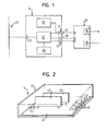
- connection module 11 shows a possible embodiment of the connection module 11 according to Fig. 1 in a schematic perspective view.
- one passive motherboard 41 provided on the one interchangeable by the user Plug-in board 43 is mounted, both the gateway circuit 27th as well as the I / O circuit 29 of FIG. 1 including a microcontroller contains.
- the non-volatile memory 33 according to Fig. 1 carries together with an associated microcontroller.
- the motherboard 41 is provided with a serial connector 47, serving as the bus interface 13 of FIG. 1, and with parallel clamp connectors 49 provided as a serial data interface 17 or Switching input 19 and switching output 21 of the sensor interface 15 according to Fig. 1 serve.
- the motherboard 41 connects the contacts for the gateway I / O plug-in board 43, the contacts for the optional non-volatile memory card 45, the serial connector 47 and the parallel clamp connectors 49 via in Fig. 2, not shown interconnects.
- the motherboard 41, the gateway I / O board 43, the permanent memory card 45, the serial connector 47 and the parallel clamp connectors 49 are within a common housing 51 arranged in the view of FIG. 2 at the top and on the both sides facing the viewer is open.
- connection module 11 is therefore essentially one passive module with an active gateway I / O board 43 and an active non-volatile memory card 45.
- connection module 11 shown in FIGS. 1 and 2 serves for connection of the sensor 25 to the field bus 23.
- the connection module is used 11 as an adapter between the parallel interface of the sensor 25 and the serial interface of the field bus 23.
- connection module 11 On the other takes place within the connection module 11, a translation of the at Sensor interface 15 with the sensor 25 exchanged data in the Format of the data exchanged at the bus interface 13, and vice versa. This mutual data conversion takes place in the gateway circuit 27th
- a gateway circuit usually a serial data interface (Interface 17) adapted to a bus system, is complementary to the gateway circuit 27 at least one I / O circuit 29 is provided, the additionally integrated into the connection module 11.
- the I / O circuit 29 So allows the direct communication of the fieldbus 23 with the Switch inputs / outputs of the sensor 25.
- the I / O circuit 29 communicates indirectly for this purpose via the gateway circuit 27 with the bus interface 13 and with the switching input 19 and the switching output 21, wherein alternatively also a direct connection with the interfaces 13, 19, 21 may be provided can.
- connection module shown in FIGS. 1 and 2 11 A particular advantage of the connection module shown in FIGS. 1 and 2 11 is that this due to the integrated I / O circuit 29 a connection of the serial field bus 23 to the parallel interface the sensor 25 allows, in addition to the actual connection module 11 additional I / O modules are required between the Sensor 25 and the field bus 23 are to be interconnected.
- the I / O circuit 29 assumes within the connection module 11, the conversion of the bus interface 13 serially received switching data in digital switching signals for the parallel switching inputs / outputs 19, 21, and vice versa.
- the digital switching signals can thereby be stored in the process image of the used fieldbus 23 can be easily controlled without that additional I / O modules are needed separately for the specific one Fieldbus 23 must be parameterized.
- the combination of sensor 25 and connection module 11 with gateway circuit 27 and I / O circuit 29 appears to the user as a single device, wherein both the sensor 25 and the gateway circuit 27 and the I / O circuit 29 together within the user interface of the sensor 25th can be parameterized.
- gateway circuit 27 and the I / O circuit 29 in the connection module 11 are installed (plug board 43 in Fig. 2), is a special Short cable connection to the parallel clamp connectors 49 and thus to the switching inputs / outputs of the sensor 25 possible.
- connection module 11 can easy to adapt to different fieldbus systems, and the relevant connection module 11 with the other components can be used flexibly for different fieldbus systems.
- the optional permanent memory 33 allows non-volatile storage from the operating parameters, the identification of the connected Enable sensors 25 through the field bus 23 and the nature of Set communication with the fieldbus 23.
- the connection module 11 is equipped with such a permanent memory 33, stand these operating parameters even after an intermediate deactivation of the connection module 11 available, so that after a Switch off and a renewed switching on the connection module 11th no reparameterization is required. Since the permanent memory 33 in Form of a user replaceable plug-in card 45 is present, can the connection module 11, for example, in the case of a defect on especially easy way to be exchanged, as by taking over the Permanent memory card 45 in the new connection module the required Operating parameters are retained.
- the parameterization of the gateway circuit 27 and the I / O circuit 29 with the aid of the permanent memory 33 can in the following manner respectively:
- the sensor 25 After a start of operation of the connection module 11 - and due to the common voltage supply also of the connected sensor 25 - is via the serial data interface 17 of the sensor interface 15th during a limited parameterization time interval a connection between the sensor 25 and the permanent memory 33 of the connection module 11 built.
- the sensor 25 detects whether he is using a Connected connection module 11 and whether a permanent memory 33 with valid operating parameters. If applicable, he reads Sensor 25, the operating parameters via the sensor interface 15 from the Permanent memory 33 and transmits the operating parameters - again via the sensor interface 15 - to the gateway circuit 27 inclusive the I / O circuit 29. It can meantime within the sensor 25, a check, an additional storage and / or a supplementing of the operating parameters.
- the sensor 25 If the sensor 25, however, despite its connection to the non-volatile memory 33 receives no operating parameters from this - for example due to a defect of the permanent memory 33-, it transmits to the gateway circuit 27 including the I / O circuit 29 those Operating parameters, the sensor 25 in its own non-volatile Memory has saved.
- the gateway circuit 27 of the connection module 11th none during the parameterization time interval after a start of operation Operating parameters on the serial data interface 17 from the sensor 25, it reads from the non-volatile memory 33 the last stored and used operating parameters and uses them for the communication with the fieldbus 23.
- the user does not need two or parameterize more devices separately to the system for the connection to be configured with the fieldbus 23. Instead, it is enough if the user only the sensor 25 within its user interface initialized with the operating parameters. In case of an exchange of the Sensor 25 is also no re-parameterization required because the previously transmitted to the gateway circuit 27 of the connection module 11 and stored there in non-volatile memory 33 operating parameters can be used further.
- connection module 11 via no permanent memory 33rd it is possible that automatically after a reboot of the system, preferably only during a limited parameterization time interval, from the connected sensor 25 via the serial data interface 17 of the sensor interface 15 stored in the sensor 25 Operating parameters to the gateway circuit 27 and optionally be transferred to the I / O circuit 29. In this case, too This results in the advantage that the user does not both the Sensor 25 and the gateway circuit 27 of the connection module 11th must parameterize separately.
Abstract
Description
Die Erfindung betrifft'ein Anschlussmodul zum Anschließen eines Sensors, insbesondere eines optoelektronischen Sensors, an einen Feldbus, mit einer Sensorschnittstelle zum Verbinden des Anschlussmoduls mit einer Schnittstelle eines Sensors, einer seriellen Busschnittstelle zum Verbinden des Anschlussmoduls mit einer Schnittstelle eines Feldbusses, und einer Gateway-Schaltung, die mit der Busschnittstelle und der Sensorschnittstelle verbunden ist, um an der Busschnittstelle empfangene Daten in ein Datenformat eines angeschlossenen Sensors zu konvertieren und an der Sensorschnittstelle auszugeben, und um an der Sensorschnittstelle empfangenen Daten in ein Datenformat des Feldbusses zu konvertieren und an der Busschnittstelle auszugeben.The invention relates to a connection module for connecting a sensor, in particular an optoelectronic sensor, to a fieldbus, with a sensor interface for connecting the connection module with an interface of a sensor, a serial bus interface to the Connecting the connection module to an interface of a fieldbus, and a gateway circuit connected to the bus interface and the sensor interface is connected to receive at the bus interface Convert data into a data format of a connected sensor and at the sensor interface, and at the sensor interface received data in a data format of the fieldbus convert and output to the bus interface.
Hintergrund der Erfindung ist die Vernetzung von Sensoren, beispielsweise von eindimensionalen oder zweidimensionalen optischen Codelesern oder von Lasermesssystemen, über einen digitalen Feldbus, beispielsweise vom Typ Profibus oder DeviceNet. Hierfür ist es bekannt, die Sensoren mit einer eigenen Feldbusschnittstelle zu versehen, die ein Anschließen des Sensors an den Feldbus und eine Kommunikation zwischen dem Sensor und dem Feldbus ermöglicht. Eine in den Sensor integrierte Feldbusschnittstelle macht das eigentliche Sensormodul jedoch unerwünscht teuer und für manche Anwendungen unerwünscht voluminös. Außerdem ist der betreffende Sensor zwar an einen bestimmten Feldbus angepasst; der Sensor lässt sich jedoch nicht mehr ohne weiteres für andere Feldbustypen verwenden. Background of the invention is the networking of sensors, for example of one-dimensional or two-dimensional optical code readers or from laser measurement systems, via a digital fieldbus, for example of type Profibus or DeviceNet. For this it is known, the sensors with to provide a separate fieldbus interface, which is a connection of the Sensors to the fieldbus and a communication between the sensor and the fieldbus enabled. A fieldbus interface integrated into the sensor makes the actual sensor module but undesirable expensive and undesirably bulky for some applications. Furthermore the sensor in question is indeed adapted to a specific fieldbus; However, the sensor is no longer readily available for other fieldbus types use.
Alternativ zu einer eigenen Feldbusschnittstelle ist es bekannt, den betreffenden Sensor mit einem Anschlussmodul zu versehen, das eine Sensorschnittstelle besitzt, die eine Verbindung mit einer seriellen Schnittstelle des Sensors ermöglicht. Das Anschlussmodul ist mit einer so genannten Gateway-Schaltung verbunden, die die an der Sensorschnittstelle des Anschlussmoduls ausgetauschten Daten in das Format des Feldbusses übersetzt und umgekehrt, und die zu diesem Zweck über eine Busschnittstelle mit dem Feldbus verbunden ist. Das Anschlussmodul und die Gateway-Schaltung dienen somit zur Anpassung sowohl der Hardware (jeweilige Schnittstelle) als auch der Datenformate (Busprotokoll) zwischen Feldbus und Sensor, wobei die Gateway-Schaltung üblicherweise eine serielle Sensorschnittstelle an einen bestimmten Feldbustyp adaptiert. Um den Sensor für den Feldbus zu konfigurieren und eine Kommunikation mit dem Feldbus zu ermöglichen, muss der Anwender zwei Geräte parametrieren, nämlich den Sensor und die zwischengeschaltete Gateway-Schaltung.As an alternative to a separate fieldbus interface, it is known that the respective Sensor to be provided with a connection module that has a sensor interface owns that connect to a serial port allows the sensor. The connection module is with a so-called Gateway circuit connected to the sensor interface of the Connection module exchanged data in the format of the fieldbus translated and vice versa, and for this purpose via a bus interface connected to the fieldbus. The connection module and the gateway circuit thus serve to adapt both the hardware (respective Interface) as well as the data formats (bus protocol) between Fieldbus and sensor, the gateway circuit usually a serial sensor interface adapted to a specific fieldbus type. Around configure the sensor for the fieldbus and communication with the fieldbus, the user must parameterize two devices, namely the sensor and the intermediary gateway circuit.
Bekannte Anschlussmodule erweisen sich insbesondere bei optoelektronischen Sensoren als unzureichend, da diese zusätzlich zu einer seriellen Datenschnittstelle digitale Schalteingänge und -ausgänge besitzen und da deshalb zusätzliche Verschaltungen erforderlich sind, um die gewünschte Anpassung an einen bestimmten Feldbus zu bewirken. Außerdem ist bei den bekannten Anschlussmodulen die Parametrierung, d.h. die Anpassung der Gateway-Schaltung an die Feldbus-Adressierung und das Feldbus-Protokoll unerwünscht aufwendig, da zwei Geräte (Sensor und Gateway-Schaltung) angesprochen werden müssen.Known connection modules are particularly suitable for optoelectronic Sensors as inadequate, as these in addition to a serial Data interface digital switching inputs and outputs own and there Therefore, additional interconnections are required to achieve the desired To effect adaptation to a particular fieldbus. It is also at the known connection modules the parameterization, i. the adaptation the gateway circuit to the fieldbus addressing and the fieldbus protocol undesirably expensive, since two devices (sensor and gateway circuit) need to be addressed.
Es ist deshalb eine Aufgabe der Erfindung, in einem über einen Feldbus verbundenen Sensornetzwerk die Einbindung und den Austausch von Anschlussmodulen und Sensoren zu erleichtern. It is therefore an object of the invention in one via a fieldbus connected sensor network the integration and exchange of Connection modules and sensors easier.
Diese Aufgabe wird durch ein Anschlussmodul mit den Merkmalen des Anspruchs 1 gelöst, und insbesondere dadurch, dass die Sensorschnittstelle als eine Parallelschnittstelle mit einer seriellen Datenschnittstelle und wenigstens einem separaten, hierzu parallelen Schalteingang/ausgang ausgebildet ist, und dass in das Anschlussmodul eine I/O-Schaltung integriert ist, die mit der Busschnittstelle und der Sensorschnittstelle verbunden ist, um an der Busschnittstelle seriell empfangene Schaltdaten in Schaltsignale zu konvertieren und an dem parallelen Schalteingang/-ausgang der Sensorschnittstelle auszugeben, und um an dem Schalteingang/-ausgang der Sensorschnittstelle parallel empfangene Schaltsignale in Schaltdaten zu konvertieren und an der Busschnittstelle seriell auszugeben.This task is accomplished by a connection module with the characteristics of the Claim 1, and in particular in that the sensor interface as a parallel interface with a serial data interface and at least one separate, parallel switching input / output is formed, and that in the connection module, an I / O circuit integrated with the bus interface and the sensor interface is connected to receive serially at the bus interface To convert switching data into switching signals and to the parallel Output switching input / output of the sensor interface, and on received in parallel to the switching input / output of the sensor interface Converting switching signals into switching data and at the bus interface output serially.
Dieses Anschlussmodul zeichnet sich also dadurch aus, dass die Sensorschnittstelle als eine Parallelschnittstelle ausgebildet ist, die zusätzlich zu der üblichen seriellen Datenschnittstelle wenigstens einen hierzu parallelen Schalteingang und/oder -ausgang besitzt. Ferner ist das Anschlussmodul mit einer so genannten I/O-Schaltung versehen. Diese übersetzt Schaltdaten, die in dem an der Busschnittstelle des Anschlussmoduls empfangenen seriellen Datenwort (String) enthalten sind, in digitale Schaltsignale, die direkt über den parallelen Schalteingang/-ausgang der Sensorschnittstelle an einen angeschlossenen Sensor übermittelt werden können. Auch in umgekehrter Richtung sorgt die in das Anschlussmodul integrierte I/O-Schaltung für eine Konvertierung von digitalen Schaltsignalen, die an dem parallelen Schalteingang/-ausgang der Sensorschnittstelle von einem angeschlossenen Sensor empfangen werden, in ein Datenwort, das an der (einzigen) seriellen Busschnittstelle gemeinsam mit den an der seriellen Datenschnittstelle empfangenen Sensordaten ausgegeben werden kann. Die ebenfalls in dem Anschlussmodul enthaltene Gateway-Schaltung sorgt dabei für die erforderliche Umwandlung der seriellen Sensordaten, die zwischen der Busschnittstelle und der seriellen Datenschnittstelle der Sensorschnittstelle ausgetauscht werden.This connection module is thus characterized by the fact that the sensor interface is designed as a parallel interface, in addition to the usual serial data interface at least one parallel thereto Has switching input and / or output. Furthermore, the connection module provided with a so-called I / O circuit. This translates Switching data in the at the bus interface of the connection module received serial data word (string) are included in digital Switching signals directly via the parallel switching input / output of the Sensor interface are transmitted to a connected sensor can. Also in the opposite direction provides the in the connection module integrated I / O circuit for converting digital switching signals, at the parallel switching input / output of the sensor interface received from a connected sensor, into a data word, that at the (only) serial bus interface together with output the sensor data received at the serial data interface can be. The also included in the connection module Gateway circuitry ensures the required conversion of the serial sensor data between the bus interface and the serial Data interface of the sensor interface are exchanged.
Indem das Anschlussmodul mit einem oder mehreren zusätzlichen parallelen Schalteingängen/-ausgängen ausgestattet ist und in das Anschlussmodul wenigstens eine I/O-Schaltung integriert ist, entfällt die Notwendigkeit von separaten I/O-Modulen, die parallel zu einem herkömmlichen Anschlussmodul mit den digitalen Schalteingängen/ausgängen des Sensors einerseits und dem Feldbus über eine eigene Feldbusschnittstelle andererseits verbunden werden müssen. Außerdem entfällt die Notwendigkeit, derartige zusätzliche I/O-Module für den speziell verwendeten Feldbus zu konfigurieren. Der Sensor wird erfindungsgemäß also über ein einziges Anschlussmodul mit integrierter Gateway-Schaltung und integrierter I/O-Schaltung an den Feldbus angeschlossen. Die Schaltsignale des Sensors können auf diese Weise direkt im Prozessabbild der Steuerung berücksichtigt und verwendet werden, so dass sich die Steuerung der Schalteingänge/-ausgänge des Sensors deutlich vereinfacht.By connecting the connection module with one or more additional parallel Switching inputs / outputs is equipped and in the connection module integrated at least one I / O circuit, which eliminates the Need for separate I / O modules in parallel with a conventional one Connection module with digital switching inputs / outputs of the sensor on the one hand and the fieldbus on its own On the other hand, the fieldbus interface must be connected. Furthermore eliminates the need for such additional I / O modules for the specific to configure the fieldbus used. The sensor is according to the invention So over a single connection module with integrated gateway circuit and integrated I / O circuit connected to the fieldbus. The switching signals of the sensor can in this way directly in the process image the controller can be considered and used, so that the control of the switching inputs / outputs of the sensor significantly simplified.
Der Geräteaufwand ist erheblich verringert, da lediglich ein einziges Anschlussmodul erforderlich ist, um den betreffenden Sensor an den Feldbus anzuschließen, selbst wenn der Sensor einen oder mehrere Schalteingänge/-ausgänge besitzt, wie dies bei optoelektronischen Sensoren typischerweise der Fall ist.The equipment cost is considerably reduced, since only a single connection module required to connect the relevant sensor to the fieldbus even if the sensor has one or more switch inputs / outputs has, as with optoelectronic sensors typically the case is.
Da die I/O-Schaltung in das Anschlussmodul integriert ist, ist eine Verbindung zwischen den Schalteingängen/-ausgängen des Sensors und der I/O-Schaltung besonders einfach über sehr kurze Leitungen möglich. Since the I / O circuit is integrated into the connection module, there is a connection between the switching inputs / outputs of the sensor and the I / O switching particularly easy over very short lines possible.
Auch ein eventuell erforderlicher Austausch des Anschlussmoduls oder des angeschlossenen Sensors ist auf einfache Weise möglich, da für die hierzu erforderliche Parametrierung des ausgetauschten Geräts keine zusätzlichen, separaten I/O-Module berücksichtigt werden müssen.Also a possibly required replacement of the connection module or the connected sensor is possible in a simple manner, as for the Required parameterization of the replaced device None additional, separate I / O modules must be considered.
Gemäß einer vorteilhaften Ausführungsform des Anschlussmoduls ist die wenigstens eine I/O-Schaltung in die Gateway-Schaltung integriert, d.h. die I/O-Schaltung ist Teil der Gateway-Schaltung. In diesem Fall entfällt also sogar die Notwendigkeit, die I/O-Schaltung als separate Schaltungseinheit bzw. -platine auszubilden, sondern die Konvertierung der seriellen Schaltdaten in parallele Schaltsignale - und umgekehrt - erfolgt durch eine gemeinsame Gateway-I/O-Schaltung. Die Verbindung der I/O-Schaltung mit der Busschnittstelle und der Sensorschnittstelle verläuft in diesem Fall über die eigentliche Gateway-Schaltung.According to an advantageous embodiment of the connection module is the at least one I / O circuit integrated into the gateway circuit, i. the I / O circuit is part of the gateway circuit. In this case is omitted So even the need to use the I / O circuit as a separate circuit unit or board, but the conversion of the serial Switching data in parallel switching signals - and vice versa - is done by a common gateway I / O circuit. The connection of the I / O circuit with the bus interface and the sensor interface runs in in this case via the actual gateway circuit.
Weiterhin ist es von Vorteil, wenn die Gateway-Schaltung als eine vom Anwender auswechselbare Einheit ausgebildet ist, insbesondere als eine Steckkarte, die zusätzlich durch Schrauben gesichert sein kann. Als eine vom Anwender auswechselbare Einheit ist im Zusammenhang mit der Erfindung generell eine Einheit zu verstehen, die entweder werkzeugfrei oder mit einfachem Werkzeug (wie beispielsweise Schraubendreher), und jedenfalls ohne Lötvorgänge ausgetauscht werden kann. Auch eine separate I/O-Schaltung oder eine kombinierte Gateway-I/O-Schaltung kann als eine vom Anwender auswechselbare Einheit ausgebildet sein. In diesen Fällen kann das Anschlussmodul aufgrund des modularen Aufbaus besonders flexibel an unterschiedliche Feldbustypen angepasst werden. Im Falle eines Defekts der betreffenden Schaltung kann diese besonders einfach ersetzt werden, ohne dass das gesamte Anschlussmodul ausgetauscht werden muss. Furthermore, it is advantageous if the gateway circuit as one of the User replaceable unit is designed, in particular as a Plug-in card, which can additionally be secured by screws. As one user replaceable unit is related to the Invention generally a unit to understand that either tool-free or with simple tools (such as screwdrivers), and in any case can be replaced without soldering. Also a separate one I / O circuit or a combined gateway I / O circuit can be designed as a user replaceable unit. In these Cases, the connection module due to the modular structure especially be flexibly adapted to different fieldbus types. in the In case of a defect of the circuit in question, this may be particularly easily replaced without having to replace the entire connection module must become.
Weiterhin ist es bevorzugt, wenn die Sensorschnittstelle, die Busschnittstelle, die Gateway-Schaltung und die I/O-Schaltung des Anschlussmoduls in einem gemeinsamen Gehäuse untergebracht sind.Furthermore, it is preferred if the sensor interface, the bus interface, the gateway circuit and the I / O circuit of the connection module housed in a common housing.
Gemäß einer vorteilhaften Ausführungsform ist in das Anschlussmodul ferner ein Permanentspeicher zum Speichern von Betriebsparametern integriert, auf deren Grundlage die Gateway-Schaltung und die I/O-Schaltung mit dem Feldbus kommunizieren können. Durch einen derartigen Permanentspeicher bleiben die erforderlichen Betriebsparameter, beispielsweise die Identifikationsnummer des angeschlossenen Sensors innerhalb des Netzwerks, die zu verwendende Datenlänge oder die zu verwendende Baud-Rate, stets gespeichert, solange die gespeicherten Parameter nicht gezielt neu überschrieben werden. Dadurch bleiben die Betriebsparameter erhalten, selbst wenn das System zeitweilig abgeschaltet oder der zugeordnete Sensor ausgetauscht wird.According to an advantageous embodiment is in the connection module Furthermore, a permanent memory for storing operating parameters based on which the gateway circuit and the I / O circuit can communicate with the fieldbus. By such Permanent memory remain the required operating parameters, For example, the identification number of the connected sensor within the network, the data length or the data to be used using baud rate, always stored as long as the stored Parameters can not be overridden. This leaves the Operating parameters obtained even when the system is temporarily shut down or the assigned sensor is replaced.
Es ist bevorzugt, wenn auch der genannte Permanentspeicher als eine vom Anwender auswechselbare Einheit ausgebildet ist, beispielsweise als auswechselbare Speicherkarte. In diesem Fall kann beispielsweise das Anschlussmodul mit zugehöriger Gateway-Schaltung und/oder I/O-Schaltung ausgetauscht werden, wobei die für die Kommunikation mit dem Feldbus erforderlichen Betriebsparameter auf einfache Weise erhalten bleiben, indem der Permanentspeicher aus dem ausgetauschten Anschlussmodul entnommen und in das neue Anschlussmodul eingesetzt wird.It is preferred, although the non-volatile memory as a user replaceable unit is formed, for example as removable memory card. In this case, for example, the Connection module with associated gateway circuit and / or I / O circuit being exchanged, with those for communicating with receive the required fieldbus operating parameters in a simple manner remain, by the non-volatile memory from the replaced connection module removed and inserted into the new connection module becomes.
Vorzugsweise ist der Permanentspeicher mit einem eigenen Mikrocontroller versehen, der einen direkten Datenaustausch des Permanentspeichers mit der seriellen Datenschnittstelle des Anschlussmoduls ermöglicht. Preferably, the non-volatile memory with its own microcontroller provided that a direct data exchange of the permanent memory with the serial data interface of the connection module.
Alternativ hierzu kann der Permanentspeicher auch direkt mit der Gatewayschaltung und der I/O-Schaltung verbunden sein.Alternatively, the non-volatile memory can also be used directly with the gateway circuit and the I / O circuit.
Gemäß einer vorteilhaften Weiterbildung sind die Gateway-Schaltung und die I/O-Schaltung dergestalt konfiguriert, dass die für die Kommunikation mit dem Feldbus zu verwendenden Betriebsparameter von einem angeschlossenen Sensor über die Sensorschnittstelle an die Gateway-Schaltung und an die I/O-Schaltung übermittelt werden können. Bei dieser Weiterbildung können also die für die Kommunikation mit dem Feldbus erforderlichen Betriebsparameter von dem angeschlossenen Sensor auf die aktiven Schaltungen des Anschlussmoduls übertragen werden. Der Anwender muss in diesem Fall also nicht zwei Geräte parametrieren, sondern es genügt, die erforderlichen Betriebsparameter lediglich an dem Sensor einzustellen. Von diesem werden die Betriebsparameter zu der Gateway-Schaltung und der I/O-Schaltung des Anschlussmoduls übertragen. Die Parametrierung kann somit - für den Sensor und das Anschlussmodul gemeinsam - auf einfache Weise innerhalb der Bedienoberfläche des angeschlossenen Sensors erfolgen.According to an advantageous development, the gateway circuit and The I / O circuitry is configured to be used for communication Operating parameters to be used with the fieldbus from a connected Sensor via the sensor interface to the gateway circuit and can be communicated to the I / O circuit. at This training can thus be used for communication with the Fieldbus required operating parameters of the connected Transmit sensor to the active circuits of the connection module become. In this case, the user does not have to parameterize two devices, but it is sufficient, the required operating parameters only to adjust on the sensor. From this become the operating parameters to the gateway circuit and the I / O circuit of the connection module transfer. The parameterization can thus - for the sensor and the Connection module in common - in a simple way within the user interface of the connected sensor.
Vorzugsweise ist die die Gateway-Schaltung einschließlich der I/O-Schaltung dergestalt mit der Sensorschnittstelle verschaltet, dass die Betriebsparameter automatisch bei Betriebsstart - und insbesondere während eines begrenzten Parametrierungszeitintervalls nach Betriebsstart - an der Sensorschnittstelle des Anschlussmoduls eingelesen werden. Mit anderen Worten sind die Gateway-Schaltung und die I/O-Schaltung dergestalt konfiguriert, dass nach Betriebsstart eine Datenverbindung zwischen der Sensorschnittstelle des Anschlussmoduls und dem angeschlossenen Sensor aufgebaut werden kann, um Betriebsparameter von dem Sensor an das Anschlussmodul zu übertragen. Maßgebliches Ereignis für die Übertragung der Betriebsparameter kann der Betriebsstart des Anschlussmoduls und/oder des angeschlossenen Sensors sein; falls beide Geräte nicht gleichzeitig eingeschaltet werden, erfolgt die Übertragung insbesondere bei Betriebsstart des später eingeschalteten Geräts.Preferably, it is the gateway circuit including the I / O circuit connected to the sensor interface such that the Operating parameters automatically at startup - and in particular during a limited parameterization time interval after start of operation - read in at the sensor interface of the connection module become. In other words, the gateway circuit and the I / O circuit configured so that after startup a data connection between the sensor interface of the connection module and the connected sensor can be built to operating parameters from the sensor to the connection module. Relevant Event for the transmission of the operating parameters may be the start of operation be the connection module and / or the connected sensor; if both devices are not switched on at the same time, the transmission takes place especially when starting the device later switched on.
Ferner ist es bevorzugt, wenn das das Anschlussmodul mit einem oder dem bereits genannten Permanentspeicher versehen ist, in dem die über die Sensorschnittstelle empfangenen Betriebsparameter speicherbar sind. Dieser Permanentspeicher kann direkt mit der Sensorschnittstelle oder indirekt über die Gateway-Schaltung und die I/O-Schaltung mit der Sensorschnittstelle verbunden sein.Furthermore, it is preferred if the connection module with one or the already mentioned permanent memory is provided in which the over the sensor interface received operating parameters can be stored. This permanent memory can be used directly with the sensor interface or indirectly via the gateway circuit and the I / O circuit with the Sensor interface be connected.
Hierbei kann der Permanentspeicher dergestalt konfiguriert sein, dass unmittelbar nach Betriebsstart des Anschlussmoduls und noch vor einem Übermitteln von Betriebsparametern von dem angeschlossenen Sensor diejenigen Betriebsparameter, die in dem Permanentspeicher gespeichert sind, von dem Permanentspeicher über die Sensorschnittstelle an den angeschlossenen Sensor übermittelt werden. Auf diese Weise können die gespeicherten Betriebsparameter von dem Permanentspeicher indirekt über die Sensorschnittstelle und den angeschlossenen Sensor an die Gateway-Schaltung und die I/O-Schaltung übermittelt werden. Dadurch kann eine direkte Verschaltung zwischen Permanentspeicher einerseits und Gateway-Schaltung und I/O-Schaltung andererseits entfallen.In this case, the non-volatile memory can be configured such that immediately after the start of the connection module and before one Transmission of operating parameters from the connected sensor those operating parameters stored in the non-volatile memory are from the non-volatile memory via the sensor interface to the connected sensor are transmitted. In this way, the stored operating parameters from the non-volatile memory indirectly via the sensor interface and the connected sensor to the Gateway circuit and the I / O circuit are transmitted. Thereby can be a direct interconnection between permanent memory on the one hand and gateway circuit and I / O circuit on the other hand omitted.
Bei dieser Weiterbildung können die Gateway-Schaltung und die I/O-Schaltung auch dergestalt konfiguriert sein, dass sie, wenn nach einem Betriebsstart des Anschlussmoduls keine Betriebsparameter von dem angeschlossenen Sensor empfangen werden, diejenigen Betriebsparameter für die Kommunikation mit dem Feldbus verwenden, die in dem Permanentspeicher vor dem letzten Betriebsstart des Anschlussmoduls gespeichert worden sind. Falls also das Anschlussmodul nach Betriebsstart ausnahmsweise keine Betriebsparameter von einem angeschlossenen Sensor empfängt, so kommuniziert das Anschlussmodul mit dem Feldbus aufgrund der zuletzt empfangenen und gespeicherten Betriebsparameter. Dadurch ist es beispielsweise möglich, einen zuvor angeschlossenen Sensor durch eine einfache Schalteinheit oder einen einfachen Aktuator zu ersetzen, die nicht zur Initialisierung des Anschlussmoduls bzw. des Permanentspeichers mit Betriebsparametern ausgebildet sind. Dennoch können derartige einfache Einheiten nach dem Austausch mit dem Feldbus kommunizieren, da das Anschlussmodul der Kommunikation nun die zuvor übertragenen und abgespeicherten Betriebsparameter zugrunde legt.In this development, the gateway circuit and the I / O circuit be configured in such a way that, if after a Operating start of the connection module no operating parameters of the connected sensor are received, those operating parameters for communication with the fieldbus in the non-volatile memory stored before the last start of operation of the connection module have been. So if the connection module after startup exceptionally no operating parameters from a connected Sensor receives, the connection module communicates with the fieldbus due to the last received and stored operating parameters. This makes it possible, for example, a previously connected Sensor through a simple switching unit or a simple actuator which is not used to initialize the connection module or the Permanent memory are designed with operating parameters. Yet such simple units can after exchange with the fieldbus communicate because the connection module of the communication is now the previously transmitted and stored operating parameters based sets.
Die Erfindung bezieht sich auch auf ein Verfahren zum Anschließen eines Sensors, insbesondere eines optoelektronischen Sensors, über ein Anschlussmodul an einen Feldbus, bei dem ein an ein Anschlussmodul angeschlossener Sensor über eine Sensorschnittstelle des Anschlussmoduls Betriebsparameter an eine Gateway-Schaltung des Anschlussmoduls übermittelt, und bei dem die Gateway-Schaltung auf Grundlage der von dem Sensor übermittelten Betriebsparameter mit dem Feldbus kommuniziert, wobei das Anschlussmodul nicht unbedingt mit einer I/O-Schaltung ausgestattet sein muss.The invention also relates to a method for connecting a Sensor, in particular an optoelectronic sensor, via a connection module to a fieldbus, in which a to a connection module connected sensor via a sensor interface of the connection module Operating parameters to a gateway circuit of the connection module and in which the gateway circuit is based on the the operating parameter transmitted to the sensor communicates with the fieldbus, where the connection module is not necessarily with an I / O circuit must be equipped.
Dieses Verfahren ermöglicht es, ähnlich wie bei der erläuterten Weiterbildung des Anschlussmoduls, dass der Anwender grundsätzlich nicht das Anschlussmodul und einen hieran angeschlossenen Sensor separat parametrieren muss. Vielmehr ist es ausreichend, wenn der Anwender über die ohnehin vorgesehene Bedienoberfläche den angeschlossenen Sensor parametriert, d.h. mit den für die Kommunikation mit dem Feldbus erforderlichen Betriebsparametern versieht. Diese Betriebsparameter können dann von dem Sensor über die Sensorschnittstelle des Anschlussmoduls an die Gateway-Schaltung einschließlich einer eventuellen I/O-Schaltung des Anschlussmoduls übertragen werden.This method makes it possible, similar to the explained training of the connection module, that the user is basically not the Parameterize the connection module and a connected sensor separately got to. Rather, it is sufficient if the user over the already provided user interface the connected sensor parameterized, i. with those required for communication with the fieldbus Provides operating parameters. These operating parameters can then from the sensor via the sensor interface of the connection module to the gateway circuit, including any I / O circuitry of the connection module.
Auch bei diesem Verfahren kann es sich bei den genannten Betriebsparametern beispielsweise um eine Identifikationsnummer des Sensors innerhalb des Netzwerks bzw. des Feldbus-Systems, um eine zu verwendende Datenlänge oder um eine zu verwendende Baud-Rate handeln.Also in this method, it may be at the mentioned operating parameters for example, an identification number of the sensor within the network or fieldbus system to one to be used Data length or to act at a baud rate to be used.
Vorzugsweise werden die Betriebsparameter von dem angeschlossenen Sensor an die Gateway-Schaltung des Anschlussmoduls bei Betriebsstart des Anschlussmoduls oder des Sensors automatisch übertragen, wobei die Gateway-Schaltung die Sensorschnittstelle insbesondere lediglich während eines begrenzten Parametrierungszeitintervalls ab Betriebsstart abfragt. Maßgebliches Ereignis für die Übertragung der Betriebsparameter kann auch hier der Betriebsstart des Anschlussmoduls und/oder des angeschlossenen Sensors sein; falls beide Geräte nicht gleichzeitig eingeschaltet werden, erfolgt die Übertragung insbesondere bei Betriebsstart des später eingeschalteten Geräts.Preferably, the operating parameters of the connected Sensor to the gateway circuit of the connection module at startup of the connection module or the sensor is transmitted automatically, the Gateway circuit, the sensor interface in particular only during a limited parameterization time interval from the start of operation queries. Relevant event for the transmission of operating parameters can also be the start of operation of the connection module and / or the be connected sensor; if both devices are not switched on at the same time be, the transfer takes place especially at startup of the later switched on device.
Es ist bevorzugt, wenn die von dem Sensor übertragenen Betriebsparameter in einem Permanentspeicher des Anschlussmoduls gespeichert werden. In diesem Fall ist es möglich, dass unmittelbar nach Betriebsstart des Anschlussmoduls oder des Sensors und noch vor dem erläuterten Übermitteln von Betriebsparametern von dem Sensor an die Gateway-Schaltung diejenigen Betriebsparameter, die bereits in dem Permanentspeicher des Anschlussmoduls gespeichert sind, von dem Permanentspeicher an den angeschlossenen Sensor übermittelt werden.It is preferred if the operating parameters transmitted by the sensor stored in a non-volatile memory of the connection module. In this case it is possible that immediately after start of operation of the connection module or the sensor and before the explained Transmitting operating parameters from the sensor to the gateway circuit those operating parameters already in the non-volatile memory of the connection module are stored by the non-volatile memory be transmitted to the connected sensor.
Bei einer vorteilhaften Ausführungsform dieses Verfahrens werden in dem Fall, dass nach einem Betriebsstart des Anschlussmoduls keine Betriebsparameter an der Sensorschnittstelle von dem Sensor empfangen werden, diejenigen Betriebsparameter für die Kommunikation mit dem Feldbus verwendet, die in dem genannten Permanentspeicher bereits vor dem letzten Betriebsstart des Anschlussmoduls gespeichert worden sind. Mit anderen Worten verwendet das Anschlussmodul die zuletzt empfangenen und gespeicherten Betriebsparameter, falls nach einem Neustart keine neuen Betriebsparameter an der Sensorschnittstelle empfangen werden. Dies kann beispielsweise dann der Fall sein, wenn der zuvor angeschlossene Sensor zwischenzeitlich durch eine einfache Einheit, wie eine I/O-Schaltung oder einen Aktuator, ersetzt worden ist, die keine Initialisierung des Anschlussmoduls mit Betriebsparametern gestattet. In diesem Fall kann die betreffende Einheit dennoch über den Feldbus ohne weitere Parametrierungsmaßnahmen angesprochen werden, da das Anschlussmodul auf die zuletzt gespeicherten Betriebsparameter zurückgreifen kann.In an advantageous embodiment of this method are in the Case that after operating start of the connection module no operating parameters received at the sensor interface by the sensor, those operating parameters for communication with the fieldbus used in the said non-volatile memory already before the last start of operation of the connection module have been stored. With In other words, the connection module uses the last one received and stored operating parameters if no after a restart new operating parameters are received at the sensor interface. This may for example be the case when the previously connected Sensor in the meantime by a simple unit, such as an I / O circuit or an actuator that has been replaced, which has no initialization of the connection module with operating parameters permitted. In this case However, the unit in question can still use the fieldbus without further Parametrierungsmaßnahmen be addressed, since the connection module fall back on the last stored operating parameters can.
Schließlich ist es bei dem erläuterten Verfahren auch von Vorteil, wenn die Betriebsparameter in einem vom Anwender auswechselbaren Permanentspeicher des Anschlussmoduls gespeichert werden. In diesem Fall kann das verwendete Anschlussmodul ausgetauscht werden, ohne dass eine Neuparametrierung erforderlich ist, da der Permanentspeicher mit den zuvor verwendeten Betriebsparametern ausgewechselt und somit in dem neuen Anschlussmodul eingesetzt werden kann.Finally, it is in the illustrated method also advantageous if the operating parameters in a user-changeable permanent memory of the connection module are stored. In this case the used connection module can be replaced without a reparameterization is required because the non-volatile memory with replaced the previously used operating parameters and thus in can be used with the new connection module.
Weitere Ausführungsformen der Erfindung sind in den Unteransprüchen beschrieben. Die Erfindung wird nachfolgend beispielhaft unter Bezugnahme auf die Zeichnungen erläutert.
- Fig. 1
- zeigt schematisch den Aufbau eines Anschlussmoduls, das mit einem Feldbus und einem optoelektronischen Sensor verbunden ist.
- Fig. 2
- zeigt dieses Anschlussmodul in einer Perspektivansicht.
- Fig. 1
- schematically shows the structure of a connection module which is connected to a field bus and an optoelectronic sensor.
- Fig. 2
- shows this connection module in a perspective view.
Fig. 1 zeigt in einem Blockschaltbild ein Anschlussmodul 11 mit einer
seriellen Busschnittstelle 13 und einer parallelen Sensorschnittstelle 15.
Diese besitzt eine serielle Datenschnittstelle 17 und - parallel hierzu -
einen Schalteingang 19 und einen Schaltausgang 21. Das Anschlussmodul
11 ist über die Busschnittstelle 13 mit einem Feldbus 23 beispielsweise
vom Typ Profibus oder DeviceNet verbunden. Ferner ist das Anschlussmodul
11 über die serielle Datenschnittstelle 17 und über den
Schalteingang 19 und den Schaltausgang 21 der Sensorschnittstelle 15
mit einem optoelektronischen Sensor 25, beispielsweise einem optischen
Codeleser verbunden.Fig. 1 shows a block diagram of a
Weiterhin besitzt das Anschlussmodul 11 eine Gateway-Schaltung 27, die
mit der Busschnittstelle 13 und der seriellen Datenschnittstelle 17 der
Sensorschnittstelle 15 verbunden ist. Die Gateway-Schaltung 27 dient zur
Konvertierung der zwischen der Busschnittstelle 13 und der Sensorschnittstelle
15 ausgetauschten Daten in das jeweilige Datenformat, wie
nachfolgend noch erläutert wird.Furthermore, the
Mit der Gateway-Schaltung 27 ist eine I/O-Schaltung 29 verbunden, die
zur Konvertierung speziell der zwischen der Busschnittstelle 13 und dem
Schalteingang 19 und Schaltausgang 21 ausgetauschten Schaltdaten bzw.
Schaltsignale dient, wie ebenfalls nachfolgend noch erläutert wird. Die
I/O-Schaltung 29 ist zu diesem Zweck indirekt über die Gateway-Schaltung
27 zum einen mit der Busschnittstelle 13 und zum anderen mit
dem Schalteingang 19 und dem Schaltausgang 21 der Sensorschnittstelle
15 verbunden.To the
Ferner besitzt das Anschlussmodul 11 einen optionalen Permanentspeicher
33 zum Speichern von Betriebsparametern. Der Permanentspeicher
33 ist mit der seriellen Datenschnittstelle 17 der Sensorschnittstelle 15
verbunden. Alternativ oder zusätzlich kann der Permanentspeicher 33
jedoch auch direkt mit der Gateway-Schaltung 27 verbunden sein.Furthermore, the
Anstelle einer einzigen I/O-Schaltung 29 können auch mehrere I/O-Schaltungen
vorgesehen sein, entsprechend der Anzahl der Schalteingänge/-ausgänge
19, 21.Instead of a single I /
Das Anschlussmodul 11 ist ferner mit einer in Fig. 1 nicht gezeigten Energieversorgung
versehen, bei der es sich beispielsweise um eine 24V-Spannungsversorgung
handeln kann. Vorzugsweise versorgt die Energieversorgung
das Anschlussmodul 11 und den optoelektronischen Sensor
25 gemeinsam mit der erforderlichen Betriebsspannung, so dass der
Betriebsstart dieser beiden Geräte generell auch gleichzeitig erfolgt. Die
Verbindung zwischen dem Anschlussmodul 11 und dem Sensor 25 erfolgt
über einen einzigen gemeinsamen Kabelstrang.The
Fig. 2 zeigt eine mögliche Ausführungsform des Anschlussmoduls 11
gemäß Fig. 1 in einer schematischen Perspektivansicht. Hier ist eine
passive Grundplatine 41 vorgesehen, an der eine vom Anwender auswechselbare
Steckplatine 43 montiert ist, die sowohl die Gateway-Schaltung 27
als auch die I/O-Schaltung 29 gemäß Fig. 1 einschließlich eines Mikrocontrollers
enthält. 2 shows a possible embodiment of the
Ferner ist an der Grundplatine 21 eine weitere vom Anwender auswechselbare
Steckkarte 45 eingesetzt, die den Permanentspeicher 33 gemäß
Fig. 1 gemeinsam mit einem zugeordneten Mikrocontroller trägt.Further, on the
Außerdem ist die Grundplatine 41 mit einem Seriell-Steckverbinder 47,
der als Busschnittstelle 13 gemäß Fig. 1 dient, und mit Parallel-Klemmverbindern
49 versehen, die als serielle Datenschnittstelle 17 bzw.
Schalteingang 19 und Schaltausgang 21 der Sensorschnittstelle 15 gemäß
Fig. 1 dienen.In addition, the motherboard 41 is provided with a
Die Grundplatine 41 verbindet die Kontaktierungen für die Gateway-I/O-Steckplatine
43, die Kontaktierungen für die optionale Permanentspeicher-Steckkarte
45, den Seriell-Steckverbinder 47 und die Parallel-Klemmverbinder
49 über in Fig. 2 nicht gezeigte Leiterbahnen.The motherboard 41 connects the contacts for the gateway I / O plug-in
Die Grundplatine 41, die Gateway-I/O-Steckplatine 43, die Permanentspeicher-Steckkarte
45, der Seriell-Steckverbinder 47 und die Parallel-Klemmverbinder
49 sind innerhalb eines gemeinsamen Gehäuses 51
angeordnet, das in der Ansicht gemäß Fig. 2 an der Oberseite und an den
beiden dem Betrachter zugewandten Seiten geöffnet ist.The motherboard 41, the gateway I /
Bei dem Anschlussmodul 11 handelt es sich somit um ein im Wesentlichen
passives Modul mit einer aktiven Gateway-I/O-Steckplatine 43 und
einer aktiven Permanentspeicher-Steckkarte 45.The
Das in den Fig. 1 und 2 gezeigte Anschlussmodul 11 dient zum Anschließen
des Sensors 25 an den Feldbus 23. Dabei dient das Anschlussmodul
11 zum einen als Adapter zwischen der parallelen Schnittstelle des Sensors
25 und der seriellen Schnittstelle des Feldbusses 23. Zum anderen
erfolgt innerhalb des Anschlussmoduls 11 eine Übersetzung der an der
Sensorschnittstelle 15 mit dem Sensor 25 ausgetauschten Daten in das
Format der an der Busschnittstelle 13 ausgetauschten Daten, und umgekehrt.
Diese beiderseitige Datenkonvertierung erfolgt in der Gateway-Schaltung
27.The
Da eine Gateway-Schaltung üblicherweise eine serielle Datenschnittstelle
(Schnittstelle 17) an ein Bussystem adaptiert, ist ergänzend zu der Gateway-Schaltung
27 wenigstens eine I/O-Schaltung 29 vorgesehen, die
zusätzlich in das Anschlussmodul 11 integriert ist. Die I/O-Schaltung 29
ermöglicht also die direkte Kommunikation des Feldbusses 23 mit den
Schalteingängen/-ausgängen des Sensors 25. In dem Ausführungsbeispiel
gemäß Fig. 1 kommuniziert die I/O-Schaltung 29 zu diesem Zweck indirekt
über die Gateway-Schaltung 27 mit der Busschnittstelle 13 sowie mit
dem Schalteingang 19 und dem Schaltausgang 21, wobei alternativ auch
eine direkte Verbindung mit den Schnittstellen 13, 19, 21 vorgesehen sein
kann.As a gateway circuit usually a serial data interface
(Interface 17) adapted to a bus system, is complementary to the
Ein besonderer Vorteil des in den Fig. 1 und 2 gezeigten Anschlussmoduls
11 besteht darin, dass dieses aufgrund der integrierten I/O-Schaltung 29
eine Anbindung des seriellen Feldbusses 23 an die parallele Schnittstelle
des Sensors 25 gestattet, ohne dass zusätzlich zu dem eigentlichen Anschlussmodul
11 weitere I/O-Module erforderlich sind, die zwischen dem
Sensor 25 und dem Feldbus 23 zu verschalten sind. Die I/O-Schaltung 29
übernimmt innerhalb des Anschlussmoduls 11 die Konvertierung der an
der Busschnittstelle 13 seriell empfangenen Schaltdaten in digitale Schaltsignale
für die parallelen Schalteingänge / -ausgänge 19, 21, und umgekehrt.A particular advantage of the connection module shown in FIGS. 1 and 2
11 is that this due to the integrated I / O circuit 29
a connection of the
Die digitalen Schaltsignale können dadurch in dem Prozessabbild des
verwendeten Feldbusses 23 auf einfache Weise gesteuert werden, ohne
dass zusätzliche I/O-Module erforderlich sind, die separat für den speziellen
Feldbus 23 parametriert werden müssen. Die Kombination aus Sensor
25 und Anschlussmodul 11 mit Gateway-Schaltung 27 und I/O-Schaltung
29 erscheint für den Anwender wie ein einziges Gerät, wobei
sowohl der Sensor 25 als auch die Gateway-Schaltung 27 und die I/O-Schaltung
29 gemeinsam innerhalb der Bedienoberfläche des Sensors 25
parametriert werden können.The digital switching signals can thereby be stored in the process image of the
used
Da die Gateway-Schaltung 27 und die I/O-Schaltung 29 in das Anschlussmodul
11 eingebaut sind (Steckplatine 43 in Fig. 2), ist eine besonders
kurze Leitungsverbindung zu den Parallel-Klemmverbindern 49
und somit zu den Schalteingängen/-ausgängen des Sensors 25 möglich.Since the
Da die Gateway-I/O-Steckplatine 43 werkzeugfrei bzw. allenfalls mit
einfachem Werkzeug auswechselbar ist, kann das Anschlussmodul 11 auf
einfache Weise an verschiedene Feldbus-Systeme angepasst werden, und
das betreffende Anschlussmodul 11 mit den weiteren Komponenten kann
flexibel für verschiedene Feldbus-Systeme eingesetzt werden.Since the gateway I /
Der optionale Permanentspeicher 33 gestattet das nicht flüchtige Abspeichern
von den Betriebsparametern, die die Identifizierung des angeschlossenen
Sensors 25 durch den Feldbus 23 ermöglichen und die Art der
Kommunikation mit dem Feldbus 23 festlegen. Indem das Anschlussmodul
11 mit einem derartigen Permanentspeicher 33 ausgestattet ist, stehen
diese Betriebsparameter auch nach einer zwischenzeitlichen Deaktivierung
des Anschlussmoduls 11 zur Verfügung, so dass nach einem
Abschalten und einem neuerlichen Einschalten des Anschlussmoduls 11
keine Neuparametrierung erforderlich ist. Da der Permanentspeicher 33 in
Form einer vom Anwender auswechselbaren Steckkarte 45 vorliegt, kann
das Anschlussmodul 11, beispielsweise im Falle eines Defekts, auf besonders
einfache Weise ausgetauscht werden, da durch Übernahme der
Permanentspeicher-Steckkarte 45 in das neue Anschlussmodul die erforderlichen
Betriebsparameter erhalten bleiben.The optional
Die Parametrierung der Gateway-Schaltung 27 und der I/O-Schaltung 29
unter Zuhilfenahme des Permanentspeichers 33 kann auf folgende Weise
erfolgen:The parameterization of the
Nach einem Betriebsstart des Anschlussmoduls 11 - und aufgrund der
gemeinsamen Spannungsversorgung auch des angeschlossenen Sensors
25 - wird über die serielle Datenschnittstelle 17 der Sensorschnittstelle 15
während eines begrenzten Parametrierungszeitintervalls eine Verbindung
zwischen dem Sensor 25 und dem Permanentspeicher 33 des Anschlussmoduls
11 aufgebaut. Dabei erkennt der Sensor 25, ob er mit einem
Anschlussmodul 11 verbunden und ob ein Permanentspeicher 33 mit
gültigen Betriebsparametern vorhanden ist. Zutreffendenfalls liest der
Sensor 25 die Betriebsparameter über die Sensorschnittstelle 15 aus dem
Permanentspeicher 33 aus und überträgt die Betriebsparameter - wiederum
über die Sensorschnittstelle 15 - an die Gateway-Schaltung 27 einschließlich
der I/O-Schaltung 29. Dabei kann zwischenzeitlich innerhalb
des Sensors 25 eine Überprüfung, ein zusätzliches Abspeichern und/oder
ein Ergänzen der Betriebsparameter erfolgen.After a start of operation of the connection module 11 - and due to the
common voltage supply also of the connected sensor
25 - is via the
Falls der Sensor 25 dagegen trotz seiner Verbindung mit dem Permanentspeicher
33 von diesem keine Betriebsparameter erhält - beispielsweise
aufgrund eines Defekts des Permanentspeichers 33 -, so übermittelt er an
an die Gateway-Schaltung 27 einschließlich der I/O-Schaltung 29 diejenigen
Betriebsparameter, die der Sensor 25 in einem eigenen nichtflüchtigen
Speicher gespeichert hat. If the
Falls umgekehrt die Gateway-Schaltung 27 des Anschlussmoduls 11
während des Parametrierungszeitintervalls nach einem Betriebsstart keine
Betriebsparameter an der seriellen Datenschnittstelle 17 von dem Sensor
25 empfängt, liest sie aus dem Permanentspeicher 33 die zuletzt gespeicherten
und verwendeten Betriebsparameter aus und verwendet diese für
die Kommunikation mit dem Feldbus 23.Conversely, if the
Aufgrund dieser automatischen Parametrierung der Gateway-Schaltung
27 einschließlich der I/O-Schaltung 29 muss der Anwender nicht zwei
oder mehr Geräte separat parametrieren, um das System für die Verbindung
mit dem Feldbus 23 zu konfigurieren. Stattdessen genügt es, wenn
der Anwender lediglich den Sensor 25 innerhalb dessen Bedienoberfläche
mit den Betriebsparametern initialisiert. Im Falle eines Austauschs des
Sensors 25 ist ebenfalls keine Neuparametrierung erforderlich, da die
zuvor an die Gateway-Schaltung 27 des Anschlussmoduls 11 übertragenen
und dort im Permanentspeicher 33 gespeicherten Betriebsparameter
weiter verwendet werden können.Due to this automatic parameterization of the
Auch wenn das Anschlussmodul 11 über keinen Permanentspeicher 33
verfügt, ist es möglich, dass automatisch nach einem Neustart des Systems,
vorzugsweise lediglich während eines begrenzten Parametrierungszeitintervalls,
von dem angeschlossenen Sensor 25 über die serielle Datenschnittstelle
17 der Sensorschnittstelle 15 die im Sensor 25 gespeicherten
Betriebsparameter an die Gateway-Schaltung 27 und gegebenenfalls
an die I/O-Schaltung 29 übertragen werden. Auch in diesem Fall
ergibt sich hierdurch der Vorteil, dass der Anwender nicht sowohl den
Sensor 25 als auch die Gateway-Schaltung 27 des Anschlussmoduls 11
separat parametrieren muss. Even if the
- 1111
- Anschlussmodulconnection module
- 1313
- Busschnittstellebus interface
- 1515
- SensorschnittstelleSensor interface
- 1717
- serielle Datenschnittstelleserial data interface
- 1919
- Schalteingangswitching input
- 2121
- Schaltausgangswitching output
- 2323
- Feldbusfieldbus
- 2525
- optoelektronischer Sensoroptoelectronic sensor
- 2727
- Gateway-SchaltungGateway circuit
- 2929
- I/O-SchaltungI / O circuit
- 3333
- Permanentspeicherpermanent memory
- 4141
- Grundplatinemotherboard
- 4343
- Gateway-I / O-SteckplatineGateway I / O board
- 4545
- Permanentspeicher-SteckkartePermanent memory riser card
- 4747
- Seriell-SteckverbinderSerial connector
- 4949
- Parallel-KlemmverbinderParallel clamp connector
- 5151
- Gehäusecasing
Claims (13)
dadurch gekennzeichnet, dass die I/O-Schaltung (29) in die Gateway-Schaltung (27, 43) integriert ist,
und/oder
dass die Gateway-Schaltung (27, 43) als eine vom Anwender auswechselbare Einheit, insbesondere Steckkarte ausgebildet ist,
und/ oder
dass die Sensorschnittstelle (15, 49), die Busschnittstelle (13, 47), die Gateway-Schaltung (27, 43) und die I/O-Schaltung (29, 43) in einem gemeinsamen Gehäuse (51) angeordnet sind.Connection module according to claim 1,
characterized in that the I / O circuit (29) is integrated in the gateway circuit (27, 43),
and or
is formed that the gateway circuit (27, 43) as a replaceable by the user unit, in particular plug-in card,
and or
in that the sensor interface (15, 49), the bus interface (13, 47), the gateway circuit (27, 43) and the I / O circuit (29, 43) are arranged in a common housing (51).
dadurch gekennzeichnet, dass in das Anschlussmodul (11) ferner ein Permanentspeicher (33, 45) zum Speichern von Betriebsparametern für die Kommunikation der Gateway-Schaltung (27, 43) und der I/O-Schaltung (29, 43) mit dem Feldbus (23) integriert ist.Connection module according to one of the preceding claims,
characterized in that in the connection module (11) further comprises a permanent memory (33, 45) for storing operating parameters for the communication of the gateway circuit (27, 43) and the I / O circuit (29, 43) with the fieldbus ( 23) is integrated.
dadurch gekennzeichnet, dass der Permanentspeicher (33, 45) als eine vom Anwender auswechselbare Einheit ausgebildet ist,
und/oder
dass es sich bei den Betriebsparametern um Identifikationsnummern, Datenlängen oder Baud-Raten für den Feldbus handelt.Connection module according to claim 3,
characterized in that the permanent memory (33, 45) is designed as a user replaceable unit,
and or
that the operating parameters are identification numbers, data lengths or baud rates for the fieldbus.
dadurch gekennzeichnet, dass die Gateway-Schaltung (27, 43) und die I/O-Schaltung (29, 43) dergestalt konfiguriert sind, dass von einem angeschlossenen Sensor (25) über die Sensorschnittstelle (15) an die Gateway-Schaltung (27, 43) und an die I/O-Schaltung (29, 43) Betriebsparameter für die Kommunikation mit dem Feldbus (23) übermittelbar sind.Connection module according to one of the preceding claims,
characterized in that the gateway circuit (27, 43) and the I / O circuit (29, 43) are configured such that from a connected sensor (25) via the sensor interface (15) to the gateway circuit (27 , 43) and to the I / O circuit (29, 43) operating parameters for the communication with the fieldbus (23) can be transmitted.
dadurch gekennzeichnet, dass die Gateway-Schaltung (27, 43) und die I/O-Schaltung (29, 43) dergestalt konfiguriert sind, dass die Betriebsparameter bei Betriebsstart des Anschlussmoduls (11) oder des angeschlossenen Sensors (25) übermittelbar sind,
wobei die Gateway-Schaltung (27, 43) und die I/O-Schaltung (29, 43) insbesondere dergestalt konfiguriert sind, dass die Betriebsparameter bei Betriebsstart des Anschlussmoduls (11) oder des angeschlossenen Sensors (25) während eines begrenzten Parametrierungszeitintervalls übermittelbar sind.Connection module according to claim 5,
characterized in that the gateway circuit (27, 43) and the I / O circuit (29, 43) are configured in such a way that the operating parameters can be transmitted at the start of operation of the connection module (11) or the connected sensor (25),
wherein the gateway circuit (27, 43) and the I / O circuit (29, 43) are configured in particular such that the operating parameters at the start of operation of the connection module (11) or the connected sensor (25) can be transmitted during a limited parameterization time interval ,
dadurch gekennzeichnet, dass das das Anschlussmodul (11) mit einem Permanentspeicher (33, 45) versehen ist, in dem die über die Sensorschnittstelle (15) übermittelten Betriebsparameter speicherbar sind,
wobei der Permanentspeicher (33, 45) direkt mit der Sensorschnittstelle (15) oder indirekt über die Gateway-Schaltung (27, 43) und die I/O-Schaltung (29, 43) mit der Sensorschnittstelle (15) verbunden ist.Connection module according to one of claims 5 or 6,
characterized in that the connection module (11) is provided with a permanent memory (33, 45) in which the operating parameters transmitted via the sensor interface (15) can be stored,
wherein the permanent memory (33, 45) is connected directly to the sensor interface (15) or indirectly via the gateway circuit (27, 43) and the I / O circuit (29, 43) to the sensor interface (15).
dadurch gekennzeichnet, dass der Permanentspeicher (33, 45) dergestalt konfiguriert ist, dass unmittelbar nach Betriebsstart des Anschlussmoduls (11) oder des angeschlossenen Sensors (25) und noch vor einem Übermitteln von Betriebsparametern von dem angeschlossenen Sensor (25) Betriebsparameter, die in dem Permanentspeicher (33, 45) gespeichert sind, von dem Permanentspeicher (33, 45) über die Sensorschnittstelle (15) an den angeschlossenen Sensor (25) übermittelbar sind, und/oder
dass die Gateway-Schaltung (27, 43) und die I/O-Schaltung (29, 43) dergestalt konfiguriert sind, dass sie, wenn nach einem Betriebsstart des Anschlussmoduls (11) oder des angeschlossenen Sensors (25) keine Betriebsparameter von dem angeschlossenen Sensor (25) an die Gateway-Schaltung (27, 43) und die I/O-Schaltung (29, 43) übertragen werden, diejenigen Betriebsparameter für die Kommunikation mit dem Feldbus (23) verwenden, die in dem Permanentspeicher (33, 45) gespeichert sind. Connection module according to claim 7,
characterized in that the permanent memory (33, 45) is configured such that immediately after the start of operation of the connection module (11) or the connected sensor (25) and before transmitting operating parameters from the connected sensor (25) operating parameters, in the Permanent memory (33, 45) are stored, from the non-volatile memory (33, 45) via the sensor interface (15) to the connected sensor (25) can be transmitted, and / or
in that the gateway circuit (27, 43) and the I / O circuit (29, 43) are configured in such a way that, when the connection module (11) or the connected sensor (25) has started up, no operating parameters are connected to it Sensor (25) to the gateway circuit (27, 43) and the I / O circuit (29, 43) are used to use those operating parameters for communication with the fieldbus (23) in the non-volatile memory (33, 45 ) are stored.
dadurch gekennzeichnet, dass ein an ein Anschlussmodul (11) angeschlossener Sensor (25) über eine Sensorschnittstelle (15) des Anschlussmoduls Betriebsparameter an eine Gateway-Schaltung (27, 43) des Anschlussmoduls (11) übermittelt, und
dass die Gateway-Schaltung (27, 43) auf Grundlage der von dem Sensor (25) übermittelten Betriebsparameter mit dem Feldbus (23) kommuniziert.Method for connecting a sensor, in particular an optoelectronic sensor (25), via a connection module (11) to a fieldbus (23),
characterized in that a connected to a connection module (11) sensor (25) via a sensor interface (15) of the connection module operating parameters to a gateway circuit (27, 43) of the connection module (11) transmits, and
in that the gateway circuit (27, 43) communicates with the fieldbus (23) on the basis of the operating parameters transmitted by the sensor (25).
dadurch gekennzeichnet, dass der Sensor (25) die Betriebsparameter bei Betriebsstart des Anschlussmoduls (11) oder des Sensors (25) an die Gateway-Schaltung (27, 43) übermittelt,
wobei der Sensor (25) die Betriebsparameter insbesondere bei Betriebsstart des Anschlussmoduls (11) oder des Sensors (25) während eines begrenzten Parametrierungszeitintervalls an die Gateway-Schaltung (27, 43) übermittelt.Method according to claim 9,
characterized in that the sensor (25) transmits the operating parameters at the start of operation of the connection module (11) or the sensor (25) to the gateway circuit (27, 43),
wherein the sensor (25) transmits the operating parameters to the gateway circuit (27, 43) in particular during the start of operation of the connection module (11) or the sensor (25) during a limited parameterization time interval.
dadurch gekennzeichnet, dass die von dem Sensor (25) übertragenen Betriebsparameter in einem Permanentspeicher (33, 45) des Anschlussmoduls gespeichert werden. Method according to one of claims 9 or 10,
characterized in that the operating parameters transmitted by the sensor (25) are stored in a permanent memory (33, 45) of the connection module.
dadurch gekennzeichnet, dass unmittelbar nach Betriebsstart des Anschlussmoduls (11) oder des Sensors (25) und noch vor einem Übermitteln von Betriebsparametern von dem Sensor (25) an die Gateway-Schaltung (27, 43) Betriebsparameter, die in dem Permanentspeicher (33, 45) des Anschlussmoduls gespeichert sind, von dem Permanentspeicher (33, 45) an den Sensor (25) übermittelt werden,
und/oder
dass in dem Fall, dass nach einem Betriebsstart des Anschlussmoduls (11) oder des Sensors (25) keine Betriebsparameter von dem Sensor (25) an die Gateway-Schaltung (27, 43) übertragen werden, die Gateway-Schaltung (27, 43) auf Grundlage derjenigen Betriebsparameter mit dem Feldbus (23) kommuniziert, die in dem Permanentspeicher (33, 45) gespeichert sind.Method according to claim 11,
characterized in that immediately after the start of operation of the connection module (11) or the sensor (25) and before transmitting operating parameters from the sensor (25) to the gateway circuit (27, 43) operating parameters in the non-volatile memory (33, 45) of the connection module are stored, are transmitted from the non-volatile memory (33, 45) to the sensor (25),
and or
in that, in the event that no operating parameters are transmitted from the sensor (25) to the gateway circuit (27, 43) after a start of operation of the connection module (11) or the sensor (25), the gateway circuit (27, 43) communicates with the fieldbus (23) stored in the non-volatile memory (33, 45) based on those operating parameters.
dadurch gekennzeichnet, dass die Betriebsparameter in einem vom Anwender auswechselbaren Permanentspeicher (33, 45) des Anschlussmoduls (11) gespeichert werden,
und/oder
dass es sich bei den Betriebsparametern um Identifikationsnummern, Datenlängen oder Baud-Raten für den Feldbus handelt.Method according to one of claims 9 to 12,
characterized in that the operating parameters are stored in a user-replaceable permanent memory (33, 45) of the connection module (11),
and or
that the operating parameters are identification numbers, data lengths or baud rates for the fieldbus.
Applications Claiming Priority (2)
| Application Number | Priority Date | Filing Date | Title |
|---|---|---|---|
| DE10353345 | 2003-11-14 | ||
| DE10353345A DE10353345A1 (en) | 2003-11-14 | 2003-11-14 | Connection module for connecting a sensor to a fieldbus |
Publications (2)
| Publication Number | Publication Date |
|---|---|
| EP1533770A1 true EP1533770A1 (en) | 2005-05-25 |
| EP1533770B1 EP1533770B1 (en) | 2011-11-09 |
Family
ID=34428740
Family Applications (1)
| Application Number | Title | Priority Date | Filing Date |
|---|---|---|---|
| EP04021024A Active EP1533770B1 (en) | 2003-11-14 | 2004-09-03 | Connection module for connecting a sensor to a field bus |
Country Status (4)
| Country | Link |
|---|---|
| US (1) | US7299310B2 (en) |
| EP (1) | EP1533770B1 (en) |
| AT (1) | ATE533139T1 (en) |
| DE (1) | DE10353345A1 (en) |
Cited By (3)
| Publication number | Priority date | Publication date | Assignee | Title |
|---|---|---|---|---|
| EP1873597A1 (en) * | 2006-06-30 | 2008-01-02 | Sick Ag | Connection module for sensors |
| EP2101162A2 (en) * | 2008-03-12 | 2009-09-16 | Lasermet Limited | An adaptor for a meter of the type comprising a meter body and a detector |
| US8834486B2 (en) | 2003-12-08 | 2014-09-16 | Biomet Manufacturing, Llc | Femoral guide for implanting a femoral knee prosthesis |
Families Citing this family (19)
| Publication number | Priority date | Publication date | Assignee | Title |
|---|---|---|---|---|
| US9070031B2 (en) | 2003-10-24 | 2015-06-30 | Cognex Technology And Investment Llc | Integrated illumination assembly for symbology reader |
| US7823783B2 (en) | 2003-10-24 | 2010-11-02 | Cognex Technology And Investment Corporation | Light pipe illumination system and method |
| US7823789B2 (en) | 2004-12-21 | 2010-11-02 | Cognex Technology And Investment Corporation | Low profile illumination for direct part mark readers |
| US7874487B2 (en) | 2005-10-24 | 2011-01-25 | Cognex Technology And Investment Corporation | Integrated illumination assembly for symbology reader |
| US9536124B1 (en) | 2003-10-24 | 2017-01-03 | Cognex Corporation | Integrated illumination assembly for symbology reader |
| US7604174B2 (en) | 2003-10-24 | 2009-10-20 | Cognex Technology And Investment Corporation | Method and apparatus for providing omnidirectional lighting in a scanning device |
| US7617984B2 (en) | 2004-12-16 | 2009-11-17 | Cognex Technology And Investment Corporation | Hand held symbology reader illumination diffuser |
| US9292724B1 (en) | 2004-12-16 | 2016-03-22 | Cognex Corporation | Hand held symbology reader illumination diffuser with aimer optics |
| DE102005036032A1 (en) * | 2005-08-01 | 2007-02-15 | Siemens Ag | Bus switching device for connection of bus system by data technology, has first connecting element, memory unit and second connecting element whereby data connection between bus sharing unit and memory unit is possible |
| DE202007016235U1 (en) * | 2007-11-20 | 2009-04-16 | Pepperl + Fuchs Gmbh | sensor |
| US8904074B2 (en) * | 2007-12-31 | 2014-12-02 | Schneider Electric USA, Inc. | Method and apparatus for distributing configuration files in a distributed control system |
| US8069289B2 (en) * | 2008-07-31 | 2011-11-29 | Ametek, Inc. | Modbus register data formatting |
| US8180948B2 (en) * | 2009-07-09 | 2012-05-15 | Phoenix Contact America, Inc. | Two-wire loop process IO transmitter powered from the two-wire loop |
| DE102011054929B4 (en) | 2011-10-28 | 2013-08-01 | Leuze Electronic Gmbh & Co. Kg | device system |
| EP2741451B1 (en) | 2012-12-06 | 2017-04-26 | Sick Ag | Method for connecting a hardware module to a field bus |
| DE102014105911A1 (en) * | 2014-04-28 | 2015-10-29 | Phoenix Contact Gmbh & Co. Kg | Parameterizable power supply unit |
| DE102014105913A1 (en) * | 2014-04-28 | 2015-10-29 | Phoenix Contact Gmbh & Co. Kg | Parameterizable power supply unit |
| US10795849B2 (en) * | 2016-07-04 | 2020-10-06 | Sew-Eurodrive Gmbh & Co. Kg | System of automation components and method for operating the same |
| JP7027228B2 (en) * | 2018-03-30 | 2022-03-01 | パナソニック デバイスSunx株式会社 | Detection sensor, detection sensor system |
Citations (2)
| Publication number | Priority date | Publication date | Assignee | Title |
|---|---|---|---|---|
| US20030040881A1 (en) * | 2001-08-14 | 2003-02-27 | Perry Steger | Measurement system including a programmable hardware element and measurement modules that convey interface information |
| US6571132B1 (en) * | 1999-09-28 | 2003-05-27 | Rosemount Inc. | Component type adaptation in a transducer assembly |
Family Cites Families (11)
| Publication number | Priority date | Publication date | Assignee | Title |
|---|---|---|---|---|
| DE19646219A1 (en) * | 1996-06-17 | 1997-12-18 | Conducta Endress & Hauser | Circuit for the communication of external devices with a central / decentralized data processing system via a bus |
| DE29903260U1 (en) * | 1999-02-23 | 2000-04-13 | Siemens Ag | Transmitter |
| DE29907909U1 (en) * | 1999-05-04 | 1999-07-15 | Spectrum Systementwicklung Mic | Plug-in card and integrated monitoring system for processes |
| DE10030845B4 (en) * | 2000-06-23 | 2008-11-20 | Abb Ag | Fieldbus connection system for actuators or sensors |
| US7370239B2 (en) * | 2001-05-31 | 2008-05-06 | Fisher-Rosemount Systems, Inc. | Input/output device with configuration, fault isolation and redundant fault assist functionality |
| DE10131094B4 (en) * | 2001-06-27 | 2004-09-16 | Kruno Pranjic | Intrinsically safe coupler module for connection to a data network |
| DE10161401B4 (en) * | 2001-12-13 | 2012-11-08 | Endress + Hauser Gmbh + Co. Kg | Field device for determining and / or monitoring a process variable |
| DE10163564A1 (en) * | 2001-12-21 | 2003-10-09 | Endress & Hauser Process Solut | field device |
| CN1669271A (en) * | 2002-07-18 | 2005-09-14 | Vega格里沙贝两合公司 | Bus station with an integrated bus monitor function |
| US20040015630A1 (en) * | 2002-07-19 | 2004-01-22 | Boolos Timothy L. | Connection system for connecting data transmitting and receiving devices to data transmission medium |
| US20040139265A1 (en) * | 2003-01-10 | 2004-07-15 | Onset Corporation | Interfacing a battery-powered device to a computer using a bus interface |
-
2003
- 2003-11-14 DE DE10353345A patent/DE10353345A1/en not_active Withdrawn
-
2004
- 2004-09-03 AT AT04021024T patent/ATE533139T1/en active
- 2004-09-03 EP EP04021024A patent/EP1533770B1/en active Active
- 2004-11-10 US US10/986,556 patent/US7299310B2/en active Active
Patent Citations (2)
| Publication number | Priority date | Publication date | Assignee | Title |
|---|---|---|---|---|
| US6571132B1 (en) * | 1999-09-28 | 2003-05-27 | Rosemount Inc. | Component type adaptation in a transducer assembly |
| US20030040881A1 (en) * | 2001-08-14 | 2003-02-27 | Perry Steger | Measurement system including a programmable hardware element and measurement modules that convey interface information |
Cited By (4)
| Publication number | Priority date | Publication date | Assignee | Title |
|---|---|---|---|---|
| US8834486B2 (en) | 2003-12-08 | 2014-09-16 | Biomet Manufacturing, Llc | Femoral guide for implanting a femoral knee prosthesis |
| EP1873597A1 (en) * | 2006-06-30 | 2008-01-02 | Sick Ag | Connection module for sensors |
| EP2101162A2 (en) * | 2008-03-12 | 2009-09-16 | Lasermet Limited | An adaptor for a meter of the type comprising a meter body and a detector |
| EP2101162A3 (en) * | 2008-03-12 | 2012-06-27 | Lasermet Limited | An adaptor for a meter of the type comprising a meter body and a detector |
Also Published As
| Publication number | Publication date |
|---|---|
| US20050108442A1 (en) | 2005-05-19 |
| US7299310B2 (en) | 2007-11-20 |
| EP1533770B1 (en) | 2011-11-09 |
| DE10353345A1 (en) | 2005-06-02 |
| ATE533139T1 (en) | 2011-11-15 |
Similar Documents
| Publication | Publication Date | Title |
|---|---|---|
| EP1533770B1 (en) | Connection module for connecting a sensor to a field bus | |
| EP0019757B1 (en) | Data processing system in which several preprocessors and a main processor superior to the preprocessors are arranged in a tree-structure | |
| EP1648116B1 (en) | Method for data transmission in a communication system | |
| EP1657608A1 (en) | Method and apparatus for operating a network | |
| EP2173065A1 (en) | Communication entity for communicating over a bus oriented communication network | |
| EP2293413B1 (en) | Bus-enabled connection unit for an electrical installation | |
| WO1999014643A1 (en) | Device and method for controlling machines especially a power loom | |
| DE10036160B4 (en) | Control program development system and monitor device | |
| EP3970324B1 (en) | Transmitting/receiving device and communication control device for a subscriber station of a serial bus system, and method for communication in a serial bus system | |
| EP1441580B1 (en) | Circuit module | |
| EP3016334A1 (en) | Modular router system and method for the modification of a hardware-based router configuration | |
| DE102019127195A1 (en) | Modular interface system for connecting a control device and field devices | |
| DE102007009552A1 (en) | Device for building automation, has functional modules that posses bus interface aligned over serial data bus for data transmission, where functional modules have supply interface separated from bus interface | |
| EP1912343B1 (en) | Parameterisation of an intelligent unit via a power supply unit | |
| EP1949192A1 (en) | Serial bus system, node device and an input/output card that can be connected to the node device | |
| EP3632056B1 (en) | Initalization of a local bus | |
| DE10131094B4 (en) | Intrinsically safe coupler module for connection to a data network | |
| EP1198103A2 (en) | Method for adapting between bus systems | |
| WO2021148351A1 (en) | Transmitting/receiving device and communication control device for a subscriber station of a serial bus system, and method for communication in a serial bus system | |
| DE10330037B3 (en) | Adapter card for operation of data processor memory module in different test modes via memory device of adapter card holding test mode data and data bus selectively coupled to memory module interface | |
| EP1059835B1 (en) | Data processing between modules of an electrical apparatus | |
| DE3248428A1 (en) | TELEX INTERMEDIATE DEVICE | |
| DE10323980A1 (en) | motor control | |
| EP3948448B1 (en) | Method, software terminal and system of terminals for changing control software of an automation system | |
| DE102007013995B4 (en) | signal distributor |
Legal Events
| Date | Code | Title | Description |
|---|---|---|---|
| PUAI | Public reference made under article 153(3) epc to a published international application that has entered the european phase |
Free format text: ORIGINAL CODE: 0009012 |
|
| AK | Designated contracting states |
Kind code of ref document: A1 Designated state(s): AT BE BG CH CY CZ DE DK EE ES FI FR GB GR HU IE IT LI LU MC NL PL PT RO SE SI SK TR |
|
| AX | Request for extension of the european patent |
Extension state: AL HR LT LV MK |
|
| 17P | Request for examination filed |
Effective date: 20050707 |
|
| AKX | Designation fees paid |
Designated state(s): AT BE BG CH CY CZ DE DK EE ES FI FR GB GR HU IE IT LI LU MC NL PL PT RO SE SI SK TR |
|
| 17Q | First examination report despatched |
Effective date: 20060714 |
|
| RAP1 | Party data changed (applicant data changed or rights of an application transferred) |
Owner name: SICK AG |
|
| GRAP | Despatch of communication of intention to grant a patent |
Free format text: ORIGINAL CODE: EPIDOSNIGR1 |
|
| GRAS | Grant fee paid |
Free format text: ORIGINAL CODE: EPIDOSNIGR3 |
|
| GRAA | (expected) grant |
Free format text: ORIGINAL CODE: 0009210 |
|
| AK | Designated contracting states |
Kind code of ref document: B1 Designated state(s): AT BE BG CH CY CZ DE DK EE ES FI FR GB GR HU IE IT LI LU MC NL PL PT RO SE SI SK TR |
|
| REG | Reference to a national code |
Ref country code: GB Ref legal event code: FG4D Free format text: NOT ENGLISH |
|
| REG | Reference to a national code |
Ref country code: CH Ref legal event code: EP |
|
| REG | Reference to a national code |
Ref country code: IE Ref legal event code: FG4D Free format text: LANGUAGE OF EP DOCUMENT: GERMAN |
|
| REG | Reference to a national code |
Ref country code: DE Ref legal event code: R096 Ref document number: 502004013038 Country of ref document: DE Effective date: 20111229 |
|
| REG | Reference to a national code |
Ref country code: NL Ref legal event code: VDEP Effective date: 20111109 |
|
| PG25 | Lapsed in a contracting state [announced via postgrant information from national office to epo] |
Ref country code: PL Free format text: LAPSE BECAUSE OF FAILURE TO SUBMIT A TRANSLATION OF THE DESCRIPTION OR TO PAY THE FEE WITHIN THE PRESCRIBED TIME-LIMIT Effective date: 20111109 Ref country code: SE Free format text: LAPSE BECAUSE OF FAILURE TO SUBMIT A TRANSLATION OF THE DESCRIPTION OR TO PAY THE FEE WITHIN THE PRESCRIBED TIME-LIMIT Effective date: 20111109 Ref country code: NL Free format text: LAPSE BECAUSE OF FAILURE TO SUBMIT A TRANSLATION OF THE DESCRIPTION OR TO PAY THE FEE WITHIN THE PRESCRIBED TIME-LIMIT Effective date: 20111109 Ref country code: PT Free format text: LAPSE BECAUSE OF FAILURE TO SUBMIT A TRANSLATION OF THE DESCRIPTION OR TO PAY THE FEE WITHIN THE PRESCRIBED TIME-LIMIT Effective date: 20120309 Ref country code: SI Free format text: LAPSE BECAUSE OF FAILURE TO SUBMIT A TRANSLATION OF THE DESCRIPTION OR TO PAY THE FEE WITHIN THE PRESCRIBED TIME-LIMIT Effective date: 20111109 Ref country code: GR Free format text: LAPSE BECAUSE OF FAILURE TO SUBMIT A TRANSLATION OF THE DESCRIPTION OR TO PAY THE FEE WITHIN THE PRESCRIBED TIME-LIMIT Effective date: 20120210 |
|
| REG | Reference to a national code |
Ref country code: IE Ref legal event code: FD4D |
|
| PG25 | Lapsed in a contracting state [announced via postgrant information from national office to epo] |
Ref country code: CY Free format text: LAPSE BECAUSE OF FAILURE TO SUBMIT A TRANSLATION OF THE DESCRIPTION OR TO PAY THE FEE WITHIN THE PRESCRIBED TIME-LIMIT Effective date: 20111109 |
|
| PG25 | Lapsed in a contracting state [announced via postgrant information from national office to epo] |
Ref country code: CZ Free format text: LAPSE BECAUSE OF FAILURE TO SUBMIT A TRANSLATION OF THE DESCRIPTION OR TO PAY THE FEE WITHIN THE PRESCRIBED TIME-LIMIT Effective date: 20111109 Ref country code: EE Free format text: LAPSE BECAUSE OF FAILURE TO SUBMIT A TRANSLATION OF THE DESCRIPTION OR TO PAY THE FEE WITHIN THE PRESCRIBED TIME-LIMIT Effective date: 20111109 Ref country code: SK Free format text: LAPSE BECAUSE OF FAILURE TO SUBMIT A TRANSLATION OF THE DESCRIPTION OR TO PAY THE FEE WITHIN THE PRESCRIBED TIME-LIMIT Effective date: 20111109 Ref country code: BG Free format text: LAPSE BECAUSE OF FAILURE TO SUBMIT A TRANSLATION OF THE DESCRIPTION OR TO PAY THE FEE WITHIN THE PRESCRIBED TIME-LIMIT Effective date: 20120209 Ref country code: DK Free format text: LAPSE BECAUSE OF FAILURE TO SUBMIT A TRANSLATION OF THE DESCRIPTION OR TO PAY THE FEE WITHIN THE PRESCRIBED TIME-LIMIT Effective date: 20111109 Ref country code: IE Free format text: LAPSE BECAUSE OF FAILURE TO SUBMIT A TRANSLATION OF THE DESCRIPTION OR TO PAY THE FEE WITHIN THE PRESCRIBED TIME-LIMIT Effective date: 20111109 |
|
| PG25 | Lapsed in a contracting state [announced via postgrant information from national office to epo] |
Ref country code: RO Free format text: LAPSE BECAUSE OF FAILURE TO SUBMIT A TRANSLATION OF THE DESCRIPTION OR TO PAY THE FEE WITHIN THE PRESCRIBED TIME-LIMIT Effective date: 20111109 |
|
| PLBE | No opposition filed within time limit |
Free format text: ORIGINAL CODE: 0009261 |
|
| STAA | Information on the status of an ep patent application or granted ep patent |
Free format text: STATUS: NO OPPOSITION FILED WITHIN TIME LIMIT |
|
| 26N | No opposition filed |
Effective date: 20120810 |
|
| REG | Reference to a national code |
Ref country code: DE Ref legal event code: R097 Ref document number: 502004013038 Country of ref document: DE Effective date: 20120810 |
|
| BERE | Be: lapsed |
Owner name: SICK A.G. Effective date: 20120930 |
|
| PG25 | Lapsed in a contracting state [announced via postgrant information from national office to epo] |
Ref country code: ES Free format text: LAPSE BECAUSE OF FAILURE TO SUBMIT A TRANSLATION OF THE DESCRIPTION OR TO PAY THE FEE WITHIN THE PRESCRIBED TIME-LIMIT Effective date: 20120220 Ref country code: MC Free format text: LAPSE BECAUSE OF NON-PAYMENT OF DUE FEES Effective date: 20120930 |
|
| PG25 | Lapsed in a contracting state [announced via postgrant information from national office to epo] |
Ref country code: FI Free format text: LAPSE BECAUSE OF FAILURE TO SUBMIT A TRANSLATION OF THE DESCRIPTION OR TO PAY THE FEE WITHIN THE PRESCRIBED TIME-LIMIT Effective date: 20111109 |
|
| PG25 | Lapsed in a contracting state [announced via postgrant information from national office to epo] |
Ref country code: BE Free format text: LAPSE BECAUSE OF NON-PAYMENT OF DUE FEES Effective date: 20120930 |
|
| PGFP | Annual fee paid to national office [announced via postgrant information from national office to epo] |
Ref country code: AT Payment date: 20130919 Year of fee payment: 10 Ref country code: CH Payment date: 20130923 Year of fee payment: 10 |
|
| PG25 | Lapsed in a contracting state [announced via postgrant information from national office to epo] |
Ref country code: TR Free format text: LAPSE BECAUSE OF FAILURE TO SUBMIT A TRANSLATION OF THE DESCRIPTION OR TO PAY THE FEE WITHIN THE PRESCRIBED TIME-LIMIT Effective date: 20111109 |
|
| PG25 | Lapsed in a contracting state [announced via postgrant information from national office to epo] |
Ref country code: LU Free format text: LAPSE BECAUSE OF NON-PAYMENT OF DUE FEES Effective date: 20120903 |
|
| PG25 | Lapsed in a contracting state [announced via postgrant information from national office to epo] |
Ref country code: HU Free format text: LAPSE BECAUSE OF FAILURE TO SUBMIT A TRANSLATION OF THE DESCRIPTION OR TO PAY THE FEE WITHIN THE PRESCRIBED TIME-LIMIT Effective date: 20040903 |
|
| REG | Reference to a national code |
Ref country code: CH Ref legal event code: PL |
|
| REG | Reference to a national code |
Ref country code: AT Ref legal event code: MM01 Ref document number: 533139 Country of ref document: AT Kind code of ref document: T Effective date: 20140903 |
|
| PG25 | Lapsed in a contracting state [announced via postgrant information from national office to epo] |
Ref country code: LI Free format text: LAPSE BECAUSE OF NON-PAYMENT OF DUE FEES Effective date: 20140930 Ref country code: CH Free format text: LAPSE BECAUSE OF NON-PAYMENT OF DUE FEES Effective date: 20140930 |
|
| PG25 | Lapsed in a contracting state [announced via postgrant information from national office to epo] |
Ref country code: AT Free format text: LAPSE BECAUSE OF NON-PAYMENT OF DUE FEES Effective date: 20140903 |
|
| REG | Reference to a national code |
Ref country code: FR Ref legal event code: PLFP Year of fee payment: 13 |
|
| REG | Reference to a national code |
Ref country code: FR Ref legal event code: PLFP Year of fee payment: 14 |
|
| PGFP | Annual fee paid to national office [announced via postgrant information from national office to epo] |
Ref country code: FI Payment date: 20170911 Year of fee payment: 17 Ref country code: FR Payment date: 20170925 Year of fee payment: 14 |
|
| GBPC | Gb: european patent ceased through non-payment of renewal fee |
Effective date: 20180903 |
|
| PG25 | Lapsed in a contracting state [announced via postgrant information from national office to epo] |
Ref country code: FR Free format text: LAPSE BECAUSE OF NON-PAYMENT OF DUE FEES Effective date: 20180930 |
|
| PG25 | Lapsed in a contracting state [announced via postgrant information from national office to epo] |
Ref country code: GB Free format text: LAPSE BECAUSE OF NON-PAYMENT OF DUE FEES Effective date: 20180903 |
|
| PGFP | Annual fee paid to national office [announced via postgrant information from national office to epo] |
Ref country code: DE Payment date: 20230919 Year of fee payment: 20 |
|
| PGFP | Annual fee paid to national office [announced via postgrant information from national office to epo] |
Ref country code: IT Payment date: 20230929 Year of fee payment: 20 |