EP1538191A1 - Dieselöl aus Reststoffen durch katalytische Depolymerisation mit dem Energieeintrag in einem Pumpen-Rührwerkssystem - Google Patents
Dieselöl aus Reststoffen durch katalytische Depolymerisation mit dem Energieeintrag in einem Pumpen-Rührwerkssystem Download PDFInfo
- Publication number
- EP1538191A1 EP1538191A1 EP04090070A EP04090070A EP1538191A1 EP 1538191 A1 EP1538191 A1 EP 1538191A1 EP 04090070 A EP04090070 A EP 04090070A EP 04090070 A EP04090070 A EP 04090070A EP 1538191 A1 EP1538191 A1 EP 1538191A1
- Authority
- EP
- European Patent Office
- Prior art keywords
- oil
- feed oil
- pump
- residue
- flow
- Prior art date
- Legal status (The legal status is an assumption and is not a legal conclusion. Google has not performed a legal analysis and makes no representation as to the accuracy of the status listed.)
- Granted
Links
Images
Classifications
-
- C—CHEMISTRY; METALLURGY
- C10—PETROLEUM, GAS OR COKE INDUSTRIES; TECHNICAL GASES CONTAINING CARBON MONOXIDE; FUELS; LUBRICANTS; PEAT
- C10G—CRACKING HYDROCARBON OILS; PRODUCTION OF LIQUID HYDROCARBON MIXTURES, e.g. BY DESTRUCTIVE HYDROGENATION, OLIGOMERISATION, POLYMERISATION; RECOVERY OF HYDROCARBON OILS FROM OIL-SHALE, OIL-SAND, OR GASES; REFINING MIXTURES MAINLY CONSISTING OF HYDROCARBONS; REFORMING OF NAPHTHA; MINERAL WAXES
- C10G1/00—Production of liquid hydrocarbon mixtures from oil-shale, oil-sand, or non-melting solid carbonaceous or similar materials, e.g. wood, coal
- C10G1/10—Production of liquid hydrocarbon mixtures from oil-shale, oil-sand, or non-melting solid carbonaceous or similar materials, e.g. wood, coal from rubber or rubber waste
-
- C—CHEMISTRY; METALLURGY
- C10—PETROLEUM, GAS OR COKE INDUSTRIES; TECHNICAL GASES CONTAINING CARBON MONOXIDE; FUELS; LUBRICANTS; PEAT
- C10G—CRACKING HYDROCARBON OILS; PRODUCTION OF LIQUID HYDROCARBON MIXTURES, e.g. BY DESTRUCTIVE HYDROGENATION, OLIGOMERISATION, POLYMERISATION; RECOVERY OF HYDROCARBON OILS FROM OIL-SHALE, OIL-SAND, OR GASES; REFINING MIXTURES MAINLY CONSISTING OF HYDROCARBONS; REFORMING OF NAPHTHA; MINERAL WAXES
- C10G1/00—Production of liquid hydrocarbon mixtures from oil-shale, oil-sand, or non-melting solid carbonaceous or similar materials, e.g. wood, coal
- C10G1/08—Production of liquid hydrocarbon mixtures from oil-shale, oil-sand, or non-melting solid carbonaceous or similar materials, e.g. wood, coal with moving catalysts
-
- F—MECHANICAL ENGINEERING; LIGHTING; HEATING; WEAPONS; BLASTING
- F24—HEATING; RANGES; VENTILATING
- F24V—COLLECTION, PRODUCTION OR USE OF HEAT NOT OTHERWISE PROVIDED FOR
- F24V40/00—Production or use of heat resulting from internal friction of moving fluids or from friction between fluids and moving bodies
-
- C—CHEMISTRY; METALLURGY
- C10—PETROLEUM, GAS OR COKE INDUSTRIES; TECHNICAL GASES CONTAINING CARBON MONOXIDE; FUELS; LUBRICANTS; PEAT
- C10G—CRACKING HYDROCARBON OILS; PRODUCTION OF LIQUID HYDROCARBON MIXTURES, e.g. BY DESTRUCTIVE HYDROGENATION, OLIGOMERISATION, POLYMERISATION; RECOVERY OF HYDROCARBON OILS FROM OIL-SHALE, OIL-SAND, OR GASES; REFINING MIXTURES MAINLY CONSISTING OF HYDROCARBONS; REFORMING OF NAPHTHA; MINERAL WAXES
- C10G2300/00—Aspects relating to hydrocarbon processing covered by groups C10G1/00 - C10G99/00
- C10G2300/10—Feedstock materials
- C10G2300/1003—Waste materials
-
- C—CHEMISTRY; METALLURGY
- C10—PETROLEUM, GAS OR COKE INDUSTRIES; TECHNICAL GASES CONTAINING CARBON MONOXIDE; FUELS; LUBRICANTS; PEAT
- C10G—CRACKING HYDROCARBON OILS; PRODUCTION OF LIQUID HYDROCARBON MIXTURES, e.g. BY DESTRUCTIVE HYDROGENATION, OLIGOMERISATION, POLYMERISATION; RECOVERY OF HYDROCARBON OILS FROM OIL-SHALE, OIL-SAND, OR GASES; REFINING MIXTURES MAINLY CONSISTING OF HYDROCARBONS; REFORMING OF NAPHTHA; MINERAL WAXES
- C10G2300/00—Aspects relating to hydrocarbon processing covered by groups C10G1/00 - C10G99/00
- C10G2300/10—Feedstock materials
- C10G2300/1011—Biomass
-
- C—CHEMISTRY; METALLURGY
- C10—PETROLEUM, GAS OR COKE INDUSTRIES; TECHNICAL GASES CONTAINING CARBON MONOXIDE; FUELS; LUBRICANTS; PEAT
- C10G—CRACKING HYDROCARBON OILS; PRODUCTION OF LIQUID HYDROCARBON MIXTURES, e.g. BY DESTRUCTIVE HYDROGENATION, OLIGOMERISATION, POLYMERISATION; RECOVERY OF HYDROCARBON OILS FROM OIL-SHALE, OIL-SAND, OR GASES; REFINING MIXTURES MAINLY CONSISTING OF HYDROCARBONS; REFORMING OF NAPHTHA; MINERAL WAXES
- C10G2400/00—Products obtained by processes covered by groups C10G9/00 - C10G69/14
- C10G2400/04—Diesel oil
-
- Y—GENERAL TAGGING OF NEW TECHNOLOGICAL DEVELOPMENTS; GENERAL TAGGING OF CROSS-SECTIONAL TECHNOLOGIES SPANNING OVER SEVERAL SECTIONS OF THE IPC; TECHNICAL SUBJECTS COVERED BY FORMER USPC CROSS-REFERENCE ART COLLECTIONS [XRACs] AND DIGESTS
- Y02—TECHNOLOGIES OR APPLICATIONS FOR MITIGATION OR ADAPTATION AGAINST CLIMATE CHANGE
- Y02P—CLIMATE CHANGE MITIGATION TECHNOLOGIES IN THE PRODUCTION OR PROCESSING OF GOODS
- Y02P30/00—Technologies relating to oil refining and petrochemical industry
- Y02P30/20—Technologies relating to oil refining and petrochemical industry using bio-feedstock
Definitions
- the invention includes a method and apparatus for catalytic Molecular shortening of hydrocarbons at temperatures of 300 to 400 ° C with alkaline doped aluminum silicates as a catalyst with an energy input mainly in the form of a combination of pumps and agitators with a connected separation of mineral impurities.
- This reaction coke now reacts with the sodium-doped aluminum silicate a non - reactive residue that pollutes the plant and the reaction to Surrender brings.
- This reaction mixture of the catalyst and the Reaction coke connects to the wall of the plant to a hard residue and requires a high cleaning effort in the maintenance intervals.
- the invention thus describes only one process, but not an economic one Method.
- the energy input takes place in a system of pump and in opposite directions operated.
- Stirring system with separation of the diesel vapor in one High-speed hydrocyclone.
- the stirring systems serve also the complete cleaning of the circulating surfaces.
- the catalyst has also been redeveloped. Only for the plastics, bitumen and Waste oil was involved in the doping of a fully-crystallized Y molecule Sodium determined to be optimal. For the biological starting materials, such as fats and For biological oils, doping with calcium was found to be optimal. For the Implementation with wood is the doping with magnesium necessary to high quality To produce diesel. For high-halogen substances, such as transformer oil and PVC is the Doping with potassium necessary.
- the product of the plant is diesel oil, as the product discharge from the circulation at 300-400 ° C no other, lighter products left in the system. This product is about 10% for the generation of process energies in the form of electricity over Generating unit used.
- the advantage of this energy conversion is the simultaneous solution of problems with the system in small quantities resulting gas, which is conducted into the intake air and the heat energy of the Exhaust gases used for pre-drying and preheating the input materials is used.
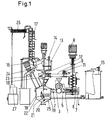
- FIG. 1 shows the scheme of the method according to the invention.
- the pump denotes, on the suction side 2 the material entry 3 and the connection to the circulatory oil 4 has.
- the pressure line 5 On the discharge side, the pressure line 5 is the tangentially into the stirred tank 6 opens.
- a stirrer 7 with a rotating in opposite direction, driven by the electric motor 8.
- Das Agitator 7 has additional upward cleaning arms, the entire Coat the surface of the mixing bowl.
- the stirred tank 6 is connected by a connecting pipe 9 with a hydrocyclone 10 connected.
- a hydrocyclone 10 In the kaus, the mixture of gases in the subsequent apparatuses.
- a further pump In a special design is arranged in this line, a further pump, the controlled by the frequency converter with the pump 1.
- Hydrocyclone 10 has inside a voltage applied to the inner wall venturi 12, which also lowers the remaining pressure and the separation effect elevated.
- hydrocyclone is aetician 13 with a Level control 14 with oil level measurement 15.
- a stirrer is arranged, which is driven by an electric motor and Cleaning arms for the lower part of the containment, the cyclone and the has under the cyclone lying container.
- Der Capacitor 26 is a tube bundle water cooler whose water is in the cooling circuit is recooled.
- Diesel is discharged in the upper part of the column via the upper removal.
- the Quality of the diesel is regulated via the reflux line on the return flow.
- the reflux pipe has a connection to the diesel reservoir of the Power generator 27, which supplies the system with electricity. This consumes about 10% of the diesel generated for the self-powered and also generates the Heat for pre-drying and preheating of the oils by the exhaust gas of the
- All containers are for the purpose of facilitating the heating phase with a provided electrical external heating.
- the separation vessel 18 with the inclined slats 19, for a separation of the non-diesel convertible constituents of the input materials.
- This separation tank 18 is connected to the intake pipe 2. At the bottom of the Abscheide matterser 18 is a temperature measurement 19, which is the Discharge screw 20 sets in operation when the temperature by insulation with the
- the discharge screw 20 has a filter part 21 within the container, the flowing back liquid particles through the filter 22 in the separation vessel 18 leaves and an electrically heated carbonized part 23 outside of the separation vessel 18, which evaporates the remaining oil from the press cake. Is to a temperature increase up to 600 ° C provided. The from the Schwelschnecke 23 escaping oil vapors pass through the steam line 24 in the security container 13.
- a centrifugal pump with 200 kW drive power delivers 5,000 l / h of intake oil via a suction line (2) and about the material entry (3) 600 kg of residues in the form of waste oil and bitumen with a total of 5,600 l / h in the pressure line (5) tangentially into the stirred tank (6) a diameter of 1,400 mm opens.
- the agitator (7) has additional upward cleaning arms, the Coat the entire surface of the stirring container, ie both the lower part of the stirred tank with 1400 mm, as well as the upper part with a diameter of 500 mm.
- the stirred tank (6) is connected by a connecting pipe (9) Diameter of 200 mm connected to a hydrocyclone (10).
- a hydrocyclone (10) Diameter of 200 mm connected to a hydrocyclone (10).
- the hydrocyclone (10) has one Diameter of 1,000 mm and inside a fitting to the inner wall Venturi nozzle (12) with a narrowest cross-section of 100 x 200 mm, which also lowers the remaining overpressure and increases the separation efficiency.
- hydrocyclone Above the hydrocyclone is a safety container (13) with a Diameter of 2,000 mm of a level control (14) with Oil Level Measurement (15). On the safety container (13) is a stirrer arranged, which is driven by electric motor with 10 kW and Cleaning arms for the lower part of the containment, the cyclone and the has under the cyclone lying container.
- the side of the safety container (13) is the product vapor line (16) for the generated diesel vapor to the distillation plant (17) with a column diameter of 500 mm. All containers are for the purpose of facilitating the heating phase with an electric external heating with a total power of 50 kW Mistake.
- This Separation tank (18) is with the intake pipe (2) with 200 mm diameter connected. At the bottom of the separation vessel (18) is a Temperature measurement (19), which sets the discharge screw (20) in operation when the
- the discharge screw (20) with a diameter of 80 mm and a Delivery rate of 10 - 20 kg / h has a filter part (21) inside the container, the liquid portions through the filter screen (22) in the separation vessel (18) flows back and an electrically heated carbonized part (23) outside the Separator (18) with a heating power of 45 kW, the remaining Allow oil to evaporate from the press cake. This is one Temperature increase up to 600 ° C provided. The from the Schwelschnecke (23) escaping oil vapors pass through the steam line (24) in the Safety container (13).
Abstract
Description
Claims (6)
- Verfahren zur Erzeugung von Dieselöl aus kohlenwasserstoffhaltigen Reststoffen in einem Ölkreislauf mit Feststoffabscheidung und Produktdestillation für das Dieselprodukt
dadurch gekennzeichnet, dass der Hauptenergieeintrag und dadurch die Haupterwärmung durch ein oder mehrere Pumpen erfolgt. - Verfahren nach Anspruch 1,
dadurch gekennzeichnet, dass die Strömungsenergie der Pumpe durch ein gegenläufiges Rührwerk gebremst und in Wärme umgewandelt wird. - Verfahren nach Anspruch 1 und 2,
dadurch gekennzeichnet, dass für die katalytische Umwandlung je nach Anwendung die Katalysatoren in Form von volldurchkristallisierten Y-Molekülen mit Natrium für mineralische Kohlenwasserstoffe, wie Bitumen, Öle und Kunststoffe eingesetzt werden und für die biologischen Einsatzstoffe, wie Fette und biologischen Öle Dotierungen mit Kalzium verwendet und für die Umsetzung mit Holz Dotierung mit Magnesium eingesetzt werden, wobei für die hochhalogenhaltigen Stoffe, wie Trafoöl und PVC, die Dotierung mit Kalium eingesetzt wird. - Verfahren nach Anspruch 1,
dadurch gekennzeichnet, dass die restliche Strömungsenergie der Pumpe durch eine regelbare Klappe im oberen Kreislaufrohr und durch die Venturidüse im Zyklon geregelt wird. - Verfahren nach Anspruch 1,
dadurch gekennzeichnet, dass die Anlage eine Temperaturregelung und eine Füllstandsregelung besitzt, die miteinander vernetzt sind, d. h. die Zufuhr- und Energieeintragssysteme sind so gesteuert, dass der Füllstand gewahrt bleibt. - Vorrichtung zur Durchführung des Verfahrens
dadurch gekennzeichnet, dass die Anlage die Komponenten Hochleistungspumpe, gegenläufiger Rührer, Drosselregelungsklappe, Abscheidezyklon im Kreislauf und Abscheidebehälter mit geheizter Austragschnecke und Destillationsanlage an den beiden Ausgängen der Anlage besitzt.
Priority Applications (1)
| Application Number | Priority Date | Filing Date | Title |
|---|---|---|---|
| CY20111101162T CY1112093T1 (el) | 2003-12-02 | 2011-11-25 | Πετρελαιο ντιζελ απο υπολειμματικα υλικα μεσω καταλυτικου αποπολυμερισμου με παροχη ενεργειας απο ενα συστημα αντλιων-αναδευτηρων |
Applications Claiming Priority (2)
| Application Number | Priority Date | Filing Date | Title |
|---|---|---|---|
| DE10356245 | 2003-12-02 | ||
| DE10356245A DE10356245B4 (de) | 2003-12-02 | 2003-12-02 | Verfahren zur Erzeugung von Dieselöl aus kohlenwasserstoffhaltigen Reststoffen sowie eine Vorrichtung zur Durchführung dieses Verfahrens |
Publications (2)
| Publication Number | Publication Date |
|---|---|
| EP1538191A1 true EP1538191A1 (de) | 2005-06-08 |
| EP1538191B1 EP1538191B1 (de) | 2011-08-31 |
Family
ID=34442397
Family Applications (1)
| Application Number | Title | Priority Date | Filing Date |
|---|---|---|---|
| EP04090070A Expired - Lifetime EP1538191B1 (de) | 2003-12-02 | 2004-02-26 | Dieselöl aus Reststoffen durch katalytische Depolymerisation mit dem Energieeintrag in einem Pumpen-Rührwerkssystem |
Country Status (12)
| Country | Link |
|---|---|
| US (1) | US7473348B2 (de) |
| EP (1) | EP1538191B1 (de) |
| JP (1) | JP2005163013A (de) |
| CN (1) | CN1624077A (de) |
| AT (1) | ATE522590T1 (de) |
| BR (1) | BRPI0400912B1 (de) |
| CA (1) | CA2474523A1 (de) |
| CY (1) | CY1112093T1 (de) |
| DE (1) | DE10356245B4 (de) |
| ES (1) | ES2376573T3 (de) |
| MX (1) | MXPA04002431A (de) |
| RU (1) | RU2360946C2 (de) |
Cited By (15)
| Publication number | Priority date | Publication date | Assignee | Title |
|---|---|---|---|---|
| WO2007062811A2 (de) * | 2005-11-29 | 2007-06-07 | Öko Und Bio Beteiligungen Ag | Hochleistungskammermischer für katalytische ölsuspensionen als reaktor und quelle des hauptenergieeintrags für die depolymerisation und polymerisation von kohlenwasserstoffhatigen reststoffen zu mitteldestillat im kreislauf |
| WO2008061484A1 (de) * | 2006-11-20 | 2008-05-29 | Christian Koch | Hochleistungskammermischer für katalytische ölsuspensionen |
| DE102006060224A1 (de) | 2006-12-20 | 2008-07-03 | Buchert, Jürgen | Katalytische Erzeugungsanlage für Dieselöl |
| WO2008102307A1 (en) * | 2007-02-21 | 2008-08-28 | Vuzeta Brevetti S.R.L. | Apparatus for producing synthetic fuel |
| WO2009066251A1 (en) * | 2007-11-22 | 2009-05-28 | Vuzeta Brevetti S.R.L. | Method and apparatus for treating waste materials |
| DE102008003209B3 (de) * | 2008-01-05 | 2009-06-04 | Relux Umwelt Gmbh | Verfahren und Vorrichtung zur Erzeugung von Mitteldestillat aus kohlenwasserstoffhaltigen Energieträgern |
| WO2010063248A2 (de) * | 2008-12-05 | 2010-06-10 | Christian Koch | Ölreaktorvakuumpumpe mit hydraulischer dichtung für katalytische verölungsreaktionen aus vorab aufbereiteten, breiartigen reststoffen und ein verfahren dazu |
| WO2012016633A2 (de) | 2010-07-26 | 2012-02-09 | Wieser-Linhart Emil A J | Anlage und verfahren zur erzeugung von treibstoffen aus biomasse / kunststoff - gemischen |
| DE102012010763A1 (de) | 2012-03-26 | 2013-09-26 | Axel Trautmann | Vorrichtung und Verfahren zur katalytischen Depolymerisation von Kohlenstoff enthaltendem Material |
| WO2014106650A2 (de) | 2013-01-03 | 2014-07-10 | EZER, Argun | Verfahren und vorrichtungen zur verölung von kohlenwasserstoffhaltigem eingangsmaterial |
| ES2503442A1 (es) * | 2013-04-03 | 2014-10-06 | Jordi HUGUET FARRE | Procedimiento de valorización integral de residuos para la obtención de combustible diesel sintético |
| WO2015007344A1 (de) * | 2013-07-19 | 2015-01-22 | Catalytec | Verfahren und vorrichtung zur gewinnung einer kohlenwasserstoffe-haltigen zusammensetzung aus reststoffen |
| WO2015007343A1 (de) * | 2013-07-19 | 2015-01-22 | Catalytec | Verfahren und vorrichtung zur gewinnung einer kohlenwasserstoffe-haltigen zusammensetzung aus reststoffen |
| WO2018189267A1 (de) * | 2017-04-11 | 2018-10-18 | Innoil Ag | Reaktionsbehälter |
| EP3599342A1 (de) | 2018-07-27 | 2020-01-29 | Alphakat Holding International Ltd. | Plattform zur ölförderung |
Families Citing this family (31)
| Publication number | Priority date | Publication date | Assignee | Title |
|---|---|---|---|---|
| US7344622B2 (en) * | 2003-04-08 | 2008-03-18 | Grispin Charles W | Pyrolytic process and apparatus for producing enhanced amounts of aromatic compounds |
| WO2006043924A1 (en) * | 2004-10-13 | 2006-04-27 | Charlie Holding Intellectual Property, Inc. | Pyrolytic process and apparatus for producing enhanced amounts of aromatic compounds |
| EP1745840A1 (de) * | 2005-07-22 | 2007-01-24 | Services Petroliers Schlumberger | Vorrichtung und Verfahren zum Mischen eines flüssigen und eines fliessfähigen pulverförmigen Materials zur Herstellung einer Suspension |
| US20110235460A1 (en) * | 2005-07-22 | 2011-09-29 | Schlumberger Technology Corporation | Method and apparatus to optimize the mixing process |
| DE102006061217B3 (de) * | 2006-12-22 | 2008-06-05 | Buchert, Jürgen | Verfahren zur thermischen Aufbereitung von Klärschlamm und Einrichtung zur Durchführung des Verfahrens |
| DE102007011763B3 (de) * | 2007-03-10 | 2008-11-20 | Buchert, Jürgen | Verfahren zur katalytischen Aufbereitung von Klärschlamm und Einrichtung zur Durchführung des Verfahrens |
| US7491856B2 (en) | 2007-06-27 | 2009-02-17 | H R D Corporation | Method of making alkylene glycols |
| US8304584B2 (en) | 2007-06-27 | 2012-11-06 | H R D Corporation | Method of making alkylene glycols |
| US7696391B2 (en) * | 2007-06-27 | 2010-04-13 | H R D Corporation | System and process for production of nitrobenzene |
| ITBO20080072A1 (it) * | 2008-02-01 | 2009-08-02 | Vuzeta Brevetti S R L | Apparato per il trattamento di materiali di rifiuto |
| DE102008013241B4 (de) * | 2008-03-08 | 2010-05-20 | Buchert, Jürgen | Verfahren zur thermischen Aufbereitung von Biomasse und Einrichtung zur Durchführung des Verfahrens |
| US20090267349A1 (en) | 2008-04-23 | 2009-10-29 | Spitzauer Michael P | Production Processes, Systems, Methods, and Apparatuses |
| DE102009033216A1 (de) | 2009-07-15 | 2011-01-27 | Brümmer, Heinz | Vorrichtung und Verfahren zur Herstellung von Leichtölen aus Biomasse und kohlenwasserstoffhaltigen Stoffen mittels Verpressen der Reaktionsmasse zusammen mit einem zeolithischen Katalysator als Reaktionsbeschleuniger zu Pellets und anschließender Molekülverkürzung der Reaktionsmasse durch von Mikrowellenstrahlung initiiertem Plasma in einem Flachbettreaktor |
| ITVR20110169A1 (it) | 2011-08-10 | 2013-02-11 | Irle S R L | Impianto e processo per la conversione catalitica di rifiuti in fluidi combustibili |
| WO2013057735A1 (en) | 2011-10-21 | 2013-04-25 | Turlapati Raghavendra Rao | "process and plant for conversion of segregated or unsegregated carbonaceous homogeneous and non- homogeneous waste feed into hydrocarbon fuels" |
| PL398335A1 (pl) | 2012-03-07 | 2013-09-16 | Idea Spólka Z Ograniczona Odpowiedzialnoscia | Sposób wytwarzania uszlachetnionego paliwa do silników wysokopreznych oraz uszlachetnione paliwo do silników wysokopreznych |
| DE102012204657A1 (de) | 2012-03-22 | 2013-09-26 | Wilfried Schraufstetter | Modular aufgebauten Reaktor zur Verflüssigung von Abfallstoffen mit horizontal geteilter Heizmittelführung |
| PL399654A1 (pl) | 2012-06-25 | 2014-01-07 | Green Power Spólka Z Ograniczona Odpowiedzialnoscia Spólka W Organizacji | Sposób wytwarzania uszlachetnionego biokomponentu do biopaliw oraz uszlachetniony biokomponent do biopaliw |
| PL400489A1 (pl) | 2012-08-23 | 2014-03-03 | Glob Investment Spólka Z Ograniczona Odpowiedzialnoscia | Sposób wytwarzania paliwa oraz paliwo |
| PL400488A1 (pl) | 2012-08-23 | 2014-03-03 | Glob Investment Spólka Z Ograniczona Odpowiedzialnoscia | Sposób wytwarzania paliwa oraz paliwo |
| ITVR20150065A1 (it) | 2015-04-22 | 2016-10-22 | Convecom S R L | Procedimento di decomposizione termochimica di rifiuti |
| FR3061492B1 (fr) * | 2017-01-03 | 2019-05-24 | D.M.S | Procede de production de carburant par craquage catalytique d'un materiau solide hydrocarbone et dispositif pour sa mise en œuvre |
| US10723956B2 (en) | 2017-07-21 | 2020-07-28 | 1888711 Alberta Inc. | Enhanced distillate oil recovery from thermal processing and catalytic cracking of biomass slurry |
| WO2019038276A1 (de) | 2017-08-23 | 2019-02-28 | Karl Morgenbesser | Vorrichtung und verfahren zur katalytischen und/order drucklosen verölung |
| CA3086818A1 (en) | 2017-12-13 | 2019-06-20 | Karl Ip Holdings Inc. | Low-pressure catalytic conversion of used motor oil to diesel fuel |
| DE102019001696A1 (de) | 2019-03-11 | 2020-09-17 | Olaf Heimbürge | Anlage und Verfahren zur katalytischen Herstellung von Dieselölen aus organischen Materialien |
| DE102019001702A1 (de) | 2019-03-11 | 2020-09-17 | Olaf Heimbürge | Anlage und Verfahren zur katalytischen Herstellung von Dieselölen aus organischen Materialien |
| DE102019001697A1 (de) | 2019-03-11 | 2020-09-17 | Olaf Heimbürge | Anlage und Verfahren zur katalytischen Herstellung von Dieselölen aus organischen Materialien |
| US10953381B1 (en) | 2020-03-24 | 2021-03-23 | Tge Ip Llc | Chemical reactor with high speed rotary mixing, for catalytic thermal conversion of organic materials into diesel and other liquid fuels, and applications thereof |
| DE102020004964A1 (de) | 2020-08-14 | 2022-02-17 | Timon Kasielke | Anlage und Verfahren zur katalytischen Herstellung von Dieselölen aus organischen Materialien |
| US20240047015A1 (en) | 2021-01-20 | 2024-02-08 | Jems, Energetska Družba, D.O.O. | Systems and methods for plant process optimisation |
Citations (4)
| Publication number | Priority date | Publication date | Assignee | Title |
|---|---|---|---|---|
| US2764147A (en) * | 1951-02-23 | 1956-09-25 | Northrop Aircraft Inc | Frictional heater for hydraulic system |
| US4781151A (en) * | 1986-11-24 | 1988-11-01 | Wolpert Jr George H | Flameless heat source |
| DE4435238A1 (de) * | 1993-04-03 | 1996-04-11 | Veba Oel Ag | Verfahren zur Gewinnung von Chemierohstoffen und Kraftstoffkomponenten aus Alt- oder Abfallkunststoffen |
| DE10049377A1 (de) * | 2000-10-05 | 2002-04-18 | Evk Dr Oberlaender Gmbh & Co K | Katalytische Erzeugung von Dieselöl und Benzinen aus kohlenwasserstoffhaltigen Abfällen und Ölen |
Family Cites Families (10)
| Publication number | Priority date | Publication date | Assignee | Title |
|---|---|---|---|---|
| US2105191A (en) * | 1938-01-11 | Method for cracking petroleum oils | ||
| US1754136A (en) * | 1924-07-08 | 1930-04-08 | Woidich Francis Sales | Process and apparatus for converting heavy hydrocarbon oils into lighter products |
| US1904586A (en) * | 1926-12-22 | 1933-04-18 | Ig Farbenindustrie Ag | Conversion of carbonaceous solids into valuable liquid products |
| BE523969A (de) * | 1952-11-08 | |||
| US4300009A (en) * | 1978-12-28 | 1981-11-10 | Mobil Oil Corporation | Conversion of biological material to liquid fuels |
| US5073251A (en) * | 1982-10-19 | 1991-12-17 | Daniels Ludlow S | Method of an apparatus for recovering oil from solid hydrocarbonaceous material |
| FR2560204A1 (fr) * | 1984-02-24 | 1985-08-30 | Elf Aquitaine | Procede et installation de distillation de petrole par separations progressives |
| US4663025A (en) * | 1986-08-14 | 1987-05-05 | Phillips Petroleum Company | Catalytic cracking processes |
| US5244565A (en) * | 1990-08-17 | 1993-09-14 | Uop | Integrated process for the production of distillate hydrocarbon |
| RU2184136C1 (ru) * | 2001-01-17 | 2002-06-27 | Открытое акционерное общество "Эттис" | Способ получения светлых нефтепродуктов и установка для его осуществления |
-
2003
- 2003-12-02 DE DE10356245A patent/DE10356245B4/de not_active Expired - Fee Related
-
2004
- 2004-02-26 AT AT04090070T patent/ATE522590T1/de active
- 2004-02-26 EP EP04090070A patent/EP1538191B1/de not_active Expired - Lifetime
- 2004-02-26 ES ES04090070T patent/ES2376573T3/es not_active Expired - Lifetime
- 2004-03-15 MX MXPA04002431A patent/MXPA04002431A/es active IP Right Grant
- 2004-03-23 CN CNA2004100302703A patent/CN1624077A/zh active Pending
- 2004-03-30 RU RU2004109567/04A patent/RU2360946C2/ru active IP Right Revival
- 2004-03-31 BR BRPI0400912-6B1A patent/BRPI0400912B1/pt not_active IP Right Cessation
- 2004-07-15 CA CA002474523A patent/CA2474523A1/en not_active Abandoned
- 2004-07-15 US US10/891,971 patent/US7473348B2/en active Active - Reinstated
- 2004-10-08 JP JP2004295764A patent/JP2005163013A/ja active Pending
-
2011
- 2011-11-25 CY CY20111101162T patent/CY1112093T1/el unknown
Patent Citations (5)
| Publication number | Priority date | Publication date | Assignee | Title |
|---|---|---|---|---|
| US2764147A (en) * | 1951-02-23 | 1956-09-25 | Northrop Aircraft Inc | Frictional heater for hydraulic system |
| US4781151A (en) * | 1986-11-24 | 1988-11-01 | Wolpert Jr George H | Flameless heat source |
| DE4435238A1 (de) * | 1993-04-03 | 1996-04-11 | Veba Oel Ag | Verfahren zur Gewinnung von Chemierohstoffen und Kraftstoffkomponenten aus Alt- oder Abfallkunststoffen |
| US5849964A (en) * | 1993-04-03 | 1998-12-15 | Veba Oel Aktiengesellschaft | Process for the processing of salvaged or waste plastic materials |
| DE10049377A1 (de) * | 2000-10-05 | 2002-04-18 | Evk Dr Oberlaender Gmbh & Co K | Katalytische Erzeugung von Dieselöl und Benzinen aus kohlenwasserstoffhaltigen Abfällen und Ölen |
Cited By (22)
| Publication number | Priority date | Publication date | Assignee | Title |
|---|---|---|---|---|
| EP1798274A1 (de) * | 2005-11-29 | 2007-06-20 | Christian Koch | Hochleistungskammermischer für katalytische Ölsuspensionen als Reaktor und Quelle des Hauptenergieeintrags für die Depolymerisation und Polymerisation von kohlenwasserstoffhaltigen Reststoffen zu Mitteldestillat im Kreislauf |
| WO2007062811A3 (de) * | 2005-11-29 | 2007-07-12 | Oeko Und Bio Beteiligungen Ag | Hochleistungskammermischer für katalytische ölsuspensionen als reaktor und quelle des hauptenergieeintrags für die depolymerisation und polymerisation von kohlenwasserstoffhatigen reststoffen zu mitteldestillat im kreislauf |
| WO2007062811A2 (de) * | 2005-11-29 | 2007-06-07 | Öko Und Bio Beteiligungen Ag | Hochleistungskammermischer für katalytische ölsuspensionen als reaktor und quelle des hauptenergieeintrags für die depolymerisation und polymerisation von kohlenwasserstoffhatigen reststoffen zu mitteldestillat im kreislauf |
| WO2008061484A1 (de) * | 2006-11-20 | 2008-05-29 | Christian Koch | Hochleistungskammermischer für katalytische ölsuspensionen |
| DE102006060224A1 (de) | 2006-12-20 | 2008-07-03 | Buchert, Jürgen | Katalytische Erzeugungsanlage für Dieselöl |
| WO2008102307A1 (en) * | 2007-02-21 | 2008-08-28 | Vuzeta Brevetti S.R.L. | Apparatus for producing synthetic fuel |
| WO2009066251A1 (en) * | 2007-11-22 | 2009-05-28 | Vuzeta Brevetti S.R.L. | Method and apparatus for treating waste materials |
| DE102008003209B3 (de) * | 2008-01-05 | 2009-06-04 | Relux Umwelt Gmbh | Verfahren und Vorrichtung zur Erzeugung von Mitteldestillat aus kohlenwasserstoffhaltigen Energieträgern |
| WO2010063248A2 (de) * | 2008-12-05 | 2010-06-10 | Christian Koch | Ölreaktorvakuumpumpe mit hydraulischer dichtung für katalytische verölungsreaktionen aus vorab aufbereiteten, breiartigen reststoffen und ein verfahren dazu |
| RU2523535C2 (ru) * | 2009-02-20 | 2014-07-20 | Альфапат Истэблишмент | Вакуумный насос-маслопроизводящий реактор с гидравлическим уплотнителем для каталитических реакций риформинга из предварительно обработанных пульпообразных отходов и способ к нему |
| WO2010063248A3 (de) * | 2009-02-20 | 2010-11-25 | Christian Koch | Ölreaktorvakuumpumpe mit hydraulischer dichtung für katalytische verölungsreaktionen aus vorab aufbereiteten, breiartigen reststoffen und ein verfahren dazu |
| WO2012016633A2 (de) | 2010-07-26 | 2012-02-09 | Wieser-Linhart Emil A J | Anlage und verfahren zur erzeugung von treibstoffen aus biomasse / kunststoff - gemischen |
| WO2013143685A1 (de) | 2012-03-26 | 2013-10-03 | Axel Trautmann | Vorrichtung und verfahren zur katalytischen depolymerisation von kohlenwasserstoff enthaltendem material |
| DE102012010763A1 (de) | 2012-03-26 | 2013-09-26 | Axel Trautmann | Vorrichtung und Verfahren zur katalytischen Depolymerisation von Kohlenstoff enthaltendem Material |
| WO2014106650A2 (de) | 2013-01-03 | 2014-07-10 | EZER, Argun | Verfahren und vorrichtungen zur verölung von kohlenwasserstoffhaltigem eingangsmaterial |
| ES2503442A1 (es) * | 2013-04-03 | 2014-10-06 | Jordi HUGUET FARRE | Procedimiento de valorización integral de residuos para la obtención de combustible diesel sintético |
| WO2015007344A1 (de) * | 2013-07-19 | 2015-01-22 | Catalytec | Verfahren und vorrichtung zur gewinnung einer kohlenwasserstoffe-haltigen zusammensetzung aus reststoffen |
| WO2015007343A1 (de) * | 2013-07-19 | 2015-01-22 | Catalytec | Verfahren und vorrichtung zur gewinnung einer kohlenwasserstoffe-haltigen zusammensetzung aus reststoffen |
| WO2018189267A1 (de) * | 2017-04-11 | 2018-10-18 | Innoil Ag | Reaktionsbehälter |
| US11071960B2 (en) | 2017-04-11 | 2021-07-27 | Innoil Ag | Reaction container |
| EP3599342A1 (de) | 2018-07-27 | 2020-01-29 | Alphakat Holding International Ltd. | Plattform zur ölförderung |
| WO2020020481A1 (en) | 2018-07-27 | 2020-01-30 | Alphakat Holding International Ltd. Cypern | Platform for oil production |
Also Published As
| Publication number | Publication date |
|---|---|
| CY1112093T1 (el) | 2015-11-04 |
| US7473348B2 (en) | 2009-01-06 |
| JP2005163013A (ja) | 2005-06-23 |
| RU2360946C2 (ru) | 2009-07-10 |
| BRPI0400912B1 (pt) | 2015-01-27 |
| CN1624077A (zh) | 2005-06-08 |
| DE10356245A1 (de) | 2005-07-21 |
| CA2474523A1 (en) | 2005-06-02 |
| DE10356245B4 (de) | 2007-01-25 |
| US20050115871A1 (en) | 2005-06-02 |
| RU2004109567A (ru) | 2005-10-20 |
| BRPI0400912A (pt) | 2005-08-30 |
| ATE522590T1 (de) | 2011-09-15 |
| MXPA04002431A (es) | 2005-09-08 |
| EP1538191B1 (de) | 2011-08-31 |
| ES2376573T3 (es) | 2012-03-15 |
Similar Documents
| Publication | Publication Date | Title |
|---|---|---|
| DE10356245B4 (de) | Verfahren zur Erzeugung von Dieselöl aus kohlenwasserstoffhaltigen Reststoffen sowie eine Vorrichtung zur Durchführung dieses Verfahrens | |
| DE102005056735B3 (de) | Hochleistungskammermischer für katalytische Ölsuspensionen als Reaktor für die Depolymerisation und Polymerisation von kohlenwasserstoffhaltigen Reststoffen zu Mitteldestillat im Kreislauf | |
| DE102005010151B3 (de) | Verfahren zum katalytischen Depolymerisieren von kohlenwasserstoffhaltigen Rückständen sowie Vorrichtung zum Durchführen dieses Verfahrens | |
| DE69920489T2 (de) | Integriertes lösungsmittelentasphaltierungs- und vergasungsverfahren | |
| EP2718403B1 (de) | Verfahren zur herstellung von flüssigem kohlenwasserstoff | |
| EP2718404B1 (de) | Verfahren zur herstellung flüssiger kohlenwasserstoffe | |
| DE102008013241B4 (de) | Verfahren zur thermischen Aufbereitung von Biomasse und Einrichtung zur Durchführung des Verfahrens | |
| DE102006061217B3 (de) | Verfahren zur thermischen Aufbereitung von Klärschlamm und Einrichtung zur Durchführung des Verfahrens | |
| DE19631201C2 (de) | Verfahren und Reaktor zur Umwandlung von Biomasse in flüssige, feste oder gasförmige Brennstoffe und Chemierohstoffe | |
| JP2014518906A (ja) | 二次的資源をエネルギー効率よく処理するための方法及び装置 | |
| EP3177698B1 (de) | Vorrichtung und verfahren zur katalytisch drucklosen verölung | |
| US20120217149A1 (en) | Decomposition of waste plastics | |
| DE102008003209B3 (de) | Verfahren und Vorrichtung zur Erzeugung von Mitteldestillat aus kohlenwasserstoffhaltigen Energieträgern | |
| WO2004092305A1 (de) | Verfahren und vorrichtung zur katalytischen behandlung von reststoffen in kontinuierlich gereinigten und beheizten rohrbündelreaktoren | |
| WO2018228619A1 (de) | Verfahren und vorrichtung zur katalytischen drucklosen verölung von kohlenwasserstoffhaltigen substanzen | |
| WO2014106650A2 (de) | Verfahren und vorrichtungen zur verölung von kohlenwasserstoffhaltigem eingangsmaterial | |
| DE102010060675B4 (de) | Verfahren und Anlage zur Gewinnung von Dieselöl aus kohlenwasserstoffhaltigen Roh- und Reststoffen | |
| WO2008034596A1 (de) | Anlage und verfahren zur erzeugung von treibstoffen aus biogenen rohstoffen | |
| DE102008047563A1 (de) | Verfahren und Vorrichtung zur Aufbereitung von kunststoffhaltigen Stoffen | |
| DE102007051373B4 (de) | Verfahren und Vorrichtung zur Gewinnung von Diesel oder Heizöl aus kohlenwasserstoffhaltigen Rückständen | |
| DE102012022710B4 (de) | Verfahren und Vorrichtung zur dezentralen mobilen Aufarbeitung von Erdöl, Kohle, grünen Abfällen und aufbereitetem Müll zu Mitteldestillaten und schwefelarmer, wasserfreier Glühkohle mit Mischungsturbinen | |
| EP3036309A1 (de) | Zwangsgasrückführung in raffinationsprozessen einer späteren phase und reaktoren | |
| US7736469B2 (en) | Production of hydrocarbon fuel | |
| DE102008029927B4 (de) | Flash-Pyrolyse von organischen Stoffen mit ionischer Flüssigkeit als Wärmeträger zur Herstellung von öligen bzw. gasförmigen Zwischenprodukten | |
| CN113999690B (zh) | 一种煤焦油流化床热解处理的装置及方法 |
Legal Events
| Date | Code | Title | Description |
|---|---|---|---|
| PUAI | Public reference made under article 153(3) epc to a published international application that has entered the european phase |
Free format text: ORIGINAL CODE: 0009012 |
|
| AK | Designated contracting states |
Kind code of ref document: A1 Designated state(s): AT BE BG CH CY CZ DE DK EE ES FI FR GB GR HU IE IT LI LU MC NL PT RO SE SI SK TR |
|
| AX | Request for extension of the european patent |
Extension state: AL HR LT LV MK |
|
| 17P | Request for examination filed |
Effective date: 20050622 |
|
| AKX | Designation fees paid |
Designated state(s): AT BE BG CH CY CZ DE DK EE ES FI FR GB GR HU IE IT LI LU MC NL PT RO SE SI SK TR |
|
| AXX | Extension fees paid |
Extension state: LT Payment date: 20050622 Extension state: AL Payment date: 20050622 Extension state: MK Payment date: 20050622 Extension state: LV Payment date: 20050622 |
|
| GRAP | Despatch of communication of intention to grant a patent |
Free format text: ORIGINAL CODE: EPIDOSNIGR1 |
|
| GRAS | Grant fee paid |
Free format text: ORIGINAL CODE: EPIDOSNIGR3 |
|
| GRAA | (expected) grant |
Free format text: ORIGINAL CODE: 0009210 |
|
| AK | Designated contracting states |
Kind code of ref document: B1 Designated state(s): AT BE BG CH CY CZ DE DK EE ES FI FR GB GR HU IE IT LI LU MC NL PT RO SE SI SK TR |
|
| AX | Request for extension of the european patent |
Extension state: AL LT LV MK |
|
| REG | Reference to a national code |
Ref country code: CH Ref legal event code: EP Ref country code: GB Ref legal event code: FG4D Free format text: NOT ENGLISH |
|
| REG | Reference to a national code |
Ref country code: IE Ref legal event code: FG4D Free format text: LANGUAGE OF EP DOCUMENT: GERMAN |
|
| REG | Reference to a national code |
Ref country code: DE Ref legal event code: R096 Ref document number: 502004012835 Country of ref document: DE Effective date: 20111027 |
|
| REG | Reference to a national code |
Ref country code: SE Ref legal event code: TRGR |
|
| REG | Reference to a national code |
Ref country code: NL Ref legal event code: T3 |
|
| LTIE | Lt: invalidation of european patent or patent extension |
Effective date: 20110831 |
|
| PG25 | Lapsed in a contracting state [announced via postgrant information from national office to epo] |
Ref country code: SI Free format text: LAPSE BECAUSE OF FAILURE TO SUBMIT A TRANSLATION OF THE DESCRIPTION OR TO PAY THE FEE WITHIN THE PRESCRIBED TIME-LIMIT Effective date: 20110831 |
|
| REG | Reference to a national code |
Ref country code: GR Ref legal event code: EP Ref document number: 20110402808 Country of ref document: GR Effective date: 20120117 |
|
| REG | Reference to a national code |
Ref country code: ES Ref legal event code: FG2A Ref document number: 2376573 Country of ref document: ES Kind code of ref document: T3 Effective date: 20120315 |
|
| REG | Reference to a national code |
Ref country code: IE Ref legal event code: FD4D |
|
| PG25 | Lapsed in a contracting state [announced via postgrant information from national office to epo] |
Ref country code: IE Free format text: LAPSE BECAUSE OF FAILURE TO SUBMIT A TRANSLATION OF THE DESCRIPTION OR TO PAY THE FEE WITHIN THE PRESCRIBED TIME-LIMIT Effective date: 20110831 Ref country code: SK Free format text: LAPSE BECAUSE OF FAILURE TO SUBMIT A TRANSLATION OF THE DESCRIPTION OR TO PAY THE FEE WITHIN THE PRESCRIBED TIME-LIMIT Effective date: 20110831 |
|
| PG25 | Lapsed in a contracting state [announced via postgrant information from national office to epo] |
Ref country code: PT Free format text: LAPSE BECAUSE OF FAILURE TO SUBMIT A TRANSLATION OF THE DESCRIPTION OR TO PAY THE FEE WITHIN THE PRESCRIBED TIME-LIMIT Effective date: 20120102 Ref country code: EE Free format text: LAPSE BECAUSE OF FAILURE TO SUBMIT A TRANSLATION OF THE DESCRIPTION OR TO PAY THE FEE WITHIN THE PRESCRIBED TIME-LIMIT Effective date: 20110831 Ref country code: RO Free format text: LAPSE BECAUSE OF FAILURE TO SUBMIT A TRANSLATION OF THE DESCRIPTION OR TO PAY THE FEE WITHIN THE PRESCRIBED TIME-LIMIT Effective date: 20110831 |
|
| PG25 | Lapsed in a contracting state [announced via postgrant information from national office to epo] |
Ref country code: DK Free format text: LAPSE BECAUSE OF FAILURE TO SUBMIT A TRANSLATION OF THE DESCRIPTION OR TO PAY THE FEE WITHIN THE PRESCRIBED TIME-LIMIT Effective date: 20110831 |
|
| PLBE | No opposition filed within time limit |
Free format text: ORIGINAL CODE: 0009261 |
|
| STAA | Information on the status of an ep patent application or granted ep patent |
Free format text: STATUS: NO OPPOSITION FILED WITHIN TIME LIMIT |
|
| REG | Reference to a national code |
Ref country code: HU Ref legal event code: AG4A Ref document number: E013302 Country of ref document: HU |
|
| 26N | No opposition filed |
Effective date: 20120601 |
|
| REG | Reference to a national code |
Ref country code: DE Ref legal event code: R097 Ref document number: 502004012835 Country of ref document: DE Effective date: 20120601 |
|
| PG25 | Lapsed in a contracting state [announced via postgrant information from national office to epo] |
Ref country code: MC Free format text: LAPSE BECAUSE OF NON-PAYMENT OF DUE FEES Effective date: 20120229 |
|
| PG25 | Lapsed in a contracting state [announced via postgrant information from national office to epo] |
Ref country code: CY Free format text: LAPSE BECAUSE OF NON-PAYMENT OF DUE FEES Effective date: 20120226 |
|
| PG25 | Lapsed in a contracting state [announced via postgrant information from national office to epo] |
Ref country code: HU Free format text: LAPSE BECAUSE OF NON-PAYMENT OF DUE FEES Effective date: 20120227 |
|
| PG25 | Lapsed in a contracting state [announced via postgrant information from national office to epo] |
Ref country code: BG Free format text: LAPSE BECAUSE OF FAILURE TO SUBMIT A TRANSLATION OF THE DESCRIPTION OR TO PAY THE FEE WITHIN THE PRESCRIBED TIME-LIMIT Effective date: 20111130 |
|
| PG25 | Lapsed in a contracting state [announced via postgrant information from national office to epo] |
Ref country code: LU Free format text: LAPSE BECAUSE OF NON-PAYMENT OF DUE FEES Effective date: 20120226 |
|
| PGFP | Annual fee paid to national office [announced via postgrant information from national office to epo] |
Ref country code: CH Payment date: 20150226 Year of fee payment: 12 Ref country code: DE Payment date: 20150210 Year of fee payment: 12 |
|
| PGFP | Annual fee paid to national office [announced via postgrant information from national office to epo] |
Ref country code: SE Payment date: 20150226 Year of fee payment: 12 |
|
| REG | Reference to a national code |
Ref country code: FR Ref legal event code: PLFP Year of fee payment: 12 |
|
| REG | Reference to a national code |
Ref country code: FR Ref legal event code: PLFP Year of fee payment: 13 |
|
| PGFP | Annual fee paid to national office [announced via postgrant information from national office to epo] |
Ref country code: CZ Payment date: 20160223 Year of fee payment: 13 Ref country code: ES Payment date: 20160322 Year of fee payment: 13 |
|
| PGFP | Annual fee paid to national office [announced via postgrant information from national office to epo] |
Ref country code: GR Payment date: 20160226 Year of fee payment: 13 Ref country code: NL Payment date: 20160226 Year of fee payment: 13 Ref country code: GB Payment date: 20160322 Year of fee payment: 13 Ref country code: BE Payment date: 20160322 Year of fee payment: 13 Ref country code: AT Payment date: 20160226 Year of fee payment: 13 Ref country code: FI Payment date: 20160318 Year of fee payment: 13 Ref country code: FR Payment date: 20160322 Year of fee payment: 13 |
|
| PGFP | Annual fee paid to national office [announced via postgrant information from national office to epo] |
Ref country code: IT Payment date: 20160318 Year of fee payment: 13 |
|
| REG | Reference to a national code |
Ref country code: DE Ref legal event code: R119 Ref document number: 502004012835 Country of ref document: DE |
|
| REG | Reference to a national code |
Ref country code: CH Ref legal event code: PL |
|
| REG | Reference to a national code |
Ref country code: SE Ref legal event code: EUG |
|
| PG25 | Lapsed in a contracting state [announced via postgrant information from national office to epo] |
Ref country code: CH Free format text: LAPSE BECAUSE OF NON-PAYMENT OF DUE FEES Effective date: 20160229 Ref country code: LI Free format text: LAPSE BECAUSE OF NON-PAYMENT OF DUE FEES Effective date: 20160229 |
|
| PG25 | Lapsed in a contracting state [announced via postgrant information from national office to epo] |
Ref country code: SE Free format text: LAPSE BECAUSE OF NON-PAYMENT OF DUE FEES Effective date: 20160227 |
|
| PG25 | Lapsed in a contracting state [announced via postgrant information from national office to epo] |
Ref country code: DE Free format text: LAPSE BECAUSE OF NON-PAYMENT OF DUE FEES Effective date: 20160901 |
|
| PG25 | Lapsed in a contracting state [announced via postgrant information from national office to epo] |
Ref country code: BE Free format text: LAPSE BECAUSE OF NON-PAYMENT OF DUE FEES Effective date: 20170228 |
|
| REG | Reference to a national code |
Ref country code: NL Ref legal event code: MM Effective date: 20170301 |
|
| REG | Reference to a national code |
Ref country code: AT Ref legal event code: MM01 Ref document number: 522590 Country of ref document: AT Kind code of ref document: T Effective date: 20170226 |
|
| GBPC | Gb: european patent ceased through non-payment of renewal fee |
Effective date: 20170226 |
|
| PG25 | Lapsed in a contracting state [announced via postgrant information from national office to epo] |
Ref country code: CZ Free format text: LAPSE BECAUSE OF NON-PAYMENT OF DUE FEES Effective date: 20170226 Ref country code: AT Free format text: LAPSE BECAUSE OF NON-PAYMENT OF DUE FEES Effective date: 20170226 Ref country code: FI Free format text: LAPSE BECAUSE OF NON-PAYMENT OF DUE FEES Effective date: 20170226 Ref country code: GR Free format text: LAPSE BECAUSE OF NON-PAYMENT OF DUE FEES Effective date: 20170906 |
|
| PG25 | Lapsed in a contracting state [announced via postgrant information from national office to epo] |
Ref country code: NL Free format text: LAPSE BECAUSE OF NON-PAYMENT OF DUE FEES Effective date: 20170301 |
|
| REG | Reference to a national code |
Ref country code: FR Ref legal event code: ST Effective date: 20171031 |
|
| PG25 | Lapsed in a contracting state [announced via postgrant information from national office to epo] |
Ref country code: FR Free format text: LAPSE BECAUSE OF NON-PAYMENT OF DUE FEES Effective date: 20170228 |
|
| REG | Reference to a national code |
Ref country code: BE Ref legal event code: MM Effective date: 20170228 |
|
| PG25 | Lapsed in a contracting state [announced via postgrant information from national office to epo] |
Ref country code: IT Free format text: LAPSE BECAUSE OF NON-PAYMENT OF DUE FEES Effective date: 20170226 Ref country code: GB Free format text: LAPSE BECAUSE OF NON-PAYMENT OF DUE FEES Effective date: 20170226 |
|
| REG | Reference to a national code |
Ref country code: ES Ref legal event code: FD2A Effective date: 20180705 |
|
| PG25 | Lapsed in a contracting state [announced via postgrant information from national office to epo] |
Ref country code: ES Free format text: LAPSE BECAUSE OF NON-PAYMENT OF DUE FEES Effective date: 20170227 |
|
| PGFP | Annual fee paid to national office [announced via postgrant information from national office to epo] |
Ref country code: TR Payment date: 20230201 Year of fee payment: 20 |