EP1538191B1 - Dieselöl aus Reststoffen durch katalytische Depolymerisation mit dem Energieeintrag in einem Pumpen-Rührwerkssystem - Google Patents
Dieselöl aus Reststoffen durch katalytische Depolymerisation mit dem Energieeintrag in einem Pumpen-Rührwerkssystem Download PDFInfo
- Publication number
- EP1538191B1 EP1538191B1 EP04090070A EP04090070A EP1538191B1 EP 1538191 B1 EP1538191 B1 EP 1538191B1 EP 04090070 A EP04090070 A EP 04090070A EP 04090070 A EP04090070 A EP 04090070A EP 1538191 B1 EP1538191 B1 EP 1538191B1
- Authority
- EP
- European Patent Office
- Prior art keywords
- oil
- feed oil
- catalyst
- doped
- pump
- Prior art date
- Legal status (The legal status is an assumption and is not a legal conclusion. Google has not performed a legal analysis and makes no representation as to the accuracy of the status listed.)
- Expired - Lifetime
Links
- 239000002283 diesel fuel Substances 0.000 title claims abstract description 9
- 239000000463 material Substances 0.000 title claims description 13
- 230000003197 catalytic effect Effects 0.000 title claims description 4
- 238000010438 heat treatment Methods 0.000 claims abstract description 15
- 238000004821 distillation Methods 0.000 claims abstract description 5
- 238000004519 manufacturing process Methods 0.000 claims abstract description 3
- 239000003921 oil Substances 0.000 claims description 18
- 238000000926 separation method Methods 0.000 claims description 17
- 238000000034 method Methods 0.000 claims description 15
- 239000003054 catalyst Substances 0.000 claims description 11
- OYPRJOBELJOOCE-UHFFFAOYSA-N Calcium Chemical compound [Ca] OYPRJOBELJOOCE-UHFFFAOYSA-N 0.000 claims description 3
- FYYHWMGAXLPEAU-UHFFFAOYSA-N Magnesium Chemical compound [Mg] FYYHWMGAXLPEAU-UHFFFAOYSA-N 0.000 claims description 3
- ZLMJMSJWJFRBEC-UHFFFAOYSA-N Potassium Chemical compound [K] ZLMJMSJWJFRBEC-UHFFFAOYSA-N 0.000 claims description 3
- 239000011575 calcium Substances 0.000 claims description 3
- 229910052791 calcium Inorganic materials 0.000 claims description 3
- 239000011777 magnesium Substances 0.000 claims description 3
- 229910052749 magnesium Inorganic materials 0.000 claims description 3
- 239000011591 potassium Substances 0.000 claims description 3
- 229910052700 potassium Inorganic materials 0.000 claims description 3
- 239000003925 fat Substances 0.000 claims description 2
- 229910052736 halogen Inorganic materials 0.000 claims description 2
- 238000004904 shortening Methods 0.000 claims description 2
- 239000002023 wood Substances 0.000 claims description 2
- 239000005995 Aluminium silicate Substances 0.000 claims 5
- PZZYQPZGQPZBDN-UHFFFAOYSA-N aluminium silicate Chemical compound O=[Al]O[Si](=O)O[Al]=O PZZYQPZGQPZBDN-UHFFFAOYSA-N 0.000 claims 5
- 229910000323 aluminium silicate Inorganic materials 0.000 claims 5
- 235000012211 aluminium silicate Nutrition 0.000 claims 5
- OKTJSMMVPCPJKN-UHFFFAOYSA-N Carbon Chemical compound [C] OKTJSMMVPCPJKN-UHFFFAOYSA-N 0.000 claims 1
- 229910052799 carbon Inorganic materials 0.000 claims 1
- 150000002367 halogens Chemical class 0.000 claims 1
- 239000011343 solid material Substances 0.000 claims 1
- 229930195733 hydrocarbon Natural products 0.000 abstract description 7
- 150000002430 hydrocarbons Chemical class 0.000 abstract description 7
- 239000004215 Carbon black (E152) Substances 0.000 abstract description 6
- 230000001105 regulatory effect Effects 0.000 abstract description 5
- 239000007787 solid Substances 0.000 abstract description 3
- 238000006243 chemical reaction Methods 0.000 description 10
- 238000004140 cleaning Methods 0.000 description 4
- 239000000571 coke Substances 0.000 description 4
- XLYOFNOQVPJJNP-UHFFFAOYSA-N water Substances O XLYOFNOQVPJJNP-UHFFFAOYSA-N 0.000 description 4
- 238000009529 body temperature measurement Methods 0.000 description 3
- 238000001704 evaporation Methods 0.000 description 3
- 230000008020 evaporation Effects 0.000 description 3
- 239000007789 gas Substances 0.000 description 3
- 238000003756 stirring Methods 0.000 description 3
- YKTSYUJCYHOUJP-UHFFFAOYSA-N [O--].[Al+3].[Al+3].[O-][Si]([O-])([O-])[O-] Chemical compound [O--].[Al+3].[Al+3].[O-][Si]([O-])([O-])[O-] YKTSYUJCYHOUJP-UHFFFAOYSA-N 0.000 description 2
- 239000010426 asphalt Substances 0.000 description 2
- 230000033228 biological regulation Effects 0.000 description 2
- 239000010724 circulating oil Substances 0.000 description 2
- 238000001035 drying Methods 0.000 description 2
- 239000003502 gasoline Substances 0.000 description 2
- 239000007788 liquid Substances 0.000 description 2
- 238000005259 measurement Methods 0.000 description 2
- 239000004033 plastic Substances 0.000 description 2
- 229920003023 plastic Polymers 0.000 description 2
- 239000011541 reaction mixture Substances 0.000 description 2
- 238000010992 reflux Methods 0.000 description 2
- 239000002699 waste material Substances 0.000 description 2
- DGAQECJNVWCQMB-PUAWFVPOSA-M Ilexoside XXIX Chemical compound C[C@@H]1CC[C@@]2(CC[C@@]3(C(=CC[C@H]4[C@]3(CC[C@@H]5[C@@]4(CC[C@@H](C5(C)C)OS(=O)(=O)[O-])C)C)[C@@H]2[C@]1(C)O)C)C(=O)O[C@H]6[C@@H]([C@H]([C@@H]([C@H](O6)CO)O)O)O.[Na+] DGAQECJNVWCQMB-PUAWFVPOSA-M 0.000 description 1
- 229910052782 aluminium Inorganic materials 0.000 description 1
- -1 aluminum silicates Chemical class 0.000 description 1
- 239000003990 capacitor Substances 0.000 description 1
- 238000001816 cooling Methods 0.000 description 1
- 230000007423 decrease Effects 0.000 description 1
- 230000005611 electricity Effects 0.000 description 1
- 238000011086 high cleaning Methods 0.000 description 1
- 239000012535 impurity Substances 0.000 description 1
- 229910052500 inorganic mineral Inorganic materials 0.000 description 1
- 238000009413 insulation Methods 0.000 description 1
- 238000002955 isolation Methods 0.000 description 1
- 238000012423 maintenance Methods 0.000 description 1
- 238000002844 melting Methods 0.000 description 1
- 230000008018 melting Effects 0.000 description 1
- 239000011707 mineral Substances 0.000 description 1
- 239000000779 smoke Substances 0.000 description 1
- 239000011734 sodium Substances 0.000 description 1
- 229910052708 sodium Inorganic materials 0.000 description 1
- 239000000126 substance Substances 0.000 description 1
- 238000004781 supercooling Methods 0.000 description 1
- 239000011269 tar Substances 0.000 description 1
- 239000010913 used oil Substances 0.000 description 1
Images
Classifications
-
- C—CHEMISTRY; METALLURGY
- C10—PETROLEUM, GAS OR COKE INDUSTRIES; TECHNICAL GASES CONTAINING CARBON MONOXIDE; FUELS; LUBRICANTS; PEAT
- C10G—CRACKING HYDROCARBON OILS; PRODUCTION OF LIQUID HYDROCARBON MIXTURES, e.g. BY DESTRUCTIVE HYDROGENATION, OLIGOMERISATION, POLYMERISATION; RECOVERY OF HYDROCARBON OILS FROM OIL-SHALE, OIL-SAND, OR GASES; REFINING MIXTURES MAINLY CONSISTING OF HYDROCARBONS; REFORMING OF NAPHTHA; MINERAL WAXES
- C10G1/00—Production of liquid hydrocarbon mixtures from oil-shale, oil-sand, or non-melting solid carbonaceous or similar materials, e.g. wood, coal
- C10G1/10—Production of liquid hydrocarbon mixtures from oil-shale, oil-sand, or non-melting solid carbonaceous or similar materials, e.g. wood, coal from rubber or rubber waste
-
- C—CHEMISTRY; METALLURGY
- C10—PETROLEUM, GAS OR COKE INDUSTRIES; TECHNICAL GASES CONTAINING CARBON MONOXIDE; FUELS; LUBRICANTS; PEAT
- C10G—CRACKING HYDROCARBON OILS; PRODUCTION OF LIQUID HYDROCARBON MIXTURES, e.g. BY DESTRUCTIVE HYDROGENATION, OLIGOMERISATION, POLYMERISATION; RECOVERY OF HYDROCARBON OILS FROM OIL-SHALE, OIL-SAND, OR GASES; REFINING MIXTURES MAINLY CONSISTING OF HYDROCARBONS; REFORMING OF NAPHTHA; MINERAL WAXES
- C10G1/00—Production of liquid hydrocarbon mixtures from oil-shale, oil-sand, or non-melting solid carbonaceous or similar materials, e.g. wood, coal
- C10G1/08—Production of liquid hydrocarbon mixtures from oil-shale, oil-sand, or non-melting solid carbonaceous or similar materials, e.g. wood, coal with moving catalysts
-
- F—MECHANICAL ENGINEERING; LIGHTING; HEATING; WEAPONS; BLASTING
- F24—HEATING; RANGES; VENTILATING
- F24V—COLLECTION, PRODUCTION OR USE OF HEAT NOT OTHERWISE PROVIDED FOR
- F24V40/00—Production or use of heat resulting from internal friction of moving fluids or from friction between fluids and moving bodies
-
- C—CHEMISTRY; METALLURGY
- C10—PETROLEUM, GAS OR COKE INDUSTRIES; TECHNICAL GASES CONTAINING CARBON MONOXIDE; FUELS; LUBRICANTS; PEAT
- C10G—CRACKING HYDROCARBON OILS; PRODUCTION OF LIQUID HYDROCARBON MIXTURES, e.g. BY DESTRUCTIVE HYDROGENATION, OLIGOMERISATION, POLYMERISATION; RECOVERY OF HYDROCARBON OILS FROM OIL-SHALE, OIL-SAND, OR GASES; REFINING MIXTURES MAINLY CONSISTING OF HYDROCARBONS; REFORMING OF NAPHTHA; MINERAL WAXES
- C10G2300/00—Aspects relating to hydrocarbon processing covered by groups C10G1/00 - C10G99/00
- C10G2300/10—Feedstock materials
- C10G2300/1003—Waste materials
-
- C—CHEMISTRY; METALLURGY
- C10—PETROLEUM, GAS OR COKE INDUSTRIES; TECHNICAL GASES CONTAINING CARBON MONOXIDE; FUELS; LUBRICANTS; PEAT
- C10G—CRACKING HYDROCARBON OILS; PRODUCTION OF LIQUID HYDROCARBON MIXTURES, e.g. BY DESTRUCTIVE HYDROGENATION, OLIGOMERISATION, POLYMERISATION; RECOVERY OF HYDROCARBON OILS FROM OIL-SHALE, OIL-SAND, OR GASES; REFINING MIXTURES MAINLY CONSISTING OF HYDROCARBONS; REFORMING OF NAPHTHA; MINERAL WAXES
- C10G2300/00—Aspects relating to hydrocarbon processing covered by groups C10G1/00 - C10G99/00
- C10G2300/10—Feedstock materials
- C10G2300/1011—Biomass
-
- C—CHEMISTRY; METALLURGY
- C10—PETROLEUM, GAS OR COKE INDUSTRIES; TECHNICAL GASES CONTAINING CARBON MONOXIDE; FUELS; LUBRICANTS; PEAT
- C10G—CRACKING HYDROCARBON OILS; PRODUCTION OF LIQUID HYDROCARBON MIXTURES, e.g. BY DESTRUCTIVE HYDROGENATION, OLIGOMERISATION, POLYMERISATION; RECOVERY OF HYDROCARBON OILS FROM OIL-SHALE, OIL-SAND, OR GASES; REFINING MIXTURES MAINLY CONSISTING OF HYDROCARBONS; REFORMING OF NAPHTHA; MINERAL WAXES
- C10G2400/00—Products obtained by processes covered by groups C10G9/00 - C10G69/14
- C10G2400/04—Diesel oil
-
- Y—GENERAL TAGGING OF NEW TECHNOLOGICAL DEVELOPMENTS; GENERAL TAGGING OF CROSS-SECTIONAL TECHNOLOGIES SPANNING OVER SEVERAL SECTIONS OF THE IPC; TECHNICAL SUBJECTS COVERED BY FORMER USPC CROSS-REFERENCE ART COLLECTIONS [XRACs] AND DIGESTS
- Y02—TECHNOLOGIES OR APPLICATIONS FOR MITIGATION OR ADAPTATION AGAINST CLIMATE CHANGE
- Y02P—CLIMATE CHANGE MITIGATION TECHNOLOGIES IN THE PRODUCTION OR PROCESSING OF GOODS
- Y02P30/00—Technologies relating to oil refining and petrochemical industry
- Y02P30/20—Technologies relating to oil refining and petrochemical industry using bio-feedstock
Definitions
- the invention includes a process for the catalytic molecular shortening of hydrocarbons at temperatures of 300 to 400 ° C with alkaline doped aluminum silicates as a catalyst with an energy input predominantly in the form of a combination of pumps and agitators with an attached deposit of mineral impurities.
- the catalytic depolymerization is known with a special catalyst of sodium-doped aluminum silicate from the patent no. DE 10049377 , It is split with the catalyst, the hydrocarbon-containing residue to diesel and gasoline.
- the heating for the application of the column energy, the evaporation energy of the split hydrocarbon in the form of diesel and gasoline and the heating energy, and the heat losses are applied by the heating through the wall.
- This reaction coke now reacts with the sodium-doped aluminum silicate to form a non-reactive residue which pollutes the system and stops the reaction.
- This reaction mixture of the catalyst and the reaction coke connects to the wall of the plant to a hard residue and requires a high cleaning effort in the maintenance intervals.
- the invention thus describes only one process, but not an economical process.
- the economic process is therefore not possible with intensive heating of the wall and thus active heat input by heating through the wall.
- the low heat conduction of the circulating reaction oil causes a higher temperature difference between the outside of the wall heating to the reaction in the oil, which requires the column energy (depolymerization), the evaporation energy and the heating energy.
- the energy input takes place in a system of pump and operated in opposite directions.
- Stirring system with separation of diesel vapor in a high speed hydrocyclone.
- the stirring systems also serve to completely clean the surfaces arranged in the circuit.
- the catalyst has also been redeveloped. Only for the plastics, bitumen and waste oils was the doping of a fully-crystallized Y molecule with sodium determined to be optimal. For biological feedstocks, such as fats and biological oils, doping with calcium was found to be optimal. For the implementation with wood, the doping with magnesium is necessary to produce high-quality diesel. For high-halogen substances, such as transformer oil and PVC, doping with potassium is necessary.
- the product of the plant is diesel oil, because the product discharge from the circulation at 300-400 ° C leaves no other, lighter products in the system.
- This product is used at 10% for the generation of the process energies in the form of electricity via a power generator.
- the advantage of this energy conversion is the simultaneous solution of the problems with the small amount of gas produced in the system which is directed into the intake air and the heat energy of the exhaust gases used for pre-drying and preheating the input materials.
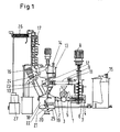
- FIG. 1 shows the scheme of the method according to the invention.
- the pump is designated, which has the material inlet 3 and the connection to the circulating oil 4 on the suction side 2.
- On the discharge side is the pressure line 5 which opens tangentially into the stirred tank 6.
- the agitator 7 has additional upward cleaning arms that coat the entire surface of the stirred tank.
- the stirred tank 6 is connected to a hydrocyclone 10 through a connecting pipe 9.
- a regulated control valve 11 is arranged, which regulates the pressure in the subsequent apparatuses.
- a further pump is arranged in this line, which is regulated by pressure controlled frequency converter with the pump 1.
- the hydrocyclone 10 has inside a voltage applied to the inner wall venturi 12, which also lowers the remaining pressure and increases the Abscheiderial.
- hydrocyclone Above the hydrocyclone is a safety container 13 with a level control 14 with oil level measurement 15.
- an agitator is arranged, which is driven by an electric motor and has cleaning arms for the lower part of the containment, the cyclone and underlying the cyclone container.
- the side of the safety container 13 is the product vapor line 16 for the diesel vapor generated to the distillation unit 17 with the condenser 26.
- the condenser 26 is a tube bundle water cooler, the water is recooled in the cooling circuit.
- any resulting water separates out, which is deposited separately via a conductivity sensor with a controlled discharge valve, so that no water is contained in the product.
- Diesel is discharged in the upper part of the column via the upper removal.
- the quality of the diesel is regulated via the reflux line via the return flow.
- the reflux line has a connection to the diesel reservoir of the power generator 27, which supplies power to the system. This consumes about 10% of the diesel produced for the self-powered and also generates the heat for the pre-drying and preheating of the oils by the exhaust gas of the
- All containers are provided for the purpose of facilitating the heating phase with an electric external heating.
- Below the hydrocyclone 10 is the separation vessel 18 with the inclined blades 19, which provide for a separation of not convertible into diesel components of the input materials.
- This separation tank 18 is connected to the intake pipe 2. At the bottom of the separation vessel 18 is a temperature measurement 19, which sets the discharge screw 20 in operation when the temperature by insulation with the
- the discharge screw 20 has a filter part 21 within the container, which allows the liquid portions to flow back through the filter screen 22 in the separating vessel 18 and an electrically heated carbonized part 23 outside the separating vessel 18, which evaporates the remaining oil components from the press cake. For this purpose, a temperature increase up to 600 ° C is provided. The escaping from the Schwelschnecke 23 oil vapors pass through the steam line 24 into the containment 13th
- the agitator (7) has additional upwardly extending cleaning arms, which coat the entire surface of the stirred tank, so both the lower part of the stirred tank with 1400 mm, and the upper part with a diameter of 500 mm.
- the stirred tank (6) is connected to a hydrocyclone (10) through a connecting pipe (9) having a diameter of 200 mm.
- a regulated control valve (11) is arranged, which regulates the pressure in the subsequent apparatuses.
- the hydrocyclone (10) has a diameter of 1,000 mm and inside a voltage applied to the inner wall venturi (12) with a narrowest cross-section of 100 x 200 mm, which also lowers the remaining pressure and increases the separation efficiency.
- hydrocyclone is a safety container (13) with a diameter of 2,000 mm of a level control (14) with oil level measurement (15).
- a level control (14) with oil level measurement (15) On the safety container (13), an agitator is arranged, which is driven by a 10 kW electric motor and has cleaning arms for the lower part of the containment, the cyclone and the underlying container under the cyclone.
- All containers are provided with an external electric heater with a total capacity of 50 kW for the purpose of facilitating the heating phase.
- This separation tank (18) is connected to the intake pipe (2) with a diameter of 200 mm.
- a temperature measurement (19) At the bottom of the separation vessel (18) is a temperature measurement (19), which sets the discharge screw (20) in operation when the
- the discharge screw (20) with a diameter of 80 mm and a capacity of 10 - 20 kg / h has a filter part (21) within the container, which flows back the liquid portions through the filter screen (22) in the separation vessel (18) and an electrically heated carbonized part (23) outside the separation vessel (18) with a heating power of 45 kW, which evaporates the remaining oil components from the press cake.
- a temperature increase up to 600 ° C is provided.
- the oil vapors escaping from the supercooling screw (23) pass via the steam line (24) into the safety container (13).
Description
- Die Erfindung beinhaltet ein Verfahren zur katalytischen Molekülverkürzung von Kohlenwasserstoffen bei Temperaturen von 300 bis 400°C mit alkalisch dotierten Aluminiumsilikaten als Katalysator mit einem Energieeintrag überwiegend in Form einer Kombination von Pumpen und Rührwerken mit einer angeschlossenen Abscheidung mineralischer Begleitstoffe.
- Bekannt ist die katalytische Depolymerisation mit einem speziellen Katalysator aus natriumdotierten Aluminiumsilikat aus dem Patent Nr.
DE 10049377 . Dabei wird mit dem Katalysator der kohlenwasserstoffhaltige Reststoff zu Diesel und Benzin gespalten. Die Beheizung für das Aufbringen der Spaltenergie, der Verdampfungsenergie des gespaltenen Kohlenwasserstoffes in Form von Diesel und Benzin und die Aufheizenergie, sowie die Wärmeverluste werden dabei durch die Beheizung durch die Wand aufgebracht. - Nachteil dieses Verfahrens ist die durch die Temperaturdifferenz durch die Wand notwendige Übertemperatur gegenüber der Reaktionstemperatur. Dadurch bildet sich immer etwas Reaktionskoks. Die Menge an Koks nimmt zu, wenn die Übertemperatur der Wand gegenüber dem Reaktionsgemisch ansteigt, d. h. wenn eine gewisse Produktionsleistung erreicht werden soll.
- Dieser Reaktionskoks reagiert nun mit dem natriumdotierten Aluminiumsilikat zu einem nichtreaktiven Rückstand, der die Anlage verschmutzt und die Reaktion zum Erliegen bringt. Dieses Reaktionsgemisch von dem Katalysator und dem Reaktionskoks verbindet sich mit der Wand der Anlage zu einem harten Rückstand und erfordert einen hohen Reinigungsaufwand in den Wartungsintervallen. Die Erfindung beschreibt somit nur einen Prozess, nicht jedoch ein wirtschaftliches Verfahren.
- Das wirtschaftliche Verfahren ist deshalb mit einer intensiven Beheizung der Wandung und damit aktiven Wärmeeintrag durch Beheizung durch die Wand nicht möglich. Die geringe Wärmeleitung des im Kreislauf befindlichen Reaktionsöles bedingt eine höhere Temperaturdifferenz zwischen der außen an der Wand befindlichen Beheizung zu der Reaktion im Öl, die die Spaltenergie (Depolymerisation), die Verdampfungsenergie und die Aufheizenergie benötigt.
- In dem Ölkreislauf wird bei Altöl und Teeren je kg verdampften Diesels ca. 0,4 kWh Energie für die Spaltung, Verdampfung und Aufheizung von der Eingangstemperatur von 250°C auf die Reaktionstemperatur 390°C benötigt. Bei dem Eintrag von Kunststoffen ist die Energie fast doppelt so hoch, da diese kalt eingetragen werden und die Schmelzenergie zusätzlich gebraucht wird.
- Überraschenderweise wurde nun ein Prozess des Wärmeeintrages und dazu angepasstes Katalysatorsystem gefunden, welche diese Nachteile vollkommen vermeiden. Das System transportiert nicht die Wärme durch die Wand, sondern setzt die Wärme direkt im Reaktionssystem frei.
- Der Energieeintrag erfolgt dabei in einem System von Pumpe und gegenläufig betriebenen. Rührsystem mit Abscheidung des Dieseldampfes in einem Hochgeschwindigkeitshydrozyklon. Die Rührsysteme dienen dabei auch der vollständigen Reinigung der im Kreislauf angeordneten Oberflächen.
- Auch der Katalysator wurde neu entwickelt. Nur für die Kunststoffe, Bitumen und Altöle wurde dabei die Dotierung eines volldurchkristallisierten Y-Moleküles mit Natrium als optimal ermittelt. Für die biologischen Einsatzstoffe, wie Fette und biologischen Öle wurde die Dotierung mit Kalzium als optimal entdeckt. Für die Umsetzung mit Holz ist die Dotierung mit Magnesium notwendig, um hochwertiges Diesel zu erzeugen. Für die hochhalogenhaltigen Stoffe, wie Trafoöl und PVC ist die Dotierung mit Kalium notwendig.
- Das Produkt der Anlage ist Dieselöl, da der Produktaustrag aus dem Kreislauf bei 300-400°C keine anderen, leichteren Produkte im System belässt. Dieses Produkt wird zu 10 % für die Erzeugung der Prozessenergien in Form von Strom über ein Stromerzeugungsaggregat eingesetzt. Der Vorteil dieser Energieumwandlung ist die gleichzeitige Lösung der Probleme mit dem in der Anlage in geringen Mengen entstehenden Gas, das in die Ansaugluft geleitet wird und die Wärmeenergie der Auspuffgase, die für die Vortrocknung und Vorwärmung der Eingangsstoffe verwendet wird.
-
Figur 1 zeigt das Schema des erfindungsgemäßen Verfahrens. Mit 1 ist die Pumpe bezeichnet, die auf der Ansaugseite 2 den Materialeintrag 3und den Anschluss an das Kreislauföl 4 besitzt. Auf der Austragseite befindet sich die Druckleitung 5 die tangential in den Rührbehälter 6 mündet. Dort ist ein Rührwerk 7 mit einer gegenläufigen Drehrichtung drehend, angetrieben durch den Elektromotor 8. Das Rührwerk 7 hat zusätzliche nach oben gehende Reinigungsarme, die die gesamte Oberfläche des Rührbehälters bestreichen. - Der Rührbehälter 6 ist durch eine Verbindungsrohrleitung 9 mit einem Hydrozyklon 10 verbunden. In der Verbindungsrohleitung ist ein geregeltes Stellventil 11 angeordnet, welches den Druck in den nachfolgenden Apparaten regelt. In einer speziellen Ausführung ist in dieser Leitung auch eine weitere Pumpe angeordnet, die druckgeregelt über Frequenzumrichter mit der Pumpe 1 geregelt wird. Der Hydrozyklon 10 hat im Inneren eine an der Innenwand anliegende Venturidüse 12, die ebenfalls den verbleibenden Überdruck absenkt und die Abscheidewirkung erhöht.
- Oberhalb des Hydrozyklons befindet sich ein Sicherheitsbehälter13 mit einer Füllstandsregelung 14 mit Ölstandsniveaumessung 15. Auf dem Sicherheitsbehälter 13 ist ein Rührwerk angeordnet, welches mit Elektromotor angetrieben wird und Reinigungsarme für den unteren Teil des Sicherheitsbehälters, dem Zyklon und dem unter dem Zyklon liegenden Behälter besitzt.
- Seitlich an dem Sicherheitsbehälter 13 ist die Produktdampfleitung 16 für den erzeugten Dieseldampf zur Destillationsanlage 17 mit dem Kondensator 26. Der Kondensator 26 ist ein Röhrenbündelwasserkühler, dessen Wasser im Kühlkreislauf rückgekühlt wird.
- In dem vorderen Teil des Kondensators 26 scheidet sich evtl. entstehendes Wasser ab, das über einen Leitfähigkeitssensor mit geregeltem Ablassventil separat abgeschieden wird, so dass in dem Produkt kein Wasser enthalten ist. Das Produkt
- Diesel wird im oberen Teil der Kolonne über die obere Entnahme abgeleitet. Die Qualität des Diesels wird über die Refluxleitung über die Rückflussmenge geregelt.
- Die Refluxleitung hat einen Anschluss an den Dieselvorratsbehälter des Stromgenerators 27, der die Anlage mit Strom versorgt. Dieser verbraucht ca. 10 % des erzeugten Diesels für die Eigenstromversorgung und erzeugt darüber hinaus die Wärme für die Vortrocknung und Vorwärmung der Öle durch das Auspuffgas des
- Motors.
- Alle Behälter sind zum Zwecke der Erleichterung der Anheizphase mit einer elektrischen Außenheizung versehen. Unterhalb des Hydrozyklons 10 befindet sich der Abscheidebehälter 18 mit den Schräglamellen 19, die für eine Separierung der nicht in Diesel umsetzbaren Bestandteile der Eingangsstoffe sorgen.
- Dieser Abscheidebehälter 18 ist mit dem Ansaugrohr 2 verbunden. Am Boden des Abscheidebehälters 18 befindet sich eine Temperaturmessung 19, die die Austragschnecke 20 in Betrieb setzt, wenn die Temperatur durch Isolation mit dem
- Reststoff unter einen Grenzwert in dem Temperaturmesser 25 absinkt.
- Die Austragschnecke 20 besitzt einen Filterteil 21 innerhalb des Behälters, der die flüssigen Anteile durch das Filtersieb 22 in den Abscheidebehälter 18 zurückfließen lässt und einen elektrisch geheizten Schwelteil 23 außerhalb des Abscheidebehälters 18, der die restlichen Ölanteile aus dem Presskuchen verdampfen lässt. Dazu ist eine Temperaturerhöhung auf bis zu 600°C vorgesehen. Die aus der Schwelschnecke 23 entweichenden Öldämpfe gelangen über die Dampfleitung 24 in den Sicherheitsbehälter 13.
- In einem Ausführungsbeispiel wird die Erfindung näher erläutert. Eine Kreiselpumpe mit 200 kW Antriebsleistung fördert über ein Ansaugleitung (2) 5.000 l/h Ansaugöl und über den Materialeintrag (3) 600 kg Reststoffe in Form von Altöl und Bitumen mit insgesamt 5.600 l/h in die Druckleitung (5) die tangential in den Rührbehälter (6) mit einem Durchmesser von 1.400 mm mündet. Dort ist ein Rührwerk 7 mit einer gegenläufigen Drehrichtung drehend, angetrieben durch den Elektromotor (8) mit 40 kW. Das Rührwerk (7) hat zusätzliche nach oben gehende Reinigungsarme, die die gesamte Oberfläche des Rührbehälters bestreichen, also sowohl des unteren Teiles des Rührbehälters mit 1400 mm, als auch dem oberen Teil mit einem Durchmesser von 500 mm.
- Der Rührbehälter (6) ist durch eine Verbindungsrohrleitung (9) mit einem Durchmesser von 200 mm mit einem Hydrozyklon (10) verbunden. In der Verbindungsrohleitung ist ein geregeltes Stellventil (11) angeordnet, welches den Druck in den nachfolgenden Apparaten regelt. Der Hydrozyklon (10) hat einen Durchmesser von 1.000 mm und im Inneren eine an der Innenwand anliegende Venturidüse (12) mit einem engsten Querschnitt von 100 x 200 mm, die ebenfalls den verbleibenden Überdruck absenkt und die Abscheidewirkung erhöht.
- Oberhalb des Hydrozyklons befindet sich ein Sicherheitsbehälter(13) mit einem Durchmesser von 2.000 mm einer Füllstandsregelung (14) mit Ölstandsniveaumessung (15). Auf dem Sicherheitsbehälter (13) ist ein Rührwerk angeordnet, welches mit Elektromotor mit 10 kW angetrieben wird und Reinigungsarme für den unteren Teil des Sicherheitsbehälters, dem Zyklon und dem unter dem Zyklon liegenden Behälter besitzt.
- Seitlich an dem Sicherheitsbehälter (13) ist die Produktdampfleitung (16) für den erzeugten Dieseldampf zur Destillationsanlage (17) mit einem Kolonnendurchmesser von 500 mm. Alle Behälter sind zum Zwecke der Erleichterung der Anheizphase mit einer elektrischen Außenheizung mit einer Gesamtleistung von insgesamt 50 kW versehen.
- Unterhalb des Hydrozyklons (10) befindet sich der Abscheidebehälter (18) mit 2.000 mm Durchmesser mit den Schräglamellen (19), die für eine Separierung der nicht in
- Diesel umsetzbaren Bestandteile der Eingangsstoffe sorgen. Dieser Abscheidebehälter (18) ist mit dem Ansaugrohr (2) mit 200 mm Durchmesser verbunden. Am Boden des Abscheidebehälters (18) befindet sich eine Temperaturmessung (19), die die Austragschnecke (20) in Betrieb setzt, wenn die
- Temperatur durch Isolation mit dem Reststoff unter einen Grenzwert absinkt.
- Die Austragschnecke (20) mit einem Durchmesser von 80 mm und einer Förderleistung von 10 - 20 kg/h besitzt einen Filterteil (21) innerhalb des Behälters, der die flüssigen Anteile durch das Filtersieb (22) in den Abscheidebehälter (18) zurückfließen lässt und einen elektrisch geheizten Schwelteil (23) außerhalb des Abscheidebehälters (18) mit einer Heizleistung von 45 kW, der die restlichen Ölanteile aus dem Presskuchen verdampfen lässt. Dazu ist eine Temperaturerhöhung auf bis zu 600°C vorgesehen. Die aus der Schwelschnecke (23) entweichenden Öldämpfe gelangen über die Dampfleitung (24) in den Sicherheitsbehälter (13).
-
- 1. Pumpe für Energieeintrag
- 2. Ansaugseite der Pumpe
- 3. Materialeintrag (input)
- 4. Zufuhr Kreislauföl (input 2)
- 5. Druckleitung tangential
- 6. Rührbehälter
- 7. Rührwerk (gegenläufig zur Druckleitung tangential)
- 8. Elektromotor für Rührwerk
- 9. Verbindungsrohrleitung zu Hydrozyklon
- 10. Hydrozyklon
- 11. Stellventil zur Druckregulierung
- 12. Venturidüse im Hydrozyklon innen anliegend
- 13. Sicherheitsbehälter
- 14. Füllstandsregelung,
- 15. Niveauanzeige und Regelung
- 16. Produktdampfleitung
- 17. Destillationsanlage
- 18. Abscheidebehälter
- 19. Schräglamellen im Abscheidebehälter
- 20. Austragschnecke
- 21. Filterteil der Austragschnecke
- 22. Filtersieb des Filterteiles der Austragschnecke
- 23. Schwelteil der Austragschnecke (bis 600°C)
- 24. Schweldampfleitung zum Sicherheitsbehälter
- 25. Temperaturmessung unterhalb der Feststoffabscheidung
- 26. Kondensator
- 27. Stromgenerator
Claims (6)
- Verfahren zur Erzeugung von Dieselöl durch eine katalytische Molekülverkürzung aus kohlenstoffhaltigen Reststoffen mittels eines alkalisch dotierten Aluminiumsilikats als Katalysator bei Temperaturen von 300-400°C, wobei zuerst ein Materialeintrag (3) und ein Kreislauföl (4) über eine Pumpe (1) tangential in einen Rührbehälter (6) zugeführt werden,
und mit den weiteren Verfahrensschritten einer Feststoffabscheidung (10) und einer Produktdestillation (17),
wobei der Hauptenergieeintrag für die Haupterwärmung über ein System erzeugt wird, das eine Strömungsenergie der wenigstens einen Pumpe (1) durch ein in dem Rührbehälter (6) betriebenes Rührwerk (7) mit einer der tangentialen Zuführung gegenläufigen Drehrichtung in Wärme umwandelt. - Verfahren nach Anspruch 1,
dadurch gekennzeichnet,
dass der Katalysator aus alkalisch dotiertem Aluminiumsilikat dotiert ist mit einem Element ausgewählt aus der Gruppe bestehend aus Kalium, Kalzium oder Magnesium. - Verfahren nach Anspruch 2,
dadurch gekennzeichnet,
dass ein mit Kalzium dotiertes Aluminiumsilikat als Katalysator für Reststoffen aus biologische Ersatzstoffe, wie Fette und biologische Öle, eingesetzt wird. - Verfahren nach Anspruch 2,
dadurch gekennzeichnet,
dass ein mit Magnesium dotiertes Aluminiumsilikat als Katalysator für Reststoffe aus Holz verwendet wird. - Verfahren nach Anspruch 2,
dadurch gekennzeichnet,
dass ein mit Kalium dotiertes Aluminiumsilikat als Katalysator für hochhalogenhaltige Reststoffe, wie Trafoöl und PVC, eingesetzt wird. - Verfahren nach einem der vorstehenden Ansprüche,
dadurch gekennzeichnet,
dass eine Temperatur- und Füllstandsregelung bereitgestellt wird, die miteinander vernetzt sind, wobei Zufuhr- und Eintragsystem so gesteuert werden, dass ein Füllstand im Rührbehälter beibehalten wird.
Priority Applications (1)
| Application Number | Priority Date | Filing Date | Title |
|---|---|---|---|
| CY20111101162T CY1112093T1 (el) | 2003-12-02 | 2011-11-25 | Πετρελαιο ντιζελ απο υπολειμματικα υλικα μεσω καταλυτικου αποπολυμερισμου με παροχη ενεργειας απο ενα συστημα αντλιων-αναδευτηρων |
Applications Claiming Priority (2)
| Application Number | Priority Date | Filing Date | Title |
|---|---|---|---|
| DE10356245 | 2003-12-02 | ||
| DE10356245A DE10356245B4 (de) | 2003-12-02 | 2003-12-02 | Verfahren zur Erzeugung von Dieselöl aus kohlenwasserstoffhaltigen Reststoffen sowie eine Vorrichtung zur Durchführung dieses Verfahrens |
Publications (2)
| Publication Number | Publication Date |
|---|---|
| EP1538191A1 EP1538191A1 (de) | 2005-06-08 |
| EP1538191B1 true EP1538191B1 (de) | 2011-08-31 |
Family
ID=34442397
Family Applications (1)
| Application Number | Title | Priority Date | Filing Date |
|---|---|---|---|
| EP04090070A Expired - Lifetime EP1538191B1 (de) | 2003-12-02 | 2004-02-26 | Dieselöl aus Reststoffen durch katalytische Depolymerisation mit dem Energieeintrag in einem Pumpen-Rührwerkssystem |
Country Status (12)
| Country | Link |
|---|---|
| US (1) | US7473348B2 (de) |
| EP (1) | EP1538191B1 (de) |
| JP (1) | JP2005163013A (de) |
| CN (1) | CN1624077A (de) |
| AT (1) | ATE522590T1 (de) |
| BR (1) | BRPI0400912B1 (de) |
| CA (1) | CA2474523A1 (de) |
| CY (1) | CY1112093T1 (de) |
| DE (1) | DE10356245B4 (de) |
| ES (1) | ES2376573T3 (de) |
| MX (1) | MXPA04002431A (de) |
| RU (1) | RU2360946C2 (de) |
Cited By (4)
| Publication number | Priority date | Publication date | Assignee | Title |
|---|---|---|---|---|
| WO2013021011A1 (en) | 2011-08-10 | 2013-02-14 | Irle S.R.L. | Apparatus and process for catalytic conversion of waste in combustible fluids |
| WO2016170000A1 (en) | 2015-04-22 | 2016-10-27 | Convecom S.R.L. | Method of thermochemical decomposition of waste |
| WO2019038276A1 (de) | 2017-08-23 | 2019-02-28 | Karl Morgenbesser | Vorrichtung und verfahren zur katalytischen und/order drucklosen verölung |
| US10723956B2 (en) | 2017-07-21 | 2020-07-28 | 1888711 Alberta Inc. | Enhanced distillate oil recovery from thermal processing and catalytic cracking of biomass slurry |
Families Citing this family (42)
| Publication number | Priority date | Publication date | Assignee | Title |
|---|---|---|---|---|
| US7344622B2 (en) * | 2003-04-08 | 2008-03-18 | Grispin Charles W | Pyrolytic process and apparatus for producing enhanced amounts of aromatic compounds |
| WO2006043924A1 (en) * | 2004-10-13 | 2006-04-27 | Charlie Holding Intellectual Property, Inc. | Pyrolytic process and apparatus for producing enhanced amounts of aromatic compounds |
| EP1745840A1 (de) * | 2005-07-22 | 2007-01-24 | Services Petroliers Schlumberger | Vorrichtung und Verfahren zum Mischen eines flüssigen und eines fliessfähigen pulverförmigen Materials zur Herstellung einer Suspension |
| US20110235460A1 (en) * | 2005-07-22 | 2011-09-29 | Schlumberger Technology Corporation | Method and apparatus to optimize the mixing process |
| DE102005056735B3 (de) | 2005-11-29 | 2006-08-10 | Koch, Christian, Dr. | Hochleistungskammermischer für katalytische Ölsuspensionen als Reaktor für die Depolymerisation und Polymerisation von kohlenwasserstoffhaltigen Reststoffen zu Mitteldestillat im Kreislauf |
| EP2134812A1 (de) * | 2006-11-20 | 2009-12-23 | Christian Koch | Hochleistungskammermischer für katalytische ölsuspensionen |
| DE102006060224A1 (de) | 2006-12-20 | 2008-07-03 | Buchert, Jürgen | Katalytische Erzeugungsanlage für Dieselöl |
| DE102006061217B3 (de) * | 2006-12-22 | 2008-06-05 | Buchert, Jürgen | Verfahren zur thermischen Aufbereitung von Klärschlamm und Einrichtung zur Durchführung des Verfahrens |
| ITBO20070104A1 (it) * | 2007-02-21 | 2008-08-22 | Kdvsistemi Brevetti S R L | Apparato per la produzione di combustibile sintetico |
| DE102007011763B3 (de) * | 2007-03-10 | 2008-11-20 | Buchert, Jürgen | Verfahren zur katalytischen Aufbereitung von Klärschlamm und Einrichtung zur Durchführung des Verfahrens |
| US7491856B2 (en) | 2007-06-27 | 2009-02-17 | H R D Corporation | Method of making alkylene glycols |
| US8304584B2 (en) | 2007-06-27 | 2012-11-06 | H R D Corporation | Method of making alkylene glycols |
| US7696391B2 (en) * | 2007-06-27 | 2010-04-13 | H R D Corporation | System and process for production of nitrobenzene |
| ITBO20070770A1 (it) * | 2007-11-22 | 2009-05-23 | Vuzeta Brevetti S R L | Metodo e apparato per il trattamento di materiali di rifiuto |
| DE102008003209B3 (de) * | 2008-01-05 | 2009-06-04 | Relux Umwelt Gmbh | Verfahren und Vorrichtung zur Erzeugung von Mitteldestillat aus kohlenwasserstoffhaltigen Energieträgern |
| ITBO20080072A1 (it) * | 2008-02-01 | 2009-08-02 | Vuzeta Brevetti S R L | Apparato per il trattamento di materiali di rifiuto |
| DE102008013241B4 (de) * | 2008-03-08 | 2010-05-20 | Buchert, Jürgen | Verfahren zur thermischen Aufbereitung von Biomasse und Einrichtung zur Durchführung des Verfahrens |
| US20090267349A1 (en) | 2008-04-23 | 2009-10-29 | Spitzauer Michael P | Production Processes, Systems, Methods, and Apparatuses |
| KR20120009428A (ko) * | 2009-02-20 | 2012-01-31 | 알파패트 이스태블리시먼트 | 기조절된 슬러리 같은 잔여물로부터 촉매식 오일링 반응들을 위한 유압식 개스킷을 갖는 오일 반응기 진공 펌프 |
| DE102009033216A1 (de) | 2009-07-15 | 2011-01-27 | Brümmer, Heinz | Vorrichtung und Verfahren zur Herstellung von Leichtölen aus Biomasse und kohlenwasserstoffhaltigen Stoffen mittels Verpressen der Reaktionsmasse zusammen mit einem zeolithischen Katalysator als Reaktionsbeschleuniger zu Pellets und anschließender Molekülverkürzung der Reaktionsmasse durch von Mikrowellenstrahlung initiiertem Plasma in einem Flachbettreaktor |
| CA2805521A1 (en) | 2010-07-26 | 2012-02-09 | Emil A. J. Wieser-Linhart | Facility and method for producing fuels from biomass/plastic mixtures |
| WO2013057735A1 (en) | 2011-10-21 | 2013-04-25 | Turlapati Raghavendra Rao | "process and plant for conversion of segregated or unsegregated carbonaceous homogeneous and non- homogeneous waste feed into hydrocarbon fuels" |
| PL398335A1 (pl) | 2012-03-07 | 2013-09-16 | Idea Spólka Z Ograniczona Odpowiedzialnoscia | Sposób wytwarzania uszlachetnionego paliwa do silników wysokopreznych oraz uszlachetnione paliwo do silników wysokopreznych |
| DE102012204657A1 (de) | 2012-03-22 | 2013-09-26 | Wilfried Schraufstetter | Modular aufgebauten Reaktor zur Verflüssigung von Abfallstoffen mit horizontal geteilter Heizmittelführung |
| DE102012010763A1 (de) | 2012-03-26 | 2013-09-26 | Axel Trautmann | Vorrichtung und Verfahren zur katalytischen Depolymerisation von Kohlenstoff enthaltendem Material |
| PL399654A1 (pl) | 2012-06-25 | 2014-01-07 | Green Power Spólka Z Ograniczona Odpowiedzialnoscia Spólka W Organizacji | Sposób wytwarzania uszlachetnionego biokomponentu do biopaliw oraz uszlachetniony biokomponent do biopaliw |
| PL400489A1 (pl) | 2012-08-23 | 2014-03-03 | Glob Investment Spólka Z Ograniczona Odpowiedzialnoscia | Sposób wytwarzania paliwa oraz paliwo |
| PL400488A1 (pl) | 2012-08-23 | 2014-03-03 | Glob Investment Spólka Z Ograniczona Odpowiedzialnoscia | Sposób wytwarzania paliwa oraz paliwo |
| WO2014106650A2 (de) | 2013-01-03 | 2014-07-10 | EZER, Argun | Verfahren und vorrichtungen zur verölung von kohlenwasserstoffhaltigem eingangsmaterial |
| ES2503442B1 (es) * | 2013-04-03 | 2015-07-15 | Jordi HUGUET FARRE | Procedimiento de valorización integral de residuos para la obtención de combustible diesel sintético |
| WO2015007344A1 (de) * | 2013-07-19 | 2015-01-22 | Catalytec | Verfahren und vorrichtung zur gewinnung einer kohlenwasserstoffe-haltigen zusammensetzung aus reststoffen |
| WO2015007343A1 (de) * | 2013-07-19 | 2015-01-22 | Catalytec | Verfahren und vorrichtung zur gewinnung einer kohlenwasserstoffe-haltigen zusammensetzung aus reststoffen |
| FR3061492B1 (fr) * | 2017-01-03 | 2019-05-24 | D.M.S | Procede de production de carburant par craquage catalytique d'un materiau solide hydrocarbone et dispositif pour sa mise en œuvre |
| EP3609611A1 (de) * | 2017-04-11 | 2020-02-19 | Innoil AG | Reaktionsbehälter |
| CA3086818A1 (en) | 2017-12-13 | 2019-06-20 | Karl Ip Holdings Inc. | Low-pressure catalytic conversion of used motor oil to diesel fuel |
| EP3599342B1 (de) | 2018-07-27 | 2021-03-03 | Alphakat Holding International Ltd. | Plattform zur ölförderung |
| DE102019001696A1 (de) | 2019-03-11 | 2020-09-17 | Olaf Heimbürge | Anlage und Verfahren zur katalytischen Herstellung von Dieselölen aus organischen Materialien |
| DE102019001702A1 (de) | 2019-03-11 | 2020-09-17 | Olaf Heimbürge | Anlage und Verfahren zur katalytischen Herstellung von Dieselölen aus organischen Materialien |
| DE102019001697A1 (de) | 2019-03-11 | 2020-09-17 | Olaf Heimbürge | Anlage und Verfahren zur katalytischen Herstellung von Dieselölen aus organischen Materialien |
| US10953381B1 (en) | 2020-03-24 | 2021-03-23 | Tge Ip Llc | Chemical reactor with high speed rotary mixing, for catalytic thermal conversion of organic materials into diesel and other liquid fuels, and applications thereof |
| DE102020004964A1 (de) | 2020-08-14 | 2022-02-17 | Timon Kasielke | Anlage und Verfahren zur katalytischen Herstellung von Dieselölen aus organischen Materialien |
| US20240047015A1 (en) | 2021-01-20 | 2024-02-08 | Jems, Energetska Družba, D.O.O. | Systems and methods for plant process optimisation |
Citations (1)
| Publication number | Priority date | Publication date | Assignee | Title |
|---|---|---|---|---|
| US2105191A (en) * | 1938-01-11 | Method for cracking petroleum oils |
Family Cites Families (13)
| Publication number | Priority date | Publication date | Assignee | Title |
|---|---|---|---|---|
| US1754136A (en) * | 1924-07-08 | 1930-04-08 | Woidich Francis Sales | Process and apparatus for converting heavy hydrocarbon oils into lighter products |
| US1904586A (en) * | 1926-12-22 | 1933-04-18 | Ig Farbenindustrie Ag | Conversion of carbonaceous solids into valuable liquid products |
| US2764147A (en) * | 1951-02-23 | 1956-09-25 | Northrop Aircraft Inc | Frictional heater for hydraulic system |
| BE523969A (de) * | 1952-11-08 | |||
| US4300009A (en) * | 1978-12-28 | 1981-11-10 | Mobil Oil Corporation | Conversion of biological material to liquid fuels |
| US5073251A (en) * | 1982-10-19 | 1991-12-17 | Daniels Ludlow S | Method of an apparatus for recovering oil from solid hydrocarbonaceous material |
| FR2560204A1 (fr) * | 1984-02-24 | 1985-08-30 | Elf Aquitaine | Procede et installation de distillation de petrole par separations progressives |
| US4663025A (en) * | 1986-08-14 | 1987-05-05 | Phillips Petroleum Company | Catalytic cracking processes |
| US4781151A (en) * | 1986-11-24 | 1988-11-01 | Wolpert Jr George H | Flameless heat source |
| US5244565A (en) * | 1990-08-17 | 1993-09-14 | Uop | Integrated process for the production of distillate hydrocarbon |
| DE4311034A1 (de) * | 1993-04-03 | 1994-10-06 | Veba Oel Ag | Verfahren zur Gewinnung von Chemierohstoffen und Kraftstoffkomponenten aus Alt- oder Abfallkunststoff |
| DE10049377C2 (de) * | 2000-10-05 | 2002-10-31 | Evk Dr Oberlaender Gmbh & Co K | Katalytische Erzeugung von Dieselöl und Benzinen aus kohlenwasserstoffhaltigen Abfällen und Ölen |
| RU2184136C1 (ru) * | 2001-01-17 | 2002-06-27 | Открытое акционерное общество "Эттис" | Способ получения светлых нефтепродуктов и установка для его осуществления |
-
2003
- 2003-12-02 DE DE10356245A patent/DE10356245B4/de not_active Expired - Fee Related
-
2004
- 2004-02-26 AT AT04090070T patent/ATE522590T1/de active
- 2004-02-26 EP EP04090070A patent/EP1538191B1/de not_active Expired - Lifetime
- 2004-02-26 ES ES04090070T patent/ES2376573T3/es not_active Expired - Lifetime
- 2004-03-15 MX MXPA04002431A patent/MXPA04002431A/es active IP Right Grant
- 2004-03-23 CN CNA2004100302703A patent/CN1624077A/zh active Pending
- 2004-03-30 RU RU2004109567/04A patent/RU2360946C2/ru active IP Right Revival
- 2004-03-31 BR BRPI0400912-6B1A patent/BRPI0400912B1/pt not_active IP Right Cessation
- 2004-07-15 CA CA002474523A patent/CA2474523A1/en not_active Abandoned
- 2004-07-15 US US10/891,971 patent/US7473348B2/en active Active - Reinstated
- 2004-10-08 JP JP2004295764A patent/JP2005163013A/ja active Pending
-
2011
- 2011-11-25 CY CY20111101162T patent/CY1112093T1/el unknown
Patent Citations (1)
| Publication number | Priority date | Publication date | Assignee | Title |
|---|---|---|---|---|
| US2105191A (en) * | 1938-01-11 | Method for cracking petroleum oils |
Cited By (6)
| Publication number | Priority date | Publication date | Assignee | Title |
|---|---|---|---|---|
| WO2013021011A1 (en) | 2011-08-10 | 2013-02-14 | Irle S.R.L. | Apparatus and process for catalytic conversion of waste in combustible fluids |
| WO2016170000A1 (en) | 2015-04-22 | 2016-10-27 | Convecom S.R.L. | Method of thermochemical decomposition of waste |
| US10723956B2 (en) | 2017-07-21 | 2020-07-28 | 1888711 Alberta Inc. | Enhanced distillate oil recovery from thermal processing and catalytic cracking of biomass slurry |
| US10961465B2 (en) | 2017-07-21 | 2021-03-30 | 1888711 Alberta Inc. | Enhanced distillate oil recovery from thermal processing and catalytic cracking of biomass slurry |
| US11859134B2 (en) | 2017-07-21 | 2024-01-02 | Cielo Waste Solutions Corp. | Enhanced distillate oil recovery from thermal processing and catalytic cracking of biomass slurry |
| WO2019038276A1 (de) | 2017-08-23 | 2019-02-28 | Karl Morgenbesser | Vorrichtung und verfahren zur katalytischen und/order drucklosen verölung |
Also Published As
| Publication number | Publication date |
|---|---|
| CY1112093T1 (el) | 2015-11-04 |
| US7473348B2 (en) | 2009-01-06 |
| JP2005163013A (ja) | 2005-06-23 |
| RU2360946C2 (ru) | 2009-07-10 |
| BRPI0400912B1 (pt) | 2015-01-27 |
| CN1624077A (zh) | 2005-06-08 |
| DE10356245A1 (de) | 2005-07-21 |
| CA2474523A1 (en) | 2005-06-02 |
| DE10356245B4 (de) | 2007-01-25 |
| US20050115871A1 (en) | 2005-06-02 |
| RU2004109567A (ru) | 2005-10-20 |
| BRPI0400912A (pt) | 2005-08-30 |
| ATE522590T1 (de) | 2011-09-15 |
| MXPA04002431A (es) | 2005-09-08 |
| ES2376573T3 (es) | 2012-03-15 |
| EP1538191A1 (de) | 2005-06-08 |
Similar Documents
| Publication | Publication Date | Title |
|---|---|---|
| EP1538191B1 (de) | Dieselöl aus Reststoffen durch katalytische Depolymerisation mit dem Energieeintrag in einem Pumpen-Rührwerkssystem | |
| DE102005056735B3 (de) | Hochleistungskammermischer für katalytische Ölsuspensionen als Reaktor für die Depolymerisation und Polymerisation von kohlenwasserstoffhaltigen Reststoffen zu Mitteldestillat im Kreislauf | |
| DE69920489T2 (de) | Integriertes lösungsmittelentasphaltierungs- und vergasungsverfahren | |
| DE102005010151B3 (de) | Verfahren zum katalytischen Depolymerisieren von kohlenwasserstoffhaltigen Rückständen sowie Vorrichtung zum Durchführen dieses Verfahrens | |
| WO2008022790A2 (de) | Verfahren und vorrichtung zum aufbereiten von kunststoffhaltigen abfällen | |
| EP1707614A1 (de) | Thermisches oder katalytisches Spaltverfahren für Kohlenwasserstoffeinsätze und entsprechendes System | |
| US20120217149A1 (en) | Decomposition of waste plastics | |
| DE102006061217B3 (de) | Verfahren zur thermischen Aufbereitung von Klärschlamm und Einrichtung zur Durchführung des Verfahrens | |
| DE102008003209B3 (de) | Verfahren und Vorrichtung zur Erzeugung von Mitteldestillat aus kohlenwasserstoffhaltigen Energieträgern | |
| EP2161299A1 (de) | Thermokatalytische Depolymerisation von Kunststoffabfällen, Anlage für thermokatalytische Depolymerisation von Kunststoffabfällen und Reaktor für thermokatalytische Depolymerisation von Kunststoffabfällen | |
| CN109721221A (zh) | 污油泥处理系统及方法 | |
| WO2004092305A1 (de) | Verfahren und vorrichtung zur katalytischen behandlung von reststoffen in kontinuierlich gereinigten und beheizten rohrbündelreaktoren | |
| US4636318A (en) | Chemical reformer | |
| DE102010060675B4 (de) | Verfahren und Anlage zur Gewinnung von Dieselöl aus kohlenwasserstoffhaltigen Roh- und Reststoffen | |
| EP2082007A1 (de) | Anlage und verfahren zur erzeugung von treibstoffen aus biogenen rohstoffen | |
| CN102533320B (zh) | 一种高沥青质含量重油的加工方法 | |
| DE102007051373B4 (de) | Verfahren und Vorrichtung zur Gewinnung von Diesel oder Heizöl aus kohlenwasserstoffhaltigen Rückständen | |
| US7736469B2 (en) | Production of hydrocarbon fuel | |
| EP3036309A1 (de) | Zwangsgasrückführung in raffinationsprozessen einer späteren phase und reaktoren | |
| WO1985002606A1 (en) | Chemical reformer | |
| CH706818A2 (de) | Verfahren und Vorrichtung zu Pyrolyse von kohlenstoffhaltiger Organik, aufgelöst in einem heissen Ölbad unter Vakuum und Sauerstoffausschluss mit Beigabe von Katalysatoren zur Erzeugung von Flüssigkraftstoffen, Koks oder Holzkohle und Brenngasen zur Deckung des Prozessenergiebedarfs. | |
| CH706819A2 (de) | Verfahren und Vorrichtung zu Pyrolyse von kohlenstoffhaltiger Organik, aufgelöst in einem heissen Ölbad unter Vakuum und Sauerstoffausschluss mit Beigabe von Katalysatoren zur Erzeugung von Flüssigkraftstoffen, Koks oder Holzkohle und Brenngasen zur Deckung des Prozessenergiebedarfs. |
Legal Events
| Date | Code | Title | Description |
|---|---|---|---|
| PUAI | Public reference made under article 153(3) epc to a published international application that has entered the european phase |
Free format text: ORIGINAL CODE: 0009012 |
|
| AK | Designated contracting states |
Kind code of ref document: A1 Designated state(s): AT BE BG CH CY CZ DE DK EE ES FI FR GB GR HU IE IT LI LU MC NL PT RO SE SI SK TR |
|
| AX | Request for extension of the european patent |
Extension state: AL HR LT LV MK |
|
| 17P | Request for examination filed |
Effective date: 20050622 |
|
| AKX | Designation fees paid |
Designated state(s): AT BE BG CH CY CZ DE DK EE ES FI FR GB GR HU IE IT LI LU MC NL PT RO SE SI SK TR |
|
| AXX | Extension fees paid |
Extension state: LT Payment date: 20050622 Extension state: AL Payment date: 20050622 Extension state: MK Payment date: 20050622 Extension state: LV Payment date: 20050622 |
|
| GRAP | Despatch of communication of intention to grant a patent |
Free format text: ORIGINAL CODE: EPIDOSNIGR1 |
|
| GRAS | Grant fee paid |
Free format text: ORIGINAL CODE: EPIDOSNIGR3 |
|
| GRAA | (expected) grant |
Free format text: ORIGINAL CODE: 0009210 |
|
| AK | Designated contracting states |
Kind code of ref document: B1 Designated state(s): AT BE BG CH CY CZ DE DK EE ES FI FR GB GR HU IE IT LI LU MC NL PT RO SE SI SK TR |
|
| AX | Request for extension of the european patent |
Extension state: AL LT LV MK |
|
| REG | Reference to a national code |
Ref country code: CH Ref legal event code: EP Ref country code: GB Ref legal event code: FG4D Free format text: NOT ENGLISH |
|
| REG | Reference to a national code |
Ref country code: IE Ref legal event code: FG4D Free format text: LANGUAGE OF EP DOCUMENT: GERMAN |
|
| REG | Reference to a national code |
Ref country code: DE Ref legal event code: R096 Ref document number: 502004012835 Country of ref document: DE Effective date: 20111027 |
|
| REG | Reference to a national code |
Ref country code: SE Ref legal event code: TRGR |
|
| REG | Reference to a national code |
Ref country code: NL Ref legal event code: T3 |
|
| LTIE | Lt: invalidation of european patent or patent extension |
Effective date: 20110831 |
|
| PG25 | Lapsed in a contracting state [announced via postgrant information from national office to epo] |
Ref country code: SI Free format text: LAPSE BECAUSE OF FAILURE TO SUBMIT A TRANSLATION OF THE DESCRIPTION OR TO PAY THE FEE WITHIN THE PRESCRIBED TIME-LIMIT Effective date: 20110831 |
|
| REG | Reference to a national code |
Ref country code: GR Ref legal event code: EP Ref document number: 20110402808 Country of ref document: GR Effective date: 20120117 |
|
| REG | Reference to a national code |
Ref country code: ES Ref legal event code: FG2A Ref document number: 2376573 Country of ref document: ES Kind code of ref document: T3 Effective date: 20120315 |
|
| REG | Reference to a national code |
Ref country code: IE Ref legal event code: FD4D |
|
| PG25 | Lapsed in a contracting state [announced via postgrant information from national office to epo] |
Ref country code: IE Free format text: LAPSE BECAUSE OF FAILURE TO SUBMIT A TRANSLATION OF THE DESCRIPTION OR TO PAY THE FEE WITHIN THE PRESCRIBED TIME-LIMIT Effective date: 20110831 Ref country code: SK Free format text: LAPSE BECAUSE OF FAILURE TO SUBMIT A TRANSLATION OF THE DESCRIPTION OR TO PAY THE FEE WITHIN THE PRESCRIBED TIME-LIMIT Effective date: 20110831 |
|
| PG25 | Lapsed in a contracting state [announced via postgrant information from national office to epo] |
Ref country code: PT Free format text: LAPSE BECAUSE OF FAILURE TO SUBMIT A TRANSLATION OF THE DESCRIPTION OR TO PAY THE FEE WITHIN THE PRESCRIBED TIME-LIMIT Effective date: 20120102 Ref country code: EE Free format text: LAPSE BECAUSE OF FAILURE TO SUBMIT A TRANSLATION OF THE DESCRIPTION OR TO PAY THE FEE WITHIN THE PRESCRIBED TIME-LIMIT Effective date: 20110831 Ref country code: RO Free format text: LAPSE BECAUSE OF FAILURE TO SUBMIT A TRANSLATION OF THE DESCRIPTION OR TO PAY THE FEE WITHIN THE PRESCRIBED TIME-LIMIT Effective date: 20110831 |
|
| PG25 | Lapsed in a contracting state [announced via postgrant information from national office to epo] |
Ref country code: DK Free format text: LAPSE BECAUSE OF FAILURE TO SUBMIT A TRANSLATION OF THE DESCRIPTION OR TO PAY THE FEE WITHIN THE PRESCRIBED TIME-LIMIT Effective date: 20110831 |
|
| PLBE | No opposition filed within time limit |
Free format text: ORIGINAL CODE: 0009261 |
|
| STAA | Information on the status of an ep patent application or granted ep patent |
Free format text: STATUS: NO OPPOSITION FILED WITHIN TIME LIMIT |
|
| REG | Reference to a national code |
Ref country code: HU Ref legal event code: AG4A Ref document number: E013302 Country of ref document: HU |
|
| 26N | No opposition filed |
Effective date: 20120601 |
|
| REG | Reference to a national code |
Ref country code: DE Ref legal event code: R097 Ref document number: 502004012835 Country of ref document: DE Effective date: 20120601 |
|
| PG25 | Lapsed in a contracting state [announced via postgrant information from national office to epo] |
Ref country code: MC Free format text: LAPSE BECAUSE OF NON-PAYMENT OF DUE FEES Effective date: 20120229 |
|
| PG25 | Lapsed in a contracting state [announced via postgrant information from national office to epo] |
Ref country code: CY Free format text: LAPSE BECAUSE OF NON-PAYMENT OF DUE FEES Effective date: 20120226 |
|
| PG25 | Lapsed in a contracting state [announced via postgrant information from national office to epo] |
Ref country code: HU Free format text: LAPSE BECAUSE OF NON-PAYMENT OF DUE FEES Effective date: 20120227 |
|
| PG25 | Lapsed in a contracting state [announced via postgrant information from national office to epo] |
Ref country code: BG Free format text: LAPSE BECAUSE OF FAILURE TO SUBMIT A TRANSLATION OF THE DESCRIPTION OR TO PAY THE FEE WITHIN THE PRESCRIBED TIME-LIMIT Effective date: 20111130 |
|
| PG25 | Lapsed in a contracting state [announced via postgrant information from national office to epo] |
Ref country code: LU Free format text: LAPSE BECAUSE OF NON-PAYMENT OF DUE FEES Effective date: 20120226 |
|
| PGFP | Annual fee paid to national office [announced via postgrant information from national office to epo] |
Ref country code: CH Payment date: 20150226 Year of fee payment: 12 Ref country code: DE Payment date: 20150210 Year of fee payment: 12 |
|
| PGFP | Annual fee paid to national office [announced via postgrant information from national office to epo] |
Ref country code: SE Payment date: 20150226 Year of fee payment: 12 |
|
| REG | Reference to a national code |
Ref country code: FR Ref legal event code: PLFP Year of fee payment: 12 |
|
| REG | Reference to a national code |
Ref country code: FR Ref legal event code: PLFP Year of fee payment: 13 |
|
| PGFP | Annual fee paid to national office [announced via postgrant information from national office to epo] |
Ref country code: CZ Payment date: 20160223 Year of fee payment: 13 Ref country code: ES Payment date: 20160322 Year of fee payment: 13 |
|
| PGFP | Annual fee paid to national office [announced via postgrant information from national office to epo] |
Ref country code: GR Payment date: 20160226 Year of fee payment: 13 Ref country code: NL Payment date: 20160226 Year of fee payment: 13 Ref country code: GB Payment date: 20160322 Year of fee payment: 13 Ref country code: BE Payment date: 20160322 Year of fee payment: 13 Ref country code: AT Payment date: 20160226 Year of fee payment: 13 Ref country code: FI Payment date: 20160318 Year of fee payment: 13 Ref country code: FR Payment date: 20160322 Year of fee payment: 13 |
|
| PGFP | Annual fee paid to national office [announced via postgrant information from national office to epo] |
Ref country code: IT Payment date: 20160318 Year of fee payment: 13 |
|
| REG | Reference to a national code |
Ref country code: DE Ref legal event code: R119 Ref document number: 502004012835 Country of ref document: DE |
|
| REG | Reference to a national code |
Ref country code: CH Ref legal event code: PL |
|
| REG | Reference to a national code |
Ref country code: SE Ref legal event code: EUG |
|
| PG25 | Lapsed in a contracting state [announced via postgrant information from national office to epo] |
Ref country code: CH Free format text: LAPSE BECAUSE OF NON-PAYMENT OF DUE FEES Effective date: 20160229 Ref country code: LI Free format text: LAPSE BECAUSE OF NON-PAYMENT OF DUE FEES Effective date: 20160229 |
|
| PG25 | Lapsed in a contracting state [announced via postgrant information from national office to epo] |
Ref country code: SE Free format text: LAPSE BECAUSE OF NON-PAYMENT OF DUE FEES Effective date: 20160227 |
|
| PG25 | Lapsed in a contracting state [announced via postgrant information from national office to epo] |
Ref country code: DE Free format text: LAPSE BECAUSE OF NON-PAYMENT OF DUE FEES Effective date: 20160901 |
|
| PG25 | Lapsed in a contracting state [announced via postgrant information from national office to epo] |
Ref country code: BE Free format text: LAPSE BECAUSE OF NON-PAYMENT OF DUE FEES Effective date: 20170228 |
|
| REG | Reference to a national code |
Ref country code: NL Ref legal event code: MM Effective date: 20170301 |
|
| REG | Reference to a national code |
Ref country code: AT Ref legal event code: MM01 Ref document number: 522590 Country of ref document: AT Kind code of ref document: T Effective date: 20170226 |
|
| GBPC | Gb: european patent ceased through non-payment of renewal fee |
Effective date: 20170226 |
|
| PG25 | Lapsed in a contracting state [announced via postgrant information from national office to epo] |
Ref country code: CZ Free format text: LAPSE BECAUSE OF NON-PAYMENT OF DUE FEES Effective date: 20170226 Ref country code: AT Free format text: LAPSE BECAUSE OF NON-PAYMENT OF DUE FEES Effective date: 20170226 Ref country code: FI Free format text: LAPSE BECAUSE OF NON-PAYMENT OF DUE FEES Effective date: 20170226 Ref country code: GR Free format text: LAPSE BECAUSE OF NON-PAYMENT OF DUE FEES Effective date: 20170906 |
|
| PG25 | Lapsed in a contracting state [announced via postgrant information from national office to epo] |
Ref country code: NL Free format text: LAPSE BECAUSE OF NON-PAYMENT OF DUE FEES Effective date: 20170301 |
|
| REG | Reference to a national code |
Ref country code: FR Ref legal event code: ST Effective date: 20171031 |
|
| PG25 | Lapsed in a contracting state [announced via postgrant information from national office to epo] |
Ref country code: FR Free format text: LAPSE BECAUSE OF NON-PAYMENT OF DUE FEES Effective date: 20170228 |
|
| REG | Reference to a national code |
Ref country code: BE Ref legal event code: MM Effective date: 20170228 |
|
| PG25 | Lapsed in a contracting state [announced via postgrant information from national office to epo] |
Ref country code: IT Free format text: LAPSE BECAUSE OF NON-PAYMENT OF DUE FEES Effective date: 20170226 Ref country code: GB Free format text: LAPSE BECAUSE OF NON-PAYMENT OF DUE FEES Effective date: 20170226 |
|
| REG | Reference to a national code |
Ref country code: ES Ref legal event code: FD2A Effective date: 20180705 |
|
| PG25 | Lapsed in a contracting state [announced via postgrant information from national office to epo] |
Ref country code: ES Free format text: LAPSE BECAUSE OF NON-PAYMENT OF DUE FEES Effective date: 20170227 |
|
| PGFP | Annual fee paid to national office [announced via postgrant information from national office to epo] |
Ref country code: TR Payment date: 20230201 Year of fee payment: 20 |