EP1542595B1 - Oval dilator and retractor set - Google Patents
Oval dilator and retractor set Download PDFInfo
- Publication number
- EP1542595B1 EP1542595B1 EP03796334A EP03796334A EP1542595B1 EP 1542595 B1 EP1542595 B1 EP 1542595B1 EP 03796334 A EP03796334 A EP 03796334A EP 03796334 A EP03796334 A EP 03796334A EP 1542595 B1 EP1542595 B1 EP 1542595B1
- Authority
- EP
- European Patent Office
- Prior art keywords
- dilator
- retractor
- tube
- tissue
- circular cross
- Prior art date
- Legal status (The legal status is an assumption and is not a legal conclusion. Google has not performed a legal analysis and makes no representation as to the accuracy of the status listed.)
- Expired - Lifetime
Links
Images


Classifications
-
- A—HUMAN NECESSITIES
- A61—MEDICAL OR VETERINARY SCIENCE; HYGIENE
- A61B—DIAGNOSIS; SURGERY; IDENTIFICATION
- A61B17/00—Surgical instruments, devices or methods, e.g. tourniquets
- A61B17/56—Surgical instruments or methods for treatment of bones or joints; Devices specially adapted therefor
-
- A—HUMAN NECESSITIES
- A61—MEDICAL OR VETERINARY SCIENCE; HYGIENE
- A61B—DIAGNOSIS; SURGERY; IDENTIFICATION
- A61B17/00—Surgical instruments, devices or methods, e.g. tourniquets
- A61B17/34—Trocars; Puncturing needles
- A61B17/3417—Details of tips or shafts, e.g. grooves, expandable, bendable; Multiple coaxial sliding cannulas, e.g. for dilating
- A61B17/3421—Cannulas
-
- A—HUMAN NECESSITIES
- A61—MEDICAL OR VETERINARY SCIENCE; HYGIENE
- A61B—DIAGNOSIS; SURGERY; IDENTIFICATION
- A61B17/00—Surgical instruments, devices or methods, e.g. tourniquets
- A61B17/02—Surgical instruments, devices or methods, e.g. tourniquets for holding wounds open; Tractors
-
- A—HUMAN NECESSITIES
- A61—MEDICAL OR VETERINARY SCIENCE; HYGIENE
- A61B—DIAGNOSIS; SURGERY; IDENTIFICATION
- A61B17/00—Surgical instruments, devices or methods, e.g. tourniquets
- A61B17/16—Bone cutting, breaking or removal means other than saws, e.g. Osteoclasts; Drills or chisels for bones; Trepans
- A61B17/17—Guides or aligning means for drills, mills, pins or wires
- A61B17/1739—Guides or aligning means for drills, mills, pins or wires specially adapted for particular parts of the body
- A61B17/1757—Guides or aligning means for drills, mills, pins or wires specially adapted for particular parts of the body for the spine
-
- A—HUMAN NECESSITIES
- A61—MEDICAL OR VETERINARY SCIENCE; HYGIENE
- A61B—DIAGNOSIS; SURGERY; IDENTIFICATION
- A61B17/00—Surgical instruments, devices or methods, e.g. tourniquets
- A61B17/34—Trocars; Puncturing needles
- A61B17/3417—Details of tips or shafts, e.g. grooves, expandable, bendable; Multiple coaxial sliding cannulas, e.g. for dilating
- A61B17/3421—Cannulas
- A61B2017/3445—Cannulas used as instrument channel for multiple instruments
- A61B2017/3447—Linked multiple cannulas
Definitions
- the present invention relates to instruments for performing tissue retraction for surgeries using minimally invasive procedures.
- U.S. Patent No. 5,792,044 issued to Kevin T. Foley et al. provides rather extensive background information pertaining to percutaneous surgery.
- Figs. 10a through 10i of that patent depict, and column 10 at lines 11 and following of the patent describe, steps of a method for access to a surgical site in the spine. As described, it begins with the insertion of a guide wire followed by a series of successfully larger dilators installed in sequence to dilate the soft tissues. Then, following installation of the largest dilator deemed necessary, a cannula (retractor) is advanced over the largest dilator for providing a working channel from the skin of the patient to working space adjacent the spine.
- the retractor can be secured in place by any of the many suitable means known in the art, several of which are mentioned in the patent. It is desirable to be able to use the working channel provided by the retractor, for surgical tools, for viewing devices and for inserting and manipulating fixation elements to the maximum extent possible for desired placement and fixation. Some such items or combinations of items dictate the inside diameter needed in the retractor.
- minimally invasive percutaneous procedures has yielded a major improvement in reducing recovery time and post-operative pain because minimal dissection of tissue (such as muscle tissue, for example) is required.
- tissue such as muscle tissue, for example
- Minimally invasive surgical techniques are desirable for spinal and neurosurgical applications because of the need for access to locations within the body, and the danger of damage to vital intervening tissues. While developments in minimally invasive surgery are steps in the right direction, there remains a need for further development in minimally invasive surgical instruments and methods.
- a dilator and retractor set as defined by claim 1 for use in soft tissue of a human body to provide an access channel to a planned surgery site adjacent the spine.
- the preamble of claim 1 is based on US-A-6 228 022.
- One advantage of the present invention is that it provides a minimally invasive but an optimally oriented working channel for access to spinal surgery sites at the spine.
- Another advantage is provision of an improved shape of working channel.
- Another advantage is provision of a way to access greater working space adjacent the spine with minimal trauma to tissue between the skin and the spine.
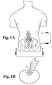
- lumbar vertebrae L3, L4 and L5 are illustrated schematically with the planned surgical site being at the L4-L5 joint through a posterion approach.
- the tubular retractor 11 according to the illustrated embodiment of the present invention is shown in place with its distal end 12 contacting the laminae of L4 and L5 at the site where the intervertebral disc 13 will be addressed.
- the oval dilator 14 is shown receiving the retractor 11.
- Tubular retractor 11 and oval dilator 14 can also be positioned at other locations along the spine and in other approaches to the spine, including lateral, postero-lateral, antero-lateral and anterior approaches.
- the METRx TM System for microdiscectomy marketed by Medtronic Sofamor Danek, USA of Memphis, Tennessee, includes a set of circular dilator tubes in diameters from 5.3mm to 16.8mm that are positioned one over the other to receive a circular retractor of desired size.
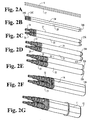
- Fig. 2A shows a couple of guide wires 16 and 17 which are vertically spaced.
- these wires are inserted through an incision in the skin at 18 and advanced through tissue to spinal bone at points 19 and 21, for wires 16 and 17, respectively, on the vertebrae. If desired, they can be advanced forcefully enough to become anchored at an appropriate spacing in a bony face or faces, depending upon the specific site to which the surgery is addressed.
- guide wires 16 and 17 could be anchored to bone and/or tissue at other locations of the posterior spine and in locations to accommodate other approaches to the spine.
- the spine has an axis in a direction from head toward feet which may be referred to hereinafter as a primary axis.
- the primary axis is designated by the line 22.
- the cross-sectional shape of the tubular retractor 11 is non-circular, and has a generally elliptical or oval shape having a major axis parallel to the axis 22 of the spine.
- the wire-to-bone contact points are on an axis or line 23 parallel to axis 22 of the spine at the surgery site.
- access can be provided to multiple vertebral elements through a single working channel.
- access to each of the vertebrae L4 and L5 can be provided through the working channel of oval tubular retractor 11 to accommodate procedures and/or implant insertion into each of the vertebrae L4 and L5 with little or no repositioning of the distal end of oval tubular retractor 11.
- each of the dilators is a circular tube with a central aperture throughout its length and sized to enable sliding the dilator along the length of the guide wire until the rounded distal end of tube 24, for example, engages a bony face or other tissue at point 19 or tissue adjacent the surgical site.
- a series of grooves 24G is provided in each tube near the proximal end such as 24P, the series extending from adjacent the proximal end toward the distal end a short distance, to facilitate grasping the tube during insertion and later when removed from the body.
- larger dilators 27 and 28 are placed on the dilators 24 and 26, respectively, and advanced along them until abutment of their distal ends, such as 27A for dilator 27, with bone or other tissue adjacent the surgical site.
- These dilators are similar to dilators 24 and 26 except for the larger size and shorter length.
- dilators 29 and 31 are placed over and advanced along dilators 27 and 28, respectively, until the distal ends 29A and 31A of these dilators contact the bone or other tissue adjacent the surgical site.
- dilators 32 and 33 are installed and advanced over the dilators 29 and 31, respectively, and advanced along until their distal ends 32A and 33A contact the bone or other tissue adjacent the surgical site.
- the soft tissue is dilated with minimal trauma.
- the set of dilators is oriented such that a plane containing the longitudinal axes of all of them, also contains the line 23 which is parallel to the spinal axis 22 and may, in some instances, be co-planar with the spinal axis 22, depending upon the direction of access desired by the surgeon.
- oval dilator 14 After insertion of the last set of the circular precursor dilators, oval dilator 14, according to the illustrated embodiment of the invention, is installed. It is advanced over the dilators 32 and 33 until the distal end 14A thereof is located where the surgeon desires, which can be in contact with the laminae of at least one of the vertebrae or adjacent other paraspinous tissue and/or other portions of the vertebral bodies. Following the seating of the oval dilator 14, the oval tubular retractor 11 according to the invention is advanced along the oval dilator 14 until its distal end 12 contacts or is proximate bone or paraspinous tissue at the surgery site.
- the precursor dilators, and guide wires if not already removed can be removed in any desired sequence or as a group, depending upon the convenience of the surgeon.
- the staggered lengths and gripping surfaces near the proximal ends thereof facilitate this.
- the oval tubular retractor 11 remains in place, providing a working channel through which viewing devices, instruments, fixation devices and materials may be passed.
- Some examples of the type of viewing systems that can be used with the tubular retractor of the present invention are those that are available with the above-mentioned METRx System, which includes microscopic viewing systems positioned over the proximal end of the retractor, and endoscopic viewing systems positioned through the retractor.
- Tubular retractor 11 could also be used with other viewing systems, such as those that include an endoscope positioned to the surgical site through a second portal and/or fluoroscopic viewing systems.
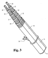
- a mounting bracket 38 is shown on the oval tubular retractor 11.
- the mounting bracket can be secured to a flexible arm or other device mounted to the surgical table or other fixture in the operating room.
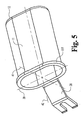
- Fig. 5 shows the tubular retractor 11 and bracket 38 and the oval internal shape of the tube and which becomes the working channel in the patient's body.
- the tube cross section is somewhat elongate with relatively straight sides and round ends. Accordingly this oval has a major axis 39, and a minor axis 41 perpendicular to the major axis.
- the axis 39 is in the same plane as line 23 (Fig. 1).
- the longitudinal axis 42 of the oval tubular retractor is intended to bisect a line between points 19 and 21 in the vertebrae, and the axis 39 lies in a plane containing the longitudinal axis 42 and parallel to a plane containing the primary spinal axis 22 at the site of the surgery, it is conceivable that the axis 39 will not be perfectly parallel to axis 22. This would be the case if it is found preferable to tip the axis 42 slightly in a vertical plane to avoid interference with and the necessity for removal of some bony structure or tissue material for access to the surgical site. It may also be desired to reposition the distal end 12 of oval retractor 11 from its initial insertion position over paraspinous tissue located outside the location of the working channel of oval retractor 11 by manipulating oval retractor 11 through the skin and tissue of the patient.
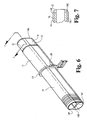
- the oval dilator 14 is shown with the oval retractor 11 slid partway between the distal end 14A and proximal end 14P of the oval dilator. Since the pair of circular cross-section dilators 32 and 33 present a grooved contour or valley at their junction and along their entire length, a volume of tissue along each side of the pair might not be entirely dilated at the time for installation of the oval dilator 14. Therefore, the oval dilator is provided with a pair of longitudinally extending internally projecting ribs 14B and 14C as shown in Fig. 6 and extending from the proximal end 14P to the distal end 14A.
- each of the ribs 14B and 14C is curved, as is the contour of the entire leading edge of the oval dilator 14, as shown in Fig. 7.
- Ribs 14B and 14C can extend into the channel of dilator 14, and facilitate alignment of oval dilator 14 along the pair of adjacent circular cross-section dilators 32 and 33.
- the externally projecting perimetrical flange 11F on the oval retractor provides a useful feature on which the bracket 38 or some other sort of bracket, if desired, can be incorporated at the point of manufacture of the retractor. Viewing instruments and/or other surgical instruments can be mounted to the oval retractor 11 on flange 11f.
- the invention can be practiced without guide wires, if desired.
- the first dilator tube is inserted and guided using fluoroscopy or other visualization technique until its distal end contacts vertebral bone or other tissue at the desired location.
- the second dilator tube is inserted, side-by-side with the first and advanced to contact of its distal end with the bone.
- a third dilator is installed on the first dilator and advanced to contact its distal end with the bone.
- a fourth dilator is installed on the second dilator and advanced to contact of its distal end with the bone. This process continues in the same manner as described above until the dilation is sufficient to accommodate the size of oval tubular retractor to be used.
- each set of dilators As each set of dilators is inserted, it can contact the wall of the adjacent dilator and provide an additional separation between the side-by-side dilators that corresponds to about one-half of the increase in the external diameter of the dilator being inserted over the external diameter of the dilator receiving the inserted dilator.
- the materials used in the guide wires, dilators and retractor can be stainless steel, aluminum, plastic, or any other material suitable for surgical instruments.
- the material can be opaque, translucent or combinations thereof.
- Specific examples of circular dilator tube diameters useful with the present invention and found in the above-mentioned publication are: 5.3 mm, 9.4 mm, 12.8 mm, 14.6 mm, and 16.8 mm, and one specific example guide wire diameter is .062 inch (1.57 mm). Other dilator and guide wire diameters are also contemplated.
- Oval tubular retractor 11 would have internal dimensions so that they slidably fit the oval dilators which slidably fit the round dilators as described above. Examples of lengths may be 3 cm to 9 cm. The length chosen will usually be the shortest that provides access to the surgical site or working space adjacent the spine, such as, for example, the vertebra lamina while allowing maximum mobility of instruments in the working channel.
- the oval retractors 11 can be provided in a set or kit of oval retractors 11 having various lengths from which the surgeon can select.
Abstract
Description
- The present invention relates to instruments for performing tissue retraction for surgeries using minimally invasive procedures.
- Traditional surgical procedures for pathologies located within the body can cause significant trauma to the intervening tissues. These procedures often require a long incision, extensive muscle stripping, prolonged retraction of tissues, denervation and devascularization of tissue. These procedures can require operating room time of several hours and several weeks of post-operative recovery time due to the destruction of tissue during the surgical procedure. In some cases, these invasive procedures lead to permanent scarring and pain that can be more severe than the pain leading to the surgical intervention.
- U.S. Patent No. 5,792,044 issued to Kevin T. Foley et al. provides rather extensive background information pertaining to percutaneous surgery. Figs. 10a through 10i of that patent depict, and column 10 at
lines 11 and following of the patent describe, steps of a method for access to a surgical site in the spine. As described, it begins with the insertion of a guide wire followed by a series of successfully larger dilators installed in sequence to dilate the soft tissues. Then, following installation of the largest dilator deemed necessary, a cannula (retractor) is advanced over the largest dilator for providing a working channel from the skin of the patient to working space adjacent the spine. The retractor can be secured in place by any of the many suitable means known in the art, several of which are mentioned in the patent. It is desirable to be able to use the working channel provided by the retractor, for surgical tools, for viewing devices and for inserting and manipulating fixation elements to the maximum extent possible for desired placement and fixation. Some such items or combinations of items dictate the inside diameter needed in the retractor. - It is sometimes desirable to have working space at the spine extending a greater distance axially of the spine than transversely. However, to provide such access through the typical circular retractors using the above-mentioned dilation techniques, could require a diameter so great as to cause significant trauma to the intervening tissues during placement of the dilators and the tubular retractor.
- The development of minimally invasive percutaneous procedures has yielded a major improvement in reducing recovery time and post-operative pain because minimal dissection of tissue (such as muscle tissue, for example) is required. Minimally invasive surgical techniques are desirable for spinal and neurosurgical applications because of the need for access to locations within the body, and the danger of damage to vital intervening tissues. While developments in minimally invasive surgery are steps in the right direction, there remains a need for further development in minimally invasive surgical instruments and methods.
- According to the present invention, there is provided a dilator and retractor set as defined by claim 1, for use in soft tissue of a human body to provide an access channel to a planned surgery site adjacent the spine.
- The preamble of claim 1 is based on US-A-6 228 022.
- One advantage of the present invention is that it provides a minimally invasive but an optimally oriented working channel for access to spinal surgery sites at the spine.
- Another advantage is provision of an improved shape of working channel.
- Another advantage is provision of a way to access greater working space adjacent the spine with minimal trauma to tissue between the skin and the spine.
- Preferred embodiments will now be described by way of example only, with reference to the drawings.
-
- Fig. 1A is a schematic drawing of a portion of the spine viewed in the back to front direction and showing an oval dilator and an oval tubular retractor according to one embodiment of the present invention, and placed at a planned surgical site.
- Fig. 1B is a schematic view along a line in a direction of arrows B-B in Fig. I A.
- Fig. 1C is a schematic view in the direction of arrows C-C in Fig. 1A.
- Fig. 2A-2G depict the series of steps and associated dilator tubes employed according to a method of use of the present invention.
- Fig. 3 is an enlarged view similar to Fig. 2G and showing a mounting bracket on the tubular retractor associated with the set of dilators.
- Fig. 4 is a view of the combination of dilators of Fig. 3 but showing them at a different angle.
- Fig. 5 is a view of the tubular retractor itself.
- Fig. 6 is a view of the tubular retractor with the oval dilator received through it but without the smaller round dilators.
- Fig. 7 is a longitudinal section of a fragment of the oval dilator taken at line 7-7 in Fig. 6 and viewed in the direction of the arrows.
- For the purposes of promoting an understanding of the principles of the invention, reference will now be made to the embodiment illustrated in the drawings and specific language will be used to describe the same. It will nevertheless be understood that the specific description is given by way of example only.
- With reference to Figs. 1A-1C, lumbar vertebrae L3, L4 and L5 are illustrated schematically with the planned surgical site being at the L4-L5 joint through a posterion approach. The
tubular retractor 11 according to the illustrated embodiment of the present invention is shown in place with itsdistal end 12 contacting the laminae of L4 and L5 at the site where theintervertebral disc 13 will be addressed. Theoval dilator 14 is shown receiving theretractor 11.Tubular retractor 11 andoval dilator 14 can also be positioned at other locations along the spine and in other approaches to the spine, including lateral, postero-lateral, antero-lateral and anterior approaches. - Current tissue dilation practice with a single guide wire and a sequence of dilators positioned over the single guide wire is shown and described in a publication entitled METRx Microdiscectomy Surgical Technique, published in 2001 by Medtronic Sofamor Danek of Memphis, Tennessee, USA.
- The METRx™ System for microdiscectomy, marketed by Medtronic Sofamor Danek, USA of Memphis, Tennessee, includes a set of circular dilator tubes in diameters from 5.3mm to 16.8mm that are positioned one over the other to receive a circular retractor of desired size.
- The present invention can be practiced with or without guide wires. An example of the present invention with guide wires will be described first. So, referring now to Figs. 2A through 2G, Fig. 2A shows a couple of
guide wires points wires guide wires - At a spinal surgery site, the spine has an axis in a direction from head toward feet which may be referred to hereinafter as a primary axis. At the site illustrated herein, the primary axis is designated by the
line 22. According to one feature of the preferred embodiment, the cross-sectional shape of thetubular retractor 11 is non-circular, and has a generally elliptical or oval shape having a major axis parallel to theaxis 22 of the spine. Accordingly, the wire-to-bone contact points (or anchor points, if desired) are on an axis orline 23 parallel toaxis 22 of the spine at the surgery site. By orienting the major axis parallel to or in the general direction ofaxis 22, access can be provided to multiple vertebral elements through a single working channel. For example, in Fig. 1C, access to each of the vertebrae L4 and L5 can be provided through the working channel of ovaltubular retractor 11 to accommodate procedures and/or implant insertion into each of the vertebrae L4 and L5 with little or no repositioning of the distal end of ovaltubular retractor 11. - Following installation of the guide wires, the first pair of
dilators wires tube 24, for example, engages a bony face or other tissue atpoint 19 or tissue adjacent the surgical site. A series of grooves 24G is provided in each tube near the proximal end such as 24P, the series extending from adjacent the proximal end toward the distal end a short distance, to facilitate grasping the tube during insertion and later when removed from the body. - Following insertion of the
dilators larger dilators dilators dilator 27, with bone or other tissue adjacent the surgical site. These dilators are similar todilators - Then dilators 29 and 31 are placed over and advanced along
dilators - Then dilators 32 and 33 are installed and advanced over the
dilators distal ends - As each of the aforementioned dilators (which may be referred to as "precursor dilators") is placed, the soft tissue is dilated with minimal trauma. Also, the set of dilators is oriented such that a plane containing the longitudinal axes of all of them, also contains the
line 23 which is parallel to thespinal axis 22 and may, in some instances, be co-planar with thespinal axis 22, depending upon the direction of access desired by the surgeon. - After insertion of the last set of the circular precursor dilators,
oval dilator 14, according to the illustrated embodiment of the invention, is installed. It is advanced over thedilators distal end 14A thereof is located where the surgeon desires, which can be in contact with the laminae of at least one of the vertebrae or adjacent other paraspinous tissue and/or other portions of the vertebral bodies. Following the seating of theoval dilator 14, the ovaltubular retractor 11 according to the invention is advanced along theoval dilator 14 until itsdistal end 12 contacts or is proximate bone or paraspinous tissue at the surgery site. - Following positioning of the oval
tubular retractor 11, the precursor dilators, and guide wires if not already removed, can be removed in any desired sequence or as a group, depending upon the convenience of the surgeon. The staggered lengths and gripping surfaces near the proximal ends thereof facilitate this. Once these dilators andoval dilator 14 have been removed, the ovaltubular retractor 11 remains in place, providing a working channel through which viewing devices, instruments, fixation devices and materials may be passed. Some examples of the type of viewing systems that can be used with the tubular retractor of the present invention are those that are available with the above-mentioned METRx System, which includes microscopic viewing systems positioned over the proximal end of the retractor, and endoscopic viewing systems positioned through the retractor.Tubular retractor 11 could also be used with other viewing systems, such as those that include an endoscope positioned to the surgical site through a second portal and/or fluoroscopic viewing systems. - Referring now to Fig. 3, the combination shown is much like that of Fig. 2G, but a mounting
bracket 38 is shown on the ovaltubular retractor 11. The mounting bracket can be secured to a flexible arm or other device mounted to the surgical table or other fixture in the operating room. - Fig. 5 shows the
tubular retractor 11 andbracket 38 and the oval internal shape of the tube and which becomes the working channel in the patient's body. In this illustrated embodiment, the tube cross section is somewhat elongate with relatively straight sides and round ends. Accordingly this oval has amajor axis 39, and aminor axis 41 perpendicular to the major axis. When this retractor is in place at the surgery site, theaxis 39 is in the same plane as line 23 (Fig. 1). - While the
longitudinal axis 42 of the oval tubular retractor is intended to bisect a line betweenpoints axis 39 lies in a plane containing thelongitudinal axis 42 and parallel to a plane containing the primaryspinal axis 22 at the site of the surgery, it is conceivable that theaxis 39 will not be perfectly parallel toaxis 22. This would be the case if it is found preferable to tip theaxis 42 slightly in a vertical plane to avoid interference with and the necessity for removal of some bony structure or tissue material for access to the surgical site. It may also be desired to reposition thedistal end 12 ofoval retractor 11 from its initial insertion position over paraspinous tissue located outside the location of the working channel ofoval retractor 11 by manipulatingoval retractor 11 through the skin and tissue of the patient. - Referring now to Fig. 6, the
oval dilator 14 is shown with theoval retractor 11 slid partway between thedistal end 14A andproximal end 14P of the oval dilator. Since the pair ofcircular cross-section dilators oval dilator 14. Therefore, the oval dilator is provided with a pair of longitudinally extending internally projectingribs proximal end 14P to thedistal end 14A. To facilitate dilation of the above mentioned volume of tissue as the oval dilator is inserted, the leading internal edge of each of theribs oval dilator 14, as shown in Fig. 7. - The thickness of the tube wall section at the
ribs lines 14L in Fig. 7.Ribs dilator 14, and facilitate alignment ofoval dilator 14 along the pair of adjacentcircular cross-section dilators - The externally projecting
perimetrical flange 11F on the oval retractor provides a useful feature on which thebracket 38 or some other sort of bracket, if desired, can be incorporated at the point of manufacture of the retractor. Viewing instruments and/or other surgical instruments can be mounted to theoval retractor 11 on flange 11f. - The invention can be practiced without guide wires, if desired. Following an incision, the first dilator tube is inserted and guided using fluoroscopy or other visualization technique until its distal end contacts vertebral bone or other tissue at the desired location. Then, through the same incision, the second dilator tube is inserted, side-by-side with the first and advanced to contact of its distal end with the bone. Then a third dilator is installed on the first dilator and advanced to contact its distal end with the bone. Then a fourth dilator is installed on the second dilator and advanced to contact of its distal end with the bone. This process continues in the same manner as described above until the dilation is sufficient to accommodate the size of oval tubular retractor to be used. As each set of dilators is inserted, it can contact the wall of the adjacent dilator and provide an additional separation between the side-by-side dilators that corresponds to about one-half of the increase in the external diameter of the dilator being inserted over the external diameter of the dilator receiving the inserted dilator.
- The materials used in the guide wires, dilators and retractor can be stainless steel, aluminum, plastic, or any other material suitable for surgical instruments. The material can be opaque, translucent or combinations thereof. Specific examples of circular dilator tube diameters useful with the present invention and found in the above-mentioned publication are: 5.3 mm, 9.4 mm, 12.8 mm, 14.6 mm, and 16.8 mm, and one specific example guide wire diameter is .062 inch (1.57 mm). Other dilator and guide wire diameters are also contemplated.
- One example of dimensions of the major and minor axes of the oval
tubular dilator 14 of the present invention may be 40 mm and 20 mm, respectively. A smaller one may be 28 mm and 14 mm, respectively. Other sizes may be provided if desired. Ovaltubular retractor 11 would have internal dimensions so that they slidably fit the oval dilators which slidably fit the round dilators as described above. Examples of lengths may be 3 cm to 9 cm. The length chosen will usually be the shortest that provides access to the surgical site or working space adjacent the spine, such as, for example, the vertebra lamina while allowing maximum mobility of instruments in the working channel. Theoval retractors 11 can be provided in a set or kit ofoval retractors 11 having various lengths from which the surgeon can select.
Claims (9)
- A dilator and a retractor set for use in soft tissue of a human body to provide an access channel to a planned surgery site adjacent the spine and comprising:a dilator tube (14) having a proximal end and a distal end and a longitudinal axis;said tube having a non-circular cross-sectional shape in a plane perpendicular to said longitudinal axis at a first location proximate said distal end; wherein said dilator tube has a channel therethrough and an exterior surface defining said non-circular cross-sectional shape, characterized by said dilator and retractor set further comprising a pair of side-by-side dilators (24, 26; 27, 28; 29, 31; 32, 33) adapted to be received in said channel, and each having a circular cross-section transverse to a longitudinal axis thereof; and a retractor (11) arranged over said dilator tube (16), and having a working channel with a cross-sectional shape corresponding to said cross-sectional shape of said exterior surface.
- The dilator and retractor set of claim 1 and wherein:said tube has non-circular cross-sectional shape in planes perpendicular to said longitudinal axis, said shape extending from said first location proximate said distal end to a second location at least eighty percent of the distance from said distal end to said proximal end.
- The dilator and retractor set of claim 2 and wherein:said tube has non-circular cross-sectional shape throughout its length from said distal end to said proximal end.
- The dilator and retractor set of claim 2 and wherein:the shape of said non-circular cross-sectional shape of said tube is the same from said first location to said second location and has a major axis and a minor axis.
- The dilator and retractor set of claim 4 and wherein:the overall dimension of said dilator along the major axis is between 28 and 40 mm; andthe overall dimension of said dilator along the minor axis is between 14 and 20 mm.
- The dilator and retractor set of claim 4 and wherein:said shape is elongate with parallel sides and circular ends with radii, the centers of the end radii being on a line bisecting the minor axis.
- The dilator and retractor set of claim 6 and wherein:said tube has perimetrical external ribs longitudinally-spaced in a series extending from said proximal end toward said distal end.
- The dilator and retractor set of any preceding claim, further comprising
a first set of telescoped tissue-dilator tubes (24, 27, 29, 32) coaxial with a first axis;
a second set of telescoped tissue-dilator tubes (26, 28, 31, 33) coaxial with a second axis; and wherein
said tube (14) encompasses said first and second sets of dilator tubes and is slidably received on said first and second sets. - The dilator and retractor set of claim 1, further comprising at least one set of telescoped tissue-dilator tubes having a circular cross-section in said plane and slidably received in said channel, wherein said at least one set includes a pair of side-by-side telescoped tissue-dilator sets each having circular cross-sections in said plane and slidably received in said channel.
Applications Claiming Priority (3)
| Application Number | Priority Date | Filing Date | Title |
|---|---|---|---|
| US246995 | 2002-09-19 | ||
| US10/246,995 US7074226B2 (en) | 2002-09-19 | 2002-09-19 | Oval dilator and retractor set and method |
| PCT/US2003/029156 WO2004028382A2 (en) | 2002-09-19 | 2003-09-16 | Oval dilator and retractor set and method |
Publications (2)
| Publication Number | Publication Date |
|---|---|
| EP1542595A2 EP1542595A2 (en) | 2005-06-22 |
| EP1542595B1 true EP1542595B1 (en) | 2006-12-06 |
Family
ID=31992411
Family Applications (1)
| Application Number | Title | Priority Date | Filing Date |
|---|---|---|---|
| EP03796334A Expired - Lifetime EP1542595B1 (en) | 2002-09-19 | 2003-09-16 | Oval dilator and retractor set |
Country Status (10)
| Country | Link |
|---|---|
| US (2) | US7074226B2 (en) |
| EP (1) | EP1542595B1 (en) |
| JP (1) | JP4397812B2 (en) |
| KR (1) | KR20050052504A (en) |
| CN (1) | CN100345519C (en) |
| AT (1) | ATE347313T1 (en) |
| AU (1) | AU2003298584A1 (en) |
| CA (1) | CA2499248A1 (en) |
| DE (1) | DE60310241T2 (en) |
| WO (1) | WO2004028382A2 (en) |
Cited By (1)
| Publication number | Priority date | Publication date | Assignee | Title |
|---|---|---|---|---|
| TWI450228B (en) * | 2010-01-15 | 2014-08-21 | 私立中原大學 | A method of simulating spinal surgery on a computer system |
Families Citing this family (169)
| Publication number | Priority date | Publication date | Assignee | Title |
|---|---|---|---|---|
| US7799036B2 (en) * | 1998-08-20 | 2010-09-21 | Zimmer Spine, Inc. | Method and apparatus for securing vertebrae |
| US6187000B1 (en) * | 1998-08-20 | 2001-02-13 | Endius Incorporated | Cannula for receiving surgical instruments |
| US7056321B2 (en) * | 2000-08-01 | 2006-06-06 | Endius, Incorporated | Method of securing vertebrae |
| US7985247B2 (en) | 2000-08-01 | 2011-07-26 | Zimmer Spine, Inc. | Methods and apparatuses for treating the spine through an access device |
| JP4125234B2 (en) * | 2001-11-01 | 2008-07-30 | スパイン・ウェイブ・インコーポレーテッド | Apparatus and method for pretreatment of endplates between discs |
| AU2002336694A1 (en) * | 2001-11-01 | 2003-05-12 | Lawrence M. Boyd | Devices and methods for the restoration of a spinal disc |
| DE10154163A1 (en) | 2001-11-03 | 2003-05-22 | Advanced Med Tech | Device for straightening and stabilizing the spine |
| US7004947B2 (en) | 2002-06-24 | 2006-02-28 | Endius Incorporated | Surgical instrument for moving vertebrae |
| US7582058B1 (en) | 2002-06-26 | 2009-09-01 | Nuvasive, Inc. | Surgical access system and related methods |
| US6793678B2 (en) | 2002-06-27 | 2004-09-21 | Depuy Acromed, Inc. | Prosthetic intervertebral motion disc having dampening |
| US6648888B1 (en) | 2002-09-06 | 2003-11-18 | Endius Incorporated | Surgical instrument for moving a vertebra |
| US7320686B2 (en) * | 2002-10-09 | 2008-01-22 | Depuy Acromed, Inc. | Device for distracting vertebrae and delivering a flowable material into a disc space |
| AU2003272308A1 (en) * | 2002-10-25 | 2004-05-25 | Endius Incorporated | Apparatus and methods for shielding body structures during surgery |
| ES2440284T3 (en) * | 2002-11-14 | 2014-01-28 | Thermo Fisher Scientific Biosciences Inc. | SiRNA directed to tp53 |
| US20060155170A1 (en) * | 2002-12-13 | 2006-07-13 | Synthes Spine Company, Lp | Guided retractor and methods of use |
| US20040116777A1 (en) * | 2002-12-13 | 2004-06-17 | Jeffrey Larson | Guided retractor and methods of use |
| US7014608B2 (en) * | 2002-12-13 | 2006-03-21 | Synthes Spine Company, Lp | Guided retractor and methods of use |
| AU2004212942A1 (en) | 2003-02-14 | 2004-09-02 | Depuy Spine, Inc. | In-situ formed intervertebral fusion device |
| US7641659B2 (en) * | 2003-03-13 | 2010-01-05 | Zimmer Spine, Inc. | Spinal access instrument |
| US7645232B2 (en) * | 2003-05-16 | 2010-01-12 | Zimmer Spine, Inc. | Access device for minimally invasive surgery |
| US7811303B2 (en) * | 2003-08-26 | 2010-10-12 | Medicine Lodge Inc | Bodily tissue dilation systems and methods |
| US7955355B2 (en) | 2003-09-24 | 2011-06-07 | Stryker Spine | Methods and devices for improving percutaneous access in minimally invasive surgeries |
| US8002798B2 (en) | 2003-09-24 | 2011-08-23 | Stryker Spine | System and method for spinal implant placement |
| US7655012B2 (en) * | 2003-10-02 | 2010-02-02 | Zimmer Spine, Inc. | Methods and apparatuses for minimally invasive replacement of intervertebral discs |
| EP1691848B1 (en) * | 2003-10-23 | 2012-08-22 | TRANS1, Inc. | Tools and tool kits for performing minimally invasive procedures on the spine |
| US7144368B2 (en) * | 2003-11-26 | 2006-12-05 | Synthes Spine Company, Lp | Guided retractor and methods of use |
| EP2332468B1 (en) | 2003-12-18 | 2016-11-09 | DePuy Spine, Inc. | Surgical retractor systems |
| WO2005070071A2 (en) | 2004-01-08 | 2005-08-04 | Spine Wave Inc. | Apparatus and method for injecting fluent material at a distracted tissue site |
| EP1768617A4 (en) | 2004-06-29 | 2011-08-10 | Spine Wave Inc | Methods for treating defects and injuries of an intervertebral disc |
| US20060004398A1 (en) * | 2004-07-02 | 2006-01-05 | Binder Lawrence J Jr | Sequential dilator system |
| US9387313B2 (en) | 2004-08-03 | 2016-07-12 | Interventional Spine, Inc. | Telescopic percutaneous tissue dilation systems and related methods |
| US20060030872A1 (en) * | 2004-08-03 | 2006-02-09 | Brad Culbert | Dilation introducer for orthopedic surgery |
| US20060052812A1 (en) * | 2004-09-07 | 2006-03-09 | Michael Winer | Tool for preparing a surgical site for an access device |
| US7666189B2 (en) * | 2004-09-29 | 2010-02-23 | Synthes Usa, Llc | Less invasive surgical system and methods |
| CA2614133A1 (en) * | 2004-10-25 | 2006-05-04 | Lanx, Llc | Interspinous distraction devices and associated methods of insertion |
| US8241330B2 (en) | 2007-01-11 | 2012-08-14 | Lanx, Inc. | Spinous process implants and associated methods |
| US9055981B2 (en) | 2004-10-25 | 2015-06-16 | Lanx, Inc. | Spinal implants and methods |
| WO2006047652A2 (en) | 2004-10-26 | 2006-05-04 | Concept Matrix, Llc | Working channel for minimally invasive spine surgery |
| EP1871245A4 (en) * | 2005-04-05 | 2010-10-27 | Interventional Spine Inc | Tissue dilation systems and related methods |
| US9314273B2 (en) | 2005-04-27 | 2016-04-19 | Globus Medical, Inc. | Percutaneous vertebral stabilization system |
| US7758617B2 (en) * | 2005-04-27 | 2010-07-20 | Globus Medical, Inc. | Percutaneous vertebral stabilization system |
| US20060271055A1 (en) * | 2005-05-12 | 2006-11-30 | Jeffery Thramann | Spinal stabilization |
| US20060271048A1 (en) * | 2005-05-12 | 2006-11-30 | Jeffery Thramann | Pedicle screw based vertebral body stabilization apparatus |
| US7828830B2 (en) | 2005-05-12 | 2010-11-09 | Lanx, Inc. | Dynamic spinal stabilization |
| US20070032703A1 (en) * | 2005-07-11 | 2007-02-08 | Sankaran Meera L | Radially expansive surgical instruments for tissue retraction and methods for using the same |
| US7566302B2 (en) * | 2005-07-28 | 2009-07-28 | Synthes Usa, Llc | Expandable access device |
| US7670375B2 (en) | 2005-08-16 | 2010-03-02 | Benvenue Medical, Inc. | Methods for limiting the movement of material introduced between layers of spinal tissue |
| US8366773B2 (en) | 2005-08-16 | 2013-02-05 | Benvenue Medical, Inc. | Apparatus and method for treating bone |
| US8480576B2 (en) * | 2005-12-07 | 2013-07-09 | Faheem A. Sandhu | Access system for minimally invasive spinal surgery |
| US7981031B2 (en) | 2006-01-04 | 2011-07-19 | Depuy Spine, Inc. | Surgical access devices and methods of minimally invasive surgery |
| US7918792B2 (en) | 2006-01-04 | 2011-04-05 | Depuy Spine, Inc. | Surgical retractor for use with minimally invasive spinal stabilization systems and methods of minimally invasive surgery |
| US7758501B2 (en) | 2006-01-04 | 2010-07-20 | Depuy Spine, Inc. | Surgical reactors and methods of minimally invasive surgery |
| US7955257B2 (en) | 2006-01-05 | 2011-06-07 | Depuy Spine, Inc. | Non-rigid surgical retractor |
| CA2637684C (en) | 2006-02-06 | 2011-09-13 | Stryker Spine | Rod contouring apparatus and method for percutaneous pedicle screw extension |
| US8834527B2 (en) * | 2006-06-16 | 2014-09-16 | Alphatec Spine, Inc. | Systems and methods for manipulating and/or installing a pedicle screw |
| US8357168B2 (en) * | 2006-09-08 | 2013-01-22 | Spine Wave, Inc. | Modular injection needle and seal assembly |
| US7749226B2 (en) * | 2006-09-22 | 2010-07-06 | Biomet Sports Medicine, Llc | Method for forming a tunnel in a bone |
| US8840621B2 (en) | 2006-11-03 | 2014-09-23 | Innovative Spine, Inc. | Spinal access systems and methods |
| US8025664B2 (en) * | 2006-11-03 | 2011-09-27 | Innovative Spine, Llc | System and method for providing surgical access to a spine |
| US8740941B2 (en) | 2006-11-10 | 2014-06-03 | Lanx, Inc. | Pedicle based spinal stabilization with adjacent vertebral body support |
| US8105382B2 (en) | 2006-12-07 | 2012-01-31 | Interventional Spine, Inc. | Intervertebral implant |
| US8979931B2 (en) | 2006-12-08 | 2015-03-17 | DePuy Synthes Products, LLC | Nucleus replacement device and method |
| US7850714B2 (en) * | 2006-12-15 | 2010-12-14 | Kimberly-Clark Worldwide, Inc. | Segmented tissue-to-tissue anchoring device and method of using the same |
| US9265532B2 (en) | 2007-01-11 | 2016-02-23 | Lanx, Inc. | Interspinous implants and methods |
| US8062217B2 (en) | 2007-01-26 | 2011-11-22 | Theken Spine, Llc | Surgical retractor with removable blades and method of use |
| JP5271281B2 (en) * | 2007-02-09 | 2013-08-21 | アルファテック スパイン, インコーポレイテッド | Curved spine access method and device |
| EP2124777A4 (en) | 2007-02-21 | 2013-06-05 | Benvenue Medical Inc | Devices for treating the spine |
| CA2678006C (en) | 2007-02-21 | 2014-10-14 | Benvenue Medical, Inc. | Devices for treating the spine |
| US8202216B2 (en) * | 2007-03-08 | 2012-06-19 | Warsaw Orthopedic, Inc. | Tissue retractor |
| US8900307B2 (en) | 2007-06-26 | 2014-12-02 | DePuy Synthes Products, LLC | Highly lordosed fusion cage |
| US20090062690A1 (en) * | 2007-08-29 | 2009-03-05 | Quaternion Investments Llc | Specimen Collecting |
| CA2701504A1 (en) | 2007-10-05 | 2009-04-09 | Synthes Usa, Llc | Dilation system and method of using the same |
| EP2471493A1 (en) | 2008-01-17 | 2012-07-04 | Synthes GmbH | An expandable intervertebral implant and associated method of manufacturing the same |
| BRPI0910325A8 (en) | 2008-04-05 | 2019-01-29 | Synthes Gmbh | expandable intervertebral implant |
| US8876851B1 (en) | 2008-10-15 | 2014-11-04 | Nuvasive, Inc. | Systems and methods for performing spinal fusion surgery |
| US20100114147A1 (en) * | 2008-10-30 | 2010-05-06 | The University Of Toledo | Directional soft tissue dilator and docking pin with integrated light source for optimization of retractor placement in minimally invasive spine surgery |
| US8535327B2 (en) | 2009-03-17 | 2013-09-17 | Benvenue Medical, Inc. | Delivery apparatus for use with implantable medical devices |
| US9526620B2 (en) | 2009-03-30 | 2016-12-27 | DePuy Synthes Products, Inc. | Zero profile spinal fusion cage |
| MX2011010375A (en) | 2009-03-31 | 2012-02-23 | Lanx Inc | Spinous process implants and associated methods. |
| US8152720B2 (en) * | 2009-08-05 | 2012-04-10 | Thomas Stuart Loftus | Retracto component system and method of using same |
| WO2011050140A1 (en) | 2009-10-22 | 2011-04-28 | Blue Fury Consulting, L.L.C. | Posterior cervical fusion system and techniques |
| US10098674B2 (en) | 2009-10-22 | 2018-10-16 | Nuvasive, Inc. | System and method for posterior cervical fusion |
| US9393129B2 (en) | 2009-12-10 | 2016-07-19 | DePuy Synthes Products, Inc. | Bellows-like expandable interbody fusion cage |
| US8979860B2 (en) | 2010-06-24 | 2015-03-17 | DePuy Synthes Products. LLC | Enhanced cage insertion device |
| US9282979B2 (en) | 2010-06-24 | 2016-03-15 | DePuy Synthes Products, Inc. | Instruments and methods for non-parallel disc space preparation |
| EP2588034B1 (en) | 2010-06-29 | 2018-01-03 | Synthes GmbH | Distractible intervertebral implant |
| US8617062B2 (en) | 2010-07-08 | 2013-12-31 | Warsaw Orthopedic, Inc. | Over dilation |
| WO2012040206A1 (en) | 2010-09-20 | 2012-03-29 | Synthes Usa, Llc | Spinal access retractor |
| US9402732B2 (en) | 2010-10-11 | 2016-08-02 | DePuy Synthes Products, Inc. | Expandable interspinous process spacer implant |
| GB2485762B (en) | 2010-11-12 | 2012-12-05 | Cook Medical Technologies Llc | Introducer assembly and dilator tip therefor |
| US8518087B2 (en) | 2011-03-10 | 2013-08-27 | Interventional Spine, Inc. | Method and apparatus for minimally invasive insertion of intervertebral implants |
| US8394129B2 (en) | 2011-03-10 | 2013-03-12 | Interventional Spine, Inc. | Method and apparatus for minimally invasive insertion of intervertebral implants |
| US8834507B2 (en) | 2011-05-17 | 2014-09-16 | Warsaw Orthopedic, Inc. | Dilation instruments and methods |
| US8834508B2 (en) | 2011-05-27 | 2014-09-16 | Spinefrontier Inc | Methods, tools and devices for percutaneous access in minimally invasive spinal surgeries |
| US8814873B2 (en) | 2011-06-24 | 2014-08-26 | Benvenue Medical, Inc. | Devices and methods for treating bone tissue |
| US11812923B2 (en) | 2011-10-07 | 2023-11-14 | Alan Villavicencio | Spinal fixation device |
| US9622779B2 (en) | 2011-10-27 | 2017-04-18 | DePuy Synthes Products, Inc. | Method and devices for a sub-splenius / supra-levator scapulae surgical access technique |
| WO2013067179A2 (en) | 2011-11-01 | 2013-05-10 | Synthes Usa, Llc | Dilation system |
| US9060815B1 (en) | 2012-03-08 | 2015-06-23 | Nuvasive, Inc. | Systems and methods for performing spine surgery |
| US9888859B1 (en) | 2013-03-14 | 2018-02-13 | Nuvasive, Inc. | Directional dilator for intraoperative monitoring |
| US9265490B2 (en) | 2012-04-16 | 2016-02-23 | DePuy Synthes Products, Inc. | Detachable dilator blade |
| US8940052B2 (en) | 2012-07-26 | 2015-01-27 | DePuy Synthes Products, LLC | Expandable implant |
| US20140067069A1 (en) | 2012-08-30 | 2014-03-06 | Interventional Spine, Inc. | Artificial disc |
| US9480855B2 (en) | 2012-09-26 | 2016-11-01 | DePuy Synthes Products, Inc. | NIR/red light for lateral neuroprotection |
| US9084591B2 (en) | 2012-10-23 | 2015-07-21 | Neurostructures, Inc. | Retractor |
| US9522070B2 (en) | 2013-03-07 | 2016-12-20 | Interventional Spine, Inc. | Intervertebral implant |
| US9277928B2 (en) | 2013-03-11 | 2016-03-08 | Interventional Spine, Inc. | Method and apparatus for minimally invasive insertion of intervertebral implants |
| CA2846149C (en) | 2013-03-14 | 2018-03-20 | Stryker Spine | Systems and methods for percutaneous spinal fusion |
| US9572676B2 (en) | 2013-03-14 | 2017-02-21 | DePuy Synthes Products, Inc. | Adjustable multi-volume balloon for spinal interventions |
| US9993353B2 (en) | 2013-03-14 | 2018-06-12 | DePuy Synthes Products, Inc. | Method and apparatus for minimally invasive insertion of intervertebral implants |
| US9827020B2 (en) | 2013-03-14 | 2017-11-28 | Stryker European Holdings I, Llc | Percutaneous spinal cross link system and method |
| US9913728B2 (en) | 2013-03-14 | 2018-03-13 | Quandary Medical, Llc | Spinal implants and implantation system |
| US9585761B2 (en) | 2013-03-14 | 2017-03-07 | DePuy Synthes Products, Inc. | Angulated rings and bonded foils for use with balloons for fusion and dynamic stabilization |
| US9358120B2 (en) | 2013-03-14 | 2016-06-07 | DePuy Synthes Products, Inc. | Expandable coil spinal implant |
| US10085783B2 (en) | 2013-03-14 | 2018-10-02 | Izi Medical Products, Llc | Devices and methods for treating bone tissue |
| AU2014257302B2 (en) * | 2013-04-24 | 2019-04-18 | Medovex, LLC | Minimally invasive methods for spinal facet therapy to alleviate pain and associated surgical tools, kits and instructional media |
| US10159579B1 (en) | 2013-12-06 | 2018-12-25 | Stryker European Holdings I, Llc | Tubular instruments for percutaneous posterior spinal fusion systems and methods |
| US9408716B1 (en) | 2013-12-06 | 2016-08-09 | Stryker European Holdings I, Llc | Percutaneous posterior spinal fusion implant construction and method |
| US9744050B1 (en) | 2013-12-06 | 2017-08-29 | Stryker European Holdings I, Llc | Compression and distraction system for percutaneous posterior spinal fusion |
| US9339263B2 (en) * | 2014-01-03 | 2016-05-17 | DePuy Synthes Products, Inc. | Dilation system and method |
| US9724137B2 (en) | 2014-03-19 | 2017-08-08 | Warsaw Orthopedic, Inc. | Surgical instrumentation and method |
| US9549723B2 (en) | 2014-03-19 | 2017-01-24 | Warsaw Othropedic, Inc. | Surgical instrumentation and method |
| US20150351737A1 (en) * | 2014-06-05 | 2015-12-10 | Jeffrey Jackson | Multi-chambered cannula |
| US10398494B2 (en) | 2014-07-30 | 2019-09-03 | Medovex Corp. | Surgical tools for spinal facet therapy to alleviate pain and related methods |
| US9980737B2 (en) | 2014-08-04 | 2018-05-29 | Medos International Sarl | Flexible transport auger |
| US10258228B2 (en) * | 2014-08-08 | 2019-04-16 | K2M, Inc. | Retraction devices, systems, and methods for minimally invasive spinal surgery |
| US10264959B2 (en) | 2014-09-09 | 2019-04-23 | Medos International Sarl | Proximal-end securement of a minimally invasive working channel |
| US9924979B2 (en) | 2014-09-09 | 2018-03-27 | Medos International Sarl | Proximal-end securement of a minimally invasive working channel |
| US10111712B2 (en) | 2014-09-09 | 2018-10-30 | Medos International Sarl | Proximal-end securement of a minimally invasive working channel |
| US10034690B2 (en) | 2014-12-09 | 2018-07-31 | John A. Heflin | Spine alignment system |
| US9808598B2 (en) | 2015-02-04 | 2017-11-07 | Teleflex Medical Incorporated | Flexible tip dilator |
| US11426290B2 (en) | 2015-03-06 | 2022-08-30 | DePuy Synthes Products, Inc. | Expandable intervertebral implant, system, kit and method |
| US10786264B2 (en) | 2015-03-31 | 2020-09-29 | Medos International Sarl | Percutaneous disc clearing device |
| JP6843759B2 (en) | 2015-03-31 | 2021-03-17 | フィッシャー アンド ペイケル ヘルスケア リミテッド | User interface and system for supplying gas to the airways |
| JP2018517507A (en) | 2015-06-11 | 2018-07-05 | ハウメディカ・オステオニクス・コーポレイション | Spinal fixation targeting system and method for posterior spine surgery |
| US9913727B2 (en) | 2015-07-02 | 2018-03-13 | Medos International Sarl | Expandable implant |
| CN113143355A (en) | 2015-09-04 | 2021-07-23 | 美多斯国际有限公司 | Multi-shield spinal access system |
| US11439380B2 (en) | 2015-09-04 | 2022-09-13 | Medos International Sarl | Surgical instrument connectors and related methods |
| US11744447B2 (en) | 2015-09-04 | 2023-09-05 | Medos International | Surgical visualization systems and related methods |
| US10987129B2 (en) | 2015-09-04 | 2021-04-27 | Medos International Sarl | Multi-shield spinal access system |
| US11672562B2 (en) | 2015-09-04 | 2023-06-13 | Medos International Sarl | Multi-shield spinal access system |
| US10925592B2 (en) * | 2016-01-19 | 2021-02-23 | K2M, Inc. | Tissue dilation system and methods of use |
| US10299838B2 (en) | 2016-02-05 | 2019-05-28 | Medos International Sarl | Method and instruments for interbody fusion and posterior fixation through a single incision |
| US11510788B2 (en) | 2016-06-28 | 2022-11-29 | Eit Emerging Implant Technologies Gmbh | Expandable, angularly adjustable intervertebral cages |
| US11596522B2 (en) | 2016-06-28 | 2023-03-07 | Eit Emerging Implant Technologies Gmbh | Expandable and angularly adjustable intervertebral cages with articulating joint |
| GB2567998B (en) | 2016-08-11 | 2022-07-20 | Fisher & Paykel Healthcare Ltd | A collapsible conduit, patient interface and headgear connector |
| US10537436B2 (en) | 2016-11-01 | 2020-01-21 | DePuy Synthes Products, Inc. | Curved expandable cage |
| US10888433B2 (en) | 2016-12-14 | 2021-01-12 | DePuy Synthes Products, Inc. | Intervertebral implant inserter and related methods |
| US10398563B2 (en) | 2017-05-08 | 2019-09-03 | Medos International Sarl | Expandable cage |
| CN107361801A (en) * | 2017-05-16 | 2017-11-21 | 李茂雷 | Nerve endoscope passage |
| US11344424B2 (en) | 2017-06-14 | 2022-05-31 | Medos International Sarl | Expandable intervertebral implant and related methods |
| US10940016B2 (en) | 2017-07-05 | 2021-03-09 | Medos International Sarl | Expandable intervertebral fusion cage |
| US20190275307A1 (en) * | 2018-03-06 | 2019-09-12 | Alpine Medical Devices, Llc | Method of using an endoscopic dilator |
| US11446156B2 (en) | 2018-10-25 | 2022-09-20 | Medos International Sarl | Expandable intervertebral implant, inserter instrument, and related methods |
| CN109512476B (en) * | 2018-12-19 | 2020-08-28 | 四川大学华西医院 | Intraoperative traction device for early cancers of digestive tract |
| US10959716B2 (en) | 2019-02-11 | 2021-03-30 | Warsaw Orthopedic, Inc. | Surgical retractor system and method |
| US11266391B2 (en) | 2019-02-11 | 2022-03-08 | Warsaw Orthopedic, Inc. | Surgical retractor and method |
| US11013530B2 (en) | 2019-03-08 | 2021-05-25 | Medos International Sarl | Surface features for device retention |
| US11241252B2 (en) | 2019-03-22 | 2022-02-08 | Medos International Sarl | Skin foundation access portal |
| US11129727B2 (en) | 2019-03-29 | 2021-09-28 | Medos International Sari | Inflatable non-distracting intervertebral implants and related methods |
| US11813026B2 (en) | 2019-04-05 | 2023-11-14 | Medos International Sarl | Systems, devices, and methods for providing surgical trajectory guidance |
| KR102276071B1 (en) * | 2019-06-13 | 2021-07-13 | 주식회사 솔고바이오메디칼 | Retractor for spinal surgery |
| RU2720709C1 (en) * | 2019-08-20 | 2020-05-12 | федеральное государственное бюджетное образовательное учреждение высшего образования "Приволжский исследовательский медицинский университет" Министерства здравоохранения Российской Федерации (ФГБОУ ВО "ПИМУ" Минздрава России) | Method of accessing structures of different spinal regions and a device for its implementation |
| US11426286B2 (en) | 2020-03-06 | 2022-08-30 | Eit Emerging Implant Technologies Gmbh | Expandable intervertebral implant |
| CN111449730B (en) * | 2020-04-03 | 2021-03-19 | 吉林大学 | Safe puncture channel expanding device for intravascular interventional therapy |
| KR102486623B1 (en) * | 2020-10-15 | 2023-01-09 | 가톨릭대학교 산학협력단 | Non-circular dilator unit for minimally invasive spinal surgery |
| US11771517B2 (en) | 2021-03-12 | 2023-10-03 | Medos International Sarl | Camera position indication systems and methods |
| US11850160B2 (en) | 2021-03-26 | 2023-12-26 | Medos International Sarl | Expandable lordotic intervertebral fusion cage |
| US11752009B2 (en) | 2021-04-06 | 2023-09-12 | Medos International Sarl | Expandable intervertebral fusion cage |
Citations (1)
| Publication number | Priority date | Publication date | Assignee | Title |
|---|---|---|---|---|
| EP0935974A1 (en) * | 1998-02-11 | 1999-08-18 | Porges | Telescopic device to dilate a body vessel |
Family Cites Families (29)
| Publication number | Priority date | Publication date | Assignee | Title |
|---|---|---|---|---|
| US672377A (en) * | 1900-03-27 | 1901-04-16 | William D Kearns | Dilator. |
| US1719428A (en) * | 1927-05-21 | 1929-07-02 | Friedman William | Syringe |
| USRE32158E (en) * | 1980-07-30 | 1986-05-27 | Arthroscope | |
| US4545374A (en) * | 1982-09-03 | 1985-10-08 | Jacobson Robert E | Method and instruments for performing a percutaneous lumbar diskectomy |
| CN1128944A (en) * | 1988-06-13 | 1996-08-14 | 卡林技术公司 | Apparatus and method of inserting spinal implants |
| US5484437A (en) * | 1988-06-13 | 1996-01-16 | Michelson; Gary K. | Apparatus and method of inserting spinal implants |
| US5176128A (en) * | 1991-01-24 | 1993-01-05 | Andrese Craig A | Organ retractor |
| US5199419A (en) * | 1991-08-05 | 1993-04-06 | United States Surgical Corporation | Surgical retractor |
| US5269797A (en) * | 1991-09-12 | 1993-12-14 | Meditron Devices, Inc. | Cervical discectomy instruments |
| US5762629A (en) * | 1991-10-30 | 1998-06-09 | Smith & Nephew, Inc. | Oval cannula assembly and method of use |
| US5439467A (en) * | 1991-12-03 | 1995-08-08 | Vesica Medical, Inc. | Suture passer |
| US5269772A (en) * | 1992-01-24 | 1993-12-14 | Wilk Peter J | Laparoscopic cannula assembly and associated method |
| US5569205A (en) * | 1994-07-14 | 1996-10-29 | Hart; Charles C. | Multiport trocar |
| US5868758A (en) * | 1995-02-28 | 1999-02-09 | Markman; Barry S. | Method apparatus and kit for performing hair grafts |
| FR2742652B1 (en) | 1995-12-21 | 1998-02-27 | Colorado | INTERVERTEBRAL IMPLANT, INTERSOMATIC CAGE TYPE |
| US5792044A (en) * | 1996-03-22 | 1998-08-11 | Danek Medical, Inc. | Devices and methods for percutaneous surgery |
| TW375522B (en) * | 1996-10-24 | 1999-12-01 | Danek Medical Inc | Devices for percutaneous surgery under direct visualization and through an elongated cannula |
| US5976146A (en) * | 1997-07-11 | 1999-11-02 | Olympus Optical Co., Ltd. | Surgical operation system and method of securing working space for surgical operation in body |
| US6004326A (en) * | 1997-09-10 | 1999-12-21 | United States Surgical | Method and instrumentation for implant insertion |
| EP1069864B1 (en) | 1998-04-09 | 2004-09-01 | SDGI Holdings, Inc. | Vertebral body distraction device |
| DE29814174U1 (en) * | 1998-08-07 | 1999-12-16 | Howmedica Gmbh | Instruments for inserting an implant into the human spine |
| US6228022B1 (en) * | 1998-10-28 | 2001-05-08 | Sdgi Holdings, Inc. | Methods and instruments for spinal surgery |
| JP4243026B2 (en) * | 1999-02-04 | 2009-03-25 | ウォーソー・オーソペディック・インコーポレーテッド | Surgical instruments |
| US6648895B2 (en) * | 2000-02-04 | 2003-11-18 | Sdgi Holdings, Inc. | Methods and instrumentation for vertebral interbody fusion |
| US6383191B1 (en) * | 2000-03-15 | 2002-05-07 | Sdgi Holdings, Inc. | Laparoscopic instrument sleeve |
| US7702541B2 (en) * | 2000-08-01 | 2010-04-20 | Yahoo! Inc. | Targeted e-commerce system |
| US6551270B1 (en) * | 2000-08-30 | 2003-04-22 | Snowden Pencer, Inc. | Dual lumen access port |
| US6916330B2 (en) * | 2001-10-30 | 2005-07-12 | Depuy Spine, Inc. | Non cannulated dilators |
| US7008431B2 (en) * | 2001-10-30 | 2006-03-07 | Depuy Spine, Inc. | Configured and sized cannula |
-
2002
- 2002-09-19 US US10/246,995 patent/US7074226B2/en not_active Expired - Fee Related
-
2003
- 2003-09-16 EP EP03796334A patent/EP1542595B1/en not_active Expired - Lifetime
- 2003-09-16 AU AU2003298584A patent/AU2003298584A1/en not_active Abandoned
- 2003-09-16 DE DE60310241T patent/DE60310241T2/en not_active Expired - Fee Related
- 2003-09-16 AT AT03796334T patent/ATE347313T1/en not_active IP Right Cessation
- 2003-09-16 CN CNB038243717A patent/CN100345519C/en not_active Expired - Fee Related
- 2003-09-16 WO PCT/US2003/029156 patent/WO2004028382A2/en active IP Right Grant
- 2003-09-16 KR KR1020057004581A patent/KR20050052504A/en not_active Application Discontinuation
- 2003-09-16 JP JP2004540093A patent/JP4397812B2/en not_active Expired - Fee Related
- 2003-09-16 CA CA002499248A patent/CA2499248A1/en not_active Abandoned
-
2006
- 2006-06-29 US US11/478,041 patent/US7618431B2/en not_active Expired - Fee Related
Patent Citations (1)
| Publication number | Priority date | Publication date | Assignee | Title |
|---|---|---|---|---|
| EP0935974A1 (en) * | 1998-02-11 | 1999-08-18 | Porges | Telescopic device to dilate a body vessel |
Cited By (1)
| Publication number | Priority date | Publication date | Assignee | Title |
|---|---|---|---|---|
| TWI450228B (en) * | 2010-01-15 | 2014-08-21 | 私立中原大學 | A method of simulating spinal surgery on a computer system |
Also Published As
| Publication number | Publication date |
|---|---|
| WO2004028382A3 (en) | 2004-10-07 |
| CN1688257A (en) | 2005-10-26 |
| CN100345519C (en) | 2007-10-31 |
| KR20050052504A (en) | 2005-06-02 |
| CA2499248A1 (en) | 2004-04-08 |
| JP2006500168A (en) | 2006-01-05 |
| AU2003298584A1 (en) | 2004-04-19 |
| JP4397812B2 (en) | 2010-01-13 |
| US20060247651A1 (en) | 2006-11-02 |
| ATE347313T1 (en) | 2006-12-15 |
| US20040059339A1 (en) | 2004-03-25 |
| EP1542595A2 (en) | 2005-06-22 |
| WO2004028382A2 (en) | 2004-04-08 |
| DE60310241D1 (en) | 2007-01-18 |
| US7074226B2 (en) | 2006-07-11 |
| DE60310241T2 (en) | 2007-07-12 |
| US7618431B2 (en) | 2009-11-17 |
Similar Documents
| Publication | Publication Date | Title |
|---|---|---|
| EP1542595B1 (en) | Oval dilator and retractor set | |
| US8834507B2 (en) | Dilation instruments and methods | |
| US20190125329A1 (en) | Configured and sized cannula | |
| US9226782B2 (en) | Instruments and methods for minimally invasive spine surgery | |
| US7753938B2 (en) | Apparatus for treating spinal stenosis | |
| US7993378B2 (en) | Methods for percutaneous spinal surgery | |
| US7731737B2 (en) | Methods and apparatuses for fixation of the spine through an access device | |
| US7651499B2 (en) | Working channel for minimally invasive spine surgery | |
| US20060030858A1 (en) | Methods and devices for retracting tissue in minimally invasive surgery | |
| US8636654B2 (en) | Retractors facilitating imaging during surgery | |
| EP2529668A1 (en) | Apparatus for access to and/or treatment of the spine | |
| US8303496B2 (en) | Instruments and methods for selective tissue retraction through a retractor sleeve | |
| AU2012256311A1 (en) | Dilation instruments and methods | |
| KR20050030142A (en) | A dynamic spinal fixation device | |
| US20100217090A1 (en) | Retractor and mounting pad | |
| KR20070029650A (en) | Methods and devices for minimally invasive spinal fixation element placement | |
| US20070038034A1 (en) | Systems and methods for performing percutaneous surgery | |
| US20200289105A1 (en) | Dilator system and a method of using a dilator system | |
| KR20050029865A (en) | A marking device for pedicle guiding in spinal column |
Legal Events
| Date | Code | Title | Description |
|---|---|---|---|
| PUAI | Public reference made under article 153(3) epc to a published international application that has entered the european phase |
Free format text: ORIGINAL CODE: 0009012 |
|
| 17P | Request for examination filed |
Effective date: 20050419 |
|
| AK | Designated contracting states |
Kind code of ref document: A2 Designated state(s): AT BE BG CH CY CZ DE DK EE ES FI FR GB GR HU IE IT LI LU MC NL PT RO SE SI SK TR |
|
| AX | Request for extension of the european patent |
Extension state: AL LT LV MK |
|
| DAX | Request for extension of the european patent (deleted) | ||
| GRAP | Despatch of communication of intention to grant a patent |
Free format text: ORIGINAL CODE: EPIDOSNIGR1 |
|
| RTI1 | Title (correction) |
Free format text: OVAL DILATOR AND RETRACTOR SET |
|
| GRAS | Grant fee paid |
Free format text: ORIGINAL CODE: EPIDOSNIGR3 |
|
| RAP1 | Party data changed (applicant data changed or rights of an application transferred) |
Owner name: WARSAW ORTHOPEDIC, INC. |
|
| GRAA | (expected) grant |
Free format text: ORIGINAL CODE: 0009210 |
|
| AK | Designated contracting states |
Kind code of ref document: B1 Designated state(s): AT BE BG CH CY CZ DE DK EE ES FI FR GB GR HU IE IT LI LU MC NL PT RO SE SI SK TR |
|
| PG25 | Lapsed in a contracting state [announced via postgrant information from national office to epo] |
Ref country code: IT Free format text: LAPSE BECAUSE OF FAILURE TO SUBMIT A TRANSLATION OF THE DESCRIPTION OR TO PAY THE FEE WITHIN THE PRESCRIBED TIME-LIMIT;WARNING: LAPSES OF ITALIAN PATENTS WITH EFFECTIVE DATE BEFORE 2007 MAY HAVE OCCURRED AT ANY TIME BEFORE 2007. THE CORRECT EFFECTIVE DATE MAY BE DIFFERENT FROM THE ONE RECORDED. Effective date: 20061206 Ref country code: BE Free format text: LAPSE BECAUSE OF FAILURE TO SUBMIT A TRANSLATION OF THE DESCRIPTION OR TO PAY THE FEE WITHIN THE PRESCRIBED TIME-LIMIT Effective date: 20061206 Ref country code: AT Free format text: LAPSE BECAUSE OF FAILURE TO SUBMIT A TRANSLATION OF THE DESCRIPTION OR TO PAY THE FEE WITHIN THE PRESCRIBED TIME-LIMIT Effective date: 20061206 Ref country code: CH Free format text: LAPSE BECAUSE OF FAILURE TO SUBMIT A TRANSLATION OF THE DESCRIPTION OR TO PAY THE FEE WITHIN THE PRESCRIBED TIME-LIMIT Effective date: 20061206 Ref country code: DK Free format text: LAPSE BECAUSE OF FAILURE TO SUBMIT A TRANSLATION OF THE DESCRIPTION OR TO PAY THE FEE WITHIN THE PRESCRIBED TIME-LIMIT Effective date: 20061206 Ref country code: CZ Free format text: LAPSE BECAUSE OF FAILURE TO SUBMIT A TRANSLATION OF THE DESCRIPTION OR TO PAY THE FEE WITHIN THE PRESCRIBED TIME-LIMIT Effective date: 20061206 Ref country code: NL Free format text: LAPSE BECAUSE OF FAILURE TO SUBMIT A TRANSLATION OF THE DESCRIPTION OR TO PAY THE FEE WITHIN THE PRESCRIBED TIME-LIMIT Effective date: 20061206 Ref country code: SK Free format text: LAPSE BECAUSE OF FAILURE TO SUBMIT A TRANSLATION OF THE DESCRIPTION OR TO PAY THE FEE WITHIN THE PRESCRIBED TIME-LIMIT Effective date: 20061206 Ref country code: RO Free format text: LAPSE BECAUSE OF FAILURE TO SUBMIT A TRANSLATION OF THE DESCRIPTION OR TO PAY THE FEE WITHIN THE PRESCRIBED TIME-LIMIT Effective date: 20061206 Ref country code: LI Free format text: LAPSE BECAUSE OF FAILURE TO SUBMIT A TRANSLATION OF THE DESCRIPTION OR TO PAY THE FEE WITHIN THE PRESCRIBED TIME-LIMIT Effective date: 20061206 Ref country code: FI Free format text: LAPSE BECAUSE OF FAILURE TO SUBMIT A TRANSLATION OF THE DESCRIPTION OR TO PAY THE FEE WITHIN THE PRESCRIBED TIME-LIMIT Effective date: 20061206 Ref country code: SI Free format text: LAPSE BECAUSE OF FAILURE TO SUBMIT A TRANSLATION OF THE DESCRIPTION OR TO PAY THE FEE WITHIN THE PRESCRIBED TIME-LIMIT Effective date: 20061206 |
|
| REG | Reference to a national code |
Ref country code: GB Ref legal event code: FG4D |
|
| REG | Reference to a national code |
Ref country code: CH Ref legal event code: EP |
|
| REG | Reference to a national code |
Ref country code: IE Ref legal event code: FG4D |
|
| REF | Corresponds to: |
Ref document number: 60310241 Country of ref document: DE Date of ref document: 20070118 Kind code of ref document: P |
|
| PG25 | Lapsed in a contracting state [announced via postgrant information from national office to epo] |
Ref country code: SE Free format text: LAPSE BECAUSE OF FAILURE TO SUBMIT A TRANSLATION OF THE DESCRIPTION OR TO PAY THE FEE WITHIN THE PRESCRIBED TIME-LIMIT Effective date: 20070306 Ref country code: BG Free format text: LAPSE BECAUSE OF FAILURE TO SUBMIT A TRANSLATION OF THE DESCRIPTION OR TO PAY THE FEE WITHIN THE PRESCRIBED TIME-LIMIT Effective date: 20070306 |
|
| PG25 | Lapsed in a contracting state [announced via postgrant information from national office to epo] |
Ref country code: ES Free format text: LAPSE BECAUSE OF FAILURE TO SUBMIT A TRANSLATION OF THE DESCRIPTION OR TO PAY THE FEE WITHIN THE PRESCRIBED TIME-LIMIT Effective date: 20070317 |
|
| PG25 | Lapsed in a contracting state [announced via postgrant information from national office to epo] |
Ref country code: PT Free format text: LAPSE BECAUSE OF FAILURE TO SUBMIT A TRANSLATION OF THE DESCRIPTION OR TO PAY THE FEE WITHIN THE PRESCRIBED TIME-LIMIT Effective date: 20070507 |
|
| NLV1 | Nl: lapsed or annulled due to failure to fulfill the requirements of art. 29p and 29m of the patents act | ||
| REG | Reference to a national code |
Ref country code: CH Ref legal event code: PL |
|
| ET | Fr: translation filed | ||
| PLBE | No opposition filed within time limit |
Free format text: ORIGINAL CODE: 0009261 |
|
| STAA | Information on the status of an ep patent application or granted ep patent |
Free format text: STATUS: NO OPPOSITION FILED WITHIN TIME LIMIT |
|
| 26N | No opposition filed |
Effective date: 20070907 |
|
| PG25 | Lapsed in a contracting state [announced via postgrant information from national office to epo] |
Ref country code: GR Free format text: LAPSE BECAUSE OF FAILURE TO SUBMIT A TRANSLATION OF THE DESCRIPTION OR TO PAY THE FEE WITHIN THE PRESCRIBED TIME-LIMIT Effective date: 20070307 Ref country code: MC Free format text: LAPSE BECAUSE OF NON-PAYMENT OF DUE FEES Effective date: 20070930 |
|
| GBPC | Gb: european patent ceased through non-payment of renewal fee |
Effective date: 20070916 |
|
| PG25 | Lapsed in a contracting state [announced via postgrant information from national office to epo] |
Ref country code: IE Free format text: LAPSE BECAUSE OF NON-PAYMENT OF DUE FEES Effective date: 20070917 |
|
| PG25 | Lapsed in a contracting state [announced via postgrant information from national office to epo] |
Ref country code: GB Free format text: LAPSE BECAUSE OF NON-PAYMENT OF DUE FEES Effective date: 20070916 |
|
| PGFP | Annual fee paid to national office [announced via postgrant information from national office to epo] |
Ref country code: FR Payment date: 20080904 Year of fee payment: 6 |
|
| PG25 | Lapsed in a contracting state [announced via postgrant information from national office to epo] |
Ref country code: EE Free format text: LAPSE BECAUSE OF FAILURE TO SUBMIT A TRANSLATION OF THE DESCRIPTION OR TO PAY THE FEE WITHIN THE PRESCRIBED TIME-LIMIT Effective date: 20061206 |
|
| PGFP | Annual fee paid to national office [announced via postgrant information from national office to epo] |
Ref country code: DE Payment date: 20080930 Year of fee payment: 6 |
|
| PG25 | Lapsed in a contracting state [announced via postgrant information from national office to epo] |
Ref country code: CY Free format text: LAPSE BECAUSE OF FAILURE TO SUBMIT A TRANSLATION OF THE DESCRIPTION OR TO PAY THE FEE WITHIN THE PRESCRIBED TIME-LIMIT Effective date: 20061206 Ref country code: LU Free format text: LAPSE BECAUSE OF NON-PAYMENT OF DUE FEES Effective date: 20070916 |
|
| PG25 | Lapsed in a contracting state [announced via postgrant information from national office to epo] |
Ref country code: TR Free format text: LAPSE BECAUSE OF FAILURE TO SUBMIT A TRANSLATION OF THE DESCRIPTION OR TO PAY THE FEE WITHIN THE PRESCRIBED TIME-LIMIT Effective date: 20061206 Ref country code: HU Free format text: LAPSE BECAUSE OF FAILURE TO SUBMIT A TRANSLATION OF THE DESCRIPTION OR TO PAY THE FEE WITHIN THE PRESCRIBED TIME-LIMIT Effective date: 20070607 |
|
| REG | Reference to a national code |
Ref country code: FR Ref legal event code: ST Effective date: 20100531 |
|
| PG25 | Lapsed in a contracting state [announced via postgrant information from national office to epo] |
Ref country code: DE Free format text: LAPSE BECAUSE OF NON-PAYMENT OF DUE FEES Effective date: 20100401 Ref country code: FR Free format text: LAPSE BECAUSE OF NON-PAYMENT OF DUE FEES Effective date: 20090930 |