EP1549030A1 - Mobile terminal having double rotation structure - Google Patents
Mobile terminal having double rotation structure Download PDFInfo
- Publication number
- EP1549030A1 EP1549030A1 EP04030682A EP04030682A EP1549030A1 EP 1549030 A1 EP1549030 A1 EP 1549030A1 EP 04030682 A EP04030682 A EP 04030682A EP 04030682 A EP04030682 A EP 04030682A EP 1549030 A1 EP1549030 A1 EP 1549030A1
- Authority
- EP
- European Patent Office
- Prior art keywords
- connecting portion
- groove
- mobile terminal
- folder
- main body
- Prior art date
- Legal status (The legal status is an assumption and is not a legal conclusion. Google has not performed a legal analysis and makes no representation as to the accuracy of the status listed.)
- Granted
Links
Images


Classifications
-
- H—ELECTRICITY
- H04—ELECTRIC COMMUNICATION TECHNIQUE
- H04B—TRANSMISSION
- H04B1/00—Details of transmission systems, not covered by a single one of groups H04B3/00 - H04B13/00; Details of transmission systems not characterised by the medium used for transmission
- H04B1/38—Transceivers, i.e. devices in which transmitter and receiver form a structural unit and in which at least one part is used for functions of transmitting and receiving
- H04B1/40—Circuits
-
- H—ELECTRICITY
- H04—ELECTRIC COMMUNICATION TECHNIQUE
- H04M—TELEPHONIC COMMUNICATION
- H04M1/00—Substation equipment, e.g. for use by subscribers
- H04M1/02—Constructional features of telephone sets
- H04M1/0202—Portable telephone sets, e.g. cordless phones, mobile phones or bar type handsets
- H04M1/0206—Portable telephones comprising a plurality of mechanically joined movable body parts, e.g. hinged housings
- H04M1/0208—Portable telephones comprising a plurality of mechanically joined movable body parts, e.g. hinged housings characterized by the relative motions of the body parts
- H04M1/0214—Foldable telephones, i.e. with body parts pivoting to an open position around an axis parallel to the plane they define in closed position
- H04M1/0216—Foldable in one direction, i.e. using a one degree of freedom hinge
- H04M1/0218—The hinge comprising input and/or output user interface means
-
- H—ELECTRICITY
- H04—ELECTRIC COMMUNICATION TECHNIQUE
- H04M—TELEPHONIC COMMUNICATION
- H04M1/00—Substation equipment, e.g. for use by subscribers
- H04M1/02—Constructional features of telephone sets
- H04M1/0202—Portable telephone sets, e.g. cordless phones, mobile phones or bar type handsets
- H04M1/0206—Portable telephones comprising a plurality of mechanically joined movable body parts, e.g. hinged housings
- H04M1/0208—Portable telephones comprising a plurality of mechanically joined movable body parts, e.g. hinged housings characterized by the relative motions of the body parts
- H04M1/0214—Foldable telephones, i.e. with body parts pivoting to an open position around an axis parallel to the plane they define in closed position
- H04M1/0216—Foldable in one direction, i.e. using a one degree of freedom hinge
- H04M1/022—The hinge comprising two parallel pivoting axes
-
- H—ELECTRICITY
- H04—ELECTRIC COMMUNICATION TECHNIQUE
- H04M—TELEPHONIC COMMUNICATION
- H04M1/00—Substation equipment, e.g. for use by subscribers
- H04M1/02—Constructional features of telephone sets
- H04M1/0202—Portable telephone sets, e.g. cordless phones, mobile phones or bar type handsets
- H04M1/026—Details of the structure or mounting of specific components
- H04M1/0264—Details of the structure or mounting of specific components for a camera module assembly
-
- H—ELECTRICITY
- H04—ELECTRIC COMMUNICATION TECHNIQUE
- H04M—TELEPHONIC COMMUNICATION
- H04M1/00—Substation equipment, e.g. for use by subscribers
- H04M1/02—Constructional features of telephone sets
- H04M1/04—Supports for telephone transmitters or receivers
-
- H—ELECTRICITY
- H04—ELECTRIC COMMUNICATION TECHNIQUE
- H04N—PICTORIAL COMMUNICATION, e.g. TELEVISION
- H04N7/00—Television systems
- H04N7/14—Systems for two-way working
- H04N7/141—Systems for two-way working between two video terminals, e.g. videophone
- H04N7/142—Constructional details of the terminal equipment, e.g. arrangements of the camera and the display
- H04N2007/145—Handheld terminals
Definitions
- the present invention relates to a mobile terminal having a double rotation structure, and particularly, to a mobile terminal having a double rotation structure by which a folder can be freely folded and unfolded through a connection member which couples a main body and the folder, and a position of a camera installed in the connection member can be freely adjusted.
- a mobile terminal provides functions of a multimedia and an internet as well as a function which simply transmits voice or data. Also, the mobile terminal has a camera therein and thus can transmit/receive an image shot by the camera to/from a counter mobile terminal.
- Figure 1 is a perspective view showing a conventional folder type mobile terminal
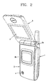
- Figure 2 is a diagram showing an operation of the conventional folder type mobile terminal.
- the conventional mobile terminal is comprised of: a main body 1 having a plurality of buttons 1 a thereon; a folder 3 rotatably-coupled to the main body 1 by its one end through a hinge portion 3a, installed to be opened or closed (i.e., folded or unfolded) with respect to the terminal main body 1, protecting the terminal main body 1, and having a main display portion 2 thereon which allows to see a counterpart therethrough; and a camera 4 mounted on the folder 3.
- a sub-display portion 3b is installed at the front side of the folder 3 to see an image shot by the camera 4.
- a counterpart shooting mode after a user adjusts a position of the camera 4 to be focused on the counterpart with the folder 3 being moved, the user films the counterpart by pressing the buttons 1 a. Thereafter, the user can see the shot image through the main display portion 2.
- the user adjusts the position of the camera 4 to be focused on the user himself/herself by turning back the folder 3, the user presses the button 1a to shoot himself/herself. Thereafter, the user can see the shot image through the sub-display portion 3b.
- the conventional mobile terminal has a simple structure which can be only embodied to open the folder as much as 120 ⁇ 180°. Thus, because it has a limited open angle for the folder, it is inconvenient to fold and unfold the folder.
- the user can not see the main display portion, but rather shoots himself/herself with seeing only the sub-display portion. As a result of this, it is inconvenient to use the mobile terminal for that purpose.
- an object of the present invention is to provide a mobile terminal having a double rotation structure by which a folder can be freely opened and closed (i.e., folded and unfolded) through a connection member which couples a main body to the folder, and a position of a camera installed in the connection member can be freely adjusted.
- a mobile terminal having a double rotation structure comprising: a main body having a plurality of keys thereon for inputting information and operating functions; a folder having a display portion thereon; a connection member including a first connecting portion having a camera therein and a second connecting portion integrally formed with the first connecting portion, and rotatably coupling the main body to the first connecting portion and the folder to the second connecting portion; and a connection member locking unit installed at one side of the main body in order to stop rotation of the connection member selectively.
- a first receiving groove is formed for reception of the connection member at one side of the main body, and a second receiving groove is also formed for reception of the connection member at one side of the folder.
- a first hinge groove is formed at one surface of the first connecting portion, a first hinge axis is formed at one surface of the main body to be inserted in the first hinge groove, a second hinge groove is a Iso formed atone surface of the second connecting portion to correspond to the first hinge groove, and a second hinge axis is formed at one surface of the folder to be inserted in the second hinge groove.
- a first auxiliary groove is formed at the other surface of the first connecting portion, a first mounting groove is formed at the other surface of the main body, a second auxiliary groove is formed at the other surface of the second connecting portion, and a second mounting groove is formed at the other surface of the folder. Also, a first auxiliary pin is inserted in the first auxiliary groove and the first mounting groove, and a second a uxiliary pin is inserted in the second a uxiliary groove and the second mounting groove.
- the first auxiliary pin is comprised of a first fixing portion inserted in the first mounting groove, and a first rotating portion coupled rotatably and axially to the first fixing portion and inserted in the first auxiliary groove.
- the second auxiliary pin is comprised of: a second fixing portion inserted in the second mounting groove, and a second rotating portion coupled rotatably and axially to the second fixing portion and inserted in the second auxiliary groove.
- the main body is rotatably installed centering around the first hinge axis and the first auxiliary pin.
- the folder is rotatably installed centering around the second hinge axis and the second auxiliary pin.
- the first connecting portion is rotatably installed centering around the first hinge axis and the first auxiliary pin
- the second connecting portion is rotatably installed centering around the second hinge axis and the second auxiliary pin.
- connection member locking unit is comprised of: a slider installed to be slid in the main body and having a locking projection formed at one surface thereof to be selectively inserted into a locking groove placed in the connection member, and a hand grip formed at the other surface thereof; and a spring installed adjacent to the slider to move the slider flexibly.
- a slot is formed at an upper surface of the main body, and the hand grip is exposed out of the main body through the slot.
- a stopping jaw is formed between the first and second connecting portions of the connection member.
- the stopping jaw thereby constantly maintains an opened angle of the folder when it is opened.
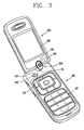
- Figure 3 is a perspective view showing a mobile terminal having a double rotation structure in accordance with the present invention
- Figure 4 is a side view of Figure 3
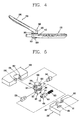
- Figure 5 is a disassembled perspective view showing main parts of the mobile terminal having a double rotation structure in accordance with the present invention
- Figure 6 is a side view showing a first auxiliary pin of the mobile terminal having a double rotation structure in accordance with the present invention
- Figure 7 is a cross-sectional view showing a second auxiliary pin of the mobile terminal having a double rotation structure in accordance with the present invention
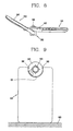
- Figure 8 is a side view illustrating a connection member in a rotated state of the mobile terminal having a double rotation structure in accordance with the present invention.
- the mobile terminal having a double rotation structure in accordance with the present invention includes: a main body 100 having a plurality of keys 107 thereon to input information and operate functions; a folder 200 having a display portion 205 thereon; a connection member 300 having a first connecting portion 310 with a camera 500 therein and a second connecting portion 320 integrally formed with the first connecting portion 310, in which the first connecting portion 310 is rotatably coupled to the main body 100 and the second connecting portion 320 is rotatably coupled to the folder 200; and a connection member locking unit 400 installed at one side of the main body 100 to selectively stop a rotation of the connection member 300.
- a first receiving groove 101 is formed at one side of the main body 100 for reception of the connection member 300, and a second receiving groove 201 is formed at one side of the folder 200 for reception of the connection member 300.
- a first hinge groove 311 is formed at one surface of the first connecting portion 310 and a first hinge axis 103 is formed at one surface of the main body 100, in particular, at an inner circumferential surface of the first receiving groove 101, to be inserted in the first hinge groove 311.
- a second hinge groove 321 is formed at one surface of the second connecting portion 320 to correspond with the first hinge groove 311, and a second hinge axis 203 is formed at one surface of the folder 200, in particular, at an inner circumferential surface of the second receiving groove 201, to be inserted in the second hinge groove 321.
- the first hinge groove 311 and the second hinge groove 321 of the connection member 300 are crossed each other, and the first hinge axis 103 and the second hinge axis 203 are also crossed each other.
- a first auxiliary groove 312 is formed at the other side of the first connecting p ortion 310, a nd a first mounting g roove 1 02 i s formed at t he other side of the main body 100.
- a first auxiliary pin 330 is inserted in the first auxiliary groove 312 and the first mounting groove 102.
- a second auxiliary groove 322 is formed at the other side of the second connecting portion 320, and a second mounting groove 202 is formed at the other side of the folder 200.
- a second auxiliary pin 340 is inserted in the second auxiliary groove 322 and the second mounting groove 202.
- the first auxiliary pin 330 is comprised of: a first fixing portion 331 inserted in the first mounting groove 102: and a first rotating portion 332 coupled rotatably and axially to the first fixing portion 331 and inserted to the first auxiliary groove 312.
- the second auxiliary pin 340 is also comprised of: a second fixing portion 431 inserted in the second mounting groove 202, and a second rotating portion 432 coupled rotatably and axially to the second fixing portion 431 and inserted to the second auxiliary groove 322.
- the main body 100 is rotatably installed centering around the first hinge axis 103 and the first auxiliary pin 330.
- the folder 200 is also rotatably installed centering around the second hinge axis 203 and the second auxiliary pin 340.
- the main body 100 is rotatably installed centering around the first hinge axis 103 and the first auxiliary pin 330.
- the folder 200 is also rotatably installed centering around the second hinge axis 203 and the second auxiliary pin 340.
- the connection member 300 can be rotated as much as a certain angle in a state that the main body 100 and the folder 200 are not rotated. That is, in the mobile terminal having a double rotation structure in accordance with the present invention, the folder can be rotated and the connection member can also be rotated with the folder being left as it is.
- the user when desiring to shoot himself/herself using the camera, the user shot an image with watching the sub-display portion formed at the front surface of the folder by turning the mobile terminal itself as much as 180°.
- the mobile terminal having the double rotation structure in accordance with the present invention there is no use of moving the folder 200 and the main body 100, because the connection member 300 is rotated in order for the camera 500 to face the user himself/herself.
- the first connecting portion 310 is rotatably installed centering around the first hinge axis 103 and the first auxiliary pin 330
- the second connecting portion 320 is rotatably installed centering around the second hinge axis 203 and the second auxiliary pin 340.
- connection member locking unit 400 used for the connection member 300 not to be moved arbitrarily.
- connection member locking unit 400 fixes the connection member 300 not to be rotated during a voice transmitting/receiving mode(General Mode).
- connection member locking unit 400 performs a function of converting the connection member 300 into a rotatable state.
- connection member locking member 400 is comprised of: a slider 410 installed to be slid in the main body 100 and having a locking projection 411 formed at one surface thereof to be selectively inserted in a locking groove 301 placed in the connection member 300, and a hand grip 412 formed at the other surface t hereof; and a s pring 4 20 installed adjacent to the s paramount 410 t o flexibly move the slider 410.
- a slot 105 is formed at the upper surface of the main body 100, and the hand grip 412 is exposed out of the main body 100 through the slot 105.
- a stopping jaw 303 is formed at a part of an outer circumferential surface of the second connecting portion 320 in the connection member 300, to allow the opened angle of the folder 200 to be constant when the folder 200 is opened.
- a user can talk over the phone with his/her counterpart by using the buttons 107.
- the folder 200 is rotated centering around the first hinge axis 203 and the second auxiliary pin 340.
- the folder 200 maintains its constant opened angle by the stopping jaw 303 formed at a part of the middle portion of the outer circumferential surface of the connection member 300. According to this, the user can conveniently talk over the phone with his/her counterpart.
- connection member locking unit 400 Furthermore, during a user himself/herself shooting mode, the user should release a locking state of the connection member locking unit 400 to convert it into a rotatable state.
- the locking projection 411 of the slider 410 falls out of the locking groove 301 by pushing it toward the spring 420 with a knob 412 held, thereby maintaining the rotatable state of the connection member 300.
- the first connecting portion 310 is rotated centering around the first hinge axis 103 and the first auxiliary pin 330
- the second connecting portion 320 is rotated centering around the second hinge axis 203 and the second auxiliary pin 340.
- the direction of the camera 500 installed at the front surface of the first connecting portion 310 of the connection member 300 is converted to face the user. Accordingly, t he u ser c an conveniently s hoot himself/herself by converting the direction of the camera 500 without turning the folder 200 by 180°.
- Figure 9 is a front view showing a state that the mobile terminal having the double rotation structure in accordance with the present invention is installed at right angles to the bottom surface
- Figure 10 is a side view of the state shown in Figure 9.
- the position of camera 500 is adjusted to face a subject (not shown), and thereby the user can shoot an image.
- the user uses the mobile terminal with putting it on the bottom surface 600 of indoor or the table, without holding it with hands.
- the user can conveniently shoot an image by making the folder 200 and the main body 100 have a function such as a tripod supporting a general camera.
- the folder can be freely opened and closed through the connection member coupling the main body to the folder and the position of the camera installed at the connection member can be freely adjusted.
Abstract
Description
- The present invention relates to a mobile terminal having a double rotation structure, and particularly, to a mobile terminal having a double rotation structure by which a folder can be freely folded and unfolded through a connection member which couples a main body and the folder, and a position of a camera installed in the connection member can be freely adjusted.
- A mobile terminal provides functions of a multimedia and an internet as well as a function which simply transmits voice or data. Also, the mobile terminal has a camera therein and thus can transmit/receive an image shot by the camera to/from a counter mobile terminal.
- Figure 1 is a perspective view showing a conventional folder type mobile terminal, and Figure 2 is a diagram showing an operation of the conventional folder type mobile terminal.
- Referring to Figures 1 and 2, the conventional mobile terminal is comprised of: a main body 1 having a plurality of buttons 1 a thereon; a
folder 3 rotatably-coupled to the main body 1 by its one end through ahinge portion 3a, installed to be opened or closed (i.e., folded or unfolded) with respect to the terminal main body 1, protecting the terminal main body 1, and having a main display portion 2 thereon which allows to see a counterpart therethrough; and acamera 4 mounted on thefolder 3. - A
sub-display portion 3b is installed at the front side of thefolder 3 to see an image shot by thecamera 4. - In the conventional mobile terminal, constructed as aforementioned, during a voice transmitting/receiving mode, a user rotates the
folder 3 as much as a certain angle centering around thehinge portion 3a to open it, as can be seen from Figure 2. - Also, during a counterpart shooting mode, after a user adjusts a position of the
camera 4 to be focused on the counterpart with thefolder 3 being moved, the user films the counterpart by pressing the buttons 1 a. Thereafter, the user can see the shot image through the main display portion 2. - Furthermore, during a user himself/herself shooting mode, after the user adjusts the position of the
camera 4 to be focused on the user himself/herself by turning back thefolder 3, the user presses the button 1a to shoot himself/herself. Thereafter, the user can see the shot image through thesub-display portion 3b. - However, the conventional mobile terminal has a simple structure which can be only embodied to open the folder as much as 120~180°. Thus, because it has a limited open angle for the folder, it is inconvenient to fold and unfold the folder.
- Moreover, during the user himself/herself shooting mode, due to the structure of the mobile terminal, the user can not see the main display portion, but rather shoots himself/herself with seeing only the sub-display portion. As a result of this, it is inconvenient to use the mobile terminal for that purpose.
- Therefore, an object of the present invention is to provide a mobile terminal having a double rotation structure by which a folder can be freely opened and closed (i.e., folded and unfolded) through a connection member which couples a main body to the folder, and a position of a camera installed in the connection member can be freely adjusted.
- To achieve these and other advantages and in accordance with the purpose of the present invention, as embodied and broadly described herein, there is provided a mobile terminal having a double rotation structure, comprising: a main body having a plurality of keys thereon for inputting information and operating functions; a folder having a display portion thereon; a connection member including a first connecting portion having a camera therein and a second connecting portion integrally formed with the first connecting portion, and rotatably coupling the main body to the first connecting portion and the folder to the second connecting portion; and a connection member locking unit installed at one side of the main body in order to stop rotation of the connection member selectively.
- A first receiving groove is formed for reception of the connection member at one side of the main body, and a second receiving groove is also formed for reception of the connection member at one side of the folder.
- A first hinge groove is formed at one surface of the first connecting portion, a first hinge axis is formed at one surface of the main body to be inserted in the first hinge groove, a second hinge groove is a Iso formed atone surface of the second connecting portion to correspond to the first hinge groove, and a second hinge axis is formed at one surface of the folder to be inserted in the second hinge groove.
- A first auxiliary groove is formed at the other surface of the first connecting portion, a first mounting groove is formed at the other surface of the main body, a second auxiliary groove is formed at the other surface of the second connecting portion, and a second mounting groove is formed at the other surface of the folder. Also, a first auxiliary pin is inserted in the first auxiliary groove and the first mounting groove, and a second a uxiliary pin is inserted in the second a uxiliary groove and the second mounting groove.
- The first auxiliary pin is comprised of a first fixing portion inserted in the first mounting groove, and a first rotating portion coupled rotatably and axially to the first fixing portion and inserted in the first auxiliary groove. The second auxiliary pin, on the other hand, is comprised of: a second fixing portion inserted in the second mounting groove, and a second rotating portion coupled rotatably and axially to the second fixing portion and inserted in the second auxiliary groove.
- The main body is rotatably installed centering around the first hinge axis and the first auxiliary pin. The folder is rotatably installed centering around the second hinge axis and the second auxiliary pin.
- The first connecting portion is rotatably installed centering around the first hinge axis and the first auxiliary pin, and the second connecting portion is rotatably installed centering around the second hinge axis and the second auxiliary pin.
- The connection member locking unit is comprised of: a slider installed to be slid in the main body and having a locking projection formed at one surface thereof to be selectively inserted into a locking groove placed in the connection member, and a hand grip formed at the other surface thereof; and a spring installed adjacent to the slider to move the slider flexibly.
- A slot is formed at an upper surface of the main body, and the hand grip is exposed out of the main body through the slot.
- A stopping jaw is formed between the first and second connecting portions of the connection member. The stopping jaw thereby constantly maintains an opened angle of the folder when it is opened.
- The foregoing and other objects, features, aspects and advantages of the present invention will become more apparent from the following detailed description of the present invention when taken in conjunction with the accompanying drawings.
- The accompanying drawings, which are included to provide a further understanding of the invention and are incorporated in and constitute a part of this specification, illustrate embodiments of the invention and together with the description serve to explain the principles of the invention.
- In the drawings:
- Figure 1 is a perspective view illustrating a conventional folder type mobile terminal;
- Figure 2 is a diagram showing an operation of a conventional folder type mobile terminal;
- Figure 3 is a perspective view illustrating a mobile terminal having a double rotation structure in accordance with the present invention;
- Figure 4 is a side view of the mobile terminal shown in Figure 3;
- Figure 5 is a disassembled perspective view showing main parts of a mobile terminal having a double rotation structure in accordance with the present invention;
- Figure 6 is a cross-sectional view showing a first auxiliary pin of a mobile terminal having a double rotation structure in accordance with the present invention;
- Figure 7 is a cross-sectional view showing a second auxiliary pin of a mobile terminal having a double rotation structure in accordance with the present invention;
- Figure 8 is a side view illustrating a connection member in a rotated state, of a mobile terminal having a double rotation structure in accordance with the present invention;
- Figure 9 is a front view showing a state that a mobile terminal having a double rotation structure is installed at right angles to a bottom surface in accordance with the present invention; and
- Figure 10 is a side view of the state shown in Figure 9.
-
- Reference will now be made in detail to the preferred embodiments of the present invention, examples of which are illustrated in the accompanying drawings.
- A mobile t erminal h aving a d ouble rotation structure in a ccordance with the present invention will be described with reference to attached drawings as follows.
- Figure 3 is a perspective view showing a mobile terminal having a double rotation structure in accordance with the present invention, Figure 4 is a side view of Figure 3, Figure 5 is a disassembled perspective view showing main parts of the mobile terminal having a double rotation structure in accordance with the present invention, Figure 6 is a side view showing a first auxiliary pin of the mobile terminal having a double rotation structure in accordance with the present invention, Figure 7 is a cross-sectional view showing a second auxiliary pin of the mobile terminal having a double rotation structure in accordance with the present invention, and Figure 8 is a side view illustrating a connection member in a rotated state of the mobile terminal having a double rotation structure in accordance with the present invention.
- As shown in those drawings, the mobile terminal having a double rotation structure in accordance with the present invention includes: a
main body 100 having a plurality ofkeys 107 thereon to input information and operate functions; afolder 200 having adisplay portion 205 thereon; aconnection member 300 having a first connectingportion 310 with acamera 500 therein and a second connectingportion 320 integrally formed with the first connectingportion 310, in which the first connectingportion 310 is rotatably coupled to themain body 100 and the second connectingportion 320 is rotatably coupled to thefolder 200; and a connectionmember locking unit 400 installed at one side of themain body 100 to selectively stop a rotation of theconnection member 300. - A first receiving
groove 101 is formed at one side of themain body 100 for reception of theconnection member 300, and a second receivinggroove 201 is formed at one side of thefolder 200 for reception of theconnection member 300. - A
first hinge groove 311 is formed at one surface of the first connectingportion 310 and afirst hinge axis 103 is formed at one surface of themain body 100, in particular, at an inner circumferential surface of thefirst receiving groove 101, to be inserted in thefirst hinge groove 311. - A
second hinge groove 321 is formed at one surface of the second connectingportion 320 to correspond with thefirst hinge groove 311, and asecond hinge axis 203 is formed at one surface of thefolder 200, in particular, at an inner circumferential surface of the second receivinggroove 201, to be inserted in thesecond hinge groove 321. - The
first hinge groove 311 and thesecond hinge groove 321 of theconnection member 300 are crossed each other, and thefirst hinge axis 103 and thesecond hinge axis 203 are also crossed each other. - A first
auxiliary groove 312 is formed at the other side of the first connectingp ortion 310, a nd a first mounting g roove 1 02 i s formed at t he other side of themain body 100. - A first
auxiliary pin 330 is inserted in the firstauxiliary groove 312 and thefirst mounting groove 102. - Moreover, a second
auxiliary groove 322 is formed at the other side of the second connectingportion 320, and asecond mounting groove 202 is formed at the other side of thefolder 200. - A second
auxiliary pin 340 is inserted in the secondauxiliary groove 322 and thesecond mounting groove 202. - As can be seen from Figure 6, the first
auxiliary pin 330 is comprised of: afirst fixing portion 331 inserted in the first mounting groove 102: and a first rotatingportion 332 coupled rotatably and axially to thefirst fixing portion 331 and inserted to the firstauxiliary groove 312. - As can be seen from Figure 7, the second
auxiliary pin 340 is also comprised of: a second fixing portion 431 inserted in thesecond mounting groove 202, and a second rotating portion 432 coupled rotatably and axially to the second fixing portion 431 and inserted to the secondauxiliary groove 322. - The
main body 100 is rotatably installed centering around thefirst hinge axis 103 and the firstauxiliary pin 330. Thefolder 200 is also rotatably installed centering around thesecond hinge axis 203 and the secondauxiliary pin 340. - As aforementioned, the
main body 100 is rotatably installed centering around thefirst hinge axis 103 and the firstauxiliary pin 330. Thefolder 200 is also rotatably installed centering around thesecond hinge axis 203 and the secondauxiliary pin 340. Furthermore, as can be seen from Figure 8, theconnection member 300 can be rotated as much as a certain angle in a state that themain body 100 and thefolder 200 are not rotated. That is, in the mobile terminal having a double rotation structure in accordance with the present invention, the folder can be rotated and the connection member can also be rotated with the folder being left as it is. - In this double rotation structure, because a user can freely adjust a direction of the
camera 500 installed in theconnection member 300 toward the user himself/herself or his/her counterpart, the user can conveniently shoot an image with watching the main display portion at any time. - That is, in the conventional mobile terminal, when desiring to shoot himself/herself using the camera, the user shot an image with watching the sub-display portion formed at the front surface of the folder by turning the mobile terminal itself as much as 180°.
- However, in the mobile terminal having the double rotation structure in accordance with the present invention, there is no use of moving the
folder 200 and themain body 100, because theconnection member 300 is rotated in order for thecamera 500 to face the user himself/herself. - To achieve these functions, the first connecting
portion 310 is rotatably installed centering around thefirst hinge axis 103 and the firstauxiliary pin 330, and the second connectingportion 320 is rotatably installed centering around thesecond hinge axis 203 and the secondauxiliary pin 340. - Hereinafter, it will be described about the connection
member locking unit 400 used for theconnection member 300 not to be moved arbitrarily. - The connection
member locking unit 400 fixes theconnection member 300 not to be rotated during a voice transmitting/receiving mode(General Mode). - Only in case that the rotation of the
connection member 300 is required, such as the user himself/herself shooting mode, the connectionmember locking unit 400 performs a function of converting theconnection member 300 into a rotatable state. - The connection
member locking member 400 is comprised of: aslider 410 installed to be slid in themain body 100 and having a lockingprojection 411 formed at one surface thereof to be selectively inserted in a lockinggroove 301 placed in theconnection member 300, and ahand grip 412 formed at the other surface t hereof; and a spring 4 20 installed adjacent to the s lider 410 t o flexibly move theslider 410. - A
slot 105 is formed at the upper surface of themain body 100, and thehand grip 412 is exposed out of themain body 100 through theslot 105. - Furthermore, a stopping
jaw 303 is formed at a part of an outer circumferential surface of the second connectingportion 320 in theconnection member 300, to allow the opened angle of thefolder 200 to be constant when thefolder 200 is opened. - An operation of the mobile terminal having such double rotation structure, as aforementioned, will now be explained.
- During a voice transmitting/receiving mode, as shown in Figures 3 and 4, after rotating the
folder 200 by a certain angle centering around theconnection member 300 to open it, a user can talk over the phone with his/her counterpart by using thebuttons 107. Here, thefolder 200 is rotated centering around thefirst hinge axis 203 and the secondauxiliary pin 340. When thefolder 200 is opened, thefolder 200 maintains its constant opened angle by the stoppingjaw 303 formed at a part of the middle portion of the outer circumferential surface of theconnection member 300. According to this, the user can conveniently talk over the phone with his/her counterpart. - As can be seen from Figure 4, during a counterpart shooting mode, a user properly adjusts a position of the
camera 500 to his/her counterpart, thereafter shoots an image by pressing thebuttons 107, and then can see the shot result through thedisplay portion 205. - Furthermore, during a user himself/herself shooting mode, the user should release a locking state of the connection
member locking unit 400 to convert it into a rotatable state. - That is, under the state of the
folder 200 being opened, the lockingprojection 411 of theslider 410 falls out of the lockinggroove 301 by pushing it toward thespring 420 with aknob 412 held, thereby maintaining the rotatable state of theconnection member 300. In this rotatable state, the first connectingportion 310 is rotated centering around thefirst hinge axis 103 and the firstauxiliary pin 330, and the second connectingportion 320 is rotated centering around thesecond hinge axis 203 and the secondauxiliary pin 340. According to this, the direction of thecamera 500 installed at the front surface of the first connectingportion 310 of theconnection member 300 is converted to face the user. Accordingly, t he u ser c an conveniently s hoot himself/herself by converting the direction of thecamera 500 without turning thefolder 200 by 180°. - On the other side, Figure 9 is a front view showing a state that the mobile terminal having the double rotation structure in accordance with the present invention is installed at right angles to the bottom surface, and Figure 10 is a side view of the state shown in Figure 9.
- As shown in Figures 9 and 10, once putting the mobile terminal on a
bottom surface 600 of indoor or a table, the position ofcamera 500 is adjusted to face a subject (not shown), and thereby the user can shoot an image. Thus, the user uses the mobile terminal with putting it on thebottom surface 600 of indoor or the table, without holding it with hands. As a result, the user can conveniently shoot an image by making thefolder 200 and themain body 100 have a function such as a tripod supporting a general camera. - As stated above, in the mobile terminal having the double rotation structure in accordance with the present invention, by adopting the double rotation structure in which the folder can be rotated and the connection member can be also rotated with the folder being left as it is, the folder can be freely opened and closed through the connection member coupling the main body to the folder and the position of the camera installed at the connection member can be freely adjusted.
- As the present invention may be embodied in several forms without departing from the spirit or essential characteristics thereof, it should also be understood that the above-described embodiments are not limited by any of the details of the foregoing description, unless otherwise specified, but rather should be construed broadly within its spirit and scope as defined in the appended claims, and therefore all changes and modifications that fall within the metes and bounds of the claims, or equivalence of such metes and bounds are therefore intended to be embraced by the appended claims.
Claims (13)
- A mobile terminal having a double rotation structure, comprising:a main body having a plurality of keys thereon to input information and operate its functions;a folder having a display portion thereon;a connection member having a first connecting portion and a second connecting portion integrally formed with the first connecting portion therein, wherein the first connecting portion is rotatably coupled to the main body and the second connecting portion is rotatably coupled to the folder; anda connection member locking unit installed at one side of the main body to selectively stop a rotation of the connection member.
- The mobile terminal of claim 1, wherein a first receiving groove is formed at one side of the main body for reception of the connection member, and a second receiving groove is formed at one side of the folder for reception of the connection member.
- The mobile terminal of claim 1, wherein a first hinge groove is formed at one surface of the first connecting portion, a first hinge axis is formed at one surface of the main body to be inserted in the first hinge groove, a second hinge groove is formed at one surface of the second connecting portion to correspond with the first hinge groove, and a second hinge axis is formed at one surface of the folder to be inserted in the second hinge groove.
- The mobile terminal of claim 3, wherein a first auxiliary groove is formed at the other side of the first connecting portion, a first mounting groove is formed at the other side of the main body, a second auxiliary groove is formed at the other side of the second connecting portion, a second mounting groove is formed at the other side of the folder, a first auxiliary pin is inserted in the first auxiliary groove and the first mounting groove, and a second auxiliary pin is inserted in the second auxiliary groove and the second mounting groove.
- The mobile terminal of claim 3, wherein a first auxiliary groove is formed at the other side of the first connecting portion, a first mounting groove is formed at the other side of the main body, a second auxiliary groove is formed at the other side of the second connecting portion, a second mounting groove is formed at the other side of the folder, a first auxiliary pin is inserted in the first auxiliary groove and the first mounting groove, and a second auxiliary pin is inserted in the second auxiliary groove and the second mounting groove.
- The mobile terminal of claim 5, wherein the first auxiliary pin is comprised of a first fixing portion inserted in the first mounting groove, and a first rotating portion coupled rotatably and axially to the first fixing portion and inserted to the first auxiliary groove; and
the second auxiliary pin is comprised of a second fixing portion inserted in the second mounting groove, and a second rotating portion coupled rotatably and axially to the second fixing portion and inserted in the second auxiliary groove. - The mobile terminal of claim 5, wherein the main body is rotatably installed c entering a round the first h inge axis a nd t he first a uxiliary p in a nd the folder is rotatably installed centering around the second hinge axis and the second auxiliary pin.
- The mobile terminal of claim 5, wherein the first connecting portion is rotatably installed centering around the first hinge axis and the first auxiliary pin, and the second connecting portion is rotatably installed centering around the second hinge axis and the second auxiliary pin.
- The mobile terminal of claim 1, wherein the connection member locking member, comprising:a slider installed to be slid in the main body, and having a locking projection formed at one surface thereof to be selectively inserted in a locking groove placed in the connection member, and a hand grip formed at the other surface thereof; anda spring installed adjacent to the slider to flexibly move the slider.
- The mobile terminal of claim 9, wherein a slot is formed at the upper surface of the main body, and the hand grip is exposed out of the main body through the slot.
- The mobile terminal of claim 1, wherein a stopping jaw is formed at a part of an outer circumferential surface of the second connecting portion in the connection member, to allow the opened angle of the folder to be constant when the folder is opened.
- The mobile terminal of claim 1, wherein the camera is installed at the front surface of the first connecting portion of the connection member.
- A mobile terminal having a double rotation structure, comprising:a m ain body having a p lurality of keys thereon to input i nformation and operate its functions;a folder having a display portion thereon;a connection member having a first connecting portion with a camera therein and a second connecting portion integrally formed with the first connecting portion, wherein the first connecting portion is rotatably coupled to the main body and the second connecting portion is rotatably coupled to the folder; anda connection member locking unit installed at one side of the main body to selectively stop a rotation of the connection member.
Applications Claiming Priority (2)
| Application Number | Priority Date | Filing Date | Title |
|---|---|---|---|
| KR2003097981 | 2003-12-26 | ||
| KR1020030097981A KR100595640B1 (en) | 2003-12-26 | 2003-12-26 | Double rotation open/close apparatus for portable terminal |
Publications (2)
| Publication Number | Publication Date |
|---|---|
| EP1549030A1 true EP1549030A1 (en) | 2005-06-29 |
| EP1549030B1 EP1549030B1 (en) | 2011-02-02 |
Family
ID=34545920
Family Applications (1)
| Application Number | Title | Priority Date | Filing Date |
|---|---|---|---|
| EP04030682A Not-in-force EP1549030B1 (en) | 2003-12-26 | 2004-12-23 | Mobile terminal having double rotation structure |
Country Status (7)
| Country | Link |
|---|---|
| US (1) | US7672697B2 (en) |
| EP (1) | EP1549030B1 (en) |
| JP (1) | JP4383334B2 (en) |
| KR (1) | KR100595640B1 (en) |
| CN (1) | CN100481844C (en) |
| AT (1) | ATE497671T1 (en) |
| DE (1) | DE602004031280D1 (en) |
Cited By (3)
| Publication number | Priority date | Publication date | Assignee | Title |
|---|---|---|---|---|
| EP1730960A1 (en) * | 2004-04-02 | 2006-12-13 | Sagem Communication | Multifunctional terminal with a hinge incorporating an imaging device |
| CN101630055B (en) * | 2008-07-17 | 2011-07-27 | 鸿富锦精密工业(深圳)有限公司 | Electronic device with photographic function |
| CN102707881A (en) * | 2012-04-26 | 2012-10-03 | 苏州佳世达电通有限公司 | Electronic device and control method thereof |
Families Citing this family (9)
| Publication number | Priority date | Publication date | Assignee | Title |
|---|---|---|---|---|
| JP4071568B2 (en) * | 2002-07-30 | 2008-04-02 | シャープ株式会社 | Portable device |
| EP1434170A3 (en) * | 2002-11-07 | 2006-04-05 | Matsushita Electric Industrial Co., Ltd. | Method and apparatus for adding ornaments to an image of a person |
| KR100630068B1 (en) * | 2005-01-25 | 2006-09-27 | 삼성전자주식회사 | Hinge device for display rotation type mobile phone |
| WO2007023672A1 (en) * | 2005-08-22 | 2007-03-01 | Sugatsune Kogyo Co., Ltd. | Hinge device |
| JP2007110346A (en) * | 2005-10-12 | 2007-04-26 | Omron Corp | Connection mechanism and mobile terminal |
| TWM304172U (en) * | 2006-07-11 | 2007-01-01 | Quanta Comp Inc | Hand held apparatus and an active flip device for a foldable cover thereof |
| JP4670939B2 (en) * | 2008-11-05 | 2011-04-13 | ソニー株式会社 | Imaging apparatus and display control method for imaging apparatus |
| TWI647560B (en) * | 2016-04-25 | 2019-01-11 | 仁寶電腦工業股份有限公司 | Rotary shaft structure and portable electronic device |
| CN110133985A (en) * | 2018-09-29 | 2019-08-16 | 广东小天才科技有限公司 | Smart host and intelligent wearable device with the smart host |
Citations (8)
| Publication number | Priority date | Publication date | Assignee | Title |
|---|---|---|---|---|
| EP0898405A2 (en) | 1997-08-22 | 1999-02-24 | Hitachi, Ltd. | Information communication terminal device |
| US20010004269A1 (en) * | 1999-12-14 | 2001-06-21 | Junichiro Shibata | Portable terminal |
| JP2001298516A (en) * | 2000-04-12 | 2001-10-26 | Matsushita Electric Ind Co Ltd | Portable radio communication equipment |
| WO2002091604A2 (en) | 2001-05-03 | 2002-11-14 | Phoenix Korea Co., Ltd. | Hinge device |
| EP1267576A2 (en) * | 2001-06-12 | 2002-12-18 | Lg Electronics Inc. | Portable phone with camera |
| US20030109232A1 (en) * | 2001-12-08 | 2003-06-12 | Samsung Electronics Co., Ltd. | Camera lens mounting device of folder type telephone |
| US20030125079A1 (en) * | 2001-12-29 | 2003-07-03 | Samsung Electronics Co., Ltd. | Mobile communication unit with camera lens opening means in closed folder |
| GB2387063A (en) | 2002-03-29 | 2003-10-01 | Nec Corp | Foldable information apparatus with rotatable display and camera |
Family Cites Families (6)
| Publication number | Priority date | Publication date | Assignee | Title |
|---|---|---|---|---|
| JP3642261B2 (en) | 2000-05-16 | 2005-04-27 | 日本電気株式会社 | Wireless terminal |
| KR100665709B1 (en) * | 2001-04-26 | 2007-01-10 | 피닉스코리아 주식회사 | Hinge device |
| US6941618B2 (en) * | 2002-09-13 | 2005-09-13 | Samsung Electronics Co., Ltd. | Hinge device for portable wireless terminal |
| KR100504138B1 (en) * | 2002-11-12 | 2005-07-27 | 삼성전자주식회사 | Hinge device for portable wireless terminal |
| JP4238571B2 (en) * | 2002-12-06 | 2009-03-18 | 日本電気株式会社 | Foldable portable device, its wiring device and wiring method |
| JP2004312476A (en) * | 2003-04-09 | 2004-11-04 | Nec Corp | Foldable portable information terminal |
-
2003
- 2003-12-26 KR KR1020030097981A patent/KR100595640B1/en not_active IP Right Cessation
-
2004
- 2004-12-21 JP JP2004370272A patent/JP4383334B2/en not_active Expired - Fee Related
- 2004-12-23 US US11/021,227 patent/US7672697B2/en not_active Expired - Fee Related
- 2004-12-23 EP EP04030682A patent/EP1549030B1/en not_active Not-in-force
- 2004-12-23 AT AT04030682T patent/ATE497671T1/en not_active IP Right Cessation
- 2004-12-23 DE DE602004031280T patent/DE602004031280D1/en active Active
- 2004-12-27 CN CNB2004101032665A patent/CN100481844C/en not_active Expired - Fee Related
Patent Citations (8)
| Publication number | Priority date | Publication date | Assignee | Title |
|---|---|---|---|---|
| EP0898405A2 (en) | 1997-08-22 | 1999-02-24 | Hitachi, Ltd. | Information communication terminal device |
| US20010004269A1 (en) * | 1999-12-14 | 2001-06-21 | Junichiro Shibata | Portable terminal |
| JP2001298516A (en) * | 2000-04-12 | 2001-10-26 | Matsushita Electric Ind Co Ltd | Portable radio communication equipment |
| WO2002091604A2 (en) | 2001-05-03 | 2002-11-14 | Phoenix Korea Co., Ltd. | Hinge device |
| EP1267576A2 (en) * | 2001-06-12 | 2002-12-18 | Lg Electronics Inc. | Portable phone with camera |
| US20030109232A1 (en) * | 2001-12-08 | 2003-06-12 | Samsung Electronics Co., Ltd. | Camera lens mounting device of folder type telephone |
| US20030125079A1 (en) * | 2001-12-29 | 2003-07-03 | Samsung Electronics Co., Ltd. | Mobile communication unit with camera lens opening means in closed folder |
| GB2387063A (en) | 2002-03-29 | 2003-10-01 | Nec Corp | Foldable information apparatus with rotatable display and camera |
Non-Patent Citations (1)
| Title |
|---|
| PATENT ABSTRACTS OF JAPAN vol. 2002, no. 02 2 April 2002 (2002-04-02) * |
Cited By (3)
| Publication number | Priority date | Publication date | Assignee | Title |
|---|---|---|---|---|
| EP1730960A1 (en) * | 2004-04-02 | 2006-12-13 | Sagem Communication | Multifunctional terminal with a hinge incorporating an imaging device |
| CN101630055B (en) * | 2008-07-17 | 2011-07-27 | 鸿富锦精密工业(深圳)有限公司 | Electronic device with photographic function |
| CN102707881A (en) * | 2012-04-26 | 2012-10-03 | 苏州佳世达电通有限公司 | Electronic device and control method thereof |
Also Published As
| Publication number | Publication date |
|---|---|
| US20050153679A1 (en) | 2005-07-14 |
| DE602004031280D1 (en) | 2011-03-17 |
| KR20050066671A (en) | 2005-06-30 |
| US7672697B2 (en) | 2010-03-02 |
| EP1549030B1 (en) | 2011-02-02 |
| ATE497671T1 (en) | 2011-02-15 |
| JP4383334B2 (en) | 2009-12-16 |
| CN100481844C (en) | 2009-04-22 |
| JP2005198276A (en) | 2005-07-21 |
| CN1655563A (en) | 2005-08-17 |
| KR100595640B1 (en) | 2006-06-30 |
Similar Documents
| Publication | Publication Date | Title |
|---|---|---|
| JP4578727B2 (en) | Information terminal device provided with camera with rotation function | |
| EP1484920B1 (en) | Poratable communication device | |
| JP2004215180A (en) | Portable radio terminal | |
| EP1549030A1 (en) | Mobile terminal having double rotation structure | |
| US8032192B2 (en) | Portable terminal and sliding/swing-type cradling apparatus thereof | |
| JPH1075287A (en) | Portable video telephone | |
| JP2008014497A (en) | Hinge device for portable wireless terminal | |
| EP1684491A2 (en) | Hinge device for mobile terminal | |
| KR100493102B1 (en) | Hinge device for portable terminal with sub housing stopper | |
| JP3105939U (en) | Handheld electronics | |
| JP4199576B2 (en) | Foldable mobile terminal | |
| KR100664184B1 (en) | Dual hinge apparatus and mobile communication terminal having the same | |
| KR100526555B1 (en) | Portable wireless terminal | |
| JP2002198849A (en) | Folding radio communication terminal | |
| JP4187068B2 (en) | Foldable mobile terminal | |
| JP2005277775A (en) | Foldable portable communication terminal | |
| KR20040038024A (en) | Mobile phone having extractible camera | |
| JP4070520B2 (en) | Foldable mobile terminal | |
| KR100866944B1 (en) | Pop-up type camera apparatus for cellular phone | |
| JP2004011718A (en) | Hinge unit | |
| JP2004242202A (en) | Portable radio terminal | |
| JP3065200B2 (en) | Portable wireless devices | |
| JP3995625B2 (en) | Portable wireless terminal | |
| KR100616624B1 (en) | Mobile Phone Having Improved Camera Module with Movable Shaft Connection And Camera Module used for it | |
| KR100531936B1 (en) | Folder type mobile communication terminal having camera |
Legal Events
| Date | Code | Title | Description |
|---|---|---|---|
| PUAI | Public reference made under article 153(3) epc to a published international application that has entered the european phase |
Free format text: ORIGINAL CODE: 0009012 |
|
| AK | Designated contracting states |
Kind code of ref document: A1 Designated state(s): AT BE BG CH CY CZ DE DK EE ES FI FR GB GR HU IE IS IT LI LT LU MC NL PL PT RO SE SI SK TR |
|
| AX | Request for extension of the european patent |
Extension state: AL BA HR LV MK YU |
|
| 17P | Request for examination filed |
Effective date: 20050930 |
|
| AKX | Designation fees paid |
Designated state(s): AT BE BG CH CY CZ DE DK EE ES FI FR GB GR HU IE IS IT LI LT LU MC NL PL PT RO SE SI SK TR |
|
| 17Q | First examination report despatched |
Effective date: 20080611 |
|
| GRAP | Despatch of communication of intention to grant a patent |
Free format text: ORIGINAL CODE: EPIDOSNIGR1 |
|
| GRAS | Grant fee paid |
Free format text: ORIGINAL CODE: EPIDOSNIGR3 |
|
| RAP1 | Party data changed (applicant data changed or rights of an application transferred) |
Owner name: LG ELECTRONICS, INC. |
|
| RAP1 | Party data changed (applicant data changed or rights of an application transferred) |
Owner name: LG ELECTRONICS INC. |
|
| GRAA | (expected) grant |
Free format text: ORIGINAL CODE: 0009210 |
|
| AK | Designated contracting states |
Kind code of ref document: B1 Designated state(s): AT BE BG CH CY CZ DE DK EE ES FI FR GB GR HU IE IS IT LI LT LU MC NL PL PT RO SE SI SK TR |
|
| REG | Reference to a national code |
Ref country code: GB Ref legal event code: FG4D |
|
| REG | Reference to a national code |
Ref country code: CH Ref legal event code: EP |
|
| REG | Reference to a national code |
Ref country code: IE Ref legal event code: FG4D |
|
| REF | Corresponds to: |
Ref document number: 602004031280 Country of ref document: DE Date of ref document: 20110317 Kind code of ref document: P |
|
| REG | Reference to a national code |
Ref country code: DE Ref legal event code: R096 Ref document number: 602004031280 Country of ref document: DE Effective date: 20110317 |
|
| REG | Reference to a national code |
Ref country code: NL Ref legal event code: T3 |
|
| LTIE | Lt: invalidation of european patent or patent extension |
Effective date: 20110202 |
|
| PG25 | Lapsed in a contracting state [announced via postgrant information from national office to epo] |
Ref country code: ES Free format text: LAPSE BECAUSE OF FAILURE TO SUBMIT A TRANSLATION OF THE DESCRIPTION OR TO PAY THE FEE WITHIN THE PRESCRIBED TIME-LIMIT Effective date: 20110513 Ref country code: GR Free format text: LAPSE BECAUSE OF FAILURE TO SUBMIT A TRANSLATION OF THE DESCRIPTION OR TO PAY THE FEE WITHIN THE PRESCRIBED TIME-LIMIT Effective date: 20110503 Ref country code: SE Free format text: LAPSE BECAUSE OF FAILURE TO SUBMIT A TRANSLATION OF THE DESCRIPTION OR TO PAY THE FEE WITHIN THE PRESCRIBED TIME-LIMIT Effective date: 20110202 Ref country code: LT Free format text: LAPSE BECAUSE OF FAILURE TO SUBMIT A TRANSLATION OF THE DESCRIPTION OR TO PAY THE FEE WITHIN THE PRESCRIBED TIME-LIMIT Effective date: 20110202 Ref country code: PT Free format text: LAPSE BECAUSE OF FAILURE TO SUBMIT A TRANSLATION OF THE DESCRIPTION OR TO PAY THE FEE WITHIN THE PRESCRIBED TIME-LIMIT Effective date: 20110602 |
|
| PG25 | Lapsed in a contracting state [announced via postgrant information from national office to epo] |
Ref country code: AT Free format text: LAPSE BECAUSE OF FAILURE TO SUBMIT A TRANSLATION OF THE DESCRIPTION OR TO PAY THE FEE WITHIN THE PRESCRIBED TIME-LIMIT Effective date: 20110202 Ref country code: FI Free format text: LAPSE BECAUSE OF FAILURE TO SUBMIT A TRANSLATION OF THE DESCRIPTION OR TO PAY THE FEE WITHIN THE PRESCRIBED TIME-LIMIT Effective date: 20110202 Ref country code: CY Free format text: LAPSE BECAUSE OF FAILURE TO SUBMIT A TRANSLATION OF THE DESCRIPTION OR TO PAY THE FEE WITHIN THE PRESCRIBED TIME-LIMIT Effective date: 20110202 Ref country code: PL Free format text: LAPSE BECAUSE OF FAILURE TO SUBMIT A TRANSLATION OF THE DESCRIPTION OR TO PAY THE FEE WITHIN THE PRESCRIBED TIME-LIMIT Effective date: 20110202 Ref country code: BE Free format text: LAPSE BECAUSE OF FAILURE TO SUBMIT A TRANSLATION OF THE DESCRIPTION OR TO PAY THE FEE WITHIN THE PRESCRIBED TIME-LIMIT Effective date: 20110202 Ref country code: SI Free format text: LAPSE BECAUSE OF FAILURE TO SUBMIT A TRANSLATION OF THE DESCRIPTION OR TO PAY THE FEE WITHIN THE PRESCRIBED TIME-LIMIT Effective date: 20110202 Ref country code: BG Free format text: LAPSE BECAUSE OF FAILURE TO SUBMIT A TRANSLATION OF THE DESCRIPTION OR TO PAY THE FEE WITHIN THE PRESCRIBED TIME-LIMIT Effective date: 20110502 |
|
| PG25 | Lapsed in a contracting state [announced via postgrant information from national office to epo] |
Ref country code: EE Free format text: LAPSE BECAUSE OF FAILURE TO SUBMIT A TRANSLATION OF THE DESCRIPTION OR TO PAY THE FEE WITHIN THE PRESCRIBED TIME-LIMIT Effective date: 20110202 Ref country code: DK Free format text: LAPSE BECAUSE OF FAILURE TO SUBMIT A TRANSLATION OF THE DESCRIPTION OR TO PAY THE FEE WITHIN THE PRESCRIBED TIME-LIMIT Effective date: 20110202 |
|
| PG25 | Lapsed in a contracting state [announced via postgrant information from national office to epo] |
Ref country code: SK Free format text: LAPSE BECAUSE OF FAILURE TO SUBMIT A TRANSLATION OF THE DESCRIPTION OR TO PAY THE FEE WITHIN THE PRESCRIBED TIME-LIMIT Effective date: 20110202 Ref country code: CZ Free format text: LAPSE BECAUSE OF FAILURE TO SUBMIT A TRANSLATION OF THE DESCRIPTION OR TO PAY THE FEE WITHIN THE PRESCRIBED TIME-LIMIT Effective date: 20110202 Ref country code: RO Free format text: LAPSE BECAUSE OF FAILURE TO SUBMIT A TRANSLATION OF THE DESCRIPTION OR TO PAY THE FEE WITHIN THE PRESCRIBED TIME-LIMIT Effective date: 20110202 |
|
| PLBE | No opposition filed within time limit |
Free format text: ORIGINAL CODE: 0009261 |
|
| STAA | Information on the status of an ep patent application or granted ep patent |
Free format text: STATUS: NO OPPOSITION FILED WITHIN TIME LIMIT |
|
| 26N | No opposition filed |
Effective date: 20111103 |
|
| REG | Reference to a national code |
Ref country code: DE Ref legal event code: R097 Ref document number: 602004031280 Country of ref document: DE Effective date: 20111103 |
|
| PG25 | Lapsed in a contracting state [announced via postgrant information from national office to epo] |
Ref country code: MC Free format text: LAPSE BECAUSE OF NON-PAYMENT OF DUE FEES Effective date: 20111231 |
|
| REG | Reference to a national code |
Ref country code: CH Ref legal event code: PL |
|
| REG | Reference to a national code |
Ref country code: IE Ref legal event code: MM4A |
|
| PG25 | Lapsed in a contracting state [announced via postgrant information from national office to epo] |
Ref country code: CH Free format text: LAPSE BECAUSE OF NON-PAYMENT OF DUE FEES Effective date: 20111231 Ref country code: LI Free format text: LAPSE BECAUSE OF NON-PAYMENT OF DUE FEES Effective date: 20111231 Ref country code: IE Free format text: LAPSE BECAUSE OF NON-PAYMENT OF DUE FEES Effective date: 20111223 |
|
| PG25 | Lapsed in a contracting state [announced via postgrant information from national office to epo] |
Ref country code: LU Free format text: LAPSE BECAUSE OF NON-PAYMENT OF DUE FEES Effective date: 20111223 |
|
| PG25 | Lapsed in a contracting state [announced via postgrant information from national office to epo] |
Ref country code: IS Free format text: LAPSE BECAUSE OF FAILURE TO SUBMIT A TRANSLATION OF THE DESCRIPTION OR TO PAY THE FEE WITHIN THE PRESCRIBED TIME-LIMIT Effective date: 20110202 |
|
| PG25 | Lapsed in a contracting state [announced via postgrant information from national office to epo] |
Ref country code: TR Free format text: LAPSE BECAUSE OF FAILURE TO SUBMIT A TRANSLATION OF THE DESCRIPTION OR TO PAY THE FEE WITHIN THE PRESCRIBED TIME-LIMIT Effective date: 20110202 |
|
| PG25 | Lapsed in a contracting state [announced via postgrant information from national office to epo] |
Ref country code: HU Free format text: LAPSE BECAUSE OF FAILURE TO SUBMIT A TRANSLATION OF THE DESCRIPTION OR TO PAY THE FEE WITHIN THE PRESCRIBED TIME-LIMIT Effective date: 20110202 |
|
| REG | Reference to a national code |
Ref country code: FR Ref legal event code: PLFP Year of fee payment: 12 |
|
| PGFP | Annual fee paid to national office [announced via postgrant information from national office to epo] |
Ref country code: IT Payment date: 20151215 Year of fee payment: 12 Ref country code: GB Payment date: 20151111 Year of fee payment: 12 Ref country code: DE Payment date: 20151111 Year of fee payment: 12 |
|
| PGFP | Annual fee paid to national office [announced via postgrant information from national office to epo] |
Ref country code: NL Payment date: 20151112 Year of fee payment: 12 Ref country code: FR Payment date: 20151113 Year of fee payment: 12 |
|
| REG | Reference to a national code |
Ref country code: DE Ref legal event code: R119 Ref document number: 602004031280 Country of ref document: DE |
|
| REG | Reference to a national code |
Ref country code: NL Ref legal event code: MM Effective date: 20170101 |
|
| GBPC | Gb: european patent ceased through non-payment of renewal fee |
Effective date: 20161223 |
|
| PG25 | Lapsed in a contracting state [announced via postgrant information from national office to epo] |
Ref country code: NL Free format text: LAPSE BECAUSE OF NON-PAYMENT OF DUE FEES Effective date: 20170101 |
|
| REG | Reference to a national code |
Ref country code: FR Ref legal event code: ST Effective date: 20170831 |
|
| PG25 | Lapsed in a contracting state [announced via postgrant information from national office to epo] |
Ref country code: FR Free format text: LAPSE BECAUSE OF NON-PAYMENT OF DUE FEES Effective date: 20170102 Ref country code: IT Free format text: LAPSE BECAUSE OF NON-PAYMENT OF DUE FEES Effective date: 20161223 |
|
| PG25 | Lapsed in a contracting state [announced via postgrant information from national office to epo] |
Ref country code: DE Free format text: LAPSE BECAUSE OF NON-PAYMENT OF DUE FEES Effective date: 20170701 Ref country code: GB Free format text: LAPSE BECAUSE OF NON-PAYMENT OF DUE FEES Effective date: 20161223 |