EP1550409B2 - Replaceable cartridge module for a surgical stapling and cutting instrument - Google Patents
Replaceable cartridge module for a surgical stapling and cutting instrument Download PDFInfo
- Publication number
- EP1550409B2 EP1550409B2 EP04258082.9A EP04258082A EP1550409B2 EP 1550409 B2 EP1550409 B2 EP 1550409B2 EP 04258082 A EP04258082 A EP 04258082A EP 1550409 B2 EP1550409 B2 EP 1550409B2
- Authority
- EP
- European Patent Office
- Prior art keywords
- anvil
- cartridge
- knife
- cartridge housing
- cartridge module
- Prior art date
- Legal status (The legal status is an assumption and is not a legal conclusion. Google has not performed a legal analysis and makes no representation as to the accuracy of the status listed.)
- Active
Links
- 238000005520 cutting process Methods 0.000 title claims abstract description 45
- 238000010304 firing Methods 0.000 claims abstract description 101
- 239000012636 effector Substances 0.000 claims abstract description 33
- 230000007246 mechanism Effects 0.000 claims abstract description 31
- 230000033001 locomotion Effects 0.000 claims description 42
- 230000015572 biosynthetic process Effects 0.000 description 5
- 239000004033 plastic Substances 0.000 description 5
- XAGFODPZIPBFFR-UHFFFAOYSA-N aluminium Chemical compound [Al] XAGFODPZIPBFFR-UHFFFAOYSA-N 0.000 description 4
- 229910052782 aluminium Inorganic materials 0.000 description 4
- 230000006870 function Effects 0.000 description 4
- 238000003780 insertion Methods 0.000 description 4
- 230000037431 insertion Effects 0.000 description 4
- 238000004519 manufacturing process Methods 0.000 description 4
- 238000007789 sealing Methods 0.000 description 4
- 230000005540 biological transmission Effects 0.000 description 3
- 238000000034 method Methods 0.000 description 3
- 230000004044 response Effects 0.000 description 3
- 230000000717 retained effect Effects 0.000 description 3
- 238000001356 surgical procedure Methods 0.000 description 3
- 230000009471 action Effects 0.000 description 2
- 229910017052 cobalt Inorganic materials 0.000 description 2
- 239000010941 cobalt Substances 0.000 description 2
- GUTLYIVDDKVIGB-UHFFFAOYSA-N cobalt atom Chemical compound [Co] GUTLYIVDDKVIGB-UHFFFAOYSA-N 0.000 description 2
- 238000010276 construction Methods 0.000 description 2
- 238000001125 extrusion Methods 0.000 description 2
- 230000003993 interaction Effects 0.000 description 2
- 230000014759 maintenance of location Effects 0.000 description 2
- 210000003813 thumb Anatomy 0.000 description 2
- 208000032484 Accidental exposure to product Diseases 0.000 description 1
- 231100000818 accidental exposure Toxicity 0.000 description 1
- 230000004913 activation Effects 0.000 description 1
- 230000008901 benefit Effects 0.000 description 1
- 230000015556 catabolic process Effects 0.000 description 1
- 238000006243 chemical reaction Methods 0.000 description 1
- 230000008878 coupling Effects 0.000 description 1
- 238000010168 coupling process Methods 0.000 description 1
- 238000005859 coupling reaction Methods 0.000 description 1
- 238000006731 degradation reaction Methods 0.000 description 1
- 238000003745 diagnosis Methods 0.000 description 1
- 238000009826 distribution Methods 0.000 description 1
- 230000008030 elimination Effects 0.000 description 1
- 238000003379 elimination reaction Methods 0.000 description 1
- 208000014674 injury Diseases 0.000 description 1
- 238000003754 machining Methods 0.000 description 1
- 230000007257 malfunction Effects 0.000 description 1
- 239000000463 material Substances 0.000 description 1
- 239000007769 metal material Substances 0.000 description 1
- 230000004048 modification Effects 0.000 description 1
- 238000012986 modification Methods 0.000 description 1
- 239000002991 molded plastic Substances 0.000 description 1
- 230000007170 pathology Effects 0.000 description 1
- 230000009467 reduction Effects 0.000 description 1
- 238000002271 resection Methods 0.000 description 1
- 239000012858 resilient material Substances 0.000 description 1
- 229910001220 stainless steel Inorganic materials 0.000 description 1
- 239000010935 stainless steel Substances 0.000 description 1
- 230000001954 sterilising effect Effects 0.000 description 1
- 238000004659 sterilization and disinfection Methods 0.000 description 1
- 238000002560 therapeutic procedure Methods 0.000 description 1
- 230000008733 trauma Effects 0.000 description 1
- 238000005406 washing Methods 0.000 description 1
Images


Classifications
-
- A—HUMAN NECESSITIES
- A61—MEDICAL OR VETERINARY SCIENCE; HYGIENE
- A61B—DIAGNOSIS; SURGERY; IDENTIFICATION
- A61B17/00—Surgical instruments, devices or methods, e.g. tourniquets
- A61B17/11—Surgical instruments, devices or methods, e.g. tourniquets for performing anastomosis; Buttons for anastomosis
- A61B17/115—Staplers for performing anastomosis in a single operation
-
- A—HUMAN NECESSITIES
- A61—MEDICAL OR VETERINARY SCIENCE; HYGIENE
- A61B—DIAGNOSIS; SURGERY; IDENTIFICATION
- A61B17/00—Surgical instruments, devices or methods, e.g. tourniquets
- A61B17/068—Surgical staplers, e.g. containing multiple staples or clamps
- A61B17/072—Surgical staplers, e.g. containing multiple staples or clamps for applying a row of staples in a single action, e.g. the staples being applied simultaneously
-
- A—HUMAN NECESSITIES
- A61—MEDICAL OR VETERINARY SCIENCE; HYGIENE
- A61B—DIAGNOSIS; SURGERY; IDENTIFICATION
- A61B17/00—Surgical instruments, devices or methods, e.g. tourniquets
- A61B2017/0023—Surgical instruments, devices or methods, e.g. tourniquets disposable
-
- A—HUMAN NECESSITIES
- A61—MEDICAL OR VETERINARY SCIENCE; HYGIENE
- A61B—DIAGNOSIS; SURGERY; IDENTIFICATION
- A61B17/00—Surgical instruments, devices or methods, e.g. tourniquets
- A61B17/068—Surgical staplers, e.g. containing multiple staples or clamps
- A61B17/072—Surgical staplers, e.g. containing multiple staples or clamps for applying a row of staples in a single action, e.g. the staples being applied simultaneously
- A61B2017/07214—Stapler heads
- A61B2017/07221—Stapler heads curved
-
- A—HUMAN NECESSITIES
- A61—MEDICAL OR VETERINARY SCIENCE; HYGIENE
- A61B—DIAGNOSIS; SURGERY; IDENTIFICATION
- A61B17/00—Surgical instruments, devices or methods, e.g. tourniquets
- A61B17/068—Surgical staplers, e.g. containing multiple staples or clamps
- A61B17/072—Surgical staplers, e.g. containing multiple staples or clamps for applying a row of staples in a single action, e.g. the staples being applied simultaneously
- A61B2017/07214—Stapler heads
- A61B2017/07285—Stapler heads characterised by its cutter
-
- A—HUMAN NECESSITIES
- A61—MEDICAL OR VETERINARY SCIENCE; HYGIENE
- A61B—DIAGNOSIS; SURGERY; IDENTIFICATION
- A61B90/00—Instruments, implements or accessories specially adapted for surgery or diagnosis and not covered by any of the groups A61B1/00 - A61B50/00, e.g. for luxation treatment or for protecting wound edges
- A61B90/03—Automatic limiting or abutting means, e.g. for safety
- A61B2090/038—Automatic limiting or abutting means, e.g. for safety during shipment
-
- A—HUMAN NECESSITIES
- A61—MEDICAL OR VETERINARY SCIENCE; HYGIENE
- A61B—DIAGNOSIS; SURGERY; IDENTIFICATION
- A61B90/00—Instruments, implements or accessories specially adapted for surgery or diagnosis and not covered by any of the groups A61B1/00 - A61B50/00, e.g. for luxation treatment or for protecting wound edges
- A61B90/08—Accessories or related features not otherwise provided for
- A61B2090/0814—Preventing re-use
Definitions
- the present invention relates to a surgical stapling and cutting instrument adapted for use in the diagnosis and therapy of pathologies treated by stapled resection. More particularly, the invention relates to a replaceable cartridge module utilized in conjunction with a surgical stapling and cutting instrument.
- the replaceable cartridge module including both a cartridge housing, for staples and a knife, and an anvil.
- Sealing of tissue maybe accomplished by numerous sealing devices, for example, surgical staplers.
- Cutting of tissue may be accomplished by numerous cutting devices, for example, scalpels and surgical scissors.
- Stapling and cutting of tissue in several steps during the surgical procedure adds time to such procedures.
- instruments have been developed which simultaneously apply staples and cut desired tissue. As those skilled in the art will certainly appreciate, it is desirable to provide stapling and cutting instruments capable of performing multiple stapling and cutting routines during a single procedure.
- Some current surgical instruments provide stapling and cutting mechanisms that operate in the same direction during device actuation, or firing. For instance, staple formation and tissue cutting occur along the same plane on the tissue.
- These instruments generally utilize an anvil, which holds staple pockets (or staple forming surfaces) and a washer, and a housing assembly, which holds staples and a knife.
- the anvil is generally a permanent element of the instrument and the housing assembly is either a permanent element (single-fire device) or a reloadable element (multiple-fire device). Tissue is captured between the anvil and the housing assembly of the device. Actuation of the instrument moves the staples from the housing assembly toward the anvil.
- the staples puncture the captured tissue and then contact staple pockets on the anvil, which form the staples into desired shapes to seal the tissue.
- actuation of the instrument also moves the knife from the housing assembly toward the anvil. The knife pushes the tissue toward the anvil and, upon contact with the knife and the washer on the anvil, cutting of the tissue is facilitated.
- the washer functions in a manner similar to cutting on a cutting board.
- the washer is generally made of a resilient material and is a permanent element of the anvil.
- the knife is either a permanent element that actuates within the housing assembly or a reloadable element with the housing assembly.
- the washer and knife are discarded with the complete instrument after firing.
- Single-fire instruments present higher associated costs since a new instrument is needed for subsequent firings.
- the housing assembly is discarded and a new housing assembly is reloaded while the anvil with accompanying washer is reused for subsequent filings.
- the washer is generally manufactured out of a plastic material and the knife is manufactured out of a metallic material, multiple firings into the same washer often causes degradation of the washer. This may hinder cutting performance and is consequently undesirable.
- EP-A-0373823 discloses a surgical fastener cartridge comprising an anvil.
- the present invention provides such a surgical stapling and cutting instrument including a replaceable cartridge module having a cartridge housing and an anvil.
- the present invention is directed to a surgical instrument 20 adapted for stapling and cutting tissue in a highly controlled manner.
- the instrument 20 generally includes a frame having a proximal end and a distal end, with a handle 21 positioned at the proximal end and an end effector 80 positioned at the distal end.
- the end effector 80 includes a U-shaped supporting structure 81 shaped and dimensioned for selectively receiving a cartridge module 120 containing a plurality of surgical fasteners and a knife.
- the surgical instrument further includes a firing mechanism associated with the end effector 80 and the cartridge module 120 for selective actuation of the surgical fasteners and knife 126.
- the cartridge module 120 includes a cartridge housing 121 in which the surgical fasteners and knife are housed and an anvil 122 shaped and dimensioned for engagement with the surgical fasteners and knife to facilitate cutting and stapling.
- the cartridge housing 121 and anvil 122 are relatively movable between a first spaced apart position and a second position in close approximation with one another.
- FIGURE 1 in combination with FIGURES 2 to 5 , there is shown a surgical stapling and cutting instrument, in particular, a linear surgical stapler 20 which is designed to staple and cut tissue.
- the linear surgical stapler 20 has a handle 21 at a first proximal end and an end effector 80 at an opposite distal end.
- the end effector 80 is curved in accordance with a preferred embodiment of the present invention.
- the handle 21 has a right hand shroud 22 coupled to a left hand shroud (the left hand shroud is not shown in FIGURE 1 ).
- the handle 21 also has a body portion 23 to grip and maneuver the linear surgical stapler 20 (see FIGURES 2 to 5 ).
- the end effector 80 is a surgical fastening assembly that includes a cartridge module 120 (see FIGURES 6 to 9 ) and a U-shaped supporting structure 81.
- the distal end 30 of a closure member 28 is disposed to receive the cartridge module 120.
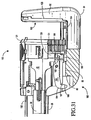
- the end effector 80 also includes a safety lockout mechanism 180 (best seen in FIGURE 31 ) for preventing the firing of a previously fired cartridge module 120.
- the cartridge module 120 contains a cartridge housing 121 coupled to an anvil 122.
- the cartridge module 120 also includes a retaining pin 125, a knife 126, a removable retainer 160, a tissue contacting surface 127 which displays a plurality of staple-containing slots 128 in staggered formation in one or more rows (that is, staple lines) on either side of the knife 126. Staples (not shown) are fired from the cartridge housing 121 against staple-forming surface 129 of the anvil 122 that faces the tissue-contacting surface 127 of the cartridge housing 121.
- the present linear surgical stapler 20 is designed as a multiple firing device with a replaceable cartridge module 120.
- a replaceable cartridge module 120 it should be understood that many of the underlying concepts of the present invention may be equally applied in single firing devices without departing from the present invention.
- the supporting structure 81 of the end effector 80 is respectively attached to the right and left handle plates 34, 35, by a shoulder rivet 82 and posts 83 which extend from the supporting structure 81 into receiving holes in the handle plates 34, 35.
- the supporting structure 81 is formed via a single piece construction. More specifically, the supporting structure 81 is formed by extrusion, for example, of aluminum, with subsequent machining to create the supporting structure 81 disclosed in accordance with the present invention. By constructing the supporting structure 81 in this manner, multiple parts are not required and the associated cost of manufacture and assembly is substantially reduced. In addition, it is believed the unitary structure of the supporting structure 81 enhances the overall stability of the present linear surgical stapler 20.
- the unitary extruded structure of the supporting structure 81 provides for a reduction in weight, easier sterilization since cobalt irradiation will effectively penetrate the extruded aluminum and less trauma to tissue based upon the smooth outer surface achieved via extrusion.
- the handle 21 of the linear surgical stapler 20 includes a hand grip 24 which the surgeon grasps with the palm of his hand (see FIGURES 2 to 5 ).
- the hand grip 24 is composed of a right hand shroud handle 25 (see FIGURE 1 ) and a left hand shroud handle (the left hand shroud handle is not shown in FIGURE 1 ).
- Pivotally extending from the underside of the handle 21 are a closure trigger 26 and a firing trigger 27.
- the linear surgical stapler 20 illustrated in FIGURE 1 is shown with the closure and firing triggers 26, 27 in their unactuated positions and with a cartridge module 120 inserted and the retainer 160 removed. Consequently, the cartridge housing 121 is spaced from the anvil 122 for the placement of tissue between the cartridge housing 121 and the anvil 122.
- the handle 21 of the linear surgical stapler 20 contains a tissue retaining pin actuation mechanism 100.
- the tissue retaining pin actuation mechanism 100 includes a saddle shaped slide 101 positioned on the top surface of the handle 21. Manual movement of the slide 101 results in distal movement of the push rod 102.
- the push rod 102 is coupled to the retaining pin 125 of the cartridge module 120. The distal movement or proximal retraction of the push rod 102 results in corresponding movement of the retaining pin 125.
- the retaining pin actuation mechanism 100 is also releasably coupled to the closure trigger 26 within the handle 21 such that actuation of the closure trigger 26 will result in automatic distal movement of the retaining pin 125 if it has not already been manually moved to its most proximal position.
- FIGURES 2 to 5 there is illustrated what happens when the cartridge module 120 is loaded and the closure and firing triggers 26, 27 are sequentially squeezed toward the hand grip 24 to actuate the end effector 80 of the linear surgical stapler 20.
- the linear surgical stapler 20 is loaded with the cartridge module 120, as shown in FIGURE 2 , and the retainer 160 is removed.
- the linear surgical stapler 20 is now ready to receive tissue as shown in FIGURE 1 .
- the cartridge housing 121 moves from its fully opened position to an intermediate position between the open and closed positions as discussed below in greater detail.
- the tissue retaining pin actuation mechanism 100 moves the retaining pin 125 forward from the cartridge housing 121 through an opening in the anvil 122. In this position, tissue which has been placed between the cartridge housing 121 and the anvil 122 can be properly positioned, and the retention of the tissue between the cartridge housing 121 and the anvil 122 is assured. Therefore, when the closure trigger 26 has been actuated to its intermediate position, the cartridge housing 121 and anvil 122 are correspondingly positioned in their tissue retaining positions.
- the closure trigger 26 When the closure trigger 26 is fully squeezed so that it is adjacent the forward end of the hand grip 24, as illustrated in FIGURE 4 , the tissue contacting surface 127 of the cartridge housing 121 and the staple-forming surface 129 of the anvil 122 are adjacent to each other, and the properly positioned and retained tissue is consequently fully clamped. Additionally, the firing trigger 27 has rotated counterclockwise toward the handgrip 24 to enable the surgeon to grasp the firing trigger 27 for the firing of staples. Accordingly, the firing trigger 27 is now in position for the surgeon to squeeze it to staple and cut the tissue. When the firing trigger 27 has been fully squeezed to fire the staples, as shown in FIGURE 5 , the firing trigger 27 rests in near proximity to the closure trigger 26.
- the present cartridge module 120 provides a cutting and sealing mechanism for utilization within the linear surgical stapler 20 wherein the stapling and cutting functions operate in the same direction during device actuation.
- the present cartridge module 120 is particularly adapted for use in conjunction with linear surgical stapling devices, the concepts of the present cartridge module 120 may be applied to other surgical devices without departing from the present invention.
- the present cartridge module 120 provides that the knife 126 be utilized in conjunction with a corresponding washer 123 during the cutting process.
- the present cartridge module 120 ensures that multiple firings of the linear surgical stapler 20 will not compromising cutting performance.
- Enhanced performance is further provided by positioning the anvil 122 and the cartridge housing 121 parallel such that they move relative to each other with the facing surfaces of the anvil 122 and the cartridge housing 121 maintained in a parallel orientation. This provides for an even distribution of pressure across the tissue, preventing squeezing of the tissue in a manner which might bunch the tissue and force portions of the tissue out of the desired spaced defined between the anvil 122 and the cartridge housing 121.
- the cartridge module 120 includes a cartridge housing 121 that contains a plurality of staples (not shown) positioned in staple-containing slots 128. Immediately behind the staples is disposed a driver 131 which is disposed to push the staples out of the staple slots 128. A knife holder 130 is disposed immediately proximal of the driver 131 in the cartridge housing 121. The knife holder 130 contains a slot 172 and ledge 173 for interaction with a knife retractor hook 45 (see FIG. 37 ) the function of which will be discussed below in greater. The knife holder 130 is attached to a knife 126 that extends distally from the knife holder 130 through a slot 200 in the driver 131 and through a slot 199 in the cartridge housing 121.
- the knife holder 130 has a detent post 138 that extends through a slot 137 in the cartridge housing 121.
- the knife holder detent post 138 is disposed to contact detent protrusion 139 of the cartridge slot 137 during the longitudinal travel of the knife 126 and the knife holder 130.
- the driver 131 has a detent post 140 that is disposed to contact proximal and distal detent protrusions 141,142, respectively, of the cartridge slot 137.
- the knife 126 and slots 199, 200 are positioned such that there is at least one row of staples on either side of the knife 126.
- two rows of staple slots 128 (and two rows of staples) are provided on each side of the slot 199 of the cartridge housing 121.
- the cartridge housing 121 contains two generally circular openings 143, 144 at either end of the knife slot 199.
- the general circular opening 143 at the base of the cartridge housing 121 is shaped and dimensioned for the passage of a guide pin 124 through the cartridge housing 121.
- the generally circular hole 144 at the top of the cartridge housing 121 is shaped and dimensioned for the passage of a retaining pin 125 through the cartridge housing 121.
- the staple slots 128 are arranged such that the staples laterally extend past the generally circular holes 143, 144.
- the anvil 122 includes a plastic washer 123 and a metallic staple-forming surface 129.
- the anvil 122 is disposed to maintain staple-forming surface 129 in a matching configuration.
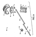
- the retaining pin 125 is connected to a coupler 133 by a circumferential slot 135 in the retaining pin 125 and a groove 134 in the coupler 133 (best seen in FIGURE 14 ).
- the coupler 133 is disposed within an arm 145 of the cartridge housing 121 and is held into the arm 145 by an end cap 146.
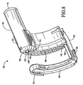
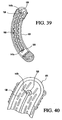
- the guide pin 124 and retaining pin 125 include respective slots 147a, 147b (best seen in FIGURES 8 , 9 , 36 , 39 and 40 ) into which the ends 126a, 126b of the knife 126 are disposed.
- the guide pin 124 proximal end 148 is connected to the proximal end 149 of the anvil 122.
- the distal end 150 of the guide pin 124 extends from the cartridge housing 121 and extends through a slot 151 of the anvil 122.
- a cutting washer 123 slips onto the anvil 122 by means of a groove 152 on the anvil 122 that fits under a tongue 153 on the washer 123.
- the opposite end 154 of the cutting washer 123 slips under the anvil arm 155 and is pinned to the anvil arm 155 by a pin 156. In this position, the cutting surface 157 of the washer 123 extends up through a slot 151 of the anvil 122.
- the assembly of the cutting washer 123 to the anvil 122 traps the guide pin 124 into the opening formed by the anvil slot 151 and the cutting surface 157, thereby, operatively connecting the anvil 122 to the cartridge housing 121.
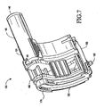
- the retainer 160 is attached to the cartridge module 120 as shown in FIGURE 7 to hold the components of the cartridge module 120 in a desired orientation until insertion into the end effector 80.
- the cartridge module 120 includes an anvil 122, or plate, having staple-forming surface 129 and a washer 123.
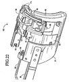
- the anvil 122 is supported by the distal end of the supporting structure 81 of the linear surgical stapler 20. That is, the anvil 122 of the present cartridge module 120 has its rearward surface supported by and the distal end of the supporting structure 81 formed as an integral part of the linear surgical stapler's supporting structure 81. More specifically, the washer 123 is in direct contact with the supporting structure 81 (see FIGURES 6 , 7 and 22 ). As forces are applied to the anvil 122, the washer 123 presses against the supporting structure 81.
- the cartridge module 120 in accordance with a preferred embodiment of the present invention includes a cartridge housing 121 in which the staples and knife 126 are housed for movement.
- the anvil 122 is directly linked to the cartridge housing 121 and forms an integral part of the cartridge module 120 as discussed above. In this way, the anvil 122 and the cartridge housing 121 form a complete cartridge module 120 which may be replaced as needed when a multiple-firing surgical stapling device is needed.
- Coupling members (discussed below in greater detail) extending from the cartridge module 120 couple the present cartridge module 120 to the end effector 80 of the supporting structure 81 of the linear surgical stapler 20.
- the cartridge module 120 is seated within the linear surgical stapler 20 with the anvil 122 sitting directly in front of the anvil support 82 of the supporting structure 81 of the linear surgical stapler 20.
- a retainer 160 is provided between the anvil 122 and the cartridge housing 121.
- the retainer 160 prevents undesired movement of the cartridge housing structure toward the anvil 122.
- the retainer 160 is selectively removable when the device is ready for use.
- an alternate embodiment of the integral housing structure/anvil cartridge module 120' is disclosed.
- the cartridge module 120' provides a cutting and sealing mechanism for utilization within a linear surgical stapler 20 wherein the stapling and cutting functions operate in the same direction during device actuation.
- the cartridge module 120' includes an anvil 122' having staple forming surfaces 129' and a washer 123'.
- the anvil 122' is supported by distal end of the support structure of the linear surgical stapler. That is, the anvil 122' of the present cartridge module 120' has its rearward surface supported by the supporting structure formed as an integral part of the linear surgical stapler's supporting structure.
- the anvil 122' is directly linked to the cartridge housing 121' structure and forms and integral part of the cartridge module 120'.
- An anvil arm 155' attaches the anvil 122' to the cartridge housing 121' of the cartridge module 120'. In this way, the anvil 122' and the cartridge housing 121' form a complete cartridge module 120' which may be replaced as needed within the multiple-firing linear surgical stapler.
- Attachment pins 119' extending from opposite ends of the cartridge module 120' couple the present cartridge module 120' to the supporting structure of the linear surgical stapler. In this way, the cartridge module 120' is seated within the linear surgical stapler with the anvil 122' sitting directly in front of the anvil support of the supporting structure of the linear surgical stapler.
- FIGURES 42 and 43 A further embodiment is disclosed with reference to FIGURES 42 and 43 .
- This embodiment includes an anvil 122' having only a washer 123" (the remaining portions of the anvil are formed as part of the supporting structure 8 1 "of the end effector 80"). As such, the washer 123" slides within a slot 136" formed in the supporting structure 81" to secure the cartridge module 120" to the end effector 80".
- the anvil 122" is directly linked to the cartridge housing 121" structure and forms and integral part of the cartridge module 120".
- An anvil arm 155" attaches the anvil 122" to the cartridge housing 121" of the cartridge module 120".
- Attachment pins 119" extending from opposite ends of the cartridge module 120" couple the present cartridge module 120" to the supporting structure 81" of the linear surgical stapler. Movement of the cartridge housing 121" distally along the linear surgical stapler toward the anvil 122" is facilitated by the provision a track 118" in which the cartridge housing 121" rides as it is moved toward the anvil 122".
- the replaceable parts making up the anvil and cartridge housing are package together as a complete replacement head, or cartridge module.
- Each replacement head incorporates a support bridge that holds the cartridge housing to the washer such that the washer is integrally formed with the cutting elements.
- Each replacement head includes a retainer that supports the parts during shipping and also protects the staples from being dislodged. The head is easily attachable and detachable from the primary support structure of the linear surgical stapler.
- the present cartridge module incorporating and anvil with staple forming surfaces and a washer is advantageous over prior devices in that it provides a cutting mechanism permitting multiple firings without compromising cutting performance. This is achieved by providing a new anvil with a new washer and anvil pockets for each firing.
- the present cartridge module is lower costs than single-fire devices since only the replacement head with the anvil needs to be replaced upon utilization of the device.
- the retainer 160 has a groove 161 that is disposed around a protrusion 159 of the cartridge housing 121.
- the retainer 160 contains a resilient inner spring arm 162 that is disposed for reciprocating movement within the retainer 160.
- the retainer 160 includes containment slots 163 which extend partially around the guide pin 124.
- the spring arm 162 includes containment slots 164 which extend partially around the guide pin 124, but are configured to face in an opposing direction to the containment slots 163.
- the retainer 160 is positioned onto the cartridge module 120 such that the containment slots 163, 164 surround the guide pin 124 and trap the retainer 160 onto the cartridge module 120.
- the spring arm 162 includes a disengagement tab 165 which extends down from the retainer 160 below the anvil arm 155. As such, the retainer 160 is not easily removed from the cartridge module 120 until the cartridge module 120 is properly seated within the end effector 80. Upon proper seating of the cartridge module 120 within the end effector 80, the disengagement tab 165 engages the end effector 80 for release of the retainer 160.
- the linear surgical stapler 20 includes an elongated closure member 28, with a generally U shaped cross section, extending from the handle 21 into the surgical fastening assembly of the end effector 80.
- the closure member 28 is a molded plastic member shaped for movement and functionality in accordance with the present invention.
- the closure member may be made from extruded aluminum with the final features machined into place. While an extruded aluminum closure member might not be as easy to manufacture as the plastic component, it would still have the same advantages (i.e., elimination of components, easier to assemble, lower weight, easier to sterilize).
- the distal portion of the closure member 28 passes through the walls 84 of the supporting structure 81. The distal end is disposed to receive and retain the cartridge housing 121 of the cartridge module 120.
- the central portion of the closure member 28 is positioned between the right and left handle plates 34,35, respectively.
- Right and left hand closure links 36, 37, respectively, are pivotally attached at the right and left proximal ends of the closure member 28 by a first integral closure link pin 38.
- the closure links 36, 37 are pivotally attached to a second integral closure link pin 39.
- the second integral closure link pin 39 connects the closure links 36, 37 to a slotted closure arm link 40.
- the slotted closure arm link 40 is pivotally mounted to the handle plates 34, 35 of the linear surgical stapler 20 at a closure trigger pivot pin 41.
- the closure trigger 26 descends from the slotted closure arm link 40 for pivotal rotation about the closure trigger pivot pin 41 toward and away from the handgrip 24.
- a closure spring 42 housed within the hand grip 24 of the handle 21 is secured to the slotted closure arm link 40 to provide a desired resistance when the surgeon squeezes the closure trigger 26 toward the handle grip 24, and to bias the closure trigger 26 toward the open position.
- the handle 21 contains a saddle shaped slide 101 mounted on top of the handle 21 for linear motion.
- the slide 101 is connected to a post 103 that extends outward from a push rod driver 104 through slots 105 (see FIGURE 2 ) in the handle 21.
- the push rod driver 104 is restrained for longitudinal movement along the long axis of the linear surgical stapler 20 by slots 105.
- the push rod driver 104 is connected to the push rod 102 by a circumferential groove 107 on the push rod 102 that snaps into a slot 108 of the push rod driver 104.
- the distal end of the push rod 102 contains a circumferential groove 109 that interconnects with a groove 132 in the proximal end of the coupler 133 of the cartridge module 120 (best seen in FIGURE 22 ).
- the distal end of the coupler 133 contains a groove 134 for interconnecting with a circumferential slot 135 on the retaining pin 125.
- the closure member 28 contains posts 29 which extend laterally on both sides of the closure member 28 inside the handle 21. These posts 29 slidably connect to an L-shaped slot 110 of a yoke 111.
- the yoke 111 is pivotally mounted to the handle 21 by a pivot pin 112 on the yoke 111.
- the yoke 111 contains cam pins 113 positioned to push camming surfaces 114 on the push rod driver 104.
- the firing transmission assembly has an elongated firing bar 43 extending from the handle 21 into the surgical fastening assembly of the end effector 80.
- the firing bar 43 is positioned within the U shaped cross section of the closure member 28.
- the distal end of the firing bar 43 extends into the cartridge housing 121 and is positioned just proximally of the knife holder 130 and driver 131.
- the distal end of the firing bar 43 is attached to a knife retractor 44 that has a knife retraction hook 45.
- the firing bar 43 has a rectangular receiving slot 46 in that portion of the firing bar 43 that is housed within the handle 21 (see FIGURE 13 ).
- the first integral closure link pin 38 extends through the receiving slot 46.
- the firing bar 43 also has a proximal end section 47.
- the underside of the proximal end section 47 of the firing bar 43 has a sliding surface 48.
- the proximal end section 47 also has a terminal side engagement surface 49 extending from the sliding surface 48.
- the firing trigger 27 is pivotally mounted to the handle plates 34, 35 by a firing trigger pivot pin 50 spaced from the closure trigger pivot pin 41 so that each of the pivot pins pivot about mutually independent axes.
- the firing trigger 27 includes an arcuate firing trigger link 51 extending from the firing trigger 27 at the firing trigger pivot pin 50 to an apex 52 which rests on the sliding surface 48 of the proximal end section 47 of the firing bar 43.
- the firing trigger 27 is attached to first and second firing trigger spring arms 53, 54, respectively.
- the firing trigger spring arms 53, 54 support a torsion spring (not shown) on the right half of the firing trigger 43.
- a firing bar return spring 55 is secured to the underside of the firing bar 43 at that portion of the firing bar 43 within the handle 21 to bias the firing bar 43 toward its unactuated position.
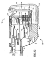
- the mechanism which defines an intermediate closure detent position and the release of the closure trigger 26 from an actuated position to its original unactuated position will now be described in connection with FIGURE 1 in combination with FIGURES 13-20 .
- the top side of the slotted closure arm link 40 has a clamp sliding surface 56 that displays an intermediate detent 57 and a closure detent 58.
- a release pall 59 slides on the clamp sliding surface 56 and may engage the intermediate and closure detents 57, 58.
- the release pall 59 has a laterally extending pall lug 60 (best seen in FIGURE 1 ) at its distal end.
- the release pall 59 is located within the handle 21, and it is integrally attached to a release button 61 situated exteriorly of the handle 21.
- the release button 61 has a thumb rest 62, and the release button 61 is pivotally attached to the handle 21 by a release trunnion 63.
- the release button 61 is biased outwardly from the handle 21 and, therefore, the release pall 59 is biased downwardly toward the clamp sliding surface 56 by a release spring 64 which is mounted to the handle 21 by a spring retention pin 65 and mounted to the release button 61 by a button spring post 66.
- the slotted closure arm link 40 has an arcuate recess 67 located between the intermediate and closure detents 57, 58. Sitting within this arcuate recess 67 for rotational movement are a left hand toggle 68 integrally connected to a right hand toggle (the right hand toggle is not shown).
- Each toggle 68 has a toggle arm 69 that is engageable with the pall lug 60.
- the pall lug 60 has a concave proximal surface 70 to provide clearance between the toggle arm 69 and the pall lug 60.
- the lockout mechanism 180 contains a lockout lever 181 that is pivotally mounted to the distal end 30 of the closure member 28 by a pin 182.
- the lockout lever 181 is spring biased down toward the base of supporting structure 81 by a spring (not shown).
- the lockout lever 181 contains a proximal and distal end 184, 185, respectively.
- the proximal end 184 has a cam surface 186 and locking groove 187.
- the supporting structure 81 of the end effector 80 contains a ledge 85 that is disposed to interact with locking groove 187 when the lockout mechanism 180 is engaged.
- the supporting structure 81 contains a base surface 86 between walls 84. The base surface 86 is disposed to interact with cam surface 186 when the lockout lever 181 is not engaged.
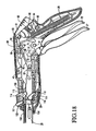
- the operation of loading the cartridge module 120, the closure mechanism, the retaining pin mechanism, the firing transmission assembly, the intermediate and closure detents 57, 58, the release mechanism, and the lockout mechanism 180 will now be described. Referring to FIGURES 7 to 12 and FIGURES 21 to 28 the loading of the cartridge module 120 into the tissue end effector 80 is described.
- the cartridge module 120 is shaped and dimensioned for selective insertion and removal from the tissue end effector 80 of the linear surgical stapler 20.
- the retainer 160 Prior to insertion of the cartridge module 120 into the end effector 80 of the linear surgical stapler 20, as seen in FIGURE 7 , the retainer 160 can not easily be removed from the cartridge module 120 as the groove 161 is disposed around the protrusion 159 at the top end of the retainer 160 preventing disconnection. Further, the containment slots 163, 164 of the retainer are disposed around the guide pin 124 at the bottom of the retainer 160 preventing disconnection as shown in FIGURE 25 .
- the attached retainer 160 provides support to the structure of the cartridge module 120 and an extended surface area for gripping, both features making loading easier.
- the retainer 160 also prevents staples from dislodging from the cartridge housing 121 during casual handling and prevents the knife 126 from accidental exposure during casual handling.
- Knife 126 movement and staple movement are further resisted prior to loading and during loading by a series of detents.
- detent post 138 on the knife holder 130 is prevented from proximal and distal movement by the detent protrusion 139 on the cartridge housing slot 137.
- the driver 131 is prevented from distal movement due to casual handling and during loading of the cartridge module 120 into the linear surgical stapler 20 by the interaction of the detent post 140 and the detent protrusion 141 on the cartridge housing slot 137.
- the cartridge module 120 is loaded into the tissue effector 80 such that the cartridge housing 121 slips into the distal end 30 of the closure member 28 as seen in FIGURES 21 to 24 .
- Walls 31a and 31b on the closure member 28 slip into slots 170a, 170b of the cartridge housing 121 during loading.
- tabs 174 (See FIGURE 8 ) slip into groove 88 of the U-shaped supporting structure 81.
- the tabs are U-shaped and fit over the grooves 88 along the supporting structure to securely and accurately couple the cartridge module 120 to the end effector 80. Loading of the cartridge module 120 is completed when the detents 171 snap onto the detent groove 32 of the closure member distal end 30, as shown in FIGURES 21 to 24 .
- the cartridge module 120 is fully loaded and the proximal groove 132 of the coupler 133 has engaged the distal circumferential groove 109 of the push rod 102 such that the retaining pin 125 in the cartridge module 120 has been connected to the retaining pin advancement mechanism 100.
- the slot 172 of knife holder 131 engages the knife retraction hook 45 during loading such that the hook 45 has engaged the retraction ledge 173 on the knife holder 130 at the completion of the cartridge module 120 loading.
- a post 188 positioned on driver 131 contacts the distal end 185 of the lockout lever 181 (see FIGURE 31 ). This contact pivots the lockout lever 181 about the lockout lever pin 182 to a position such that the camming surface 186 is horizontally aligned with the base surface 86 of the U shaped supporting structure 81.
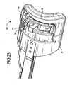
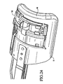
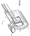
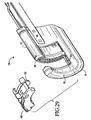
- the retainer 160 can now be removed from the end effector 80. Specifically, completion of loading the cartridge module 120 causes the disengagement tab 165 to contact the supporting structure 81 (See FIGURE 23 ), resulting in an upward movement of the spring arm 162 when the cartridge module 120 is fully loaded as in FIGURE 24 . This upward movement displaces containment slots 164 upward such that the guide pin 124 is no longer contained (see FIGURES 25 and 26 ). Referring now to FIGS 27 to 29 , a removal force applied to the thumb pad 166 results in the retainer 160 pivoting outward about protrusion 159 until the groove 161 is able to slip off protrusion 159. Removal of the retainer 160 allows for the loaded linear surgical stapler 20 to be utilized.
- the closure trigger 26 has been partially squeezed from its open, unactuated position illustrated in FIGURES 1 and 13 .
- the closure trigger 26 pivots about the closure trigger pivot pin 41 in a counterclockwise direction toward the handgrip 24.
- the slotted closure arm link 40 and closure plate closure links 36, 37 move forwardly, consequently moving the closure member 28 and firing bar 43 distally.
- the pall lug 60 of the release pall 59 slides on the clamp sliding surface 56.
- the pall lug 60 engages the distal ends of the toggle arms 69 of the toggles 68, and consequently pivots the toggles 68 in a clockwise direction.
- the pall lug 60 of the release pall 59 will eventually lodge into the intermediate detent 57.
- the closure spring 42 is incapable of returning the closure trigger 26 to its original, unactuated position.
- the closure trigger 26 is now in its intermediate, partially closed position, to properly position and retain tissue between the cartridge housing 121 and anvil 122, as shown in FIGURE 15 .
- the apex 52 of the arcuate firing trigger link 51 slides on the sliding surface 48 of the proximal end section 47 of the firing bar 43.
- the retaining pin mechanism 100 is activated. Forward movement of the closure member 28 moves the integral posts 29 distally. The posts 29 contact the L-shaped slot 110 of the yoke 111. Hence, distal movement of the posts 29 cam the L-shaped slot 110 causing the yoke to pivot around pins 112. The rotation brings bearing posts 113 on the yoke 111 into contact with camming surfaces 114 on the push rod driver 104. Further rotational movement of the yoke 111 causes bearing posts 113 to move the push rod driver 104 distally through camming contact on surfaces 114. The push rod driver 104 contacts the push rod 102, moving the push rod 102 distally.
- the push rod 102 moves the coupler 133 and retaining pin 125 distally.
- Completion of the closing stroke to the intermediate detent 57 position results in the retaining pin 125 moving distally through the hole 144 of the cartridge housing 121, the slot of the anvil 151, the hole in the washer 170 and into the hole 89 (not shown) in the supporting structure 81.
- Tissue which was disposed between the contact surface 127 of the cartridge housing 121 and the anvil 122, is now trapped between retaining pin 125 and the guide pin 124.
- the closing stroke from the open to the intermediate detent 57 position moves the lockout lever 181 distally as it is attached to closure member 28 by the pin 182 as shown in FIGURE 31 (open) and FIGURE 32 (intermediate position).
- Distal movement of the lockout lever 181 causes the camming surface 186 to contact the lockout ledge 85 of the support 81, resulting in the lockout lever 181 rotating clockwise and coming to slidable contact with base surface 86 of supporting structure 81.
- the distal end 185 of the lockout lever 181 has rotated away from post 188 on driver 131.
- the firing trigger 27 is moving into a position where it can continue to move the firing bar 43 distally to fire staples after the tissue has been fully clamped.
- the firing trigger 27 begins to pivotally rotate in a counterclockwise direction toward the hand grip 24 in response to the action of a torsion spring on the right hand side of the trigger 27 (torsion spring not shown).
- the firing trigger 27 pivots independently of the pivotal movement of the closure trigger 26, but its pivotal rotation is blocked until the firing bar 43 has moved distally to enable engagement of the firing trigger link 51 with the terminal engagement surface of the firing bar 43.
- FIGURE 17 when the closure trigger 47 has been fully squeezed and it is adjacent the handgrip 24, the pall lug 60 at the distal end of the release pall lodge 59 into the closure detent 58.
- the closure detent 58 position the tissue has been fully clamped between the cartridge housing 121 and anvil 122, and the closure spring 42 is incapable of returning the closure trigger 26 to its original position. Therefore, the closure trigger 26 is retained in the position shown in FIGURE 4 .
- the firing trigger 27 continues to rotate counterclockwise by the action of the torsion firing bar return spring 55 until the firing trigger 27 is in a relatively vertical orientation with respect to the handle 21 of the linear surgical stapler 20.
- the apex 52 of the arcuate firing trigger link 51 has fully engaged the engagement surface of the proximal end section 47 of the firing bar 43 and, therefore, the firing trigger 27 is in a position to further move the firing bar 43 distally to fire staples into the tissue.
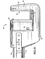
- the staple pockets 128 of the cartridge housing 121 are aligned with the staple-forming surface 129 of the anvil 122 as shown in FIGURE 33 .
- the retaining pin 125 has aligned the top of the anvil 122 and the cartridge housing 121 and the guide pin 124 has aligned the bottom of the cartridge housing 121 with the bottom of the anvil 122.
- the firing trigger 27 can be squeezed to pivotally rotate it toward the hand grip 24 until it is positioned adjacent the closure trigger 26.
- the firing bar 43 moves distally, contacts the knife holder 130.
- the resulting distal movement of the knife holder 130 results in contact with the knife 126 and driver 131.
- Distal movement of the driver 131 results in the staples (not shown) to be distally advanced into the staple forming surfaces 129 of the anvil 122 resulting in staple formation of a generally B shape.
- the knife 126 distally advances in slots 147 of the guide pin 124 and the retaining pin 125 in conjunction with staple formation. These slots 147 guide the knife 126 onto the cutting surface 157 of cutting washer 123 resulting in the transection of any tissue caught between.
- the user can manually retract the cutting system by pulling clockwise on the firing trigger 27.
- the manual clockwise movement causes the arcuate firing trigger link 51 to rotate clockwise until it strikes a firing bar retraction tab 71 on the proximal end 47 of the firing bar 43.
- the contact between the clockwise moving arcuate firing trigger link 51 and the firing bar retraction tab 71 cause the firing bar 43 to retract proximally and return to the position shown in FIGURE 17 .
- this safety feature allows for the user to retract the cutting mechanism to a safe position and return the firing system to a position that would allow the linear surgical stapler 20 to be opened as will now be described.
- the release pall 59 pivots about the release trunnion 63 in a clockwise direction to dislodge the pall lug 60 from the closure detent 58 position. As it is dislodged, the pall lug 60 rides on the toggle arms 69 to bypass the intermediate detent position 57 on clamp link 40. In this manner, the closure and firing triggers 26, 27 can return to their original, unactuated positions in response to the bias created from the closure spring 42 and firing bar return spring 55.
- the retaining pin mechanism 100 After release of the device back to the open position shown in FIGURES 1 and 2 , the retaining pin mechanism 100 must be manually retracted by pulling proximally on saddle 101. The retraction causes the retaining pin 125 to retract back into the cartridge housing 121. At the completion of the manual retraction the fired cartridge module 120 can be unloaded and replaced with a new cartridge module 120.
Abstract
Description
- The present invention relates to a surgical stapling and cutting instrument adapted for use in the diagnosis and therapy of pathologies treated by stapled resection. More particularly, the invention relates to a replaceable cartridge module utilized in conjunction with a surgical stapling and cutting instrument. The replaceable cartridge module including both a cartridge housing, for staples and a knife, and an anvil.
- Within the field of surgery, the need to surgically seal tissue and to cut tissue is quite commonplace. Sealing of tissue maybe accomplished by numerous sealing devices, for example, surgical staplers. Cutting of tissue may be accomplished by numerous cutting devices, for example, scalpels and surgical scissors. Stapling and cutting of tissue in several steps during the surgical procedure adds time to such procedures. In order to reduce procedural steps and ultimately the time necessary for various surgical procedures, instruments have been developed which simultaneously apply staples and cut desired tissue. As those skilled in the art will certainly appreciate, it is desirable to provide stapling and cutting instruments capable of performing multiple stapling and cutting routines during a single procedure.
- Some current surgical instruments provide stapling and cutting mechanisms that operate in the same direction during device actuation, or firing. For instance, staple formation and tissue cutting occur along the same plane on the tissue. These instruments generally utilize an anvil, which holds staple pockets (or staple forming surfaces) and a washer, and a housing assembly, which holds staples and a knife. In these prior instruments, the anvil is generally a permanent element of the instrument and the housing assembly is either a permanent element (single-fire device) or a reloadable element (multiple-fire device). Tissue is captured between the anvil and the housing assembly of the device. Actuation of the instrument moves the staples from the housing assembly toward the anvil. The staples puncture the captured tissue and then contact staple pockets on the anvil, which form the staples into desired shapes to seal the tissue. In conjunction with the staple formation, actuation of the instrument also moves the knife from the housing assembly toward the anvil. The knife pushes the tissue toward the anvil and, upon contact with the knife and the washer on the anvil, cutting of the tissue is facilitated. The washer functions in a manner similar to cutting on a cutting board.
- The washer is generally made of a resilient material and is a permanent element of the anvil. The knife is either a permanent element that actuates within the housing assembly or a reloadable element with the housing assembly. For single-fire instruments, the washer and knife are discarded with the complete instrument after firing. Single-fire instruments present higher associated costs since a new instrument is needed for subsequent firings. For multiple-firing instruments, the housing assembly is discarded and a new housing assembly is reloaded while the anvil with accompanying washer is reused for subsequent filings.
- Since the washer is generally manufactured out of a plastic material and the knife is manufactured out of a metallic material, multiple firings into the same washer often causes degradation of the washer. This may hinder cutting performance and is consequently undesirable.
-
EP-A-0373823 discloses a surgical fastener cartridge comprising an anvil. - As a result, it is desirable to provide a surgical stapling and cutting instrument adapted for effectively and efficiently permitting multiple cuts with corresponding staples during a single procedure. The present invention provides such a surgical stapling and cutting instrument including a replaceable cartridge module having a cartridge housing and an anvil.
-
-
Figure 1 is a perspective view of the linear surgical stapler in accordance with the present invention. -
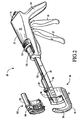
Figure 2 is perspective view of the linear surgical stapler with the cartridge module removed. -
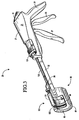
Figure 3 is a perspective view of the linear surgical stapler with the cartridge housing moved to an intermediate position. -
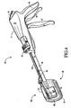
Figure 4 is a perspective view of the linear surgical stapler with the cartridge housing moved to a closed position. -
Figure 5 is a perspective view of the linear surgical stapler with the firing trigger in a firing position. -
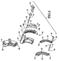
Figure 6 is an exploded view of the cartridge module. -
Figure 7 is a front perspective view of the cartridge module with the retainer secured thereto. -
Figure 8 is a front perspective view of the cartridge module with the retainer removed. -
Figure 9 is a rear perspective view of the cartridge module showing the cartridge housing slot in substantial detail. -
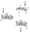
Figures 10,11 and 12 show the assembly of the retainer. -
Figure 13 is a partial cross-sectional view of the linear surgical stapler in an unactuated orientation. -
Figure 14 is a exploded view of the pin actuation mechanism. -
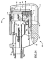
Figure 15 is a partial cross sectional view of the linear surgical stapler with the closure trigger slightly retracted. -
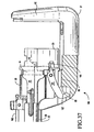
Figure 16 is a partial cross sectional view of the linear surgical stapler with the closure trigger nearly fully retracted. -
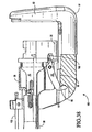
Figure 17 is a partial cross sectional view of the linear surgical stapler with the closure trigger fully retracted. -
Figure 18 is a partial cross sectional view of the linear surgical stapler with the firing trigger and closure trigger fully retracted. -
Figure 19 is partial cross sectional view of the linear surgical stapler after the surgeon depresses the release button. -
Figure 20 is a partial cross sectional view of the linear surgical stapler upon release of the closure and firing triggers without returning to an intermediate detent position. -
Figure 21 -29 show the insertion of a cartridge module and the removal of the retainer. -
Figures 30-38 show the various steps involved in the actuation of the present linear surgical stapler. -
Figures 39 and 40 are detailed front views of the cartridge housing. -
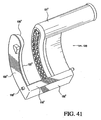
Figures 41 ,42 and 43 disclose alternate embodiments of the cartridge module. - The detailed embodiments of the present invention are disclosed herein. It should be understood, however, that the disclosed embodiments are merely exemplary of the invention, which may be embodied in various forms. Therefore, the details disclosed herein are not to be interpreted as limiting, but merely as the basis for teaching one skilled in the art how to make and/or use the invention.
- With reference to the various figures, the present invention is directed to a
surgical instrument 20 adapted for stapling and cutting tissue in a highly controlled manner. Theinstrument 20 generally includes a frame having a proximal end and a distal end, with ahandle 21 positioned at the proximal end and anend effector 80 positioned at the distal end. Theend effector 80 includes a U-shaped supportingstructure 81 shaped and dimensioned for selectively receiving acartridge module 120 containing a plurality of surgical fasteners and a knife. The surgical instrument further includes a firing mechanism associated with theend effector 80 and thecartridge module 120 for selective actuation of the surgical fasteners andknife 126. Finally, thecartridge module 120 includes acartridge housing 121 in which the surgical fasteners and knife are housed and ananvil 122 shaped and dimensioned for engagement with the surgical fasteners and knife to facilitate cutting and stapling. Thecartridge housing 121 andanvil 122 are relatively movable between a first spaced apart position and a second position in close approximation with one another. - Referring to
FIGURE 1 in combination withFIGURES 2 to 5 , there is shown a surgical stapling and cutting instrument, in particular, a linearsurgical stapler 20 which is designed to staple and cut tissue. The linearsurgical stapler 20 has ahandle 21 at a first proximal end and anend effector 80 at an opposite distal end. Theend effector 80 is curved in accordance with a preferred embodiment of the present invention. Right and left hand structural plates (often called "handle plates") 34, 35, respectively, connect thehandle 21 to theend effector 80 of the instrument (the left hand handle plate is not shown inFIGURE 1 ). Thehandle 21 has aright hand shroud 22 coupled to a left hand shroud (the left hand shroud is not shown inFIGURE 1 ). Thehandle 21 also has abody portion 23 to grip and maneuver the linear surgical stapler 20 (seeFIGURES 2 to 5 ). - The
end effector 80 is a surgical fastening assembly that includes a cartridge module 120 (seeFIGURES 6 to 9 ) and a U-shaped supportingstructure 81. Thedistal end 30 of aclosure member 28 is disposed to receive thecartridge module 120. Theend effector 80 also includes a safety lockout mechanism 180 (best seen inFIGURE 31 ) for preventing the firing of a previously firedcartridge module 120. Thecartridge module 120 contains acartridge housing 121 coupled to ananvil 122. Thecartridge module 120 also includes a retainingpin 125, aknife 126, aremovable retainer 160, atissue contacting surface 127 which displays a plurality of staple-containingslots 128 in staggered formation in one or more rows (that is, staple lines) on either side of theknife 126. Staples (not shown) are fired from thecartridge housing 121 against staple-formingsurface 129 of theanvil 122 that faces the tissue-contactingsurface 127 of thecartridge housing 121. - As will become apparent based upon the following disclosure, the present linear
surgical stapler 20 is designed as a multiple firing device with areplaceable cartridge module 120. However, it should be understood that many of the underlying concepts of the present invention may be equally applied in single firing devices without departing from the present invention. - The supporting
structure 81 of theend effector 80 is respectively attached to the right and lefthandle plates shoulder rivet 82 andposts 83 which extend from the supportingstructure 81 into receiving holes in thehandle plates structure 81 is formed via a single piece construction. More specifically, the supportingstructure 81 is formed by extrusion, for example, of aluminum, with subsequent machining to create the supportingstructure 81 disclosed in accordance with the present invention. By constructing the supportingstructure 81 in this manner, multiple parts are not required and the associated cost of manufacture and assembly is substantially reduced. In addition, it is believed the unitary structure of the supportingstructure 81 enhances the overall stability of the present linearsurgical stapler 20. In addition, the unitary extruded structure of the supportingstructure 81 provides for a reduction in weight, easier sterilization since cobalt irradiation will effectively penetrate the extruded aluminum and less trauma to tissue based upon the smooth outer surface achieved via extrusion. - The
handle 21 of the linearsurgical stapler 20 includes ahand grip 24 which the surgeon grasps with the palm of his hand (seeFIGURES 2 to 5 ). Thehand grip 24 is composed of a right hand shroud handle 25 (seeFIGURE 1 ) and a left hand shroud handle (the left hand shroud handle is not shown inFIGURE 1 ). Pivotally extending from the underside of thehandle 21 are aclosure trigger 26 and a firingtrigger 27. The linearsurgical stapler 20 illustrated inFIGURE 1 is shown with the closure and firing triggers 26, 27 in their unactuated positions and with acartridge module 120 inserted and theretainer 160 removed. Consequently, thecartridge housing 121 is spaced from theanvil 122 for the placement of tissue between thecartridge housing 121 and theanvil 122. - The
handle 21 of the linearsurgical stapler 20 contains a tissue retainingpin actuation mechanism 100. The tissue retainingpin actuation mechanism 100 includes a saddle shapedslide 101 positioned on the top surface of thehandle 21. Manual movement of theslide 101 results in distal movement of thepush rod 102. Thepush rod 102 is coupled to the retainingpin 125 of thecartridge module 120. The distal movement or proximal retraction of thepush rod 102 results in corresponding movement of the retainingpin 125. The retainingpin actuation mechanism 100 is also releasably coupled to theclosure trigger 26 within thehandle 21 such that actuation of theclosure trigger 26 will result in automatic distal movement of the retainingpin 125 if it has not already been manually moved to its most proximal position. - Referring briefly to
FIGURES 2 to 5 , there is illustrated what happens when thecartridge module 120 is loaded and the closure and firing triggers 26, 27 are sequentially squeezed toward thehand grip 24 to actuate theend effector 80 of the linearsurgical stapler 20. The linearsurgical stapler 20 is loaded with thecartridge module 120, as shown inFIGURE 2 , and theretainer 160 is removed. The linearsurgical stapler 20 is now ready to receive tissue as shown inFIGURE 1 . - When the
closure trigger 26 is partially squeezed to rest in its first detent position shown inFIGURE 3 , thecartridge housing 121 moves from its fully opened position to an intermediate position between the open and closed positions as discussed below in greater detail. Simultaneously, the tissue retainingpin actuation mechanism 100 moves the retainingpin 125 forward from thecartridge housing 121 through an opening in theanvil 122. In this position, tissue which has been placed between thecartridge housing 121 and theanvil 122 can be properly positioned, and the retention of the tissue between thecartridge housing 121 and theanvil 122 is assured. Therefore, when theclosure trigger 26 has been actuated to its intermediate position, thecartridge housing 121 andanvil 122 are correspondingly positioned in their tissue retaining positions. - When the
closure trigger 26 is fully squeezed so that it is adjacent the forward end of thehand grip 24, as illustrated inFIGURE 4 , thetissue contacting surface 127 of thecartridge housing 121 and the staple-formingsurface 129 of theanvil 122 are adjacent to each other, and the properly positioned and retained tissue is consequently fully clamped. Additionally, the firingtrigger 27 has rotated counterclockwise toward thehandgrip 24 to enable the surgeon to grasp the firingtrigger 27 for the firing of staples. Accordingly, the firingtrigger 27 is now in position for the surgeon to squeeze it to staple and cut the tissue. When the firingtrigger 27 has been fully squeezed to fire the staples, as shown inFIGURE 5 , the firingtrigger 27 rests in near proximity to theclosure trigger 26. - Referring now to
FIGURES 6 to 9 , a more detailed description of thecartridge module 120 is presented Thepresent cartridge module 120 provides a cutting and sealing mechanism for utilization within the linearsurgical stapler 20 wherein the stapling and cutting functions operate in the same direction during device actuation. Although thepresent cartridge module 120 is particularly adapted for use in conjunction with linear surgical stapling devices, the concepts of thepresent cartridge module 120 may be applied to other surgical devices without departing from the present invention. In particular, thepresent cartridge module 120 provides that theknife 126 be utilized in conjunction with acorresponding washer 123 during the cutting process. Thepresent cartridge module 120 ensures that multiple firings of the linearsurgical stapler 20 will not compromising cutting performance. This is accomplished by incorporating theanvil 122, in particular, thecutting washing 123, with thecartridge module 120. By combining thewasher 123 with thecartridge module 120, anew washer 123 is provided each time thecartridge module 120 is replaced, resulting in improved cutting performance. - Enhanced performance is further provided by positioning the
anvil 122 and thecartridge housing 121 parallel such that they move relative to each other with the facing surfaces of theanvil 122 and thecartridge housing 121 maintained in a parallel orientation. This provides for an even distribution of pressure across the tissue, preventing squeezing of the tissue in a manner which might bunch the tissue and force portions of the tissue out of the desired spaced defined between theanvil 122 and thecartridge housing 121. - More specifically, the
cartridge module 120 includes acartridge housing 121 that contains a plurality of staples (not shown) positioned in staple-containingslots 128. Immediately behind the staples is disposed adriver 131 which is disposed to push the staples out of thestaple slots 128. Aknife holder 130 is disposed immediately proximal of thedriver 131 in thecartridge housing 121. Theknife holder 130 contains aslot 172 andledge 173 for interaction with a knife retractor hook 45 (seeFIG. 37 ) the function of which will be discussed below in greater. Theknife holder 130 is attached to aknife 126 that extends distally from theknife holder 130 through aslot 200 in thedriver 131 and through aslot 199 in thecartridge housing 121. - The
knife holder 130 has adetent post 138 that extends through aslot 137 in thecartridge housing 121. The knifeholder detent post 138 is disposed to contactdetent protrusion 139 of thecartridge slot 137 during the longitudinal travel of theknife 126 and theknife holder 130. Similarly, thedriver 131 has adetent post 140 that is disposed to contact proximal and distal detent protrusions 141,142, respectively, of thecartridge slot 137. - The
knife 126 andslots knife 126. In accordance with a preferred embodiment of the present invention, two rows of staple slots 128 (and two rows of staples) are provided on each side of theslot 199 of thecartridge housing 121. - The
cartridge housing 121 contains two generallycircular openings knife slot 199. The generalcircular opening 143 at the base of thecartridge housing 121 is shaped and dimensioned for the passage of aguide pin 124 through thecartridge housing 121. The generallycircular hole 144 at the top of thecartridge housing 121 is shaped and dimensioned for the passage of a retainingpin 125 through thecartridge housing 121. Thestaple slots 128 are arranged such that the staples laterally extend past the generallycircular holes - In accordance with a preferred embodiment of the present invention, the
anvil 122 includes aplastic washer 123 and a metallic staple-formingsurface 129. Theanvil 122 is disposed to maintain staple-formingsurface 129 in a matching configuration. The retainingpin 125 is connected to acoupler 133 by acircumferential slot 135 in the retainingpin 125 and agroove 134 in the coupler 133 (best seen inFIGURE 14 ). Thecoupler 133 is disposed within anarm 145 of thecartridge housing 121 and is held into thearm 145 by anend cap 146. - The
guide pin 124 and retainingpin 125 includerespective slots FIGURES 8 ,9 ,36 ,39 and 40 ) into which theends knife 126 are disposed. Theguide pin 124proximal end 148 is connected to theproximal end 149 of theanvil 122. Thedistal end 150 of theguide pin 124 extends from thecartridge housing 121 and extends through aslot 151 of theanvil 122. A cuttingwasher 123 slips onto theanvil 122 by means of agroove 152 on theanvil 122 that fits under atongue 153 on thewasher 123. Theopposite end 154 of the cuttingwasher 123 slips under theanvil arm 155 and is pinned to theanvil arm 155 by apin 156. In this position, the cuttingsurface 157 of thewasher 123 extends up through aslot 151 of theanvil 122. The assembly of the cuttingwasher 123 to theanvil 122 traps theguide pin 124 into the opening formed by theanvil slot 151 and the cuttingsurface 157, thereby, operatively connecting theanvil 122 to thecartridge housing 121. Theretainer 160 is attached to thecartridge module 120 as shown inFIGURE 7 to hold the components of thecartridge module 120 in a desired orientation until insertion into theend effector 80. - As briefly discussed above, and in accordance with a preferred embodiment of the present invention, the
cartridge module 120 includes ananvil 122, or plate, having staple-formingsurface 129 and awasher 123. Theanvil 122 is supported by the distal end of the supportingstructure 81 of the linearsurgical stapler 20. That is, theanvil 122 of thepresent cartridge module 120 has its rearward surface supported by and the distal end of the supportingstructure 81 formed as an integral part of the linear surgical stapler's supportingstructure 81. More specifically, thewasher 123 is in direct contact with the supporting structure 81 (seeFIGURES 6 ,7 and22 ). As forces are applied to theanvil 122, thewasher 123 presses against the supportingstructure 81. - The
cartridge module 120 in accordance with a preferred embodiment of the present invention includes acartridge housing 121 in which the staples andknife 126 are housed for movement. Theanvil 122 is directly linked to thecartridge housing 121 and forms an integral part of thecartridge module 120 as discussed above. In this way, theanvil 122 and thecartridge housing 121 form acomplete cartridge module 120 which may be replaced as needed when a multiple-firing surgical stapling device is needed. - Coupling members (discussed below in greater detail) extending from the
cartridge module 120 couple thepresent cartridge module 120 to theend effector 80 of the supportingstructure 81 of the linearsurgical stapler 20. In this way, thecartridge module 120 is seated within the linearsurgical stapler 20 with theanvil 122 sitting directly in front of theanvil support 82 of the supportingstructure 81 of the linearsurgical stapler 20. - Movement of the
cartridge housing 121 distally along the long axis of the linearsurgical stapler 20 toward theanvil 122 is facilitated by the sliding engagement between thecartridge housing 121 and theanvil arm 155 which facilitates movement of thecartridge housing 121 relative to theanvil 122. Aretainer 160 is provided between theanvil 122 and thecartridge housing 121. Theretainer 160 prevents undesired movement of the cartridge housing structure toward theanvil 122. Theretainer 160 is selectively removable when the device is ready for use. - With reference to
FIGURE 41 , an alternate embodiment of the integral housing structure/anvil cartridge module 120' is disclosed. As with the prior embodiment, the cartridge module 120' provides a cutting and sealing mechanism for utilization within a linearsurgical stapler 20 wherein the stapling and cutting functions operate in the same direction during device actuation. The cartridge module 120' includes an anvil 122' having staple forming surfaces 129' and a washer 123'. - As with the prior embodiment, the anvil 122' is supported by distal end of the support structure of the linear surgical stapler. That is, the anvil 122' of the present cartridge module 120' has its rearward surface supported by the supporting structure formed as an integral part of the linear surgical stapler's supporting structure.
- The anvil 122' is directly linked to the cartridge housing 121' structure and forms and integral part of the cartridge module 120'. An anvil arm 155' attaches the anvil 122' to the cartridge housing 121' of the cartridge module 120'. In this way, the anvil 122' and the cartridge housing 121' form a complete cartridge module 120' which may be replaced as needed within the multiple-firing linear surgical stapler.
- Attachment pins 119' extending from opposite ends of the cartridge module 120' couple the present cartridge module 120' to the supporting structure of the linear surgical stapler. In this way, the cartridge module 120' is seated within the linear surgical stapler with the anvil 122' sitting directly in front of the anvil support of the supporting structure of the linear surgical stapler.
- Movement of the cartridge housing 121' distally along the linear surgical stapler toward the anvil 122' is facilitated by the provision a track 118' in which the cartridge housing 121' rides as it is moved toward the anvil 122'.
- A further embodiment is disclosed with reference to
FIGURES 42 and 43 . This embodiment includes an anvil 122' having only awasher 123" (the remaining portions of the anvil are formed as part of the supportingstructure 8 1 "of theend effector 80"). As such, thewasher 123" slides within a slot 136" formed in the supportingstructure 81" to secure thecartridge module 120" to theend effector 80". - The
anvil 122" is directly linked to thecartridge housing 121" structure and forms and integral part of thecartridge module 120". Ananvil arm 155" attaches theanvil 122" to thecartridge housing 121" of thecartridge module 120". Attachment pins 119" extending from opposite ends of thecartridge module 120" couple thepresent cartridge module 120" to the supportingstructure 81" of the linear surgical stapler. Movement of thecartridge housing 121" distally along the linear surgical stapler toward theanvil 122" is facilitated by the provision atrack 118" in which thecartridge housing 121" rides as it is moved toward theanvil 122". - Regardless of which embodiment is employed, the replaceable parts making up the anvil and cartridge housing are package together as a complete replacement head, or cartridge module. Each replacement head incorporates a support bridge that holds the cartridge housing to the washer such that the washer is integrally formed with the cutting elements. Each replacement head includes a retainer that supports the parts during shipping and also protects the staples from being dislodged. The head is easily attachable and detachable from the primary support structure of the linear surgical stapler.
- Ultimately, the present cartridge module incorporating and anvil with staple forming surfaces and a washer is advantageous over prior devices in that it provides a cutting mechanism permitting multiple firings without compromising cutting performance. This is achieved by providing a new anvil with a new washer and anvil pockets for each firing. In addition, the present cartridge module is lower costs than single-fire devices since only the replacement head with the anvil needs to be replaced upon utilization of the device.
- Turning to
FIGURES 6 to 12 in combination withFIGURES 25 to 29 , theretainer 160 will be described in more detail. Theretainer 160 has agroove 161 that is disposed around aprotrusion 159 of thecartridge housing 121. Theretainer 160 contains a resilientinner spring arm 162 that is disposed for reciprocating movement within theretainer 160. Theretainer 160 includescontainment slots 163 which extend partially around theguide pin 124. Thespring arm 162 includescontainment slots 164 which extend partially around theguide pin 124, but are configured to face in an opposing direction to thecontainment slots 163. Theretainer 160 is positioned onto thecartridge module 120 such that thecontainment slots guide pin 124 and trap theretainer 160 onto thecartridge module 120. Thespring arm 162 includes adisengagement tab 165 which extends down from theretainer 160 below theanvil arm 155. As such, theretainer 160 is not easily removed from thecartridge module 120 until thecartridge module 120 is properly seated within theend effector 80. Upon proper seating of thecartridge module 120 within theend effector 80, thedisengagement tab 165 engages theend effector 80 for release of theretainer 160. - Referring once again to
FIGURE 1 in combination withFIGURE 2 andFIGURE 13 , a more detailed description of the components of the linearsurgical stapler 20 is provided. The linearsurgical stapler 20 includes anelongated closure member 28, with a generally U shaped cross section, extending from thehandle 21 into the surgical fastening assembly of theend effector 80. In accordance with a preferred embodiment of the present invention, theclosure member 28 is a molded plastic member shaped for movement and functionality in accordance with the present invention. By manufacturing theclosure member 28 from plastic, manufacturing costs are reduced and the weight of the linearsurgical stapler 20 is also reduced. In addition, the linearsurgical stapler 20 is easier to sterilize with cobalt irradiation as plastic is easier to penetrate than stainless steel. In accordance with an alternate embodiment, the closure member may be made from extruded aluminum with the final features machined into place. While an extruded aluminum closure member might not be as easy to manufacture as the plastic component, it would still have the same advantages (i.e., elimination of components, easier to assemble, lower weight, easier to sterilize). - The distal portion of the
closure member 28 passes through thewalls 84 of the supportingstructure 81. The distal end is disposed to receive and retain thecartridge housing 121 of thecartridge module 120. The central portion of theclosure member 28 is positioned between the right and lefthandle plates closure member 28 by a first integralclosure link pin 38. At the opposite end of the closure links 36, 37, the closure links 36, 37 are pivotally attached to a second integralclosure link pin 39. The second integralclosure link pin 39 connects the closure links 36, 37 to a slottedclosure arm link 40. The slottedclosure arm link 40 is pivotally mounted to thehandle plates surgical stapler 20 at a closuretrigger pivot pin 41. Theclosure trigger 26 descends from the slottedclosure arm link 40 for pivotal rotation about the closuretrigger pivot pin 41 toward and away from thehandgrip 24. Aclosure spring 42 housed within thehand grip 24 of thehandle 21 is secured to the slottedclosure arm link 40 to provide a desired resistance when the surgeon squeezes theclosure trigger 26 toward thehandle grip 24, and to bias theclosure trigger 26 toward the open position. - Referring to
FIGURES 13 and14 , the components of the retainingpin actuation mechanism 100 will now be described. Thehandle 21 contains a saddle shapedslide 101 mounted on top of thehandle 21 for linear motion. Theslide 101 is connected to apost 103 that extends outward from apush rod driver 104 through slots 105 (seeFIGURE 2 ) in thehandle 21. Thepush rod driver 104 is restrained for longitudinal movement along the long axis of the linearsurgical stapler 20 byslots 105. Thepush rod driver 104 is connected to thepush rod 102 by acircumferential groove 107 on thepush rod 102 that snaps into aslot 108 of thepush rod driver 104. The distal end of thepush rod 102 contains acircumferential groove 109 that interconnects with agroove 132 in the proximal end of thecoupler 133 of the cartridge module 120 (best seen inFIGURE 22 ). The distal end of thecoupler 133 contains agroove 134 for interconnecting with acircumferential slot 135 on the retainingpin 125. - The
closure member 28 containsposts 29 which extend laterally on both sides of theclosure member 28 inside thehandle 21. Theseposts 29 slidably connect to an L-shapedslot 110 of ayoke 111. Theyoke 111 is pivotally mounted to thehandle 21 by apivot pin 112 on theyoke 111. Theyoke 111 contains cam pins 113 positioned to push camming surfaces 114 on thepush rod driver 104. - Referring to
FIGURE 13 andFIGURE 37 , the components of the firing transmission assembly will now be described. The firing transmission assembly has an elongated firingbar 43 extending from thehandle 21 into the surgical fastening assembly of theend effector 80. The firingbar 43 is positioned within the U shaped cross section of theclosure member 28. The distal end of the firingbar 43 extends into thecartridge housing 121 and is positioned just proximally of theknife holder 130 anddriver 131. The distal end of the firingbar 43 is attached to aknife retractor 44 that has aknife retraction hook 45. - The firing
bar 43 has arectangular receiving slot 46 in that portion of the firingbar 43 that is housed within the handle 21 (seeFIGURE 13 ). The first integralclosure link pin 38 extends through the receivingslot 46. The firingbar 43 also has a proximal end section 47. The underside of the proximal end section 47 of the firingbar 43 has a slidingsurface 48. The proximal end section 47 also has a terminal side engagement surface 49 extending from the slidingsurface 48. The firingtrigger 27 is pivotally mounted to thehandle plates trigger pivot pin 50 spaced from the closuretrigger pivot pin 41 so that each of the pivot pins pivot about mutually independent axes. The firingtrigger 27 includes an arcuatefiring trigger link 51 extending from the firingtrigger 27 at the firingtrigger pivot pin 50 to an apex 52 which rests on the slidingsurface 48 of the proximal end section 47 of the firingbar 43. Within thehandle 21, the firingtrigger 27 is attached to first and second firingtrigger spring arms trigger spring arms trigger 43. Finally, a firingbar return spring 55 is secured to the underside of the firingbar 43 at that portion of the firingbar 43 within thehandle 21 to bias the firingbar 43 toward its unactuated position. - When the
closure trigger 26 is squeezed toward thehandgrip 24, the slottedclosure arm link 40 and the closure links 36, move distally within the receivingslot 46 of the firingbar 43. This distal movement causes theclosure member 28 to correspondingly move distally. Likewise, the firingbar 43 concurrently moves distally with theclosure member 28 because the first integralclosure link pin 38, to which the closure links 36, 37 are attached, extends through the receivingslot 46 in the firingbar 43. - The mechanism which defines an intermediate closure detent position and the release of the
closure trigger 26 from an actuated position to its original unactuated position will now be described in connection withFIGURE 1 in combination withFIGURES 13-20 . The top side of the slottedclosure arm link 40 has aclamp sliding surface 56 that displays anintermediate detent 57 and a closure detent 58. Arelease pall 59 slides on theclamp sliding surface 56 and may engage the intermediate andclosure detents 57, 58. Therelease pall 59 has a laterally extending pall lug 60 (best seen inFIGURE 1 ) at its distal end. Therelease pall 59 is located within thehandle 21, and it is integrally attached to arelease button 61 situated exteriorly of thehandle 21. Therelease button 61 has athumb rest 62, and therelease button 61 is pivotally attached to thehandle 21 by arelease trunnion 63. Therelease button 61 is biased outwardly from thehandle 21 and, therefore, therelease pall 59 is biased downwardly toward theclamp sliding surface 56 by arelease spring 64 which is mounted to thehandle 21 by aspring retention pin 65 and mounted to therelease button 61 by abutton spring post 66. The slottedclosure arm link 40 has anarcuate recess 67 located between the intermediate andclosure detents 57, 58. Sitting within thisarcuate recess 67 for rotational movement are aleft hand toggle 68 integrally connected to a right hand toggle (the right hand toggle is not shown). Eachtoggle 68 has atoggle arm 69 that is engageable with thepall lug 60. Thepall lug 60 has a concave proximal surface 70 to provide clearance between thetoggle arm 69 and thepall lug 60. - Referring to
FIGURE 31 (cut away view into cartridge and supporting structure), the components of the fireddevice lockout mechanism 180 will now be described. Thelockout mechanism 180 contains alockout lever 181 that is pivotally mounted to thedistal end 30 of theclosure member 28 by apin 182. Thelockout lever 181 is spring biased down toward the base of supportingstructure 81 by a spring (not shown). Thelockout lever 181 contains a proximal anddistal end proximal end 184 has acam surface 186 and lockinggroove 187. The supportingstructure 81 of theend effector 80 contains aledge 85 that is disposed to interact with lockinggroove 187 when thelockout mechanism 180 is engaged. The supportingstructure 81 contains abase surface 86 betweenwalls 84. Thebase surface 86 is disposed to interact withcam surface 186 when thelockout lever 181 is not engaged. - The operation of loading the
cartridge module 120, the closure mechanism, the retaining pin mechanism, the firing transmission assembly, the intermediate andclosure detents 57, 58, the release mechanism, and thelockout mechanism 180 will now be described. Referring toFIGURES 7 to 12 andFIGURES 21 to 28 the loading of thecartridge module 120 into thetissue end effector 80 is described. Thecartridge module 120 is shaped and dimensioned for selective insertion and removal from thetissue end effector 80 of the linearsurgical stapler 20. - Prior to insertion of the
cartridge module 120 into theend effector 80 of the linearsurgical stapler 20, as seen inFIGURE 7 , theretainer 160 can not easily be removed from thecartridge module 120 as thegroove 161 is disposed around theprotrusion 159 at the top end of theretainer 160 preventing disconnection. Further, thecontainment slots guide pin 124 at the bottom of theretainer 160 preventing disconnection as shown inFIGURE 25 . - The attached
retainer 160 provides support to the structure of thecartridge module 120 and an extended surface area for gripping, both features making loading easier. Theretainer 160 also prevents staples from dislodging from thecartridge housing 121 during casual handling and prevents theknife 126 from accidental exposure during casual handling. -
Knife 126 movement and staple movement are further resisted prior to loading and during loading by a series of detents. Referring toFIGURE 9 ,detent post 138 on theknife holder 130 is prevented from proximal and distal movement by thedetent protrusion 139 on thecartridge housing slot 137. Thedriver 131 is prevented from distal movement due to casual handling and during loading of thecartridge module 120 into the linearsurgical stapler 20 by the interaction of thedetent post 140 and thedetent protrusion 141 on thecartridge housing slot 137. - The
cartridge module 120 is loaded into thetissue effector 80 such that thecartridge housing 121 slips into thedistal end 30 of theclosure member 28 as seen inFIGURES 21 to 24 .Walls closure member 28 slip intoslots 170a, 170b of thecartridge housing 121 during loading. Simultaneously, tabs 174 (SeeFIGURE 8 ) slip intogroove 88 of theU-shaped supporting structure 81. In particular, the tabs are U-shaped and fit over thegrooves 88 along the supporting structure to securely and accurately couple thecartridge module 120 to theend effector 80. Loading of thecartridge module 120 is completed when thedetents 171 snap onto thedetent groove 32 of the closure memberdistal end 30, as shown inFIGURES 21 to 24 . - In the position shown in
FIGURE 24 , thecartridge module 120 is fully loaded and theproximal groove 132 of thecoupler 133 has engaged the distalcircumferential groove 109 of thepush rod 102 such that the retainingpin 125 in thecartridge module 120 has been connected to the retainingpin advancement mechanism 100. Theslot 172 ofknife holder 131 engages theknife retraction hook 45 during loading such that thehook 45 has engaged theretraction ledge 173 on theknife holder 130 at the completion of thecartridge module 120 loading. - At the completion of the
cartridge module 120 loading apost 188 positioned ondriver 131 contacts thedistal end 185 of the lockout lever 181 (seeFIGURE 31 ). This contact pivots thelockout lever 181 about thelockout lever pin 182 to a position such that thecamming surface 186 is horizontally aligned with thebase surface 86 of the U shaped supportingstructure 81. - The
retainer 160 can now be removed from theend effector 80. Specifically, completion of loading thecartridge module 120 causes thedisengagement tab 165 to contact the supporting structure 81 (SeeFIGURE 23 ), resulting in an upward movement of thespring arm 162 when thecartridge module 120 is fully loaded as inFIGURE 24 . This upward movement displacescontainment slots 164 upward such that theguide pin 124 is no longer contained (seeFIGURES 25 and 26 ). Referring now toFIGS 27 to 29 , a removal force applied to thethumb pad 166 results in theretainer 160 pivoting outward aboutprotrusion 159 until thegroove 161 is able to slip offprotrusion 159. Removal of theretainer 160 allows for the loaded linearsurgical stapler 20 to be utilized. - In
FIGURE 15 , theclosure trigger 26 has been partially squeezed from its open, unactuated position illustrated inFIGURES 1 and13 . When theclosure trigger 26 is partially squeezed, it pivots about the closuretrigger pivot pin 41 in a counterclockwise direction toward thehandgrip 24. As it pivots, the slottedclosure arm link 40 and closure plate closure links 36, 37 move forwardly, consequently moving theclosure member 28 and firingbar 43 distally. As the slottedclosure arm link 40 moves forwardly, thepall lug 60 of therelease pall 59 slides on theclamp sliding surface 56. Thepall lug 60 engages the distal ends of thetoggle arms 69 of thetoggles 68, and consequently pivots thetoggles 68 in a clockwise direction. As the slottedarm closure link 40 continues to move forwardly in response to the pivotal movement of theclosure trigger 26 toward thehandgrip 24, thepall lug 60 of therelease pall 59 will eventually lodge into theintermediate detent 57. Once positioned in theintermediate detent 57, theclosure spring 42 is incapable of returning theclosure trigger 26 to its original, unactuated position. Theclosure trigger 26 is now in its intermediate, partially closed position, to properly position and retain tissue between thecartridge housing 121 andanvil 122, as shown inFIGURE 15 . In addition, as theclosure member 28 and firingbar 43 move distally, the apex 52 of the arcuatefiring trigger link 51 slides on the slidingsurface 48 of the proximal end section 47 of the firingbar 43. - During the closing stroke from the open to the intermediate position the retaining
pin mechanism 100 is activated. Forward movement of theclosure member 28 moves theintegral posts 29 distally. Theposts 29 contact the L-shapedslot 110 of theyoke 111. Hence, distal movement of theposts 29 cam the L-shapedslot 110 causing the yoke to pivot around pins 112. The rotation brings bearingposts 113 on theyoke 111 into contact withcamming surfaces 114 on thepush rod driver 104. Further rotational movement of theyoke 111causes bearing posts 113 to move thepush rod driver 104 distally through camming contact onsurfaces 114. Thepush rod driver 104 contacts thepush rod 102, moving thepush rod 102 distally. Thepush rod 102, in turn, moves thecoupler 133 and retainingpin 125 distally. Completion of the closing stroke to theintermediate detent 57 position results in the retainingpin 125 moving distally through thehole 144 of thecartridge housing 121, the slot of theanvil 151, the hole in thewasher 170 and into the hole 89 (not shown) in the supportingstructure 81. Tissue, which was disposed between thecontact surface 127 of thecartridge housing 121 and theanvil 122, is now trapped between retainingpin 125 and theguide pin 124. - This same result can be obtained prior to closing by manual distal movement of
saddle slide 101. Slide movement will result in forward movement of thepush rod 102,coupler 133 and retainingpin 125 until the retainingpin 125 is fully disposed through theanvil 122,washer 123 and hole 89 in the supportingstructure 81. Activation of the closing stroke after the retainingpin 125 has been manually moved forward would still result in the rotation of theyoke 111 as described above but without any additional movement of the retainingpin actuation mechanism 100. - The closing stroke from the open to the
intermediate detent 57 position moves thelockout lever 181 distally as it is attached toclosure member 28 by thepin 182 as shown inFIGURE 31 (open) andFIGURE 32 (intermediate position). Distal movement of thelockout lever 181 causes thecamming surface 186 to contact thelockout ledge 85 of thesupport 81, resulting in thelockout lever 181 rotating clockwise and coming to slidable contact withbase surface 86 of supportingstructure 81. In this position, thedistal end 185 of thelockout lever 181 has rotated away frompost 188 ondriver 131. - Referring now specifically to
FIGURE 16 , when theclosure trigger 26 is squeezed toward thehandgrip 24 from theintermediate detent 57 position, thetoggle arms 69 of thetoggle 68 disengage from thepall lug 60. Consequently, as thetoggle 68 continues to rotate in a clockwise direction, therelease pall lug 60 rides up thetoggle arms 69 and with continued motion of theclosure trigger 26 falls into the closure detent 58. As therelease pall 59 rides up thetoggle arm 69 it rotates therelease button 61 clockwise aroundpivot 63. As therelease pall 60 falls into closure detent 58, it makes an audible clicking sound alerting the surgeon that closure position has been reached. - In addition, as the firing
bar 43 continues to move forwardly, the apex 52 of the arcuatefiring trigger link 51 comes into contact with the side engagement surface 49 of the proximal end section 47 of the firingbar 43. Consequently, the firingtrigger 27 is moving into a position where it can continue to move the firingbar 43 distally to fire staples after the tissue has been fully clamped. When the apex 52 of the arcuatefiring trigger link 51 moves into engagement with the engagement surface 49 of the proximal end section 47, the firingtrigger 27 begins to pivotally rotate in a counterclockwise direction toward thehand grip 24 in response to the action of a torsion spring on the right hand side of the trigger 27 (torsion spring not shown). The firingtrigger 27 pivots independently of the pivotal movement of theclosure trigger 26, but its pivotal rotation is blocked until the firingbar 43 has moved distally to enable engagement of the firingtrigger link 51 with the terminal engagement surface of the firingbar 43. - Turning specifically to
FIGURE 17 , when the closure trigger 47 has been fully squeezed and it is adjacent thehandgrip 24, thepall lug 60 at the distal end of therelease pall lodge 59 into the closure detent 58. In the closure detent 58 position, the tissue has been fully clamped between thecartridge housing 121 andanvil 122, and theclosure spring 42 is incapable of returning theclosure trigger 26 to its original position. Therefore, theclosure trigger 26 is retained in the position shown inFIGURE 4 . - Concurrently with the counterclockwise motion of the
closure trigger 26, the firingtrigger 27 continues to rotate counterclockwise by the action of the torsion firingbar return spring 55 until the firingtrigger 27 is in a relatively vertical orientation with respect to thehandle 21 of the linearsurgical stapler 20. In the fully clamped position, the apex 52 of the arcuatefiring trigger link 51 has fully engaged the engagement surface of the proximal end section 47 of the firingbar 43 and, therefore, the firingtrigger 27 is in a position to further move the firingbar 43 distally to fire staples into the tissue. - In the fully closed position the staple pockets 128 of the
cartridge housing 121 are aligned with the staple-formingsurface 129 of theanvil 122 as shown inFIGURE 33 . The retainingpin 125 has aligned the top of theanvil 122 and thecartridge housing 121 and theguide pin 124 has aligned the bottom of thecartridge housing 121 with the bottom of theanvil 122. - As illustrated in
FIGURE 18 andFIGURE 34 , the firingtrigger 27 can be squeezed to pivotally rotate it toward thehand grip 24 until it is positioned adjacent theclosure trigger 26. During the pivotal rotation of the firingtrigger 27, the firingbar 43 moves distally, contacts theknife holder 130. The resulting distal movement of theknife holder 130 results in contact with theknife 126 anddriver 131. Distal movement of thedriver 131 results in the staples (not shown) to be distally advanced into thestaple forming surfaces 129 of theanvil 122 resulting in staple formation of a generally B shape. Theknife 126 distally advances in slots 147 of theguide pin 124 and the retainingpin 125 in conjunction with staple formation. These slots 147 guide theknife 126 onto the cuttingsurface 157 of cuttingwasher 123 resulting in the transection of any tissue caught between. - Release of manual pressure to the firing
trigger 27 results in the firingbar return spring 55 to retract the firingbar 43 and returns the firingtrigger 27 to the position shown inFIGURE 17 . This movement results in theretraction hook 45 to retract on theretraction ledge 173 on theknife holder 130 andknife 126. The resulting proximal movement retracts theknife 126 into thecartridge housing 121 as shown inFIGURE 35 .Detent post 138 on theknife holder 130 retracts into engagement with thedetent 139 on thecartridge housing 121 to hold theknife holder 130 andknife 126 in this retracted position. Thedriver 131 is retained in its distal most (fired) position by engagement of thedetent post 140 on thedriver 131engaging detent 142 of thecartridge slot 137. - Should there be an interference on the
knife 126, as from the user cutting into another surgical instrument by mistake, such that the force from the firingbar return spring 55 is insufficient to retract the firingbar 43 and thus retract theknife 126 into thecartridge housing 121, the user can manually retract the cutting system by pulling clockwise on the firingtrigger 27. The manual clockwise movement causes the arcuatefiring trigger link 51 to rotate clockwise until it strikes a firingbar retraction tab 71 on the proximal end 47 of the firingbar 43. The contact between the clockwise moving arcuatefiring trigger link 51 and the firingbar retraction tab 71 cause the firingbar 43 to retract proximally and return to the position shown inFIGURE 17 . This in turn causes theretraction hook 45 to retract on theretraction ledge 173 on theknife holder 130 andknife 126. Thus, this safety feature allows for the user to retract the cutting mechanism to a safe position and return the firing system to a position that would allow the linearsurgical stapler 20 to be opened as will now be described. - Referring to
FIGURE 19 , when the surgeon depresses therelease button 61, therelease pall 59 pivots about therelease trunnion 63 in a clockwise direction to dislodge thepall lug 60 from the closure detent 58 position. As it is dislodged, thepall lug 60 rides on thetoggle arms 69 to bypass theintermediate detent position 57 onclamp link 40. In this manner, the closure and firing triggers 26, 27 can return to their original, unactuated positions in response to the bias created from theclosure spring 42 and firingbar return spring 55. When the pall lug rides 60 on the toggle arms of thetoggles 68, thetoggle arms 69 rotate counterclockwise as the closure and firing triggers 26, 27 rotate in a clockwise direction to return to their original unactuated positions. Therefore, the surgeon can release the closure and firing triggers 26, 27 so that they can return to the positions illustrated inFIGURE 20 without unnecessarily returning to theintermediate detent 57 position. - The release of the linear
surgical stapler 20 to the open position shown inFIGURE 20 causes theclosure member 28 and the attachedlockout lever 181 to retract to the full open position as shown inFIGURE 36 . In this position thepost 188 on thedriver 131 is no longer disposed to hold down the lockout leverdistal end 185. Thedriver 131, as described above, has been detented into place in the forward position bypost 140 and thecartridge detent 142. Hence, when thelockout lever 181, whoseproximal end 184 slides alongsupport arm surface 86, is fully retracted it is now free to rotate counter-clockwise and droplockout groove 187 belowledge 85 on the U-shaped supportingstructure 81. Thelockout lever 181 will remain in this position when thecartridge module 120 is removed as shown inFIGURE 37 . - Any future attempt to close the linear
surgical stapler 20 which has been fired will result in thelockout groove 187 hooking into theledge 85 as shown inFIGURE 38 , supplying feedback to the user of a previously fired device. This same feature will engage if theretainer 160 has been removed prior to loading and thecartridge module 120 has been misloaded without thecartridge module 120 being in the right position. In this case thedriver post 188 would not be in the right position to movelockout lever 181 into the position to be cammed up ontosurface 86 as described above. Similarly, acartridge module 120 that has already been fired would also not release thelockout mechanism 180. It is important to note that there is closure stroke travel allowed in thelockout mechanism 180 prior to engagement of thelockout groove 187 hooking into theledge 85. This travel indicates to the user that the device is not jammed due to some malfunction as might be the reaction if thelockout mechanism 180 had no travel. Hence, the user knows that the device is not jammed but incorrectly loaded when the lockout mechanism engages. - After release of the device back to the open position shown in
FIGURES 1 and2 , the retainingpin mechanism 100 must be manually retracted by pulling proximally onsaddle 101. The retraction causes the retainingpin 125 to retract back into thecartridge housing 121. At the completion of the manual retraction the firedcartridge module 120 can be unloaded and replaced with anew cartridge module 120. - While the preferred embodiments have been shown and described, it will be understood that there is no intent to limit the invention by such disclosure, but rather, is intended to cover all modifications and alternate constructions falling within the spirit and scope of the invention.
Claims (7)
- A surgical instrument (20) adapted for stapling and cutting tissue in a highly controlled manner, comprising:a frame having a proximal end and a distal end, with a handle (21) positioned at the proximal end and an end effector (80) positioned at the distal end;the end effector (80) includes a U-shaped supporting structure (81) shaped and dimensioned for selectively receiving a cartridge module (120) containing a plurality of surgical fasteners and a knife (126);a firing mechanism associated with the end effector (80) and the cartridge module (120) for selective actuation of the surgical fasteners and knife for treatment of an individual;the cartridge module (120) includes a cartridge housing (121) in which the surgical fasteners and knife are housed and an anvil (122) shaped and dimensioned for engagement with the surgical fasteners and knife to facilitate cutting and stapling, the cartridge housing and anvil being relatively movable between a first spaced apart position and a second position in close approximation with one another, the cartridge housing and the anvil each haying a facing surface facing one another,characterised in that the facing surfaces of the cartridge housing and anvil are maintained in parallel to one another throughout the relative movement of the cartridge housing and anvil.
- The surgical instrument according to claim 1, wherein the anvil (122) includes staple forming surface (129) and a washer (123).
- The surgical instrument according to claim 2, wherein the knife (126) is guided onto a cutting surface (157) of the washer (123) to transect the tissue.
- The surgical instrument according to claim 2, wherein the cartridge housing (121) including the knife (126) and the anvil (122) including the washer (123) are replaceable as a complete unit.
- The surgical instrument according to claim 1, wherein the anvil (122) of the cartridge module (120) includes a rearward surface supported by the supporting structure (81) of the end effector (80).
- The surgical instrument according to claim 1, wherein an anvil arm (155) attaches the anvil (122) to the cartridge housing (121) to form the cartridge module (120).
- The surgical instrument according to claim 1, further including a retainer (160) selectively positioned between the anvil (122) and the cartridge housing (121) to prevent undesired movement of the cartridge housing toward the anvil.
Applications Claiming Priority (2)
| Application Number | Priority Date | Filing Date | Title |
|---|---|---|---|
| US53290803P | 2003-12-30 | 2003-12-30 | |
| US532908P | 2003-12-30 |
Publications (3)
| Publication Number | Publication Date |
|---|---|
| EP1550409A1 EP1550409A1 (en) | 2005-07-06 |
| EP1550409B1 EP1550409B1 (en) | 2009-06-03 |
| EP1550409B2 true EP1550409B2 (en) | 2013-06-12 |
Family
ID=34573062
Family Applications (1)
| Application Number | Title | Priority Date | Filing Date |
|---|---|---|---|
| EP04258082.9A Active EP1550409B2 (en) | 2003-12-30 | 2004-12-23 | Replaceable cartridge module for a surgical stapling and cutting instrument |
Country Status (10)
| Country | Link |
|---|---|
| US (1) | US20050139636A1 (en) |
| EP (1) | EP1550409B2 (en) |
| JP (1) | JP4731904B2 (en) |
| CN (2) | CN102423267B (en) |
| AT (1) | ATE432658T1 (en) |
| AU (1) | AU2004240258A1 (en) |
| BR (1) | BRPI0405960B1 (en) |
| CA (1) | CA2491174C (en) |
| DE (1) | DE602004021343D1 (en) |
| MX (1) | MXPA05000215A (en) |
Cited By (1)
| Publication number | Priority date | Publication date | Assignee | Title |
|---|---|---|---|---|
| US8808325B2 (en) | 2006-09-29 | 2014-08-19 | Ethicon Endo-Surgery, Inc. | Surgical stapling instrument with staples having crown features for increasing formed staple footprint |
Families Citing this family (597)
| Publication number | Priority date | Publication date | Assignee | Title |
|---|---|---|---|---|
| US7464847B2 (en) | 2005-06-03 | 2008-12-16 | Tyco Healthcare Group Lp | Surgical stapler with timer and feedback display |
| US10285694B2 (en) | 2001-10-20 | 2019-05-14 | Covidien Lp | Surgical stapler with timer and feedback display |
| US9060770B2 (en) | 2003-05-20 | 2015-06-23 | Ethicon Endo-Surgery, Inc. | Robotically-driven surgical instrument with E-beam driver |
| US20070084897A1 (en) | 2003-05-20 | 2007-04-19 | Shelton Frederick E Iv | Articulating surgical stapling instrument incorporating a two-piece e-beam firing mechanism |
| US20090090763A1 (en) * | 2007-10-05 | 2009-04-09 | Tyco Healthcare Group Lp | Powered surgical stapling device |
| AU2006202053B2 (en) * | 2003-12-30 | 2012-07-05 | Ethicon Endo-Surgery, Inc. | Surgical stapler having an aluminium head |
| US8215531B2 (en) | 2004-07-28 | 2012-07-10 | Ethicon Endo-Surgery, Inc. | Surgical stapling instrument having a medical substance dispenser |
| US11896225B2 (en) | 2004-07-28 | 2024-02-13 | Cilag Gmbh International | Staple cartridge comprising a pan |
| PT1793742E (en) * | 2004-09-30 | 2008-04-18 | Ethicon Endo Surgery Inc | Surgical stapling instrument |
| US11291443B2 (en) | 2005-06-03 | 2022-04-05 | Covidien Lp | Surgical stapler with timer and feedback display |
| EP1937157B1 (en) | 2005-06-03 | 2020-08-05 | Covidien LP | Surgical stapler with timer and feedback display |
| US11246590B2 (en) | 2005-08-31 | 2022-02-15 | Cilag Gmbh International | Staple cartridge including staple drivers having different unfired heights |
| US8800838B2 (en) | 2005-08-31 | 2014-08-12 | Ethicon Endo-Surgery, Inc. | Robotically-controlled cable-based surgical end effectors |
| US7934630B2 (en) | 2005-08-31 | 2011-05-03 | Ethicon Endo-Surgery, Inc. | Staple cartridges for forming staples having differing formed staple heights |
| US20070194082A1 (en) | 2005-08-31 | 2007-08-23 | Morgan Jerome R | Surgical stapling device with anvil having staple forming pockets of varying depths |
| US7669746B2 (en) | 2005-08-31 | 2010-03-02 | Ethicon Endo-Surgery, Inc. | Staple cartridges for forming staples having differing formed staple heights |
| US11484312B2 (en) | 2005-08-31 | 2022-11-01 | Cilag Gmbh International | Staple cartridge comprising a staple driver arrangement |
| US9237891B2 (en) | 2005-08-31 | 2016-01-19 | Ethicon Endo-Surgery, Inc. | Robotically-controlled surgical stapling devices that produce formed staples having different lengths |
| US10159482B2 (en) | 2005-08-31 | 2018-12-25 | Ethicon Llc | Fastener cartridge assembly comprising a fixed anvil and different staple heights |
| US20070106317A1 (en) | 2005-11-09 | 2007-05-10 | Shelton Frederick E Iv | Hydraulically and electrically actuated articulation joints for surgical instruments |
| US7753904B2 (en) | 2006-01-31 | 2010-07-13 | Ethicon Endo-Surgery, Inc. | Endoscopic surgical instrument with a handle that can articulate with respect to the shaft |
| US20110290856A1 (en) | 2006-01-31 | 2011-12-01 | Ethicon Endo-Surgery, Inc. | Robotically-controlled surgical instrument with force-feedback capabilities |
| US11793518B2 (en) | 2006-01-31 | 2023-10-24 | Cilag Gmbh International | Powered surgical instruments with firing system lockout arrangements |
| US11278279B2 (en) | 2006-01-31 | 2022-03-22 | Cilag Gmbh International | Surgical instrument assembly |
| US20110024477A1 (en) | 2009-02-06 | 2011-02-03 | Hall Steven G | Driven Surgical Stapler Improvements |
| US8820603B2 (en) | 2006-01-31 | 2014-09-02 | Ethicon Endo-Surgery, Inc. | Accessing data stored in a memory of a surgical instrument |
| US8186555B2 (en) | 2006-01-31 | 2012-05-29 | Ethicon Endo-Surgery, Inc. | Motor-driven surgical cutting and fastening instrument with mechanical closure system |
| US8708213B2 (en) | 2006-01-31 | 2014-04-29 | Ethicon Endo-Surgery, Inc. | Surgical instrument having a feedback system |
| US7845537B2 (en) | 2006-01-31 | 2010-12-07 | Ethicon Endo-Surgery, Inc. | Surgical instrument having recording capabilities |
| US9861359B2 (en) | 2006-01-31 | 2018-01-09 | Ethicon Llc | Powered surgical instruments with firing system lockout arrangements |
| US20120292367A1 (en) | 2006-01-31 | 2012-11-22 | Ethicon Endo-Surgery, Inc. | Robotically-controlled end effector |
| US11224427B2 (en) | 2006-01-31 | 2022-01-18 | Cilag Gmbh International | Surgical stapling system including a console and retraction assembly |
| US8161977B2 (en) | 2006-01-31 | 2012-04-24 | Ethicon Endo-Surgery, Inc. | Accessing data stored in a memory of a surgical instrument |
| US20110006101A1 (en) | 2009-02-06 | 2011-01-13 | EthiconEndo-Surgery, Inc. | Motor driven surgical fastener device with cutting member lockout arrangements |
| US8992422B2 (en) | 2006-03-23 | 2015-03-31 | Ethicon Endo-Surgery, Inc. | Robotically-controlled endoscopic accessory channel |
| US20070225562A1 (en) | 2006-03-23 | 2007-09-27 | Ethicon Endo-Surgery, Inc. | Articulating endoscopic accessory channel |
| US8322455B2 (en) | 2006-06-27 | 2012-12-04 | Ethicon Endo-Surgery, Inc. | Manually driven surgical cutting and fastening instrument |
| US10568652B2 (en) | 2006-09-29 | 2020-02-25 | Ethicon Llc | Surgical staples having attached drivers of different heights and stapling instruments for deploying the same |
| US10130359B2 (en) | 2006-09-29 | 2018-11-20 | Ethicon Llc | Method for forming a staple |
| US8336751B2 (en) | 2006-10-06 | 2012-12-25 | Covidien Lp | Grasping jaw mechanism |
| US7963431B2 (en) * | 2006-10-06 | 2011-06-21 | Tyco Healthcare Group, Lp | Grasping jaw mechanism |
| US7967178B2 (en) | 2006-10-06 | 2011-06-28 | Tyco Healthcare Group Lp | Grasping jaw mechanism |
| US8652120B2 (en) | 2007-01-10 | 2014-02-18 | Ethicon Endo-Surgery, Inc. | Surgical instrument with wireless communication between control unit and sensor transponders |
| US8684253B2 (en) | 2007-01-10 | 2014-04-01 | Ethicon Endo-Surgery, Inc. | Surgical instrument with wireless communication between a control unit of a robotic system and remote sensor |
| US11291441B2 (en) | 2007-01-10 | 2022-04-05 | Cilag Gmbh International | Surgical instrument with wireless communication between control unit and remote sensor |
| US8459520B2 (en) | 2007-01-10 | 2013-06-11 | Ethicon Endo-Surgery, Inc. | Surgical instrument with wireless communication between control unit and remote sensor |
| US11039836B2 (en) | 2007-01-11 | 2021-06-22 | Cilag Gmbh International | Staple cartridge for use with a surgical stapling instrument |
| US8701958B2 (en) | 2007-01-11 | 2014-04-22 | Ethicon Endo-Surgery, Inc. | Curved end effector for a surgical stapling device |
| US7431188B1 (en) | 2007-03-15 | 2008-10-07 | Tyco Healthcare Group Lp | Surgical stapling apparatus with powered articulation |
| US8727197B2 (en) | 2007-03-15 | 2014-05-20 | Ethicon Endo-Surgery, Inc. | Staple cartridge cavity configuration with cooperative surgical staple |
| US8893946B2 (en) | 2007-03-28 | 2014-11-25 | Ethicon Endo-Surgery, Inc. | Laparoscopic tissue thickness and clamp load measuring devices |
| US7732497B2 (en) * | 2007-04-02 | 2010-06-08 | The Clorox Company | Colloidal particles for lotus effect |
| US8800837B2 (en) | 2007-04-13 | 2014-08-12 | Covidien Lp | Powered surgical instrument |
| US11259802B2 (en) | 2007-04-13 | 2022-03-01 | Covidien Lp | Powered surgical instrument |
| US7950560B2 (en) | 2007-04-13 | 2011-05-31 | Tyco Healthcare Group Lp | Powered surgical instrument |
| US20080255413A1 (en) | 2007-04-13 | 2008-10-16 | Michael Zemlok | Powered surgical instrument |
| US7823760B2 (en) | 2007-05-01 | 2010-11-02 | Tyco Healthcare Group Lp | Powered surgical stapling device platform |
| US7931660B2 (en) | 2007-05-10 | 2011-04-26 | Tyco Healthcare Group Lp | Powered tacker instrument |
| US11672531B2 (en) | 2007-06-04 | 2023-06-13 | Cilag Gmbh International | Rotary drive systems for surgical instruments |
| US8931682B2 (en) | 2007-06-04 | 2015-01-13 | Ethicon Endo-Surgery, Inc. | Robotically-controlled shaft based rotary drive systems for surgical instruments |
| US8534528B2 (en) | 2007-06-04 | 2013-09-17 | Ethicon Endo-Surgery, Inc. | Surgical instrument having a multiple rate directional switching mechanism |
| US8308040B2 (en) | 2007-06-22 | 2012-11-13 | Ethicon Endo-Surgery, Inc. | Surgical stapling instrument with an articulatable end effector |
| US7753245B2 (en) | 2007-06-22 | 2010-07-13 | Ethicon Endo-Surgery, Inc. | Surgical stapling instruments |
| US11849941B2 (en) | 2007-06-29 | 2023-12-26 | Cilag Gmbh International | Staple cartridge having staple cavities extending at a transverse angle relative to a longitudinal cartridge axis |
| US8517241B2 (en) | 2010-04-16 | 2013-08-27 | Covidien Lp | Hand-held surgical devices |
| US8960520B2 (en) * | 2007-10-05 | 2015-02-24 | Covidien Lp | Method and apparatus for determining parameters of linear motion in a surgical instrument |
| US8967443B2 (en) | 2007-10-05 | 2015-03-03 | Covidien Lp | Method and apparatus for determining parameters of linear motion in a surgical instrument |
| US7922063B2 (en) | 2007-10-31 | 2011-04-12 | Tyco Healthcare Group, Lp | Powered surgical instrument |
| US8453908B2 (en) | 2008-02-13 | 2013-06-04 | Ethicon Endo-Surgery, Inc. | Surgical stapling instrument with improved firing trigger arrangement |
| US7905381B2 (en) | 2008-09-19 | 2011-03-15 | Ethicon Endo-Surgery, Inc. | Surgical stapling instrument with cutting member arrangement |
| US8561870B2 (en) * | 2008-02-13 | 2013-10-22 | Ethicon Endo-Surgery, Inc. | Surgical stapling instrument |
| US7766209B2 (en) | 2008-02-13 | 2010-08-03 | Ethicon Endo-Surgery, Inc. | Surgical stapling instrument with improved firing trigger arrangement |
| US8540133B2 (en) | 2008-09-19 | 2013-09-24 | Ethicon Endo-Surgery, Inc. | Staple cartridge |
| BRPI0901282A2 (en) | 2008-02-14 | 2009-11-17 | Ethicon Endo Surgery Inc | surgical cutting and fixation instrument with rf electrodes |
| US7866527B2 (en) | 2008-02-14 | 2011-01-11 | Ethicon Endo-Surgery, Inc. | Surgical stapling apparatus with interlockable firing system |
| US8636736B2 (en) | 2008-02-14 | 2014-01-28 | Ethicon Endo-Surgery, Inc. | Motorized surgical cutting and fastening instrument |
| US8573465B2 (en) | 2008-02-14 | 2013-11-05 | Ethicon Endo-Surgery, Inc. | Robotically-controlled surgical end effector system with rotary actuated closure systems |
| US8758391B2 (en) | 2008-02-14 | 2014-06-24 | Ethicon Endo-Surgery, Inc. | Interchangeable tools for surgical instruments |
| US7819298B2 (en) | 2008-02-14 | 2010-10-26 | Ethicon Endo-Surgery, Inc. | Surgical stapling apparatus with control features operable with one hand |
| US8622274B2 (en) | 2008-02-14 | 2014-01-07 | Ethicon Endo-Surgery, Inc. | Motorized cutting and fastening instrument having control circuit for optimizing battery usage |
| US8657174B2 (en) | 2008-02-14 | 2014-02-25 | Ethicon Endo-Surgery, Inc. | Motorized surgical cutting and fastening instrument having handle based power source |
| US8752749B2 (en) | 2008-02-14 | 2014-06-17 | Ethicon Endo-Surgery, Inc. | Robotically-controlled disposable motor-driven loading unit |
| US9179912B2 (en) | 2008-02-14 | 2015-11-10 | Ethicon Endo-Surgery, Inc. | Robotically-controlled motorized surgical cutting and fastening instrument |
| US8584919B2 (en) | 2008-02-14 | 2013-11-19 | Ethicon Endo-Sugery, Inc. | Surgical stapling apparatus with load-sensitive firing mechanism |
| US7793812B2 (en) | 2008-02-14 | 2010-09-14 | Ethicon Endo-Surgery, Inc. | Disposable motor-driven loading unit for use with a surgical cutting and stapling apparatus |
| US9615826B2 (en) | 2010-09-30 | 2017-04-11 | Ethicon Endo-Surgery, Llc | Multiple thickness implantable layers for surgical stapling devices |
| US8608044B2 (en) | 2008-02-15 | 2013-12-17 | Ethicon Endo-Surgery, Inc. | Feedback and lockout mechanism for surgical instrument |
| US20090206131A1 (en) | 2008-02-15 | 2009-08-20 | Ethicon Endo-Surgery, Inc. | End effector coupling arrangements for a surgical cutting and stapling instrument |
| US11272927B2 (en) | 2008-02-15 | 2022-03-15 | Cilag Gmbh International | Layer arrangements for surgical staple cartridges |
| CA2665017A1 (en) | 2008-05-05 | 2009-11-05 | Tyco Healthcare Group Lp | Surgical instrument with sequential clamping and cutting |
| US8424738B2 (en) * | 2008-06-04 | 2013-04-23 | Covidien Lp | Attachable clamp for surgical stapler |
| PL3476312T3 (en) | 2008-09-19 | 2024-03-11 | Ethicon Llc | Surgical stapler with apparatus for adjusting staple height |
| US9386983B2 (en) | 2008-09-23 | 2016-07-12 | Ethicon Endo-Surgery, Llc | Robotically-controlled motorized surgical instrument |
| US9050083B2 (en) | 2008-09-23 | 2015-06-09 | Ethicon Endo-Surgery, Inc. | Motorized surgical instrument |
| US8210411B2 (en) | 2008-09-23 | 2012-07-03 | Ethicon Endo-Surgery, Inc. | Motor-driven surgical cutting instrument |
| US9005230B2 (en) | 2008-09-23 | 2015-04-14 | Ethicon Endo-Surgery, Inc. | Motorized surgical instrument |
| US8360298B2 (en) | 2008-09-23 | 2013-01-29 | Covidien Lp | Surgical instrument and loading unit for use therewith |
| US11648005B2 (en) | 2008-09-23 | 2023-05-16 | Cilag Gmbh International | Robotically-controlled motorized surgical instrument with an end effector |
| US7988028B2 (en) | 2008-09-23 | 2011-08-02 | Tyco Healthcare Group Lp | Surgical instrument having an asymmetric dynamic clamping member |
| GB0818101D0 (en) * | 2008-10-03 | 2008-11-05 | Femcare Nikomed Ltd | Applicator for surgical clips |
| US8608045B2 (en) | 2008-10-10 | 2013-12-17 | Ethicon Endo-Sugery, Inc. | Powered surgical cutting and stapling apparatus with manually retractable firing system |
| US8517239B2 (en) | 2009-02-05 | 2013-08-27 | Ethicon Endo-Surgery, Inc. | Surgical stapling instrument comprising a magnetic element driver |
| JP2012517287A (en) | 2009-02-06 | 2012-08-02 | エシコン・エンド−サージェリィ・インコーポレイテッド | Improvement of driven surgical stapler |
| US8444036B2 (en) | 2009-02-06 | 2013-05-21 | Ethicon Endo-Surgery, Inc. | Motor driven surgical fastener device with mechanisms for adjusting a tissue gap within the end effector |
| US8393516B2 (en) | 2009-02-26 | 2013-03-12 | Covidien Lp | Surgical stapling apparatus with curved cartridge and anvil assemblies |
| US8821514B2 (en) | 2009-06-08 | 2014-09-02 | Covidien Lp | Powered tack applier |
| US8225979B2 (en) | 2009-10-30 | 2012-07-24 | Tyco Healthcare Group Lp | Locking shipping wedge |
| US8899466B2 (en) | 2009-11-19 | 2014-12-02 | Ethicon Endo-Surgery, Inc. | Devices and methods for introducing a surgical circular stapling instrument into a patient |
| US8851354B2 (en) | 2009-12-24 | 2014-10-07 | Ethicon Endo-Surgery, Inc. | Surgical cutting instrument that analyzes tissue thickness |
| US8220688B2 (en) | 2009-12-24 | 2012-07-17 | Ethicon Endo-Surgery, Inc. | Motor-driven surgical cutting instrument with electric actuator directional control assembly |
| US8608046B2 (en) | 2010-01-07 | 2013-12-17 | Ethicon Endo-Surgery, Inc. | Test device for a surgical tool |
| US8940000B2 (en) | 2010-05-12 | 2015-01-27 | Covidien Lp | Surgical instruments with flexible member attachment structures |
| US8801735B2 (en) | 2010-07-30 | 2014-08-12 | Ethicon Endo-Surgery, Inc. | Surgical circular stapler with tissue retention arrangements |
| US8783543B2 (en) | 2010-07-30 | 2014-07-22 | Ethicon Endo-Surgery, Inc. | Tissue acquisition arrangements and methods for surgical stapling devices |
| US8360296B2 (en) | 2010-09-09 | 2013-01-29 | Ethicon Endo-Surgery, Inc. | Surgical stapling head assembly with firing lockout for a surgical stapler |
| US8632525B2 (en) | 2010-09-17 | 2014-01-21 | Ethicon Endo-Surgery, Inc. | Power control arrangements for surgical instruments and batteries |
| US9289212B2 (en) | 2010-09-17 | 2016-03-22 | Ethicon Endo-Surgery, Inc. | Surgical instruments and batteries for surgical instruments |
| US20120078244A1 (en) | 2010-09-24 | 2012-03-29 | Worrell Barry C | Control features for articulating surgical device |
| US8733613B2 (en) | 2010-09-29 | 2014-05-27 | Ethicon Endo-Surgery, Inc. | Staple cartridge |
| US9351730B2 (en) | 2011-04-29 | 2016-05-31 | Ethicon Endo-Surgery, Llc | Tissue thickness compensator comprising channels |
| US11298125B2 (en) | 2010-09-30 | 2022-04-12 | Cilag Gmbh International | Tissue stapler having a thickness compensator |
| CA2812553C (en) | 2010-09-30 | 2019-02-12 | Ethicon Endo-Surgery, Inc. | Fastener system comprising a retention matrix and an alignment matrix |
| US9700317B2 (en) | 2010-09-30 | 2017-07-11 | Ethicon Endo-Surgery, Llc | Fastener cartridge comprising a releasable tissue thickness compensator |
| US11812965B2 (en) | 2010-09-30 | 2023-11-14 | Cilag Gmbh International | Layer of material for a surgical end effector |
| US9204880B2 (en) | 2012-03-28 | 2015-12-08 | Ethicon Endo-Surgery, Inc. | Tissue thickness compensator comprising capsules defining a low pressure environment |
| US9386988B2 (en) | 2010-09-30 | 2016-07-12 | Ethicon End-Surgery, LLC | Retainer assembly including a tissue thickness compensator |
| US11925354B2 (en) | 2010-09-30 | 2024-03-12 | Cilag Gmbh International | Staple cartridge comprising staples positioned within a compressible portion thereof |
| US9220500B2 (en) | 2010-09-30 | 2015-12-29 | Ethicon Endo-Surgery, Inc. | Tissue thickness compensator comprising structure to produce a resilient load |
| US8893949B2 (en) | 2010-09-30 | 2014-11-25 | Ethicon Endo-Surgery, Inc. | Surgical stapler with floating anvil |
| US9364233B2 (en) | 2010-09-30 | 2016-06-14 | Ethicon Endo-Surgery, Llc | Tissue thickness compensators for circular surgical staplers |
| US9629814B2 (en) | 2010-09-30 | 2017-04-25 | Ethicon Endo-Surgery, Llc | Tissue thickness compensator configured to redistribute compressive forces |
| US9332974B2 (en) | 2010-09-30 | 2016-05-10 | Ethicon Endo-Surgery, Llc | Layered tissue thickness compensator |
| US9414838B2 (en) | 2012-03-28 | 2016-08-16 | Ethicon Endo-Surgery, Llc | Tissue thickness compensator comprised of a plurality of materials |
| US20120080498A1 (en) | 2010-09-30 | 2012-04-05 | Ethicon Endo-Surgery, Inc. | Curved end effector for a stapling instrument |
| US9113865B2 (en) | 2010-09-30 | 2015-08-25 | Ethicon Endo-Surgery, Inc. | Staple cartridge comprising a layer |
| US9307989B2 (en) | 2012-03-28 | 2016-04-12 | Ethicon Endo-Surgery, Llc | Tissue stapler having a thickness compensator incorportating a hydrophobic agent |
| US9044228B2 (en) | 2010-09-30 | 2015-06-02 | Ethicon Endo-Surgery, Inc. | Fastener system comprising a plurality of fastener cartridges |
| US9232941B2 (en) | 2010-09-30 | 2016-01-12 | Ethicon Endo-Surgery, Inc. | Tissue thickness compensator comprising a reservoir |
| US10945731B2 (en) | 2010-09-30 | 2021-03-16 | Ethicon Llc | Tissue thickness compensator comprising controlled release and expansion |
| US9314246B2 (en) | 2010-09-30 | 2016-04-19 | Ethicon Endo-Surgery, Llc | Tissue stapler having a thickness compensator incorporating an anti-inflammatory agent |
| US9220501B2 (en) | 2010-09-30 | 2015-12-29 | Ethicon Endo-Surgery, Inc. | Tissue thickness compensators |
| US8695866B2 (en) | 2010-10-01 | 2014-04-15 | Ethicon Endo-Surgery, Inc. | Surgical instrument having a power control circuit |
| US8444038B2 (en) | 2010-10-01 | 2013-05-21 | Covidien Lp | Tissue stop for surgical instrument |
| US8899461B2 (en) | 2010-10-01 | 2014-12-02 | Covidien Lp | Tissue stop for surgical instrument |
| US8348124B2 (en) | 2011-02-08 | 2013-01-08 | Covidien Lp | Knife bar with geared overdrive |
| US8632462B2 (en) | 2011-03-14 | 2014-01-21 | Ethicon Endo-Surgery, Inc. | Trans-rectum universal ports |
| US8926598B2 (en) | 2011-03-15 | 2015-01-06 | Ethicon Endo-Surgery, Inc. | Surgical instruments with articulatable and rotatable end effector |
| US8800841B2 (en) | 2011-03-15 | 2014-08-12 | Ethicon Endo-Surgery, Inc. | Surgical staple cartridges |
| US9044229B2 (en) | 2011-03-15 | 2015-06-02 | Ethicon Endo-Surgery, Inc. | Surgical fastener instruments |
| US8397972B2 (en) | 2011-03-18 | 2013-03-19 | Covidien Lp | Shipping wedge with lockout |
| AU2012250197B2 (en) | 2011-04-29 | 2017-08-10 | Ethicon Endo-Surgery, Inc. | Staple cartridge comprising staples positioned within a compressible portion thereof |
| US11207064B2 (en) | 2011-05-27 | 2021-12-28 | Cilag Gmbh International | Automated end effector component reloading system for use with a robotic system |
| US9072535B2 (en) | 2011-05-27 | 2015-07-07 | Ethicon Endo-Surgery, Inc. | Surgical stapling instruments with rotatable staple deployment arrangements |
| US9107663B2 (en) | 2011-09-06 | 2015-08-18 | Ethicon Endo-Surgery, Inc. | Stapling instrument comprising resettable staple drivers |
| US9050084B2 (en) | 2011-09-23 | 2015-06-09 | Ethicon Endo-Surgery, Inc. | Staple cartridge including collapsible deck arrangement |
| US9044230B2 (en) | 2012-02-13 | 2015-06-02 | Ethicon Endo-Surgery, Inc. | Surgical cutting and fastening instrument with apparatus for determining cartridge and firing motion status |
| US9113881B2 (en) | 2012-03-16 | 2015-08-25 | Covidien Lp | Travel clip for surgical staple cartridge |
| US9078653B2 (en) | 2012-03-26 | 2015-07-14 | Ethicon Endo-Surgery, Inc. | Surgical stapling device with lockout system for preventing actuation in the absence of an installed staple cartridge |
| RU2644272C2 (en) | 2012-03-28 | 2018-02-08 | Этикон Эндо-Серджери, Инк. | Limitation node with tissue thickness compensator |
| JP6305979B2 (en) | 2012-03-28 | 2018-04-04 | エシコン・エンド−サージェリィ・インコーポレイテッドEthicon Endo−Surgery,Inc. | Tissue thickness compensator with multiple layers |
| US9198662B2 (en) | 2012-03-28 | 2015-12-01 | Ethicon Endo-Surgery, Inc. | Tissue thickness compensator having improved visibility |
| BR112014024098B1 (en) | 2012-03-28 | 2021-05-25 | Ethicon Endo-Surgery, Inc. | staple cartridge |
| CN102652683A (en) * | 2012-04-13 | 2012-09-05 | 北京中法派尔特医疗设备有限公司 | Cartridge assembly and bladed stitching instrument using cartridge assembly |
| US9101358B2 (en) | 2012-06-15 | 2015-08-11 | Ethicon Endo-Surgery, Inc. | Articulatable surgical instrument comprising a firing drive |
| US9119657B2 (en) | 2012-06-28 | 2015-09-01 | Ethicon Endo-Surgery, Inc. | Rotary actuatable closure arrangement for surgical end effector |
| US9289256B2 (en) | 2012-06-28 | 2016-03-22 | Ethicon Endo-Surgery, Llc | Surgical end effectors having angled tissue-contacting surfaces |
| US8747238B2 (en) | 2012-06-28 | 2014-06-10 | Ethicon Endo-Surgery, Inc. | Rotary drive shaft assemblies for surgical instruments with articulatable end effectors |
| US9204879B2 (en) | 2012-06-28 | 2015-12-08 | Ethicon Endo-Surgery, Inc. | Flexible drive member |
| US20140001231A1 (en) | 2012-06-28 | 2014-01-02 | Ethicon Endo-Surgery, Inc. | Firing system lockout arrangements for surgical instruments |
| US9072536B2 (en) | 2012-06-28 | 2015-07-07 | Ethicon Endo-Surgery, Inc. | Differential locking arrangements for rotary powered surgical instruments |
| US9125662B2 (en) | 2012-06-28 | 2015-09-08 | Ethicon Endo-Surgery, Inc. | Multi-axis articulating and rotating surgical tools |
| US9561038B2 (en) | 2012-06-28 | 2017-02-07 | Ethicon Endo-Surgery, Llc | Interchangeable clip applier |
| US9282974B2 (en) | 2012-06-28 | 2016-03-15 | Ethicon Endo-Surgery, Llc | Empty clip cartridge lockout |
| JP6290201B2 (en) | 2012-06-28 | 2018-03-07 | エシコン・エンド−サージェリィ・インコーポレイテッドEthicon Endo−Surgery,Inc. | Lockout for empty clip cartridge |
| US11202631B2 (en) | 2012-06-28 | 2021-12-21 | Cilag Gmbh International | Stapling assembly comprising a firing lockout |
| US9408606B2 (en) | 2012-06-28 | 2016-08-09 | Ethicon Endo-Surgery, Llc | Robotically powered surgical device with manually-actuatable reversing system |
| US9101385B2 (en) | 2012-06-28 | 2015-08-11 | Ethicon Endo-Surgery, Inc. | Electrode connections for rotary driven surgical tools |
| BR112014032776B1 (en) | 2012-06-28 | 2021-09-08 | Ethicon Endo-Surgery, Inc | SURGICAL INSTRUMENT SYSTEM AND SURGICAL KIT FOR USE WITH A SURGICAL INSTRUMENT SYSTEM |
| US9028494B2 (en) | 2012-06-28 | 2015-05-12 | Ethicon Endo-Surgery, Inc. | Interchangeable end effector coupling arrangement |
| US9386985B2 (en) | 2012-10-15 | 2016-07-12 | Ethicon Endo-Surgery, Llc | Surgical cutting instrument |
| US9386984B2 (en) | 2013-02-08 | 2016-07-12 | Ethicon Endo-Surgery, Llc | Staple cartridge comprising a releasable cover |
| US10092292B2 (en) | 2013-02-28 | 2018-10-09 | Ethicon Llc | Staple forming features for surgical stapling instrument |
| BR112015021098B1 (en) | 2013-03-01 | 2022-02-15 | Ethicon Endo-Surgery, Inc | COVERAGE FOR A JOINT JOINT AND SURGICAL INSTRUMENT |
| US20140249557A1 (en) | 2013-03-01 | 2014-09-04 | Ethicon Endo-Surgery, Inc. | Thumbwheel switch arrangements for surgical instruments |
| RU2669463C2 (en) | 2013-03-01 | 2018-10-11 | Этикон Эндо-Серджери, Инк. | Surgical instrument with soft stop |
| US10561432B2 (en) | 2013-03-05 | 2020-02-18 | Covidien Lp | Pivoting screw for use with a pair of jaw members of a surgical instrument |
| US9345481B2 (en) | 2013-03-13 | 2016-05-24 | Ethicon Endo-Surgery, Llc | Staple cartridge tissue thickness sensor system |
| US9629629B2 (en) | 2013-03-14 | 2017-04-25 | Ethicon Endo-Surgey, LLC | Control systems for surgical instruments |
| US9883860B2 (en) | 2013-03-14 | 2018-02-06 | Ethicon Llc | Interchangeable shaft assemblies for use with a surgical instrument |
| US9332984B2 (en) | 2013-03-27 | 2016-05-10 | Ethicon Endo-Surgery, Llc | Fastener cartridge assemblies |
| US9572577B2 (en) | 2013-03-27 | 2017-02-21 | Ethicon Endo-Surgery, Llc | Fastener cartridge comprising a tissue thickness compensator including openings therein |
| US9795384B2 (en) | 2013-03-27 | 2017-10-24 | Ethicon Llc | Fastener cartridge comprising a tissue thickness compensator and a gap setting element |
| US10136887B2 (en) | 2013-04-16 | 2018-11-27 | Ethicon Llc | Drive system decoupling arrangement for a surgical instrument |
| BR112015026109B1 (en) | 2013-04-16 | 2022-02-22 | Ethicon Endo-Surgery, Inc | surgical instrument |
| US9574644B2 (en) | 2013-05-30 | 2017-02-21 | Ethicon Endo-Surgery, Llc | Power module for use with a surgical instrument |
| US9445810B2 (en) | 2013-06-12 | 2016-09-20 | Covidien Lp | Stapling device with grasping jaw mechanism |
| US9924942B2 (en) | 2013-08-23 | 2018-03-27 | Ethicon Llc | Motor-powered articulatable surgical instruments |
| MX369362B (en) | 2013-08-23 | 2019-11-06 | Ethicon Endo Surgery Llc | Firing member retraction devices for powered surgical instruments. |
| US9724092B2 (en) | 2013-12-23 | 2017-08-08 | Ethicon Llc | Modular surgical instruments |
| US9585662B2 (en) | 2013-12-23 | 2017-03-07 | Ethicon Endo-Surgery, Llc | Fastener cartridge comprising an extendable firing member |
| US9642620B2 (en) | 2013-12-23 | 2017-05-09 | Ethicon Endo-Surgery, Llc | Surgical cutting and stapling instruments with articulatable end effectors |
| US9681870B2 (en) | 2013-12-23 | 2017-06-20 | Ethicon Llc | Articulatable surgical instruments with separate and distinct closing and firing systems |
| US20150173756A1 (en) | 2013-12-23 | 2015-06-25 | Ethicon Endo-Surgery, Inc. | Surgical cutting and stapling methods |
| US9839428B2 (en) | 2013-12-23 | 2017-12-12 | Ethicon Llc | Surgical cutting and stapling instruments with independent jaw control features |
| CN105744899B (en) * | 2013-12-27 | 2018-08-17 | 奥林巴斯株式会社 | Handle and processing utensil |
| US9962161B2 (en) | 2014-02-12 | 2018-05-08 | Ethicon Llc | Deliverable surgical instrument |
| US20140166725A1 (en) | 2014-02-24 | 2014-06-19 | Ethicon Endo-Surgery, Inc. | Staple cartridge including a barbed staple. |
| CN106232029B (en) | 2014-02-24 | 2019-04-12 | 伊西康内外科有限责任公司 | Fastening system including firing member locking piece |
| BR112016021943B1 (en) | 2014-03-26 | 2022-06-14 | Ethicon Endo-Surgery, Llc | SURGICAL INSTRUMENT FOR USE BY AN OPERATOR IN A SURGICAL PROCEDURE |
| US20150272580A1 (en) | 2014-03-26 | 2015-10-01 | Ethicon Endo-Surgery, Inc. | Verification of number of battery exchanges/procedure count |
| US9820738B2 (en) | 2014-03-26 | 2017-11-21 | Ethicon Llc | Surgical instrument comprising interactive systems |
| US9804618B2 (en) | 2014-03-26 | 2017-10-31 | Ethicon Llc | Systems and methods for controlling a segmented circuit |
| US9913642B2 (en) | 2014-03-26 | 2018-03-13 | Ethicon Llc | Surgical instrument comprising a sensor system |
| CN106456176B (en) | 2014-04-16 | 2019-06-28 | 伊西康内外科有限责任公司 | Fastener cartridge including the extension with various configuration |
| BR112016023825B1 (en) | 2014-04-16 | 2022-08-02 | Ethicon Endo-Surgery, Llc | STAPLE CARTRIDGE FOR USE WITH A SURGICAL STAPLER AND STAPLE CARTRIDGE FOR USE WITH A SURGICAL INSTRUMENT |
| JP6532889B2 (en) | 2014-04-16 | 2019-06-19 | エシコン エルエルシーEthicon LLC | Fastener cartridge assembly and staple holder cover arrangement |
| US20150297222A1 (en) | 2014-04-16 | 2015-10-22 | Ethicon Endo-Surgery, Inc. | Fastener cartridges including extensions having different configurations |
| US9801628B2 (en) | 2014-09-26 | 2017-10-31 | Ethicon Llc | Surgical staple and driver arrangements for staple cartridges |
| US11185330B2 (en) | 2014-04-16 | 2021-11-30 | Cilag Gmbh International | Fastener cartridge assemblies and staple retainer cover arrangements |
| US9668733B2 (en) | 2014-04-21 | 2017-06-06 | Covidien Lp | Stapling device with features to prevent inadvertent firing of staples |
| US10045781B2 (en) | 2014-06-13 | 2018-08-14 | Ethicon Llc | Closure lockout systems for surgical instruments |
| CN104107077B (en) * | 2014-07-09 | 2016-08-24 | 苏州天臣国际医疗科技有限公司 | Stapler and the nail bin groupware for this stapler |
| US11311294B2 (en) | 2014-09-05 | 2022-04-26 | Cilag Gmbh International | Powered medical device including measurement of closure state of jaws |
| US10135242B2 (en) | 2014-09-05 | 2018-11-20 | Ethicon Llc | Smart cartridge wake up operation and data retention |
| BR112017004361B1 (en) | 2014-09-05 | 2023-04-11 | Ethicon Llc | ELECTRONIC SYSTEM FOR A SURGICAL INSTRUMENT |
| US10105142B2 (en) | 2014-09-18 | 2018-10-23 | Ethicon Llc | Surgical stapler with plurality of cutting elements |
| US11523821B2 (en) | 2014-09-26 | 2022-12-13 | Cilag Gmbh International | Method for creating a flexible staple line |
| MX2017003960A (en) | 2014-09-26 | 2017-12-04 | Ethicon Llc | Surgical stapling buttresses and adjunct materials. |
| US10076325B2 (en) | 2014-10-13 | 2018-09-18 | Ethicon Llc | Surgical stapling apparatus comprising a tissue stop |
| US9924944B2 (en) | 2014-10-16 | 2018-03-27 | Ethicon Llc | Staple cartridge comprising an adjunct material |
| US10517594B2 (en) | 2014-10-29 | 2019-12-31 | Ethicon Llc | Cartridge assemblies for surgical staplers |
| US11141153B2 (en) | 2014-10-29 | 2021-10-12 | Cilag Gmbh International | Staple cartridges comprising driver arrangements |
| US9844376B2 (en) | 2014-11-06 | 2017-12-19 | Ethicon Llc | Staple cartridge comprising a releasable adjunct material |
| US10736636B2 (en) | 2014-12-10 | 2020-08-11 | Ethicon Llc | Articulatable surgical instrument system |
| US10188385B2 (en) | 2014-12-18 | 2019-01-29 | Ethicon Llc | Surgical instrument system comprising lockable systems |
| US10117649B2 (en) | 2014-12-18 | 2018-11-06 | Ethicon Llc | Surgical instrument assembly comprising a lockable articulation system |
| US9844375B2 (en) | 2014-12-18 | 2017-12-19 | Ethicon Llc | Drive arrangements for articulatable surgical instruments |
| US9844374B2 (en) | 2014-12-18 | 2017-12-19 | Ethicon Llc | Surgical instrument systems comprising an articulatable end effector and means for adjusting the firing stroke of a firing member |
| US10085748B2 (en) | 2014-12-18 | 2018-10-02 | Ethicon Llc | Locking arrangements for detachable shaft assemblies with articulatable surgical end effectors |
| RU2703684C2 (en) | 2014-12-18 | 2019-10-21 | ЭТИКОН ЭНДО-СЕРДЖЕРИ, ЭлЭлСи | Surgical instrument with anvil which is selectively movable relative to staple cartridge around discrete fixed axis |
| US9987000B2 (en) | 2014-12-18 | 2018-06-05 | Ethicon Llc | Surgical instrument assembly comprising a flexible articulation system |
| US10004501B2 (en) | 2014-12-18 | 2018-06-26 | Ethicon Llc | Surgical instruments with improved closure arrangements |
| CN104586453B (en) * | 2015-02-15 | 2017-02-01 | 江苏孜航精密五金有限公司 | Replaceable nail cartridge device for surgical suture device |
| US11154301B2 (en) | 2015-02-27 | 2021-10-26 | Cilag Gmbh International | Modular stapling assembly |
| US10180463B2 (en) | 2015-02-27 | 2019-01-15 | Ethicon Llc | Surgical apparatus configured to assess whether a performance parameter of the surgical apparatus is within an acceptable performance band |
| US10321907B2 (en) | 2015-02-27 | 2019-06-18 | Ethicon Llc | System for monitoring whether a surgical instrument needs to be serviced |
| US10226250B2 (en) | 2015-02-27 | 2019-03-12 | Ethicon Llc | Modular stapling assembly |
| US10687806B2 (en) | 2015-03-06 | 2020-06-23 | Ethicon Llc | Adaptive tissue compression techniques to adjust closure rates for multiple tissue types |
| US9808246B2 (en) | 2015-03-06 | 2017-11-07 | Ethicon Endo-Surgery, Llc | Method of operating a powered surgical instrument |
| US10045776B2 (en) | 2015-03-06 | 2018-08-14 | Ethicon Llc | Control techniques and sub-processor contained within modular shaft with select control processing from handle |
| JP2020121162A (en) | 2015-03-06 | 2020-08-13 | エシコン エルエルシーEthicon LLC | Time dependent evaluation of sensor data to determine stability element, creep element and viscoelastic element of measurement |
| US9993248B2 (en) | 2015-03-06 | 2018-06-12 | Ethicon Endo-Surgery, Llc | Smart sensors with local signal processing |
| US10052044B2 (en) | 2015-03-06 | 2018-08-21 | Ethicon Llc | Time dependent evaluation of sensor data to determine stability, creep, and viscoelastic elements of measures |
| US10617412B2 (en) | 2015-03-06 | 2020-04-14 | Ethicon Llc | System for detecting the mis-insertion of a staple cartridge into a surgical stapler |
| US10245033B2 (en) | 2015-03-06 | 2019-04-02 | Ethicon Llc | Surgical instrument comprising a lockable battery housing |
| US10441279B2 (en) | 2015-03-06 | 2019-10-15 | Ethicon Llc | Multiple level thresholds to modify operation of powered surgical instruments |
| US9924961B2 (en) | 2015-03-06 | 2018-03-27 | Ethicon Endo-Surgery, Llc | Interactive feedback system for powered surgical instruments |
| US9895148B2 (en) | 2015-03-06 | 2018-02-20 | Ethicon Endo-Surgery, Llc | Monitoring speed control and precision incrementing of motor for powered surgical instruments |
| US9901342B2 (en) | 2015-03-06 | 2018-02-27 | Ethicon Endo-Surgery, Llc | Signal and power communication system positioned on a rotatable shaft |
| US10092290B2 (en) | 2015-03-17 | 2018-10-09 | Covidien Lp | Surgical instrument, loading unit for use therewith and related methods |
| US10390825B2 (en) | 2015-03-31 | 2019-08-27 | Ethicon Llc | Surgical instrument with progressive rotary drive systems |
| CN107530106B (en) | 2015-04-20 | 2020-12-18 | 奥林巴斯株式会社 | Tissue ablation system |
| US10405863B2 (en) | 2015-06-18 | 2019-09-10 | Ethicon Llc | Movable firing beam support arrangements for articulatable surgical instruments |
| US11058425B2 (en) | 2015-08-17 | 2021-07-13 | Ethicon Llc | Implantable layers for a surgical instrument |
| US10098642B2 (en) | 2015-08-26 | 2018-10-16 | Ethicon Llc | Surgical staples comprising features for improved fastening of tissue |
| BR112018003693B1 (en) | 2015-08-26 | 2022-11-22 | Ethicon Llc | SURGICAL STAPLE CARTRIDGE FOR USE WITH A SURGICAL STAPPING INSTRUMENT |
| MX2022006189A (en) | 2015-09-02 | 2022-06-16 | Ethicon Llc | Surgical staple configurations with camming surfaces located between portions supporting surgical staples. |
| US10238390B2 (en) | 2015-09-02 | 2019-03-26 | Ethicon Llc | Surgical staple cartridges with driver arrangements for establishing herringbone staple patterns |
| US10085751B2 (en) | 2015-09-23 | 2018-10-02 | Ethicon Llc | Surgical stapler having temperature-based motor control |
| US10363036B2 (en) | 2015-09-23 | 2019-07-30 | Ethicon Llc | Surgical stapler having force-based motor control |
| US10327769B2 (en) | 2015-09-23 | 2019-06-25 | Ethicon Llc | Surgical stapler having motor control based on a drive system component |
| US10076326B2 (en) | 2015-09-23 | 2018-09-18 | Ethicon Llc | Surgical stapler having current mirror-based motor control |
| US10105139B2 (en) | 2015-09-23 | 2018-10-23 | Ethicon Llc | Surgical stapler having downstream current-based motor control |
| US10238386B2 (en) | 2015-09-23 | 2019-03-26 | Ethicon Llc | Surgical stapler having motor control based on an electrical parameter related to a motor current |
| US10299878B2 (en) | 2015-09-25 | 2019-05-28 | Ethicon Llc | Implantable adjunct systems for determining adjunct skew |
| US10980539B2 (en) | 2015-09-30 | 2021-04-20 | Ethicon Llc | Implantable adjunct comprising bonded layers |
| US10561420B2 (en) | 2015-09-30 | 2020-02-18 | Ethicon Llc | Tubular absorbable constructs |
| US10285699B2 (en) | 2015-09-30 | 2019-05-14 | Ethicon Llc | Compressible adjunct |
| US11890015B2 (en) | 2015-09-30 | 2024-02-06 | Cilag Gmbh International | Compressible adjunct with crossing spacer fibers |
| US10111660B2 (en) | 2015-12-03 | 2018-10-30 | Covidien Lp | Surgical stapler flexible distal tip |
| US10368865B2 (en) | 2015-12-30 | 2019-08-06 | Ethicon Llc | Mechanisms for compensating for drivetrain failure in powered surgical instruments |
| US10265068B2 (en) | 2015-12-30 | 2019-04-23 | Ethicon Llc | Surgical instruments with separable motors and motor control circuits |
| US10292704B2 (en) | 2015-12-30 | 2019-05-21 | Ethicon Llc | Mechanisms for compensating for battery pack failure in powered surgical instruments |
| US10561474B2 (en) | 2015-12-31 | 2020-02-18 | Ethicon Llc | Surgical stapler with end of stroke indicator |
| US10258334B2 (en) | 2015-12-31 | 2019-04-16 | Ethicon Llc | Surgical stapler with variable height drivers for uniform staple formation |
| US10285693B2 (en) | 2015-12-31 | 2019-05-14 | Ethicon Llc | Surgical stapler with locking translatable pin |
| US10575848B2 (en) | 2015-12-31 | 2020-03-03 | Ethicon Llc | Surgical stapler with fixed jaw support pin |
| US10045780B2 (en) | 2015-12-31 | 2018-08-14 | Ethicon Llc | Method of applying staples in lower anterior bowel resection |
| US10610219B2 (en) | 2015-12-31 | 2020-04-07 | Ethicon Llc | Surgical stapler with curved outer surface on anvil |
| US10433837B2 (en) | 2016-02-09 | 2019-10-08 | Ethicon Llc | Surgical instruments with multiple link articulation arrangements |
| US11213293B2 (en) | 2016-02-09 | 2022-01-04 | Cilag Gmbh International | Articulatable surgical instruments with single articulation link arrangements |
| BR112018016098B1 (en) | 2016-02-09 | 2023-02-23 | Ethicon Llc | SURGICAL INSTRUMENT |
| US11224426B2 (en) | 2016-02-12 | 2022-01-18 | Cilag Gmbh International | Mechanisms for compensating for drivetrain failure in powered surgical instruments |
| US10448948B2 (en) | 2016-02-12 | 2019-10-22 | Ethicon Llc | Mechanisms for compensating for drivetrain failure in powered surgical instruments |
| US10258331B2 (en) | 2016-02-12 | 2019-04-16 | Ethicon Llc | Mechanisms for compensating for drivetrain failure in powered surgical instruments |
| US11284890B2 (en) | 2016-04-01 | 2022-03-29 | Cilag Gmbh International | Circular stapling system comprising an incisable tissue support |
| US10413293B2 (en) | 2016-04-01 | 2019-09-17 | Ethicon Llc | Interchangeable surgical tool assembly with a surgical end effector that is selectively rotatable about a shaft axis |
| US10617413B2 (en) | 2016-04-01 | 2020-04-14 | Ethicon Llc | Closure system arrangements for surgical cutting and stapling devices with separate and distinct firing shafts |
| US11045191B2 (en) | 2016-04-01 | 2021-06-29 | Cilag Gmbh International | Method for operating a surgical stapling system |
| US10485542B2 (en) | 2016-04-01 | 2019-11-26 | Ethicon Llc | Surgical stapling instrument comprising multiple lockouts |
| US10405859B2 (en) | 2016-04-15 | 2019-09-10 | Ethicon Llc | Surgical instrument with adjustable stop/start control during a firing motion |
| US10357247B2 (en) | 2016-04-15 | 2019-07-23 | Ethicon Llc | Surgical instrument with multiple program responses during a firing motion |
| US10492783B2 (en) | 2016-04-15 | 2019-12-03 | Ethicon, Llc | Surgical instrument with improved stop/start control during a firing motion |
| US10456137B2 (en) | 2016-04-15 | 2019-10-29 | Ethicon Llc | Staple formation detection mechanisms |
| US11179150B2 (en) | 2016-04-15 | 2021-11-23 | Cilag Gmbh International | Systems and methods for controlling a surgical stapling and cutting instrument |
| US10426467B2 (en) | 2016-04-15 | 2019-10-01 | Ethicon Llc | Surgical instrument with detection sensors |
| US11607239B2 (en) | 2016-04-15 | 2023-03-21 | Cilag Gmbh International | Systems and methods for controlling a surgical stapling and cutting instrument |
| US10828028B2 (en) | 2016-04-15 | 2020-11-10 | Ethicon Llc | Surgical instrument with multiple program responses during a firing motion |
| US10335145B2 (en) | 2016-04-15 | 2019-07-02 | Ethicon Llc | Modular surgical instrument with configurable operating mode |
| US11317917B2 (en) | 2016-04-18 | 2022-05-03 | Cilag Gmbh International | Surgical stapling system comprising a lockable firing assembly |
| US10478181B2 (en) | 2016-04-18 | 2019-11-19 | Ethicon Llc | Cartridge lockout arrangements for rotary powered surgical cutting and stapling instruments |
| US20170296173A1 (en) | 2016-04-18 | 2017-10-19 | Ethicon Endo-Surgery, Llc | Method for operating a surgical instrument |
| CN109310431B (en) | 2016-06-24 | 2022-03-04 | 伊西康有限责任公司 | Staple cartridge comprising wire staples and punch staples |
| USD826405S1 (en) | 2016-06-24 | 2018-08-21 | Ethicon Llc | Surgical fastener |
| USD847989S1 (en) | 2016-06-24 | 2019-05-07 | Ethicon Llc | Surgical fastener cartridge |
| US10675024B2 (en) | 2016-06-24 | 2020-06-09 | Ethicon Llc | Staple cartridge comprising overdriven staples |
| USD850617S1 (en) | 2016-06-24 | 2019-06-04 | Ethicon Llc | Surgical fastener cartridge |
| US10542981B2 (en) | 2016-11-14 | 2020-01-28 | Ethicon Llc | Atraumatic stapling head features for circular surgical stapler |
| US20180168625A1 (en) | 2016-12-21 | 2018-06-21 | Ethicon Endo-Surgery, Llc | Surgical stapling instruments with smart staple cartridges |
| US10588632B2 (en) | 2016-12-21 | 2020-03-17 | Ethicon Llc | Surgical end effectors and firing members thereof |
| US10945727B2 (en) | 2016-12-21 | 2021-03-16 | Ethicon Llc | Staple cartridge with deformable driver retention features |
| US10993715B2 (en) | 2016-12-21 | 2021-05-04 | Ethicon Llc | Staple cartridge comprising staples with different clamping breadths |
| JP7010956B2 (en) | 2016-12-21 | 2022-01-26 | エシコン エルエルシー | How to staple tissue |
| US11134942B2 (en) | 2016-12-21 | 2021-10-05 | Cilag Gmbh International | Surgical stapling instruments and staple-forming anvils |
| BR112019011947A2 (en) | 2016-12-21 | 2019-10-29 | Ethicon Llc | surgical stapling systems |
| US20180168608A1 (en) | 2016-12-21 | 2018-06-21 | Ethicon Endo-Surgery, Llc | Surgical instrument system comprising an end effector lockout and a firing assembly lockout |
| US10675026B2 (en) | 2016-12-21 | 2020-06-09 | Ethicon Llc | Methods of stapling tissue |
| US10517595B2 (en) | 2016-12-21 | 2019-12-31 | Ethicon Llc | Jaw actuated lock arrangements for preventing advancement of a firing member in a surgical end effector unless an unfired cartridge is installed in the end effector |
| US10856868B2 (en) | 2016-12-21 | 2020-12-08 | Ethicon Llc | Firing member pin configurations |
| US10588630B2 (en) | 2016-12-21 | 2020-03-17 | Ethicon Llc | Surgical tool assemblies with closure stroke reduction features |
| US11419606B2 (en) | 2016-12-21 | 2022-08-23 | Cilag Gmbh International | Shaft assembly comprising a clutch configured to adapt the output of a rotary firing member to two different systems |
| US10675025B2 (en) | 2016-12-21 | 2020-06-09 | Ethicon Llc | Shaft assembly comprising separately actuatable and retractable systems |
| US10758229B2 (en) | 2016-12-21 | 2020-09-01 | Ethicon Llc | Surgical instrument comprising improved jaw control |
| US10426471B2 (en) | 2016-12-21 | 2019-10-01 | Ethicon Llc | Surgical instrument with multiple failure response modes |
| US10687810B2 (en) | 2016-12-21 | 2020-06-23 | Ethicon Llc | Stepped staple cartridge with tissue retention and gap setting features |
| US10893864B2 (en) | 2016-12-21 | 2021-01-19 | Ethicon | Staple cartridges and arrangements of staples and staple cavities therein |
| CN110099619B (en) | 2016-12-21 | 2022-07-15 | 爱惜康有限责任公司 | Lockout device for surgical end effector and replaceable tool assembly |
| US10617414B2 (en) | 2016-12-21 | 2020-04-14 | Ethicon Llc | Closure member arrangements for surgical instruments |
| US11684367B2 (en) | 2016-12-21 | 2023-06-27 | Cilag Gmbh International | Stepped assembly having and end-of-life indicator |
| US10682138B2 (en) | 2016-12-21 | 2020-06-16 | Ethicon Llc | Bilaterally asymmetric staple forming pocket pairs |
| US20180168648A1 (en) | 2016-12-21 | 2018-06-21 | Ethicon Endo-Surgery, Llc | Durability features for end effectors and firing assemblies of surgical stapling instruments |
| US20180168615A1 (en) | 2016-12-21 | 2018-06-21 | Ethicon Endo-Surgery, Llc | Method of deforming staples from two different types of staple cartridges with the same surgical stapling instrument |
| CN106963441A (en) * | 2017-04-14 | 2017-07-21 | 山东省立医院 | A kind of enteron aisle cuts off special purpose device |
| US11311295B2 (en) | 2017-05-15 | 2022-04-26 | Covidien Lp | Adaptive powered stapling algorithm with calibration factor |
| US10624633B2 (en) | 2017-06-20 | 2020-04-21 | Ethicon Llc | Systems and methods for controlling motor velocity of a surgical stapling and cutting instrument |
| US10881399B2 (en) | 2017-06-20 | 2021-01-05 | Ethicon Llc | Techniques for adaptive control of motor velocity of a surgical stapling and cutting instrument |
| US10779820B2 (en) | 2017-06-20 | 2020-09-22 | Ethicon Llc | Systems and methods for controlling motor speed according to user input for a surgical instrument |
| US10327767B2 (en) | 2017-06-20 | 2019-06-25 | Ethicon Llc | Control of motor velocity of a surgical stapling and cutting instrument based on angle of articulation |
| USD879808S1 (en) | 2017-06-20 | 2020-03-31 | Ethicon Llc | Display panel with graphical user interface |
| US11382638B2 (en) | 2017-06-20 | 2022-07-12 | Cilag Gmbh International | Closed loop feedback control of motor velocity of a surgical stapling and cutting instrument based on measured time over a specified displacement distance |
| US11653914B2 (en) | 2017-06-20 | 2023-05-23 | Cilag Gmbh International | Systems and methods for controlling motor velocity of a surgical stapling and cutting instrument according to articulation angle of end effector |
| US10390841B2 (en) | 2017-06-20 | 2019-08-27 | Ethicon Llc | Control of motor velocity of a surgical stapling and cutting instrument based on angle of articulation |
| US10881396B2 (en) | 2017-06-20 | 2021-01-05 | Ethicon Llc | Surgical instrument with variable duration trigger arrangement |
| US10646220B2 (en) | 2017-06-20 | 2020-05-12 | Ethicon Llc | Systems and methods for controlling displacement member velocity for a surgical instrument |
| USD890784S1 (en) | 2017-06-20 | 2020-07-21 | Ethicon Llc | Display panel with changeable graphical user interface |
| US10307170B2 (en) | 2017-06-20 | 2019-06-04 | Ethicon Llc | Method for closed loop control of motor velocity of a surgical stapling and cutting instrument |
| US10368864B2 (en) | 2017-06-20 | 2019-08-06 | Ethicon Llc | Systems and methods for controlling displaying motor velocity for a surgical instrument |
| US11071554B2 (en) | 2017-06-20 | 2021-07-27 | Cilag Gmbh International | Closed loop feedback control of motor velocity of a surgical stapling and cutting instrument based on magnitude of velocity error measurements |
| US10888321B2 (en) | 2017-06-20 | 2021-01-12 | Ethicon Llc | Systems and methods for controlling velocity of a displacement member of a surgical stapling and cutting instrument |
| USD879809S1 (en) | 2017-06-20 | 2020-03-31 | Ethicon Llc | Display panel with changeable graphical user interface |
| US11517325B2 (en) | 2017-06-20 | 2022-12-06 | Cilag Gmbh International | Closed loop feedback control of motor velocity of a surgical stapling and cutting instrument based on measured displacement distance traveled over a specified time interval |
| US10980537B2 (en) | 2017-06-20 | 2021-04-20 | Ethicon Llc | Closed loop feedback control of motor velocity of a surgical stapling and cutting instrument based on measured time over a specified number of shaft rotations |
| US11090046B2 (en) | 2017-06-20 | 2021-08-17 | Cilag Gmbh International | Systems and methods for controlling displacement member motion of a surgical stapling and cutting instrument |
| US10813639B2 (en) | 2017-06-20 | 2020-10-27 | Ethicon Llc | Closed loop feedback control of motor velocity of a surgical stapling and cutting instrument based on system conditions |
| US10856869B2 (en) | 2017-06-27 | 2020-12-08 | Ethicon Llc | Surgical anvil arrangements |
| US20180368844A1 (en) | 2017-06-27 | 2018-12-27 | Ethicon Llc | Staple forming pocket arrangements |
| US10772629B2 (en) | 2017-06-27 | 2020-09-15 | Ethicon Llc | Surgical anvil arrangements |
| US11266405B2 (en) | 2017-06-27 | 2022-03-08 | Cilag Gmbh International | Surgical anvil manufacturing methods |
| US10993716B2 (en) | 2017-06-27 | 2021-05-04 | Ethicon Llc | Surgical anvil arrangements |
| US11324503B2 (en) | 2017-06-27 | 2022-05-10 | Cilag Gmbh International | Surgical firing member arrangements |
| USD869655S1 (en) | 2017-06-28 | 2019-12-10 | Ethicon Llc | Surgical fastener cartridge |
| US11259805B2 (en) | 2017-06-28 | 2022-03-01 | Cilag Gmbh International | Surgical instrument comprising firing member supports |
| USD906355S1 (en) | 2017-06-28 | 2020-12-29 | Ethicon Llc | Display screen or portion thereof with a graphical user interface for a surgical instrument |
| US10765427B2 (en) | 2017-06-28 | 2020-09-08 | Ethicon Llc | Method for articulating a surgical instrument |
| US10716614B2 (en) | 2017-06-28 | 2020-07-21 | Ethicon Llc | Surgical shaft assemblies with slip ring assemblies with increased contact pressure |
| USD854151S1 (en) | 2017-06-28 | 2019-07-16 | Ethicon Llc | Surgical instrument shaft |
| US11678880B2 (en) | 2017-06-28 | 2023-06-20 | Cilag Gmbh International | Surgical instrument comprising a shaft including a housing arrangement |
| US11020114B2 (en) | 2017-06-28 | 2021-06-01 | Cilag Gmbh International | Surgical instruments with articulatable end effector with axially shortened articulation joint configurations |
| USD851762S1 (en) | 2017-06-28 | 2019-06-18 | Ethicon Llc | Anvil |
| EP3420947B1 (en) | 2017-06-28 | 2022-05-25 | Cilag GmbH International | Surgical instrument comprising selectively actuatable rotatable couplers |
| US11564686B2 (en) | 2017-06-28 | 2023-01-31 | Cilag Gmbh International | Surgical shaft assemblies with flexible interfaces |
| US10211586B2 (en) | 2017-06-28 | 2019-02-19 | Ethicon Llc | Surgical shaft assemblies with watertight housings |
| US10903685B2 (en) | 2017-06-28 | 2021-01-26 | Ethicon Llc | Surgical shaft assemblies with slip ring assemblies forming capacitive channels |
| US11246592B2 (en) | 2017-06-28 | 2022-02-15 | Cilag Gmbh International | Surgical instrument comprising an articulation system lockable to a frame |
| US10932772B2 (en) | 2017-06-29 | 2021-03-02 | Ethicon Llc | Methods for closed loop velocity control for robotic surgical instrument |
| US11007022B2 (en) | 2017-06-29 | 2021-05-18 | Ethicon Llc | Closed loop velocity control techniques based on sensed tissue parameters for robotic surgical instrument |
| US10898183B2 (en) | 2017-06-29 | 2021-01-26 | Ethicon Llc | Robotic surgical instrument with closed loop feedback techniques for advancement of closure member during firing |
| US10258418B2 (en) | 2017-06-29 | 2019-04-16 | Ethicon Llc | System for controlling articulation forces |
| US10398434B2 (en) | 2017-06-29 | 2019-09-03 | Ethicon Llc | Closed loop velocity control of closure member for robotic surgical instrument |
| US11471155B2 (en) | 2017-08-03 | 2022-10-18 | Cilag Gmbh International | Surgical system bailout |
| US11304695B2 (en) | 2017-08-03 | 2022-04-19 | Cilag Gmbh International | Surgical system shaft interconnection |
| US11944300B2 (en) | 2017-08-03 | 2024-04-02 | Cilag Gmbh International | Method for operating a surgical system bailout |
| USD917500S1 (en) | 2017-09-29 | 2021-04-27 | Ethicon Llc | Display screen or portion thereof with graphical user interface |
| USD907648S1 (en) | 2017-09-29 | 2021-01-12 | Ethicon Llc | Display screen or portion thereof with animated graphical user interface |
| US10743872B2 (en) | 2017-09-29 | 2020-08-18 | Ethicon Llc | System and methods for controlling a display of a surgical instrument |
| US10796471B2 (en) | 2017-09-29 | 2020-10-06 | Ethicon Llc | Systems and methods of displaying a knife position for a surgical instrument |
| USD907647S1 (en) | 2017-09-29 | 2021-01-12 | Ethicon Llc | Display screen or portion thereof with animated graphical user interface |
| US10765429B2 (en) | 2017-09-29 | 2020-09-08 | Ethicon Llc | Systems and methods for providing alerts according to the operational state of a surgical instrument |
| US11399829B2 (en) | 2017-09-29 | 2022-08-02 | Cilag Gmbh International | Systems and methods of initiating a power shutdown mode for a surgical instrument |
| US11207066B2 (en) | 2017-10-30 | 2021-12-28 | Covidien Lp | Apparatus for endoscopic procedures |
| US10987104B2 (en) | 2017-10-30 | 2021-04-27 | Covidien Lp | Apparatus for endoscopic procedures |
| US11134944B2 (en) | 2017-10-30 | 2021-10-05 | Cilag Gmbh International | Surgical stapler knife motion controls |
| US11090075B2 (en) | 2017-10-30 | 2021-08-17 | Cilag Gmbh International | Articulation features for surgical end effector |
| US10779903B2 (en) | 2017-10-31 | 2020-09-22 | Ethicon Llc | Positive shaft rotation lock activated by jaw closure |
| US10842490B2 (en) | 2017-10-31 | 2020-11-24 | Ethicon Llc | Cartridge body design with force reduction based on firing completion |
| US10687813B2 (en) | 2017-12-15 | 2020-06-23 | Ethicon Llc | Adapters with firing stroke sensing arrangements for use in connection with electromechanical surgical instruments |
| US10779825B2 (en) | 2017-12-15 | 2020-09-22 | Ethicon Llc | Adapters with end effector position sensing and control arrangements for use in connection with electromechanical surgical instruments |
| US11071543B2 (en) | 2017-12-15 | 2021-07-27 | Cilag Gmbh International | Surgical end effectors with clamping assemblies configured to increase jaw aperture ranges |
| US10779826B2 (en) | 2017-12-15 | 2020-09-22 | Ethicon Llc | Methods of operating surgical end effectors |
| US10743875B2 (en) | 2017-12-15 | 2020-08-18 | Ethicon Llc | Surgical end effectors with jaw stiffener arrangements configured to permit monitoring of firing member |
| US11197670B2 (en) | 2017-12-15 | 2021-12-14 | Cilag Gmbh International | Surgical end effectors with pivotal jaws configured to touch at their respective distal ends when fully closed |
| US10828033B2 (en) | 2017-12-15 | 2020-11-10 | Ethicon Llc | Handheld electromechanical surgical instruments with improved motor control arrangements for positioning components of an adapter coupled thereto |
| US10869666B2 (en) | 2017-12-15 | 2020-12-22 | Ethicon Llc | Adapters with control systems for controlling multiple motors of an electromechanical surgical instrument |
| US11006955B2 (en) | 2017-12-15 | 2021-05-18 | Ethicon Llc | End effectors with positive jaw opening features for use with adapters for electromechanical surgical instruments |
| US10966718B2 (en) | 2017-12-15 | 2021-04-06 | Ethicon Llc | Dynamic clamping assemblies with improved wear characteristics for use in connection with electromechanical surgical instruments |
| US10743874B2 (en) | 2017-12-15 | 2020-08-18 | Ethicon Llc | Sealed adapters for use with electromechanical surgical instruments |
| US11033267B2 (en) | 2017-12-15 | 2021-06-15 | Ethicon Llc | Systems and methods of controlling a clamping member firing rate of a surgical instrument |
| USD910847S1 (en) | 2017-12-19 | 2021-02-16 | Ethicon Llc | Surgical instrument assembly |
| US10835330B2 (en) | 2017-12-19 | 2020-11-17 | Ethicon Llc | Method for determining the position of a rotatable jaw of a surgical instrument attachment assembly |
| US10716565B2 (en) | 2017-12-19 | 2020-07-21 | Ethicon Llc | Surgical instruments with dual articulation drivers |
| US11020112B2 (en) | 2017-12-19 | 2021-06-01 | Ethicon Llc | Surgical tools configured for interchangeable use with different controller interfaces |
| US11045270B2 (en) | 2017-12-19 | 2021-06-29 | Cilag Gmbh International | Robotic attachment comprising exterior drive actuator |
| US10729509B2 (en) | 2017-12-19 | 2020-08-04 | Ethicon Llc | Surgical instrument comprising closure and firing locking mechanism |
| US11311290B2 (en) | 2017-12-21 | 2022-04-26 | Cilag Gmbh International | Surgical instrument comprising an end effector dampener |
| US11076853B2 (en) | 2017-12-21 | 2021-08-03 | Cilag Gmbh International | Systems and methods of displaying a knife position during transection for a surgical instrument |
| US11179151B2 (en) | 2017-12-21 | 2021-11-23 | Cilag Gmbh International | Surgical instrument comprising a display |
| US11129680B2 (en) | 2017-12-21 | 2021-09-28 | Cilag Gmbh International | Surgical instrument comprising a projector |
| US11497490B2 (en) | 2018-07-09 | 2022-11-15 | Covidien Lp | Powered surgical devices including predictive motor control |
| US11291440B2 (en) | 2018-08-20 | 2022-04-05 | Cilag Gmbh International | Method for operating a powered articulatable surgical instrument |
| US10842492B2 (en) | 2018-08-20 | 2020-11-24 | Ethicon Llc | Powered articulatable surgical instruments with clutching and locking arrangements for linking an articulation drive system to a firing drive system |
| US11083458B2 (en) | 2018-08-20 | 2021-08-10 | Cilag Gmbh International | Powered surgical instruments with clutching arrangements to convert linear drive motions to rotary drive motions |
| USD914878S1 (en) | 2018-08-20 | 2021-03-30 | Ethicon Llc | Surgical instrument anvil |
| US10779821B2 (en) | 2018-08-20 | 2020-09-22 | Ethicon Llc | Surgical stapler anvils with tissue stop features configured to avoid tissue pinch |
| US10912559B2 (en) | 2018-08-20 | 2021-02-09 | Ethicon Llc | Reinforced deformable anvil tip for surgical stapler anvil |
| US11039834B2 (en) | 2018-08-20 | 2021-06-22 | Cilag Gmbh International | Surgical stapler anvils with staple directing protrusions and tissue stability features |
| US11253256B2 (en) | 2018-08-20 | 2022-02-22 | Cilag Gmbh International | Articulatable motor powered surgical instruments with dedicated articulation motor arrangements |
| US10856870B2 (en) | 2018-08-20 | 2020-12-08 | Ethicon Llc | Switching arrangements for motor powered articulatable surgical instruments |
| US11324501B2 (en) | 2018-08-20 | 2022-05-10 | Cilag Gmbh International | Surgical stapling devices with improved closure members |
| US11045192B2 (en) | 2018-08-20 | 2021-06-29 | Cilag Gmbh International | Fabricating techniques for surgical stapler anvils |
| US11207065B2 (en) | 2018-08-20 | 2021-12-28 | Cilag Gmbh International | Method for fabricating surgical stapler anvils |
| CN108992113B (en) * | 2018-08-26 | 2023-06-13 | 江苏孜航精密五金有限公司 | Pushing piece cutting knife transmission mechanism of disposable arc-shaped cutting anastomat |
| US11197734B2 (en) | 2018-10-30 | 2021-12-14 | Covidien Lp | Load sensing devices for use in surgical instruments |
| US11369372B2 (en) | 2018-11-28 | 2022-06-28 | Covidien Lp | Surgical stapler adapter with flexible cable assembly, flexible fingers, and contact clips |
| US10905424B2 (en) | 2018-12-28 | 2021-02-02 | Ethicon Llc | Curved tip surgical stapler buttress assembly applicator with proximal alignment features |
| USD903115S1 (en) | 2018-12-28 | 2020-11-24 | Ethicon Llc | Applicator for a surgical stapler buttress |
| US11272935B2 (en) | 2018-12-28 | 2022-03-15 | Cilag Gmbh International | Curved tip surgical stapler buttress assembly applicator with opening feature for curved tip alignment |
| USD922576S1 (en) | 2018-12-28 | 2021-06-15 | Cilag Gmbh International | Applicator tray for a buttress applicator for a surgical stapler |
| US11033269B2 (en) | 2018-12-28 | 2021-06-15 | Cilag Gmbh International | Method of applying buttresses to surgically cut and stapled sites |
| USD901686S1 (en) | 2018-12-28 | 2020-11-10 | Ethicon Llc | Applicator for surgical stapler buttress |
| US11103243B2 (en) | 2018-12-28 | 2021-08-31 | Cilag Gmbh International | Curved tip surgical stapler buttress assembly applicator with compression layer pocket feature |
| US11166724B2 (en) | 2018-12-28 | 2021-11-09 | Cilag Gmbh International | Adhesive distribution on buttress for surgical stapler |
| USD933220S1 (en) | 2018-12-28 | 2021-10-12 | Cilag Gmbh International | Buttress assembly for a surgical stapler |
| US11202628B2 (en) | 2018-12-28 | 2021-12-21 | Cilag Gmbh International | Surgical stapler with tissue engagement features around tissue containment pin |
| US11116505B2 (en) | 2018-12-28 | 2021-09-14 | Cilag Gmbh International | Applicator for surgical stapler buttress |
| USD926318S1 (en) | 2018-12-28 | 2021-07-27 | Cilag Gmbh International | Surgical stapler deck with tissue engagement recess features |
| USD932621S1 (en) | 2018-12-28 | 2021-10-05 | Cilag Gmbh International | Buttress assembly for a surgical stapler |
| US11701109B2 (en) | 2018-12-28 | 2023-07-18 | Cilag Gmbh International | Surgical stapler with sloped staple deck for varying tissue compression |
| US11432817B2 (en) | 2018-12-28 | 2022-09-06 | Cilag Gmbh International | Packaging for surgical stapler buttress |
| USD926317S1 (en) | 2018-12-28 | 2021-07-27 | Cilag Gmbh International | Surgical stapler deck with tissue engagement cleat features |
| US11166725B2 (en) | 2018-12-28 | 2021-11-09 | Cilag Gmbh International | Configuration of buttress for surgical stapler |
| US11291450B2 (en) | 2018-12-31 | 2022-04-05 | Cilag Gmbh International | Anvil for circular surgical stapler and associated method of manufacture with MIM |
| US11134941B2 (en) | 2018-12-31 | 2021-10-05 | Cilag Gmbh International | Cartridge receiving jaw for surgical stapler and associated method of manufacture with stamping |
| US11141777B2 (en) | 2018-12-31 | 2021-10-12 | Cilag Gmbh International | Multi-piece jaw assembly for surgical clip applier |
| US11103245B2 (en) | 2018-12-31 | 2021-08-31 | Cilag Gmbh International | Knife for surgical stapler and associated method of manufacture with MIM and hip |
| US11259804B2 (en) | 2018-12-31 | 2022-03-01 | Cilag Gmbh International | Frame for surgical stapler and associated method of manufacture with stamping |
| US11051809B2 (en) | 2018-12-31 | 2021-07-06 | Cilag Gmbh International | Cartridge receiving jaw for surgical stapler and associated method of manufacture with MIM |
| US11607217B2 (en) | 2018-12-31 | 2023-03-21 | Cilag Gmbh International | Surgical stapler shaft formed of segments of different materials |
| US11202635B2 (en) | 2019-02-04 | 2021-12-21 | Covidien Lp | Programmable distal tilt position of end effector for powered surgical devices |
| US11376006B2 (en) | 2019-02-06 | 2022-07-05 | Covidien Lp | End effector force measurement with digital drive circuit |
| US11219461B2 (en) | 2019-03-08 | 2022-01-11 | Covidien Lp | Strain gauge stabilization in a surgical device |
| US11147553B2 (en) | 2019-03-25 | 2021-10-19 | Cilag Gmbh International | Firing drive arrangements for surgical systems |
| US11172929B2 (en) | 2019-03-25 | 2021-11-16 | Cilag Gmbh International | Articulation drive arrangements for surgical systems |
| US11696761B2 (en) | 2019-03-25 | 2023-07-11 | Cilag Gmbh International | Firing drive arrangements for surgical systems |
| US11147551B2 (en) | 2019-03-25 | 2021-10-19 | Cilag Gmbh International | Firing drive arrangements for surgical systems |
| US11166721B2 (en) * | 2019-04-26 | 2021-11-09 | Cilag Gmbh International | Staple retainer for surgical stapler cartridge |
| US11253254B2 (en) | 2019-04-30 | 2022-02-22 | Cilag Gmbh International | Shaft rotation actuator on a surgical instrument |
| US11452528B2 (en) | 2019-04-30 | 2022-09-27 | Cilag Gmbh International | Articulation actuators for a surgical instrument |
| US11903581B2 (en) | 2019-04-30 | 2024-02-20 | Cilag Gmbh International | Methods for stapling tissue using a surgical instrument |
| US11648009B2 (en) | 2019-04-30 | 2023-05-16 | Cilag Gmbh International | Rotatable jaw tip for a surgical instrument |
| US11426251B2 (en) | 2019-04-30 | 2022-08-30 | Cilag Gmbh International | Articulation directional lights on a surgical instrument |
| US11471157B2 (en) | 2019-04-30 | 2022-10-18 | Cilag Gmbh International | Articulation control mapping for a surgical instrument |
| US11432816B2 (en) | 2019-04-30 | 2022-09-06 | Cilag Gmbh International | Articulation pin for a surgical instrument |
| US11224497B2 (en) | 2019-06-28 | 2022-01-18 | Cilag Gmbh International | Surgical systems with multiple RFID tags |
| US11051807B2 (en) | 2019-06-28 | 2021-07-06 | Cilag Gmbh International | Packaging assembly including a particulate trap |
| US11660163B2 (en) | 2019-06-28 | 2023-05-30 | Cilag Gmbh International | Surgical system with RFID tags for updating motor assembly parameters |
| US11219455B2 (en) | 2019-06-28 | 2022-01-11 | Cilag Gmbh International | Surgical instrument including a lockout key |
| US11627959B2 (en) | 2019-06-28 | 2023-04-18 | Cilag Gmbh International | Surgical instruments including manual and powered system lockouts |
| US11376098B2 (en) | 2019-06-28 | 2022-07-05 | Cilag Gmbh International | Surgical instrument system comprising an RFID system |
| US11771419B2 (en) | 2019-06-28 | 2023-10-03 | Cilag Gmbh International | Packaging for a replaceable component of a surgical stapling system |
| US11638587B2 (en) | 2019-06-28 | 2023-05-02 | Cilag Gmbh International | RFID identification systems for surgical instruments |
| US11229437B2 (en) | 2019-06-28 | 2022-01-25 | Cilag Gmbh International | Method for authenticating the compatibility of a staple cartridge with a surgical instrument |
| US11553971B2 (en) | 2019-06-28 | 2023-01-17 | Cilag Gmbh International | Surgical RFID assemblies for display and communication |
| US11478241B2 (en) | 2019-06-28 | 2022-10-25 | Cilag Gmbh International | Staple cartridge including projections |
| US11291451B2 (en) | 2019-06-28 | 2022-04-05 | Cilag Gmbh International | Surgical instrument with battery compatibility verification functionality |
| US11298132B2 (en) | 2019-06-28 | 2022-04-12 | Cilag GmbH Inlernational | Staple cartridge including a honeycomb extension |
| US11246678B2 (en) | 2019-06-28 | 2022-02-15 | Cilag Gmbh International | Surgical stapling system having a frangible RFID tag |
| US11298127B2 (en) | 2019-06-28 | 2022-04-12 | Cilag GmbH Interational | Surgical stapling system having a lockout mechanism for an incompatible cartridge |
| US11523822B2 (en) | 2019-06-28 | 2022-12-13 | Cilag Gmbh International | Battery pack including a circuit interrupter |
| US11426167B2 (en) | 2019-06-28 | 2022-08-30 | Cilag Gmbh International | Mechanisms for proper anvil attachment surgical stapling head assembly |
| US11684434B2 (en) | 2019-06-28 | 2023-06-27 | Cilag Gmbh International | Surgical RFID assemblies for instrument operational setting control |
| US11464601B2 (en) | 2019-06-28 | 2022-10-11 | Cilag Gmbh International | Surgical instrument comprising an RFID system for tracking a movable component |
| US11259803B2 (en) | 2019-06-28 | 2022-03-01 | Cilag Gmbh International | Surgical stapling system having an information encryption protocol |
| US11497492B2 (en) | 2019-06-28 | 2022-11-15 | Cilag Gmbh International | Surgical instrument including an articulation lock |
| US11399837B2 (en) | 2019-06-28 | 2022-08-02 | Cilag Gmbh International | Mechanisms for motor control adjustments of a motorized surgical instrument |
| US11534163B2 (en) | 2019-11-21 | 2022-12-27 | Covidien Lp | Surgical stapling instruments |
| US11291447B2 (en) | 2019-12-19 | 2022-04-05 | Cilag Gmbh International | Stapling instrument comprising independent jaw closing and staple firing systems |
| US11304696B2 (en) | 2019-12-19 | 2022-04-19 | Cilag Gmbh International | Surgical instrument comprising a powered articulation system |
| US11504122B2 (en) | 2019-12-19 | 2022-11-22 | Cilag Gmbh International | Surgical instrument comprising a nested firing member |
| US11529137B2 (en) | 2019-12-19 | 2022-12-20 | Cilag Gmbh International | Staple cartridge comprising driver retention members |
| US11701111B2 (en) | 2019-12-19 | 2023-07-18 | Cilag Gmbh International | Method for operating a surgical stapling instrument |
| US11931033B2 (en) | 2019-12-19 | 2024-03-19 | Cilag Gmbh International | Staple cartridge comprising a latch lockout |
| US11529139B2 (en) | 2019-12-19 | 2022-12-20 | Cilag Gmbh International | Motor driven surgical instrument |
| US11576672B2 (en) | 2019-12-19 | 2023-02-14 | Cilag Gmbh International | Surgical instrument comprising a closure system including a closure member and an opening member driven by a drive screw |
| US11464512B2 (en) | 2019-12-19 | 2022-10-11 | Cilag Gmbh International | Staple cartridge comprising a curved deck surface |
| US11911032B2 (en) | 2019-12-19 | 2024-02-27 | Cilag Gmbh International | Staple cartridge comprising a seating cam |
| US11559304B2 (en) | 2019-12-19 | 2023-01-24 | Cilag Gmbh International | Surgical instrument comprising a rapid closure mechanism |
| US11607219B2 (en) | 2019-12-19 | 2023-03-21 | Cilag Gmbh International | Staple cartridge comprising a detachable tissue cutting knife |
| US11446029B2 (en) | 2019-12-19 | 2022-09-20 | Cilag Gmbh International | Staple cartridge comprising projections extending from a curved deck surface |
| US11844520B2 (en) | 2019-12-19 | 2023-12-19 | Cilag Gmbh International | Staple cartridge comprising driver retention members |
| US11234698B2 (en) | 2019-12-19 | 2022-02-01 | Cilag Gmbh International | Stapling system comprising a clamp lockout and a firing lockout |
| US11458244B2 (en) | 2020-02-07 | 2022-10-04 | Covidien Lp | Irrigating surgical apparatus with positive pressure fluid |
| US11553913B2 (en) | 2020-02-11 | 2023-01-17 | Covidien Lp | Electrically-determining tissue cut with surgical stapling apparatus |
| CN115087401A (en) * | 2020-02-14 | 2022-09-20 | 柯惠有限合伙公司 | Surgical stapling device with disposable cutting board |
| WO2021174431A1 (en) * | 2020-03-04 | 2021-09-10 | Covidien Lp | Anvil assembly with cutting plate |
| USD976401S1 (en) | 2020-06-02 | 2023-01-24 | Cilag Gmbh International | Staple cartridge |
| USD974560S1 (en) | 2020-06-02 | 2023-01-03 | Cilag Gmbh International | Staple cartridge |
| USD975278S1 (en) | 2020-06-02 | 2023-01-10 | Cilag Gmbh International | Staple cartridge |
| USD975850S1 (en) | 2020-06-02 | 2023-01-17 | Cilag Gmbh International | Staple cartridge |
| USD966512S1 (en) | 2020-06-02 | 2022-10-11 | Cilag Gmbh International | Staple cartridge |
| USD967421S1 (en) | 2020-06-02 | 2022-10-18 | Cilag Gmbh International | Staple cartridge |
| USD975851S1 (en) | 2020-06-02 | 2023-01-17 | Cilag Gmbh International | Staple cartridge |
| US11622768B2 (en) | 2020-07-13 | 2023-04-11 | Covidien Lp | Methods and structure for confirming proper assembly of powered surgical stapling systems |
| US20220031350A1 (en) | 2020-07-28 | 2022-02-03 | Cilag Gmbh International | Surgical instruments with double pivot articulation joint arrangements |
| US11432815B2 (en) | 2020-07-31 | 2022-09-06 | Cilag Gmbh International | Features to enhance staple height consistency in curved surgical stapler |
| US20220055783A1 (en) * | 2020-08-20 | 2022-02-24 | Sharon Anita WARRINGTON | Freeze Pop Package Clipper and A Method to Open Freeze Pop Packaging |
| US11534259B2 (en) | 2020-10-29 | 2022-12-27 | Cilag Gmbh International | Surgical instrument comprising an articulation indicator |
| USD980425S1 (en) | 2020-10-29 | 2023-03-07 | Cilag Gmbh International | Surgical instrument assembly |
| US11931025B2 (en) | 2020-10-29 | 2024-03-19 | Cilag Gmbh International | Surgical instrument comprising a releasable closure drive lock |
| US11717289B2 (en) | 2020-10-29 | 2023-08-08 | Cilag Gmbh International | Surgical instrument comprising an indicator which indicates that an articulation drive is actuatable |
| USD1013170S1 (en) | 2020-10-29 | 2024-01-30 | Cilag Gmbh International | Surgical instrument assembly |
| US11617577B2 (en) | 2020-10-29 | 2023-04-04 | Cilag Gmbh International | Surgical instrument comprising a sensor configured to sense whether an articulation drive of the surgical instrument is actuatable |
| US11896217B2 (en) | 2020-10-29 | 2024-02-13 | Cilag Gmbh International | Surgical instrument comprising an articulation lock |
| US11452526B2 (en) | 2020-10-29 | 2022-09-27 | Cilag Gmbh International | Surgical instrument comprising a staged voltage regulation start-up system |
| US11779330B2 (en) | 2020-10-29 | 2023-10-10 | Cilag Gmbh International | Surgical instrument comprising a jaw alignment system |
| US11844518B2 (en) | 2020-10-29 | 2023-12-19 | Cilag Gmbh International | Method for operating a surgical instrument |
| US11517390B2 (en) | 2020-10-29 | 2022-12-06 | Cilag Gmbh International | Surgical instrument comprising a limited travel switch |
| US11744580B2 (en) | 2020-11-24 | 2023-09-05 | Covidien Lp | Long stapler reloads with continuous cartridge |
| US11653919B2 (en) | 2020-11-24 | 2023-05-23 | Covidien Lp | Stapler line reinforcement continuity |
| US11653915B2 (en) | 2020-12-02 | 2023-05-23 | Cilag Gmbh International | Surgical instruments with sled location detection and adjustment features |
| US11890010B2 (en) | 2020-12-02 | 2024-02-06 | Cllag GmbH International | Dual-sided reinforced reload for surgical instruments |
| US11849943B2 (en) | 2020-12-02 | 2023-12-26 | Cilag Gmbh International | Surgical instrument with cartridge release mechanisms |
| US11678882B2 (en) | 2020-12-02 | 2023-06-20 | Cilag Gmbh International | Surgical instruments with interactive features to remedy incidental sled movements |
| US11744581B2 (en) | 2020-12-02 | 2023-09-05 | Cilag Gmbh International | Powered surgical instruments with multi-phase tissue treatment |
| US11653920B2 (en) | 2020-12-02 | 2023-05-23 | Cilag Gmbh International | Powered surgical instruments with communication interfaces through sterile barrier |
| US11737751B2 (en) | 2020-12-02 | 2023-08-29 | Cilag Gmbh International | Devices and methods of managing energy dissipated within sterile barriers of surgical instrument housings |
| US11627960B2 (en) | 2020-12-02 | 2023-04-18 | Cilag Gmbh International | Powered surgical instruments with smart reload with separately attachable exteriorly mounted wiring connections |
| US11944296B2 (en) | 2020-12-02 | 2024-04-02 | Cilag Gmbh International | Powered surgical instruments with external connectors |
| US11925349B2 (en) | 2021-02-26 | 2024-03-12 | Cilag Gmbh International | Adjustment to transfer parameters to improve available power |
| US11744583B2 (en) | 2021-02-26 | 2023-09-05 | Cilag Gmbh International | Distal communication array to tune frequency of RF systems |
| US11730473B2 (en) | 2021-02-26 | 2023-08-22 | Cilag Gmbh International | Monitoring of manufacturing life-cycle |
| US11701113B2 (en) | 2021-02-26 | 2023-07-18 | Cilag Gmbh International | Stapling instrument comprising a separate power antenna and a data transfer antenna |
| US11723657B2 (en) | 2021-02-26 | 2023-08-15 | Cilag Gmbh International | Adjustable communication based on available bandwidth and power capacity |
| US11812964B2 (en) | 2021-02-26 | 2023-11-14 | Cilag Gmbh International | Staple cartridge comprising a power management circuit |
| US11793514B2 (en) | 2021-02-26 | 2023-10-24 | Cilag Gmbh International | Staple cartridge comprising sensor array which may be embedded in cartridge body |
| US11749877B2 (en) | 2021-02-26 | 2023-09-05 | Cilag Gmbh International | Stapling instrument comprising a signal antenna |
| US11751869B2 (en) | 2021-02-26 | 2023-09-12 | Cilag Gmbh International | Monitoring of multiple sensors over time to detect moving characteristics of tissue |
| US11696757B2 (en) | 2021-02-26 | 2023-07-11 | Cilag Gmbh International | Monitoring of internal systems to detect and track cartridge motion status |
| CN116963675A (en) * | 2021-03-05 | 2023-10-27 | 柯惠有限合伙公司 | Reload assembly for surgical stapling device |
| US11717291B2 (en) | 2021-03-22 | 2023-08-08 | Cilag Gmbh International | Staple cartridge comprising staples configured to apply different tissue compression |
| US11759202B2 (en) | 2021-03-22 | 2023-09-19 | Cilag Gmbh International | Staple cartridge comprising an implantable layer |
| US11723658B2 (en) | 2021-03-22 | 2023-08-15 | Cilag Gmbh International | Staple cartridge comprising a firing lockout |
| US11826012B2 (en) | 2021-03-22 | 2023-11-28 | Cilag Gmbh International | Stapling instrument comprising a pulsed motor-driven firing rack |
| US11806011B2 (en) | 2021-03-22 | 2023-11-07 | Cilag Gmbh International | Stapling instrument comprising tissue compression systems |
| US11826042B2 (en) | 2021-03-22 | 2023-11-28 | Cilag Gmbh International | Surgical instrument comprising a firing drive including a selectable leverage mechanism |
| US11737749B2 (en) | 2021-03-22 | 2023-08-29 | Cilag Gmbh International | Surgical stapling instrument comprising a retraction system |
| US11896219B2 (en) | 2021-03-24 | 2024-02-13 | Cilag Gmbh International | Mating features between drivers and underside of a cartridge deck |
| US11786243B2 (en) | 2021-03-24 | 2023-10-17 | Cilag Gmbh International | Firing members having flexible portions for adapting to a load during a surgical firing stroke |
| US11944336B2 (en) | 2021-03-24 | 2024-04-02 | Cilag Gmbh International | Joint arrangements for multi-planar alignment and support of operational drive shafts in articulatable surgical instruments |
| US11903582B2 (en) | 2021-03-24 | 2024-02-20 | Cilag Gmbh International | Leveraging surfaces for cartridge installation |
| US11786239B2 (en) | 2021-03-24 | 2023-10-17 | Cilag Gmbh International | Surgical instrument articulation joint arrangements comprising multiple moving linkage features |
| US11849945B2 (en) | 2021-03-24 | 2023-12-26 | Cilag Gmbh International | Rotary-driven surgical stapling assembly comprising eccentrically driven firing member |
| US11832816B2 (en) | 2021-03-24 | 2023-12-05 | Cilag Gmbh International | Surgical stapling assembly comprising nonplanar staples and planar staples |
| US11857183B2 (en) | 2021-03-24 | 2024-01-02 | Cilag Gmbh International | Stapling assembly components having metal substrates and plastic bodies |
| US11744603B2 (en) | 2021-03-24 | 2023-09-05 | Cilag Gmbh International | Multi-axis pivot joints for surgical instruments and methods for manufacturing same |
| US11793516B2 (en) | 2021-03-24 | 2023-10-24 | Cilag Gmbh International | Surgical staple cartridge comprising longitudinal support beam |
| US11849944B2 (en) | 2021-03-24 | 2023-12-26 | Cilag Gmbh International | Drivers for fastener cartridge assemblies having rotary drive screws |
| US11896218B2 (en) | 2021-03-24 | 2024-02-13 | Cilag Gmbh International | Method of using a powered stapling device |
| EP4312812A1 (en) * | 2021-03-31 | 2024-02-07 | Covidien LP | Stapling device with end effector having bottom guide member |
| US20220378426A1 (en) | 2021-05-28 | 2022-12-01 | Cilag Gmbh International | Stapling instrument comprising a mounted shaft orientation sensor |
| US11684362B2 (en) | 2021-06-07 | 2023-06-27 | Covidien Lp | Handheld electromechanical surgical system |
| US11771432B2 (en) | 2021-06-29 | 2023-10-03 | Covidien Lp | Stapling and cutting to default values in the event of strain gauge data integrity loss |
| WO2023281459A1 (en) | 2021-07-09 | 2023-01-12 | Cilag Gmbh International | Cartridge retention features for curved surgical stapler |
| US11877745B2 (en) | 2021-10-18 | 2024-01-23 | Cilag Gmbh International | Surgical stapling assembly having longitudinally-repeating staple leg clusters |
| US11937816B2 (en) | 2021-10-28 | 2024-03-26 | Cilag Gmbh International | Electrical lead arrangements for surgical instruments |
| US11832823B2 (en) | 2022-02-08 | 2023-12-05 | Covidien Lp | Determination of anvil release during anastomosis |
| WO2023225809A1 (en) * | 2022-05-23 | 2023-11-30 | Covidien Lp | Surgical stapling device with cartridge module having shipping cap |
| WO2023230966A1 (en) * | 2022-06-01 | 2023-12-07 | Covidien Lp | Anvil assembly for surgical stapling device |
Citations (4)
| Publication number | Priority date | Publication date | Assignee | Title |
|---|---|---|---|---|
| US3494533A (en) † | 1966-10-10 | 1970-02-10 | United States Surgical Corp | Surgical stapler for stitching body organs |
| US4296881A (en) † | 1980-04-03 | 1981-10-27 | Sukoo Lee | Surgical stapler using cartridge |
| US4383634A (en) † | 1981-05-26 | 1983-05-17 | United States Surgical Corporation | Surgical stapler apparatus with pivotally mounted actuator assemblies |
| US4903697A (en) † | 1986-03-27 | 1990-02-27 | Semion Resnick | Cartridge assembly for a surgical stapling instrument |
Family Cites Families (11)
| Publication number | Priority date | Publication date | Assignee | Title |
|---|---|---|---|---|
| JP2510969B2 (en) * | 1984-05-10 | 1996-06-26 | 株式会社東芝 | Perpendicular magnetic recording method and apparatus |
| US4665916A (en) * | 1985-08-09 | 1987-05-19 | United States Surgical Corporation | Surgical stapler apparatus |
| US4715520A (en) * | 1985-10-10 | 1987-12-29 | United States Surgical Corporation | Surgical fastener applying apparatus with tissue edge control |
| US4819853A (en) * | 1987-12-31 | 1989-04-11 | United States Surgical Corporation | Surgical fastener cartridge |
| US4881545A (en) * | 1988-12-08 | 1989-11-21 | United States Surgical Corporation | Surgical fastener cartridge with improved body tissue cutting knife assembly |
| US5100042A (en) * | 1990-03-05 | 1992-03-31 | United States Surgical Corporation | Surgical fastener apparatus |
| US5605272A (en) * | 1996-03-12 | 1997-02-25 | Ethicon Endo-Surgery, Inc. | Trigger mechanism for surgical instruments |
| US6585144B2 (en) * | 1998-06-19 | 2003-07-01 | Acimed Life Systems, Inc. | Integrated surgical staple retainer for a full thickness resectioning device |
| US8016855B2 (en) * | 2002-01-08 | 2011-09-13 | Tyco Healthcare Group Lp | Surgical device |
| US6805273B2 (en) * | 2002-11-04 | 2004-10-19 | Federico Bilotti | Surgical stapling instrument |
| DE10026683C2 (en) * | 2000-05-30 | 2003-07-10 | Ethicon Endo Surgery Europe | Surgical stapling device |
-
2004
- 2004-12-20 US US11/014,897 patent/US20050139636A1/en not_active Abandoned
- 2004-12-22 AU AU2004240258A patent/AU2004240258A1/en not_active Abandoned
- 2004-12-23 CA CA2491174A patent/CA2491174C/en not_active Expired - Fee Related
- 2004-12-23 DE DE602004021343T patent/DE602004021343D1/en active Active
- 2004-12-23 EP EP04258082.9A patent/EP1550409B2/en active Active
- 2004-12-23 AT AT04258082T patent/ATE432658T1/en not_active IP Right Cessation
- 2004-12-28 JP JP2004380700A patent/JP4731904B2/en active Active
- 2004-12-29 BR BRPI0405960-3B1A patent/BRPI0405960B1/en active IP Right Grant
- 2004-12-30 CN CN201110278078.6A patent/CN102423267B/en active Active
- 2004-12-30 CN CNA2004100997420A patent/CN1682667A/en active Pending
-
2005
- 2005-01-03 MX MXPA05000215A patent/MXPA05000215A/en active IP Right Grant
Patent Citations (4)
| Publication number | Priority date | Publication date | Assignee | Title |
|---|---|---|---|---|
| US3494533A (en) † | 1966-10-10 | 1970-02-10 | United States Surgical Corp | Surgical stapler for stitching body organs |
| US4296881A (en) † | 1980-04-03 | 1981-10-27 | Sukoo Lee | Surgical stapler using cartridge |
| US4383634A (en) † | 1981-05-26 | 1983-05-17 | United States Surgical Corporation | Surgical stapler apparatus with pivotally mounted actuator assemblies |
| US4903697A (en) † | 1986-03-27 | 1990-02-27 | Semion Resnick | Cartridge assembly for a surgical stapling instrument |
Cited By (1)
| Publication number | Priority date | Publication date | Assignee | Title |
|---|---|---|---|---|
| US8808325B2 (en) | 2006-09-29 | 2014-08-19 | Ethicon Endo-Surgery, Inc. | Surgical stapling instrument with staples having crown features for increasing formed staple footprint |
Also Published As
| Publication number | Publication date |
|---|---|
| DE602004021343D1 (en) | 2009-07-16 |
| EP1550409A1 (en) | 2005-07-06 |
| US20050139636A1 (en) | 2005-06-30 |
| EP1550409B1 (en) | 2009-06-03 |
| ATE432658T1 (en) | 2009-06-15 |
| AU2004240258A1 (en) | 2005-07-14 |
| JP4731904B2 (en) | 2011-07-27 |
| MXPA05000215A (en) | 2005-08-26 |
| CA2491174C (en) | 2012-12-18 |
| CN102423267A (en) | 2012-04-25 |
| CN102423267B (en) | 2014-11-19 |
| CA2491174A1 (en) | 2005-06-30 |
| JP2005193043A (en) | 2005-07-21 |
| BRPI0405960A (en) | 2005-09-20 |
| BRPI0405960B1 (en) | 2014-07-08 |
| CN1682667A (en) | 2005-10-19 |
Similar Documents
| Publication | Publication Date | Title |
|---|---|---|
| EP1550409B2 (en) | Replaceable cartridge module for a surgical stapling and cutting instrument | |
| EP1552791B2 (en) | Cartridge retainer for a curved cutter stapler | |
| EP1550412B1 (en) | Knife retraction arm for a curved cutter stapler | |
| EP1550407B1 (en) | Retaining pin mechanism for a surgical cutter stapler | |
| EP1550413B2 (en) | Closure plate lockout for a curved cutter stapler | |
| EP1550410B1 (en) | Surgical cutter stapler with slotted pins guiding knife | |
| EP1550411B1 (en) | Curved cutter stapler with aligned tissue retention feature | |
| EP1550414B1 (en) | Staple cartridge for a curved cutter stapler | |
| EP1550408A1 (en) | Curved cutter stapler shaped for surgical operations for the male pelvis | |
| EP1723915A1 (en) | Surgical stapler having an aluminium head | |
| AU2011205154B2 (en) | Replaceable cartridge module for a surgical stapling and cutting instrument |
Legal Events
| Date | Code | Title | Description |
|---|---|---|---|
| PUAI | Public reference made under article 153(3) epc to a published international application that has entered the european phase |
Free format text: ORIGINAL CODE: 0009012 |
|
| AK | Designated contracting states |
Kind code of ref document: A1 Designated state(s): AT BE BG CH CY CZ DE DK EE ES FI FR GB GR HU IE IS IT LI LT LU MC NL PL PT RO SE SI SK TR |
|
| AX | Request for extension of the european patent |
Extension state: AL BA HR LV MK YU |
|
| 17P | Request for examination filed |
Effective date: 20051215 |
|
| AKX | Designation fees paid |
Designated state(s): AT BE BG CH CY CZ DE DK EE ES FI FR GB GR HU IE IS IT LI LT LU MC NL PL PT RO SE SI SK TR |
|
| 17Q | First examination report despatched |
Effective date: 20080306 |
|
| GRAP | Despatch of communication of intention to grant a patent |
Free format text: ORIGINAL CODE: EPIDOSNIGR1 |
|
| GRAS | Grant fee paid |
Free format text: ORIGINAL CODE: EPIDOSNIGR3 |
|
| GRAA | (expected) grant |
Free format text: ORIGINAL CODE: 0009210 |
|
| AK | Designated contracting states |
Kind code of ref document: B1 Designated state(s): AT BE BG CH CY CZ DE DK EE ES FI FR GB GR HU IE IS IT LI LT LU MC NL PL PT RO SE SI SK TR |
|
| REG | Reference to a national code |
Ref country code: GB Ref legal event code: FG4D |
|
| REG | Reference to a national code |
Ref country code: CH Ref legal event code: EP |
|
| REG | Reference to a national code |
Ref country code: IE Ref legal event code: FG4D |
|
| REF | Corresponds to: |
Ref document number: 602004021343 Country of ref document: DE Date of ref document: 20090716 Kind code of ref document: P |
|
| PG25 | Lapsed in a contracting state [announced via postgrant information from national office to epo] |
Ref country code: LT Free format text: LAPSE BECAUSE OF FAILURE TO SUBMIT A TRANSLATION OF THE DESCRIPTION OR TO PAY THE FEE WITHIN THE PRESCRIBED TIME-LIMIT Effective date: 20090603 Ref country code: FI Free format text: LAPSE BECAUSE OF FAILURE TO SUBMIT A TRANSLATION OF THE DESCRIPTION OR TO PAY THE FEE WITHIN THE PRESCRIBED TIME-LIMIT Effective date: 20090603 Ref country code: AT Free format text: LAPSE BECAUSE OF FAILURE TO SUBMIT A TRANSLATION OF THE DESCRIPTION OR TO PAY THE FEE WITHIN THE PRESCRIBED TIME-LIMIT Effective date: 20090603 |
|
| NLV1 | Nl: lapsed or annulled due to failure to fulfill the requirements of art. 29p and 29m of the patents act | ||
| PG25 | Lapsed in a contracting state [announced via postgrant information from national office to epo] |
Ref country code: SE Free format text: LAPSE BECAUSE OF FAILURE TO SUBMIT A TRANSLATION OF THE DESCRIPTION OR TO PAY THE FEE WITHIN THE PRESCRIBED TIME-LIMIT Effective date: 20090903 Ref country code: NL Free format text: LAPSE BECAUSE OF FAILURE TO SUBMIT A TRANSLATION OF THE DESCRIPTION OR TO PAY THE FEE WITHIN THE PRESCRIBED TIME-LIMIT Effective date: 20090603 Ref country code: PL Free format text: LAPSE BECAUSE OF FAILURE TO SUBMIT A TRANSLATION OF THE DESCRIPTION OR TO PAY THE FEE WITHIN THE PRESCRIBED TIME-LIMIT Effective date: 20090603 Ref country code: SI Free format text: LAPSE BECAUSE OF FAILURE TO SUBMIT A TRANSLATION OF THE DESCRIPTION OR TO PAY THE FEE WITHIN THE PRESCRIBED TIME-LIMIT Effective date: 20090603 |
|
| PG25 | Lapsed in a contracting state [announced via postgrant information from national office to epo] |
Ref country code: RO Free format text: LAPSE BECAUSE OF FAILURE TO SUBMIT A TRANSLATION OF THE DESCRIPTION OR TO PAY THE FEE WITHIN THE PRESCRIBED TIME-LIMIT Effective date: 20090603 Ref country code: IS Free format text: LAPSE BECAUSE OF FAILURE TO SUBMIT A TRANSLATION OF THE DESCRIPTION OR TO PAY THE FEE WITHIN THE PRESCRIBED TIME-LIMIT Effective date: 20091003 Ref country code: ES Free format text: LAPSE BECAUSE OF FAILURE TO SUBMIT A TRANSLATION OF THE DESCRIPTION OR TO PAY THE FEE WITHIN THE PRESCRIBED TIME-LIMIT Effective date: 20090914 Ref country code: CZ Free format text: LAPSE BECAUSE OF FAILURE TO SUBMIT A TRANSLATION OF THE DESCRIPTION OR TO PAY THE FEE WITHIN THE PRESCRIBED TIME-LIMIT Effective date: 20090603 Ref country code: EE Free format text: LAPSE BECAUSE OF FAILURE TO SUBMIT A TRANSLATION OF THE DESCRIPTION OR TO PAY THE FEE WITHIN THE PRESCRIBED TIME-LIMIT Effective date: 20090603 |
|
| PG25 | Lapsed in a contracting state [announced via postgrant information from national office to epo] |
Ref country code: BE Free format text: LAPSE BECAUSE OF FAILURE TO SUBMIT A TRANSLATION OF THE DESCRIPTION OR TO PAY THE FEE WITHIN THE PRESCRIBED TIME-LIMIT Effective date: 20090603 Ref country code: SK Free format text: LAPSE BECAUSE OF FAILURE TO SUBMIT A TRANSLATION OF THE DESCRIPTION OR TO PAY THE FEE WITHIN THE PRESCRIBED TIME-LIMIT Effective date: 20090603 |
|
| PLBI | Opposition filed |
Free format text: ORIGINAL CODE: 0009260 |
|
| PG25 | Lapsed in a contracting state [announced via postgrant information from national office to epo] |
Ref country code: PT Free format text: LAPSE BECAUSE OF FAILURE TO SUBMIT A TRANSLATION OF THE DESCRIPTION OR TO PAY THE FEE WITHIN THE PRESCRIBED TIME-LIMIT Effective date: 20091003 Ref country code: BG Free format text: LAPSE BECAUSE OF FAILURE TO SUBMIT A TRANSLATION OF THE DESCRIPTION OR TO PAY THE FEE WITHIN THE PRESCRIBED TIME-LIMIT Effective date: 20090903 |
|
| PLAX | Notice of opposition and request to file observation + time limit sent |
Free format text: ORIGINAL CODE: EPIDOSNOBS2 |
|
| 26 | Opposition filed |
Opponent name: COVIDIEN Effective date: 20100303 |
|
| PG25 | Lapsed in a contracting state [announced via postgrant information from national office to epo] |
Ref country code: DK Free format text: LAPSE BECAUSE OF FAILURE TO SUBMIT A TRANSLATION OF THE DESCRIPTION OR TO PAY THE FEE WITHIN THE PRESCRIBED TIME-LIMIT Effective date: 20090603 |
|
| PG25 | Lapsed in a contracting state [announced via postgrant information from national office to epo] |
Ref country code: MC Free format text: LAPSE BECAUSE OF NON-PAYMENT OF DUE FEES Effective date: 20100701 |
|
| REG | Reference to a national code |
Ref country code: CH Ref legal event code: PL |
|
| PLAF | Information modified related to communication of a notice of opposition and request to file observations + time limit |
Free format text: ORIGINAL CODE: EPIDOSCOBS2 |
|
| REG | Reference to a national code |
Ref country code: IE Ref legal event code: MM4A |
|
| PLAF | Information modified related to communication of a notice of opposition and request to file observations + time limit |
Free format text: ORIGINAL CODE: EPIDOSCOBS2 |
|
| PG25 | Lapsed in a contracting state [announced via postgrant information from national office to epo] |
Ref country code: LI Free format text: LAPSE BECAUSE OF NON-PAYMENT OF DUE FEES Effective date: 20091231 Ref country code: IE Free format text: LAPSE BECAUSE OF NON-PAYMENT OF DUE FEES Effective date: 20091223 Ref country code: GR Free format text: LAPSE BECAUSE OF FAILURE TO SUBMIT A TRANSLATION OF THE DESCRIPTION OR TO PAY THE FEE WITHIN THE PRESCRIBED TIME-LIMIT Effective date: 20090904 Ref country code: CH Free format text: LAPSE BECAUSE OF NON-PAYMENT OF DUE FEES Effective date: 20091231 |
|
| PLBB | Reply of patent proprietor to notice(s) of opposition received |
Free format text: ORIGINAL CODE: EPIDOSNOBS3 |
|
| PG25 | Lapsed in a contracting state [announced via postgrant information from national office to epo] |
Ref country code: LU Free format text: LAPSE BECAUSE OF NON-PAYMENT OF DUE FEES Effective date: 20091223 |
|
| PG25 | Lapsed in a contracting state [announced via postgrant information from national office to epo] |
Ref country code: HU Free format text: LAPSE BECAUSE OF FAILURE TO SUBMIT A TRANSLATION OF THE DESCRIPTION OR TO PAY THE FEE WITHIN THE PRESCRIBED TIME-LIMIT Effective date: 20091204 |
|
| PG25 | Lapsed in a contracting state [announced via postgrant information from national office to epo] |
Ref country code: TR Free format text: LAPSE BECAUSE OF FAILURE TO SUBMIT A TRANSLATION OF THE DESCRIPTION OR TO PAY THE FEE WITHIN THE PRESCRIBED TIME-LIMIT Effective date: 20090603 |
|
| PG25 | Lapsed in a contracting state [announced via postgrant information from national office to epo] |
Ref country code: CY Free format text: LAPSE BECAUSE OF FAILURE TO SUBMIT A TRANSLATION OF THE DESCRIPTION OR TO PAY THE FEE WITHIN THE PRESCRIBED TIME-LIMIT Effective date: 20090603 |
|
| APBM | Appeal reference recorded |
Free format text: ORIGINAL CODE: EPIDOSNREFNO |
|
| APBP | Date of receipt of notice of appeal recorded |
Free format text: ORIGINAL CODE: EPIDOSNNOA2O |
|
| APAH | Appeal reference modified |
Free format text: ORIGINAL CODE: EPIDOSCREFNO |
|
| PLAB | Opposition data, opponent's data or that of the opponent's representative modified |
Free format text: ORIGINAL CODE: 0009299OPPO |
|
| R26 | Opposition filed (corrected) |
Opponent name: COVIDIEN Effective date: 20100303 |
|
| APBU | Appeal procedure closed |
Free format text: ORIGINAL CODE: EPIDOSNNOA9O |
|
| PUAH | Patent maintained in amended form |
Free format text: ORIGINAL CODE: 0009272 |
|
| STAA | Information on the status of an ep patent application or granted ep patent |
Free format text: STATUS: PATENT MAINTAINED AS AMENDED |
|
| 27A | Patent maintained in amended form |
Effective date: 20130612 |
|
| AK | Designated contracting states |
Kind code of ref document: B2 Designated state(s): AT BE BG CH CY CZ DE DK EE ES FI FR GB GR HU IE IS IT LI LT LU MC NL PL PT RO SE SI SK TR |
|
| REG | Reference to a national code |
Ref country code: DE Ref legal event code: R102 Ref document number: 602004021343 Country of ref document: DE Effective date: 20130612 |
|
| REG | Reference to a national code |
Ref country code: FR Ref legal event code: PLFP Year of fee payment: 13 |
|
| REG | Reference to a national code |
Ref country code: FR Ref legal event code: PLFP Year of fee payment: 14 |
|
| PGFP | Annual fee paid to national office [announced via postgrant information from national office to epo] |
Ref country code: IT Payment date: 20201110 Year of fee payment: 17 |
|
| PG25 | Lapsed in a contracting state [announced via postgrant information from national office to epo] |
Ref country code: IT Free format text: LAPSE BECAUSE OF NON-PAYMENT OF DUE FEES Effective date: 20211231 |
|
| PGFP | Annual fee paid to national office [announced via postgrant information from national office to epo] |
Ref country code: GB Payment date: 20231102 Year of fee payment: 20 |
|
| PGFP | Annual fee paid to national office [announced via postgrant information from national office to epo] |
Ref country code: FR Payment date: 20231108 Year of fee payment: 20 Ref country code: DE Payment date: 20231031 Year of fee payment: 20 |