EP1550778A2 - Screw apparatus for screwing a roofing - Google Patents
Screw apparatus for screwing a roofing Download PDFInfo
- Publication number
- EP1550778A2 EP1550778A2 EP04078495A EP04078495A EP1550778A2 EP 1550778 A2 EP1550778 A2 EP 1550778A2 EP 04078495 A EP04078495 A EP 04078495A EP 04078495 A EP04078495 A EP 04078495A EP 1550778 A2 EP1550778 A2 EP 1550778A2
- Authority
- EP
- European Patent Office
- Prior art keywords
- washer
- driving machine
- carrier
- screw driving
- gripping
- Prior art date
- Legal status (The legal status is an assumption and is not a legal conclusion. Google has not performed a legal analysis and makes no representation as to the accuracy of the status listed.)
- Withdrawn
Links
Images

Classifications
-
- E—FIXED CONSTRUCTIONS
- E04—BUILDING
- E04D—ROOF COVERINGS; SKY-LIGHTS; GUTTERS; ROOF-WORKING TOOLS
- E04D15/00—Apparatus or tools for roof working
- E04D15/04—Apparatus or tools for roof working for roof coverings comprising slabs, sheets or flexible material
-
- B—PERFORMING OPERATIONS; TRANSPORTING
- B25—HAND TOOLS; PORTABLE POWER-DRIVEN TOOLS; MANIPULATORS
- B25B—TOOLS OR BENCH DEVICES NOT OTHERWISE PROVIDED FOR, FOR FASTENING, CONNECTING, DISENGAGING OR HOLDING
- B25B21/00—Portable power-driven screw or nut setting or loosening tools; Attachments for drilling apparatus serving the same purpose
- B25B21/002—Portable power-driven screw or nut setting or loosening tools; Attachments for drilling apparatus serving the same purpose for special purposes
-
- E—FIXED CONSTRUCTIONS
- E04—BUILDING
- E04D—ROOF COVERINGS; SKY-LIGHTS; GUTTERS; ROOF-WORKING TOOLS
- E04D15/00—Apparatus or tools for roof working
- E04D15/04—Apparatus or tools for roof working for roof coverings comprising slabs, sheets or flexible material
- E04D2015/042—Fixing to the roof supporting structure
- E04D2015/047—Fixing to the roof supporting structure by screwing
Definitions
- the invention relates to a screw driving machine for screwing down roofing material on a roof of a building, comprising a screwing device, a washer holder for washers, a moveable carrier for a washer that is to be screwed down, a means of placing for taking a washer from the washer holder and placing it on the carrier, a screw feeding device, and a means of moving for moving the carrier between a first position under the screwing device and a second position under the means of placing.
- the washers are provided with a hole and are placed under the screw heads in order to distribute the force and to prevent the screws from damaging the roofing material.
- Such screw driving machines are usually provided with wheels with which they can be moved over the building's roof.
- Such a screw driving machine is known from the American patent US 6.064.189.
- the washers are stacked and a washer is slid out each time from under the stack by a movable carrier.
- the carrier brings the washer over an opening in the bottom of the screw driving machine, after which the washer falls through the opening onto the roofing material.
- a screw is inserted in a hole situated in the washer, after which the roofing material is screwed down by means of a screwing device.
- the washers should be flat, because otherwise they will be held back by the washers lying above and it will not be possible to slide them from the stack.
- An objective of the invention is to provide a screw driving machine of the type described in the preamble in which washers of all shapes can be used.
- the screw driving machine according to the invention is characterized in that the means of placing comprises a means of gripping for gripping a washer, as well as an additional means of moving for moving the means of gripping. Because the washers are not slid from a stack, but are gripped one by one from the stack by the means of gripping, it is possible for them to be any shape desired.
- the washers can, for example, be corrugated.
- An embodiment of the screw driving machine according to the invention is characterized in that the washer holder is attached to the carrier. Because of this, the washer holder can be moved between a position under the means of gripping and a position at a distance from it, as a result of which the means of gripping only has to move in a vertical direction.
- the means of moving can move mainly in a horizontal direction and the additional means of moving can move mainly in a vertical direction.
- the screw driving machine comprises a frame, which is provided with a mainly horizontal first guide, along which the carrier can be moved, and a mainly vertical second guide, along which the screwing device can be moved.
- a further embodiment of the screw driving machine according to the invention is characterized in that the means of gripping comprises a magnet, preferably, an electromagnet.
- a magnet By means of a magnet a washer can be gripped in a simple way. If the magnet is executed as an electromagnet, the washer can also simply be released again.
- the means of gripping may also comprise suction cups, as a result of which washers made of a material not attracted by a magnet can also be used.
- the disadvantage with this is that the screw driving machine in that case must have a means of producing a vacuum.
- the additional means of moving is also a cylinder with a piston which can move in it.
- the means of gripping is preferably attached to the piston's free end.
- FIGS 1, 2 and 3 an embodiment of the screw driving machine according to the invention is shown in a front view, a view from above and a side view respectively.
- the screw driving machine 1 is designed for screwing down roofing material 3 on a building's roof.
- the roofing material 3 is screwed down at the tops 7 of a corrugated roofing sheet 5, in which washers are placed under the screw heads.
- the screw driving machine 1 is provided with wheels 9 and is moved manually over the roofing material 3 while driving the screws. To this end, the screw driving machine 1 is provided with a handgrip 11.
- the wheels 9 are attached to a frame 13 on which there is a movable carrier 15 for washers.
- This carrier 15 can be moved along a horizontal first guide 17 situated on the frame, and is provided with a stop 19 against which a washer 21 can be positioned (see figure 2).
- the screw driving machine 1 furthermore, has a screwing device 31 that can be moved along a second guide 33, situated vertically on the frame 13. Moreover, there is a means of placing 3 5 attached to the frame 13, for taking a washer from the washer holder 27 and placing it on the carrier 15.
- the screw driving machine 1 is provided with a means of moving 37 that is a cylinder with a movable piston in it.
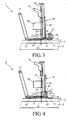
- the carrier 15 can be moved between a first position, in which the washer lying on the carrier is situated under the screwing device, see figure 3, and a second position, in which the washer lying on the carrier is situated under the means of placing, see figure 4.
- the means of placing 35 is a means of gripping 39, for gripping a washer, and an additional means of moving 41, in order to move the means of gripping.
- This additional means of moving 41 is also a cylinder with a movable piston in it and the means of gripping 39 in this embodiment is an electromagnet, which is attached to the piston's free end.
- the screw driving machine 1 has a screw feeding device 43.
- This has a generally known double ratchet mechanism (not visible in the figures) in order to move two discs, provided with teeth, gradually one tooth at a time. These discs take a strip along with them on which the screws are fastened.
- the screw feeding device 43 furthermore, has a screw guide 45, which guides the screws to a position under a screw head of the screwing device 31. When the discs are revolved the screws are released from the strip one by one in the known way and fall into the screw guide 45.
- the screw driving machine can be equipped with sensors (not shown in the figures) in order to be able to detect the tops 7 of the roofing sheets 5.
Abstract
Description
- The invention relates to a screw driving machine for screwing down roofing material on a roof of a building, comprising a screwing device, a washer holder for washers, a moveable carrier for a washer that is to be screwed down, a means of placing for taking a washer from the washer holder and placing it on the carrier, a screw feeding device, and a means of moving for moving the carrier between a first position under the screwing device and a second position under the means of placing.
- The washers are provided with a hole and are placed under the screw heads in order to distribute the force and to prevent the screws from damaging the roofing material. Such screw driving machines are usually provided with wheels with which they can be moved over the building's roof.
- Such a screw driving machine is known from the American patent US 6.064.189. With the known screw driving machine the washers are stacked and a washer is slid out each time from under the stack by a movable carrier. The carrier brings the washer over an opening in the bottom of the screw driving machine, after which the washer falls through the opening onto the roofing material. Then a screw is inserted in a hole situated in the washer, after which the roofing material is screwed down by means of a screwing device. The washers should be flat, because otherwise they will be held back by the washers lying above and it will not be possible to slide them from the stack.
- An objective of the invention is to provide a screw driving machine of the type described in the preamble in which washers of all shapes can be used. To this end, the screw driving machine according to the invention is characterized in that the means of placing comprises a means of gripping for gripping a washer, as well as an additional means of moving for moving the means of gripping. Because the washers are not slid from a stack, but are gripped one by one from the stack by the means of gripping, it is possible for them to be any shape desired. The washers can, for example, be corrugated.
- An embodiment of the screw driving machine according to the invention is characterized in that the washer holder is attached to the carrier. Because of this, the washer holder can be moved between a position under the means of gripping and a position at a distance from it, as a result of which the means of gripping only has to move in a vertical direction. Preferably, the means of moving can move mainly in a horizontal direction and the additional means of moving can move mainly in a vertical direction.
- Furthermore, the screw driving machine comprises a frame, which is provided with a mainly horizontal first guide, along which the carrier can be moved, and a mainly vertical second guide, along which the screwing device can be moved.
- A further embodiment of the screw driving machine according to the invention is characterized in that the means of gripping comprises a magnet, preferably, an electromagnet. By means of a magnet a washer can be gripped in a simple way. If the magnet is executed as an electromagnet, the washer can also simply be released again. Instead of or in combination with the magnet, the means of gripping may also comprise suction cups, as a result of which washers made of a material not attracted by a magnet can also be used. The disadvantage with this, however, is that the screw driving machine in that case must have a means of producing a vacuum.
- Preferably, the additional means of moving is also a cylinder with a piston which can move in it. In this embodiment, the means of gripping is preferably attached to the piston's free end.
- The invention will be elucidated more fully below on the basis of drawings in which an embodiment of the screw driving machine according to the invention is shown. In these drawings:
- Figure 1 shows a front view of an embodiment ofthe screw driving machine according to the invention;
- Figure 2 shows a view from above of the screw driving machine shown in figure 1;
- Figure 3 shows a side view of the screw driving machine shown in figure 1; and
- Figure 4 shows a side view of the screw driving machine shown in figure 1 during a different stage of the screwing process.
-
- In figures 1, 2 and 3 an embodiment of the screw driving machine according to the invention is shown in a front view, a view from above and a side view respectively. The
screw driving machine 1 is designed for screwing downroofing material 3 on a building's roof. Theroofing material 3 is screwed down at thetops 7 of acorrugated roofing sheet 5, in which washers are placed under the screw heads. - The
screw driving machine 1 is provided withwheels 9 and is moved manually over theroofing material 3 while driving the screws. To this end, thescrew driving machine 1 is provided with ahandgrip 11. Thewheels 9 are attached to aframe 13 on which there is amovable carrier 15 for washers. Thiscarrier 15 can be moved along a horizontalfirst guide 17 situated on the frame, and is provided with astop 19 against which awasher 21 can be positioned (see figure 2). There is aslot 23 in the carrier 15 (see figure 2) through which ascrew 25 is inserted during the process. There is also awasher holder 27 on thecarrier 15. This washer holder is made up of four vertical strips between which astack 29 of washers is situated. - The
screw driving machine 1, furthermore, has ascrewing device 31 that can be moved along asecond guide 33, situated vertically on theframe 13. Moreover, there is a means of placing 3 5 attached to theframe 13, for taking a washer from thewasher holder 27 and placing it on thecarrier 15. In order to move thecarrier 15, thescrew driving machine 1 is provided with a means of moving 37 that is a cylinder with a movable piston in it. Thecarrier 15 can be moved between a first position, in which the washer lying on the carrier is situated under the screwing device, see figure 3, and a second position, in which the washer lying on the carrier is situated under the means of placing, see figure 4. - The means of placing 35 is a means of gripping 39, for gripping a washer, and an additional means of moving 41, in order to move the means of gripping. This additional means of moving 41 is also a cylinder with a movable piston in it and the means of gripping 39 in this embodiment is an electromagnet, which is attached to the piston's free end.
- Furthermore, the
screw driving machine 1 has ascrew feeding device 43. This has a generally known double ratchet mechanism (not visible in the figures) in order to move two discs, provided with teeth, gradually one tooth at a time. These discs take a strip along with them on which the screws are fastened. Thescrew feeding device 43, furthermore, has ascrew guide 45, which guides the screws to a position under a screw head of thescrewing device 31. When the discs are revolved the screws are released from the strip one by one in the known way and fall into thescrew guide 45. There is aclamping device 47 under in thescrew guide 45 that clamps the screw. - In figures 3 and 4 the screw driving machine is shown during different stages of the screwing process. In the first position of the
carrier 15 shown in figure 3, a washer is gripped by theelectromagnet 39. Thecarrier 15 is then moved to a second position shown in figure 4. In this position thewasher 21 is placed on thecarrier 15 against thestop 19. Thecarrier 15 is then moved again to the first position, see figure 3. Ascrew 25 is now inserted in awasher 21 by thescrewing device 31 and partially screwed into theroofing material 3. Here, theclamp 47 releases thescrew 25. At the same time the next washer is taken from thestack 29. Thecarrier 15 is then moved again to the second position, see figure 4. Here, thewasher 21 is stopped by thescrew 25 and thecarrier 15 slides out from under the washer. Thescrew 25 can now be screwed further into theroofing material 3, and the next washer is laid on thecarrier 15. - Moreover, the screw driving machine can be equipped with sensors (not shown in the figures) in order to be able to detect the
tops 7 of theroofing sheets 5. - Although in the above the invention is explained on the basis of the drawings, it should be noted that the invention is in no way limited to the embodiment shown in the drawings. The invention also extends to all embodiments deviating from the embodiment shown in the drawings within the context defined by the claims.
Claims (6)
- Screw driving machine for screwing down roofing material on a building's roof, comprising a screwing device, a washer holder for washers, a movable carrier for a washer that is to be screwed down, a means of placing for taking a washer from the washer holder and placing it on the carrier, a screw feeding device and a means of moving for moving the carrier between a first position under the screwing device and a second position under the means of placing, characterized in that the means of placing comprises a means of gripping for gripping a washer, as well as an additional means of moving for moving the means of gripping.
- Screw driving machine according to claim 1, characterized in that the washer holder is attached to the carrier.
- Screw driving machine according to claim 1 or 2, characterized in that the means of moving can be moved mainly in a horizontal direction and the additional means of moving can be moved mainly in a vertical direction.
- Screw driving machine according to claim 1, 2 or 3, characterized in that the screw driving machine comprises a frame provided with a mainly horizontal first guide, along which the carrier can be moved, and a mainly vertical second guide, along which the screwing device can be moved.
- Screw driving machine according to one of the preceding claims characterized in that the means of gripping comprises a magnet, preferably an electromagnet.
- Screw driving machine according to one of the preceding claims, characterized in that the additional means of moving is a cylinder with a movable piston in it, in which the means of gripping is attached to the piston's free end.
Applications Claiming Priority (2)
| Application Number | Priority Date | Filing Date | Title |
|---|---|---|---|
| NL1025142 | 2003-12-29 | ||
| NL1025142A NL1025142C2 (en) | 2003-12-29 | 2003-12-29 | Screw device for screwing roof coverings. |
Publications (2)
| Publication Number | Publication Date |
|---|---|
| EP1550778A2 true EP1550778A2 (en) | 2005-07-06 |
| EP1550778A3 EP1550778A3 (en) | 2008-01-09 |
Family
ID=34568034
Family Applications (1)
| Application Number | Title | Priority Date | Filing Date |
|---|---|---|---|
| EP04078495A Withdrawn EP1550778A3 (en) | 2003-12-29 | 2004-12-23 | Screw apparatus for screwing a roofing |
Country Status (2)
| Country | Link |
|---|---|
| EP (1) | EP1550778A3 (en) |
| NL (1) | NL1025142C2 (en) |
Cited By (4)
| Publication number | Priority date | Publication date | Assignee | Title |
|---|---|---|---|---|
| NL1030013C2 (en) * | 2005-09-22 | 2007-03-23 | Marcus Franciscus The Engelaar | Device and method for placement of screws and pressure distribution members. |
| CN102092026A (en) * | 2010-12-03 | 2011-06-15 | 苏州市海新机电工业设备有限公司 | Screw trimming device |
| CN113442087A (en) * | 2021-05-20 | 2021-09-28 | 常州工学院 | Blow little draw ratio screw of nail formula and tighten up axle |
| US20210354936A1 (en) * | 2020-05-12 | 2021-11-18 | Omg, Inc. | Plate advancement mechanism for roofing tool |
Citations (1)
| Publication number | Priority date | Publication date | Assignee | Title |
|---|---|---|---|---|
| US6064189A (en) | 1998-03-04 | 2000-05-16 | Construction Fasteners, Inc. | Roof rib finder and fastening device using an inductive switch |
Family Cites Families (4)
| Publication number | Priority date | Publication date | Assignee | Title |
|---|---|---|---|---|
| US5058464A (en) * | 1989-09-28 | 1991-10-22 | Mcgovern Hubert T | Roof fastener installation machine |
| DE4413039C1 (en) * | 1994-04-15 | 1995-06-22 | Ivt H Blank | Setting device for holder plates for fixing strips on flat roofs |
| US5673816A (en) * | 1995-04-04 | 1997-10-07 | Illinois Tool Works Inc. | Roofing washer magazine for barbed roofing washers |
| US5960678A (en) * | 1997-04-29 | 1999-10-05 | Kennedy; Harley K. | Automatic stress plate feeder |
-
2003
- 2003-12-29 NL NL1025142A patent/NL1025142C2/en not_active IP Right Cessation
-
2004
- 2004-12-23 EP EP04078495A patent/EP1550778A3/en not_active Withdrawn
Patent Citations (1)
| Publication number | Priority date | Publication date | Assignee | Title |
|---|---|---|---|---|
| US6064189A (en) | 1998-03-04 | 2000-05-16 | Construction Fasteners, Inc. | Roof rib finder and fastening device using an inductive switch |
Cited By (7)
| Publication number | Priority date | Publication date | Assignee | Title |
|---|---|---|---|---|
| NL1030013C2 (en) * | 2005-09-22 | 2007-03-23 | Marcus Franciscus The Engelaar | Device and method for placement of screws and pressure distribution members. |
| WO2007035090A1 (en) * | 2005-09-22 | 2007-03-29 | Engelaar Marcus Franciscus The | Device and method for placing screws and pressure distribution members |
| CN102092026A (en) * | 2010-12-03 | 2011-06-15 | 苏州市海新机电工业设备有限公司 | Screw trimming device |
| CN102092026B (en) * | 2010-12-03 | 2013-04-03 | 苏州市海新机电工业设备有限公司 | Screw trimming device |
| US20210354936A1 (en) * | 2020-05-12 | 2021-11-18 | Omg, Inc. | Plate advancement mechanism for roofing tool |
| US11530099B2 (en) * | 2020-05-12 | 2022-12-20 | Omg, Inc. | Plate advancement mechanism for roofing tool |
| CN113442087A (en) * | 2021-05-20 | 2021-09-28 | 常州工学院 | Blow little draw ratio screw of nail formula and tighten up axle |
Also Published As
| Publication number | Publication date |
|---|---|
| EP1550778A3 (en) | 2008-01-09 |
| NL1025142C2 (en) | 2005-07-04 |
Similar Documents
| Publication | Publication Date | Title |
|---|---|---|
| CN106956163A (en) | A kind of fully automatic feeding equipment | |
| US6089434A (en) | Automatic frame maker | |
| EP1825941A2 (en) | Bar gripper for bar feeder | |
| CN206702737U (en) | A kind of fully automatic feeding equipment | |
| CN106271650A (en) | A kind of for vehicle dormer window guide rail automatic press former | |
| EP1550778A2 (en) | Screw apparatus for screwing a roofing | |
| CN105800347B (en) | A kind of sheet material drawing mechanism | |
| CN106572603B (en) | Automatic placement machine | |
| CN109399192B (en) | Automatic loading and unloading device for prime element polarization | |
| JP4486185B2 (en) | Plate material clamping device in plate material unloading device | |
| DE102015118601A1 (en) | Device and method for congruent laying of in a press to be pressed together workpiece layers | |
| CN209974930U (en) | Automatic board loading and unloading equipment for traditional electroplating production line of circuit board | |
| CN208977703U (en) | It is a kind of for arranging the clamping displaceable member of conjunction machine automatically | |
| JPH05123786A (en) | Device for carrying in plate in plate bending machine | |
| JP2733734B2 (en) | Method and apparatus for feeding two thin sheets simultaneously | |
| CN212686774U (en) | Carton material taking manipulator | |
| CN218822270U (en) | Multi-station bearing detection device | |
| CN116674834B (en) | Automatic attaching equipment for reflection strip | |
| CN218946827U (en) | Cutter blanking mechanism | |
| CN217534610U (en) | Separating mechanism and conveying device | |
| CN211305436U (en) | Rubber plug pulling device | |
| CN208979202U (en) | It is a kind of for arranging the embedded component of conjunction machine automatically | |
| CN211812199U (en) | Book bookmark mounting device | |
| CN111591730A (en) | Carton material taking manipulator | |
| JP2667707B2 (en) | Lead frame separation device |
Legal Events
| Date | Code | Title | Description |
|---|---|---|---|
| PUAI | Public reference made under article 153(3) epc to a published international application that has entered the european phase |
Free format text: ORIGINAL CODE: 0009012 |
|
| AK | Designated contracting states |
Kind code of ref document: A2 Designated state(s): AT BE BG CH CY CZ DE DK EE ES FI FR GB GR HU IE IS IT LI LT LU MC NL PL PT RO SE SI SK TR |
|
| AX | Request for extension of the european patent |
Extension state: AL BA HR LV MK YU |
|
| PUAL | Search report despatched |
Free format text: ORIGINAL CODE: 0009013 |
|
| AK | Designated contracting states |
Kind code of ref document: A3 Designated state(s): AT BE BG CH CY CZ DE DK EE ES FI FR GB GR HU IE IS IT LI LT LU MC NL PL PT RO SE SI SK TR |
|
| AX | Request for extension of the european patent |
Extension state: AL BA HR LV MK YU |
|
| AKX | Designation fees paid | ||
| REG | Reference to a national code |
Ref country code: DE Ref legal event code: 8566 |
|
| 17P | Request for examination filed |
Effective date: 20081030 |
|
| RBV | Designated contracting states (corrected) |
Designated state(s): AT BE BG CH CY CZ DE DK EE ES FI FR GB GR HU IE IS IT LI LT LU MC NL PL PT RO SE SI SK TR |
|
| GRAP | Despatch of communication of intention to grant a patent |
Free format text: ORIGINAL CODE: EPIDOSNIGR1 |
|
| STAA | Information on the status of an ep patent application or granted ep patent |
Free format text: STATUS: THE APPLICATION IS DEEMED TO BE WITHDRAWN |
|
| 18D | Application deemed to be withdrawn |
Effective date: 20091204 |