EP1552795A1 - Transponder with overlapping coil antennas on a common core - Google Patents
Transponder with overlapping coil antennas on a common core Download PDFInfo
- Publication number
- EP1552795A1 EP1552795A1 EP05250039A EP05250039A EP1552795A1 EP 1552795 A1 EP1552795 A1 EP 1552795A1 EP 05250039 A EP05250039 A EP 05250039A EP 05250039 A EP05250039 A EP 05250039A EP 1552795 A1 EP1552795 A1 EP 1552795A1
- Authority
- EP
- European Patent Office
- Prior art keywords
- power
- coil
- signal
- coils
- power coil
- Prior art date
- Legal status (The legal status is an assumption and is not a legal conclusion. Google has not performed a legal analysis and makes no representation as to the accuracy of the status listed.)
- Granted
Links
- 238000004891 communication Methods 0.000 claims abstract description 63
- 238000004804 winding Methods 0.000 claims description 21
- 238000000034 method Methods 0.000 claims description 20
- 230000005672 electromagnetic field Effects 0.000 claims description 12
- 230000008878 coupling Effects 0.000 claims description 11
- 238000010168 coupling process Methods 0.000 claims description 11
- 238000005859 coupling reaction Methods 0.000 claims description 11
- 238000012545 processing Methods 0.000 claims description 10
- 239000000463 material Substances 0.000 description 4
- 230000003071 parasitic effect Effects 0.000 description 4
- 239000000523 sample Substances 0.000 description 4
- 210000000481 breast Anatomy 0.000 description 3
- 230000008569 process Effects 0.000 description 3
- RYGMFSIKBFXOCR-UHFFFAOYSA-N Copper Chemical compound [Cu] RYGMFSIKBFXOCR-UHFFFAOYSA-N 0.000 description 2
- 230000005540 biological transmission Effects 0.000 description 2
- 230000006698 induction Effects 0.000 description 2
- 230000004044 response Effects 0.000 description 2
- 238000001356 surgical procedure Methods 0.000 description 2
- 229910000859 α-Fe Inorganic materials 0.000 description 2
- 230000000712 assembly Effects 0.000 description 1
- 238000000429 assembly Methods 0.000 description 1
- 238000001574 biopsy Methods 0.000 description 1
- 238000002405 diagnostic procedure Methods 0.000 description 1
- 230000000694 effects Effects 0.000 description 1
- 238000002513 implantation Methods 0.000 description 1
- 230000003902 lesion Effects 0.000 description 1
- 238000002324 minimally invasive surgery Methods 0.000 description 1
- 238000012986 modification Methods 0.000 description 1
- 230000004048 modification Effects 0.000 description 1
- 230000035699 permeability Effects 0.000 description 1
- 230000001105 regulatory effect Effects 0.000 description 1
- 238000000926 separation method Methods 0.000 description 1
- 239000000126 substance Substances 0.000 description 1
- 239000000758 substrate Substances 0.000 description 1
- 238000012546 transfer Methods 0.000 description 1
- 238000011277 treatment modality Methods 0.000 description 1
Images

Classifications
-
- H—ELECTRICITY
- H04—ELECTRIC COMMUNICATION TECHNIQUE
- H04B—TRANSMISSION
- H04B1/00—Details of transmission systems, not covered by a single one of groups H04B3/00 - H04B13/00; Details of transmission systems not characterised by the medium used for transmission
- H04B1/59—Responders; Transponders
-
- H—ELECTRICITY
- H01—ELECTRIC ELEMENTS
- H01Q—ANTENNAS, i.e. RADIO AERIALS
- H01Q5/00—Arrangements for simultaneous operation of antennas on two or more different wavebands, e.g. dual-band or multi-band arrangements
- H01Q5/40—Imbricated or interleaved structures; Combined or electromagnetically coupled arrangements, e.g. comprising two or more non-connected fed radiating elements
- H01Q5/42—Imbricated or interleaved structures; Combined or electromagnetically coupled arrangements, e.g. comprising two or more non-connected fed radiating elements using two or more imbricated arrays
-
- A—HUMAN NECESSITIES
- A61—MEDICAL OR VETERINARY SCIENCE; HYGIENE
- A61B—DIAGNOSIS; SURGERY; IDENTIFICATION
- A61B90/00—Instruments, implements or accessories specially adapted for surgery or diagnosis and not covered by any of the groups A61B1/00 - A61B50/00, e.g. for luxation treatment or for protecting wound edges
- A61B90/39—Markers, e.g. radio-opaque or breast lesions markers
-
- H—ELECTRICITY
- H01—ELECTRIC ELEMENTS
- H01Q—ANTENNAS, i.e. RADIO AERIALS
- H01Q25/00—Antennas or antenna systems providing at least two radiating patterns
-
- H—ELECTRICITY
- H01—ELECTRIC ELEMENTS
- H01Q—ANTENNAS, i.e. RADIO AERIALS
- H01Q5/00—Arrangements for simultaneous operation of antennas on two or more different wavebands, e.g. dual-band or multi-band arrangements
- H01Q5/40—Imbricated or interleaved structures; Combined or electromagnetically coupled arrangements, e.g. comprising two or more non-connected fed radiating elements
-
- H—ELECTRICITY
- H01—ELECTRIC ELEMENTS
- H01Q—ANTENNAS, i.e. RADIO AERIALS
- H01Q7/00—Loop antennas with a substantially uniform current distribution around the loop and having a directional radiation pattern in a plane perpendicular to the plane of the loop
-
- H—ELECTRICITY
- H01—ELECTRIC ELEMENTS
- H01Q—ANTENNAS, i.e. RADIO AERIALS
- H01Q7/00—Loop antennas with a substantially uniform current distribution around the loop and having a directional radiation pattern in a plane perpendicular to the plane of the loop
- H01Q7/06—Loop antennas with a substantially uniform current distribution around the loop and having a directional radiation pattern in a plane perpendicular to the plane of the loop with core of ferromagnetic material
-
- A—HUMAN NECESSITIES
- A61—MEDICAL OR VETERINARY SCIENCE; HYGIENE
- A61B—DIAGNOSIS; SURGERY; IDENTIFICATION
- A61B90/00—Instruments, implements or accessories specially adapted for surgery or diagnosis and not covered by any of the groups A61B1/00 - A61B50/00, e.g. for luxation treatment or for protecting wound edges
- A61B90/39—Markers, e.g. radio-opaque or breast lesions markers
- A61B2090/397—Markers, e.g. radio-opaque or breast lesions markers electromagnetic other than visible, e.g. microwave
-
- A—HUMAN NECESSITIES
- A61—MEDICAL OR VETERINARY SCIENCE; HYGIENE
- A61B—DIAGNOSIS; SURGERY; IDENTIFICATION
- A61B5/00—Measuring for diagnostic purposes; Identification of persons
- A61B5/07—Endoradiosondes
- A61B5/076—Permanent implantations
Definitions
- the present invention relates generally to wireless transponder devices, and specifically to miniaturized antenna assemblies for use in such devices.
- Passive wireless transponders are known in the art. "Passive” in this context means that the transponder includes no internal energy source, such as a battery. Typically, such transponders receive the energy they need to operate by induction from an external radiofrequency (RF) electromagnetic field.
- the transponder generally comprises both a power antenna, for receiving energy from the field, and a communication antenna, for transmitting and/or receiving communication signals to and/or from an external base station.
- RF radiofrequency
- the transponder may be used, inter alia , to transmit and receive signals used in determining the location of an object within the body of a patient. Transponders of this sort are described, for example, in EP-A-1 321 097.
- U.S. Patent 6,239,724 describes a telemetry system for providing spatial positioning information from within a patient's body.
- the system includes an implantable telemetry unit having (a) a first transducer, for converting a power signal received from outside the body into electrical power for powering the telemetry unit; (b) a second transducer, for receiving a positioning field signal that is received from outside the body; and (c) a third transducer, for transmitting a locating signal to a site outside the body, in response to the positioning field signal.
- PCT patent publication WO 00/38571 A1 and U.S. Patent 6,261,247, to Ishikawa et al. describe an anatomical position sensing system using one or more substantially spherical transponders for measuring relative positions and distances.
- the transponders are capable of receiving and transmitting RF signals, thus communicating between themselves and with a separate CPU.
- the CPU controls a broadband antenna to transmit a low-frequency RF power signal to energize the transponders. Once energized, the transponders transmit range signals in all directions at other frequencies. These signals are used in determining the positions of the transponders.
- the transponder is fabricated on a spherical substrate, and includes nine coils in three sets of three coils. Each set is orthogonal to the others and comprises three coils: one transmit coil, one receive coil, and one power coupling coil. The coil sets are grouped in this fashion to ensure that at least one coil set is oriented to provide potentially optimum power coupling and signal communication therewith.
- Each of the power coupling coils is connected to a power circuit, which rectifies the varying magnetic energy coupled into the coil.
- the power circuits are connected in series to provide power to the other transponder circuits.
- an antenna assembly comprises overlapping power coils and communication coils wound on a common core.
- the power coils comprise at least two coils, and preferably three coils, which are wound over a relatively large area of the core in different, respective directions.
- three power coils are wound over substantially the entire core area in orthogonal directions. This arrangement maximizes the effective area (and thus the inductance) of the coils and ensures that at least one of the power coils will receive energy from an external transmitter, regardless of the orientations of the transmitter and the transponder.
- the power coils are coupled to power circuits, which rectify the energy received by the power coils and thus provide operating power to a communication circuit, which transmits or receives signals through the communication coils.
- the communication coils substantially overlap the power coils. Winding the communication and power coils on the same core in this manner, as opposed to using separate cores or a non-overlapping coil arrangement, reduces the size of the antenna assembly that is required in order to achieve a given antenna gain, and thus reduces the size of the transponder as a whole relative to passive transponders known in the art.
- the communication coils are wound over only a portion of the area of the core in each winding direction, in order to reduce parasitic effects that would otherwise spoil the resonance quality factor (Q) of the power circuit.
- the communication coil that is wound around the core in a given direction is preferably not wound directly over the power coil that is wound in the same direction. Rather, the order of winding the coils on the core is such that another coil, typically a power coil wound in a different direction, intervenes between each communication coil and power coil that are wound in the same direction.
- the wireless transponder is used in an electromagnetic position sensing system, typically in order to determine the location of an object to which the transponder is fixed inside the body of a patient.
- a wireless device including:
- the first power coil has a power coil width
- the first signal coil has a signal coil width that is substantially less than the power coil width.
- the core includes a polyhedron having a face width
- the first power coil has a first power coil width that is equal to at least about 80% of the face width, while the first signal coil width is less than about 50% of the first power coil width. In one embodiment, the first signal coil width is less than about 20% of the first power coil width.
- the one or more power coils include at least second and third power coils having respective second and third power coil axes, wherein the first, second and third power coil axes are mutually substantially orthogonal.
- the one or more signal coils include at least second and third signal coils, having respective second and third signal coil axes that are respectively substantially parallel to the second and third power coil axes.
- the power coils and signal coils are wound so that between each pair of the first power coil and the first signal coil, the second power coil and the second signal coil, and the third power coil and the third signal coil, another of the coils, typically another of the power coils, is wound.
- the one or more power coils include at least a second power coil, having a second power coil axis that is substantially non-parallel to the first power coil axis, wherein the second power coil is wound between the first power coil and the first signal coil.
- the communication circuitry is adapted to receive the second radio signals via the signal coils, and to transmit third radio signals that are indicative of a location of the device, responsively to the second radio signals received by the communication circuitry.
- the communication circuitry may be coupled to transmit the third radio signals via the power coils.
- apparatus for tracking an object including:
- the transponder is adapted to be inserted, together with the object, into a body of a subject, while the power transmitter and the one or more field generators are placed outside the body.
- the communication circuitry may be coupled to transmit the output signals via the power coils.
- a method for wireless sensing including:
- a method for tracking an object including:
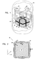
- Fig. 1 is a schematic, cutaway illustration of a wireless transponder 20, in accordance with an embodiment of the present invention.
- the transponder comprises an antenna assembly, comprising power coils 24, 26 and 28 and communication coils 30, 32 and 34, which are wound on a core 36.
- the core comprises a material with high magnetic permeability, such as a ferrite or a Wiegand effect material, as described, for example, in EP-A-1 266 613.
- core 36 may comprise any other suitable material known in the art.
- Power coils 24, 26 and 28 typically comprise wires of a relatively large gauge, which are wound over substantially the entire surface of core 36 in mutually-orthogonal directions.
- Communication coils comprise thinner-gauge wires, and are wound so as to overlap the power coils over only a portion of the surface of the core, typically near the center lines of the faces of the core as shown in the figure.
- Power coils 24, 26 and 28 are coupled to a power circuit 38.
- the power circuit comprises capacitive elements, coupled to each of the power coils, so as to define resonant circuits.
- the resonant circuits are preferably designed to have a sharp resonance (i.e., high Q, typically in the range of about 150) at the transmission frequency of the transmitter, which is typically a permitted ISI frequency, such as 13.56 MHz.
- each resonant circuit is coupled to a rectifier, and the rectified outputs are connected in series to give a DC output.
- the DC output may be regulated in order to maintain a steady output voltage level.
- a suitable power circuit meeting these general requirements is described, for example, by Ishikawa et al. in the above-mentioned U.S. patent and PCT publication.
- the DC output from power circuit 38 provides operating power to a communication circuit 40.
- the communication circuit may either transmit or receive signals, or it may both transmit and receive signals, to and from an external receiver and/or transmitter (not shown in this figure).
- circuit 40 may comprise a transmitter, which is coupled to transmit signals via communication coils 30, 32 and 34.
- An external receiver may in this case receive and process the signals in order to determine position coordinates of transponder 20. An embodiment of this sort is shown in Fig. 3.
- circuit 40 may comprise a receiver, which receives signals via coils 30, 32 and 34 from one or more external transmitters.
- these signals may comprise position reference signals, which are transmitted by a set of magnetic field generators in fixed locations at different, respective frequencies, typically in the range of one to several kilohertz. These fields cause currents to flow in coils 30, 32 and 34 by induction. The amplitudes and phases of the currents depend on the spatial position and orientation of coils 30, 32 and 34 relative to the field generators.
- Communication circuit 40 receives and processes these currents in order to generate signals for transmission to an externally-located signal processing unit (as shown in Fig. 3), which processes the signals to determine position coordinates of transponder 20.
- the communication circuit may convert the currents from coils 30, 32 and 34 into high-frequency signals.
- Circuit 40 may transmit the signals to the signal processing unit either via communication coils 30, 32 and 34, or via power coils 24, 26 and 28, or via a further set of transmit coils (not shown), which may be wound on core 36, as well.
- Exemplary position sensing systems operating on principles similar to these are further described in the above-mentioned EP-A-1 321 097 and U.S. Patent 6,239,724.
- transponder may comprise another type of sensor (not shown), such as a temperature sensor, a pressure sensor or a chemical sensor, for example.
- communication circuit 40 transmits signals via coils 30, 32 and 34 indicating the sensor readings to an external receiver.
- Fig. 2 is a schematic, sectional illustration of antenna assembly 22, in accordance with an embodiment of the present invention.
- Core 36 is typically polyhedral in shape.
- core 36 comprises a cube of ferrite material, with faces that are about 3 mm wide.
- the core may be round, oval, or of any other suitable shape known in the art.
- Each of power coils 24, 26 and 28 comprises approximately twenty turns of copper wire, whose diameter is between about 70 and 120 ⁇ m. Comparatively thick wire is used for the power coils because they must carry relatively high power, typically on the order of 5 mW.
- the power coils are wound over substantially the entire width of the core, typically covering at least 80% of each of the faces of the core, and preferably close to 100%.
- the communication coils are wound only in the center of each face, typically in a strip about 0.5 mm wide.
- the width of each of the communication coils is no more than about 50% of the width of the power coil that it overlaps with the same coil axis, and most preferably the communication coil width is no more than about 20% of the width of the power coil.
- the term "width,” when used in reference to a coil, means the extent of the coil measured along the direction of its axis.
- Winding the power coils over substantially the entire core is desirable in order to increase their inductance, and hence to increase the power generated by power circuit 38 relative to the size of assembly 22.
- Winding the communication coils in a narrower strip reduces their parasitic effect on the power coils. This parasitic effect tends to reduce the Q factor of the resonant power circuits.
- other winding configurations of the communication coils may be used.
- the power and communication coils are wound in the following order, beginning from core 36 and moving outward: power coil 28, communication coil 30, power coil 26, communication coil 34, power coil 24 and communication coil 32.
- the order is Z-power, X-communication, Y-power, Z-communication, X-power, Y-communication.
- Each of the communication coils is separated from the power coil with the same axis by at least one other coil, and preferably at least one other power coil. It has been found that this separation is useful in reducing the mutual parasitic effects of the overlapping power and communication coils.
- other winding orders are possible, for example: Z-power, Y-power, X-power, Z-communication, Y-communication, X-communication.
- FIG. 3 is schematic, pictorial illustration of a system 50 for guiding a surgical probe 52 to the location of wireless transponder 20 in a breast 54 of a subject, in accordance with an embodiment of the present invention.
- transponder 20 is suitably encapsulated for implantation within the body and was previously implanted in breast 54 at the site of a suspected lesion, typically under radiographic observation.
- Probe 52 is then used to extract a tissue sample from the site for the purpose of biopsy. Further details of this and other applications of wireless "tags," such as transponder 20, are described in EP-A-1 374 792.
- a power transmitter typically in the form of a power coil 56, generates a high-frequency RF field, which causes a current to flow in at least one of power coils 24, 26 and 28. This current is rectified by power circuit 38 in order to power communication circuit 40.
- field generator coils 58 produce electromagnetic fields, typically in the 1-8 kHz range, which cause alternating currents to flow in communication coils 30, 32 and 34. These currents have frequency components at the same frequencies as the driving currents flowing through the generator coils. The current components are proportional to the strengths of the components of the respective magnetic fields produced by the generator coils in a direction parallel to the sensor coil axis. Thus, the amplitudes of the currents indicate the position and orientation of coils 30, 32 and 34 (and hence of transponder 20) relative to fixed generator coils 58.
- Circuit 40 encodes the current amplitudes from coils 30, 32 and 34 into a high-frequency signal, which is transmitted via either these coils or via power coils 24, 26 and 28.
- transponder 20 may comprise additional antennas for transmitting signals.
- the encoded signal is received by coil 56 or by another receiving antenna, and is conveyed to a processing unit 60.
- the processing unit comprises a general-purpose computer, with suitable input circuits and software for processing the position signals received over the air from transponder 20.
- the processing unit computes position and, optionally, orientation coordinates of the transponder, and then shows the tag coordinates on a display 62.
- Surgical tool 52 also comprises a position sensor 64, typically comprising one or more coils similar in form and function to coils 30, 32 and 34 in transponder 20.
- the fields produced by field generator coils 68 also cause currents to flow in sensor 64, in response to the position and orientation of tool 52 relative to coils 68.
- the current signals thus produced are also conveyed to processing unit 60, either over the air, as in the case of transponder 20, or via wire.
- processing unit 60 Based on the signals from transponder 20 and from sensor 64, processing unit 60 computes the position and orientation of tool 52 relative to the location of the transponder in breast 54.
- a pointer and/or cursor is shown on display 62 to indicate to the surgeon whether the tool is aimed properly towards its target.
- Various methods of coordinate display may be used for this purpose, as described, for example, in the above-mentioned EP-A-1 374 792 and U.S. Patent 6,332,098.
- Fig. 3 is directed to a certain specific surgical procedure, other areas of application of transponder 20 and of the techniques taught by the present invention will be apparent to those skilled in the art.
- the principles of the present invention may similarly be applied to other types of surgery, including particularly minimally-invasive surgery, endoscopic and non-invasive treatment modalities, and diagnostic procedures, as well as non-medical applications.
Abstract
Description
- The present invention relates generally to wireless transponder devices, and specifically to miniaturized antenna assemblies for use in such devices.
- Passive wireless transponders are known in the art. "Passive" in this context means that the transponder includes no internal energy source, such as a battery. Typically, such transponders receive the energy they need to operate by induction from an external radiofrequency (RF) electromagnetic field. For this purpose, the transponder generally comprises both a power antenna, for receiving energy from the field, and a communication antenna, for transmitting and/or receiving communication signals to and/or from an external base station. Such transponders may be used, inter alia, to transmit and receive signals used in determining the location of an object within the body of a patient. Transponders of this sort are described, for example, in EP-A-1 321 097.
- As another example, U.S. Patent 6,239,724, to Doron et al., describes a telemetry system for providing spatial positioning information from within a patient's body. The system includes an implantable telemetry unit having (a) a first transducer, for converting a power signal received from outside the body into electrical power for powering the telemetry unit; (b) a second transducer, for receiving a positioning field signal that is received from outside the body; and (c) a third transducer, for transmitting a locating signal to a site outside the body, in response to the positioning field signal.
- PCT patent publication WO 00/38571 A1 and U.S. Patent 6,261,247, to Ishikawa et al. describe an anatomical position sensing system using one or more substantially spherical transponders for measuring relative positions and distances. The transponders are capable of receiving and transmitting RF signals, thus communicating between themselves and with a separate CPU. The CPU controls a broadband antenna to transmit a low-frequency RF power signal to energize the transponders. Once energized, the transponders transmit range signals in all directions at other frequencies. These signals are used in determining the positions of the transponders.
- In one embodiment described by Ishikawa et al., the transponder is fabricated on a spherical substrate, and includes nine coils in three sets of three coils. Each set is orthogonal to the others and comprises three coils: one transmit coil, one receive coil, and one power coupling coil. The coil sets are grouped in this fashion to ensure that at least one coil set is oriented to provide potentially optimum power coupling and signal communication therewith. Each of the power coupling coils is connected to a power circuit, which rectifies the varying magnetic energy coupled into the coil. The power circuits are connected in series to provide power to the other transponder circuits.
- Embodiments of the present invention provide improved antenna designs for wireless transponders. In these embodiments, an antenna assembly comprises overlapping power coils and communication coils wound on a common core. The power coils comprise at least two coils, and preferably three coils, which are wound over a relatively large area of the core in different, respective directions. Preferably, three power coils are wound over substantially the entire core area in orthogonal directions. This arrangement maximizes the effective area (and thus the inductance) of the coils and ensures that at least one of the power coils will receive energy from an external transmitter, regardless of the orientations of the transmitter and the transponder. The power coils are coupled to power circuits, which rectify the energy received by the power coils and thus provide operating power to a communication circuit, which transmits or receives signals through the communication coils.
- Since the power coils are typically wound over most or all of the area of the core in two or three different directions, the communication coils substantially overlap the power coils. Winding the communication and power coils on the same core in this manner, as opposed to using separate cores or a non-overlapping coil arrangement, reduces the size of the antenna assembly that is required in order to achieve a given antenna gain, and thus reduces the size of the transponder as a whole relative to passive transponders known in the art. Typically, the communication coils are wound over only a portion of the area of the core in each winding direction, in order to reduce parasitic effects that would otherwise spoil the resonance quality factor (Q) of the power circuit. For similar reasons, the communication coil that is wound around the core in a given direction is preferably not wound directly over the power coil that is wound in the same direction. Rather, the order of winding the coils on the core is such that another coil, typically a power coil wound in a different direction, intervenes between each communication coil and power coil that are wound in the same direction.
- In some embodiments of the present invention, the wireless transponder is used in an electromagnetic position sensing system, typically in order to determine the location of an object to which the transponder is fixed inside the body of a patient.
- There is therefore provided, in accordance with an embodiment of the present invention, a wireless device, including:
- an antenna assembly, including:
- a core;
- one or more power coils, wound around the core on respective power coil axes, including at least a first power coil having a first power coil axis; and
- one or more signal coils, wound around the core on respective signal coil axes, including at least a first signal coil wound so as to overlap the first power coil, the first signal coil having a first signal coil axis that is substantially parallel to the first power coil axis;
- power circuitry, coupled to the power coils so as to receive therefrom first radio signals in a first frequency band, and to rectify the first radio signals so as to generate a direct current; and
- communication circuitry, powered by the direct current, and coupled to perform at least one of transmitting and receiving second radio signals in a second frequency band via the signal coils.
-
- In some embodiments, the first power coil has a power coil width, and the first signal coil has a signal coil width that is substantially less than the power coil width. Typically, the core includes a polyhedron having a face width, and the first power coil has a first power coil width that is equal to at least about 80% of the face width, while the first signal coil width is less than about 50% of the first power coil width. In one embodiment, the first signal coil width is less than about 20% of the first power coil width.
- In disclosed embodiments, the one or more power coils include at least second and third power coils having respective second and third power coil axes, wherein the first, second and third power coil axes are mutually substantially orthogonal. Typically, the one or more signal coils include at least second and third signal coils, having respective second and third signal coil axes that are respectively substantially parallel to the second and third power coil axes. In one embodiment, the power coils and signal coils are wound so that between each pair of the first power coil and the first signal coil, the second power coil and the second signal coil, and the third power coil and the third signal coil, another of the coils, typically another of the power coils, is wound.
- Typically, the one or more power coils include at least a second power coil, having a second power coil axis that is substantially non-parallel to the first power coil axis, wherein the second power coil is wound between the first power coil and the first signal coil.
- In a disclosed embodiment, the communication circuitry is adapted to receive the second radio signals via the signal coils, and to transmit third radio signals that are indicative of a location of the device, responsively to the second radio signals received by the communication circuitry. The communication circuitry may be coupled to transmit the third radio signals via the power coils.
- There is also provided, in accordance with an embodiment of the present invention, apparatus for tracking an object, including:
- a power transmitter, adapted to radiate radio frequency (RF) energy toward the object in a first frequency band;
- one or more field generators, adapted to generate electromagnetic fields in a second frequency band in a vicinity of the object;
- a wireless transponder, adapted to be fixed to the object and including:
- an antenna assembly, including:
- a core;
- one or more power coils, wound around the core on respective power coil axes, including at least a first power coil having a first power coil axis; and
- one or more signal coils, wound around the core on respective signal coil axes, including at least a first signal coil wound so as to overlap the first power coil, the first signal coil having a first signal coil axis that is substantially parallel to the first power coil axis;
- power circuitry, coupled to the power coils so as to receive therefrom the RF energy in the first frequency band, and to rectify the RF energy so as to generate a direct current; and
- communication circuitry, powered by the direct current, and coupled to sense an alternating current flowing in the signal coils due to the electromagnetic fields in the second frequency band, and to transmit output signals indicative of the alternating current; and
- a signal receiver, adapted to receive the output signals and, responsively to the output signals, to determine coordinates of the object.
-
- Typically, the transponder is adapted to be inserted, together with the object, into a body of a subject, while the power transmitter and the one or more field generators are placed outside the body.
- The communication circuitry may be coupled to transmit the output signals via the power coils.
- There is additionally provided, in accordance with an embodiment of the present invention, a method for wireless sensing, including:
- winding one or more power coils around a core on respective power coil axes, including winding at least a first power coil on a first power coil axis;
- winding one or more signal coils around the core on respective signal coil axes, including winding at least a first signal coil so as to overlap the first power coil, the first signal coil having a first signal coil axis that is substantially parallel to the first power coil axis;
- coupling power circuitry to receive first radio signals in a first frequency band from the power coils, and to rectify the first radio signals so as to generate a direct current;
- coupling communication circuitry to perform at least one of transmitting and receiving second radio signals in a second frequency band via the signal coils; and
- applying the direct current from the power circuitry to power the communication circuitry.
-
- There is further provided, in accordance with an embodiment of the present invention, a method for tracking an object, including:
- fixing a wireless transponder to the object, the wireless transponder including:
- an antenna assembly, including:
- a core;
- one or more power coils, wound around the core on respective power coil axes, including at least a first power coil having a first power coil axis; and
- one or more signal coils, wound around the core on respective signal coil axes, including at least a first signal coil wound so as to overlap the first power coil, the first signal coil having a first signal coil axis that is substantially parallel to the first power coil axis;
- power circuitry, coupled to the power coils so as to receive therefrom the RF energy in a first frequency band, and to rectify the RF energy so as to generate a direct current; and
- communication circuitry, powered by the direct current, and coupled to sense an alternating current flowing in the signal coils due to the electromagnetic fields in a second frequency band, and to transmit output signals indicative of the alternating current;
- radiating radio frequency (RF) energy toward the object in the first frequency band so as to supply the RF energy via the power coils to the power circuitry;
- generating electromagnetic fields in a second frequency band in a vicinity of the object so as to cause the alternating current to flow in the signal coils; and
- receiving and processing the output signals transmitted by the transponder so as to determine coordinates of the object.
-
- The present invention will be more fully understood from the following detailed description of the embodiments thereof, taken together with the drawings in which:
- Fig. 1 is a schematic, cutaway illustration of a wireless transponder, in accordance with an embodiment of the present invention;
- Fig. 2 is a schematic, sectional illustration of an antenna assembly used in a wireless transponder, in accordance with an embodiment of the present invention; and
- Fig. 3 is a schematic, pictorial illustration of a system for guiding a surgical probe to the location of a wireless transponder in the body of a subject, in accordance with an embodiment of the present invention.
-
- Fig. 1 is a schematic, cutaway illustration of a
wireless transponder 20, in accordance with an embodiment of the present invention. The transponder comprises an antenna assembly, comprising power coils 24, 26 and 28 and communication coils 30, 32 and 34, which are wound on acore 36. Typically, the core comprises a material with high magnetic permeability, such as a ferrite or a Wiegand effect material, as described, for example, in EP-A-1 266 613. Alternatively,core 36 may comprise any other suitable material known in the art. Power coils 24, 26 and 28 typically comprise wires of a relatively large gauge, which are wound over substantially the entire surface ofcore 36 in mutually-orthogonal directions. Communication coils comprise thinner-gauge wires, and are wound so as to overlap the power coils over only a portion of the surface of the core, typically near the center lines of the faces of the core as shown in the figure. - Power coils 24, 26 and 28 are coupled to a
power circuit 38. Typically, the power circuit comprises capacitive elements, coupled to each of the power coils, so as to define resonant circuits. For efficient power transfer from an external RF transmitter (not shown in this figure) to the coils, the resonant circuits are preferably designed to have a sharp resonance (i.e., high Q, typically in the range of about 150) at the transmission frequency of the transmitter, which is typically a permitted ISI frequency, such as 13.56 MHz. Typically, each resonant circuit is coupled to a rectifier, and the rectified outputs are connected in series to give a DC output. The DC output may be regulated in order to maintain a steady output voltage level. A suitable power circuit meeting these general requirements is described, for example, by Ishikawa et al. in the above-mentioned U.S. patent and PCT publication. - The DC output from
power circuit 38 provides operating power to acommunication circuit 40. The communication circuit may either transmit or receive signals, or it may both transmit and receive signals, to and from an external receiver and/or transmitter (not shown in this figure). For example,circuit 40 may comprise a transmitter, which is coupled to transmit signals via communication coils 30, 32 and 34. An external receiver may in this case receive and process the signals in order to determine position coordinates oftransponder 20. An embodiment of this sort is shown in Fig. 3. - Additionally or alternatively,
circuit 40 may comprise a receiver, which receives signals viacoils coils coils Communication circuit 40 receives and processes these currents in order to generate signals for transmission to an externally-located signal processing unit (as shown in Fig. 3), which processes the signals to determine position coordinates oftransponder 20. For example, the communication circuit may convert the currents fromcoils Circuit 40 may transmit the signals to the signal processing unit either via communication coils 30, 32 and 34, or via power coils 24, 26 and 28, or via a further set of transmit coils (not shown), which may be wound oncore 36, as well. Exemplary position sensing systems operating on principles similar to these (but without the novel antenna assembly of the present invention) are further described in the above-mentioned EP-A-1 321 097 and U.S. Patent 6,239,724. - Further additionally or alternatively, transponder may comprise another type of sensor (not shown), such as a temperature sensor, a pressure sensor or a chemical sensor, for example. In this case,
communication circuit 40 transmits signals viacoils - Fig. 2 is a schematic, sectional illustration of
antenna assembly 22, in accordance with an embodiment of the present invention.Core 36 is typically polyhedral in shape. In this embodiment,core 36 comprises a cube of ferrite material, with faces that are about 3 mm wide. Alternatively, the core may be round, oval, or of any other suitable shape known in the art. Each of power coils 24, 26 and 28 comprises approximately twenty turns of copper wire, whose diameter is between about 70 and 120 µm. Comparatively thick wire is used for the power coils because they must carry relatively high power, typically on the order of 5 mW. Communication coils 30, 32 and 34, which carry substantially smaller currents, typically comprise 500 turns of copper wire, with diameter between about 10 and 16 µm. As shown in the figures, the power coils are wound over substantially the entire width of the core, typically covering at least 80% of each of the faces of the core, and preferably close to 100%. The communication coils, on the other hand, are wound only in the center of each face, typically in a strip about 0.5 mm wide. - Preferably, the width of each of the communication coils is no more than about 50% of the width of the power coil that it overlaps with the same coil axis, and most preferably the communication coil width is no more than about 20% of the width of the power coil. (In the context of the present patent application and in the claims, the term "width," when used in reference to a coil, means the extent of the coil measured along the direction of its axis.) Winding the power coils over substantially the entire core is desirable in order to increase their inductance, and hence to increase the power generated by
power circuit 38 relative to the size ofassembly 22. Winding the communication coils in a narrower strip reduces their parasitic effect on the power coils. This parasitic effect tends to reduce the Q factor of the resonant power circuits. Alternatively, other winding configurations of the communication coils may be used. - In the present embodiment, the power and communication coils are wound in the following order, beginning from
core 36 and moving outward:power coil 28,communication coil 30,power coil 26,communication coil 34,power coil 24 andcommunication coil 32. In other words, in terms of the coil axis directions shown in the figure, the order is Z-power, X-communication, Y-power, Z-communication, X-power, Y-communication. Each of the communication coils is separated from the power coil with the same axis by at least one other coil, and preferably at least one other power coil. It has been found that this separation is useful in reducing the mutual parasitic effects of the overlapping power and communication coils. Alternatively, other winding orders are possible, for example: Z-power, Y-power, X-power, Z-communication, Y-communication, X-communication. - Fig. 3 is schematic, pictorial illustration of a
system 50 for guiding asurgical probe 52 to the location ofwireless transponder 20 in abreast 54 of a subject, in accordance with an embodiment of the present invention. In the surgical application shown in this figure, it is assumed thattransponder 20 is suitably encapsulated for implantation within the body and was previously implanted inbreast 54 at the site of a suspected lesion, typically under radiographic observation.Probe 52 is then used to extract a tissue sample from the site for the purpose of biopsy. Further details of this and other applications of wireless "tags," such astransponder 20, are described in EP-A-1 374 792. - A power transmitter, typically in the form of a
power coil 56, generates a high-frequency RF field, which causes a current to flow in at least one of power coils 24, 26 and 28. This current is rectified bypower circuit 38 in order topower communication circuit 40. Meanwhile, field generator coils 58 produce electromagnetic fields, typically in the 1-8 kHz range, which cause alternating currents to flow in communication coils 30, 32 and 34. These currents have frequency components at the same frequencies as the driving currents flowing through the generator coils. The current components are proportional to the strengths of the components of the respective magnetic fields produced by the generator coils in a direction parallel to the sensor coil axis. Thus, the amplitudes of the currents indicate the position and orientation ofcoils -
Circuit 40 encodes the current amplitudes fromcoils transponder 20 may comprise additional antennas for transmitting signals. The encoded signal is received bycoil 56 or by another receiving antenna, and is conveyed to aprocessing unit 60. Typically, the processing unit comprises a general-purpose computer, with suitable input circuits and software for processing the position signals received over the air fromtransponder 20. The processing unit computes position and, optionally, orientation coordinates of the transponder, and then shows the tag coordinates on adisplay 62. -
Surgical tool 52 also comprises aposition sensor 64, typically comprising one or more coils similar in form and function tocoils transponder 20. The fields produced by field generator coils 68 also cause currents to flow insensor 64, in response to the position and orientation oftool 52 relative to coils 68. The current signals thus produced are also conveyed toprocessing unit 60, either over the air, as in the case oftransponder 20, or via wire. Based on the signals fromtransponder 20 and fromsensor 64, processingunit 60 computes the position and orientation oftool 52 relative to the location of the transponder inbreast 54. A pointer and/or cursor is shown ondisplay 62 to indicate to the surgeon whether the tool is aimed properly towards its target. Various methods of coordinate display may be used for this purpose, as described, for example, in the above-mentioned EP-A-1 374 792 and U.S. Patent 6,332,098. - Although the embodiment of Fig. 3 is directed to a certain specific surgical procedure, other areas of application of
transponder 20 and of the techniques taught by the present invention will be apparent to those skilled in the art. The principles of the present invention may similarly be applied to other types of surgery, including particularly minimally-invasive surgery, endoscopic and non-invasive treatment modalities, and diagnostic procedures, as well as non-medical applications. - It will thus be appreciated that the embodiments described above are cited by way of example, and that the present invention is not limited to what has been particularly shown and described hereinabove. Rather, the scope of the present invention includes both combinations and subcombinations of the various features described hereinabove, as well as variations and modifications thereof which would occur to persons skilled in the art upon reading the foregoing description and which are not disclosed in the prior art.
Claims (28)
- A wireless device, comprising:an antenna assembly, comprising:a core;one or more power coils, wound around the core on respective power coil axes, including at least a first power coil having a first power coil axis; and one or more signal coils, wound around the core on respective signal coil axes, including at least a first signal coil wound so as to overlap the first power coil, the first signal coil having a first signal coil axis that is substantially parallel to the first power coil axis;power circuitry, coupled to the power coils so as to receive therefrom first radio signals in a first frequency band, and to rectify the first radio signals so as to generate a direct current; andcommunication circuitry, powered by the direct current, and coupled to perform at least one of transmitting and receiving second radio signals in a second frequency band via the signal coils.
- The device according to claim 1, wherein the first power coil has a power coil width, and wherein the first signal coil has a signal coil width that is substantially less than the power coil width.
- The device according to claim 2, wherein the core comprises a polyhedron having a face width, and wherein the first power coil has a first power coil width that is equal to at least about 80% of the face width.
- The device according to claim 2, wherein the first signal coil width is less than about 50% of the first power coil width.
- The device according to claim 4, wherein the first signal coil width is less than about 20% of the first power coil width.
- The device according to any one of claims 1 to 5, wherein the one or more power coils comprise at least second and third power coils having respective second and third power coil axes, wherein the first, second and third power coil axes are mutually substantially orthogonal.
- The device according to claim 6, wherein the one or more signal coils comprise at least second and third signal coils, having respective second and third signal coil axes that are respectively substantially parallel to the second and third power coil axes.
- The device according to claim 7, wherein the power coils have respective power coil widths, and wherein the signal coils have respective signal coil widths that are substantially less than the power coil widths.
- The device according to claim 7, wherein the power coils and signal coils are wound so that between each pair of the first power coil and the first signal coil, the second power coil and the second signal coil, and the third power coil and the third signal coil, another of the coils is wound.
- The device according to claim 7, wherein the power coils and signal coils are wound so that between each pair of the first power coil and the first signal coil, the second power coil and the second signal coil, and the third power coil and the third signal coil, another of the power coils is wound.
- The device according to any one of claims 1 to 10, wherein the one or more power coils comprise at least a second power coil, having a second power coil axis that is substantially non-parallel to the first power coil axis, wherein the second power coil is wound between the first power coil and the first signal coil.
- The device according to any one of claims 1 to 11, wherein the communication circuitry is adapted to receive the second radio signals via the signal coils, and to transmit third radio signals that are indicative of a location of the device, responsively to the second radio signals received by the communication circuitry.
- The device according to claim 12, wherein the communication circuitry is coupled to transmit the third radio signals via the power coils.
- Apparatus for tracking an object, comprising:a power transmitter, adapted to radiate radio frequency (RF) energy toward the object in a first frequency band;one or more field generators, adapted to generate electromagnetic fields in a second frequency band in a vicinity of the object;a wireless transponder, adapted to be fixed to the object and comprising:an antenna assembly, comprising:a core;one or more power coils, wound around the core on respective power coil axes, including at least a first power coil having a first power coil axis; andone or more signal coils, wound around the core on respective signal coil axes, including at least a first signal coil wound so as to overlap the first power coil, the first signal coil having a first signal coil axis that is substantially parallel to the first power coil axis;power circuitry, coupled to the power coils so as to receive therefrom the RF energy in the first frequency band, and to rectify the RF energy so as to generate a direct current; andcommunication circuitry, powered by the direct current, and coupled to sense an alternating current flowing in the signal coils due to the electromagnetic fields in the second frequency band, and to transmit output signals indicative of the alternating current; anda signal receiver, adapted to receive the output signals and, responsively to the output signals, to determine coordinates of the object.
- The apparatus according to claim 14, wherein the transponder is adapted to be inserted, together with the object, into a body of a subject, while the power transmitter and the one or more field generators are placed outside the body.
- The apparatus according to claim 14 or claim 15, wherein the wireless transponder is a wireless device according to any one of claims 1 to 13.
- A method for wireless sensing, comprising:winding one or more power coils around a core on respective power coil axes, including winding at least a first power coil on a first power coil axis;winding one or more signal coils around the core on respective signal coil axes, including winding at least a first signal coil so as to overlap the first power coil, the first signal coil having a first signal coil axis that is substantially parallel to the first power coil axis;coupling power circuitry to receive first radio signals in a first frequency band from the power coils, and to rectify the first radio signals so as to generate a direct current;coupling communication circuitry to perform at least one of transmitting and receiving second radio signals in a second frequency band via the signal coils; andapplying the direct current from the power circuitry to power the communication circuitry.
- The method according to claim 17, wherein the first power coil is wound to a power coil width, and wherein the first signal coil is wound to a signal coil width that is substantially less than the power coil width.
- The method according to claim 17 or claim 18, wherein winding the one or more power coils comprises winding at least second and third power coils on respective second and third power coil axes, wherein the first, second and third power coil axes are mutually substantially orthogonal.
- The method according to claim 19, wherein winding the one or more signal coils comprises winding at least second and third signal coils on respective second and third signal coil axes that are respectively substantially parallel to the second and third power coil axes.
- The method according to claim 20, wherein the power coils are wound to respective power coil widths, and wherein the signal coils are wound to respective signal coil widths that are substantially less than the power coil widths.
- The method according to claim 20, wherein the power coils and signal coils are wound so that between each pair of the first power coil and the first signal coil, the second power coil and the second signal coil, and the third power coil and the third signal coil, another of the power coils is wound.
- The method according to claim 17, wherein winding the one or more power coils comprises winding at least a second power coil between the first power coil and the first signal coil, wherein the second power coil is wound on a second power coil axis that is substantially non-parallel to the first power coil axis.
- The method according to claim 17, wherein coupling the communication circuitry comprises coupling the communication circuitry to receive the second radio signals via the signal coils, and to transmit third radio signals that are indicative of a location of the method, responsively to the second radio signals received by the communication circuitry.
- The method according to claim 24, wherein coupling the communication circuitry to transmit the third radio signals comprises coupling the communication circuitry to transmit the third radio signals via the power coils.
- A method for tracking an object, comprising:fixing a wireless transponder to the object, the wireless transponder comprising:an antenna assembly, comprising:a core;one or more power coils, wound around the core on respective power coil axes, including at least a first power coil having a first power coil axis; andone or more signal coils, wound around the core on respective signal coil axes, including at least a first signal coil wound so as to overlap the first power coil, the first signal coil having a first signal coil axis that is substantially parallel to the first power coil axis;power circuitry, coupled to the power coils so as to receive therefrom the RF energy in a first frequency band, and to rectify the RF energy so as to generate a direct current; andcommunication circuitry, powered by the direct current, and coupled to sense an alternating current flowing in the signal coils due to the electromagnetic fields in a second frequency band, and to transmit output signals indicative of the alternating current;radiating radio frequency (RF) energy toward the object in the first frequency band so as to supply the RF energy via the power coils to the power circuitry;generating electromagnetic fields in a second frequency band in a vicinity of the object so as to cause the alternating current to flow in the signal coils; andreceiving and processing the output signals transmitted by the transponder so as to determine coordinates of the object.
- The method according to claim 30, wherein the transponder is inserted, together with the object, into a body of a subject, and wherein radiating the RF energy, generating the electromagnetic fields comprises applying the RF energy and the electromagnetic fields outside the body.
- The method according to claim 26 or claim 27, wherein wireless transponder is a wireless device according to any one of claims 1 to 13.
Priority Applications (2)
| Application Number | Priority Date | Filing Date | Title |
|---|---|---|---|
| SI200530631T SI1552795T1 (en) | 2004-01-09 | 2005-01-07 | Transponder with overlapping coil antennas on a common core |
| PL05250039T PL1552795T3 (en) | 2004-01-09 | 2005-01-07 | Transponder with overlapping coil antennas on a common core |
Applications Claiming Priority (2)
| Application Number | Priority Date | Filing Date | Title |
|---|---|---|---|
| US10/754,751 US6995729B2 (en) | 2004-01-09 | 2004-01-09 | Transponder with overlapping coil antennas on a common core |
| US754751 | 2004-01-09 |
Publications (2)
| Publication Number | Publication Date |
|---|---|
| EP1552795A1 true EP1552795A1 (en) | 2005-07-13 |
| EP1552795B1 EP1552795B1 (en) | 2008-12-17 |
Family
ID=34592605
Family Applications (1)
| Application Number | Title | Priority Date | Filing Date |
|---|---|---|---|
| EP05250039A Active EP1552795B1 (en) | 2004-01-09 | 2005-01-07 | Transponder with overlapping coil antennas on a common core |
Country Status (14)
| Country | Link |
|---|---|
| US (1) | US6995729B2 (en) |
| EP (1) | EP1552795B1 (en) |
| JP (1) | JP4754222B2 (en) |
| KR (1) | KR20050073400A (en) |
| AT (1) | ATE417563T1 (en) |
| AU (1) | AU2004242562B2 (en) |
| CA (1) | CA2491778C (en) |
| DE (1) | DE602005011688D1 (en) |
| ES (1) | ES2320242T3 (en) |
| HK (1) | HK1077723A1 (en) |
| IL (1) | IL166179A (en) |
| PL (1) | PL1552795T3 (en) |
| PT (1) | PT1552795E (en) |
| SI (1) | SI1552795T1 (en) |
Cited By (73)
| Publication number | Priority date | Publication date | Assignee | Title |
|---|---|---|---|---|
| EP1744184A2 (en) * | 2005-07-14 | 2007-01-17 | Biosense Webster, Inc. | Wireless position transducer with digital signaling |
| DE102006019470A1 (en) * | 2006-04-26 | 2007-11-15 | Siemens Ag | Apparatus and method for displaying the position of a medical device in the body of a living being |
| WO2008067377A3 (en) * | 2006-11-30 | 2009-01-29 | Medtronic Inc | Novel medical methods and systems incorporating wireless monitoring |
| WO2009087628A2 (en) * | 2008-01-08 | 2009-07-16 | Topshooter Medical Imri Ltd. | Magnetic method and system for locating a target |
| WO2011042778A1 (en) * | 2009-10-09 | 2011-04-14 | Convenientpower Hk Ltd | Portable electronic device with antenna and power transfer coil |
| EP2429033A1 (en) * | 2010-09-09 | 2012-03-14 | Nxp B.V. | Multiple-frequency solutions for remote access system |
| WO2012103410A1 (en) * | 2011-01-28 | 2012-08-02 | Medtronic Navigation, Inc. | Method and apparatus for image-based navigation |
| EP2526878A1 (en) * | 2007-01-10 | 2012-11-28 | Ethicon Endo-Surgery, Inc. | Surgical instrument with wireless communication between control unit and sensor transponders |
| US9226689B2 (en) | 2009-03-10 | 2016-01-05 | Medtronic Xomed, Inc. | Flexible circuit sheet |
| US9226688B2 (en) | 2009-03-10 | 2016-01-05 | Medtronic Xomed, Inc. | Flexible circuit assemblies |
| US9226800B2 (en) | 2010-04-30 | 2016-01-05 | Medtronic Xomed, Inc. | Navigated malleable surgical instrument |
| US9232985B2 (en) | 2009-03-10 | 2016-01-12 | Medtronic Xomed, Inc. | Navigating a surgical instrument |
| US9750486B2 (en) | 2011-10-25 | 2017-09-05 | Medtronic Navigation, Inc. | Trackable biopsy needle |
| US10245030B2 (en) | 2016-02-09 | 2019-04-02 | Ethicon Llc | Surgical instruments with tensioning arrangements for cable driven articulation systems |
| US10245033B2 (en) | 2015-03-06 | 2019-04-02 | Ethicon Llc | Surgical instrument comprising a lockable battery housing |
| US10245028B2 (en) | 2015-02-27 | 2019-04-02 | Ethicon Llc | Power adapter for a surgical instrument |
| US10258418B2 (en) | 2017-06-29 | 2019-04-16 | Ethicon Llc | System for controlling articulation forces |
| US10258330B2 (en) | 2010-09-30 | 2019-04-16 | Ethicon Llc | End effector including an implantable arrangement |
| US10278729B2 (en) | 2013-04-26 | 2019-05-07 | Medtronic Xomed, Inc. | Medical device and its construction |
| US10292707B2 (en) | 2004-07-28 | 2019-05-21 | Ethicon Llc | Articulating surgical stapling instrument incorporating a firing mechanism |
| USD851762S1 (en) | 2017-06-28 | 2019-06-18 | Ethicon Llc | Anvil |
| US10327764B2 (en) | 2014-09-26 | 2019-06-25 | Ethicon Llc | Method for creating a flexible staple line |
| US10335151B2 (en) | 2011-05-27 | 2019-07-02 | Ethicon Llc | Robotically-driven surgical instrument |
| US10335145B2 (en) | 2016-04-15 | 2019-07-02 | Ethicon Llc | Modular surgical instrument with configurable operating mode |
| US10335144B2 (en) | 2006-01-31 | 2019-07-02 | Ethicon Llc | Surgical instrument |
| US10342543B2 (en) | 2016-04-01 | 2019-07-09 | Ethicon Llc | Surgical stapling system comprising a shiftable transmission |
| USD854151S1 (en) | 2017-06-28 | 2019-07-16 | Ethicon Llc | Surgical instrument shaft |
| US10357247B2 (en) | 2016-04-15 | 2019-07-23 | Ethicon Llc | Surgical instrument with multiple program responses during a firing motion |
| US10357252B2 (en) | 2015-09-02 | 2019-07-23 | Ethicon Llc | Surgical staple configurations with camming surfaces located between portions supporting surgical staples |
| US10357246B2 (en) | 2016-04-01 | 2019-07-23 | Ethicon Llc | Rotary powered surgical instrument with manually actuatable bailout system |
| US10357251B2 (en) | 2015-08-26 | 2019-07-23 | Ethicon Llc | Surgical staples comprising hardness variations for improved fastening of tissue |
| US10363033B2 (en) | 2007-06-04 | 2019-07-30 | Ethicon Llc | Robotically-controlled surgical instruments |
| US10363037B2 (en) | 2016-04-18 | 2019-07-30 | Ethicon Llc | Surgical instrument system comprising a magnetic lockout |
| US10363031B2 (en) | 2010-09-30 | 2019-07-30 | Ethicon Llc | Tissue thickness compensators for surgical staplers |
| US10363036B2 (en) | 2015-09-23 | 2019-07-30 | Ethicon Llc | Surgical stapler having force-based motor control |
| US10368864B2 (en) | 2017-06-20 | 2019-08-06 | Ethicon Llc | Systems and methods for controlling displaying motor velocity for a surgical instrument |
| US10368865B2 (en) | 2015-12-30 | 2019-08-06 | Ethicon Llc | Mechanisms for compensating for drivetrain failure in powered surgical instruments |
| US10376263B2 (en) | 2016-04-01 | 2019-08-13 | Ethicon Llc | Anvil modification members for surgical staplers |
| US10383630B2 (en) | 2012-06-28 | 2019-08-20 | Ethicon Llc | Surgical stapling device with rotary driven firing member |
| US10390825B2 (en) | 2015-03-31 | 2019-08-27 | Ethicon Llc | Surgical instrument with progressive rotary drive systems |
| US10390841B2 (en) | 2017-06-20 | 2019-08-27 | Ethicon Llc | Control of motor velocity of a surgical stapling and cutting instrument based on angle of articulation |
| US10390823B2 (en) | 2008-02-15 | 2019-08-27 | Ethicon Llc | End effector comprising an adjunct |
| US10398433B2 (en) | 2007-03-28 | 2019-09-03 | Ethicon Llc | Laparoscopic clamp load measuring devices |
| US10398434B2 (en) | 2017-06-29 | 2019-09-03 | Ethicon Llc | Closed loop velocity control of closure member for robotic surgical instrument |
| US10398436B2 (en) | 2010-09-30 | 2019-09-03 | Ethicon Llc | Staple cartridge comprising staples positioned within a compressible portion thereof |
| US10405854B2 (en) | 2010-09-30 | 2019-09-10 | Ethicon Llc | Surgical stapling cartridge with layer retention features |
| US10405859B2 (en) | 2016-04-15 | 2019-09-10 | Ethicon Llc | Surgical instrument with adjustable stop/start control during a firing motion |
| US10405857B2 (en) | 2013-04-16 | 2019-09-10 | Ethicon Llc | Powered linear surgical stapler |
| US10413294B2 (en) | 2012-06-28 | 2019-09-17 | Ethicon Llc | Shaft assembly arrangements for surgical instruments |
| US10420560B2 (en) | 2006-06-27 | 2019-09-24 | Ethicon Llc | Manually driven surgical cutting and fastening instrument |
| US10420550B2 (en) | 2009-02-06 | 2019-09-24 | Ethicon Llc | Motor driven surgical fastener device with switching system configured to prevent firing initiation until activated |
| US10420553B2 (en) | 2005-08-31 | 2019-09-24 | Ethicon Llc | Staple cartridge comprising a staple driver arrangement |
| US10420549B2 (en) | 2008-09-23 | 2019-09-24 | Ethicon Llc | Motorized surgical instrument |
| US10426467B2 (en) | 2016-04-15 | 2019-10-01 | Ethicon Llc | Surgical instrument with detection sensors |
| US10426481B2 (en) | 2014-02-24 | 2019-10-01 | Ethicon Llc | Implantable layer assemblies |
| US10426471B2 (en) | 2016-12-21 | 2019-10-01 | Ethicon Llc | Surgical instrument with multiple failure response modes |
| US10426463B2 (en) | 2006-01-31 | 2019-10-01 | Ehticon LLC | Surgical instrument having a feedback system |
| US10426478B2 (en) | 2011-05-27 | 2019-10-01 | Ethicon Llc | Surgical stapling systems |
| US10433918B2 (en) | 2007-01-10 | 2019-10-08 | Ethicon Llc | Surgical instrument system configured to evaluate the load applied to a firing member at the initiation of a firing stroke |
| US10433846B2 (en) | 2015-09-30 | 2019-10-08 | Ethicon Llc | Compressible adjunct with crossing spacer fibers |
| US10441281B2 (en) | 2013-08-23 | 2019-10-15 | Ethicon Llc | surgical instrument including securing and aligning features |
| US10441285B2 (en) | 2012-03-28 | 2019-10-15 | Ethicon Llc | Tissue thickness compensator comprising tissue ingrowth features |
| US10448948B2 (en) | 2016-02-12 | 2019-10-22 | Ethicon Llc | Mechanisms for compensating for drivetrain failure in powered surgical instruments |
| US10448952B2 (en) | 2006-09-29 | 2019-10-22 | Ethicon Llc | End effector for use with a surgical fastening instrument |
| US10448950B2 (en) | 2016-12-21 | 2019-10-22 | Ethicon Llc | Surgical staplers with independently actuatable closing and firing systems |
| US10456137B2 (en) | 2016-04-15 | 2019-10-29 | Ethicon Llc | Staple formation detection mechanisms |
| US10463370B2 (en) | 2008-02-14 | 2019-11-05 | Ethicon Llc | Motorized surgical instrument |
| US10463384B2 (en) | 2006-01-31 | 2019-11-05 | Ethicon Llc | Stapling assembly |
| US10463372B2 (en) | 2010-09-30 | 2019-11-05 | Ethicon Llc | Staple cartridge comprising multiple regions |
| US10492868B2 (en) | 2011-01-28 | 2019-12-03 | Medtronic Navigation, Inc. | Method and apparatus for image-based navigation |
| US10617374B2 (en) | 2011-01-28 | 2020-04-14 | Medtronic Navigation, Inc. | Method and apparatus for image-based navigation |
| EP3855566A1 (en) | 2020-01-23 | 2021-07-28 | Premo, S.A. | Multiband 3d universal antenna |
| US11331150B2 (en) | 1999-10-28 | 2022-05-17 | Medtronic Navigation, Inc. | Method and apparatus for surgical navigation |
Families Citing this family (490)
| Publication number | Priority date | Publication date | Assignee | Title |
|---|---|---|---|---|
| US7176846B2 (en) * | 2000-01-11 | 2007-02-13 | Digital Angel Corporation | Passive integrated transponder tag with unitary antenna core |
| US7998062B2 (en) | 2004-03-29 | 2011-08-16 | Superdimension, Ltd. | Endoscope structures and techniques for navigating to a target in branched structure |
| US8378841B2 (en) * | 2003-04-09 | 2013-02-19 | Visible Assets, Inc | Tracking of oil drilling pipes and other objects |
| EP2113189B1 (en) * | 2003-09-15 | 2013-09-04 | Covidien LP | System of accessories for use with bronchoscopes |
| EP2316328B1 (en) * | 2003-09-15 | 2012-05-09 | Super Dimension Ltd. | Wrap-around holding device for use with bronchoscopes |
| US8764725B2 (en) | 2004-02-09 | 2014-07-01 | Covidien Lp | Directional anchoring mechanism, method and applications thereof |
| JP2007528243A (en) | 2004-03-05 | 2007-10-11 | デピュー インターナショナル リミテッド | Orthopedic monitoring system, method and apparatus |
| WO2005088767A1 (en) * | 2004-03-12 | 2005-09-22 | Sumida Corporation | Three-axis antenna, antenna unit, and receiving device |
| US7295168B2 (en) * | 2004-05-20 | 2007-11-13 | Yonezawa Electric Wire Co., Ltd. | Antenna coil |
| US11890012B2 (en) | 2004-07-28 | 2024-02-06 | Cilag Gmbh International | Staple cartridge comprising cartridge body and attached support |
| US8215531B2 (en) | 2004-07-28 | 2012-07-10 | Ethicon Endo-Surgery, Inc. | Surgical stapling instrument having a medical substance dispenser |
| US11484312B2 (en) | 2005-08-31 | 2022-11-01 | Cilag Gmbh International | Staple cartridge comprising a staple driver arrangement |
| US11246590B2 (en) | 2005-08-31 | 2022-02-15 | Cilag Gmbh International | Staple cartridge including staple drivers having different unfired heights |
| US20070194079A1 (en) | 2005-08-31 | 2007-08-23 | Hueil Joseph C | Surgical stapling device with staple drivers of different height |
| US9237891B2 (en) | 2005-08-31 | 2016-01-19 | Ethicon Endo-Surgery, Inc. | Robotically-controlled surgical stapling devices that produce formed staples having different lengths |
| US10159482B2 (en) | 2005-08-31 | 2018-12-25 | Ethicon Llc | Fastener cartridge assembly comprising a fixed anvil and different staple heights |
| US7669746B2 (en) | 2005-08-31 | 2010-03-02 | Ethicon Endo-Surgery, Inc. | Staple cartridges for forming staples having differing formed staple heights |
| US20070106317A1 (en) | 2005-11-09 | 2007-05-10 | Shelton Frederick E Iv | Hydraulically and electrically actuated articulation joints for surgical instruments |
| WO2007087447A2 (en) * | 2006-01-25 | 2007-08-02 | Health Beacens, Inc. | Surgical procedure |
| US11278279B2 (en) | 2006-01-31 | 2022-03-22 | Cilag Gmbh International | Surgical instrument assembly |
| US8161977B2 (en) | 2006-01-31 | 2012-04-24 | Ethicon Endo-Surgery, Inc. | Accessing data stored in a memory of a surgical instrument |
| US8763879B2 (en) | 2006-01-31 | 2014-07-01 | Ethicon Endo-Surgery, Inc. | Accessing data stored in a memory of surgical instrument |
| US9861359B2 (en) | 2006-01-31 | 2018-01-09 | Ethicon Llc | Powered surgical instruments with firing system lockout arrangements |
| US7753904B2 (en) | 2006-01-31 | 2010-07-13 | Ethicon Endo-Surgery, Inc. | Endoscopic surgical instrument with a handle that can articulate with respect to the shaft |
| US8820603B2 (en) | 2006-01-31 | 2014-09-02 | Ethicon Endo-Surgery, Inc. | Accessing data stored in a memory of a surgical instrument |
| US20110006101A1 (en) | 2009-02-06 | 2011-01-13 | EthiconEndo-Surgery, Inc. | Motor driven surgical fastener device with cutting member lockout arrangements |
| US11793518B2 (en) | 2006-01-31 | 2023-10-24 | Cilag Gmbh International | Powered surgical instruments with firing system lockout arrangements |
| US20110290856A1 (en) | 2006-01-31 | 2011-12-01 | Ethicon Endo-Surgery, Inc. | Robotically-controlled surgical instrument with force-feedback capabilities |
| US20110024477A1 (en) | 2009-02-06 | 2011-02-03 | Hall Steven G | Driven Surgical Stapler Improvements |
| US11224427B2 (en) | 2006-01-31 | 2022-01-18 | Cilag Gmbh International | Surgical stapling system including a console and retraction assembly |
| US20120292367A1 (en) | 2006-01-31 | 2012-11-22 | Ethicon Endo-Surgery, Inc. | Robotically-controlled end effector |
| US8992422B2 (en) | 2006-03-23 | 2015-03-31 | Ethicon Endo-Surgery, Inc. | Robotically-controlled endoscopic accessory channel |
| US20070225562A1 (en) | 2006-03-23 | 2007-09-27 | Ethicon Endo-Surgery, Inc. | Articulating endoscopic accessory channel |
| US10130359B2 (en) | 2006-09-29 | 2018-11-20 | Ethicon Llc | Method for forming a staple |
| US10568652B2 (en) | 2006-09-29 | 2020-02-25 | Ethicon Llc | Surgical staples having attached drivers of different heights and stapling instruments for deploying the same |
| AU2007350982A1 (en) | 2006-11-10 | 2008-10-23 | Dorian Averbuch | Adaptive navigation technique for navigating a catheter through a body channel or cavity |
| US20080167639A1 (en) * | 2007-01-08 | 2008-07-10 | Superdimension Ltd. | Methods for localized intra-body treatment of tissue |
| US11291441B2 (en) | 2007-01-10 | 2022-04-05 | Cilag Gmbh International | Surgical instrument with wireless communication between control unit and remote sensor |
| US8459520B2 (en) | 2007-01-10 | 2013-06-11 | Ethicon Endo-Surgery, Inc. | Surgical instrument with wireless communication between control unit and remote sensor |
| US11039836B2 (en) | 2007-01-11 | 2021-06-22 | Cilag Gmbh International | Staple cartridge for use with a surgical stapling instrument |
| US8540128B2 (en) | 2007-01-11 | 2013-09-24 | Ethicon Endo-Surgery, Inc. | Surgical stapling device with a curved end effector |
| US8727197B2 (en) | 2007-03-15 | 2014-05-20 | Ethicon Endo-Surgery, Inc. | Staple cartridge cavity configuration with cooperative surgical staple |
| US11857181B2 (en) | 2007-06-04 | 2024-01-02 | Cilag Gmbh International | Robotically-controlled shaft based rotary drive systems for surgical instruments |
| US7753245B2 (en) | 2007-06-22 | 2010-07-13 | Ethicon Endo-Surgery, Inc. | Surgical stapling instruments |
| US8308040B2 (en) | 2007-06-22 | 2012-11-13 | Ethicon Endo-Surgery, Inc. | Surgical stapling instrument with an articulatable end effector |
| US11849941B2 (en) | 2007-06-29 | 2023-12-26 | Cilag Gmbh International | Staple cartridge having staple cavities extending at a transverse angle relative to a longitudinal cartridge axis |
| WO2009074872A2 (en) * | 2007-07-09 | 2009-06-18 | Superdimension, Ltd. | Patent breathing modeling |
| US8905920B2 (en) | 2007-09-27 | 2014-12-09 | Covidien Lp | Bronchoscope adapter and method |
| US8561870B2 (en) | 2008-02-13 | 2013-10-22 | Ethicon Endo-Surgery, Inc. | Surgical stapling instrument |
| US8758391B2 (en) | 2008-02-14 | 2014-06-24 | Ethicon Endo-Surgery, Inc. | Interchangeable tools for surgical instruments |
| US8657174B2 (en) | 2008-02-14 | 2014-02-25 | Ethicon Endo-Surgery, Inc. | Motorized surgical cutting and fastening instrument having handle based power source |
| US7819298B2 (en) | 2008-02-14 | 2010-10-26 | Ethicon Endo-Surgery, Inc. | Surgical stapling apparatus with control features operable with one hand |
| US7866527B2 (en) | 2008-02-14 | 2011-01-11 | Ethicon Endo-Surgery, Inc. | Surgical stapling apparatus with interlockable firing system |
| BRPI0901282A2 (en) | 2008-02-14 | 2009-11-17 | Ethicon Endo Surgery Inc | surgical cutting and fixation instrument with rf electrodes |
| US8636736B2 (en) | 2008-02-14 | 2014-01-28 | Ethicon Endo-Surgery, Inc. | Motorized surgical cutting and fastening instrument |
| US8752749B2 (en) | 2008-02-14 | 2014-06-17 | Ethicon Endo-Surgery, Inc. | Robotically-controlled disposable motor-driven loading unit |
| US8573465B2 (en) | 2008-02-14 | 2013-11-05 | Ethicon Endo-Surgery, Inc. | Robotically-controlled surgical end effector system with rotary actuated closure systems |
| US20090206131A1 (en) | 2008-02-15 | 2009-08-20 | Ethicon Endo-Surgery, Inc. | End effector coupling arrangements for a surgical cutting and stapling instrument |
| US11272927B2 (en) | 2008-02-15 | 2022-03-15 | Cilag Gmbh International | Layer arrangements for surgical staple cartridges |
| WO2009122273A2 (en) | 2008-04-03 | 2009-10-08 | Superdimension, Ltd. | Magnetic interference detection system and method |
| US8218846B2 (en) | 2008-05-15 | 2012-07-10 | Superdimension, Ltd. | Automatic pathway and waypoint generation and navigation method |
| EP2297673B1 (en) | 2008-06-03 | 2020-04-22 | Covidien LP | Feature-based registration method |
| US8218847B2 (en) * | 2008-06-06 | 2012-07-10 | Superdimension, Ltd. | Hybrid registration method |
| US8932207B2 (en) | 2008-07-10 | 2015-01-13 | Covidien Lp | Integrated multi-functional endoscopic tool |
| PL3476312T3 (en) | 2008-09-19 | 2024-03-11 | Ethicon Llc | Surgical stapler with apparatus for adjusting staple height |
| US7857186B2 (en) | 2008-09-19 | 2010-12-28 | Ethicon Endo-Surgery, Inc. | Surgical stapler having an intermediate closing position |
| US8210411B2 (en) | 2008-09-23 | 2012-07-03 | Ethicon Endo-Surgery, Inc. | Motor-driven surgical cutting instrument |
| US9386983B2 (en) | 2008-09-23 | 2016-07-12 | Ethicon Endo-Surgery, Llc | Robotically-controlled motorized surgical instrument |
| US11648005B2 (en) | 2008-09-23 | 2023-05-16 | Cilag Gmbh International | Robotically-controlled motorized surgical instrument with an end effector |
| US8608045B2 (en) | 2008-10-10 | 2013-12-17 | Ethicon Endo-Sugery, Inc. | Powered surgical cutting and stapling apparatus with manually retractable firing system |
| US20100185083A1 (en) * | 2008-11-21 | 2010-07-22 | Medtronic, Inc. | Navigation enabled lead delivery catheter |
| US8204574B2 (en) * | 2008-11-21 | 2012-06-19 | Medtronic, Inc. | Stylet for use with image guided systems |
| US20100130852A1 (en) * | 2008-11-21 | 2010-05-27 | Medtronic, Inc. | Navigation enabled lead delivery catheter |
| US8517239B2 (en) | 2009-02-05 | 2013-08-27 | Ethicon Endo-Surgery, Inc. | Surgical stapling instrument comprising a magnetic element driver |
| CN102341048A (en) | 2009-02-06 | 2012-02-01 | 伊西康内外科公司 | Driven surgical stapler improvements |
| US8973584B2 (en) | 2009-02-13 | 2015-03-10 | Health Beacons, Inc. | Method and apparatus for locating passive integrated transponder tags |
| JP5683565B2 (en) * | 2009-03-23 | 2015-03-11 | サティアテック エスエー | System and process for reading one or more RFID tags in a metal cassette having an anti-collision protocol |
| US8611984B2 (en) | 2009-04-08 | 2013-12-17 | Covidien Lp | Locatable catheter |
| US8779778B2 (en) * | 2009-04-28 | 2014-07-15 | Omron Corporation | Proximity switch |
| US8851354B2 (en) | 2009-12-24 | 2014-10-07 | Ethicon Endo-Surgery, Inc. | Surgical cutting instrument that analyzes tissue thickness |
| US8220688B2 (en) | 2009-12-24 | 2012-07-17 | Ethicon Endo-Surgery, Inc. | Motor-driven surgical cutting instrument with electric actuator directional control assembly |
| US8608046B2 (en) | 2010-01-07 | 2013-12-17 | Ethicon Endo-Surgery, Inc. | Test device for a surgical tool |
| WO2011092594A2 (en) | 2010-02-01 | 2011-08-04 | Superdimension, Ltd. | Region-growing algorithm |
| WO2011159834A1 (en) | 2010-06-15 | 2011-12-22 | Superdimension, Ltd. | Locatable expandable working channel and method |
| US8783543B2 (en) | 2010-07-30 | 2014-07-22 | Ethicon Endo-Surgery, Inc. | Tissue acquisition arrangements and methods for surgical stapling devices |
| US8360296B2 (en) | 2010-09-09 | 2013-01-29 | Ethicon Endo-Surgery, Inc. | Surgical stapling head assembly with firing lockout for a surgical stapler |
| US8632525B2 (en) | 2010-09-17 | 2014-01-21 | Ethicon Endo-Surgery, Inc. | Power control arrangements for surgical instruments and batteries |
| US9289212B2 (en) | 2010-09-17 | 2016-03-22 | Ethicon Endo-Surgery, Inc. | Surgical instruments and batteries for surgical instruments |
| US9877720B2 (en) | 2010-09-24 | 2018-01-30 | Ethicon Llc | Control features for articulating surgical device |
| US8733613B2 (en) | 2010-09-29 | 2014-05-27 | Ethicon Endo-Surgery, Inc. | Staple cartridge |
| US9332974B2 (en) | 2010-09-30 | 2016-05-10 | Ethicon Endo-Surgery, Llc | Layered tissue thickness compensator |
| US9414838B2 (en) | 2012-03-28 | 2016-08-16 | Ethicon Endo-Surgery, Llc | Tissue thickness compensator comprised of a plurality of materials |
| US9220501B2 (en) | 2010-09-30 | 2015-12-29 | Ethicon Endo-Surgery, Inc. | Tissue thickness compensators |
| EP2621356B1 (en) | 2010-09-30 | 2018-03-07 | Ethicon LLC | Fastener system comprising a retention matrix and an alignment matrix |
| US9314246B2 (en) | 2010-09-30 | 2016-04-19 | Ethicon Endo-Surgery, Llc | Tissue stapler having a thickness compensator incorporating an anti-inflammatory agent |
| US9433419B2 (en) | 2010-09-30 | 2016-09-06 | Ethicon Endo-Surgery, Inc. | Tissue thickness compensator comprising a plurality of layers |
| US11298125B2 (en) | 2010-09-30 | 2022-04-12 | Cilag Gmbh International | Tissue stapler having a thickness compensator |
| US9055941B2 (en) | 2011-09-23 | 2015-06-16 | Ethicon Endo-Surgery, Inc. | Staple cartridge including collapsible deck |
| US11812965B2 (en) | 2010-09-30 | 2023-11-14 | Cilag Gmbh International | Layer of material for a surgical end effector |
| US9211120B2 (en) | 2011-04-29 | 2015-12-15 | Ethicon Endo-Surgery, Inc. | Tissue thickness compensator comprising a plurality of medicaments |
| US9307989B2 (en) | 2012-03-28 | 2016-04-12 | Ethicon Endo-Surgery, Llc | Tissue stapler having a thickness compensator incorportating a hydrophobic agent |
| US9204880B2 (en) | 2012-03-28 | 2015-12-08 | Ethicon Endo-Surgery, Inc. | Tissue thickness compensator comprising capsules defining a low pressure environment |
| US10945731B2 (en) | 2010-09-30 | 2021-03-16 | Ethicon Llc | Tissue thickness compensator comprising controlled release and expansion |
| US8893949B2 (en) | 2010-09-30 | 2014-11-25 | Ethicon Endo-Surgery, Inc. | Surgical stapler with floating anvil |
| US11849952B2 (en) | 2010-09-30 | 2023-12-26 | Cilag Gmbh International | Staple cartridge comprising staples positioned within a compressible portion thereof |
| US9517063B2 (en) | 2012-03-28 | 2016-12-13 | Ethicon Endo-Surgery, Llc | Movable member for use with a tissue thickness compensator |
| US9629814B2 (en) | 2010-09-30 | 2017-04-25 | Ethicon Endo-Surgery, Llc | Tissue thickness compensator configured to redistribute compressive forces |
| US8695866B2 (en) | 2010-10-01 | 2014-04-15 | Ethicon Endo-Surgery, Inc. | Surgical instrument having a power control circuit |
| US20130293191A1 (en) | 2011-01-26 | 2013-11-07 | Panasonic Corporation | Non-contact charging module and non-contact charging instrument |
| US8632462B2 (en) | 2011-03-14 | 2014-01-21 | Ethicon Endo-Surgery, Inc. | Trans-rectum universal ports |
| US9044229B2 (en) | 2011-03-15 | 2015-06-02 | Ethicon Endo-Surgery, Inc. | Surgical fastener instruments |
| US8760009B2 (en) | 2011-05-25 | 2014-06-24 | Samuel Gong | Wireless power source |
| US11207064B2 (en) | 2011-05-27 | 2021-12-28 | Cilag Gmbh International | Automated end effector component reloading system for use with a robotic system |
| CN103748765B (en) | 2011-06-14 | 2016-11-09 | 松下电器产业株式会社 | Communicator |
| US8833632B2 (en) | 2011-09-06 | 2014-09-16 | Ethicon Endo-Surgery, Inc. | Firing member displacement system for a stapling instrument |
| US9050084B2 (en) | 2011-09-23 | 2015-06-09 | Ethicon Endo-Surgery, Inc. | Staple cartridge including collapsible deck arrangement |
| US10204734B2 (en) | 2011-11-02 | 2019-02-12 | Panasonic Corporation | Electronic device including non-contact charging module and near field communication antenna |
| CN103918192A (en) | 2011-11-02 | 2014-07-09 | 松下电器产业株式会社 | Non-contact wireless communication coil, transmission coil, and portable wireless terminal |
| US9044230B2 (en) | 2012-02-13 | 2015-06-02 | Ethicon Endo-Surgery, Inc. | Surgical cutting and fastening instrument with apparatus for determining cartridge and firing motion status |
| JP2013169122A (en) | 2012-02-17 | 2013-08-29 | Panasonic Corp | Non-contact charge module and portable terminal having the same |
| US9078653B2 (en) | 2012-03-26 | 2015-07-14 | Ethicon Endo-Surgery, Inc. | Surgical stapling device with lockout system for preventing actuation in the absence of an installed staple cartridge |
| BR112014024098B1 (en) | 2012-03-28 | 2021-05-25 | Ethicon Endo-Surgery, Inc. | staple cartridge |
| BR112014024102B1 (en) | 2012-03-28 | 2022-03-03 | Ethicon Endo-Surgery, Inc | CLAMP CARTRIDGE ASSEMBLY FOR A SURGICAL INSTRUMENT AND END ACTUATOR ASSEMBLY FOR A SURGICAL INSTRUMENT |
| US9198662B2 (en) | 2012-03-28 | 2015-12-01 | Ethicon Endo-Surgery, Inc. | Tissue thickness compensator having improved visibility |
| US8884838B2 (en) | 2012-05-15 | 2014-11-11 | Motorola Solutions, Inc. | Multi-band subscriber antenna for portable two-way radios |
| US9101358B2 (en) | 2012-06-15 | 2015-08-11 | Ethicon Endo-Surgery, Inc. | Articulatable surgical instrument comprising a firing drive |
| US9119657B2 (en) | 2012-06-28 | 2015-09-01 | Ethicon Endo-Surgery, Inc. | Rotary actuatable closure arrangement for surgical end effector |
| US9101385B2 (en) | 2012-06-28 | 2015-08-11 | Ethicon Endo-Surgery, Inc. | Electrode connections for rotary driven surgical tools |
| US9072536B2 (en) | 2012-06-28 | 2015-07-07 | Ethicon Endo-Surgery, Inc. | Differential locking arrangements for rotary powered surgical instruments |
| JP6112383B2 (en) | 2012-06-28 | 2017-04-12 | パナソニックIpマネジメント株式会社 | Mobile device |
| US8747238B2 (en) | 2012-06-28 | 2014-06-10 | Ethicon Endo-Surgery, Inc. | Rotary drive shaft assemblies for surgical instruments with articulatable end effectors |
| JP6008237B2 (en) | 2012-06-28 | 2016-10-19 | パナソニックIpマネジメント株式会社 | Mobile device |
| US9125662B2 (en) | 2012-06-28 | 2015-09-08 | Ethicon Endo-Surgery, Inc. | Multi-axis articulating and rotating surgical tools |
| US11278284B2 (en) | 2012-06-28 | 2022-03-22 | Cilag Gmbh International | Rotary drive arrangements for surgical instruments |
| US9282974B2 (en) | 2012-06-28 | 2016-03-15 | Ethicon Endo-Surgery, Llc | Empty clip cartridge lockout |
| US9289256B2 (en) | 2012-06-28 | 2016-03-22 | Ethicon Endo-Surgery, Llc | Surgical end effectors having angled tissue-contacting surfaces |
| US9204879B2 (en) | 2012-06-28 | 2015-12-08 | Ethicon Endo-Surgery, Inc. | Flexible drive member |
| US9561038B2 (en) | 2012-06-28 | 2017-02-07 | Ethicon Endo-Surgery, Llc | Interchangeable clip applier |
| JP6290201B2 (en) | 2012-06-28 | 2018-03-07 | エシコン・エンド−サージェリィ・インコーポレイテッドEthicon Endo−Surgery,Inc. | Lockout for empty clip cartridge |
| BR112014032776B1 (en) | 2012-06-28 | 2021-09-08 | Ethicon Endo-Surgery, Inc | SURGICAL INSTRUMENT SYSTEM AND SURGICAL KIT FOR USE WITH A SURGICAL INSTRUMENT SYSTEM |
| US9028494B2 (en) | 2012-06-28 | 2015-05-12 | Ethicon Endo-Surgery, Inc. | Interchangeable end effector coupling arrangement |
| US10045713B2 (en) | 2012-08-16 | 2018-08-14 | Rock West Medical Devices, Llc | System and methods for triggering a radiofrequency transceiver in the human body |
| US9386985B2 (en) | 2012-10-15 | 2016-07-12 | Ethicon Endo-Surgery, Llc | Surgical cutting instrument |
| DE112013005046T5 (en) | 2012-10-18 | 2015-08-06 | University Of Utah Research Foundation | Omnidirectional electromagnet |
| AU2013337780B2 (en) * | 2012-10-31 | 2018-04-05 | The Board Of Trustees Of The Leland Stanford Junior University | Wireless implantable sensing devices |
| US9386984B2 (en) | 2013-02-08 | 2016-07-12 | Ethicon Endo-Surgery, Llc | Staple cartridge comprising a releasable cover |
| JP6382235B2 (en) | 2013-03-01 | 2018-08-29 | エシコン・エンド−サージェリィ・インコーポレイテッドEthicon Endo−Surgery,Inc. | Articulatable surgical instrument with a conductive path for signal communication |
| JP6345707B2 (en) | 2013-03-01 | 2018-06-20 | エシコン・エンド−サージェリィ・インコーポレイテッドEthicon Endo−Surgery,Inc. | Surgical instrument with soft stop |
| US20140246475A1 (en) | 2013-03-01 | 2014-09-04 | Ethicon Endo-Surgery, Inc. | Control methods for surgical instruments with removable implement portions |
| US20140263552A1 (en) | 2013-03-13 | 2014-09-18 | Ethicon Endo-Surgery, Inc. | Staple cartridge tissue thickness sensor system |
| US9332987B2 (en) | 2013-03-14 | 2016-05-10 | Ethicon Endo-Surgery, Llc | Control arrangements for a drive member of a surgical instrument |
| US9629629B2 (en) | 2013-03-14 | 2017-04-25 | Ethicon Endo-Surgey, LLC | Control systems for surgical instruments |
| US8939153B1 (en) | 2013-03-15 | 2015-01-27 | Health Beacons, Inc. | Transponder strings |
| US9332984B2 (en) | 2013-03-27 | 2016-05-10 | Ethicon Endo-Surgery, Llc | Fastener cartridge assemblies |
| US9795384B2 (en) | 2013-03-27 | 2017-10-24 | Ethicon Llc | Fastener cartridge comprising a tissue thickness compensator and a gap setting element |
| US9572577B2 (en) | 2013-03-27 | 2017-02-21 | Ethicon Endo-Surgery, Llc | Fastener cartridge comprising a tissue thickness compensator including openings therein |
| BR112015026109B1 (en) | 2013-04-16 | 2022-02-22 | Ethicon Endo-Surgery, Inc | surgical instrument |
| US9574644B2 (en) | 2013-05-30 | 2017-02-21 | Ethicon Endo-Surgery, Llc | Power module for use with a surgical instrument |
| JP6416260B2 (en) | 2013-08-23 | 2018-10-31 | エシコン エルエルシー | Firing member retractor for a powered surgical instrument |
| AU2014340223B2 (en) * | 2013-10-22 | 2019-04-04 | Rock West Medical Devices, Llc | System to localize swallowable pill sensor with three transmitting elements |
| TWI509891B (en) * | 2013-11-22 | 2015-11-21 | Wistron Neweb Corp | Loop antenna |
| US20150173756A1 (en) | 2013-12-23 | 2015-06-25 | Ethicon Endo-Surgery, Inc. | Surgical cutting and stapling methods |
| US9724092B2 (en) | 2013-12-23 | 2017-08-08 | Ethicon Llc | Modular surgical instruments |
| US9642620B2 (en) | 2013-12-23 | 2017-05-09 | Ethicon Endo-Surgery, Llc | Surgical cutting and stapling instruments with articulatable end effectors |
| US9839428B2 (en) | 2013-12-23 | 2017-12-12 | Ethicon Llc | Surgical cutting and stapling instruments with independent jaw control features |
| US9681870B2 (en) | 2013-12-23 | 2017-06-20 | Ethicon Llc | Articulatable surgical instruments with separate and distinct closing and firing systems |
| US9968354B2 (en) | 2013-12-23 | 2018-05-15 | Ethicon Llc | Surgical staples and methods for making the same |
| US9962161B2 (en) | 2014-02-12 | 2018-05-08 | Ethicon Llc | Deliverable surgical instrument |
| US9839422B2 (en) | 2014-02-24 | 2017-12-12 | Ethicon Llc | Implantable layers and methods for altering implantable layers for use with surgical fastening instruments |
| US10004913B2 (en) | 2014-03-03 | 2018-06-26 | The Board Of Trustees Of The Leland Stanford Junior University | Methods and apparatus for power conversion and data transmission in implantable sensors, stimulators, and actuators |
| JP2015177493A (en) * | 2014-03-18 | 2015-10-05 | 株式会社リコー | Antenna device, vibration type antenna device and communication apparatus |
| US9913642B2 (en) | 2014-03-26 | 2018-03-13 | Ethicon Llc | Surgical instrument comprising a sensor system |
| US9733663B2 (en) | 2014-03-26 | 2017-08-15 | Ethicon Llc | Power management through segmented circuit and variable voltage protection |
| US10201364B2 (en) | 2014-03-26 | 2019-02-12 | Ethicon Llc | Surgical instrument comprising a rotatable shaft |
| US10004497B2 (en) | 2014-03-26 | 2018-06-26 | Ethicon Llc | Interface systems for use with surgical instruments |
| BR112016021943B1 (en) | 2014-03-26 | 2022-06-14 | Ethicon Endo-Surgery, Llc | SURGICAL INSTRUMENT FOR USE BY AN OPERATOR IN A SURGICAL PROCEDURE |
| BR112016023825B1 (en) | 2014-04-16 | 2022-08-02 | Ethicon Endo-Surgery, Llc | STAPLE CARTRIDGE FOR USE WITH A SURGICAL STAPLER AND STAPLE CARTRIDGE FOR USE WITH A SURGICAL INSTRUMENT |
| JP6532889B2 (en) | 2014-04-16 | 2019-06-19 | エシコン エルエルシーEthicon LLC | Fastener cartridge assembly and staple holder cover arrangement |
| US20150297223A1 (en) | 2014-04-16 | 2015-10-22 | Ethicon Endo-Surgery, Inc. | Fastener cartridges including extensions having different configurations |
| US10561422B2 (en) | 2014-04-16 | 2020-02-18 | Ethicon Llc | Fastener cartridge comprising deployable tissue engaging members |
| JP6636452B2 (en) | 2014-04-16 | 2020-01-29 | エシコン エルエルシーEthicon LLC | Fastener cartridge including extension having different configurations |
| US10434329B2 (en) | 2014-05-09 | 2019-10-08 | The Board Of Trustees Of The Leland Stanford Junior University | Autofocus wireless power transfer to implantable devices in freely moving animals |
| US10952593B2 (en) | 2014-06-10 | 2021-03-23 | Covidien Lp | Bronchoscope adapter |
| US10045781B2 (en) | 2014-06-13 | 2018-08-14 | Ethicon Llc | Closure lockout systems for surgical instruments |
| WO2016032910A1 (en) | 2014-08-24 | 2016-03-03 | Health Beacons, Inc. | Probe for determining magnetic marker locations |
| US10111679B2 (en) | 2014-09-05 | 2018-10-30 | Ethicon Llc | Circuitry and sensors for powered medical device |
| BR112017004361B1 (en) | 2014-09-05 | 2023-04-11 | Ethicon Llc | ELECTRONIC SYSTEM FOR A SURGICAL INSTRUMENT |
| US11311294B2 (en) | 2014-09-05 | 2022-04-26 | Cilag Gmbh International | Powered medical device including measurement of closure state of jaws |
| US10105142B2 (en) | 2014-09-18 | 2018-10-23 | Ethicon Llc | Surgical stapler with plurality of cutting elements |
| JP6648119B2 (en) | 2014-09-26 | 2020-02-14 | エシコン エルエルシーEthicon LLC | Surgical stapling buttress and accessory materials |
| US11523821B2 (en) | 2014-09-26 | 2022-12-13 | Cilag Gmbh International | Method for creating a flexible staple line |
| US10076325B2 (en) | 2014-10-13 | 2018-09-18 | Ethicon Llc | Surgical stapling apparatus comprising a tissue stop |
| US9924944B2 (en) | 2014-10-16 | 2018-03-27 | Ethicon Llc | Staple cartridge comprising an adjunct material |
| US11141153B2 (en) | 2014-10-29 | 2021-10-12 | Cilag Gmbh International | Staple cartridges comprising driver arrangements |
| US10517594B2 (en) | 2014-10-29 | 2019-12-31 | Ethicon Llc | Cartridge assemblies for surgical staplers |
| US9844376B2 (en) | 2014-11-06 | 2017-12-19 | Ethicon Llc | Staple cartridge comprising a releasable adjunct material |
| US10736636B2 (en) | 2014-12-10 | 2020-08-11 | Ethicon Llc | Articulatable surgical instrument system |
| US10085748B2 (en) | 2014-12-18 | 2018-10-02 | Ethicon Llc | Locking arrangements for detachable shaft assemblies with articulatable surgical end effectors |
| US10004501B2 (en) | 2014-12-18 | 2018-06-26 | Ethicon Llc | Surgical instruments with improved closure arrangements |
| US9987000B2 (en) | 2014-12-18 | 2018-06-05 | Ethicon Llc | Surgical instrument assembly comprising a flexible articulation system |
| US10188385B2 (en) | 2014-12-18 | 2019-01-29 | Ethicon Llc | Surgical instrument system comprising lockable systems |
| US9844375B2 (en) | 2014-12-18 | 2017-12-19 | Ethicon Llc | Drive arrangements for articulatable surgical instruments |
| US9844374B2 (en) | 2014-12-18 | 2017-12-19 | Ethicon Llc | Surgical instrument systems comprising an articulatable end effector and means for adjusting the firing stroke of a firing member |
| MX2017008108A (en) | 2014-12-18 | 2018-03-06 | Ethicon Llc | Surgical instrument with an anvil that is selectively movable about a discrete non-movable axis relative to a staple cartridge. |
| US10117649B2 (en) | 2014-12-18 | 2018-11-06 | Ethicon Llc | Surgical instrument assembly comprising a lockable articulation system |
| US11154301B2 (en) | 2015-02-27 | 2021-10-26 | Cilag Gmbh International | Modular stapling assembly |
| US9993258B2 (en) | 2015-02-27 | 2018-06-12 | Ethicon Llc | Adaptable surgical instrument handle |
| US10180463B2 (en) | 2015-02-27 | 2019-01-15 | Ethicon Llc | Surgical apparatus configured to assess whether a performance parameter of the surgical apparatus is within an acceptable performance band |
| JP2020121162A (en) | 2015-03-06 | 2020-08-13 | エシコン エルエルシーEthicon LLC | Time dependent evaluation of sensor data to determine stability element, creep element and viscoelastic element of measurement |
| US10045776B2 (en) | 2015-03-06 | 2018-08-14 | Ethicon Llc | Control techniques and sub-processor contained within modular shaft with select control processing from handle |
| US9895148B2 (en) | 2015-03-06 | 2018-02-20 | Ethicon Endo-Surgery, Llc | Monitoring speed control and precision incrementing of motor for powered surgical instruments |
| US9993248B2 (en) | 2015-03-06 | 2018-06-12 | Ethicon Endo-Surgery, Llc | Smart sensors with local signal processing |
| US10687806B2 (en) | 2015-03-06 | 2020-06-23 | Ethicon Llc | Adaptive tissue compression techniques to adjust closure rates for multiple tissue types |
| US9808246B2 (en) | 2015-03-06 | 2017-11-07 | Ethicon Endo-Surgery, Llc | Method of operating a powered surgical instrument |
| US10441279B2 (en) | 2015-03-06 | 2019-10-15 | Ethicon Llc | Multiple level thresholds to modify operation of powered surgical instruments |
| US9924961B2 (en) | 2015-03-06 | 2018-03-27 | Ethicon Endo-Surgery, Llc | Interactive feedback system for powered surgical instruments |
| US10548504B2 (en) | 2015-03-06 | 2020-02-04 | Ethicon Llc | Overlaid multi sensor radio frequency (RF) electrode system to measure tissue compression |
| US9901342B2 (en) | 2015-03-06 | 2018-02-27 | Ethicon Endo-Surgery, Llc | Signal and power communication system positioned on a rotatable shaft |
| US10617412B2 (en) | 2015-03-06 | 2020-04-14 | Ethicon Llc | System for detecting the mis-insertion of a staple cartridge into a surgical stapler |
| US10426555B2 (en) | 2015-06-03 | 2019-10-01 | Covidien Lp | Medical instrument with sensor for use in a system and method for electromagnetic navigation |
| US10368861B2 (en) | 2015-06-18 | 2019-08-06 | Ethicon Llc | Dual articulation drive system arrangements for articulatable surgical instruments |
| US11058425B2 (en) | 2015-08-17 | 2021-07-13 | Ethicon Llc | Implantable layers for a surgical instrument |
| JP6828018B2 (en) | 2015-08-26 | 2021-02-10 | エシコン エルエルシーEthicon LLC | Surgical staple strips that allow you to change the characteristics of staples and facilitate filling into cartridges |
| MX2022006192A (en) | 2015-09-02 | 2022-06-16 | Ethicon Llc | Surgical staple configurations with camming surfaces located between portions supporting surgical staples. |
| US10105139B2 (en) | 2015-09-23 | 2018-10-23 | Ethicon Llc | Surgical stapler having downstream current-based motor control |
| US10238386B2 (en) | 2015-09-23 | 2019-03-26 | Ethicon Llc | Surgical stapler having motor control based on an electrical parameter related to a motor current |
| US10085751B2 (en) | 2015-09-23 | 2018-10-02 | Ethicon Llc | Surgical stapler having temperature-based motor control |
| US10327769B2 (en) | 2015-09-23 | 2019-06-25 | Ethicon Llc | Surgical stapler having motor control based on a drive system component |
| US10076326B2 (en) | 2015-09-23 | 2018-09-18 | Ethicon Llc | Surgical stapler having current mirror-based motor control |
| US10299878B2 (en) | 2015-09-25 | 2019-05-28 | Ethicon Llc | Implantable adjunct systems for determining adjunct skew |
| US10327777B2 (en) | 2015-09-30 | 2019-06-25 | Ethicon Llc | Implantable layer comprising plastically deformed fibers |
| US10980539B2 (en) | 2015-09-30 | 2021-04-20 | Ethicon Llc | Implantable adjunct comprising bonded layers |
| US11890015B2 (en) | 2015-09-30 | 2024-02-06 | Cilag Gmbh International | Compressible adjunct with crossing spacer fibers |
| US10265068B2 (en) | 2015-12-30 | 2019-04-23 | Ethicon Llc | Surgical instruments with separable motors and motor control circuits |
| US10292704B2 (en) | 2015-12-30 | 2019-05-21 | Ethicon Llc | Mechanisms for compensating for battery pack failure in powered surgical instruments |
| US11213293B2 (en) | 2016-02-09 | 2022-01-04 | Cilag Gmbh International | Articulatable surgical instruments with single articulation link arrangements |
| BR112018016098B1 (en) | 2016-02-09 | 2023-02-23 | Ethicon Llc | SURGICAL INSTRUMENT |
| US11224426B2 (en) | 2016-02-12 | 2022-01-18 | Cilag Gmbh International | Mechanisms for compensating for drivetrain failure in powered surgical instruments |
| US10258331B2 (en) | 2016-02-12 | 2019-04-16 | Ethicon Llc | Mechanisms for compensating for drivetrain failure in powered surgical instruments |
| EP3432975B1 (en) | 2016-03-21 | 2024-02-14 | Nalu Medical, Inc. | Devices for positioning external devices in relation to implanted devices |
| US11284890B2 (en) | 2016-04-01 | 2022-03-29 | Cilag Gmbh International | Circular stapling system comprising an incisable tissue support |
| US10617413B2 (en) | 2016-04-01 | 2020-04-14 | Ethicon Llc | Closure system arrangements for surgical cutting and stapling devices with separate and distinct firing shafts |
| US11179150B2 (en) | 2016-04-15 | 2021-11-23 | Cilag Gmbh International | Systems and methods for controlling a surgical stapling and cutting instrument |
| US10828028B2 (en) | 2016-04-15 | 2020-11-10 | Ethicon Llc | Surgical instrument with multiple program responses during a firing motion |
| US10492783B2 (en) | 2016-04-15 | 2019-12-03 | Ethicon, Llc | Surgical instrument with improved stop/start control during a firing motion |
| US11607239B2 (en) | 2016-04-15 | 2023-03-21 | Cilag Gmbh International | Systems and methods for controlling a surgical stapling and cutting instrument |
| US20170296173A1 (en) | 2016-04-18 | 2017-10-19 | Ethicon Endo-Surgery, Llc | Method for operating a surgical instrument |
| US11317917B2 (en) | 2016-04-18 | 2022-05-03 | Cilag Gmbh International | Surgical stapling system comprising a lockable firing assembly |
| US10478254B2 (en) | 2016-05-16 | 2019-11-19 | Covidien Lp | System and method to access lung tissue |
| JP6957532B2 (en) | 2016-06-24 | 2021-11-02 | エシコン エルエルシーEthicon LLC | Staple cartridges including wire staples and punched staples |
| US10702270B2 (en) | 2016-06-24 | 2020-07-07 | Ethicon Llc | Stapling system for use with wire staples and stamped staples |
| USD847989S1 (en) | 2016-06-24 | 2019-05-07 | Ethicon Llc | Surgical fastener cartridge |
| USD850617S1 (en) | 2016-06-24 | 2019-06-04 | Ethicon Llc | Surgical fastener cartridge |
| USD826405S1 (en) | 2016-06-24 | 2018-08-21 | Ethicon Llc | Surgical fastener |
| WO2018017463A1 (en) | 2016-07-18 | 2018-01-25 | Nalu Medical, Inc. | Methods and systems for treating pelvic disorders and pain conditions |
| US10751126B2 (en) | 2016-10-28 | 2020-08-25 | Covidien Lp | System and method for generating a map for electromagnetic navigation |
| US10638952B2 (en) | 2016-10-28 | 2020-05-05 | Covidien Lp | Methods, systems, and computer-readable media for calibrating an electromagnetic navigation system |
| US10517505B2 (en) | 2016-10-28 | 2019-12-31 | Covidien Lp | Systems, methods, and computer-readable media for optimizing an electromagnetic navigation system |
| US10446931B2 (en) | 2016-10-28 | 2019-10-15 | Covidien Lp | Electromagnetic navigation antenna assembly and electromagnetic navigation system including the same |
| US10615500B2 (en) | 2016-10-28 | 2020-04-07 | Covidien Lp | System and method for designing electromagnetic navigation antenna assemblies |
| US10792106B2 (en) | 2016-10-28 | 2020-10-06 | Covidien Lp | System for calibrating an electromagnetic navigation system |
| US10418705B2 (en) | 2016-10-28 | 2019-09-17 | Covidien Lp | Electromagnetic navigation antenna assembly and electromagnetic navigation system including the same |
| US10722311B2 (en) | 2016-10-28 | 2020-07-28 | Covidien Lp | System and method for identifying a location and/or an orientation of an electromagnetic sensor based on a map |
| CN110192256B (en) * | 2016-11-04 | 2022-03-29 | 普莱默股份公司 | Compact magnetic power cell for power electronic systems |
| US20180168615A1 (en) | 2016-12-21 | 2018-06-21 | Ethicon Endo-Surgery, Llc | Method of deforming staples from two different types of staple cartridges with the same surgical stapling instrument |
| JP7010956B2 (en) | 2016-12-21 | 2022-01-26 | エシコン エルエルシー | How to staple tissue |
| US10888322B2 (en) | 2016-12-21 | 2021-01-12 | Ethicon Llc | Surgical instrument comprising a cutting member |
| US20180168625A1 (en) | 2016-12-21 | 2018-06-21 | Ethicon Endo-Surgery, Llc | Surgical stapling instruments with smart staple cartridges |
| US11419606B2 (en) | 2016-12-21 | 2022-08-23 | Cilag Gmbh International | Shaft assembly comprising a clutch configured to adapt the output of a rotary firing member to two different systems |
| US10856868B2 (en) | 2016-12-21 | 2020-12-08 | Ethicon Llc | Firing member pin configurations |
| US10695055B2 (en) | 2016-12-21 | 2020-06-30 | Ethicon Llc | Firing assembly comprising a lockout |
| US10918385B2 (en) | 2016-12-21 | 2021-02-16 | Ethicon Llc | Surgical system comprising a firing member rotatable into an articulation state to articulate an end effector of the surgical system |
| US20180168633A1 (en) | 2016-12-21 | 2018-06-21 | Ethicon Endo-Surgery, Llc | Surgical stapling instruments and staple-forming anvils |
| US11684367B2 (en) | 2016-12-21 | 2023-06-27 | Cilag Gmbh International | Stepped assembly having and end-of-life indicator |
| US11134942B2 (en) | 2016-12-21 | 2021-10-05 | Cilag Gmbh International | Surgical stapling instruments and staple-forming anvils |
| US20180168648A1 (en) | 2016-12-21 | 2018-06-21 | Ethicon Endo-Surgery, Llc | Durability features for end effectors and firing assemblies of surgical stapling instruments |
| US10588631B2 (en) | 2016-12-21 | 2020-03-17 | Ethicon Llc | Surgical instruments with positive jaw opening features |
| CN110099619B (en) | 2016-12-21 | 2022-07-15 | 爱惜康有限责任公司 | Lockout device for surgical end effector and replaceable tool assembly |
| US10687810B2 (en) | 2016-12-21 | 2020-06-23 | Ethicon Llc | Stepped staple cartridge with tissue retention and gap setting features |
| US10973516B2 (en) | 2016-12-21 | 2021-04-13 | Ethicon Llc | Surgical end effectors and adaptable firing members therefor |
| US10993715B2 (en) | 2016-12-21 | 2021-05-04 | Ethicon Llc | Staple cartridge comprising staples with different clamping breadths |
| US10959727B2 (en) | 2016-12-21 | 2021-03-30 | Ethicon Llc | Articulatable surgical end effector with asymmetric shaft arrangement |
| MX2019007311A (en) | 2016-12-21 | 2019-11-18 | Ethicon Llc | Surgical stapling systems. |
| US10682138B2 (en) | 2016-12-21 | 2020-06-16 | Ethicon Llc | Bilaterally asymmetric staple forming pocket pairs |
| US10945727B2 (en) | 2016-12-21 | 2021-03-16 | Ethicon Llc | Staple cartridge with deformable driver retention features |
| US11090048B2 (en) | 2016-12-21 | 2021-08-17 | Cilag Gmbh International | Method for resetting a fuse of a surgical instrument shaft |
| US10307170B2 (en) | 2017-06-20 | 2019-06-04 | Ethicon Llc | Method for closed loop control of motor velocity of a surgical stapling and cutting instrument |
| US10646220B2 (en) | 2017-06-20 | 2020-05-12 | Ethicon Llc | Systems and methods for controlling displacement member velocity for a surgical instrument |
| US10779820B2 (en) | 2017-06-20 | 2020-09-22 | Ethicon Llc | Systems and methods for controlling motor speed according to user input for a surgical instrument |
| US11382638B2 (en) | 2017-06-20 | 2022-07-12 | Cilag Gmbh International | Closed loop feedback control of motor velocity of a surgical stapling and cutting instrument based on measured time over a specified displacement distance |
| USD890784S1 (en) | 2017-06-20 | 2020-07-21 | Ethicon Llc | Display panel with changeable graphical user interface |
| USD879809S1 (en) | 2017-06-20 | 2020-03-31 | Ethicon Llc | Display panel with changeable graphical user interface |
| USD879808S1 (en) | 2017-06-20 | 2020-03-31 | Ethicon Llc | Display panel with graphical user interface |
| US11653914B2 (en) | 2017-06-20 | 2023-05-23 | Cilag Gmbh International | Systems and methods for controlling motor velocity of a surgical stapling and cutting instrument according to articulation angle of end effector |
| US10881396B2 (en) | 2017-06-20 | 2021-01-05 | Ethicon Llc | Surgical instrument with variable duration trigger arrangement |
| US11090046B2 (en) | 2017-06-20 | 2021-08-17 | Cilag Gmbh International | Systems and methods for controlling displacement member motion of a surgical stapling and cutting instrument |
| US10888321B2 (en) | 2017-06-20 | 2021-01-12 | Ethicon Llc | Systems and methods for controlling velocity of a displacement member of a surgical stapling and cutting instrument |
| US10813639B2 (en) | 2017-06-20 | 2020-10-27 | Ethicon Llc | Closed loop feedback control of motor velocity of a surgical stapling and cutting instrument based on system conditions |
| US11517325B2 (en) | 2017-06-20 | 2022-12-06 | Cilag Gmbh International | Closed loop feedback control of motor velocity of a surgical stapling and cutting instrument based on measured displacement distance traveled over a specified time interval |
| US10980537B2 (en) | 2017-06-20 | 2021-04-20 | Ethicon Llc | Closed loop feedback control of motor velocity of a surgical stapling and cutting instrument based on measured time over a specified number of shaft rotations |
| US10881399B2 (en) | 2017-06-20 | 2021-01-05 | Ethicon Llc | Techniques for adaptive control of motor velocity of a surgical stapling and cutting instrument |
| US10327767B2 (en) | 2017-06-20 | 2019-06-25 | Ethicon Llc | Control of motor velocity of a surgical stapling and cutting instrument based on angle of articulation |
| US11071554B2 (en) | 2017-06-20 | 2021-07-27 | Cilag Gmbh International | Closed loop feedback control of motor velocity of a surgical stapling and cutting instrument based on magnitude of velocity error measurements |
| US10624633B2 (en) | 2017-06-20 | 2020-04-21 | Ethicon Llc | Systems and methods for controlling motor velocity of a surgical stapling and cutting instrument |
| US10456056B2 (en) | 2017-06-21 | 2019-10-29 | Biosense Webster (Israel) Ltd. | Combination torso vest to map cardiac electrophysiology |
| US10993716B2 (en) | 2017-06-27 | 2021-05-04 | Ethicon Llc | Surgical anvil arrangements |
| US11266405B2 (en) | 2017-06-27 | 2022-03-08 | Cilag Gmbh International | Surgical anvil manufacturing methods |
| US20180368844A1 (en) | 2017-06-27 | 2018-12-27 | Ethicon Llc | Staple forming pocket arrangements |
| US10772629B2 (en) | 2017-06-27 | 2020-09-15 | Ethicon Llc | Surgical anvil arrangements |
| US10856869B2 (en) | 2017-06-27 | 2020-12-08 | Ethicon Llc | Surgical anvil arrangements |
| US11324503B2 (en) | 2017-06-27 | 2022-05-10 | Cilag Gmbh International | Surgical firing member arrangements |
| US11564686B2 (en) | 2017-06-28 | 2023-01-31 | Cilag Gmbh International | Surgical shaft assemblies with flexible interfaces |
| USD869655S1 (en) | 2017-06-28 | 2019-12-10 | Ethicon Llc | Surgical fastener cartridge |
| USD906355S1 (en) | 2017-06-28 | 2020-12-29 | Ethicon Llc | Display screen or portion thereof with a graphical user interface for a surgical instrument |
| EP3420947B1 (en) | 2017-06-28 | 2022-05-25 | Cilag GmbH International | Surgical instrument comprising selectively actuatable rotatable couplers |
| US10765427B2 (en) | 2017-06-28 | 2020-09-08 | Ethicon Llc | Method for articulating a surgical instrument |
| US10716614B2 (en) | 2017-06-28 | 2020-07-21 | Ethicon Llc | Surgical shaft assemblies with slip ring assemblies with increased contact pressure |
| US10211586B2 (en) | 2017-06-28 | 2019-02-19 | Ethicon Llc | Surgical shaft assemblies with watertight housings |
| US11259805B2 (en) | 2017-06-28 | 2022-03-01 | Cilag Gmbh International | Surgical instrument comprising firing member supports |
| US10903685B2 (en) | 2017-06-28 | 2021-01-26 | Ethicon Llc | Surgical shaft assemblies with slip ring assemblies forming capacitive channels |
| US11478242B2 (en) | 2017-06-28 | 2022-10-25 | Cilag Gmbh International | Jaw retainer arrangement for retaining a pivotable surgical instrument jaw in pivotable retaining engagement with a second surgical instrument jaw |
| US11246592B2 (en) | 2017-06-28 | 2022-02-15 | Cilag Gmbh International | Surgical instrument comprising an articulation system lockable to a frame |
| US11484310B2 (en) | 2017-06-28 | 2022-11-01 | Cilag Gmbh International | Surgical instrument comprising a shaft including a closure tube profile |
| US10932772B2 (en) | 2017-06-29 | 2021-03-02 | Ethicon Llc | Methods for closed loop velocity control for robotic surgical instrument |
| US10898183B2 (en) | 2017-06-29 | 2021-01-26 | Ethicon Llc | Robotic surgical instrument with closed loop feedback techniques for advancement of closure member during firing |
| US11007022B2 (en) | 2017-06-29 | 2021-05-18 | Ethicon Llc | Closed loop velocity control techniques based on sensed tissue parameters for robotic surgical instrument |
| US11944300B2 (en) | 2017-08-03 | 2024-04-02 | Cilag Gmbh International | Method for operating a surgical system bailout |
| US11304695B2 (en) | 2017-08-03 | 2022-04-19 | Cilag Gmbh International | Surgical system shaft interconnection |
| US11471155B2 (en) | 2017-08-03 | 2022-10-18 | Cilag Gmbh International | Surgical system bailout |
| US10517612B2 (en) | 2017-09-19 | 2019-12-31 | Biosense Webster (Israel) Ltd. | Nail hole guiding system |
| USD907648S1 (en) | 2017-09-29 | 2021-01-12 | Ethicon Llc | Display screen or portion thereof with animated graphical user interface |
| USD917500S1 (en) | 2017-09-29 | 2021-04-27 | Ethicon Llc | Display screen or portion thereof with graphical user interface |
| US10743872B2 (en) | 2017-09-29 | 2020-08-18 | Ethicon Llc | System and methods for controlling a display of a surgical instrument |
| US11399829B2 (en) | 2017-09-29 | 2022-08-02 | Cilag Gmbh International | Systems and methods of initiating a power shutdown mode for a surgical instrument |
| US10765429B2 (en) | 2017-09-29 | 2020-09-08 | Ethicon Llc | Systems and methods for providing alerts according to the operational state of a surgical instrument |
| US10796471B2 (en) | 2017-09-29 | 2020-10-06 | Ethicon Llc | Systems and methods of displaying a knife position for a surgical instrument |
| USD907647S1 (en) | 2017-09-29 | 2021-01-12 | Ethicon Llc | Display screen or portion thereof with animated graphical user interface |
| US10729501B2 (en) | 2017-09-29 | 2020-08-04 | Ethicon Llc | Systems and methods for language selection of a surgical instrument |
| US11134944B2 (en) | 2017-10-30 | 2021-10-05 | Cilag Gmbh International | Surgical stapler knife motion controls |
| US11090075B2 (en) | 2017-10-30 | 2021-08-17 | Cilag Gmbh International | Articulation features for surgical end effector |
| US11219489B2 (en) | 2017-10-31 | 2022-01-11 | Covidien Lp | Devices and systems for providing sensors in parallel with medical tools |
| US10842490B2 (en) | 2017-10-31 | 2020-11-24 | Ethicon Llc | Cartridge body design with force reduction based on firing completion |
| US10779903B2 (en) | 2017-10-31 | 2020-09-22 | Ethicon Llc | Positive shaft rotation lock activated by jaw closure |
| ES2800201T3 (en) * | 2017-11-27 | 2020-12-28 | Premo Sa | Inductor device with light configuration |
| US10695109B2 (en) | 2017-12-13 | 2020-06-30 | DePuy Synthes Products, Inc. | Intramedullary nail with cannulation access hole |
| US10743874B2 (en) | 2017-12-15 | 2020-08-18 | Ethicon Llc | Sealed adapters for use with electromechanical surgical instruments |
| US11071543B2 (en) | 2017-12-15 | 2021-07-27 | Cilag Gmbh International | Surgical end effectors with clamping assemblies configured to increase jaw aperture ranges |
| US11006955B2 (en) | 2017-12-15 | 2021-05-18 | Ethicon Llc | End effectors with positive jaw opening features for use with adapters for electromechanical surgical instruments |
| US10743875B2 (en) | 2017-12-15 | 2020-08-18 | Ethicon Llc | Surgical end effectors with jaw stiffener arrangements configured to permit monitoring of firing member |
| US10869666B2 (en) | 2017-12-15 | 2020-12-22 | Ethicon Llc | Adapters with control systems for controlling multiple motors of an electromechanical surgical instrument |
| US11033267B2 (en) | 2017-12-15 | 2021-06-15 | Ethicon Llc | Systems and methods of controlling a clamping member firing rate of a surgical instrument |
| US11197670B2 (en) | 2017-12-15 | 2021-12-14 | Cilag Gmbh International | Surgical end effectors with pivotal jaws configured to touch at their respective distal ends when fully closed |
| US10779825B2 (en) | 2017-12-15 | 2020-09-22 | Ethicon Llc | Adapters with end effector position sensing and control arrangements for use in connection with electromechanical surgical instruments |
| US10828033B2 (en) | 2017-12-15 | 2020-11-10 | Ethicon Llc | Handheld electromechanical surgical instruments with improved motor control arrangements for positioning components of an adapter coupled thereto |
| US10687813B2 (en) | 2017-12-15 | 2020-06-23 | Ethicon Llc | Adapters with firing stroke sensing arrangements for use in connection with electromechanical surgical instruments |
| US10779826B2 (en) | 2017-12-15 | 2020-09-22 | Ethicon Llc | Methods of operating surgical end effectors |
| US10966718B2 (en) | 2017-12-15 | 2021-04-06 | Ethicon Llc | Dynamic clamping assemblies with improved wear characteristics for use in connection with electromechanical surgical instruments |
| US11020112B2 (en) | 2017-12-19 | 2021-06-01 | Ethicon Llc | Surgical tools configured for interchangeable use with different controller interfaces |
| US10716565B2 (en) | 2017-12-19 | 2020-07-21 | Ethicon Llc | Surgical instruments with dual articulation drivers |
| US10729509B2 (en) | 2017-12-19 | 2020-08-04 | Ethicon Llc | Surgical instrument comprising closure and firing locking mechanism |
| US10835330B2 (en) | 2017-12-19 | 2020-11-17 | Ethicon Llc | Method for determining the position of a rotatable jaw of a surgical instrument attachment assembly |
| USD910847S1 (en) | 2017-12-19 | 2021-02-16 | Ethicon Llc | Surgical instrument assembly |
| US11045270B2 (en) | 2017-12-19 | 2021-06-29 | Cilag Gmbh International | Robotic attachment comprising exterior drive actuator |
| US11076853B2 (en) | 2017-12-21 | 2021-08-03 | Cilag Gmbh International | Systems and methods of displaying a knife position during transection for a surgical instrument |
| US11311290B2 (en) | 2017-12-21 | 2022-04-26 | Cilag Gmbh International | Surgical instrument comprising an end effector dampener |
| US11129680B2 (en) | 2017-12-21 | 2021-09-28 | Cilag Gmbh International | Surgical instrument comprising a projector |
| US11179152B2 (en) | 2017-12-21 | 2021-11-23 | Cilag Gmbh International | Surgical instrument comprising a tissue grasping system |
| US10821292B2 (en) * | 2018-06-28 | 2020-11-03 | Medtronic, Inc. | Multi-axis coil for implantable medical device |
| US11039834B2 (en) | 2018-08-20 | 2021-06-22 | Cilag Gmbh International | Surgical stapler anvils with staple directing protrusions and tissue stability features |
| US10856870B2 (en) | 2018-08-20 | 2020-12-08 | Ethicon Llc | Switching arrangements for motor powered articulatable surgical instruments |
| US11083458B2 (en) | 2018-08-20 | 2021-08-10 | Cilag Gmbh International | Powered surgical instruments with clutching arrangements to convert linear drive motions to rotary drive motions |
| US11324501B2 (en) | 2018-08-20 | 2022-05-10 | Cilag Gmbh International | Surgical stapling devices with improved closure members |
| US11253256B2 (en) | 2018-08-20 | 2022-02-22 | Cilag Gmbh International | Articulatable motor powered surgical instruments with dedicated articulation motor arrangements |
| US10842492B2 (en) | 2018-08-20 | 2020-11-24 | Ethicon Llc | Powered articulatable surgical instruments with clutching and locking arrangements for linking an articulation drive system to a firing drive system |
| US10912559B2 (en) | 2018-08-20 | 2021-02-09 | Ethicon Llc | Reinforced deformable anvil tip for surgical stapler anvil |
| US11207065B2 (en) | 2018-08-20 | 2021-12-28 | Cilag Gmbh International | Method for fabricating surgical stapler anvils |
| US10779821B2 (en) | 2018-08-20 | 2020-09-22 | Ethicon Llc | Surgical stapler anvils with tissue stop features configured to avoid tissue pinch |
| US11291440B2 (en) | 2018-08-20 | 2022-04-05 | Cilag Gmbh International | Method for operating a powered articulatable surgical instrument |
| US11045192B2 (en) | 2018-08-20 | 2021-06-29 | Cilag Gmbh International | Fabricating techniques for surgical stapler anvils |
| USD914878S1 (en) | 2018-08-20 | 2021-03-30 | Ethicon Llc | Surgical instrument anvil |
| US11147551B2 (en) | 2019-03-25 | 2021-10-19 | Cilag Gmbh International | Firing drive arrangements for surgical systems |
| US11147553B2 (en) | 2019-03-25 | 2021-10-19 | Cilag Gmbh International | Firing drive arrangements for surgical systems |
| US11172929B2 (en) | 2019-03-25 | 2021-11-16 | Cilag Gmbh International | Articulation drive arrangements for surgical systems |
| US11696761B2 (en) | 2019-03-25 | 2023-07-11 | Cilag Gmbh International | Firing drive arrangements for surgical systems |
| US11426251B2 (en) | 2019-04-30 | 2022-08-30 | Cilag Gmbh International | Articulation directional lights on a surgical instrument |
| US11903581B2 (en) | 2019-04-30 | 2024-02-20 | Cilag Gmbh International | Methods for stapling tissue using a surgical instrument |
| US11648009B2 (en) | 2019-04-30 | 2023-05-16 | Cilag Gmbh International | Rotatable jaw tip for a surgical instrument |
| US11452528B2 (en) | 2019-04-30 | 2022-09-27 | Cilag Gmbh International | Articulation actuators for a surgical instrument |
| US11471157B2 (en) | 2019-04-30 | 2022-10-18 | Cilag Gmbh International | Articulation control mapping for a surgical instrument |
| US11253254B2 (en) | 2019-04-30 | 2022-02-22 | Cilag Gmbh International | Shaft rotation actuator on a surgical instrument |
| US11432816B2 (en) | 2019-04-30 | 2022-09-06 | Cilag Gmbh International | Articulation pin for a surgical instrument |
| US11224497B2 (en) | 2019-06-28 | 2022-01-18 | Cilag Gmbh International | Surgical systems with multiple RFID tags |
| US11051807B2 (en) | 2019-06-28 | 2021-07-06 | Cilag Gmbh International | Packaging assembly including a particulate trap |
| US11399837B2 (en) | 2019-06-28 | 2022-08-02 | Cilag Gmbh International | Mechanisms for motor control adjustments of a motorized surgical instrument |
| US11464601B2 (en) | 2019-06-28 | 2022-10-11 | Cilag Gmbh International | Surgical instrument comprising an RFID system for tracking a movable component |
| US11478241B2 (en) | 2019-06-28 | 2022-10-25 | Cilag Gmbh International | Staple cartridge including projections |
| US11523822B2 (en) | 2019-06-28 | 2022-12-13 | Cilag Gmbh International | Battery pack including a circuit interrupter |
| US11638587B2 (en) | 2019-06-28 | 2023-05-02 | Cilag Gmbh International | RFID identification systems for surgical instruments |
| US11298132B2 (en) | 2019-06-28 | 2022-04-12 | Cilag GmbH Inlernational | Staple cartridge including a honeycomb extension |
| US11771419B2 (en) | 2019-06-28 | 2023-10-03 | Cilag Gmbh International | Packaging for a replaceable component of a surgical stapling system |
| US11684434B2 (en) | 2019-06-28 | 2023-06-27 | Cilag Gmbh International | Surgical RFID assemblies for instrument operational setting control |
| US11497492B2 (en) | 2019-06-28 | 2022-11-15 | Cilag Gmbh International | Surgical instrument including an articulation lock |
| US11219455B2 (en) | 2019-06-28 | 2022-01-11 | Cilag Gmbh International | Surgical instrument including a lockout key |
| US11298127B2 (en) | 2019-06-28 | 2022-04-12 | Cilag GmbH Interational | Surgical stapling system having a lockout mechanism for an incompatible cartridge |
| US11350938B2 (en) | 2019-06-28 | 2022-06-07 | Cilag Gmbh International | Surgical instrument comprising an aligned rfid sensor |
| US11627959B2 (en) | 2019-06-28 | 2023-04-18 | Cilag Gmbh International | Surgical instruments including manual and powered system lockouts |
| US11259803B2 (en) | 2019-06-28 | 2022-03-01 | Cilag Gmbh International | Surgical stapling system having an information encryption protocol |
| US11291451B2 (en) | 2019-06-28 | 2022-04-05 | Cilag Gmbh International | Surgical instrument with battery compatibility verification functionality |
| US11376098B2 (en) | 2019-06-28 | 2022-07-05 | Cilag Gmbh International | Surgical instrument system comprising an RFID system |
| US11553971B2 (en) | 2019-06-28 | 2023-01-17 | Cilag Gmbh International | Surgical RFID assemblies for display and communication |
| US11426167B2 (en) | 2019-06-28 | 2022-08-30 | Cilag Gmbh International | Mechanisms for proper anvil attachment surgical stapling head assembly |
| US11246678B2 (en) | 2019-06-28 | 2022-02-15 | Cilag Gmbh International | Surgical stapling system having a frangible RFID tag |
| US11660163B2 (en) | 2019-06-28 | 2023-05-30 | Cilag Gmbh International | Surgical system with RFID tags for updating motor assembly parameters |
| US11446029B2 (en) | 2019-12-19 | 2022-09-20 | Cilag Gmbh International | Staple cartridge comprising projections extending from a curved deck surface |
| US11234698B2 (en) | 2019-12-19 | 2022-02-01 | Cilag Gmbh International | Stapling system comprising a clamp lockout and a firing lockout |
| US11504122B2 (en) | 2019-12-19 | 2022-11-22 | Cilag Gmbh International | Surgical instrument comprising a nested firing member |
| US11529137B2 (en) | 2019-12-19 | 2022-12-20 | Cilag Gmbh International | Staple cartridge comprising driver retention members |
| US11576672B2 (en) | 2019-12-19 | 2023-02-14 | Cilag Gmbh International | Surgical instrument comprising a closure system including a closure member and an opening member driven by a drive screw |
| US11844520B2 (en) | 2019-12-19 | 2023-12-19 | Cilag Gmbh International | Staple cartridge comprising driver retention members |
| US11911032B2 (en) | 2019-12-19 | 2024-02-27 | Cilag Gmbh International | Staple cartridge comprising a seating cam |
| US11529139B2 (en) | 2019-12-19 | 2022-12-20 | Cilag Gmbh International | Motor driven surgical instrument |
| US11291447B2 (en) | 2019-12-19 | 2022-04-05 | Cilag Gmbh International | Stapling instrument comprising independent jaw closing and staple firing systems |
| US11304696B2 (en) | 2019-12-19 | 2022-04-19 | Cilag Gmbh International | Surgical instrument comprising a powered articulation system |
| US11464512B2 (en) | 2019-12-19 | 2022-10-11 | Cilag Gmbh International | Staple cartridge comprising a curved deck surface |
| US11559304B2 (en) | 2019-12-19 | 2023-01-24 | Cilag Gmbh International | Surgical instrument comprising a rapid closure mechanism |
| US11607219B2 (en) | 2019-12-19 | 2023-03-21 | Cilag Gmbh International | Staple cartridge comprising a detachable tissue cutting knife |
| US11701111B2 (en) | 2019-12-19 | 2023-07-18 | Cilag Gmbh International | Method for operating a surgical stapling instrument |
| US11931033B2 (en) | 2019-12-19 | 2024-03-19 | Cilag Gmbh International | Staple cartridge comprising a latch lockout |
| USD975850S1 (en) | 2020-06-02 | 2023-01-17 | Cilag Gmbh International | Staple cartridge |
| USD967421S1 (en) | 2020-06-02 | 2022-10-18 | Cilag Gmbh International | Staple cartridge |
| USD976401S1 (en) | 2020-06-02 | 2023-01-24 | Cilag Gmbh International | Staple cartridge |
| USD975278S1 (en) | 2020-06-02 | 2023-01-10 | Cilag Gmbh International | Staple cartridge |
| USD966512S1 (en) | 2020-06-02 | 2022-10-11 | Cilag Gmbh International | Staple cartridge |
| USD975851S1 (en) | 2020-06-02 | 2023-01-17 | Cilag Gmbh International | Staple cartridge |
| USD974560S1 (en) | 2020-06-02 | 2023-01-03 | Cilag Gmbh International | Staple cartridge |
| US20220031320A1 (en) | 2020-07-28 | 2022-02-03 | Cilag Gmbh International | Surgical instruments with flexible firing member actuator constraint arrangements |
| US11931025B2 (en) | 2020-10-29 | 2024-03-19 | Cilag Gmbh International | Surgical instrument comprising a releasable closure drive lock |
| US11517390B2 (en) | 2020-10-29 | 2022-12-06 | Cilag Gmbh International | Surgical instrument comprising a limited travel switch |
| US11896217B2 (en) | 2020-10-29 | 2024-02-13 | Cilag Gmbh International | Surgical instrument comprising an articulation lock |
| US11844518B2 (en) | 2020-10-29 | 2023-12-19 | Cilag Gmbh International | Method for operating a surgical instrument |
| US11452526B2 (en) | 2020-10-29 | 2022-09-27 | Cilag Gmbh International | Surgical instrument comprising a staged voltage regulation start-up system |
| US11779330B2 (en) | 2020-10-29 | 2023-10-10 | Cilag Gmbh International | Surgical instrument comprising a jaw alignment system |
| US11534259B2 (en) | 2020-10-29 | 2022-12-27 | Cilag Gmbh International | Surgical instrument comprising an articulation indicator |
| USD980425S1 (en) | 2020-10-29 | 2023-03-07 | Cilag Gmbh International | Surgical instrument assembly |
| US11717289B2 (en) | 2020-10-29 | 2023-08-08 | Cilag Gmbh International | Surgical instrument comprising an indicator which indicates that an articulation drive is actuatable |
| USD1013170S1 (en) | 2020-10-29 | 2024-01-30 | Cilag Gmbh International | Surgical instrument assembly |
| US11617577B2 (en) | 2020-10-29 | 2023-04-04 | Cilag Gmbh International | Surgical instrument comprising a sensor configured to sense whether an articulation drive of the surgical instrument is actuatable |
| US11737751B2 (en) | 2020-12-02 | 2023-08-29 | Cilag Gmbh International | Devices and methods of managing energy dissipated within sterile barriers of surgical instrument housings |
| US11653915B2 (en) | 2020-12-02 | 2023-05-23 | Cilag Gmbh International | Surgical instruments with sled location detection and adjustment features |
| US11944296B2 (en) | 2020-12-02 | 2024-04-02 | Cilag Gmbh International | Powered surgical instruments with external connectors |
| US11890010B2 (en) | 2020-12-02 | 2024-02-06 | Cllag GmbH International | Dual-sided reinforced reload for surgical instruments |
| US11678882B2 (en) | 2020-12-02 | 2023-06-20 | Cilag Gmbh International | Surgical instruments with interactive features to remedy incidental sled movements |
| US11653920B2 (en) | 2020-12-02 | 2023-05-23 | Cilag Gmbh International | Powered surgical instruments with communication interfaces through sterile barrier |
| US11849943B2 (en) | 2020-12-02 | 2023-12-26 | Cilag Gmbh International | Surgical instrument with cartridge release mechanisms |
| US11744581B2 (en) | 2020-12-02 | 2023-09-05 | Cilag Gmbh International | Powered surgical instruments with multi-phase tissue treatment |
| US11627960B2 (en) | 2020-12-02 | 2023-04-18 | Cilag Gmbh International | Powered surgical instruments with smart reload with separately attachable exteriorly mounted wiring connections |
| US11744583B2 (en) | 2021-02-26 | 2023-09-05 | Cilag Gmbh International | Distal communication array to tune frequency of RF systems |
| US11696757B2 (en) | 2021-02-26 | 2023-07-11 | Cilag Gmbh International | Monitoring of internal systems to detect and track cartridge motion status |
| US11701113B2 (en) | 2021-02-26 | 2023-07-18 | Cilag Gmbh International | Stapling instrument comprising a separate power antenna and a data transfer antenna |
| US11812964B2 (en) | 2021-02-26 | 2023-11-14 | Cilag Gmbh International | Staple cartridge comprising a power management circuit |
| US11749877B2 (en) | 2021-02-26 | 2023-09-05 | Cilag Gmbh International | Stapling instrument comprising a signal antenna |
| US11950779B2 (en) | 2021-02-26 | 2024-04-09 | Cilag Gmbh International | Method of powering and communicating with a staple cartridge |
| US11751869B2 (en) | 2021-02-26 | 2023-09-12 | Cilag Gmbh International | Monitoring of multiple sensors over time to detect moving characteristics of tissue |
| US11730473B2 (en) | 2021-02-26 | 2023-08-22 | Cilag Gmbh International | Monitoring of manufacturing life-cycle |
| US11793514B2 (en) | 2021-02-26 | 2023-10-24 | Cilag Gmbh International | Staple cartridge comprising sensor array which may be embedded in cartridge body |
| US11925349B2 (en) | 2021-02-26 | 2024-03-12 | Cilag Gmbh International | Adjustment to transfer parameters to improve available power |
| US11950777B2 (en) | 2021-02-26 | 2024-04-09 | Cilag Gmbh International | Staple cartridge comprising an information access control system |
| US11723657B2 (en) | 2021-02-26 | 2023-08-15 | Cilag Gmbh International | Adjustable communication based on available bandwidth and power capacity |
| US11737749B2 (en) | 2021-03-22 | 2023-08-29 | Cilag Gmbh International | Surgical stapling instrument comprising a retraction system |
| US11723658B2 (en) | 2021-03-22 | 2023-08-15 | Cilag Gmbh International | Staple cartridge comprising a firing lockout |
| US11806011B2 (en) | 2021-03-22 | 2023-11-07 | Cilag Gmbh International | Stapling instrument comprising tissue compression systems |
| US11759202B2 (en) | 2021-03-22 | 2023-09-19 | Cilag Gmbh International | Staple cartridge comprising an implantable layer |
| US11717291B2 (en) | 2021-03-22 | 2023-08-08 | Cilag Gmbh International | Staple cartridge comprising staples configured to apply different tissue compression |
| US11826012B2 (en) | 2021-03-22 | 2023-11-28 | Cilag Gmbh International | Stapling instrument comprising a pulsed motor-driven firing rack |
| US11826042B2 (en) | 2021-03-22 | 2023-11-28 | Cilag Gmbh International | Surgical instrument comprising a firing drive including a selectable leverage mechanism |
| US11944336B2 (en) | 2021-03-24 | 2024-04-02 | Cilag Gmbh International | Joint arrangements for multi-planar alignment and support of operational drive shafts in articulatable surgical instruments |
| US11744603B2 (en) | 2021-03-24 | 2023-09-05 | Cilag Gmbh International | Multi-axis pivot joints for surgical instruments and methods for manufacturing same |
| US11786239B2 (en) | 2021-03-24 | 2023-10-17 | Cilag Gmbh International | Surgical instrument articulation joint arrangements comprising multiple moving linkage features |
| US11857183B2 (en) | 2021-03-24 | 2024-01-02 | Cilag Gmbh International | Stapling assembly components having metal substrates and plastic bodies |
| US11793516B2 (en) | 2021-03-24 | 2023-10-24 | Cilag Gmbh International | Surgical staple cartridge comprising longitudinal support beam |
| US11896219B2 (en) | 2021-03-24 | 2024-02-13 | Cilag Gmbh International | Mating features between drivers and underside of a cartridge deck |
| US11832816B2 (en) | 2021-03-24 | 2023-12-05 | Cilag Gmbh International | Surgical stapling assembly comprising nonplanar staples and planar staples |
| US11786243B2 (en) | 2021-03-24 | 2023-10-17 | Cilag Gmbh International | Firing members having flexible portions for adapting to a load during a surgical firing stroke |
| US11849944B2 (en) | 2021-03-24 | 2023-12-26 | Cilag Gmbh International | Drivers for fastener cartridge assemblies having rotary drive screws |
| US11896218B2 (en) | 2021-03-24 | 2024-02-13 | Cilag Gmbh International | Method of using a powered stapling device |
| US11903582B2 (en) | 2021-03-24 | 2024-02-20 | Cilag Gmbh International | Leveraging surfaces for cartridge installation |
| US11849945B2 (en) | 2021-03-24 | 2023-12-26 | Cilag Gmbh International | Rotary-driven surgical stapling assembly comprising eccentrically driven firing member |
| US11826047B2 (en) | 2021-05-28 | 2023-11-28 | Cilag Gmbh International | Stapling instrument comprising jaw mounts |
| US11877745B2 (en) | 2021-10-18 | 2024-01-23 | Cilag Gmbh International | Surgical stapling assembly having longitudinally-repeating staple leg clusters |
| US11937816B2 (en) | 2021-10-28 | 2024-03-26 | Cilag Gmbh International | Electrical lead arrangements for surgical instruments |
Citations (4)
| Publication number | Priority date | Publication date | Assignee | Title |
|---|---|---|---|---|
| US6261247B1 (en) * | 1998-12-31 | 2001-07-17 | Ball Semiconductor, Inc. | Position sensing system |
| US20020165592A1 (en) * | 2001-04-04 | 2002-11-07 | Arkady Glukhovsky | Induction powered in vivo imaging device |
| JP2003257757A (en) * | 2002-02-28 | 2003-09-12 | Toko Inc | Transformer of non-contact charger |
| EP1374792A1 (en) * | 2002-06-17 | 2004-01-02 | Biosense, Inc. | Guidance of invasive medical procedures using implantable tags |
Family Cites Families (16)
| Publication number | Priority date | Publication date | Assignee | Title |
|---|---|---|---|---|
| US5223851A (en) * | 1991-06-05 | 1993-06-29 | Trovan Limited | Apparatus for facilitating interconnection of antenna lead wires to an integrated circuit and encapsulating the assembly to form an improved miniature transponder device |
| JP3321235B2 (en) * | 1993-04-07 | 2002-09-03 | オリンパス光学工業株式会社 | Medical capsule and medical capsule detection device |
| JP3506770B2 (en) * | 1994-04-21 | 2004-03-15 | オリンパス株式会社 | Endoscope position detection device |
| US5923300A (en) * | 1997-04-03 | 1999-07-13 | Destron-Fearing Corporation | Multi-phase transmitter with single receive antenna for transponder interrogator |
| JPH11184988A (en) * | 1997-12-18 | 1999-07-09 | Kokusai Electric Co Ltd | Reader writer |
| US6239724B1 (en) | 1997-12-30 | 2001-05-29 | Remon Medical Technologies, Ltd. | System and method for telemetrically providing intrabody spatial position |
| US6332098B2 (en) | 1998-08-07 | 2001-12-18 | Fedex Corporation | Methods for shipping freight |
| JP2000068892A (en) * | 1998-08-25 | 2000-03-03 | Matsushita Electric Ind Co Ltd | Interrogator antenna, card antenna and interrogator and non-contact ic card using the antennas |
| JP2000155827A (en) * | 1998-09-18 | 2000-06-06 | Hitachi Maxell Ltd | Non-contact communication type semiconductor device |
| US6262247B1 (en) | 1999-08-30 | 2001-07-17 | Incyte Genomics, Inc. | Polycyclic aromatic hydrocarbon induced molecules |
| JP4186147B2 (en) * | 1999-11-19 | 2008-11-26 | 株式会社エフ・イー・シー | 3D antenna |
| US6992477B2 (en) | 2001-06-15 | 2006-01-31 | Biosense, Inc. | Medical device with position sensor having core with high permeability material for determining location coordinates of a portion of the medical device |
| WO2003040950A2 (en) * | 2001-11-02 | 2003-05-15 | Avid Identification Systems, Inc. | Dual antenna coil transponder system |
| US7729742B2 (en) | 2001-12-21 | 2010-06-01 | Biosense, Inc. | Wireless position sensor |
| US7060075B2 (en) * | 2002-07-18 | 2006-06-13 | Biosense, Inc. | Distal targeting of locking screws in intramedullary nails |
| US7256695B2 (en) * | 2002-09-23 | 2007-08-14 | Microstrain, Inc. | Remotely powered and remotely interrogated wireless digital sensor telemetry system |
-
2004
- 2004-01-09 US US10/754,751 patent/US6995729B2/en not_active Expired - Lifetime
- 2004-12-31 AU AU2004242562A patent/AU2004242562B2/en not_active Ceased
-
2005
- 2005-01-06 KR KR1020050001288A patent/KR20050073400A/en not_active Application Discontinuation
- 2005-01-06 CA CA2491778A patent/CA2491778C/en not_active Expired - Fee Related
- 2005-01-06 IL IL166179A patent/IL166179A/en active IP Right Grant
- 2005-01-07 ES ES05250039T patent/ES2320242T3/en active Active
- 2005-01-07 JP JP2005002719A patent/JP4754222B2/en active Active
- 2005-01-07 DE DE602005011688T patent/DE602005011688D1/en active Active
- 2005-01-07 SI SI200530631T patent/SI1552795T1/en unknown
- 2005-01-07 EP EP05250039A patent/EP1552795B1/en active Active
- 2005-01-07 PL PL05250039T patent/PL1552795T3/en unknown
- 2005-01-07 PT PT05250039T patent/PT1552795E/en unknown
- 2005-01-07 AT AT05250039T patent/ATE417563T1/en active
- 2005-11-02 HK HK05109760.4A patent/HK1077723A1/en not_active IP Right Cessation
Patent Citations (4)
| Publication number | Priority date | Publication date | Assignee | Title |
|---|---|---|---|---|
| US6261247B1 (en) * | 1998-12-31 | 2001-07-17 | Ball Semiconductor, Inc. | Position sensing system |
| US20020165592A1 (en) * | 2001-04-04 | 2002-11-07 | Arkady Glukhovsky | Induction powered in vivo imaging device |
| JP2003257757A (en) * | 2002-02-28 | 2003-09-12 | Toko Inc | Transformer of non-contact charger |
| EP1374792A1 (en) * | 2002-06-17 | 2004-01-02 | Biosense, Inc. | Guidance of invasive medical procedures using implantable tags |
Non-Patent Citations (1)
| Title |
|---|
| PATENT ABSTRACTS OF JAPAN vol. 2003, no. 12 5 December 2003 (2003-12-05) * |
Cited By (112)
| Publication number | Priority date | Publication date | Assignee | Title |
|---|---|---|---|---|
| US11331150B2 (en) | 1999-10-28 | 2022-05-17 | Medtronic Navigation, Inc. | Method and apparatus for surgical navigation |
| US10292707B2 (en) | 2004-07-28 | 2019-05-21 | Ethicon Llc | Articulating surgical stapling instrument incorporating a firing mechanism |
| US10383634B2 (en) | 2004-07-28 | 2019-08-20 | Ethicon Llc | Stapling system incorporating a firing lockout |
| EP1744184A2 (en) * | 2005-07-14 | 2007-01-17 | Biosense Webster, Inc. | Wireless position transducer with digital signaling |
| EP1744184A3 (en) * | 2005-07-14 | 2009-07-15 | Biosense Webster, Inc. | Wireless position transducer with digital signaling |
| US10420553B2 (en) | 2005-08-31 | 2019-09-24 | Ethicon Llc | Staple cartridge comprising a staple driver arrangement |
| US10463369B2 (en) | 2005-08-31 | 2019-11-05 | Ethicon Llc | Disposable end effector for use with a surgical instrument |
| US10335144B2 (en) | 2006-01-31 | 2019-07-02 | Ethicon Llc | Surgical instrument |
| US10426463B2 (en) | 2006-01-31 | 2019-10-01 | Ehticon LLC | Surgical instrument having a feedback system |
| US10463383B2 (en) | 2006-01-31 | 2019-11-05 | Ethicon Llc | Stapling instrument including a sensing system |
| US10342533B2 (en) | 2006-01-31 | 2019-07-09 | Ethicon Llc | Surgical instrument |
| US10463384B2 (en) | 2006-01-31 | 2019-11-05 | Ethicon Llc | Stapling assembly |
| DE102006019470B4 (en) * | 2006-04-26 | 2012-04-26 | Siemens Ag | Apparatus and method for displaying the position of a medical device in the body of a living being |
| DE102006019470A1 (en) * | 2006-04-26 | 2007-11-15 | Siemens Ag | Apparatus and method for displaying the position of a medical device in the body of a living being |
| US10420560B2 (en) | 2006-06-27 | 2019-09-24 | Ethicon Llc | Manually driven surgical cutting and fastening instrument |
| US10448952B2 (en) | 2006-09-29 | 2019-10-22 | Ethicon Llc | End effector for use with a surgical fastening instrument |
| US10342541B2 (en) | 2006-10-03 | 2019-07-09 | Ethicon Llc | Surgical instruments with E-beam driver and rotary drive arrangements |
| WO2008067377A3 (en) * | 2006-11-30 | 2009-01-29 | Medtronic Inc | Novel medical methods and systems incorporating wireless monitoring |
| US7676268B2 (en) | 2006-11-30 | 2010-03-09 | Medtronic, Inc. | Medical methods and systems incorporating wireless monitoring |
| US10433918B2 (en) | 2007-01-10 | 2019-10-08 | Ethicon Llc | Surgical instrument system configured to evaluate the load applied to a firing member at the initiation of a firing stroke |
| US10441369B2 (en) | 2007-01-10 | 2019-10-15 | Ethicon Llc | Articulatable surgical instrument configured for detachable use with a robotic system |
| EP2526878A1 (en) * | 2007-01-10 | 2012-11-28 | Ethicon Endo-Surgery, Inc. | Surgical instrument with wireless communication between control unit and sensor transponders |
| US10398433B2 (en) | 2007-03-28 | 2019-09-03 | Ethicon Llc | Laparoscopic clamp load measuring devices |
| US10368863B2 (en) | 2007-06-04 | 2019-08-06 | Ethicon Llc | Robotically-controlled shaft based rotary drive systems for surgical instruments |
| US10363033B2 (en) | 2007-06-04 | 2019-07-30 | Ethicon Llc | Robotically-controlled surgical instruments |
| US10441280B2 (en) | 2007-06-04 | 2019-10-15 | Ethicon Llc | Robotically-controlled shaft based rotary drive systems for surgical instruments |
| WO2009087628A3 (en) * | 2008-01-08 | 2009-11-12 | Topshooter Medical Imri Ltd. | Magnetic method and system for locating a target |
| WO2009087628A2 (en) * | 2008-01-08 | 2009-07-16 | Topshooter Medical Imri Ltd. | Magnetic method and system for locating a target |
| US10463370B2 (en) | 2008-02-14 | 2019-11-05 | Ethicon Llc | Motorized surgical instrument |
| US10390823B2 (en) | 2008-02-15 | 2019-08-27 | Ethicon Llc | End effector comprising an adjunct |
| US10420549B2 (en) | 2008-09-23 | 2019-09-24 | Ethicon Llc | Motorized surgical instrument |
| US10456133B2 (en) | 2008-09-23 | 2019-10-29 | Ethicon Llc | Motorized surgical instrument |
| US10420550B2 (en) | 2009-02-06 | 2019-09-24 | Ethicon Llc | Motor driven surgical fastener device with switching system configured to prevent firing initiation until activated |
| US9226688B2 (en) | 2009-03-10 | 2016-01-05 | Medtronic Xomed, Inc. | Flexible circuit assemblies |
| US9226689B2 (en) | 2009-03-10 | 2016-01-05 | Medtronic Xomed, Inc. | Flexible circuit sheet |
| US10568699B2 (en) | 2009-03-10 | 2020-02-25 | Medtronic Xomed, Inc. | Navigating a surgical instrument |
| US9232985B2 (en) | 2009-03-10 | 2016-01-12 | Medtronic Xomed, Inc. | Navigating a surgical instrument |
| WO2011042778A1 (en) * | 2009-10-09 | 2011-04-14 | Convenientpower Hk Ltd | Portable electronic device with antenna and power transfer coil |
| US8624545B2 (en) | 2009-10-09 | 2014-01-07 | Convenientpower Hk Ltd | Portable electronic device with antenna and power transfer coil |
| US9226800B2 (en) | 2010-04-30 | 2016-01-05 | Medtronic Xomed, Inc. | Navigated malleable surgical instrument |
| US8907760B2 (en) | 2010-09-09 | 2014-12-09 | Nxp B.V. | Multiple-frequency solutions for remote access systems |
| EP2429033A1 (en) * | 2010-09-09 | 2012-03-14 | Nxp B.V. | Multiple-frequency solutions for remote access system |
| US10398436B2 (en) | 2010-09-30 | 2019-09-03 | Ethicon Llc | Staple cartridge comprising staples positioned within a compressible portion thereof |
| US10463372B2 (en) | 2010-09-30 | 2019-11-05 | Ethicon Llc | Staple cartridge comprising multiple regions |
| US10405854B2 (en) | 2010-09-30 | 2019-09-10 | Ethicon Llc | Surgical stapling cartridge with layer retention features |
| US10258330B2 (en) | 2010-09-30 | 2019-04-16 | Ethicon Llc | End effector including an implantable arrangement |
| US10363031B2 (en) | 2010-09-30 | 2019-07-30 | Ethicon Llc | Tissue thickness compensators for surgical staplers |
| EP3888583A1 (en) * | 2011-01-28 | 2021-10-06 | Medtronic Navigation, Inc. | Method and apparatus for image-based navigation |
| US10492868B2 (en) | 2011-01-28 | 2019-12-03 | Medtronic Navigation, Inc. | Method and apparatus for image-based navigation |
| US10617374B2 (en) | 2011-01-28 | 2020-04-14 | Medtronic Navigation, Inc. | Method and apparatus for image-based navigation |
| US9974501B2 (en) | 2011-01-28 | 2018-05-22 | Medtronic Navigation, Inc. | Method and apparatus for image-based navigation |
| WO2012103410A1 (en) * | 2011-01-28 | 2012-08-02 | Medtronic Navigation, Inc. | Method and apparatus for image-based navigation |
| US10383633B2 (en) | 2011-05-27 | 2019-08-20 | Ethicon Llc | Robotically-driven surgical assembly |
| US10426478B2 (en) | 2011-05-27 | 2019-10-01 | Ethicon Llc | Surgical stapling systems |
| US10335151B2 (en) | 2011-05-27 | 2019-07-02 | Ethicon Llc | Robotically-driven surgical instrument |
| US10420561B2 (en) | 2011-05-27 | 2019-09-24 | Ethicon Llc | Robotically-driven surgical instrument |
| US9750486B2 (en) | 2011-10-25 | 2017-09-05 | Medtronic Navigation, Inc. | Trackable biopsy needle |
| US10441285B2 (en) | 2012-03-28 | 2019-10-15 | Ethicon Llc | Tissue thickness compensator comprising tissue ingrowth features |
| US10420555B2 (en) | 2012-06-28 | 2019-09-24 | Ethicon Llc | Hand held rotary powered surgical instruments with end effectors that are articulatable about multiple axes |
| US10383630B2 (en) | 2012-06-28 | 2019-08-20 | Ethicon Llc | Surgical stapling device with rotary driven firing member |
| US10413294B2 (en) | 2012-06-28 | 2019-09-17 | Ethicon Llc | Shaft assembly arrangements for surgical instruments |
| US10405857B2 (en) | 2013-04-16 | 2019-09-10 | Ethicon Llc | Powered linear surgical stapler |
| US10278729B2 (en) | 2013-04-26 | 2019-05-07 | Medtronic Xomed, Inc. | Medical device and its construction |
| US11883063B2 (en) | 2013-04-26 | 2024-01-30 | Medtronic Xomed, Inc. | Medical device and its construction |
| US10441281B2 (en) | 2013-08-23 | 2019-10-15 | Ethicon Llc | surgical instrument including securing and aligning features |
| US10426481B2 (en) | 2014-02-24 | 2019-10-01 | Ethicon Llc | Implantable layer assemblies |
| US10327776B2 (en) | 2014-04-16 | 2019-06-25 | Ethicon Llc | Surgical stapling buttresses and adjunct materials |
| US10327764B2 (en) | 2014-09-26 | 2019-06-25 | Ethicon Llc | Method for creating a flexible staple line |
| US10426477B2 (en) | 2014-09-26 | 2019-10-01 | Ethicon Llc | Staple cartridge assembly including a ramp |
| US10426476B2 (en) | 2014-09-26 | 2019-10-01 | Ethicon Llc | Circular fastener cartridges for applying radially expandable fastener lines |
| US10245028B2 (en) | 2015-02-27 | 2019-04-02 | Ethicon Llc | Power adapter for a surgical instrument |
| US10245033B2 (en) | 2015-03-06 | 2019-04-02 | Ethicon Llc | Surgical instrument comprising a lockable battery housing |
| US10390825B2 (en) | 2015-03-31 | 2019-08-27 | Ethicon Llc | Surgical instrument with progressive rotary drive systems |
| US10433844B2 (en) | 2015-03-31 | 2019-10-08 | Ethicon Llc | Surgical instrument with selectively disengageable threaded drive systems |
| US10357251B2 (en) | 2015-08-26 | 2019-07-23 | Ethicon Llc | Surgical staples comprising hardness variations for improved fastening of tissue |
| US10390829B2 (en) | 2015-08-26 | 2019-08-27 | Ethicon Llc | Staples comprising a cover |
| US10433845B2 (en) | 2015-08-26 | 2019-10-08 | Ethicon Llc | Surgical staple strips for permitting varying staple properties and enabling easy cartridge loading |
| US10357252B2 (en) | 2015-09-02 | 2019-07-23 | Ethicon Llc | Surgical staple configurations with camming surfaces located between portions supporting surgical staples |
| US10363036B2 (en) | 2015-09-23 | 2019-07-30 | Ethicon Llc | Surgical stapler having force-based motor control |
| US10433846B2 (en) | 2015-09-30 | 2019-10-08 | Ethicon Llc | Compressible adjunct with crossing spacer fibers |
| US10368865B2 (en) | 2015-12-30 | 2019-08-06 | Ethicon Llc | Mechanisms for compensating for drivetrain failure in powered surgical instruments |
| US10245030B2 (en) | 2016-02-09 | 2019-04-02 | Ethicon Llc | Surgical instruments with tensioning arrangements for cable driven articulation systems |
| US10413291B2 (en) | 2016-02-09 | 2019-09-17 | Ethicon Llc | Surgical instrument articulation mechanism with slotted secondary constraint |
| US10433837B2 (en) | 2016-02-09 | 2019-10-08 | Ethicon Llc | Surgical instruments with multiple link articulation arrangements |
| US10448948B2 (en) | 2016-02-12 | 2019-10-22 | Ethicon Llc | Mechanisms for compensating for drivetrain failure in powered surgical instruments |
| US10413297B2 (en) | 2016-04-01 | 2019-09-17 | Ethicon Llc | Surgical stapling system configured to apply annular rows of staples having different heights |
| US10433849B2 (en) | 2016-04-01 | 2019-10-08 | Ethicon Llc | Surgical stapling system comprising a display including a re-orientable display field |
| US10376263B2 (en) | 2016-04-01 | 2019-08-13 | Ethicon Llc | Anvil modification members for surgical staplers |
| US10342543B2 (en) | 2016-04-01 | 2019-07-09 | Ethicon Llc | Surgical stapling system comprising a shiftable transmission |
| US10413293B2 (en) | 2016-04-01 | 2019-09-17 | Ethicon Llc | Interchangeable surgical tool assembly with a surgical end effector that is selectively rotatable about a shaft axis |
| US10357246B2 (en) | 2016-04-01 | 2019-07-23 | Ethicon Llc | Rotary powered surgical instrument with manually actuatable bailout system |
| US10456140B2 (en) | 2016-04-01 | 2019-10-29 | Ethicon Llc | Surgical stapling system comprising an unclamping lockout |
| US10420552B2 (en) | 2016-04-01 | 2019-09-24 | Ethicon Llc | Surgical stapling system configured to provide selective cutting of tissue |
| US10456137B2 (en) | 2016-04-15 | 2019-10-29 | Ethicon Llc | Staple formation detection mechanisms |
| US10426467B2 (en) | 2016-04-15 | 2019-10-01 | Ethicon Llc | Surgical instrument with detection sensors |
| US10357247B2 (en) | 2016-04-15 | 2019-07-23 | Ethicon Llc | Surgical instrument with multiple program responses during a firing motion |
| US10405859B2 (en) | 2016-04-15 | 2019-09-10 | Ethicon Llc | Surgical instrument with adjustable stop/start control during a firing motion |
| US10335145B2 (en) | 2016-04-15 | 2019-07-02 | Ethicon Llc | Modular surgical instrument with configurable operating mode |
| US10426469B2 (en) | 2016-04-18 | 2019-10-01 | Ethicon Llc | Surgical instrument comprising a primary firing lockout and a secondary firing lockout |
| US10363037B2 (en) | 2016-04-18 | 2019-07-30 | Ethicon Llc | Surgical instrument system comprising a magnetic lockout |
| US10433840B2 (en) | 2016-04-18 | 2019-10-08 | Ethicon Llc | Surgical instrument comprising a replaceable cartridge jaw |
| US10368867B2 (en) | 2016-04-18 | 2019-08-06 | Ethicon Llc | Surgical instrument comprising a lockout |
| US10448950B2 (en) | 2016-12-21 | 2019-10-22 | Ethicon Llc | Surgical staplers with independently actuatable closing and firing systems |
| US10426471B2 (en) | 2016-12-21 | 2019-10-01 | Ethicon Llc | Surgical instrument with multiple failure response modes |
| US10390841B2 (en) | 2017-06-20 | 2019-08-27 | Ethicon Llc | Control of motor velocity of a surgical stapling and cutting instrument based on angle of articulation |
| US10368864B2 (en) | 2017-06-20 | 2019-08-06 | Ethicon Llc | Systems and methods for controlling displaying motor velocity for a surgical instrument |
| USD854151S1 (en) | 2017-06-28 | 2019-07-16 | Ethicon Llc | Surgical instrument shaft |
| USD851762S1 (en) | 2017-06-28 | 2019-06-18 | Ethicon Llc | Anvil |
| US10258418B2 (en) | 2017-06-29 | 2019-04-16 | Ethicon Llc | System for controlling articulation forces |
| US10398434B2 (en) | 2017-06-29 | 2019-09-03 | Ethicon Llc | Closed loop velocity control of closure member for robotic surgical instrument |
| EP3855566A1 (en) | 2020-01-23 | 2021-07-28 | Premo, S.A. | Multiband 3d universal antenna |
| US11444378B2 (en) | 2020-01-23 | 2022-09-13 | Premo, S.A. | Multiband 3D universal antenna |
Also Published As
| Publication number | Publication date |
|---|---|
| US20050151696A1 (en) | 2005-07-14 |
| AU2004242562A1 (en) | 2005-07-28 |
| AU2004242562B2 (en) | 2009-06-04 |
| JP2005224603A (en) | 2005-08-25 |
| KR20050073400A (en) | 2005-07-13 |
| IL166179A (en) | 2011-01-31 |
| DE602005011688D1 (en) | 2009-01-29 |
| IL166179A0 (en) | 2006-01-15 |
| EP1552795B1 (en) | 2008-12-17 |
| US6995729B2 (en) | 2006-02-07 |
| HK1077723A1 (en) | 2006-02-24 |
| ES2320242T3 (en) | 2009-05-20 |
| PT1552795E (en) | 2009-01-20 |
| CA2491778C (en) | 2016-01-05 |
| ATE417563T1 (en) | 2009-01-15 |
| JP4754222B2 (en) | 2011-08-24 |
| PL1552795T3 (en) | 2009-06-30 |
| SI1552795T1 (en) | 2009-06-30 |
| CA2491778A1 (en) | 2005-07-09 |
Similar Documents
| Publication | Publication Date | Title |
|---|---|---|
| CA2491778C (en) | Transponder with overlapping coil antennas on a common core | |
| Khan et al. | Wireless power transfer techniques for implantable medical devices: A review | |
| EP1854406B1 (en) | Position tracking of passive resonance-based transponders | |
| CA2475917C (en) | Encapsulated sensor with external antenna | |
| Basar et al. | Stable and high-efficiency wireless power transfer system for robotic capsule using a modified Helmholtz coil | |
| US20060241397A1 (en) | Reference pad for position sensing | |
| JP5649764B2 (en) | Apparatus and method for tracking an object | |
| RU2472435C2 (en) | System for determining position of medical instrument | |
| CN112912942B (en) | Orthogonal isolation exciter with field steering | |
| EP1374791A1 (en) | Position sensing system with integral location pad and position display | |
| Fotopoulou et al. | Inductive wireless power transfer using circuit theory | |
| US20230011384A1 (en) | Apparatus and method for passive markers localization within a body | |
| US20230297802A1 (en) | Systems and methods comprising linked localization agents | |
| Ma | Split Ring Resonator Inspired Implantable Platform for Wireless Brain Care | |
| Samad et al. | Design of a wireless power supply receiver for biomedical applications | |
| Khan et al. | Wireless power transfer techniques for implantable medical devices |
Legal Events
| Date | Code | Title | Description |
|---|---|---|---|
| PUAI | Public reference made under article 153(3) epc to a published international application that has entered the european phase |
Free format text: ORIGINAL CODE: 0009012 |
|
| AK | Designated contracting states |
Kind code of ref document: A1 Designated state(s): AT BE BG CH CY CZ DE DK EE ES FI FR GB GR HU IE IS IT LI LT LU MC NL PL PT RO SE SI SK TR |
|
| AX | Request for extension of the european patent |
Extension state: AL BA HR LV MK YU |
|
| REG | Reference to a national code |
Ref country code: HK Ref legal event code: DE Ref document number: 1077723 Country of ref document: HK |
|
| 17P | Request for examination filed |
Effective date: 20060109 |
|
| AKX | Designation fees paid |
Designated state(s): AT BE BG CH CY CZ DE DK EE ES FI FR GB GR HU IE IS IT LI LT LU MC NL PL PT RO SE SI SK TR |
|
| GRAP | Despatch of communication of intention to grant a patent |
Free format text: ORIGINAL CODE: EPIDOSNIGR1 |
|
| GRAS | Grant fee paid |
Free format text: ORIGINAL CODE: EPIDOSNIGR3 |
|
| GRAA | (expected) grant |
Free format text: ORIGINAL CODE: 0009210 |
|
| AK | Designated contracting states |
Kind code of ref document: B1 Designated state(s): AT BE BG CH CY CZ DE DK EE ES FI FR GB GR HU IE IS IT LI LT LU MC NL PL PT RO SE SI SK TR |
|
| REG | Reference to a national code |
Ref country code: GB Ref legal event code: FG4D |
|
| REG | Reference to a national code |
Ref country code: CH Ref legal event code: EP |
|
| REG | Reference to a national code |
Ref country code: PT Ref legal event code: SC4A Free format text: AVAILABILITY OF NATIONAL TRANSLATION Effective date: 20090108 |
|
| REG | Reference to a national code |
Ref country code: IE Ref legal event code: FG4D |
|
| REF | Corresponds to: |
Ref document number: 602005011688 Country of ref document: DE Date of ref document: 20090129 Kind code of ref document: P |
|
| REG | Reference to a national code |
Ref country code: CH Ref legal event code: NV Representative=s name: E. BLUM & CO. AG PATENT- UND MARKENANWAELTE VSP Ref country code: RO Ref legal event code: EPE |
|
| REG | Reference to a national code |
Ref country code: SE Ref legal event code: TRGR |
|
| PG25 | Lapsed in a contracting state [announced via postgrant information from national office to epo] |
Ref country code: LT Free format text: LAPSE BECAUSE OF FAILURE TO SUBMIT A TRANSLATION OF THE DESCRIPTION OR TO PAY THE FEE WITHIN THE PRESCRIBED TIME-LIMIT Effective date: 20081217 |
|
| REG | Reference to a national code |
Ref country code: ES Ref legal event code: FG2A Ref document number: 2320242 Country of ref document: ES Kind code of ref document: T3 |
|
| PG25 | Lapsed in a contracting state [announced via postgrant information from national office to epo] |
Ref country code: FI Free format text: LAPSE BECAUSE OF FAILURE TO SUBMIT A TRANSLATION OF THE DESCRIPTION OR TO PAY THE FEE WITHIN THE PRESCRIBED TIME-LIMIT Effective date: 20081217 |
|
| REG | Reference to a national code |
Ref country code: PL Ref legal event code: T3 |
|
| REG | Reference to a national code |
Ref country code: HU Ref legal event code: AG4A Ref document number: E005296 Country of ref document: HU |
|
| PG25 | Lapsed in a contracting state [announced via postgrant information from national office to epo] |
Ref country code: BG Free format text: LAPSE BECAUSE OF FAILURE TO SUBMIT A TRANSLATION OF THE DESCRIPTION OR TO PAY THE FEE WITHIN THE PRESCRIBED TIME-LIMIT Effective date: 20090317 Ref country code: EE Free format text: LAPSE BECAUSE OF FAILURE TO SUBMIT A TRANSLATION OF THE DESCRIPTION OR TO PAY THE FEE WITHIN THE PRESCRIBED TIME-LIMIT Effective date: 20081217 |
|
| PG25 | Lapsed in a contracting state [announced via postgrant information from national office to epo] |
Ref country code: IS Free format text: LAPSE BECAUSE OF FAILURE TO SUBMIT A TRANSLATION OF THE DESCRIPTION OR TO PAY THE FEE WITHIN THE PRESCRIBED TIME-LIMIT Effective date: 20090417 Ref country code: MC Free format text: LAPSE BECAUSE OF NON-PAYMENT OF DUE FEES Effective date: 20090131 |
|
| REG | Reference to a national code |
Ref country code: HK Ref legal event code: GR Ref document number: 1077723 Country of ref document: HK |
|
| PG25 | Lapsed in a contracting state [announced via postgrant information from national office to epo] |
Ref country code: SK Free format text: LAPSE BECAUSE OF FAILURE TO SUBMIT A TRANSLATION OF THE DESCRIPTION OR TO PAY THE FEE WITHIN THE PRESCRIBED TIME-LIMIT Effective date: 20081217 |
|
| PLBE | No opposition filed within time limit |
Free format text: ORIGINAL CODE: 0009261 |
|
| STAA | Information on the status of an ep patent application or granted ep patent |
Free format text: STATUS: NO OPPOSITION FILED WITHIN TIME LIMIT |
|
| PG25 | Lapsed in a contracting state [announced via postgrant information from national office to epo] |
Ref country code: DK Free format text: LAPSE BECAUSE OF FAILURE TO SUBMIT A TRANSLATION OF THE DESCRIPTION OR TO PAY THE FEE WITHIN THE PRESCRIBED TIME-LIMIT Effective date: 20081217 |
|
| 26N | No opposition filed |
Effective date: 20090918 |
|
| PG25 | Lapsed in a contracting state [announced via postgrant information from national office to epo] |
Ref country code: GR Free format text: LAPSE BECAUSE OF FAILURE TO SUBMIT A TRANSLATION OF THE DESCRIPTION OR TO PAY THE FEE WITHIN THE PRESCRIBED TIME-LIMIT Effective date: 20090318 |
|
| PG25 | Lapsed in a contracting state [announced via postgrant information from national office to epo] |
Ref country code: CY Free format text: LAPSE BECAUSE OF FAILURE TO SUBMIT A TRANSLATION OF THE DESCRIPTION OR TO PAY THE FEE WITHIN THE PRESCRIBED TIME-LIMIT Effective date: 20081217 |
|
| REG | Reference to a national code |
Ref country code: FR Ref legal event code: PLFP Year of fee payment: 12 |
|
| REG | Reference to a national code |
Ref country code: FR Ref legal event code: PLFP Year of fee payment: 13 |
|
| PGFP | Annual fee paid to national office [announced via postgrant information from national office to epo] |
Ref country code: PL Payment date: 20161129 Year of fee payment: 13 Ref country code: RO Payment date: 20161214 Year of fee payment: 13 Ref country code: ES Payment date: 20161214 Year of fee payment: 13 |
|
| PGFP | Annual fee paid to national office [announced via postgrant information from national office to epo] |
Ref country code: SE Payment date: 20170111 Year of fee payment: 13 Ref country code: CH Payment date: 20170112 Year of fee payment: 13 |
|
| PGFP | Annual fee paid to national office [announced via postgrant information from national office to epo] |
Ref country code: HU Payment date: 20161220 Year of fee payment: 13 Ref country code: LU Payment date: 20161224 Year of fee payment: 13 Ref country code: IE Payment date: 20170109 Year of fee payment: 13 Ref country code: SI Payment date: 20161214 Year of fee payment: 13 Ref country code: AT Payment date: 20161223 Year of fee payment: 13 Ref country code: PT Payment date: 20170106 Year of fee payment: 13 |
|
| PGFP | Annual fee paid to national office [announced via postgrant information from national office to epo] |
Ref country code: TR Payment date: 20170103 Year of fee payment: 13 |
|
| REG | Reference to a national code |
Ref country code: FR Ref legal event code: PLFP Year of fee payment: 14 |
|
| REG | Reference to a national code |
Ref country code: SE Ref legal event code: EUG |
|
| REG | Reference to a national code |
Ref country code: CH Ref legal event code: PL |
|
| REG | Reference to a national code |
Ref country code: AT Ref legal event code: MM01 Ref document number: 417563 Country of ref document: AT Kind code of ref document: T Effective date: 20180107 |
|
| REG | Reference to a national code |
Ref country code: SI Ref legal event code: KO00 Effective date: 20180925 |
|
| PG25 | Lapsed in a contracting state [announced via postgrant information from national office to epo] |
Ref country code: HU Free format text: LAPSE BECAUSE OF NON-PAYMENT OF DUE FEES Effective date: 20180108 Ref country code: PT Free format text: LAPSE BECAUSE OF NON-PAYMENT OF DUE FEES Effective date: 20180709 Ref country code: SE Free format text: LAPSE BECAUSE OF NON-PAYMENT OF DUE FEES Effective date: 20180108 Ref country code: LU Free format text: LAPSE BECAUSE OF NON-PAYMENT OF DUE FEES Effective date: 20180107 Ref country code: RO Free format text: LAPSE BECAUSE OF NON-PAYMENT OF DUE FEES Effective date: 20180107 |
|
| REG | Reference to a national code |
Ref country code: IE Ref legal event code: MM4A |
|
| PG25 | Lapsed in a contracting state [announced via postgrant information from national office to epo] |
Ref country code: AT Free format text: LAPSE BECAUSE OF NON-PAYMENT OF DUE FEES Effective date: 20180107 Ref country code: LI Free format text: LAPSE BECAUSE OF NON-PAYMENT OF DUE FEES Effective date: 20180131 Ref country code: SI Free format text: LAPSE BECAUSE OF NON-PAYMENT OF DUE FEES Effective date: 20180108 Ref country code: CH Free format text: LAPSE BECAUSE OF NON-PAYMENT OF DUE FEES Effective date: 20180131 |
|
| PG25 | Lapsed in a contracting state [announced via postgrant information from national office to epo] |
Ref country code: IE Free format text: LAPSE BECAUSE OF NON-PAYMENT OF DUE FEES Effective date: 20180107 |
|
| PGFP | Annual fee paid to national office [announced via postgrant information from national office to epo] |
Ref country code: CZ Payment date: 20181219 Year of fee payment: 15 |
|
| REG | Reference to a national code |
Ref country code: ES Ref legal event code: FD2A Effective date: 20190730 |
|
| PG25 | Lapsed in a contracting state [announced via postgrant information from national office to epo] |
Ref country code: PL Free format text: LAPSE BECAUSE OF NON-PAYMENT OF DUE FEES Effective date: 20180107 |
|
| PG25 | Lapsed in a contracting state [announced via postgrant information from national office to epo] |
Ref country code: ES Free format text: LAPSE BECAUSE OF NON-PAYMENT OF DUE FEES Effective date: 20180108 |
|
| PG25 | Lapsed in a contracting state [announced via postgrant information from national office to epo] |
Ref country code: CZ Free format text: LAPSE BECAUSE OF NON-PAYMENT OF DUE FEES Effective date: 20200107 |
|
| PGFP | Annual fee paid to national office [announced via postgrant information from national office to epo] |
Ref country code: NL Payment date: 20211216 Year of fee payment: 18 Ref country code: BE Payment date: 20211221 Year of fee payment: 18 |
|
| PG25 | Lapsed in a contracting state [announced via postgrant information from national office to epo] |
Ref country code: TR Free format text: LAPSE BECAUSE OF NON-PAYMENT OF DUE FEES Effective date: 20180107 |
|
| PGFP | Annual fee paid to national office [announced via postgrant information from national office to epo] |
Ref country code: IT Payment date: 20221213 Year of fee payment: 19 Ref country code: DE Payment date: 20221130 Year of fee payment: 19 |
|
| REG | Reference to a national code |
Ref country code: NL Ref legal event code: MM Effective date: 20230201 |
|
| REG | Reference to a national code |
Ref country code: BE Ref legal event code: MM Effective date: 20230131 |
|
| PG25 | Lapsed in a contracting state [announced via postgrant information from national office to epo] |
Ref country code: NL Free format text: LAPSE BECAUSE OF NON-PAYMENT OF DUE FEES Effective date: 20230201 |
|
| PG25 | Lapsed in a contracting state [announced via postgrant information from national office to epo] |
Ref country code: BE Free format text: LAPSE BECAUSE OF NON-PAYMENT OF DUE FEES Effective date: 20230131 |
|
| PGFP | Annual fee paid to national office [announced via postgrant information from national office to epo] |
Ref country code: GB Payment date: 20231130 Year of fee payment: 20 |
|
| PGFP | Annual fee paid to national office [announced via postgrant information from national office to epo] |
Ref country code: FR Payment date: 20231212 Year of fee payment: 20 |