EP1553758A1 - Optical device for correcting image-shake with means for displaying the amount of correction - Google Patents
Optical device for correcting image-shake with means for displaying the amount of correction Download PDFInfo
- Publication number
- EP1553758A1 EP1553758A1 EP03027791A EP03027791A EP1553758A1 EP 1553758 A1 EP1553758 A1 EP 1553758A1 EP 03027791 A EP03027791 A EP 03027791A EP 03027791 A EP03027791 A EP 03027791A EP 1553758 A1 EP1553758 A1 EP 1553758A1
- Authority
- EP
- European Patent Office
- Prior art keywords
- position difference
- image
- range
- difference
- stabilization
- Prior art date
- Legal status (The legal status is an assumption and is not a legal conclusion. Google has not performed a legal analysis and makes no representation as to the accuracy of the status listed.)
- Withdrawn
Links
Images

Classifications
-
- H—ELECTRICITY
- H04—ELECTRIC COMMUNICATION TECHNIQUE
- H04N—PICTORIAL COMMUNICATION, e.g. TELEVISION
- H04N23/00—Cameras or camera modules comprising electronic image sensors; Control thereof
- H04N23/60—Control of cameras or camera modules
- H04N23/68—Control of cameras or camera modules for stable pick-up of the scene, e.g. compensating for camera body vibrations
- H04N23/681—Motion detection
- H04N23/6812—Motion detection based on additional sensors, e.g. acceleration sensors
-
- H—ELECTRICITY
- H04—ELECTRIC COMMUNICATION TECHNIQUE
- H04N—PICTORIAL COMMUNICATION, e.g. TELEVISION
- H04N23/00—Cameras or camera modules comprising electronic image sensors; Control thereof
- H04N23/60—Control of cameras or camera modules
- H04N23/68—Control of cameras or camera modules for stable pick-up of the scene, e.g. compensating for camera body vibrations
- H04N23/682—Vibration or motion blur correction
- H04N23/685—Vibration or motion blur correction performed by mechanical compensation
- H04N23/687—Vibration or motion blur correction performed by mechanical compensation by shifting the lens or sensor position
Definitions
- the invention provides a stabilization device for Imaging devices, eg. A movie camera, binoculars, a camera, etc., available to the user a Stabilization of an image section and / or stabilization an image shift and optional also a stabilization of the course of a preprogrammed Motion path allows.
- Imaging devices eg. A movie camera, binoculars, a camera, etc.
- controllable optical elements are variable prisms or laterally displaced to the optical axis lenses used. Your shift is from a motion sensor so controlled that by a shaking of the image capture device caused image shifts are compensated.
- These systems have the advantage that they are synonymous for Film cameras can be used, which are based on chemical Take a movie.
- image recording devices with electronic Recording sensor, such as video cameras, Image stabilization systems, which use the Can select image section.
- This picture detail or the whole recording sensor is a motion sensor so shifts that by shaking the image capture device caused image shifts in the sensor plane is followed as exactly as possible.
- Both the optical and electronic stabilization systems suppress this control mechanism very good all unwanted high-frequency position differences.
- this is not done for reasons of principle for the low frequency differences, which are mainly from the user through its unavoidable, slow Waves are caused when he e.g. a Film camera or binoculars with the hand guides.
- These slow movements may, at least from a certain Size, can not be compensated, otherwise it will not would be possible, image sequences during a desired pivotal movement of the image capture device.
- conventional Stabilization systems have no way to be unique to distinguish whether a slow movement of the imaging device undesirable beyond a certain limit, or wanted.
- the object of the present invention therefore exists All in all, a stabilization facility is available to ask, with both a completely calm standing Image section of any duration without unwanted trembling and fluctuations as well as a completely uniform Image shift movements for e.g. Pans by means of hand-held Schmaidgräte is possible, the Users gain control over whether, when and how a picture should shift.
- a message device By providing a message device according to claim 1 can by means of aligning the image pickup device from the user the position difference between actual position and desired position e.g. kept close to the position difference value zero become. This avoids the position difference unintentionally, and unnoticed due to the stabilized image, slowly deviates more and more from zero.
- conventional Stabilizing devices has the user no way to detect this location difference and appropriate corrections in the orientation of the image capture device initiate. This meant that at Exceeding a certain position difference, a picture shift was inevitable, since the stabilization device such a position difference as desired Relocation of the image section had to interpret.
- the amplitude of the unwanted slow fluctuations in the positional difference due to the Feedback via the message facility to the user be limited to smaller values than this without this feedback is the case. That way you can conventional stabilizing devices in their effect already be significantly improved. It can also also stabilizing devices with one opposite conventional solutions reduced stabilization range be used.
- the message of the deviation of the position difference concerning of a given value or range can be varied Way, e.g. also acoustically.
- the message device consists of an optical Display.
- the deviation of the position difference from the value zero or from the boundaries of a position difference range e.g. communicated by means arranged on the viewfinder edge arrows become.
- the size of the deviation can be, for example, by the brightness and / or color and / or blink frequency of the arrows to be displayed.
- This type of ad has the advantage that it does not cover the viewfinder image, as this particular in binoculars is desirable.
- the display takes place, in particular at Cinematographic cameras, graphic by electronic means Displays whose display overlays the viewfinder image becomes.
- the graphical display has the advantage that the user a position difference value in a simple way yet can control more precisely and that clearly also several Position difference types with their predefinable position difference values or value ranges can be displayed, such as this is desirable for professional applications of the invention is.
- the stabilization device are defining the target image section Parameters, such as target orientation of the optical axis and their target movement etc., can be specified via algorithms, which for the most important stabilization tasks, such as Picture standstill, uniform motion, acceleration and Slowing down during panning, preferably from the positional difference are completely independent, as long as the position difference values within a specifiable, the respective Task assigned, position difference value range are.
- the position difference values within a specifiable, the respective Task assigned, position difference value range are.
- it can also do tasks and their assigned position difference ranges for which the position difference values should be included in the specification of the target position, such as. for the task, the image section analogous to Move the orientation of the image capture device.
- the user can now target a picture cut-off effect by taking the position difference value through corresponding alignment of the image recording device in this assigned to the "image standstill" task controls and holds him there, giving him feedback about the notification facility and the size of the Position difference range for image standstill easy and for Any length of time is possible.
- the desired location data e.g. the desired position data of the constructive optical axis
- the desired location data are then kept constant, even if the position difference values due to a trembling or wavering of the user e.g. fluctuate within + - 1 degree.
- the effect of any positional difference on the pictured image section of a compensation device is fully and frequency independent compensated is e.g. the influence of unwanted fluctuation of constructive optical axis to a picture standstill completely eliminated. This is the most important task of a Stabilization device solved (see also flow diagram in FIG. 3).
- the user controls the position difference value from the for "picture standstill" reserved area and in a e.g. for analog Displacement of the image section provided position difference range, as described below.
- Stabilizer for e.g. professional Film cameras simultaneously become multiple position difference types considered.
- the advantage here is that when using the invention described above Principles one of all unwanted movements of any Direction completely uninfluenced image detail feasible is. The additional technical effort is compared to the minimum cost relatively low.
- the alignment difference of the constructive optical axis to a target orientation preferably by means of known technical Means not only the alignment difference of the constructive optical axis to a target orientation, but also the position difference of a reference point of the image recording device to a desired position and preferably also the horizon difference of the image recording device to a Target horizon position determined.
- the advantage of stabilization The horizon of the picture comes mainly with filming to carry.
- the advantage of having a consideration the positional difference is, in particular, that then also stabilizes recordings with extreme Telebrennweiten can be: is e.g. the captured image section only 20 cm wide and the imaging device varies by 1 cm to the side, so shifts the Image section unwanted already by 5% of the image width.
- the Reference point difference is preferably only in the plane determined perpendicular to the alignment of the optical axis, because unwanted displacements of the imaging device along the optical axis only at extreme close-ups the captured image.
- the compensation device is expediently in the Able, the impact of each of the detected location difference types on the recorded image as possible completely and independently of the frequency. This is done for the compensation of the position difference preferably by an approximate solution, from the Value of the position difference and the current distance setting the optics is calculated an angle which added to the value of the determined alignment difference so that the compensation device only has two more Must compensate position difference types.
- the whole electronic image sensor rotated or electronics for rotation of the evaluated Image section on the image sensor used as a Rotation is complicated by means of optical elements.
- the compensation device position difference total value set in several position difference ranges divided which different area functions to solve a particular stabilization task or assigned for other tax purposes.
- These range functions are executed as long as the corresponding position difference within the corresponding Position difference range is, this being preferred depends on minimum stay. This has the advantage that range functions are not accidental be executed or terminated, for example, if unintentional due to a jitter or fluctuation movement leave a position difference range only for a short time becomes.
- the higher-frequency fluctuations are preferred the position difference values, with the exception of the Compensation device guided values, suppressed, which has the advantage of being a quick tremor of a displayed Position difference is less visible or in the Representation is smoothed and therefore the position difference for the user who is equipped with the invention Hand-held imaging device is easier to control.
- the three main tasks of a stabilization facility to be solved for a movie camera namely one of all unwanted movements of the film camera Exempt recording of a still or self evenly moving picture section or the picture during a horizontal panning with steady start, uniform course and steady spout.
- the three position difference types with respect to the Position difference ranges is preferably an optical Display used on which preferably both the three Position difference types and their components, as well as the Position difference areas assigned to different tasks be displayed in graphic form.
- the display image this viewfinder image e.g. optically superimposed over a prism become.
- this is preferably already existing viewfinder screen display used.
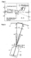
- a film camera in which the stabilization device according to the invention can be used in a preferred manner is shown in Figure 2 schematically from above and in total denoted by 10.
- the film camera has a housing 12, in which the stabilizing device according to the invention arranged together with other components is.
- the optics of the film camera 10 is simplified schematically represented and designated 14.
- the optics 14 defines a constructive optical axis of the film camera 10, which is designated M in FIG.
- the constructive optical axis M in turn defines one below as an actual image section 16 designated image detail. Conveniently, the axis M is at the center this actual image section addressed.
- Target image section is the image detail, the desired by the user. Ie. this one wants this Target image section 18, or its displacement movement, maintained for a certain period of time or for any length of time.
- the appropriate target orientation of the camera in The following also called effective optical axis, is with Z designated.
- Z In the time shown in Figure 1 is the Film camera 10 along its constructive optical axis M, which is different from the original orientation Z differs by a position difference angle R.
- the size of this angle is determined by the user caused by targeted alignment of the camera position difference plus one of the inevitable trembling and Varying of the user caused interference angle.
- the actual horizon of the film camera is determined by the axis M and defines an axis perpendicular thereto K, where through these two axes again spanned a plane is.
- the camera 10 may have another compensating device designated 20 for compensation of the position difference between actual horizon and target horizon, below H designated to have.
- the compensation device 20 is provided here in the image plane 22 of the camera 10 and compensates the horizon difference z. B. by means of appropriate Rotation of the electronic image sensor.
- the position-direction difference R illustrated in FIG is only by a pivoting movement of the film camera 10 causes the intersection of the axes M, Z.
- linear deviations have to be considered, i.e. substantially perpendicular to the target image detail defining axis Z. Such deviations are referred to below as P.
- FIG. 1 shows a preferred embodiment of an im Frame of the device according to the invention usable viewfinder image shown.
- the axis Z is here in the Center of the viewfinder image.
- geometric figures, which in the present embodiment are formed as circles are different Position difference ranges definable, each of which different Functions are assignable.
- the deviation between the axes Z and M is preferably a directional cursor C1 z.
- This area preferably corresponds to one Position difference value range of e.g. 0.7 degrees around the target orientation the optical axis.
- the area function is executed when the directional cursor C1 enters the circle R1 is controlled and held there. She then holds the Target orientation constant, which means a standstill of the image section equivalent.
- the analog range function "Change the current orientation movement" is assigned, which preferably works as follows: the target orientation is first in the direction in which the cursor C1 the circle R1 leaves. Once the cursor is outside for a minimum time of R1, a vector is determined, and preferably as Arrow V is displayed, from the district center to the circle shows. From this moment the position difference range R1 but it will still be displayed.
- the length and direction of the arrow V are a measure of the size and direction of the current target displacement speed the desired image detail, these preferably taking into account the current image angle the optics measured in image section widths per second becomes.
- the arrow length is preferably approximately proportional to the logarithm of the current setpoint speed, where the initial speed is zero or is very low.
- the arrowhead is controlled in any direction and in that way direction and speed the movement of the target image section changed.
- the arrowhead does not follow the cursor C1 directly, but somewhat delayed in time.
- the greater the distance the cursor C1 from the arrowhead is the faster they are tracked so that they are never far from the Cursor C1 removed.
- the below described range R2 only the distance between cursor and range limit of R2.
- the target image section analogous to the camera orientation in any Direction and be relocated at any speed, this shift because of the applied Acceleration algorithms sensitively possible.
- the camera may waver while running during However, this analog range function is not completely suppressed since it is the modification of the velocity vector influenced with.
- an alignment difference range R2 provided. He will be at the helm of the Velocity vector V preferably in the form of a Circle R2 shown, whose radius is preferably variable and equal to half the arrow length, but he expediently not greater than a predetermined maximum value R2m should be dimensioned.
- the discrete range function associated with area R2 is executed when the alignment cursor C1 in this Circle R2 is controlled.
- the area function then stops the instantaneous setpoint speed and setpoint direction of Image section shift constant as long as the cursor is held in this circle R2.
- the display of area R2 may preferably be on request omitted if instead e.g. the cursor C1 on approach to the (now invisible) circle edge or to its Exceeding its color and / or blinking frequency etc. changes accordingly.
- This variable in its position range is that of the user by controlling the cursor C1 in the area always near the cursor R2 in an intuitive way an acceleration of a Image Close-up Motion and into a Uniform Movement can be transferred.
- a position cursor C2 reflects the deviation of the reference point of the image pickup device from a desired position the environment. The impact of this distance with their unavoidable fluctuations should prevail everything considered in extreme telephoto and from the compensation device can be compensated.
- a discrete range function for stabilizing the camera position variations and a position difference range assigned to it which e.g. in the form of a circle P1 in the center of the viewfinder image whose area is a position difference value range from e.g. 8 cm diameter corresponds.
- P1 falls for the sake of oversight with the Circle R1 together.
- the range function passes size and direction of this difference, as already described above, to the compensation device. It will be executed if a e.g. represented by a small square Position cursor C2 by moving the image pickup device to the side and in height in the area P1 controlled and held there.
- P1 preferably during recording breaks a essential assigned a smaller value range, which has the advantage C2 is always close to the center when recording starts from P1 lies.
- the cursor C2 is outside the position difference range P1 in the remaining area P2, the deviation becomes to the reference point of the environment according to an algorithm always again returned to the range limit P1. This matches with moving to the target image detail marking Serving position reference point of the environment with the camera.
- a horizon cursor C3 reflects the deviation of the camera horizon from the target horizon. He will preferably indicated by 2 short lines on the searcher display border, the on an imaginary, going through the display center, Line whose position is analogous to the angle between the Camera horizon and the target horizon is, with the target horizon preferably always horizontally through the viewfinder image center runs.
- a discrete range function for a provided to the real horizon parallel target horizon position It is executed when the horizon cursor C3 means Align the camera around its optical axis in the corresponding position difference range H1 on the viewfinder screen edge is controlled and held there. This area includes e.g. an angle of + - 3 degrees to the desired horizon.
- the Range function then sets the desired image horizon angle to zero. This is then by the compensation device automatically the displayed image horizon parallel to held real horizon, and then its location from shaking and swaying the camera is no longer affected.
- an analog domain function intended for a change in the target horizon position.
- the Rotation and the rotation speed of the target horizon should preferably be about the rotation of the camera around her follow optical axis.
- This analog range function is executed when the horizon cursor C3 is turned of the image pickup device about its optical axis from the belonging to the current horizon position horizon difference area is controlled out. It then changes the target horizon angle the faster, the farther the cursor C3 of the range H1 or H2 is removed. During the execution this analog range function is the wavering the camera with in the movement of the image horizon.
- a discrete range function for a constant maintenance of the current desired horizon position intended is done when the Cursor C3 by aligning the camera with its optical Axis in the corresponding position difference range H2 am Viewfinder image edge controlled and held there. This Area H2 will not change until the nominal horizon of the Ambient horizon displayed.
- the position difference range is preferably on the left and / or right of the viewfinder image center and includes e.g. an angle of + - 2 degrees.
- the discrete range function then holds the current setpoint horizon angle constant. Then automatically the displayed image horizon held parallel to the desired horizon, being its location from the shaking and swaying of the image capture device is not affected.
- position difference areas and discrete range functions for a horizontal or vertical pivot are preferably as described below, by selecting a menu, activated, at the same time the desired maximum swivel speed can be preselected.
- the pivoting preferably starts in the direction in which the cursor C1 is the central area for Picture standstill leaves, with the direction of movement of the Image section on horizontal or vertical movement is limited.
- the start-up is preferably carried out with a constant Acceleration until the preselected swing speed is reached.
- the outlet also takes place with same deceleration acceleration when the cursor returns is led into the central area. After a stop the normal position difference ranges are activated again.
- an alignment difference area is activated and displayed which is preferably over the whole Display extends and its range function the current Movement of the image section keeps constant.
- Such Button can z. B. at a suitable location of the housing be provided of the image pickup device.
- This area are more labeled or with symbols Alignment difference areas superimposed, their area functions System parameters of the image acquisition device, such as white balance, color temperature, gray filter, aperture, Exposure time, activation of position difference ranges with selection of a maximum speed for one Pan, etc. control, if by means of appropriate Aligning the image pickup device selected and e.g. when the key is released.
- an alignment difference range activatable whose boundaries visually superimposed on the viewfinder image and include a substantial part of the viewfinder image and its range function on the one hand the current movement of the image section holds constant and the other running from the position difference indicated by a cursor under evaluation of the current focal length of the optics corresponding image section position determined and on a focusing automatic for focusing on this Forward the part of the image section.
- the rest Alignment difference area is during the key press preferably an analog range function for Relocation of the image section assigned.
- the following are functions for pre-programming and program-controlled execution of an image section progression for movie cameras.
- the pictured image section is completely still, as long as the target position does not change and as long the position difference not that of the compensation device exceeds compensatable values.
- a first position difference range in the form of a cone with e.g. at an angle of 2 degrees the desired position of the optical axis given and this Area assigned the task "Image Cutting Standstill". As long as the position difference values within this Area, the target position data are not changed.
- a second position difference range is defined, that from all the rest of the compensation device compensable position difference values, and this area the task "shifting of the image section" assigned.
- the Target position data changed according to an algorithm in the especially direction and distance of the current position difference regarding the first position difference range.
- the greater the distance to the range limit the larger the speed of the target image shift. This happens preferably after an exponential relationship: at a positional difference of e.g. 2, 3, 4, or 5 degrees relative the target position is the speed of the desired position change then e.g. to 0, 1, 10, or 100 degrees per second set.
- For a positional difference of e.g. 3 degrees to the right of Target image center then becomes the horizontal component of Target position data continuously increased by 1 degree per second.
- the notification of the position difference e.g. realized as follows: To the viewfinder image around, for example, eight arrows are visualized, point their point to the viewfinder image center. These arrows can be in their color and / or brightness and / or flashing frequency are modulated, giving the user from the type of representation of the reference of the position difference to the position difference ranges e.g. as follows is made: as long as the position difference values in the central first position difference range A, the arrows are static green. Their brightness reflects the size and direction of the current position difference value contrary. For a zero position difference all shine Arrows equal to light. For a positional difference of e.g.
- the right arrow shines brighter, the others Arrows correspondingly darker.
- the position difference approaches the range limit of 2 degrees, then the corresponding Arrow yellow and optionally also flashing shown. If the position difference has exceeded the range limit, the corresponding arrow is displayed in red.
- the arrows in the green or keep yellow area are quiet resting and to achieve a non-fluctuating image detail.
- the user also determines when the image section should relocate. For this he aims the binoculars as long after e.g. right until the right arrow turns red, after which the image section starts to move to the right. This happens the faster the faster he does that Binoculars moved to the right. Because with this simple variant the invention, the speed of the image section displacement for speeds greater than zero always depends on the momentary size of the position difference, can not optimally stabilize the frame moving movement done what with binoculars but also not of great importance. Once by appropriate Align the binoculars the arrows back into the green or yellow area are controlled, takes place immediate and overshoot-free picture standstill.
- this simple variant of the invention can also for a film camera recording on chemical film or for a consumer video camera.
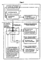
- FIG. 3 is a functional diagram of a simple embodiment an image stabilization according to the invention shown.
- Alignment of the optical axis takes into account what for Consumer binoculars or consumer video cameras quite can be sufficient because of unwanted movements of the optical Axis by far the biggest impact on the Have rest.
- the possible consideration of the position of the imaging device and the horizon position accordingly, d. H. it can each be the same Function diagram are applied.
- 301 sets the target alignment of the optical axis, by z. B. corresponding directional values in a Memory are stored. Their initial value can be arbitrary here be, z. B. 30 degrees East and 10 degrees below the horizon.
- the actual Position of the optical axis determined.
- z. B. a Gyro be used.
- a rotation about the vertical axis of the image pickup device the value of orientation with respect to the direction of the compass changes and a rotation about the transverse axis of the imaging device the value concerning the inclination to the horizon.
- the position difference between actual position and Target position determined and converted in both components, which are compensated by the compensation device can, for. B. in the two angles to be compensated the vertical axis and the transverse axis of the image pickup device.
- the compensation device 304 then compensates for the alignment difference completely and for all frequencies one changing alignment difference, as above already mentioned.
- the core of the invention consists of the area 311 to 315. From a system controller 312, there are two position difference ranges (311) fixed: a central area LDB-1 of 2 degrees around the nominal direction of the optical Axis and remaining area LDB-2 between 2 degrees and 5 degrees around the desired direction of the optical axis.
- the system control is constantly watching in which area the instantaneous alignment difference of the optical axis falls.
- the position difference with respect to Range limits to the user via the message facility 313 communicated so that the user by means of according to the alignment of the image recording device, the position difference steer specifically into one of the areas and there can hold.
- the analogue Range function 315 "displacement / movement" of the target orientation the optical axis called and executed, which the current target orientation of the optical axis the faster the position difference of the limit of the range LDB-2 is removed, the Direction of change from the direction of the position difference is derived to the center of LDB-1.
- the nominal position follows hereby analogous to the orientation of the image recording device. Unintended fluctuations of the position difference, however, go as in conventional solutions, with in the displacement speed one.
- this range feature is used also arbitrary position initial values at commissioning of the image pickup device with non-compensable Position difference values synchronized, since every large position difference tracking the target position at high speed, so that the position difference automatically in the shortest possible time Time is reduced to compensatable values.
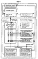
- FIG. 4 is a functional diagram of a more complex one Embodiment of an image stabilization according to the invention, for z. A professional movie camera, shown. In the further description is only on the Differences from the embodiment according to Figure 3 received:
- the main difference is that there are more than two Position difference ranges (five examples here), where some of them are variable in their position and size, such as B.
- This Area is first activated by the system control 415, if the position difference is the central area LDB-2 has left for "image standstill". His situation and that Its range of values is preferably a function of speed and direction of the current displacement speed the desired image position, as previously described.
- the area function 422 is executed, which is the Target coordinates of the target image position, according to the Call of 422 existing target displacement speed, evenly and steadily changed. This uniform movement of the target image section is then completely free from all unwanted position difference fluctuations. This is due to the always present complete compensation of all position difference values Of course, synonymous for the captured image.
- a graphic display 418 with graphic display the position difference ranges LDB 1, 2, 3, 4 ... in the form graphic symbols and graphic display of the position difference provided in the form of cursors (see also description of FIGS. 1 and 2).
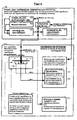
- FIG. 5 shows a functional diagram of a device according to the invention Image stabilization shown, which shows how conventional stabilization devices even without redesign can be modified to the benefits to use the invention.
- Image stabilization shown, which shows how conventional stabilization devices even without redesign can be modified to the benefits to use the invention.
- a conventional stabilizer device is 501 to 505 of group 500.
- this of the position difference range LDB-1 assigned Range function 514 for "image standstill" during the Execution of this feature simply disabled, so he the target image position then no longer changed. The picture section is then unaffected by location fluctuations quiet.
- FIG. 6 shows a functional diagram of a device according to the invention Image stabilization shown, which shows how another variant of a conventional stabilization device be modified without redesign can to take advantage of the invention.
- Image stabilization shown, which shows how another variant of a conventional stabilization device be modified without redesign can to take advantage of the invention.
- a conventional stabilizer device is 603 to 605 of group 600.
- the image section then remains unaffected by Location fluctuations in its movement.
Abstract
Description
Die Erfindung stellt eine Stabilisierungs-Einrichtung für Bildaufnahmegeräte, z. B. eine Filmkamera, ein Fernglas, eine Fotokamera etc., zur Verfügung, die dem Anwender eine Stabilisierung eines Bildausschnitts und/oder eine Stabilisierung einer Bildausschnitts-Verlagerung und optional auch eine Stabilisierung des Ablaufs eines vorprogrammierten Bewegungspfades ermöglicht.The invention provides a stabilization device for Imaging devices, eg. A movie camera, binoculars, a camera, etc., available to the user a Stabilization of an image section and / or stabilization an image shift and optional also a stabilization of the course of a preprogrammed Motion path allows.
Bei einer Vielzahl von Bildaufnahmegeräten ist es zweckmäßig, sowohl Verwacklungsunschärfen bei Einzelbildern als auch unerwünschte Verlagerungen von Einzelbildern einer Bildfolge oder Ungleichmäßigkeiten einer Bildverlagerungs-Bewegung während Schwenks so weit wie möglich zu unterdrücken. Dies trifft vor allem für von Hand geführte Bildaufnahmegeräte zu, die eine Bildfolge aufnehmen, wie z.B. Filmkameras und Ferngläser.In a variety of image capture devices, it is useful both shake blurs in single images as also unwanted displacements of single images Image sequence or nonuniformities of an image shift motion while panning as much as possible to suppress. This is especially true for hand-held imaging devices to record a sequence of pictures, such as Movie cameras and binoculars.
Im Stand der Technik sind hierzu bereits verschiedene Lösungen bekannt.In the prior art, this already different solutions known.
So werden für Filmaufnahmen vor allem Stative eingesetzt, da bis heute nur diese professionellen Ansprüchen an die Bildruhe genüge tun. Ihr Nachteil besteht in ihrer Größe und ihrem großen Gewicht. Deshalb gibt es vor allem für Ferngläser und Videokameras schon seit vielen Jahren Stabilisierungs-Systeme, die in das Bildaufnahmegerät eingebaut sind.For example, tripods are used for filming, because until today only these professional demands on the Picture rest is enough. Their disadvantage is their size and her big weight. That is why there is especially for Binoculars and video cameras have been stabilizing systems for many years, which are built into the image capture device are.
So gibt es im Objektiv des Bildaufnahmegerätes eingebaute oder auf dieses aufsetzbare Stabilisierungs-Systeme, welche mittels steuerbarer optischer Elemente das in der Abbildungsebene abgebildete Bild in dieser verlagern können. Als steuerbare optische Elemente werden variable Prismen oder lateral zur optischen Achse verschiebbare Linsen eingesetzt. Ihre Verlagerung wird von einem Bewegungssensor so gesteuert, dass die durch ein Zittern des Bildaufnahmegerätes verursachten Abbildverlagerungen kompensiert werden. Diese Systeme haben den Vorteil, dass sie auch für Filmkameras verwendet werden können, welche auf chemischem Film aufnehmen.So there are built-in in the lens of the image capture device or on this attachable stabilizing systems, which by means of controllable optical elements that in the image plane pictured image in this can shift. As controllable optical elements are variable prisms or laterally displaced to the optical axis lenses used. Your shift is from a motion sensor so controlled that by a shaking of the image capture device caused image shifts are compensated. These systems have the advantage that they are synonymous for Film cameras can be used, which are based on chemical Take a movie.
Weiterhin gibt es für Bildaufnahmegeräte mit elektronischem Aufnahmesensor, wie beispielsweise Videokameras, Bildstabilisierungs-Systeme, welche den zu verwertenden Bildausschnitt auswählen können. Dieser Bildausschnitt bzw. der ganze Aufnahmesensor wird von einem Bewegungssensor so verlagert, dass den durch ein Zittern des Bildaufnahmegerätes verursachten Abbildverlagerungen in der Sensorebene möglichst exakt gefolgt wird.Furthermore, there are for image recording devices with electronic Recording sensor, such as video cameras, Image stabilization systems, which use the Can select image section. This picture detail or the whole recording sensor is a motion sensor so shifts that by shaking the image capture device caused image shifts in the sensor plane is followed as exactly as possible.
Diese optischen und elektronischen Stabilisierungs-Systeme arbeiten im wesentlichen nach dem gleichen Regelungs-Prinzip. Es wird eine gewünschte Soll-Lage oder Folge von Soll-Lagen des Bildaufnahmegerätes und damit eine gewünschte Bildausschnitts-Lage oder Bildausschnitts-Folge, mit der tatsächlichen jeweiligen Ist-Lage des Bildaufnahmegerätes verglichen und daraus eine Lagedifferenz ermittelt. Zur technischen Realisation dieser Ermittlung der Lagedifferenz sind bereits Lösungen vielfältigster Art bekannt, welche z.B. Beschleunigungs-Sensoren, Kreiselsysteme, Winkelmeß-Vorrichtungen usw. verwenden. Die von einer jeweiligen Lagedifferenz verursachte Abweichung zum gewünschten Bildausschnitt wird von einer der oben beschriebenen Kompensations-Vorrichtungen kompensiert.These optical and electronic stabilization systems work essentially according to the same control principle. It will be a desired target position or sequence of Target positions of the image recording device and thus a desired Image section position or image sequence, with the actual actual position of the image pickup device compared and determined therefrom a position difference. For the technical realization of this determination of Positional differences are already known solutions of many kinds, which e.g. Acceleration sensors, gyro systems, Use angle measuring devices, etc. The one by one respective position difference caused deviation from the desired Image section is taken from one of the above Compensation devices compensated.
Sowohl die optischen als auch die elekronischen Stabilisierungs-Systeme unterdrücken nach diesem Regelmechanismus sehr gut alle unerwünschten hochfrequenten Lagedifferenzen. Dies erfolgt jedoch aus prinzipiellen Gründen nicht für die niederfrequenten Lagedifferenzen, welche vor allem vom Anwender durch seine unervermeidbaren, langsamen Schwankbewegungen verursacht werden, wenn er z.B. eine Filmkamera oder ein Fernglas mit der Hand führt. Diese langsamen Bewegungen dürfen, zumindest ab einer gewissen Größe, nicht kompensiert werden, da es anderenfalls nicht möglich wäre, Bildfolgen während einer gewollten Schwenkbewegung des Bildaufnahmegerätes aufzunehmen. Herkömmliche Stabilisations-Systeme haben keine Möglichkeit, eindeutig zu unterscheiden, ob eine langsame Bewegung des Bildaufnahmegerätes über eine gewisse Grenze hinaus unerwünscht, oder gewollt ist.Both the optical and electronic stabilization systems suppress this control mechanism very good all unwanted high-frequency position differences. However, this is not done for reasons of principle for the low frequency differences, which are mainly from the user through its unavoidable, slow Waves are caused when he e.g. a Film camera or binoculars with the hand guides. These slow movements may, at least from a certain Size, can not be compensated, otherwise it will not would be possible, image sequences during a desired pivotal movement of the image capture device. conventional Stabilization systems have no way to be unique to distinguish whether a slow movement of the imaging device undesirable beyond a certain limit, or wanted.
Keines der bisher bekannten Systeme kann alle Anforderungen an ein ideales Stabilisierungs-System erfüllen. Ein Stativ liefert nur bei einem ruhigen Untergrund einen perfekt ruhigen Bildausschnitt, wohingegen völlig gleichmäßige Schwenks nur sehr schwer zu erreichen sind, da die Schwenkgeschwindigkeit in der Praxis von der Größe des Drucks auf den Schwenkhebel abhängt. Die bekannten optischen und elektronischen Stabilisierungs-Systeme unterdrücken nur das unerwünschte höherfrequente Zittern sehr gut, sie können aber keinen völlig ruhig stehenden Bildausschnitt oder eine Stabilisierung eines Bewegungspfades, wie z.B. bei einem horizontalen Schwenk erforderlich, erreichen.None of the previously known systems can meet all requirements to fulfill an ideal stabilization system. One Tripod provides only on a quiet surface a perfect quiet picture section, whereas completely uniform Pans are very hard to reach because of the Pivoting speed in practice on the size of the Pressure on the pivot lever depends. The well-known optical and suppress electronic stabilization systems only the unwanted higher-frequency tremor very good, but you can not completely calm picture frame or a stabilization of a movement path, such as. required for a horizontal swing, reach.
Die Aufgabe der vorliegenden Erfindung besteht daher vor allem darin, eine Stabilisierungs-Einrichtung zur Verfügung zu stellen, mit der sowohl ein völlig ruhig stehender Bildausschnitt von beliebiger Dauer ohne unerwünschte Zitter- und Schwankbewegungen als auch eine völlig gleichmäßige Bildverlagerungs-Bewegungen für z.B. Schwenks mittels handgeführter Bildaufnahmegräte ermöglicht wird, wobei der Anwender die Kontrolle darüber erhält, ob, wann und wie sich ein Bildausschnitt verlagern soll.The object of the present invention therefore exists All in all, a stabilization facility is available to ask, with both a completely calm standing Image section of any duration without unwanted trembling and fluctuations as well as a completely uniform Image shift movements for e.g. Pans by means of hand-held Bildaufnahmegräte is possible, the Users gain control over whether, when and how a picture should shift.
Diese Aufgabe wird gelöst durch eine Stabilisierungseinrichtung
mit den Merkmalen des Patentanspruchs 1 sowie ein
Verfahren mit den Merkmalen des Patentanspruchs 10.This object is achieved by a stabilization device
with the features of
Durch das Vorsehen einer Mitteilungs-Einrichtung gemäß Anspruch
1 kann mittels Ausrichten des Bildaufnahmegerätes
vom Anwender die Lagedifferenz zwischen Ist-Lage und Soll-Lage
z.B. in der Nähe des Lagedifferenz-Wertes Null gehalten
werden. So kann vermieden werden, dass die Lagedifferenz
ungewollt, und aufgrund des stabilisierten Bildes unbemerkt,
langsam immer mehr von Null abweicht. Bei herkömmlichen
Stabilisierungsvorrichtungen hat der Anwender
keine Möglichkeit, diese Lagedifferenz zu erkennen und
entsprechende Korrekturen in der Ausrichtung des Bildaufnahmegeräts
einzuleiten. Dies hatte zur Folge, dass bei
Überschreiten einer bestimmten Lagedifferenz, eine Bildverlagerung
unvermeidlich war, da die Stabilisierungs-Vorrichtung
eine derartige Lagedifferenz als gewünschte
Verlagerung des Bildausschnittes interpretieren musste.By providing a message device according to
Außerdem kann erfindungsgemäß die Amplitude der ungewollten langsamen Schwankungen der Lagedifferenz aufgrund der Rückkopplung über die Mitteilungs-Einrichtung an den Anwender auf kleinere Werte beschränkt werden, als dies ohne diese Rückkoppplung der Fall ist. Auf diese Weise können herkömmliche Stabilisierungs-Vorrichtungen in ihrer Wirkung bereits erheblich verbessert werden. Es können ferner auch Stabilisierungs-Vorrichtungen mit einem gegenüber herkömmlichen Lösungen verkleinerten Stabilisierungsbereich eingesetzt werden.In addition, according to the invention, the amplitude of the unwanted slow fluctuations in the positional difference due to the Feedback via the message facility to the user be limited to smaller values than this without this feedback is the case. That way you can conventional stabilizing devices in their effect already be significantly improved. It can also also stabilizing devices with one opposite conventional solutions reduced stabilization range be used.
Die Mitteilung der Abweichung der Lagedifferenz bezüglich eines vorgegebenen Wertes oder Bereiches kann auf vielfältige Weise, wie z.B. auch akustisch erfolgen. Vorzugsweise besteht die Mitteilungs-Einrichtung aber aus einer optischen Anzeige.The message of the deviation of the position difference concerning of a given value or range can be varied Way, e.g. also acoustically. Preferably However, the message device consists of an optical Display.
So kann die Abweichung der Lagedifferenz von dem Wert Null oder von den Grenzen eines Lagedifferenz-Bereichs z.B. mittels am Sucherbildrand angeordneter Pfeile mitgeteilt werden. Die Größe der Abweichung kann z.B durch die Helligkeit und/oder Farbe und/oder Blinkfrequenz der Pfeile anzeigt werden. Diese Art der Anzeige hat den Vorteil, dass sie dass Sucherbild nicht abdeckt, wie dies insbesondere bei Ferngläsern wünschenswert ist.Thus, the deviation of the position difference from the value zero or from the boundaries of a position difference range, e.g. communicated by means arranged on the viewfinder edge arrows become. The size of the deviation can be, for example, by the brightness and / or color and / or blink frequency of the arrows to be displayed. This type of ad has the advantage that it does not cover the viewfinder image, as this particular in binoculars is desirable.
Vorteilhafterweise erfolgt die Anzeige, insbesondere bei Filmkameras, auf grafische Weise mittels eines elektronischen Displays, dessen Anzeige dem Sucherbild überlagert wird. Die grafische Anzeige hat den Vorteil, dass der Anwender einen Lagedifferenz-Wert in einfacher Weise noch genauer steuern kann und dass übersichtlich auch mehrere Lagedifferenz-Arten mit ihren vorgebbaren Lagedifferenz-Werten oder -Wertebereichen angezeigt werden können, wie dies für professionelle Anwendungen der Erfindung wünschenswert ist.Advantageously, the display takes place, in particular at Cinematographic cameras, graphic by electronic means Displays whose display overlays the viewfinder image becomes. The graphical display has the advantage that the user a position difference value in a simple way yet can control more precisely and that clearly also several Position difference types with their predefinable position difference values or value ranges can be displayed, such as this is desirable for professional applications of the invention is.
Vorteilhafte Ausgestaltungen der Erfindung sind Gegenstand der Unteransprüche.Advantageous embodiments of the invention are the subject the dependent claims.
Gemäß einer bevorzugten Ausführungsform der Stabilisierungs-Einrichtung sind den Sollbildausschnitt definierende Parameter, wie Soll-Ausrichtung der optischen Achse und deren Soll-Bewegung etc., über Algorithmen vorgebbar, welche für die wichtigsten Stabilisierungs-Aufgaben, wie z.B. Bildstillstand, gleichförmige Bewegung, Beschleunigung und Abbremsen während Schwenks, von der Lagedifferenz vorzugsweise vollkommen unabhängig sind, solange die Lagedifferenz-Werte innerhalb eines vorgebbaren, der jeweiligen Aufgabe zugeordneten, Lagedifferenz-Wertebereichs liegen. Natürlich kann es auch Aufgaben und diesen zugeordnete Lagedifferenz-Bereiche geben, für welche die Lagedifferenz-Werte mit in die Vorgabe der Soll-Lage eingehen sollen, wie z.B. für die Aufgabe, den Bildausschnitt analog zur Ausrichtung des Bildaufnahmegerätes zu verlagern. According to a preferred embodiment of the stabilization device are defining the target image section Parameters, such as target orientation of the optical axis and their target movement etc., can be specified via algorithms, which for the most important stabilization tasks, such as Picture standstill, uniform motion, acceleration and Slowing down during panning, preferably from the positional difference are completely independent, as long as the position difference values within a specifiable, the respective Task assigned, position difference value range are. Of course, it can also do tasks and their assigned position difference ranges for which the position difference values should be included in the specification of the target position, such as. for the task, the image section analogous to Move the orientation of the image capture device.
Weiterhin erweist es sich als vorteilhaft, den einer Aufgabe zugeordneten Lagedifferenz-Bereich größer vorzugeben, als der Umfang der vom Anwender durch sein Zittern und Schwanken bedingten Lagedifferenz-Schwankamplitude oder Störungs-Wertemenge. So kann ein der Aufgabe "Bildstillstand" zugeordneter Lagedifferenz-Bereich z.B. +-2 Grad in jeder Richtung relativ zur Soll-Ausrichtung der konstruktiven optischen Achse des Bildaufnahmegerätes betragen, was um einiges größer ist, als eine typische, vom Anwender verusachte, Lagedifferenz-Schwankamplitude der optischen Achse.Furthermore, it proves to be advantageous to a task specify the assigned position difference range larger, as the scope of the user by his shaking and Fluctuate positional differential fluctuation amplitude or Interference of values. So one of the task "picture standstill" associated position difference range e.g. + -2 degrees in each direction relative to the target orientation of the constructive optical axis of the image recording device, which is a lot bigger than a typical user Veruspens, position difference oscillation amplitude of the optical Axis.
Der Anwender kann jetzt gezielt einen Bildausschnitts-Stillstand bewirken, indem er den Lagedifferenzwert durch entsprechendes Ausrichten des Bildaufnahmegerätes in diesen der Aufgabe "Bildstillstand" zugeordneten Bereich steuert und ihn dort hält, was ihm aufgrund der Rückkopplung über die Mitteilungs-Einrichtung und der Größe des Lagedifferenzbereichs für Bildstillstand leicht und für beliebig lange Zeit möglich ist. Die Soll-Lagedaten, z.B. die Soll-Lagedaten der konstruktiven optischen Achse, werden dann konstant gehalten, auch wenn die Lagedifferenzwerte aufgrund eines Zitterns oder Schwankens des Anwenders z.B. innerhalb +- 1 Grad schwanken. Da außerdem vorschlagsgemäß ständig die Auswirkung jeglicher Lagedifferenz auf den abgebildeten Bildausschnitt von einer Kompensations-Vorrichtung, so weit technisch irgend möglich, vollständig und frequenzunabhängig kompensiert wird, wird z.B. der Einfluß des unerwünschten Schwankens der konstruktiven optischen Achse auf einen Bildstillstand vollständig eliminiert. Damit ist die wichtigste Aufgabe einer Stabilisierungs-Einrichtung gelöst (siehe auch FlußDiagramm in Figur 3). The user can now target a picture cut-off effect by taking the position difference value through corresponding alignment of the image recording device in this assigned to the "image standstill" task controls and holds him there, giving him feedback about the notification facility and the size of the Position difference range for image standstill easy and for Any length of time is possible. The desired location data, e.g. the desired position data of the constructive optical axis, are then kept constant, even if the position difference values due to a trembling or wavering of the user e.g. fluctuate within + - 1 degree. In addition, as proposed constantly the effect of any positional difference on the pictured image section of a compensation device, as far as technically possible, is fully and frequency independent compensated is e.g. the influence of unwanted fluctuation of constructive optical axis to a picture standstill completely eliminated. This is the most important task of a Stabilization device solved (see also flow diagram in FIG. 3).
Soll der Bildausschnitt verlagert werden, steuert der Anwender den Lagedifferenzwert aus dem für "Bildstillstand" reservierten Bereich heraus und in einen z.B. für analoge Verlagerung des Bildausschnitts vorgesehenen Lagedifferenzbereich, wie er weiter unten beschrieben wird.If the image section is to be relocated, the user controls the position difference value from the for "picture standstill" reserved area and in a e.g. for analog Displacement of the image section provided position difference range, as described below.
Gemäß einer weiteren bevorzugten Ausführungsform der erfindungsgemäßen Stabilisierungs-Einrichtung für z.B. professionelle Filmkameras werden gleichzeitig mehrere Lagedifferenz-Arten berücksichtigt. Vorteilhaft hierbei ist, dass bei Einsatz der zuvor beschriebenen erfindungsgemäßen Prinzipien ein von allen ungewollten Bewegungen jeglicher Richtung völlig unbeeinflusster Bildausschnitt realisierbar ist. Der zusätzlich technische Aufwand ist im Vergleich zum Mindestaufwand relativ gering.According to another preferred embodiment of the invention Stabilizer for e.g. professional Film cameras simultaneously become multiple position difference types considered. The advantage here is that when using the invention described above Principles one of all unwanted movements of any Direction completely uninfluenced image detail feasible is. The additional technical effort is compared to the minimum cost relatively low.
Hierzu wird vorzugsweise mittels bekannter technischer Mittel nicht nur die Ausrichtungs-Differenz der konstruktiven optischen Achse zu einer Soll-Ausrichtung, sondern auch die Positions-Differenz eines Bezugspunktes des Bildaufnahmegerätes zu einer Soll-Position und vorzugsweise auch die Horizont-Differenz des Bildaufnahmegrätes zu einer Soll-Horizontlage ermittelt. Der Vorteil einer Stabilisierung des Bildhorizonts kommt vor allem bei Filmaufnahmen zum Tragen. Der Vorteil, den eine Berücksichtigung der Positions-Differenz bringt, liegt insbesondere darin, dass dann auch Aufnahmen mit extremen Telebrennweiten stabilisiert werden können: ist z.B. der aufgenommene Bildausschnitt nur noch 20 cm breit und das Bildaufnahmegerät schwankt um 1 cm zur Seite hin, so verlagert sich der Bildausschnitt ungewollt bereits um 5% der Bildbreite. Die Bezugspunkt-Differenz wird vorzugsweise nur in der Ebene senkrecht zur Ausrichtung der optischen Achse ermittelt, da unerwünschte Verlagerungen des Bildaufnahmegerätes entlang der optischen Achse sich nur bei extremen Nahaufnahmen des aufgenommenen Bildausschnitts auswirken.For this purpose, preferably by means of known technical Means not only the alignment difference of the constructive optical axis to a target orientation, but also the position difference of a reference point of the image recording device to a desired position and preferably also the horizon difference of the image recording device to a Target horizon position determined. The advantage of stabilization The horizon of the picture comes mainly with filming to carry. The advantage of having a consideration the positional difference is, in particular, that then also stabilizes recordings with extreme Telebrennweiten can be: is e.g. the captured image section only 20 cm wide and the imaging device varies by 1 cm to the side, so shifts the Image section unwanted already by 5% of the image width. The Reference point difference is preferably only in the plane determined perpendicular to the alignment of the optical axis, because unwanted displacements of the imaging device along the optical axis only at extreme close-ups the captured image.
Die Kompensations-Vorrichtung ist zweckmäßigerweise in der Lage, die Auswirkungen einer jeden der ermittelten Lagedifferenz-Arten auf den aufgenommenen Bildausschnitt möglichst vollständig und frequenzunabhängig zu kompensieren. Für die Kompensation der Positions-Differenz erfolgt dies vorzugsweise durch eine Näherungslösung, indem aus dem Wert der Positions-Differenz und der momentanen Entfernungseinstellung der Optik ein Winkel berechnet wird, welcher zum Wert der ermittelten Ausricht-Differenz addiert wird, so dass die Kompensations-Vorrichtung nur noch zwei Lagedifferenz-Arten kompensieren muß. Der Winkel ergibt sich aus W = arctan [Bezugspunkt-Differenz / Entfernung]. Für die Kompensation der Horizont-Differenz wird, falls vorhanden, vorzugsweise der ganze elektronische Bildsensor gedreht oder eine Elektronik zur Drehung des ausgewerteten Bildausschnitts auf dem Bildsensor eingesetzt, da eine Drehung mittels optischer Elemente aufwändig ist.The compensation device is expediently in the Able, the impact of each of the detected location difference types on the recorded image as possible completely and independently of the frequency. This is done for the compensation of the position difference preferably by an approximate solution, from the Value of the position difference and the current distance setting the optics is calculated an angle which added to the value of the determined alignment difference so that the compensation device only has two more Must compensate position difference types. The angle gives from W = arctan [reference point difference / distance]. For the compensation of the horizon difference, if present, preferably the whole electronic image sensor rotated or electronics for rotation of the evaluated Image section on the image sensor used as a Rotation is complicated by means of optical elements.
Für jede der drei Lagedifferenz-Arten wird vorzugsweise deren von der Kompensations-Vorrichtung kompensierbare Lagedifferenz-Gesamt-Wertemenge in mehrere Lagedifferenz-Bereiche unterteilt, welchen unterschiedliche Bereichs-Funktionen zur Lösung einer jeweiligen Stabilisierungs-Aufgabe oder für sonstige Steuerzwecke zugeordnet sind. Diese Bereichsfunktionen werden ausgeführt, solange sich die entsprechende Lagedifferenz innerhalb des entsprechenden Lagedifferenz-Bereichs befindet, wobei dies vorzugsweise von Mindestaufenthaltszeiten abhängig ist. Dies hat den Vorteil, dass Bereichsfunktionen nicht versehentlich ausgeführt bzw. beendet werden, wenn beispielsweise unbeabsichtigt aufgrund einer Zitter- oder Schwankungsbewegung ein Lagedifferenzbereich nur für kurze Zeit verlassen wird.For each of the three position difference types is preferred their compensated by the compensation device position difference total value set in several position difference ranges divided which different area functions to solve a particular stabilization task or assigned for other tax purposes. These range functions are executed as long as the corresponding position difference within the corresponding Position difference range is, this being preferred depends on minimum stay. this has the advantage that range functions are not accidental be executed or terminated, for example, if unintentional due to a jitter or fluctuation movement leave a position difference range only for a short time becomes.
Vorzugsweise werden außerdem die höherfrequenten Schwankungen der Lagedifferenz-Werte, mit Ausnahme der an die Kompensations-Vorrichtung geleiteten Werte, unterdrückt, was den Vorteil hat, dass ein schnelles Zittern einer angezeigten Lagedifferenz weniger sichtbar ist bzw. in der Darstellung geglättet wird und daher die Lagedifferenz für den Anwender, der ein mit der Erfindung ausgestattetes Bildaufnahmegerät von Hand hält, leichter steuerbar ist.In addition, the higher-frequency fluctuations are preferred the position difference values, with the exception of the Compensation device guided values, suppressed, which has the advantage of being a quick tremor of a displayed Position difference is less visible or in the Representation is smoothed and therefore the position difference for the user who is equipped with the invention Hand-held imaging device is easier to control.
Für spezielle Bildaufnahmegeräte, wie etwa professionelle Filmkameras, sind vorzugsweise entsprechend den wichtigsten Stabilisierungs-Aufgaben folgende Lagedifferenz-Bereiche und diesen zugeordnete diskrete Bereichs-Funktionen zur Vorgabe der Soll-Bildausschnittslage vorgesehen, in deren Ergebnis der jeweilige Lagedifferenzwert nicht mit eingeht (nur die Tatsache, dass sich der aktuelle Lagedifferenzwert in einem bestimmten Lagedifferenz-Bereich befindet, wird berücksichtigt), so dass ungewollte Schwankungen des Bildaufnahmegerätes ohne Auswirkung auf den abgebildeten Bildausschnitt bleiben:
- Stillstand des Bildausschnitts-Zentrums,
- Beibehaltung der momentanen Bewegung des Bildausschnitts-Zentrums,
- Beibehaltung eines gewünschten Bildhorizonts,
- Beschränkung der Bewegung auf Vorgabewerte und Maximalwerte,
- Beschleunigung der Bewegung bei vorgegebener Bewegungsrichtung,
- Ausführung eines vorprogrammierten Bewegungsablaufs, mit Anweisungs-Mitteilung.
- Standstill of the image section center,
- Maintaining the current movement of the image detail center,
- Maintaining a desired image horizon,
- Restrict movement to default values and maximum values,
- Acceleration of movement at a given direction of movement,
- Execution of a preprogrammed motion sequence, with instruction message.
Hiermit können die drei wichtigsten Aufgaben einer Stabilisierungs-Einrichtung für eine Filmkamera gelöst werden, nämlich eine von allen ungewollten Bewegungen der Filmkamera befreite Aufnahme eines still stehenden oder sich gleichmäßig bewegenden Bildausschnitts oder die Aufnahme während eines horizontalen Schwenks mit stetigem Anlauf, gleichmäßigem Verlauf und stetigem Auslauf.Hereby, the three main tasks of a stabilization facility to be solved for a movie camera, namely one of all unwanted movements of the film camera Exempt recording of a still or self evenly moving picture section or the picture during a horizontal panning with steady start, uniform course and steady spout.
Außerdem sind zur Bildausschnitts-Verlagerung analog zur Ausrichtung des Bildaufnahmegerätes Lagedifferenz-Bereiche und diesen zugeordnete analoge Bereichs-Funktionen zur Vorgabe der Soll-Bildausschnittslage vorgesehen, in deren Ergebnis der jeweilige Lagedifferenzwert mit eingeht, so dass Bewegungen bzw. Schwankungen des Bildaufnahmegerätes sich auf den abgebildeten Bildausschnitt mit auswirken:
- Änderung der momentanen Bewegung des Bildausschnitts-Zentrums.
- Änderung des momentanen Bildhorizonts.
- Änderung des Positions-Bezugspunktes des Bildaufnahmegerätes.
- Change of the current movement of the image detail center.
- Change of the current picture horizon.
- Change of the position reference point of the image acquisition device.
Da Änderungen einer Bewegung meistens nur während einer sehr kurzen Zeit erfolgen, fallen schwankungsbedingte Unregelmäßigkeiten nur wenig auf, so dass der Vorteil einer z.B. analog zur Ausrichtung des Bildaufnahmegrätes steuerbaren Änderung von Geschwindigkeit und Richtung einer Bildausschnittsverlagerung überwiegt. Because changes of a movement mostly only during one occur very short time, fall fluctuation-related irregularities little on, so the advantage of a e.g. controllable analogous to the orientation of the Bildaufnahmegrätes Change of speed and direction of a Image excursion outweighs.
Zur Mitteilung der drei Lagedifferenz-Arten bezüglich der Lagedifferenz-Bereiche wird vorzugsweise ein optisches Display eingesetzt, auf dem vorzugsweise sowohl die drei Lagedifferenz-Arten und deren Komponenten, als auch die den unterschiedlichen Aufgaben zugeordneten Lagedifferenz-Bereiche in grafischer Form angezeigt werden. Für Filmkameras mit einem optischen Sucherbild kann das Displaybild diesem Sucherbild z.B. über ein Prisma optisch überlagert werden. Bei Videokameras wird vorzugsweise das bereits vorhandene Sucherbild-Display verwendet.To communicate the three position difference types with respect to the Position difference ranges is preferably an optical Display used on which preferably both the three Position difference types and their components, as well as the Position difference areas assigned to different tasks be displayed in graphic form. For movie cameras with an optical viewfinder image, the display image this viewfinder image e.g. optically superimposed over a prism become. For video cameras, this is preferably already existing viewfinder screen display used.
Folgend werden bevorzugte Ausgestaltungen der Erfindung,
insbesondere unter Darstellung der oben angeführten diskreten
und analogen Bereichs-Funktionen, deren Lagedifferenz-Bereiche
und deren Anzeige beschrieben, wobei Bezug
auf die Figuren 1 bis 6 genommen wird. Hierbei zeigt bzw.
zeigen:
Es versteht sich, dass die vorstehend benannten und die nachstehend noch zu erläuternden Merkmale nicht nur in den jeweils angegebenen Kombination, sondern auch in anderen Kombinationen oder in Alleinstellung verwendbar sind, ohne den Rahmen der vorliegenden Erfindung zu verlassen.It is understood that the above and the hereinafter to be explained features not only in the each specified combination, but also in others Combinations or alone, without to leave the scope of the present invention.
Eine Filmkamera, bei welcher die erfindungsgemäße Stabilisierungs-Einrichtung
in bevorzugter Weise einsetzbar ist,
ist in Figur 2 schematisch von oben dargestellt und insgesamt
mit 10 bezeichnet. Die Filmkamera weist ein Gehäuse
12 auf, in dem die erfindungsgemäße Stabilisierungs-Einrichtung
zusammen mit weiteren Komponenten angeordnet
ist. Die Optik der Filmkamera 10 ist schematisch vereinfacht
dargestellt und mit 14 bezeichnet. Die Optik 14 definiert
eine konstruktive optische Achse der Filmkamera
10, welche in Figur 2 mit M bezeichnet ist. Die konstruktive
optische Achse M definiert ihrerseits einen im folgenden
als Ist-Bildausschnitt 16 bezeichneten Bildausschnitt.
Zweckmäßigerweise ist die Achse M auf die Mitte
dieses Ist-Bildausschnitts gerichtet. Unter Ist-Bildausschnitt
wird im folgenden der Bildausschnitt verstanden,
der von der Kamera dann aufgenommen wird, bzw. im
Sucherbild der Kamera vorliegt, wenn keine Kompensation
bzw. Stabilisierung des Bildes mittels noch zu erläuternden
Kompensationsvorrichtungen der Filmkamera ausgeführt
wird. Der Ist-Bildausschnitt ist somit auch als der Bildausschnitt
zu verstehen, dessen Mitte durch die konstruktive
optische Achse M definiert ist. Es sei zu verstehen
gegeben, dass der Begriff "Ist-Bildausschnitt" gewissermaßen
einen "virtuellen" Bildausschnitt bezeichnet, welcher
tatsächlich durch die optische Einrichtung 10 in der Regel
nicht zu beobachten bzw. aufzunehmen ist.A film camera in which the stabilization device according to the invention
can be used in a preferred manner,
is shown in Figure 2 schematically from above and in total
denoted by 10. The film camera has a
Weiterhin wird davon ausgegangen , dass ein mit 18 bezeichneter
Soll-Bildausschnitt der Bildausschnitt ist, der
vom Anwender gewünscht wird. D. h. dieser möchte diesen
Soll-Bildausschnitt 18, bzw. dessen Verlagerungsbewegung,
über einen bestimmten Zeitraum bzw. beliebig lange beibehalten.
Die entsprechende Soll-Ausrichtung der Kamera, im
Folgenden auch wirksame optische Achse genannt, ist mit Z
bezeichnet. Im in Figur 1 dargestellten Zeitpunkt ist die
Filmkamera 10 entlang ihrer konstruktiven optischen Achse
M ausgereichtet, welche sich von der ursprünglichen Ausrichtung
Z um einen Lagedifferenz-Winkel R unterscheidet. Furthermore, it is assumed that a denoted by 18
Target image section is the image detail, the
desired by the user. Ie. this one wants this
Die Größe dieses Winkels ergibt sich aus der vom Anwender durch gezieltes Ausrichten der Kamera verursachten Lagedifferenz plus einem vom unvermeidbaren Zittern und Schwanken des Anwenders verursachten Störwinkels.The size of this angle is determined by the user caused by targeted alignment of the camera position difference plus one of the inevitable trembling and Varying of the user caused interference angle.
Mittels einer der Optik 14 vorgeschalteten ersten Kompensations-Vorrichtung
19 ist diese Lagedifferenz R kompensierbar.
Das heißt, die wirksame optische Achse der Filmkamera
in dem in Figur 1 dargestellten Zeitpunkt ist Z,
obwohl die konstruktive optische Achse M ist.By means of a
Derartige Kompensations- bzw. Bildverlagerungs-Vorrichtungen wie sie hier mit 19 bezeichnet sind, sind an sich bekannt und werden daher nicht weiter erläutert.Such compensation or image shifting devices as they are here designated 19, are on are known and will therefore not be explained further.
Senkrecht zur Achse Z und durch den Schnittpunkt der Achsen
M, Z in der Bildverlagerungs-Vorrichtung 18 verläuft
eine weitere Achse X, wobei eine durch die Achsen X und Z
aufgespannte Ebene den Soll-Horizont des Soll-Bildausschnitts
18 beschreibt.Perpendicular to the axis Z and through the intersection of the axes
M, Z in the
Der Ist-Horizont der Filmkamera wird durch die Achse M und eine hierzu senkrecht verlaufende Achse K definiert, wobei durch diese beiden Achsen wieder eine Ebene aufgespannt ist.The actual horizon of the film camera is determined by the axis M and defines an axis perpendicular thereto K, where through these two axes again spanned a plane is.
Der Zusammenhang zwischen Soll-Horizont und Ist-Horizont sei ebenfalls anhand eines einfachen Beispiels dargestellt: Geht man davon aus, dass die Achsen M, Z und X in der Zeichenebene der Figur 2, d.h. horizontal, verlaufen, und weist lediglich die Achse K eine Komponente senkrecht zu dieser Zeichenebene auf, führt dies dazu, dass der Soll-Horizont ebenfalls in der Zeichenebene, also horizontal, verläuft, der Ist-Horizont jedoch schräg hierzu, wie weiter unten unter Bezugnahme auf Fig. 1 weiter verdeutlicht werden wird.The relationship between the desired horizon and the actual horizon is also illustrated by a simple example: Assuming that the axes M, Z and X in the drawing plane of Figure 2, i. horizontal, run, and only the axis K has a component perpendicular to this drawing level, this leads to the fact that the Target horizon also in the drawing plane, ie horizontal, runs, the actual horizon but obliquely to this, like further explained below with reference to FIG. 1 will be.
Die Kamera 10 kann eine weitere, mit 20 bezeichnete Kompensationsvorrichtung
zur Kompensation der Lagedifferenz
zwischen Ist-Horizont und Soll-Horizont, im Folgenden mit
H bezeichnet, aufweisen. Die Kompensationsvorrichtung 20
ist hier in der Abbildebene 22 der Kamera 10 vorgesehen
und kompensiert die Horizontdifferenz z. B. mittels entsprechender
Drehung des elektronischen Bildsensors.The
Die in Figur 1 dargestellte Lage-Richtungs-Differenz R
wird lediglich durch eine Schwenkbewegung der Filmkamera
10 um den Schnittpunkt der Achsen M, Z bewirkt. In der Realität
sind auch lineare Abweichungen zu berücksichtigen,
d.h. im Wesentlichen senkrecht zu der den Soll-Bildausschnitt
definierenden Achse Z. Derartige Abweichungen
werden im Folgenden als P bezeichnet.The position-direction difference R illustrated in FIG
is only by a pivoting movement of the
In Figur 1 ist eine bevorzugte Ausführungsform eines im Rahmen der erfindungsgemäßen Vorrichtung verwendbaren Sucherbildes dargestellt.FIG. 1 shows a preferred embodiment of an im Frame of the device according to the invention usable viewfinder image shown.
In dem Sucherbild gemäß Figur 1 erkennt man zunächst die Achsen Z und M. Die Achse Z befindet sich hierbei in der Mitte des Sucherbildes. Mittels im Sucherbild darstellbarer geometrischer Figuren, welche im vorliegenden Ausführungsbeispiel als Kreise ausgebildet sind, sind verschiedene Lagedifferenzbereiche definierbar, denen jeweils unterschiedliche Funktionen zuordnenbar sind. In the viewfinder image according to FIG. 1, one first recognizes the Axes Z and M. The axis Z is here in the Center of the viewfinder image. By means of display in the viewfinder image geometric figures, which in the present embodiment are formed as circles are different Position difference ranges definable, each of which different Functions are assignable.
Für die Anzeige der Ausrichtungsdifferenz, d. h. der Abweichung zwischen den Achsen Z und M, wird vorzugsweise ein Richtungs-Cursor C1 z. B. in Form eines evtl. blinkenden, kleinen Kreuzes angezeigt. Er wird vorzugweise im Zentrum des Sucherdisplays angezeigt, wenn die momentane Ausrichtungsdifferenz gleich Null ist.For the display of the registration difference, i. H. the deviation between the axes Z and M, is preferably a directional cursor C1 z. B. in the form of a possibly flashing, small cross displayed. He is preferably in the Center of the viewfinder display when the current Alignment difference is zero.
Im Zentrum des Displays wird ein Lagedifferenz-Bereich R1 für die diskrete Bereichsfunktion "Stillstand des Bildausschnitts-Zentrums", vorzugsweise in Form eines Kreises, abgebildet. Dieser Bereich entspricht vorzugsweise einem Lagedifferenz-Wertebereich von z.B. 0,7 Grad um die Soll-Ausrichtung der optischen Achse. Die Bereichs-Funktion wird ausgeführt, wenn der Richtungs-Cursor C1 in den Kreis R1 gesteuert und dort gehalten wird. Sie hält dann die Soll-Ausrichtung konstant, was einem Stillstand des Bildausschnittes entspricht.At the center of the display is a position difference range R1 for the discrete area function "Standstill of the image detail center", preferably in the form of a circle, displayed. This area preferably corresponds to one Position difference value range of e.g. 0.7 degrees around the target orientation the optical axis. The area function is executed when the directional cursor C1 enters the circle R1 is controlled and held there. She then holds the Target orientation constant, which means a standstill of the image section equivalent.
Wird der Cursor C1 aus dem Bereich R1 herausgesteuert, so gerät er in den restlichen Bereich R3, dem vorzugsweise die analoge Bereichsfunktion "Änderung der momentanen Ausrichtungs-Bewegung" zugeordnet ist, welche vorzugsweise wie folgt arbeitet: die Soll-Ausrichtung wird zuerst in der Richtung bewegt, in welcher der Cursor C1 den Kreis R1 verläßt. Sobald der Cursor für eine Mindestzeit außerhalb von R1 ist, wird ein Vektor ermittelt und vorzugsweise als Pfeil V angezeigt, der vom Kreiszentrum bis zum Kreisrand zeigt. Ab diesem Moment wird der Lagedifferenz-Bereich R1 deaktiviert, wobei er aber weiterhin angezeigt wird. Die Länge und Richtung des Pfeils V sind ein Maß für die Göße und Richtung der momentanen Soll-Verlagerungsgeschwindigkeit des Soll-Bildausschnitts, wobei diese vorzugsweise unter Berücksichtigung des momentanen Bildwinkels der Optik in Bildausschnittsbreiten je Sekunde gemessen wird. Die Pfeillänge ist vorzugsweise in etwa proportional zum Logarithmus der momentanen Soll-Geschwindigkeit, wobei die Anfangsgeschwindigkeit gleich Null oder sehr gering ist.If the cursor C1 out of the area R1, so he gets into the remaining area R3, preferably the analog range function "Change the current orientation movement" is assigned, which preferably works as follows: the target orientation is first in the direction in which the cursor C1 the circle R1 leaves. Once the cursor is outside for a minimum time of R1, a vector is determined, and preferably as Arrow V is displayed, from the district center to the circle shows. From this moment the position difference range R1 but it will still be displayed. The The length and direction of the arrow V are a measure of the size and direction of the current target displacement speed the desired image detail, these preferably taking into account the current image angle the optics measured in image section widths per second becomes. The arrow length is preferably approximately proportional to the logarithm of the current setpoint speed, where the initial speed is zero or is very low.
Mittels Steuerung der Cursorposition des Cursors C1 (durch entsprechende Bewegung bzw. Ausrichtung der Filmkamera) wird jetzt die Pfeilspitze in eine beliebige Richtung gesteuert und auf diese Weise Richtung und Geschwindigkeit der Bewegung des Soll-Bildausschnitts verändert. Vorzugsweise folgt die Pfeilspitze nicht direkt dem Cursor C1, sondern zeitlich etwas verzögert. Je größer der Abstand des Cursors C1 von der Pfeilspitze ist, desto schneller erfolgt deren Nachführung, so dass sie sich nie weit vom Cursor C1 entfernt. Ist um die Pfeilspitze der weiter unten beschriebene Bereich R2 aktiviert, wird nur der Abstand zwischen Cursor und Bereichsgrenze von R2 berücksichtigt. Auf die gerade beschriebene Weise kann der Soll-Bildausschnitt analog zur Kameraausrichtung in beliebige Richtung und mit beliebiger Geschwindigkeit verlagert werden, wobei diese Verlagerung wegen der angewandten Beschleunigungs-Algorithmen feinfühlig möglich ist. Das Schwanken der Kamera kann während der Ausführung während dieser analogen Bereichs-Funktion jedoch nicht ganz unterdrückt werden, da es die Modifikation des Geschwindigkeitsvektors mit beeinflußt.By controlling the cursor position of the cursor C1 (by corresponding movement or orientation of the film camera) Now the arrowhead is controlled in any direction and in that way direction and speed the movement of the target image section changed. Preferably the arrowhead does not follow the cursor C1 directly, but somewhat delayed in time. The greater the distance the cursor C1 from the arrowhead is the faster they are tracked so that they are never far from the Cursor C1 removed. Is around the arrowhead the below described range R2, only the distance between cursor and range limit of R2. In the manner just described, the target image section analogous to the camera orientation in any Direction and be relocated at any speed, this shift because of the applied Acceleration algorithms sensitively possible. The The camera may waver while running during However, this analog range function is not completely suppressed since it is the modification of the velocity vector influenced with.
Sobald die Geschwindigkeit wieder auf den Anfangswert und damit die Pfeillänge wieder auf die Anfangslänge (Kreisradius) reduziert wurde, verschwindet der Pfeil und der Lagedifferenz-Bereich R1 wird wieder aktiv. Once the speed back to the initial value and so the arrow length back to the starting length (circle radius) was reduced, disappears the arrow and the position difference range R1 becomes active again.
Weiterhin wird vorzugsweise ein Ausrichtungs-Differenzbereich R2 vorgesehen. Er wird an der Spitze des Geschwindigkeits-Vektors V vorzugsweise in Form eines Kreises R2 angezeigt, dessen Radius vorzugsweise variabel und gleich der halben Pfeillänge ist, wobei er aber zweckmäßigerweise nicht größer als ein vorgegebener Maximalwert R2m dimensioniert werden sollte.Furthermore, preferably, an alignment difference range R2 provided. He will be at the helm of the Velocity vector V preferably in the form of a Circle R2 shown, whose radius is preferably variable and equal to half the arrow length, but he expediently not greater than a predetermined maximum value R2m should be dimensioned.
Die dem Bereich R2 zugeordnete diskrete Bereichs-Funktion wird ausgeführt, wenn der Ausrichtungs-Cursor C1 in diesen Kreis R2 gesteuert wird. Die Bereichs-Funktion hält dann die momentane Soll-Geschwindigkeit und Soll-Richtung der Bildausschnitts-Verlagerung konstant, solange der Cursor in diesem Kreis R2 gehalten wird.The discrete range function associated with area R2 is executed when the alignment cursor C1 in this Circle R2 is controlled. The area function then stops the instantaneous setpoint speed and setpoint direction of Image section shift constant as long as the cursor is held in this circle R2.
Die Anzeige des Bereichs R2 kann vorzugsweise auf Wunsch entfallen, wenn stattdessen z.B. der Cursor C1 bei Annäherung an den (jetzt unsichtbaren) Kreisrand bzw. nach dessen Überschreiten seine Farbe und/oder Blinkfrequenz usw. entsprechend ändert.The display of area R2 may preferably be on request omitted if instead e.g. the cursor C1 on approach to the (now invisible) circle edge or to its Exceeding its color and / or blinking frequency etc. changes accordingly.
Der Vorteil dieses in seiner Lage variablen Bereiches liegt darin, dass vom Anwender mittels Steuern des Cursors C1 in den stets in der Nähe des Cursors befindlichen Bereich R2 auf intuitive Weise eine Beschleunigung einer Bildausschnitts-Bewegung beendet und in eine gleichförmige Bewegung übergeleitet werden kann.The advantage of this variable in its position range is that of the user by controlling the cursor C1 in the area always near the cursor R2 in an intuitive way an acceleration of a Image Close-up Motion and into a Uniform Movement can be transferred.
Ein Positions-Cursor C2 spiegelt die Abweichung des Bezugspunktes des Bildaufnahmegerätes von einer Soll-Position der Umgebung wider. Die Auswirkung dieses Abstands mit ihren unvermeidbaren Schwankungen sollte vor allem bei extremen Teleaufnahmen berücksichtigt und von der Kompensations-Vorrichtung kompensiert werden.A position cursor C2 reflects the deviation of the reference point of the image pickup device from a desired position the environment. The impact of this distance with their unavoidable fluctuations should prevail everything considered in extreme telephoto and from the compensation device can be compensated.
Hierzu wird vorzugsweise eine diskrete Bereichs-Funktion für die Stabilisierung der Kamera-Positions-Schwankungen und ein ihr zugeordneter Positions-Differenzbereich vorgesehen, welcher z.B. in Form eines Kreises P1 im Zentrum des Sucherbildes angezeigt wird, dessen Fläche einem Positionsdifferenz-Wertebereich von z.B. 8 cm Durchmesser entspricht. P1 fällt der Übsersichtlichkeit halber mit dem Kreis R1 zusammen. Die Bereichs-Funktion übergibt Größe und Richtung dieser Differenz, wie weiter oben bereits beschrieben, an die Kompensations-Vorrichtung. Sie wird ausgeführt, wenn ein z.B. durch ein kleines Quadrat dargestellter Positions-Cursor C2 mittels Bewegen des Bildaufnahmegerätes zur Seite hin und in der Höhe in den Bereich P1 gesteuert und dort gehalten wird. Bei Filmkameras wird P1 vorzugsweise während Aufnahmepausen ein wesentlich kleinerer Wertebereich zugeordnet, was den Vorteil hat, dass C2 bei Aufnahmebeginn stets in der Nähe des Zentrums von P1 liegt.For this purpose, preferably a discrete range function for stabilizing the camera position variations and a position difference range assigned to it, which e.g. in the form of a circle P1 in the center of the viewfinder image whose area is a position difference value range from e.g. 8 cm diameter corresponds. P1 falls for the sake of oversight with the Circle R1 together. The range function passes size and direction of this difference, as already described above, to the compensation device. It will be executed if a e.g. represented by a small square Position cursor C2 by moving the image pickup device to the side and in height in the area P1 controlled and held there. For movie cameras will P1 preferably during recording breaks a essential assigned a smaller value range, which has the advantage C2 is always close to the center when recording starts from P1 lies.
Befindet sich der Cursor C2 außerhalb des Lagedifferenz-Bereichs P1 im restlichen Bereich P2, wird die Abweichung zum Bezugspunkt der Umgebung nach einem Algorithmus stets wieder auf die Bereichs-Grenze P1 zurückgeführt. Dies entspricht einem Mitbewegen des zur Soll-Bildausschnitts-Kennzeichnung dienenden Positions-Bezugspunktes der Umgebung mit der Kamera.If the cursor C2 is outside the position difference range P1 in the remaining area P2, the deviation becomes to the reference point of the environment according to an algorithm always again returned to the range limit P1. This matches with moving to the target image detail marking Serving position reference point of the environment with the camera.
Im folgenden sollen Bereiche, Funktionen und Anzeigen zur Horizont-Differenz beispielhaft dargestellt werden: The following are areas, functions and ads for Horizon difference can be exemplified:
Ein Horizont-Cursor C3 spiegelt die Abweichung des Kamerahorizonts vom Soll-Horizont wider. Er wird vorzugsweise durch 2 kurze Linien am Sucherdisplay-Rand angezeigt, die auf einer gedachten, durch das Displayzentrum gehenden, Linie liegen, deren Lage analog zum Winkel zwischen dem Kamerahorizont und dem Soll-Horizont ist, wobei der Soll-Horizont vorzugsweise stets waagerecht durch das Sucherbildzentrum verläuft.A horizon cursor C3 reflects the deviation of the camera horizon from the target horizon. He will preferably indicated by 2 short lines on the searcher display border, the on an imaginary, going through the display center, Line whose position is analogous to the angle between the Camera horizon and the target horizon is, with the target horizon preferably always horizontally through the viewfinder image center runs.
Vorzugsweise wird eine diskrete Bereichs-Funktion für eine zum realen Horizont parallele Soll-Horizontlage vorgesehen. Sie wird ausgeführt, wenn der Horizont-Cursor C3 mittels Ausrichten der Kamera um ihre optische Achse in den entsprechenden Lagedifferenz-Bereich H1 am Sucherbildrand gesteuert wird und dort gehalten wird. Dieser Bereich umfaßt z.B. einen Winkel von +- 3 Grad zum Sollhorizont. Die Bereichs-Funktion setzt dann den Soll-Bildhorizontwinkel auf Null. Hierauf wird dann von der Kompensationsvorrichtung automatisch der abgebildete Bildhorizont parallel zum realen Horizont gehalten, wobei dann seine Lage vom Zittern und Schwanken der Kamera nicht mehr beeinflußt wird.Preferably, a discrete range function for a provided to the real horizon parallel target horizon position. It is executed when the horizon cursor C3 means Align the camera around its optical axis in the corresponding position difference range H1 on the viewfinder screen edge is controlled and held there. This area includes e.g. an angle of + - 3 degrees to the desired horizon. The Range function then sets the desired image horizon angle to zero. This is then by the compensation device automatically the displayed image horizon parallel to held real horizon, and then its location from shaking and swaying the camera is no longer affected.
Weiterhin wird vorzugsweise eine analoge Bereichs-Funktion für eine Änderung der Soll-Horizont-Lage vorgesehen. Die Drehung und die Drehgeschwindigkeit des Soll-Horizonts sollten vorzugsweise in etwa der Drehung der Kamera um ihre optische Achse folgen. Diese analoge Bereichs-Funktion wird ausgeführt, wenn der Horizont-Cursor C3 durch Drehen des Bildaufnahmegerätes um seine optische Achse aus dem zur momentanen Horizontlage gehörenden Horizontdifferenz-Bereich heraus gesteuert wird. Sie ändert dann den Soll-Horizontwinkel umso schneller, je weiter der Cursor C3 von dem Bereich H1 bzw. H2 entfernt ist. Während der Ausführung dieser analogen Bereichs-Funktion geht das Schwanken der Kamera mit in die Bewegung des Bildhorizonts ein.Furthermore, preferably, an analog domain function intended for a change in the target horizon position. The Rotation and the rotation speed of the target horizon should preferably be about the rotation of the camera around her follow optical axis. This analog range function is executed when the horizon cursor C3 is turned of the image pickup device about its optical axis from the belonging to the current horizon position horizon difference area is controlled out. It then changes the target horizon angle the faster, the farther the cursor C3 of the range H1 or H2 is removed. During the execution this analog range function is the wavering the camera with in the movement of the image horizon.
Weiterhin wird vorzugsweise eine diskrete Bereichs-Funktion für eine Konstanthaltung der momentanen Soll-Horizontlage vorgesehen. Diese wird ausgeführt, wenn der Cursor C3 mittels Ausrichten der Kamera um ihre optische Achse in den entsprechenden Lagedifferenz-Bereich H2 am Sucherbildrand gesteuert und dort gehalten wird. Dieser Bereich H2 wird erst bei Abweichung des Sollhorizonts vom Umgebungs-Horizont angezeigt. Der Lagedifferenz-Bereich liegt vorzugsweise links und/oder rechts vom Sucherbildzentrum und umfasst z.B. einen Winkel von +- 2 Grad. Die diskrete Bereichs-Funktion hält dann den momentanen Soll-Horizontwinkel konstant. Hierauf wird dann automatisch der abgebildete Bildhorizont parallel zum Sollhorizont gehalten, wobei seine Lage vom Zittern und Schwanken des Bildaufnahmegeräts nicht beeinflusst wird.Furthermore, preferably a discrete range function for a constant maintenance of the current desired horizon position intended. This is done when the Cursor C3 by aligning the camera with its optical Axis in the corresponding position difference range H2 am Viewfinder image edge controlled and held there. This Area H2 will not change until the nominal horizon of the Ambient horizon displayed. The position difference range is preferably on the left and / or right of the viewfinder image center and includes e.g. an angle of + - 2 degrees. The discrete range function then holds the current setpoint horizon angle constant. Then automatically the displayed image horizon held parallel to the desired horizon, being its location from the shaking and swaying of the image capture device is not affected.
Vorzugsweise werden für Filmkameras Lagedifferenz-Bereiche und diskrete Bereichsfunktionen für einen horizontalen oder vertikalen Schwenk vorgesehen. Diese werden vorzugsweise wie weiter unten beschrieben, mittels Auswahl aus einem Menü, aktiviert, wobei gleichzeitig die gewünschte maximale Schwenkgeschwindigkeit vorgewählt werden kann. Anschließend beginnt der Schwenk vorzugsweise in der Richtung, in welcher der Cursor C1 den zentralen Bereich für Bildstillstand verlässt, wobei die Bewegungsrichtung des Bildausschnitts auf horizontale bzw. vertikale Bewegung beschränkt wird. Der Anlauf erfolgt vorzugsweise mit konstanter Beschleunigung, bis die vorgewählte Schwenkgeschwindigkeit erreicht ist. Der Auslauf erfolgt ebenfalls mit gleicher Abbremsbeschleunigung, wenn der Cursor wieder in den zentralen Bereich geführt wird. Nach Stillstand werden wieder die normalen Lagedifferenz-Bereiche aktiviert.Preferably, for film cameras position difference areas and discrete range functions for a horizontal or vertical pivot provided. These are preferably as described below, by selecting a menu, activated, at the same time the desired maximum swivel speed can be preselected. Subsequently, the pivoting preferably starts in the direction in which the cursor C1 is the central area for Picture standstill leaves, with the direction of movement of the Image section on horizontal or vertical movement is limited. The start-up is preferably carried out with a constant Acceleration until the preselected swing speed is reached. The outlet also takes place with same deceleration acceleration when the cursor returns is led into the central area. After a stop the normal position difference ranges are activated again.
Aufgrund der Verwendung nur diskreter Bereichsfunktionen ergibt sich der Vorteil, dass alle Phasen des Schwenks, einschließlich Anlauf und Auslauf frei von unerwünschten Schwankungen bleiben. In Zusammenhang mit der Kompensation von Horizontschwankungen können dann aus freier Hand Schwenkaufnahmen gemacht werden, welche gleichmäßiger als mit einem Stativ aufgenommene sind.Due to the use of only discrete range functions there is the advantage that all phases of the panning, including start-up and spout free from unwanted Fluctuations remain. In connection with the compensation of horizons can then be out of hand Swivel shots are made which are smoother than are recorded with a tripod.
Folgend werden noch drei Sonderfunktionen angeführt, welche
erst durch die Anwendung der in den Ansprüchen 1 bis 4
dargelegten erfindungsgemäßen Prinzipien möglich sind:Following are three special functions listed, which
only by the application of the in
Im folgenden soll eine Funktion zur Systemsteuerung während einer Aufnahme beispielhaft dargestellt werden:The following is a function for controlling the system during a recording are exemplified:
In einer bevorzugten Ausführungsform der Erfindung entsprechend Anspruch 8, kann während einer Tastenbetätigung etc. ein Ausrichtungsdifferenz-Bereich aktiviert und angezeigt werden, welcher sich vorzugsweise über das ganze Display erstreckt und dessen Bereichs-Funktion die momentane Bewegung des Bildausschnitts konstant hält. Eine derartige Taste kann z. B. an einer geeigneten Stelle des Gehäuses des Bildaufnahmegeräts vorgesehen sein. Diesem Bereich sind weitere beschriftete oder mit Symbolen versehene Ausrichtungsdifferenz-Bereiche überlagert, deren Bereichsfunktionen Systemparameter des Bildaufnahmegerätes, wie etwa Weißabgleich, Farbtemperatur, Graufilter, Blende, Belichtungszeit, Aktivierung von Lagedifferenz-Bereichen mit Auswahl einer maximalen Geschwindigkeit für einen Schwenk, etc. steuern, wenn sie mittels entsprechendem Ausrichten des Bildaufnahmegerätes ausgewählt und z.B. beim Loslassen der Taste ausgeführt werden.In a preferred embodiment of the invention accordingly Claim 8, during a key operation etc., an alignment difference area is activated and displayed which is preferably over the whole Display extends and its range function the current Movement of the image section keeps constant. Such Button can z. B. at a suitable location of the housing be provided of the image pickup device. This area are more labeled or with symbols Alignment difference areas superimposed, their area functions System parameters of the image acquisition device, such as white balance, color temperature, gray filter, aperture, Exposure time, activation of position difference ranges with selection of a maximum speed for one Pan, etc. control, if by means of appropriate Aligning the image pickup device selected and e.g. when the key is released.
Der Vorteil dieser Bereichsfunktion liegt darin, dass mittels entsprechendem Ausrichten des Bildaufnahmegerätes eine beliebige Steuerfunktion gezielt ausgeführt werden kann, und dies sogar während einer laufenden Aufnahme, ohne das Auge vom Sucherbild zu nehmen und ohne Störung des Bildausschnitts und dessen Bewegung.The advantage of this range function is that means according to the alignment of the image pickup device Any control function can be carried out selectively can, even during an ongoing recording, without to take the eye from the viewfinder image and without disturbing the Image section and its movement.
Im folgenden soll eine Funktion zur Scharfstell-Nachführung während einer Aufnahme beispielhaft dargestellt werden:The following is a function for focusing adjustment during a recording exemplified become:
Weiterhin ist vorzugsweise während einer derartigen Tastenbetätigung etc, ein Ausrichtungsdifferenz-Bereich aktivierbar, dessen Grenzen dem Sucherbild optisch überlagert sind und einen wesentlichen Teil des Sucherbildes umfassen und dessen Bereichs-Funktion zum einen die momentane Bewegung des Bildausschnitts konstant hält und zum anderen laufend aus der von einem Cursor angezeigten Lagedifferenz unter Auswertung der momentanen Brennweite der Optik die entsprechende Bildausschnitts-Position ermittelt und an eine Scharfstell-Automatik zur Scharfstellung auf diese Stelle des Bildausschnitts weiterleitet. Der restliche Ausrichtungsdifferenz-Bereich wird während der Tastenbetätigung vorzugsweise einer analogen Bereichsfunktion zur Verlagerung des Bildausschnitts zugeteilt.Furthermore, it is preferable during such key operation etc, an alignment difference range activatable, whose boundaries visually superimposed on the viewfinder image and include a substantial part of the viewfinder image and its range function on the one hand the current movement of the image section holds constant and the other running from the position difference indicated by a cursor under evaluation of the current focal length of the optics corresponding image section position determined and on a focusing automatic for focusing on this Forward the part of the image section. The rest Alignment difference area is during the key press preferably an analog range function for Relocation of the image section assigned.
Der Vorteil dieser Bereichsfunktion liegt darin, dass sogar während einer laufenden Aufnahme mittels entsprechendem Ausrichten des Bildaufnahmegerätes gezielt auf eine beliebige Stelle des Sucherbildes automatisch scharfgestellt werden kann, so dass sowohl gezielte Schärfe-Verlagerungen möglich werden, als auch das laufende Scharfstellen auf ein sich im Bildausschnitt bewegendes Objekt.The advantage of this range function is that even during an ongoing recording by means of appropriate Aligning the image capture device targeted to a arbitrary position of the viewfinder image automatically focused can be, so that both targeted sharpness shifts be possible, as well as the current Focus on a moving in the image section Object.
Im folgenden sollen Funktionen zur Vorprogrammierung und programmgesteuerten Ausführung eines Bildausschnitts-Verlaufs für Filmkameras dargestellt werden.The following are functions for pre-programming and program-controlled execution of an image section progression for movie cameras.
Auch dies wird unter Verwendung der vorhandenen Vorrichtungen auf sehr einfache Weise und ohne nennenswerten technischen Aufwand erreicht. Ein solcher Ablauf wird z.B. wie folgt implementiert:
- Der Kameramann richtet die Kamera auf das Startbild aus.
- Der Kameramann betätigt einen Startbild-Taster und beginnt mit der Bildverlagerung. Die Systemsteuerung legt in zeitlich regelmäßigen Abständen die jeweilige momentane Lage des Bildausschnitts, den jeweiligen Bildwinkel und die jeweilige Entfernung in einem Speicher ab.
- Der Kameramann betätigt einen End-Taster, wenn das gewünschte Endbild erreicht ist und lange genug gezeigt wurde.
- Die Systemsteuerung glättet Unregelmäßigkeiten des gespeicherten Bewegungsablaufs nach mathematischen Algorithmen.
- Die Bildlagesteuerung führt den Bildausschnitt langsam zum Startbild zurück und weist den Kameramann mittels Blinken des zentralen Kreises R1 im Display an, den Richtungs-Cursor C1 innerhalb oder zumindest in der Nähe des blinkenden Kreises zu halten, während die Kamera auf die Startposition zurückkehrt. Ist die Startposition erreicht, hört das Blinken des zentralen Kreises auf.
- Der Kameramann beginnt zu filmen, womit die Bildlagesteuerung den gespeicherten Bewegungsablauf startet und den Kameramann mittels Blinken des zentralen Kreises R1 anweist, den Richtungs-Cursor C1 innerhalb oder zumindest in der Nähe des blinkenden Kreises zu halten. Hiermit wird der Kameramann angewiesen, wie er die Kamera ausrichten muss, damit die Kompensations-Vorrichtung ihre technisch beschränkten Bereichsgrenzen nicht überschreitet. Es wird jetzt exakt der gewünschte Bildausschnitts-Verlauf aufgezeichnet, wobei, falls technisch vorgesehen, fortlaufend auch der Bildwinkel des Objektivs und die Entfernung modifiziert werden.
- The cameraman directs the camera at the startup image.
- The cameraman presses a start-screen button and starts the image shift. The system controller stores the current position of the image section, the respective image angle and the respective distance in a memory at regular intervals.
- The cameraman presses an end button when the desired final image is reached and shown long enough.
- The system control smoothes irregularities of the stored motion sequence according to mathematical algorithms.
- The image layer control slowly returns the image to the starting image and instructs the cameraman by blinking the central circle R1 in the display to hold the directional cursor C1 within or at least near the flashing circle while the camera returns to the starting position. When the start position is reached, the flashing of the central circle stops.
- The cameraman begins to film, whereby the image-bearing control starts the stored motion sequence and instructs the cameraman by flashing the central circle R1 to hold the direction cursor C1 within or at least near the blinking circle. This instructs the cameraman how to align the camera so that the compensation device does not exceed its technically limited range limits. It is now recorded exactly the desired image detail course, which, if technically provided, continuously the image angle of the lens and the distance are modified.
Anhand eines Beispiels für ein stabilisiertes Fernglas wird folgend eine einfache Variante der Erfindung beschrieben, welche einen stillstehenden Bildausschnitt ermöglicht, der vom Einflusses ungewollter Bewegungen des Fernglases im wesentlichen befreit ist, bei gleichzeitiger Kontrolle des Anwenders darüber, wann und für wie lange ein Bildstillstand erfolgen soll, bzw. wann der Bildausschnitt verlagert werden soll.Using an example of stabilized binoculars the following describes a simple variant of the invention, which allows a still image frame, the influence of unwanted movements of the Binoculars is essentially freed, at the same time Control the user about when and for how long a picture should be stopped, or when the picture should be relocated.
Mittels eingebauten Kreisels wird auf bekannte Weise die Bewegung der konstruktiven optischen Achse registriert und ständig die Lagedifferenz zu einer z.B. in einem Speicher geführten Soll-Lage ermittelt. Von einer optischen Kompensations-Einrichtung wird die Auswirkung dieser Lagedifferenz auf den abgebildeten Bildausschnitt ständig vollständig und für alle Frequenzen der Lagedifferenz kompensiert. By means of built-in gyroscope is in a known way the Movement of the constructive optical axis registered and constantly the position difference to a e.g. in a store determined target position determined. From an optical compensation device becomes the effect of this positional difference on the pictured image always completely and compensated for all frequencies of the position difference.
Das heißt, der abgebildete Bildausschnitt steht völlig still, solange die Soll-Lage sich nicht verändert und solange die Lagedifferenz nicht die von der KompensationsEinrichtung kompensierbaren Werte überschreitet.That is, the pictured image section is completely still, as long as the target position does not change and as long the position difference not that of the compensation device exceeds compensatable values.
Von der erfindungsgemäßen Stabilisierungs-Einrichtung wird
entsprechend Anspruch 2 ein erster Lagedifferenz-Bereich
in Form eines Kegels mit z.B. einem Winkel von 2 Grad um
die Soll-Lage der optischen Achse vorgegeben und diesem
Bereich die Aufgabe "Bildauschnitts-Stillstand" zugeordnet.
Solange sich die Lagedifferenzwerte innerhalb dieses
Bereichs befinden, werden die Soll-Lagedaten nicht verändert.From the stabilizing device according to the invention is
according to
Weiterhin wird ein zweiter Lagedifferenz-Bereich definiert, der aus allen restlichen von der KompensationsEinrichtung kompensierbaren Lagedifferenz-Werten besteht, und diesem Bereich die Aufgabe "Verlagerung des Bildausschnitts" zugeordnet. Solange sich die Lagedifferenzwerte innerhalb dieses zweiten Bereichs befinden, werden die Soll-Lagedaten nach einem Algorithmus verändert, in den vor allem Richtung und Abstand der momentanen Lagedifferenz bezüglich des ersten Lagedifferenzbereichs eingehen. Je größer der Abstand zur Bereichs-Grenze, desto größer die Geschwindigkeit der Soll-Bildverlagerung. Dies erfolgt vorzugsweise nach einem exponentiellen Zusammenhang: bei einer Lagedifferenz von z.B. 2, 3, 4, bzw. 5 Grad relativ zur Soll-Lage wird die Geschwindigkeit der Soll-Lageänderung dann z.B. auf 0, 1, 10, bzw. 100 Grad je Sekunde gesetzt. Für eine Lagedifferenz von z.B. 3 Grad rechts vom Soll-Bildzentrum wird dann die horizontale Komponente der Soll-Lagedaten kontinuierlich um 1 Grad je Sekunde erhöht. Furthermore, a second position difference range is defined, that from all the rest of the compensation device compensable position difference values, and this area the task "shifting of the image section" assigned. As long as the position difference values within this second range, the Target position data changed according to an algorithm in the especially direction and distance of the current position difference regarding the first position difference range. The greater the distance to the range limit, the larger the speed of the target image shift. this happens preferably after an exponential relationship: at a positional difference of e.g. 2, 3, 4, or 5 degrees relative the target position is the speed of the desired position change then e.g. to 0, 1, 10, or 100 degrees per second set. For a positional difference of e.g. 3 degrees to the right of Target image center then becomes the horizontal component of Target position data continuously increased by 1 degree per second.
Entsprechend Anspruch 1 wird hier die Mitteilung der Lagedifferenz
z.B. wie folgt realisiert: Um das Sucherbild
herum werden beispielsweise acht Pfeile optisch dargestellt,
deren Spitze auf das Sucherbildzentrum zeigen.
Diese Pfeile können in ihrer Farbe und/oder Helligkeit
und/oder Blinkfrequenz moduliert werden, wobei dem Anwender
aus der Art der Darstellung der Bezug der Lagedifferenz
zu den Lagedifferenz-Bereichen z.B. wie folgt erkenntlich
gemacht wird: solange sich die Lagedifferenzwerte
im zentralen ersten Lagedifferenz-Bereich A befinden,
leuchten die Pfeile statisch grün. Ihre Helligkeit spiegelt
die Größe und Richtung des momentanen Lagedifferenz-Werts
wider. Für eine Lagedifferenz Null leuchten alle
Pfeile gleich hell. Für eine Lagedifferenz von z.B. 1 Grad
nach rechts, leuchtet der rechte Pfeil heller, die anderen
Pfeile entsprechend dunkler. Nähert sich die Lagedifferenz
der Bereichsgrenze von 2 Grad, so wird der entsprechende
Pfeil gelb und zusätzlich gegebenenfalls auch blinkend
dargestellt. Hat die Lagedifferenz die Bereichsgrenze überschritten,
wird der entsprechende Pfeil rot dargestellt.According to
Hiermit kann der Anwender ganz gezielt einen Bildstillstand
bewirken, indem er durch entsprechendes Ausrichten
des Fernglases die Pfeile im Grünen Bereich hält. Dies ist
ihm ohne große Mühe möglich, da hier entsprechend Anspruch
3 der zentrale Lagedifferenz-Bereich für die Aufgabe
"Bildstillstand" mit zwei Grad um die Soll-Lage der optischen
Achse so groß gewählt ist, dass er größer als die
durch das Zittern und Schwanken des Anwenders verursachte
Störungswert-Amplitude ist. This allows the user to specifically stop the image
cause by aligning it by appropriate
of the binoculars holding the arrows in the green area. This is
him possible without great effort, since here according to the
In einer weiteren Ausführungsform der Erfindung kann der
Anwender den zentralen Lagedifferenz-Bereich 1 für Bildstillstand
mittels Tastenbetätigung von zwei auf z.B. vier
Grad um die Soll-Lage der optischen Achse erhöhen. Dadurch
ist es ihm noch leichter möglich, selbst bei schwankendem
Untergrund wie auf einem Boot, die Pfeile im grünen oder
gelben Bereich zu halten und damit einen ruhig stillstehenden
und schwankungsfreien Bildausschnitt zu erreichen.In a further embodiment of the invention, the
User the central
Anders als bei herkömmlichen Lösungen, kann so vermieden werden, dass der Bildausschnitt schwankt oder dass die Ausrichtung des Fernglases langsam und von ihm unbemerkt von der gewünschten Soll-Lage abwandert und sich dann der Bildausschnitt ungewollt zu verlagern beginnt.Unlike conventional solutions, this can be avoided be that the image section varies or that the Alignment of the binoculars slowly and unnoticed by him migrates from the desired target position and then the Image section unintentionally begins to shift.
Der Anwender bestimmt ebenso, wann sich der Bildausschnitt verlagern soll. Hierzu richtet er das Fernglas solange nach z.B. rechts aus, bis der rechte Pfeil rot wird, wonach sich der Bildausschnitt nach rechts zu bewegen beginnt. Dies erfolgt umso schneller je schneller er das Fernglas nach rechts bewegt. Da bei dieser einfachen Variante der Erfindung die Geschwindigkeit der Bildausschnitts-Verlagerung für Geschwindigkeiten größer Null stets von der momentanen Größe der Lagedifferenz abhängt, kann keine optimale Stabilisierung der Bildausschnitt-Verlagerungsbewegung erfolgen, was bei Ferngläsern aber auch nicht von großer Bedeutung ist. Sobald durch entsprechendes Ausrichten des Fernglases die Pfeile wieder in den grünen bzw. gelben Bereich gesteuert werden, erfolgt ein sofortiger und überschwingungsfreier Bildstillstand. The user also determines when the image section should relocate. For this he aims the binoculars as long after e.g. right until the right arrow turns red, after which the image section starts to move to the right. This happens the faster the faster he does that Binoculars moved to the right. Because with this simple variant the invention, the speed of the image section displacement for speeds greater than zero always depends on the momentary size of the position difference, can not optimally stabilize the frame moving movement done what with binoculars but also not of great importance. Once by appropriate Align the binoculars the arrows back into the green or yellow area are controlled, takes place immediate and overshoot-free picture standstill.
Diese einfache Variante der Erfindung kann natürlich auch für eine auf chemischem Film aufzeichnende Filmkamera oder für eine Konsumer-Videokamera verwendet werden.Of course, this simple variant of the invention can also for a film camera recording on chemical film or for a consumer video camera.
Bei Ferngläsern oder Videokameras mit ausschließlich Rotationsbewegungs-Sensoren und ohne Kreisel, welche die absolute Verlagerungs-Geschwindigkeit des Bildausschnitts nicht ermitteln und damit keinen Bildausschnitts-Stillstand erkennen können, kann dem ersten Lagedifferenzbereich die Aufgabe "gleichförmige Bewegung" des Bildausschnitts, und dem zweiten Lagedifferenzbereich die Aufgabe "Änderung der momentanen Bewegung" des Bildausschnitts zugeordnet werden. Auch hiermit kann ein Bildstillstand erreicht und aufrechterhalten werden, indem der Anwender mittels entsprechendem Ausrichten des Fernglases zuerst eine momentane Bewegung auf Stillstand abbremst und dann die Lagedifferenz im ersten Bereich hält.For binoculars or video cameras with only rotary motion sensors and without gyros which the absolute Displacement Speed of Image Detail do not determine and thus no image cut-off can recognize the first position difference range the task "uniform motion" of the image section, and the second position difference range the task "Change the current movement" of the image section assigned become. Herewith, a picture standstill can be achieved and be maintained by the user by aligning the binoculars first decelerates a momentary movement to a standstill and then the position difference in the first area holds.
Da diese einfache Variante der Erfindung nur die Lagedifferenz bezüglich der Soll-Ausrichtung der optischen Achse berücksichtigt, kann bei starkem Vergrößerungsfaktor und geringer Entfernung kein absolut ruhig stehender Bildausschnitt erzielt werden. Diese Unstabilität könnte jedoch mittels Berücksichtigung der Positions-Differenz unterdrückt werden, was technisch nur einen geringen zusätzlichen Aufwand bedeutet. Die fehlende Stabilisierung der Horizontlage und der Bildausschnitts-Bewegung ist dagegen bei einem Fernglas von nur geringer Bedeutung.Since this simple variant of the invention only the position difference with respect to the target orientation of the optical axis considered, can at high magnification and short distance no absolutely calm standing picture excerpt be achieved. However, this instability could suppressed by considering the position difference which is technically only a small additional Effort means. The lack of stabilization of the horizon and the frame movement is against with a binoculars of little importance.
In Figur 3 ist ein Funktionsdiagramm einer einfachen Ausführungsform einer erfindungsgemäßen Bild-Stabilisierung dargestellt. In der weiteren Beschreibung wird nur die Ausrichtung der optischen Achse berücksichtigt, was für Konsumer-Ferngläser oder Konsumer-Videokameras durchaus ausreichend sein kann, da unerwünschte Bewegungen der optischen Achse bei weitem die größte Auswirkung auf die Bildruhe haben. Die eventuelle Berücksichtigung der Position des Bildaufnahmegeräts und der Horizontlage würde entsprechend erfolgen, d. h. es kann jeweils das gleiche Funktionsdiagramm angewandt werden.FIG. 3 is a functional diagram of a simple embodiment an image stabilization according to the invention shown. In the further description only the Alignment of the optical axis takes into account what for Consumer binoculars or consumer video cameras quite can be sufficient because of unwanted movements of the optical Axis by far the biggest impact on the Have rest. The possible consideration of the position of the imaging device and the horizon position accordingly, d. H. it can each be the same Function diagram are applied.
Über 301 wird die Sollausrichtung der optischen Achse vorgegeben, indem z. B. entsprechende Richtungswerte in einen Speicher abgelegt werden. Deren Anfangswert kann hier beliebig sein, z. B. 30 Grad Ost und 10 Grad unter dem Horizont.301 sets the target alignment of the optical axis, by z. B. corresponding directional values in a Memory are stored. Their initial value can be arbitrary here be, z. B. 30 degrees East and 10 degrees below the horizon.
Mittels eines Ist-Lage-Detektors 302 wird die tatsächliche
Lage der optischen Achse ermittelt. Hierzu kann z. B. ein
Kreisel verwendet werden. Wenn die Horizontlage und die
Ausrichtung zum Zenit nicht ermittelt werden, wird von
fiktiven Anfangswerten für die Ausrichtung der optischen
Achse ausgegangen, z. B. 0 Grad unter dem Horizont, wobei
dann eine Rotation um die Hochachse des Bildaufnahmegerätes
den Wert der Ausrichtung bezüglich der Himmelsrichtung
ändert und eine Rotation um die Querachse des Bildaufnahmegerätes
den Wert bezüglich der Neigung zum Horizont.By means of an
Von 303 wird dann die Lage-Differenz zwischen Ist-Lage und Soll-Lage ermittelt und in beiden Komponenten gewandelt, welche von der Kompensationsvorrichtung kompensiert werden können, z. B. in die beiden zu kompensierenden Winkel um die Hochachse und die Querachse des Bildaufnahmegerätes.From 303 then the position difference between actual position and Target position determined and converted in both components, which are compensated by the compensation device can, for. B. in the two angles to be compensated the vertical axis and the transverse axis of the image pickup device.
Die Kompensationsvorrichtung 304 kompensiert dann die Ausrichtungsdifferenz
vollständig und für alle Frequenzen einer
sich ändernden Ausrichtungsdifferenz, wie weiter oben
bereits angeführt.The
Alle technischen Realisationen entsprechend 301 bis 304 sind bereits in vielfältiger Form bekannt und Bestandteil herkömmlicher Stabilisierungsvorrichtungen und werden daher nicht weiter erläutert.All technical realizations corresponding to 301 to 304 are already known in many forms and components conventional stabilizer devices and are therefore not explained further.
Der Kern der Erfindung besteht aus dem Bereich 311 bis
315. Von einer Systemsteuerung 312 werden hier zwei Lagedifferenzbereiche
(311) fest vorgegeben: ein zentraler Bereich
LDB-1 von 2 Grad um die Sollrichtung der optischen
Achse und ein restlicher Bereich LDB-2 zwischen 2 Grad und
5 Grad um die Sollrichtung der optischen Achse. Die Systemsteuerung
beobachtet nun ständig, in welchen Bereich
die momentane Ausrichtungs-Differenz der optischen Achse
fällt. Gleichzeitig wird die Lagedifferenz bezüglich der
Bereichsgrenzen dem Anwender über die Mitteilungs-Einrichtung
313 mitgeteilt, so dass der Anwender mittels
entsprechendem Ausrichten des Bildaufnahmegerätes die Lagedifferenz
gezielt in einen der Bereiche steuern und dort
halten kann.The core of the invention consists of the
Hält sich die Lagedifferenz seit einer Mindestzeit im Bereich
LDB-1 auf, so wird von der Systemsteuerung die diskrete
Bereichsfunktion 314 "Bildstillstand" aufgerufen und
ausgeführt, welche die momentanen Soll-Koordinaten der
Soll-Ausrichtung der optischen Achse unverändert lässt, so
lange diese Bereichsfunktion ausgeführt wird. Auch wenn
sich der Lagedifferenz-Wert aufgrund Zitterns und Schwankens
des Bildaufnahmegerätes unregelmäßig innerhalb + 2
Grad um die Soll-Ausrichtung bewegt, wird ein still stehendes
Bild aufgenommen, da die Soll-Ausrichtung unverändert
bleibt und die Kompensationsvorrichtung 304 stets alle
Werte und Frequenzen der Lagedifferenzen vollständig
kompensiert. Da der Anwender die Lagedifferenz mit Hilfe
der Mitteilungseinrichtung innerhalb von LDB-1 beliebig
lange halten kann, da sein unvermeidbares Schwanken kleiner
als +-2 Grad ist, kann er auf diese Weise einen still
stehenden Bildausschnitt mit beliebiger Dauer erreichen,
was mit herkömmlichen Lösungen prinzipiell nicht möglich
ist.Does the position difference for a minimum time in the range
LDB-1, then the
Wird die Lagedifferenz vom Anwender jetzt in den Bereich
LDB-2 gesteuert, so wird von der Systemsteuerung die analoge
Bereichsfunktion 315 "Verlagerung/Bewegung" der Soll-Ausrichtung
der optischen Achse aufgerufen und ausgeführt,
welche die momentane Soll-Ausrichtung der optischen Achse
umso schneller verändert, je weiter die Lagedifferenz von
der Grenze des Bereiches LDB-2 entfernt ist, wobei die
Richtung der Änderung aus der Richtung der Lagedifferenz
zum Zentrum von LDB-1 abgeleitet wird. Die Soll-Lage folgt
hiermit analog zur Ausrichtung des Bildaufnahmegerätes.
Ungewollte Schwankungen der Lagedifferenz gehen jedoch,
wie bei herkömmlichen Lösungen, mit in die Verlagerungsgeschwindigkeit
ein. Außerdem werden von dieser Bereichsfunktion
auch willkürliche Lage-Anfangswerte bei Inbetriebnahme
des Bildaufnahmegerätes mit nicht kompensierbaren
Lagedifferenzwerten synchronisiert, da jede große Lagedifferenz
die Soll-Lage mit hoher Geschwindigkeit nachführt,
so dass die Lagedifferenz automatisch in kürzester
Zeit auf kompensierbare Werte verringert ist.If the position difference from the user now in the range
Controlled LDB-2, then the
In Figur 4 ist ein Funktionsdiagramm einer komplexeren Ausführungsform einer erfindungsgemäßen Bild-Stabilisierung, für z. B. eine professionelle Filmkamera, dargestellt. In der weiteren Beschreibung wird nur auf die Unterschiede zur Ausführungsform entsprechend Figur 3 eingegangen:FIG. 4 is a functional diagram of a more complex one Embodiment of an image stabilization according to the invention, for z. A professional movie camera, shown. In the further description is only on the Differences from the embodiment according to Figure 3 received:
Der Hauptunterschied besteht darin, dass es mehr als zwei
Lagedifferenzbereiche (hier beispielhaft fünf) gibt, wobei
einige von ihnen in ihrer Lage und Größe variabel sind,
wie z. B. der Lagedifferenzbereich LDB-4 für die Bereichsfunktion
"Unveränderbare Bewegung" der Soll-Bildlage. Dieser
Bereich wird von der Systemsteuerung 415 erst aktiviert,
wenn die Lagedifferenz den zentralen Bereich LDB-2
für "Bild-Stillstand" verlassen hat. Seine Lage und damit
sein Wertebereich sind vorzugsweise eine Funktion der Geschwindigkeit
und Richtung der momentanen Verlagerungsgeschwindigkeit
der Soll-Bildlage, wie zuvor bereits beschrieben.
Solange die Lagedifferenz vom Anwender in diesem
Bereich 422 gehalten wird, wird von der Systemsteuerung
415 die Bereichsfunktion 422 ausgeführt, welche die
Soll-Koordinaten der Soll-Bildlage, entsprechend der vor
Aufruf von 422 vorhandenen Soll-Verlagerungsgeschwindigkeit,
gleichmäßig und stetig verändert.
Diese gleichmäßige Bewegung des Soll-Bildausschnitts
ist dann völlig frei von allen unerwünschten Lagedifferenz-Schwankungen.
Dies gilt aufgrund der immer vorhandenen
vollständigen Kompensation aller Lagedifferenzwerte
natürlich auch für den aufgenommenen Bildausschnitt.The main difference is that there are more than two
Position difference ranges (five examples here), where
some of them are variable in their position and size,
such as B. the position difference range LDB-4 for the range function
"Unchangeable movement" of the target image position. This
Area is first activated by the
Zur gezielten Steuerung der Lagedifferenz durch den Anwender
ist hier ein grafisches Display 418 mit grafischer Anzeige
der Lagedifferenzbereiche LDB 1, 2, 3, 4... in Form
grafischer Symbole und grafischer Anzeige der Lagedifferenz
in Form von Cursorn vorgesehen (siehe auch Beschreibung
von Figur 1 und 2). For targeted control of the position difference by the user
Here is a
In Figur 5 ist ein Funktionsdiagramm einer erfindungsgemäßen Bild-Stabilisierung dargestellt, welches aufzeigt, wie herkömmliche Stabilisierungs-Vorrichtungen auch ohne Neukonstruktion modifiziert werden können, um die Vorteile der Erfindung zu nutzen. In der weiteren Beschreibung wird nur auf die Unterschiede zur Ausführungsform entsprechend Figur 3 eingegangen:FIG. 5 shows a functional diagram of a device according to the invention Image stabilization shown, which shows how conventional stabilization devices even without redesign can be modified to the benefits to use the invention. In the further description will only according to the differences from the embodiment Figure 3 received:
Eine herkömmliche Stabilisierungs-Vorrichtung ist mit 501
bis 505 der Gruppe 500 dargestellt. Der Hauptunterschied
zur Figur 3 besteht darin, dass von dem Kernbereich 510
der Erfindung nur in den vorhandenen Tiefpassfilter-Algorithmus
505 der herkömmlichen Stabilisierungs-Vorrichtung
eingegriffen wird. Im einfachsten Fall wird
dieser von der dem Lagedifferenzbereich LDB-1 zugeordneten
Bereichsfunktion 514 für "Bild-Stillstand" während der
Ausführung dieser Funktion einfach deaktiviert, so dass er
die Soll-Bildlage dann nicht mehr verändert. Der Bildausschnitt
steht dann unbeeinflusst von Lage-Schwankungen
still.A conventional stabilizer device is 501
to 505 of
Wird vom Anwender die Lagedifferenz in den Bereich LDB-2
gesteuert und die entsprechende Bereichsfunktion 515 ausgeführt,
schaltet diese den Filteralgorithmus wieder en
und das Bildaufnahmegerät verhält sich für die Aufgabe der
Bildausschnitts-Verlagerung/Bewegung wie eine herkömmliche
Stabilisierungs-Vorrichtung.If the user makes the position difference in the area LDB-2
controlled and the corresponding
In Figur 6 ist ein Funktionsdiagramm einer erfindungsgemäßen Bild-Stabilisierung dargestellt, welches aufzeigt, wie eine weitere Variante einer herkömmlichen Stabilisierungs-Vorrichtung auch ohne Neukonstruktion modifiziert werden kann, um die Vorteile der Erfindung zu nutzen. In der weiteren Beschreibung wird nur auf die Unterschiede zur Ausführungsform entsprechend Figur 3 eingegangen:FIG. 6 shows a functional diagram of a device according to the invention Image stabilization shown, which shows how another variant of a conventional stabilization device be modified without redesign can to take advantage of the invention. In the further Description is only on the differences from the embodiment received according to Figure 3:
Eine herkömmliche Stabilisierungs-Vorrichtung ist mit 603
bis 605 der Gruppe 600 dargestellt. Der Hauptunterschied
zur Figur 3 besteht darin, dass von dem Kernbereich 610
der Erfindung nur in den vorhandenen Hochpassfilter-Algorithmus
605 der herkömmlichen Stabilisierungs-Vorrichtung
eingegriffen wird. Im einfachsten Fall wird
dieser von der dem Lagedifferenzbereich LDB-1 zugeordneten
Bereichsfunktion 615 für "gleichförmige Bewegung" während
der Ausführung dieser Funktion einfach "kurzgeschlossen",
so dass alle detektierten Ist-Lageschwankungen jeglicher
Frequenz von der Kompensationsvorrichtung 604 kompensiert
werden. Der Bildausschnitt behält dann unbeeinflusst von
Lage-Schwankungen seine Bewegung bei.A conventional stabilizer device is 603
to 605 of
Wird vom Anwender die Lagedifferenz in den Bereich LDB-2
gesteuert und die entsprechende Bereichsfunktion 614 ausgeführt,
schaltet diese den Filteralgorithmus wieder ein
und das Bildaufnahmegerät verhält sich für die Aufgabe der
Änderung der Bildausschnitts-Bewegung wie eine herkömmliche
Stabilisierungs-Vorrichtung.If the user makes the position difference in the area LDB-2
controlled and the corresponding
Claims (10)
insbesondere zur Bildstabilisierung und/oder stabilisierten Bildausschnittsverlagerung, für handgeführte Bildaufnahmegeräte, wie einer Filmkamera, einer Fotokamera, eines Fernglases, oder dergleichen, mit einer Einrichtung zur Ermittlung der Lagedifferenz zwischen einer tatsächlichen Lage des Bildaufnahmegerätes und einer Soll-Lage des Bildaufnahmegerätes, und mit einer Kompensations-Vorrichtung zur Kompensation der Auswirkung der ermittelten Lagedifferenz auf einen abgebildeten Bildausschnitt,
gekennzeichnet durch
eine Mitteilungseinrichtung zur Mitteilung, insbesondere optischen Anzeige, der Lagedifferenz bezüglich vorgebbarer Lagedifferenz-Werte oder -Wertebereiche, wobei die Mitteilung so erfolgt, dass ein Anwender in die Lage versetzt wird, mittels Ausrichten des Bildaufnahmegerätes die Lagedifferenz auf einen vorgegebenen Wert oder in einem vorgegebenen Wertebereich zu steuern.Stabilization means
in particular for image stabilization and / or stabilized image excursion, for handheld image recording devices, such as a film camera, a camera, binoculars, or the like, with a device for determining the position difference between an actual position of the image pickup device and a desired position of the image pickup device, and with a Compensation device for compensating the effect of the determined position difference on an imaged image section,
marked by
a message device for communication, in particular optical display, of the position difference with respect to predefinable position difference values or value ranges, wherein the message is made such that a user is enabled by aligning the image recording device, the position difference to a predetermined value or in a predetermined range of values to control.
und wobei die Auswirkung jeglicher Lagedifferenzen auf den abgebildeten Bildausschnitt von der Kompensations-Vorrichtung, insbesondere vollständig und frequenzunabhängig, kompensierbar ist.Stabilization device according to claim 1, characterized in that the target image detail defining parameters, such as position, alignment and / or movement, can be predetermined by an algorithm, which for tasks such. B. standstill or uniform motion of the image section, the current value of the position difference is not or only insignificantly affected, as long as this value, specifically controlled by the user, within a fixed or variable predetermined, assigned to a respective task, position difference range,
and wherein the effect of any positional differences on the imaged image section is compensatable by the compensation device, in particular completely and frequency-independently.
Lagedifferenz-Bereiche und deren analoge Bereichs-Funktionen, in deren Ergebnis jeweils Richtung und Abstand des Lagedifferenz-Wertes von einem Lagedifferenz-Bereich einer diskreten Bereichs-Funktion mit eingeht, zur Vorgabe der Soll-Bildausschnittslage vorgesehen sind, bei der die Verlagerung des Soll-Bildausschnitts analog zur Ausrichtung des Bildaufnahmegeräts erfolgt, wie z. B.
Position difference ranges and their analog range functions, in the result of which the direction and distance of the position difference value from a position difference range of a discrete range function are included, are provided for specifying the desired image detail position, in which the displacement of the setpoint Image section analogous to the orientation of the image recording device takes place, such. B.
Priority Applications (5)
| Application Number | Priority Date | Filing Date | Title |
|---|---|---|---|
| EP03027791A EP1553758A1 (en) | 2003-12-03 | 2003-12-03 | Optical device for correcting image-shake with means for displaying the amount of correction |
| JP2006541913A JP4489081B2 (en) | 2003-12-03 | 2004-12-03 | Stabilizer for stabilizing the image and displacing the stabilized image section |
| PCT/EP2004/013798 WO2005055589A1 (en) | 2003-12-03 | 2004-12-03 | Stabilization device for image stabilization and stabilized image section displacement |
| CNB2004800354091A CN100382574C (en) | 2003-12-03 | 2004-12-03 | Stabilization device for image stabilization and associated methods |
| US11/003,871 US7907174B2 (en) | 2003-12-03 | 2004-12-03 | Stabilization device for image stabilization and associated methods |
Applications Claiming Priority (1)
| Application Number | Priority Date | Filing Date | Title |
|---|---|---|---|
| EP03027791A EP1553758A1 (en) | 2003-12-03 | 2003-12-03 | Optical device for correcting image-shake with means for displaying the amount of correction |
Publications (1)
| Publication Number | Publication Date |
|---|---|
| EP1553758A1 true EP1553758A1 (en) | 2005-07-13 |
Family
ID=34585875
Family Applications (1)
| Application Number | Title | Priority Date | Filing Date |
|---|---|---|---|
| EP03027791A Withdrawn EP1553758A1 (en) | 2003-12-03 | 2003-12-03 | Optical device for correcting image-shake with means for displaying the amount of correction |
Country Status (5)
| Country | Link |
|---|---|
| US (1) | US7907174B2 (en) |
| EP (1) | EP1553758A1 (en) |
| JP (1) | JP4489081B2 (en) |
| CN (1) | CN100382574C (en) |
| WO (1) | WO2005055589A1 (en) |
Cited By (1)
| Publication number | Priority date | Publication date | Assignee | Title |
|---|---|---|---|---|
| EP2952953A1 (en) | 2014-06-04 | 2015-12-09 | MBDA Deutschland GmbH | Method for aligning a camera system to a target object and camera system |
Families Citing this family (13)
| Publication number | Priority date | Publication date | Assignee | Title |
|---|---|---|---|---|
| JP4832013B2 (en) * | 2005-07-05 | 2011-12-07 | 富士フイルム株式会社 | Image blur correction device |
| JP4750047B2 (en) * | 2006-03-31 | 2011-08-17 | 株式会社リコー | Misalignment detection apparatus, misalignment detection method, misalignment detection program, and recording medium |
| JP4717701B2 (en) * | 2006-04-24 | 2011-07-06 | キヤノン株式会社 | Imaging system, imaging direction control method, and program |
| WO2009060624A1 (en) * | 2007-11-09 | 2009-05-14 | Panasonic Corporation | Camera, camera system, and camera main body |
| GB0806871D0 (en) * | 2008-04-15 | 2008-05-21 | Vitec Group Plc The | Improvements in or relating to methods of stabilising optical apparatus |
| JP5431083B2 (en) * | 2009-09-16 | 2014-03-05 | オリンパスイメージング株式会社 | Image capturing apparatus and method for controlling image capturing apparatus |
| US8699868B1 (en) | 2013-03-14 | 2014-04-15 | Microsoft Corporation | Anti-shake correction system for curved optical sensor |
| US9692975B2 (en) * | 2013-04-10 | 2017-06-27 | Microsoft Technology Licensing, Llc | Motion blur-free capture of low light high dynamic range images |
| US9817243B2 (en) | 2015-01-27 | 2017-11-14 | Microsoft Technology Licensing, Llc | Imaging apparatus |
| US10123004B2 (en) * | 2016-01-28 | 2018-11-06 | Olympus Corporation | Image stabilization apparatus and image pickup apparatus using image stabilization apparatus |
| CN105827958A (en) * | 2016-03-17 | 2016-08-03 | 广东欧珀移动通信有限公司 | Control method, control device and electronic device |
| FR3050814B1 (en) * | 2016-04-29 | 2019-06-07 | Airbus Helicopters | METHOD AND DEVICE FOR ASSISTED AID FOR LASER GUIDANCE OF A PROJECTILE |
| CH716570A2 (en) * | 2019-09-09 | 2021-03-15 | Andre Reber | Method for improving the eyesight of a visually impaired person with a portable visual aid. |
Citations (7)
| Publication number | Priority date | Publication date | Assignee | Title |
|---|---|---|---|---|
| JPH0383459A (en) * | 1989-08-28 | 1991-04-09 | Fuji Photo Film Co Ltd | Video camera |
| US5282044A (en) | 1990-10-18 | 1994-01-25 | Fuji Photo Film Co., Ltd. | Camera shake correction system |
| JPH10307309A (en) | 1997-05-06 | 1998-11-17 | Canon Inc | Image shaking correcting device |
| US5886744A (en) | 1995-09-08 | 1999-03-23 | Intel Corporation | Method and apparatus for filtering jitter from motion estimation video data |
| US6069656A (en) | 1997-12-17 | 2000-05-30 | Raytheon Company | Method and apparatus for stabilization of images by closed loop control |
| JP3083459B2 (en) | 1994-10-27 | 2000-09-04 | ユニ・チャーム株式会社 | Sanitary napkin |
| US6445411B1 (en) | 1997-03-14 | 2002-09-03 | Canon Kabushiki Kaisha | Camera control system having anti-blur facility |
Family Cites Families (23)
| Publication number | Priority date | Publication date | Assignee | Title |
|---|---|---|---|---|
| US886744A (en) * | 1908-01-23 | 1908-05-05 | Lorenzo Ullo | Car-vestibule. |
| US4774589A (en) | 1986-03-03 | 1988-09-27 | Rowland David A | Optical system image stabilizer employing electromechanical torque sensors |
| JP2704963B2 (en) | 1988-11-07 | 1998-01-26 | キヤノン株式会社 | Image blur state display device and control device therefor |
| US5266985A (en) * | 1990-07-16 | 1993-11-30 | Nikon Corporation | Camera with optimum composition determinator |
| JP3250245B2 (en) * | 1992-01-23 | 2002-01-28 | キヤノン株式会社 | Anti-vibration camera |
| JPH0644005A (en) * | 1992-01-24 | 1994-02-18 | Seiko Instr Inc | Coordinate input device |
| DE69324620T2 (en) * | 1992-02-06 | 1999-12-02 | Nikon Corp | Camera with detector for panoramic shooting |
| JPH05216104A (en) | 1992-02-06 | 1993-08-27 | Nikon Corp | Panning device |
| JPH05249529A (en) * | 1992-03-06 | 1993-09-28 | Nikon Corp | Camera capable of preventing jiggle |
| JP3412238B2 (en) * | 1993-03-31 | 2003-06-03 | 株式会社ニコン | Camera with composition advice function |
| JPH07110501A (en) | 1993-10-13 | 1995-04-25 | Nikon Corp | Blur preventing camera |
| JPH07114054A (en) | 1993-10-15 | 1995-05-02 | Nikon Corp | Shake-proof camera |
| JP3513950B2 (en) * | 1993-12-14 | 2004-03-31 | 株式会社ニコン | Image stabilization camera |
| JPH08223471A (en) * | 1995-02-14 | 1996-08-30 | Techno Kapura:Kk | Electronic image camera and method for preventing image shake |
| US5794078A (en) * | 1995-09-11 | 1998-08-11 | Nikon Corporation | Image movement correction of camera |
| JP3639672B2 (en) | 1996-06-03 | 2005-04-20 | キヤノン株式会社 | Imaging apparatus and method |
| JP3864456B2 (en) | 1996-07-08 | 2006-12-27 | シーアイ化成株式会社 | Decorative sheet |
| JP3424468B2 (en) | 1996-11-29 | 2003-07-07 | ミノルタ株式会社 | Image stabilizer and camera |
| JPH10161171A (en) | 1996-11-29 | 1998-06-19 | Minolta Co Ltd | Shake correcting device |
| JPH10161177A (en) | 1996-12-04 | 1998-06-19 | Minolta Co Ltd | Exposure controller for camera |
| JP3899584B2 (en) | 1997-04-02 | 2007-03-28 | ソニー株式会社 | Image blur correction apparatus and method |
| JP3242878B2 (en) | 1998-03-23 | 2001-12-25 | 日本碍子株式会社 | Lithium secondary battery |
| JP2001042379A (en) * | 1999-07-27 | 2001-02-16 | Olympus Optical Co Ltd | Blurring detecting camera |
-
2003
- 2003-12-03 EP EP03027791A patent/EP1553758A1/en not_active Withdrawn
-
2004
- 2004-12-03 WO PCT/EP2004/013798 patent/WO2005055589A1/en active Application Filing
- 2004-12-03 JP JP2006541913A patent/JP4489081B2/en not_active Expired - Fee Related
- 2004-12-03 CN CNB2004800354091A patent/CN100382574C/en not_active Expired - Fee Related
- 2004-12-03 US US11/003,871 patent/US7907174B2/en not_active Expired - Fee Related
Patent Citations (7)
| Publication number | Priority date | Publication date | Assignee | Title |
|---|---|---|---|---|
| JPH0383459A (en) * | 1989-08-28 | 1991-04-09 | Fuji Photo Film Co Ltd | Video camera |
| US5282044A (en) | 1990-10-18 | 1994-01-25 | Fuji Photo Film Co., Ltd. | Camera shake correction system |
| JP3083459B2 (en) | 1994-10-27 | 2000-09-04 | ユニ・チャーム株式会社 | Sanitary napkin |
| US5886744A (en) | 1995-09-08 | 1999-03-23 | Intel Corporation | Method and apparatus for filtering jitter from motion estimation video data |
| US6445411B1 (en) | 1997-03-14 | 2002-09-03 | Canon Kabushiki Kaisha | Camera control system having anti-blur facility |
| JPH10307309A (en) | 1997-05-06 | 1998-11-17 | Canon Inc | Image shaking correcting device |
| US6069656A (en) | 1997-12-17 | 2000-05-30 | Raytheon Company | Method and apparatus for stabilization of images by closed loop control |
Cited By (2)
| Publication number | Priority date | Publication date | Assignee | Title |
|---|---|---|---|---|
| EP2952953A1 (en) | 2014-06-04 | 2015-12-09 | MBDA Deutschland GmbH | Method for aligning a camera system to a target object and camera system |
| DE102014008385A1 (en) * | 2014-06-04 | 2015-12-17 | Mbda Deutschland Gmbh | Method for aligning a camera system with a target object and camera system |
Also Published As
| Publication number | Publication date |
|---|---|
| JP2007513373A (en) | 2007-05-24 |
| JP4489081B2 (en) | 2010-06-23 |
| CN1886982A (en) | 2006-12-27 |
| US7907174B2 (en) | 2011-03-15 |
| WO2005055589A1 (en) | 2005-06-16 |
| US20050168582A1 (en) | 2005-08-04 |
| CN100382574C (en) | 2008-04-16 |
Similar Documents
| Publication | Publication Date | Title |
|---|---|---|
| DE602005001189T2 (en) | Image stabilizer with automatic deactivation for intended camera movements | |
| EP1553758A1 (en) | Optical device for correcting image-shake with means for displaying the amount of correction | |
| DE69233439T2 (en) | Monitoring device with camera control and lens mounting | |
| DE102014204905B4 (en) | Image pickup device and associated control method | |
| DE19942900B4 (en) | Device for correcting image errors caused by camera shake | |
| DE10152883B4 (en) | tracking device | |
| DE2025877C3 (en) | Display device | |
| DE102004045430A1 (en) | Device for image stabilization | |
| DE102004008714A1 (en) | Lens control system and focus information display device | |
| EP3534210B1 (en) | Focus adjustment display unit | |
| DE69634868T2 (en) | Imaging device with function to prevent vibration | |
| DE10012629A1 (en) | Remotely controlled camera head swivel system has viewing area limitation device that controls head position in accordance with outer line of object to be avoided during viewing | |
| DE10338249B4 (en) | Autofocus device using the ratio of two focus evaluation values at positions of different optical path lengths | |
| DE602005003634T2 (en) | Autofocus System | |
| EP0689750A1 (en) | Still photographic camera and image generation process | |
| WO2007025661A1 (en) | Method for taking an image and a moving-image camera | |
| DE602004007587T2 (en) | Lens with variable focal length and image recording device with storage option for preselected focal lengths | |
| EP3857303A1 (en) | Method for setting the focus of a film camera | |
| EP3204813A1 (en) | Microscope with self-adapting iris diaphragm | |
| DE102006048006A1 (en) | Control method for pan-tilt-zoom (PTZ) camera, involves changing marking inserted in displayed summary image on display unit to change line of sight and zooming position of PTZ camera | |
| EP3908874B1 (en) | Optical system for imaging an object, and method for operating the optical system | |
| EP1455525A1 (en) | Method and device for recording videodata | |
| EP1434184B1 (en) | Control of a multicamera system | |
| EP2424225B1 (en) | Imaging system and method for detecting an object | |
| DE102019003510B4 (en) | Process and device for controlling motors in film and broadcasting |
Legal Events
| Date | Code | Title | Description |
|---|---|---|---|
| PUAI | Public reference made under article 153(3) epc to a published international application that has entered the european phase |
Free format text: ORIGINAL CODE: 0009012 |
|
| 17P | Request for examination filed |
Effective date: 20040903 |
|
| AK | Designated contracting states |
Kind code of ref document: A1 Designated state(s): AT BE BG CH CY CZ DE DK EE ES FI FR GB GR HU IE IT LI LU MC NL PT RO SE SI SK TR |
|
| AX | Request for extension of the european patent |
Extension state: AL LT LV MK |
|
| AKX | Designation fees paid |
Designated state(s): AT BE BG CH CY CZ DE DK EE ES FI FR GB GR HU IE IT LI LU MC NL PT RO SE SI SK TR |
|
| 17Q | First examination report despatched |
Effective date: 20060228 |
|
| GRAP | Despatch of communication of intention to grant a patent |
Free format text: ORIGINAL CODE: EPIDOSNIGR1 |
|
| GRAJ | Information related to disapproval of communication of intention to grant by the applicant or resumption of examination proceedings by the epo deleted |
Free format text: ORIGINAL CODE: EPIDOSDIGR1 |
|
| GRAP | Despatch of communication of intention to grant a patent |
Free format text: ORIGINAL CODE: EPIDOSNIGR1 |
|
| GRAP | Despatch of communication of intention to grant a patent |
Free format text: ORIGINAL CODE: EPIDOSNIGR1 |
|
| INTG | Intention to grant announced |
Effective date: 20140625 |
|
| GRAS | Grant fee paid |
Free format text: ORIGINAL CODE: EPIDOSNIGR3 |
|
| STAA | Information on the status of an ep patent application or granted ep patent |
Free format text: STATUS: THE APPLICATION IS DEEMED TO BE WITHDRAWN |
|
| 18D | Application deemed to be withdrawn |
Effective date: 20150701 |