EP1553994B1 - Surgical suction regulator valve - Google Patents
Surgical suction regulator valve Download PDFInfo
- Publication number
- EP1553994B1 EP1553994B1 EP03718080A EP03718080A EP1553994B1 EP 1553994 B1 EP1553994 B1 EP 1553994B1 EP 03718080 A EP03718080 A EP 03718080A EP 03718080 A EP03718080 A EP 03718080A EP 1553994 B1 EP1553994 B1 EP 1553994B1
- Authority
- EP
- European Patent Office
- Prior art keywords
- valve
- valve body
- valve member
- suction
- opening
- Prior art date
- Legal status (The legal status is an assumption and is not a legal conclusion. Google has not performed a legal analysis and makes no representation as to the accuracy of the status listed.)
- Expired - Lifetime
Links
- 210000003811 finger Anatomy 0.000 claims abstract description 7
- 210000003813 thumb Anatomy 0.000 claims abstract description 6
- 238000007789 sealing Methods 0.000 claims description 6
- 210000001124 body fluid Anatomy 0.000 claims description 2
- 239000010839 body fluid Substances 0.000 claims description 2
- 230000000295 complement effect Effects 0.000 claims description 2
- 239000012858 resilient material Substances 0.000 claims description 2
- 238000000034 method Methods 0.000 claims 1
- 239000000523 sample Substances 0.000 description 4
- 239000012080 ambient air Substances 0.000 description 2
- 238000004891 communication Methods 0.000 description 2
- 230000000694 effects Effects 0.000 description 2
- 238000007373 indentation Methods 0.000 description 2
- 230000014759 maintenance of location Effects 0.000 description 2
- 239000000463 material Substances 0.000 description 2
- 239000003570 air Substances 0.000 description 1
- 239000008280 blood Substances 0.000 description 1
- 210000004369 blood Anatomy 0.000 description 1
- 230000035606 childbirth Effects 0.000 description 1
- 238000010276 construction Methods 0.000 description 1
- 230000001276 controlling effect Effects 0.000 description 1
- 238000010348 incorporation Methods 0.000 description 1
- 238000004519 manufacturing process Methods 0.000 description 1
- 210000001006 meconium Anatomy 0.000 description 1
- 238000012986 modification Methods 0.000 description 1
- 230000004048 modification Effects 0.000 description 1
- 210000000056 organ Anatomy 0.000 description 1
- 230000001105 regulatory effect Effects 0.000 description 1
Images


Classifications
-
- A—HUMAN NECESSITIES
- A61—MEDICAL OR VETERINARY SCIENCE; HYGIENE
- A61M—DEVICES FOR INTRODUCING MEDIA INTO, OR ONTO, THE BODY; DEVICES FOR TRANSDUCING BODY MEDIA OR FOR TAKING MEDIA FROM THE BODY; DEVICES FOR PRODUCING OR ENDING SLEEP OR STUPOR
- A61M1/00—Suction or pumping devices for medical purposes; Devices for carrying-off, for treatment of, or for carrying-over, body-liquids; Drainage systems
- A61M1/71—Suction drainage systems
- A61M1/74—Suction control
- A61M1/741—Suction control with means for varying suction manually
- A61M1/7411—Suction control with means for varying suction manually by changing the size of a vent
-
- A—HUMAN NECESSITIES
- A61—MEDICAL OR VETERINARY SCIENCE; HYGIENE
- A61M—DEVICES FOR INTRODUCING MEDIA INTO, OR ONTO, THE BODY; DEVICES FOR TRANSDUCING BODY MEDIA OR FOR TAKING MEDIA FROM THE BODY; DEVICES FOR PRODUCING OR ENDING SLEEP OR STUPOR
- A61M1/00—Suction or pumping devices for medical purposes; Devices for carrying-off, for treatment of, or for carrying-over, body-liquids; Drainage systems
- A61M1/71—Suction drainage systems
- A61M1/74—Suction control
- A61M1/742—Suction control by changing the size of a vent
-
- Y—GENERAL TAGGING OF NEW TECHNOLOGICAL DEVELOPMENTS; GENERAL TAGGING OF CROSS-SECTIONAL TECHNOLOGIES SPANNING OVER SEVERAL SECTIONS OF THE IPC; TECHNICAL SUBJECTS COVERED BY FORMER USPC CROSS-REFERENCE ART COLLECTIONS [XRACs] AND DIGESTS
- Y10—TECHNICAL SUBJECTS COVERED BY FORMER USPC
- Y10S—TECHNICAL SUBJECTS COVERED BY FORMER USPC CROSS-REFERENCE ART COLLECTIONS [XRACs] AND DIGESTS
- Y10S604/00—Surgery
- Y10S604/902—Suction wands
Definitions
- the present invention relates generally to a regulator valve and, more particularly, to a surgical suction regulator valve that can be installed in series between a suction tube and a vacuum source.
- the suction probe or catheter is usually connected to a pump or other type of vacuum source by means of a flexible tube. It has been found convenient to install a relief valve between the suction probe and the pump in order to control the amount of vacuum applied to the probe.
- a suction control usually consists of a valve which can be adjusted to admit a certain flow of ambient air into the tube, thus, reducing the suction force at the probe.
- the air intake of the regulating valve is controlled by the operators positioning a finger over the air-intake as disclosed in U.S. Patent No. 5,000,175, Pue .
- a finger over the air-intake as disclosed in U.S. Patent No. 5,000,175, Pue .
- Pue a finger over the air-intake
- Such a device must be continuously handled by the operator.
- the maximum rate of ambient air is admitted, thus reducing or completely interrupting the suction.
- WO 9806973 discloses a disposable device (10) for controlling the rate of suction to and from a bodily organ involving the use of a movable controller (32) that slides axially back and forth over an opening (30) extending axially in the main body (18) of the device, enabling an operator to vary the suction pressure to or from the patient by varying the size of said opening through the use of the movable controller.
- US 5899884 discloses a suction regulator (10) having an elongated hollow body (11) with interconnected distal and proximal ports (14, 16) at opposite ends thereof, each connected to an end of a flexible conduits for connection to a vacuum source, an elongated slot (22) extending axially through a wall of said hollow body, and gate member (12) which is guided axially to the hollow body between a first position oriented spaced from the wide end of said slot so as to provide unobstructed access to the slot to thereby effect a minimum suction rate at the distal port and a second position fully obstructing access to said slot to thereby effect a maximum suction rate at the distal port.
- they may be subject to inadvertent adjustment when tension is applied to the suction tubing.
- a principal object of the present invention is to provide a simple, yet practical regulator valve, to be placed in series between a surgical suction catheter and a surgical suction pump or other type of vacuum source, that can be easily and accurately adjusted, and can maintain its setting unattended. It is also an object of the present invention that the suction regulator valve be operable with one hand, be so simple and inexpensive that it can be disposed of after a single use, and be made of a material that can be conveniently sterilized with gamma rays.
- the valve body comprises a generally transverse or circumferential opening in communication with the hollow interior thereof, and a valve member is slidably or rotatably mounted on the outer surface of the valve body for transverse or circumferential movement thereon between an open position wherein the opening is uncovered and a closed position wherein it covers the opening.
- the valve member may be easily and accurately manipulated by the thumb or other finger of the user while gripping the suction regulator valve with one hand.
- the suction regulator valve may be a separate member, may have a handle portion or may be assembled as part of a suction wand or other suction device.
- the regulator valve 10 of the present invention preferably is formed of a medically suitable thermal plastic or other suitable material, and generally comprises a hollow body 12 having a valve portion 14 and a hollow handle portion 16 with tapered, stepped end portions 18 or the like that are adapted to be attached to suction tubing (not shown).
- the handle portion 16 may be slightly curved to enable it to fit easily in the palm of a physician or other user.
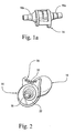
- the handle portion 16 may be omitted and the valve portion 14 may be provided with the tapered, stepped end portions 18a on both ends thereof, as shown in Fig. 1a .
- the valve portion 14 comprises a hollow valve body 20 which may be of a generally cylindrical configuration with a generally circular or elliptical cross section having end walls 22 defining a recessed area and a stop 24 extending longitudinally or axially between the end walls 22.
- the recessed outer surface 26 of the valve body 20 between the end walls 22 comprises a generally transverse or circumferential opening 28 of any suitable shape ( FIGS. 1 , 4 and 6 ) in communication with the hollow interior of the valve portion 14.
- a valve member 30 is rotatably or slidably mounted in any suitable manner on the outer surface 26 of the valve body 20 between the end walls 22 and is movable between the open position shown in FIGS. 1-6 , wherein the opening 28 is uncovered, and a closed position (not shown) wherein it covers the opening 28.
- the valve member 30 In the open position, one edge of the valve member 30 engages one side of the stop 24 (see FIG. 5 ), and in the closed position the other edge of the valve member 30 engages the opposite side of the stop 24.
- the valve member 30 is provided with a knurled or grooved outer portion 32 that may be recessed as shown in FIGS. 2 , 3 and 5 , or not recessed as shown at 132 in FIG. 7 , to facilitate the gripping and movement thereof by the thumb or other finger of the user, while being held in one hand, to control the position of the valve member 30 relative to the opening 28.
- valve body 20a may be of any suitable cross section and may have a flat, planar outer surface 26a, as shown in Fig. 7 which may or may not be recessed.
- a transverse opening 28a is provided in the surface 26a and a valve member 30a is slidably mounted on the valve body surface 26a to open or close the opening 28a.
- the opening 28 may have a "keyhole” shape to facilitate the release of all suction when it is completely uncovered, as shown in FIGS. 1 and 6 .
- the opening 28 could be slightly oblique or off the transverse or circumferential axis, and could have any suitable shape other than the "keyhole” shape, in accordance with the principles of the present invention.
- the handle portion 16 of the valve body 12 could be omitted, as shown in FIG. 1a .
- the handle portion 16 could be of any suitable size and shape.
- the outer portion 32 of the valve member 30 may be of any suitable size and shape.
- the valve member 30 and valve body 20 may be constructed in any suitable manner to provide for controlled, incremental movement of the valve member 30 relative to the valve body 20 and retention of the valve member in a desired position.
- the recessed surface 26 of the valve body 20 may be provided with a plurality of circumferentially spaced indentations 40 on both sides of the slot 28, as shown in FIG. 6 .
- the inner surface of the valve member 30 is provided with protrusions 42 that are positioned to be snap-fitted into the indentations 40 to provide for incremental movement of the valve member and its retention in a desired position.
- FIG. 8 illustrates a second embodiment of the present invention wherein the suction regulator valve 110 of the present invention is constructed as part of a suction wand or device 150 comprising a suction catheter or tip portion 152 connected to one side of the valve 110, a hollow handle portion 154 connected to the other side of the valve 110, and a connector portion 156 connected to the outer end of the handle portion 154 for connection to a suction pump (not shown) or the like.
- the handle portion 154 may be omitted and the connector portion 156 connected directly to the valve 110.
- valve member 30 and valve body 20 may be constructed in any suitable manner to insure that they are in sealing engagement to prevent leakage through the opening 28 and loss of suction when the valve member 30 is in the closed position wherein it covers the opening 28.
- the valve member 30 could be formed of a flexible and resilient material so that it would be drawn into sealing contact with the valve body 20 by the suction through the opening 28 when in the closed position.
- the portion of the stop 24 near the valve body surface 26 could be provided with a tapered recess as shown at 25 in Figure 9 , and the portion of the valve member 30 adjacent thereto when in the closed position could be provided with a complementary tapered end 27 that would be received in the recess 25 as the valve member was being moved to the closed position to urge it inwardly into tight sealing engagement with the adjacent outer surface 26 of the valve body 20.
Abstract
Description
- The present application includes the subject matter and claims the priority of Provisional Patent Application Serial No.
60/380,304 filed on May 15, 2002 - The present invention relates generally to a regulator valve and, more particularly, to a surgical suction regulator valve that can be installed in series between a suction tube and a vacuum source.
- During the course of a surgical operation on a patient, it is often necessary to remove from the site of the operation various body fluids, including blood, which tend to collect there. During childbirth, it is often necessary to remove meconium from the newborn using an intrapartum nasopharyngel suction device. In either case, the suction probe or catheter is usually connected to a pump or other type of vacuum source by means of a flexible tube. It has been found convenient to install a relief valve between the suction probe and the pump in order to control the amount of vacuum applied to the probe. Such a suction control usually consists of a valve which can be adjusted to admit a certain flow of ambient air into the tube, thus, reducing the suction force at the probe.
- In some suction devices, the air intake of the regulating valve is controlled by the operators positioning a finger over the air-intake as disclosed in
U.S. Patent No. 5,000,175, Pue . Such a device must be continuously handled by the operator. Moreover, should the operator drop the device, the maximum rate of ambient air is admitted, thus reducing or completely interrupting the suction. - Other medical suction control devices, such as the one disclosed in
U.S. Patent No. 4,356,823, Jackson , offer only a limited range of vacuum adjustments and no way to adjustably stabilize the setting of the air-intake. - Similar suction control devices in the prior art have been difficult or inconvenient to operate while being gripped with one hand.
-
WO 9806973 -
US 5899884 discloses a suction regulator (10) having an elongated hollow body (11) with interconnected distal and proximal ports (14, 16) at opposite ends thereof, each connected to an end of a flexible conduits for connection to a vacuum source, an elongated slot (22) extending axially through a wall of said hollow body, and gate member (12) which is guided axially to the hollow body between a first position oriented spaced from the wide end of said slot so as to provide unobstructed access to the slot to thereby effect a minimum suction rate at the distal port and a second position fully obstructing access to said slot to thereby effect a maximum suction rate at the distal port. - Also, they may be subject to inadvertent adjustment when tension is applied to the suction tubing.
- A principal object of the present invention is to provide a simple, yet practical regulator valve, to be placed in series between a surgical suction catheter and a surgical suction pump or other type of vacuum source, that can be easily and accurately adjusted, and can maintain its setting unattended. It is also an object of the present invention that the suction regulator valve be operable with one hand, be so simple and inexpensive that it can be disposed of after a single use, and be made of a material that can be conveniently sterilized with gamma rays.
- These and other objects are achieved by the suction regulator valve of the present invention as claimed in
claim 1. The valve body comprises a generally transverse or circumferential opening in communication with the hollow interior thereof, and a valve member is slidably or rotatably mounted on the outer surface of the valve body for transverse or circumferential movement thereon between an open position wherein the opening is uncovered and a closed position wherein it covers the opening. The valve member may be easily and accurately manipulated by the thumb or other finger of the user while gripping the suction regulator valve with one hand. The suction regulator valve may be a separate member, may have a handle portion or may be assembled as part of a suction wand or other suction device. -
-
FIG. 1 is a perspective view of one side portion of the suction regulator valve of the present invention; -
FIG. 1a is a perspective view of the suction regulator valve ofFIG. 1 without the handle portion; -
FIG. 2 is a perspective view of one end of the suction regulator valve; -
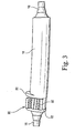
FIG. 3 is a perspective view of another side portion of the suction regulator valve; -
FIG. 4 is a perspective view of a further side portion of the suction regulator valve; -
FIG. 5 is a perspective view of a still further side portion of the suction regulator valve; -
FIG. 6 is an enlarged perspective view of a portion of the suction regulator valve shown inFIG. 4 ; -
FIG. 7 is a perspective view of a further embodiment of the suction regulator valve having a valve body with a generally flat outer surface; -
FIG. 8 is a perspective view of a second embodiment of the present invention wherein the suction regulator valve is constructed as an integral part of a suction wand or device; and -
FIG. 9 is an enlarged perspective view similar toFIG. 6 showing a still further embodiment of the suction regulator. - Referring to
FIG. 1 , theregulator valve 10 of the present invention preferably is formed of a medically suitable thermal plastic or other suitable material, and generally comprises ahollow body 12 having avalve portion 14 and ahollow handle portion 16 with tapered, steppedend portions 18 or the like that are adapted to be attached to suction tubing (not shown). Thehandle portion 16 may be slightly curved to enable it to fit easily in the palm of a physician or other user. Alternatively, thehandle portion 16 may be omitted and thevalve portion 14 may be provided with the tapered, steppedend portions 18a on both ends thereof, as shown inFig. 1a . - As shown in
FIGS 1-5 , thevalve portion 14 comprises ahollow valve body 20 which may be of a generally cylindrical configuration with a generally circular or elliptical cross section havingend walls 22 defining a recessed area and astop 24 extending longitudinally or axially between theend walls 22. The recessedouter surface 26 of thevalve body 20 between theend walls 22 comprises a generally transverse orcircumferential opening 28 of any suitable shape (FIGS. 1 ,4 and6 ) in communication with the hollow interior of thevalve portion 14. - A
valve member 30 is rotatably or slidably mounted in any suitable manner on theouter surface 26 of thevalve body 20 between theend walls 22 and is movable between the open position shown inFIGS. 1-6 , wherein theopening 28 is uncovered, and a closed position (not shown) wherein it covers theopening 28. In the open position, one edge of thevalve member 30 engages one side of the stop 24 (seeFIG. 5 ), and in the closed position the other edge of thevalve member 30 engages the opposite side of thestop 24. Preferably, thevalve member 30 is provided with a knurled or groovedouter portion 32 that may be recessed as shown inFIGS. 2 ,3 and5 , or not recessed as shown at 132 inFIG. 7 , to facilitate the gripping and movement thereof by the thumb or other finger of the user, while being held in one hand, to control the position of thevalve member 30 relative to theopening 28. - Within the scope of the present invention, the
valve body 20a may be of any suitable cross section and may have a flat, planarouter surface 26a, as shown inFig. 7 which may or may not be recessed. Atransverse opening 28a is provided in thesurface 26a and avalve member 30a is slidably mounted on thevalve body surface 26a to open or close the opening 28a. - The opening 28 may have a "keyhole" shape to facilitate the release of all suction when it is completely uncovered, as shown in
FIGS. 1 and6 . Also, theopening 28 could be slightly oblique or off the transverse or circumferential axis, and could have any suitable shape other than the "keyhole" shape, in accordance with the principles of the present invention. - For applications where space is limited, the
handle portion 16 of thevalve body 12 could be omitted, as shown inFIG. 1a . Also, thehandle portion 16 could be of any suitable size and shape. Similarly, theouter portion 32 of thevalve member 30 may be of any suitable size and shape. - The
valve member 30 andvalve body 20 may be constructed in any suitable manner to provide for controlled, incremental movement of thevalve member 30 relative to thevalve body 20 and retention of the valve member in a desired position. As an illustrative example, therecessed surface 26 of the valve body 20may be provided with a plurality of circumferentially spacedindentations 40 on both sides of theslot 28, as shown inFIG. 6 . The inner surface of thevalve member 30 is provided withprotrusions 42 that are positioned to be snap-fitted into theindentations 40 to provide for incremental movement of the valve member and its retention in a desired position. -
FIG. 8 illustrates a second embodiment of the present invention wherein thesuction regulator valve 110 of the present invention is constructed as part of a suction wand ordevice 150 comprising a suction catheter ortip portion 152 connected to one side of thevalve 110, ahollow handle portion 154 connected to the other side of thevalve 110, and a connector portion 156 connected to the outer end of thehandle portion 154 for connection to a suction pump (not shown) or the like. Thehandle portion 154 may be omitted and the connector portion 156 connected directly to thevalve 110. - The
valve member 30 andvalve body 20 may be constructed in any suitable manner to insure that they are in sealing engagement to prevent leakage through theopening 28 and loss of suction when thevalve member 30 is in the closed position wherein it covers theopening 28. For example, thevalve member 30 could be formed of a flexible and resilient material so that it would be drawn into sealing contact with thevalve body 20 by the suction through theopening 28 when in the closed position. As an alternative, the portion of thestop 24 near thevalve body surface 26 could be provided with a tapered recess as shown at 25 inFigure 9 , and the portion of thevalve member 30 adjacent thereto when in the closed position could be provided with a complementarytapered end 27 that would be received in therecess 25 as the valve member was being moved to the closed position to urge it inwardly into tight sealing engagement with the adjacentouter surface 26 of thevalve body 20. - Some of the advantages of the present suction regulator valve are as follows:
- 1. The generally transverse or circumferential orientation of the
opening 28 allows thevalve portion 14 to be of a small size or width to facilitate its incorporation in other surgical tools, such as a suction wand or the like; - 2. The transverse or circumferential movement of the
valve member 30, rather than axial or longitudinal movement thereof, helps to prevent its inadvertent movement if there is a pull on the suction tubing connected to it; - 3. The valve member can be easily operated by either hand of the user and can be connected to suction tubing in any direction;
- 4. The
valve member 30 can be easily moved by the thumb or other finger of a user, while the suction valve is held in one hand, to cover all, a portion of or none of theopening 28; and - 5. The valve is simple in construction, easy and inexpensive to manufacture, reliable in operation and easy to install in a suction device.
- While the invention has been described in connection with what are presently considered to be the most practical and preferred embodiments, it is to be understood that the invention is not to be limited to the disclosed embodiments, but on the contrary, is intended to cover various modifications and equivalent arrangements included within the scope of the appended claims.
Claims (15)
- A surgical suction regulator valve (10) being of a size and constructed to be installed between a surgical suction pump and a surgical suction catheter used for the removal of body fluids during a medical procedure, said valve comprising:a hollow valve body (12) having a longitudinal axis, said valve body (12) having an outer surface with an elongated opening (28) therethrough
characterized in that:said elongated opening (28) extends circumferentially to said longitudinal axis, anda valve member (30) is slidably mounted on said valve body (12) for circumferential movement on said outer surface thereof adjacent to said elongated opening (28), said valve member (30) being movable between an open position wherein said opening (28) is uncovered and a closed position wherein said valve member (30) covers and closes said opening (28). - The valve of claim 1 wherein said valve member (30) is positioned for engagement by the thumb or other finger of a user to enable the movement of said valve member (30) to cover or uncovee all or a portion of said opening (28).
- The valve of claim 1 wherein said valve body (12) comprises a hollow handle portion (16) connected thereto and positioned to enable the gripping thereof by one hand of a user and the engagement of said valve member (30) by the thumb or other finger of the one hand of the user.
- The valve of claim 3 wherein said handle portion (16) is connected to one end of said valve body (12), and further comprising a surgical suction tube (152) attached to the other end of said valve body.
- The valve of claim 1 wherein said valve body (12) comprises a stop (24) for limiting the opening and closing movement of said valve member (30).
- The valve of claim 5 wherein said valve body (12) comprises axially spaced end walls (22), and said stop (24) comprises a wall extending generally longitudinally between said end wails.
- The valve of claim 6 wherein said valve body (12) is of generally cylindrical configuration, said valve member (30) is of generally annular shape, and said opening (28) is a generally circumferential slot.
- The valve of claim 7 wherein said end walls (22) of said valve body (12) are generally elliptical in shape.
- The suction regulator valve of claim 6 wherein said outer surface of said valve body (12) is recessed between said end walls (22), and said valve member (30) is slidable on said outer surface between said end walls (22).
- The valve of claim 9 wherein said valve member (30) is in slidable engagement with said end walls (22).
- The valve of claim 1 wherein said valve body (12) is of generally cylindrical configuration, said valve member (30) is of generally annular shape, and said opening (28) is generally circumferential slot.
- The suction regulator valve of claim 1 wherein said valve member (30) is in sealing engagement with the adjacent outer surface of said valve body (12) when in said closed position.
- The suction regulator valve of claim 12 wherein said valve member (30) is formed of a flexible and resilient material to enable it to be drawn into sealing engagement with the adjacent outer surface of said valve body (12) when in said closed position.
- The suction device of claim 1 wherein said valve body (12) comprises a stop (24) for limiting the opening and closing movement of said valve member (30), and said stop (24) has a recess (25) near said outer surface of said valve body (12) which is positioned to receive the adjacent end portion of said valve member (30) as it is being moved to said closed position to urge it into sealing engagement with the adjacent outer surface of said valve body (12).
- The suction regulator valve of claim 14 wherein said recess (25) in said stop (24) and said adjacent end portion of said valve body (12) are tapered in a complementary manner.
Applications Claiming Priority (5)
| Application Number | Priority Date | Filing Date | Title |
|---|---|---|---|
| US38030402P | 2002-05-15 | 2002-05-15 | |
| US380304P | 2002-05-15 | ||
| US10/287,546 US6875198B2 (en) | 2002-05-15 | 2002-11-05 | Surgical suction regulator valve |
| US287546 | 2002-11-05 | ||
| PCT/US2003/009434 WO2003097129A1 (en) | 2002-05-15 | 2003-03-27 | Surgical suction regulator valve |
Publications (3)
| Publication Number | Publication Date |
|---|---|
| EP1553994A1 EP1553994A1 (en) | 2005-07-20 |
| EP1553994A4 EP1553994A4 (en) | 2010-03-31 |
| EP1553994B1 true EP1553994B1 (en) | 2012-02-08 |
Family
ID=29423253
Family Applications (1)
| Application Number | Title | Priority Date | Filing Date |
|---|---|---|---|
| EP03718080A Expired - Lifetime EP1553994B1 (en) | 2002-05-15 | 2003-03-27 | Surgical suction regulator valve |
Country Status (10)
| Country | Link |
|---|---|
| US (2) | US6875198B2 (en) |
| EP (1) | EP1553994B1 (en) |
| JP (1) | JP4373911B2 (en) |
| CN (1) | CN100589848C (en) |
| AT (1) | ATE544478T1 (en) |
| AU (1) | AU2003222094B2 (en) |
| CA (1) | CA2485742C (en) |
| ES (1) | ES2382151T3 (en) |
| HK (1) | HK1078038A1 (en) |
| WO (1) | WO2003097129A1 (en) |
Cited By (1)
| Publication number | Priority date | Publication date | Assignee | Title |
|---|---|---|---|---|
| DE102016014241A1 (en) | 2016-11-30 | 2018-05-30 | Karl Storz Se & Co. Kg | Medical suction regulator |
Families Citing this family (27)
| Publication number | Priority date | Publication date | Assignee | Title |
|---|---|---|---|---|
| EP1756109B1 (en) * | 2004-05-03 | 2016-07-13 | Janssen Pharmaceutica NV | Novel indole derivatives as selective androgen receptor modulators (sarms) |
| US7588533B2 (en) * | 2004-11-26 | 2009-09-15 | Joanne Drysdale | Sexual therapy device |
| US20070287933A1 (en) * | 2006-06-08 | 2007-12-13 | Chris Phan | Tissue debulking device and method of using the same |
| US8414550B2 (en) | 2006-09-29 | 2013-04-09 | Lexion Medical, Llc | System and method to vent gas from a body cavity |
| US7913693B2 (en) * | 2006-11-10 | 2011-03-29 | Nellcor Puritan Bennett Llc | Method and apparatus for preventing occlusion of a tracheal tube suction lumen |
| US8585646B2 (en) | 2008-03-03 | 2013-11-19 | Lexion Medical, Llc | System and method to vent gas from a body cavity |
| US10271716B2 (en) | 2008-06-27 | 2019-04-30 | C.R. Bard, Inc. | Endoscopic vacuum controller |
| CA2964741C (en) | 2009-03-09 | 2019-10-29 | Thermedx, Llc | Surgical fluid management system |
| US9474848B2 (en) | 2009-03-09 | 2016-10-25 | Thermedx, Llc | Fluid management system |
| US9775664B2 (en) * | 2009-09-22 | 2017-10-03 | Mederi Therapeutics, Inc. | Systems and methods for treating tissue with radiofrequency energy |
| WO2012012348A1 (en) * | 2010-07-17 | 2012-01-26 | The New York And Presbyterian Hospital | Methods and systems for minimally invasive endoscopic surgeries |
| DE102011052196B4 (en) * | 2011-07-27 | 2017-06-08 | MAQUET GmbH | Device for aspirating liquids and / or particles from body orifices |
| USD668410S1 (en) | 2011-11-11 | 2012-10-02 | Telebrands Corp. | Vacuum cleaner attachment adapter |
| US9775672B2 (en) * | 2012-08-31 | 2017-10-03 | Nico Corporation | Bi-polar surgical instrument |
| US10383680B2 (en) * | 2012-08-31 | 2019-08-20 | Nico Corporation | Bi-polar surgical instrument |
| CN103285506B (en) * | 2013-05-13 | 2016-04-13 | 常熟市精亮微医疗器械科技有限公司 | Novel clamp type drain valve |
| US9770541B2 (en) | 2014-05-15 | 2017-09-26 | Thermedx, Llc | Fluid management system with pass-through fluid volume measurement |
| EP3166655B1 (en) * | 2014-07-07 | 2019-07-03 | Promev S.r.l. | Pressure reducer for surgical aspiration systems |
| EP3200706A4 (en) * | 2014-10-02 | 2018-06-20 | George Crawford | Suction adapter device |
| US10166036B2 (en) * | 2014-10-16 | 2019-01-01 | Gyrus Acmi, Inc. | Variable suction control |
| US9872943B1 (en) | 2015-03-30 | 2018-01-23 | The United States Of America As Represented By The Secretary Of The Air Force | Pistol grip suction device |
| DE102017124927A1 (en) | 2017-10-25 | 2019-04-25 | Irasun Gmbh | Vacuum assisted venous drainage system (VAVD) |
| US11191885B2 (en) * | 2018-12-06 | 2021-12-07 | Joshua C. Arnone | Flow control system |
| US20220226558A1 (en) * | 2019-02-13 | 2022-07-21 | Stryker European Operations Limited | Bone Material Harvesting Device |
| US20210138163A1 (en) | 2019-11-08 | 2021-05-13 | Thermedx Llc | Fluid Management Systems and Methods |
| EP3936168A1 (en) * | 2020-07-10 | 2022-01-12 | Bo Karlsmose | A suction control handle comprising a cover element |
| USD978346S1 (en) | 2022-08-12 | 2023-02-14 | Br Surgical, Llc | Separated finger pad for a surgical suction instrument |
Family Cites Families (31)
| Publication number | Priority date | Publication date | Assignee | Title |
|---|---|---|---|---|
| US3395705A (en) | 1965-10-18 | 1968-08-06 | American Hospital Supply Corp | Medical suction apparatus |
| US3625221A (en) * | 1969-07-29 | 1971-12-07 | Sherwood Medical Ind Inc | Flap-trol suction catheter |
| US3834388A (en) | 1973-01-29 | 1974-09-10 | Cenco Medical Health Supply Co | Suction control arrangement for a suction catheter |
| US3863635A (en) * | 1974-02-22 | 1975-02-04 | Den Tal Ez Mfg Co | Vacuum handpiece including integral vacuum valve |
| US5000175A (en) | 1979-08-08 | 1991-03-19 | Pue Alexander F | Meconium aspiration device |
| US4356823A (en) | 1980-05-30 | 1982-11-02 | Jackson Richard R | Suction control |
| US4445517A (en) * | 1981-09-28 | 1984-05-01 | Feild James Rodney | Suction dissector |
| JPS58133229A (en) * | 1982-02-02 | 1983-08-08 | オリンパス光学工業株式会社 | Suction change-over valve of endoscope |
| US4662871A (en) | 1984-09-18 | 1987-05-05 | Stephen Rafelson | Disposable suction catheter and system for providing multiple suctioning capabilities during medical procedures or the like |
| US4964849A (en) * | 1986-01-06 | 1990-10-23 | Francis Robicsek | Two-way suction apparatus for surgical procedures |
| US4784649A (en) * | 1987-03-20 | 1988-11-15 | The Cooper Companies, Inc. | Surgical aspirator cannula |
| US5127694A (en) * | 1990-03-03 | 1992-07-07 | The Triangle Tool Group | Vacuum manipulator |
| US4878900A (en) | 1988-07-27 | 1989-11-07 | Sundt Thoralf M | Surgical probe and suction device |
| US5203769A (en) * | 1989-11-06 | 1993-04-20 | Mectra Labs, Inc. | Medical device valving mechanism |
| US4961245A (en) * | 1990-02-05 | 1990-10-09 | Ryobi Motor Products Corp. | Suction controlling arrangement in a canister vacuum cleaner |
| FR2676365B1 (en) * | 1991-05-13 | 1993-08-20 | Gerard Adhoute | SUCTION DEVICE FOR PEROPERATIVE SELF-TRANSFUSION. |
| US5169192A (en) * | 1991-06-28 | 1992-12-08 | H-Square Corporation | Electronic article pickup tool |
| US5335655A (en) * | 1992-09-10 | 1994-08-09 | Sherwood Medical Company | Suction control valve |
| US5320328A (en) | 1993-08-09 | 1994-06-14 | Sherwood Medical Company | Suction control valve with vacuum breaker |
| US5676136A (en) * | 1993-12-07 | 1997-10-14 | Russo; Ronald D. | Protective suction control catheter with valve |
| US5531712A (en) | 1994-09-30 | 1996-07-02 | Malcolm; Roger J. | Surgical suction regulator valve |
| US5730727A (en) * | 1995-06-12 | 1998-03-24 | Russo; Ronald D. | Thumb conformable suction control regulator |
| US5704090A (en) * | 1995-09-08 | 1998-01-06 | Shop Vac Corporation | Bleed for a vacuum cleaner |
| US5890516A (en) * | 1996-08-12 | 1999-04-06 | Talamonti; Anthony R. | Stomach suction pump connector valve |
| US5836909A (en) * | 1996-09-13 | 1998-11-17 | Cosmescu; Ioan | Automatic fluid control system for use in open and laparoscopic laser surgery and electrosurgery and method therefor |
| USD412984S (en) | 1997-01-17 | 1999-08-17 | Stryker Corporation | Surgical suction regulator |
| US5899884A (en) | 1997-01-17 | 1999-05-04 | Stryker Corporation | Suction regulator |
| US5919174A (en) | 1997-02-03 | 1999-07-06 | Sorenson Critical Care, Inc. | Suction valve assembly |
| US5993410A (en) * | 1997-07-08 | 1999-11-30 | Cabot Technology Corporation | Adjustable probe |
| US6364853B1 (en) * | 2000-09-11 | 2002-04-02 | Scion International, Inc. | Irrigation and suction valve and method therefor |
| US6343823B1 (en) * | 2000-10-23 | 2002-02-05 | William G. Busby | Vacuum pickup tool |
-
2002
- 2002-11-05 US US10/287,546 patent/US6875198B2/en not_active Expired - Fee Related
-
2003
- 2003-03-27 JP JP2004505124A patent/JP4373911B2/en not_active Expired - Fee Related
- 2003-03-27 CN CN03810874A patent/CN100589848C/en not_active Expired - Fee Related
- 2003-03-27 WO PCT/US2003/009434 patent/WO2003097129A1/en active Application Filing
- 2003-03-27 AT AT03718080T patent/ATE544478T1/en active
- 2003-03-27 EP EP03718080A patent/EP1553994B1/en not_active Expired - Lifetime
- 2003-03-27 ES ES03718080T patent/ES2382151T3/en not_active Expired - Lifetime
- 2003-03-27 AU AU2003222094A patent/AU2003222094B2/en not_active Ceased
- 2003-03-27 CA CA2485742A patent/CA2485742C/en not_active Expired - Fee Related
-
2005
- 2005-02-11 US US11/055,104 patent/US7611490B2/en active Active - Reinstated
-
2006
- 2006-01-19 HK HK06100864.7A patent/HK1078038A1/en not_active IP Right Cessation
Cited By (1)
| Publication number | Priority date | Publication date | Assignee | Title |
|---|---|---|---|---|
| DE102016014241A1 (en) | 2016-11-30 | 2018-05-30 | Karl Storz Se & Co. Kg | Medical suction regulator |
Also Published As
| Publication number | Publication date |
|---|---|
| JP4373911B2 (en) | 2009-11-25 |
| CN100589848C (en) | 2010-02-17 |
| CA2485742A1 (en) | 2003-11-27 |
| US6875198B2 (en) | 2005-04-05 |
| CN1652830A (en) | 2005-08-10 |
| EP1553994A1 (en) | 2005-07-20 |
| HK1078038A1 (en) | 2006-03-03 |
| WO2003097129A1 (en) | 2003-11-27 |
| US7611490B2 (en) | 2009-11-03 |
| CA2485742C (en) | 2010-11-02 |
| AU2003222094B2 (en) | 2008-01-31 |
| JP2005525197A (en) | 2005-08-25 |
| AU2003222094A1 (en) | 2003-12-02 |
| EP1553994A4 (en) | 2010-03-31 |
| ES2382151T3 (en) | 2012-06-05 |
| US20050148937A1 (en) | 2005-07-07 |
| ATE544478T1 (en) | 2012-02-15 |
| US20030216690A1 (en) | 2003-11-20 |
Similar Documents
| Publication | Publication Date | Title |
|---|---|---|
| EP1553994B1 (en) | Surgical suction regulator valve | |
| US11759616B2 (en) | Connector with valve for negative pressure wound therapy system | |
| US6390975B1 (en) | Apparatus and methods for performing otoscopic procedures | |
| US5230704A (en) | Suction/irrigation instrument having reusable handle with disposable fluid path | |
| EP1991288B1 (en) | Endoscopic suction device | |
| EP0779823B1 (en) | Suction stylet for use with an endotracheal tube | |
| US5520651A (en) | Self releasing suction and irrigation apparatus and method of attachment | |
| US5899884A (en) | Suction regulator | |
| EP0600895A1 (en) | Trocar with multiple converters and detachable obturator | |
| WO2006119512A2 (en) | Surgical tool and insertion device for tube placement | |
| US20060212056A1 (en) | Surgical instrument | |
| JP2012501711A (en) | Surgical manipulator | |
| JPH01502721A (en) | surgical suction cannula | |
| US20200054852A1 (en) | Tracheal intubation device for delivery of apneic oxygenation and suction | |
| US20060167469A1 (en) | Suction controlled extraction device | |
| KR100978339B1 (en) | Surgical suction regulator valve | |
| US7722627B2 (en) | Surgical ligation instrument | |
| CN215780300U (en) | Improved negative pressure drainage tube clamping and fixing device | |
| JP2014530738A (en) | Instrument access device | |
| US20240139458A1 (en) | Tracheal intubation device for delivery of apneic oxygenation and suction | |
| JPH0539709Y2 (en) | ||
| JP4475775B2 (en) | Endoscope treatment tool insertion part | |
| JPH06197952A (en) | Suction and irrigation device for surgical treatment |
Legal Events
| Date | Code | Title | Description |
|---|---|---|---|
| PUAI | Public reference made under article 153(3) epc to a published international application that has entered the european phase |
Free format text: ORIGINAL CODE: 0009012 |
|
| 17P | Request for examination filed |
Effective date: 20041216 |
|
| AK | Designated contracting states |
Kind code of ref document: A1 Designated state(s): AT BE BG CH CY CZ DE DK EE ES FI FR GB GR HU IE IT LI LU MC NL PT RO SE SI SK TR |
|
| AX | Request for extension of the european patent |
Extension state: AL LT LV MK |
|
| R17P | Request for examination filed (corrected) |
Effective date: 20041206 |
|
| DAX | Request for extension of the european patent (deleted) | ||
| REG | Reference to a national code |
Ref country code: HK Ref legal event code: DE Ref document number: 1078038 Country of ref document: HK |
|
| A4 | Supplementary search report drawn up and despatched |
Effective date: 20100225 |
|
| 17Q | First examination report despatched |
Effective date: 20110120 |
|
| RIC1 | Information provided on ipc code assigned before grant |
Ipc: A61M 1/00 20060101AFI20110531BHEP |
|
| GRAP | Despatch of communication of intention to grant a patent |
Free format text: ORIGINAL CODE: EPIDOSNIGR1 |
|
| GRAS | Grant fee paid |
Free format text: ORIGINAL CODE: EPIDOSNIGR3 |
|
| GRAA | (expected) grant |
Free format text: ORIGINAL CODE: 0009210 |
|
| AK | Designated contracting states |
Kind code of ref document: B1 Designated state(s): AT BE BG CH CY CZ DE DK EE ES FI FR GB GR HU IE IT LI LU MC NL PT RO SE SI SK TR |
|
| REG | Reference to a national code |
Ref country code: GB Ref legal event code: FG4D |
|
| REG | Reference to a national code |
Ref country code: AT Ref legal event code: REF Ref document number: 544478 Country of ref document: AT Kind code of ref document: T Effective date: 20120215 Ref country code: CH Ref legal event code: EP |
|
| REG | Reference to a national code |
Ref country code: DE Ref legal event code: R096 Ref document number: 60339946 Country of ref document: DE Effective date: 20120405 |
|
| REG | Reference to a national code |
Ref country code: SE Ref legal event code: TRGR |
|
| REG | Reference to a national code |
Ref country code: CH Ref legal event code: NV Representative=s name: BOHEST AG |
|
| REG | Reference to a national code |
Ref country code: ES Ref legal event code: FG2A Ref document number: 2382151 Country of ref document: ES Kind code of ref document: T3 Effective date: 20120605 |
|
| REG | Reference to a national code |
Ref country code: NL Ref legal event code: VDEP Effective date: 20120208 |
|
| PG25 | Lapsed in a contracting state [announced via postgrant information from national office to epo] |
Ref country code: NL Free format text: LAPSE BECAUSE OF FAILURE TO SUBMIT A TRANSLATION OF THE DESCRIPTION OR TO PAY THE FEE WITHIN THE PRESCRIBED TIME-LIMIT Effective date: 20120208 |
|
| PGFP | Annual fee paid to national office [announced via postgrant information from national office to epo] |
Ref country code: CH Payment date: 20120529 Year of fee payment: 10 Ref country code: DE Payment date: 20120509 Year of fee payment: 10 |
|
| PG25 | Lapsed in a contracting state [announced via postgrant information from national office to epo] |
Ref country code: FI Free format text: LAPSE BECAUSE OF FAILURE TO SUBMIT A TRANSLATION OF THE DESCRIPTION OR TO PAY THE FEE WITHIN THE PRESCRIBED TIME-LIMIT Effective date: 20120208 Ref country code: GR Free format text: LAPSE BECAUSE OF FAILURE TO SUBMIT A TRANSLATION OF THE DESCRIPTION OR TO PAY THE FEE WITHIN THE PRESCRIBED TIME-LIMIT Effective date: 20120509 Ref country code: PT Free format text: LAPSE BECAUSE OF FAILURE TO SUBMIT A TRANSLATION OF THE DESCRIPTION OR TO PAY THE FEE WITHIN THE PRESCRIBED TIME-LIMIT Effective date: 20120608 Ref country code: BE Free format text: LAPSE BECAUSE OF FAILURE TO SUBMIT A TRANSLATION OF THE DESCRIPTION OR TO PAY THE FEE WITHIN THE PRESCRIBED TIME-LIMIT Effective date: 20120208 |
|
| PGFP | Annual fee paid to national office [announced via postgrant information from national office to epo] |
Ref country code: GB Payment date: 20120521 Year of fee payment: 10 Ref country code: SE Payment date: 20120504 Year of fee payment: 10 Ref country code: FR Payment date: 20120618 Year of fee payment: 10 |
|
| REG | Reference to a national code |
Ref country code: HK Ref legal event code: GR Ref document number: 1078038 Country of ref document: HK |
|
| REG | Reference to a national code |
Ref country code: AT Ref legal event code: MK05 Ref document number: 544478 Country of ref document: AT Kind code of ref document: T Effective date: 20120208 |
|
| PG25 | Lapsed in a contracting state [announced via postgrant information from national office to epo] |
Ref country code: CY Free format text: LAPSE BECAUSE OF FAILURE TO SUBMIT A TRANSLATION OF THE DESCRIPTION OR TO PAY THE FEE WITHIN THE PRESCRIBED TIME-LIMIT Effective date: 20120208 |
|
| PGFP | Annual fee paid to national office [announced via postgrant information from national office to epo] |
Ref country code: IT Payment date: 20120525 Year of fee payment: 10 |
|
| PG25 | Lapsed in a contracting state [announced via postgrant information from national office to epo] |
Ref country code: EE Free format text: LAPSE BECAUSE OF FAILURE TO SUBMIT A TRANSLATION OF THE DESCRIPTION OR TO PAY THE FEE WITHIN THE PRESCRIBED TIME-LIMIT Effective date: 20120208 Ref country code: DK Free format text: LAPSE BECAUSE OF FAILURE TO SUBMIT A TRANSLATION OF THE DESCRIPTION OR TO PAY THE FEE WITHIN THE PRESCRIBED TIME-LIMIT Effective date: 20120208 Ref country code: RO Free format text: LAPSE BECAUSE OF FAILURE TO SUBMIT A TRANSLATION OF THE DESCRIPTION OR TO PAY THE FEE WITHIN THE PRESCRIBED TIME-LIMIT Effective date: 20120208 Ref country code: CZ Free format text: LAPSE BECAUSE OF FAILURE TO SUBMIT A TRANSLATION OF THE DESCRIPTION OR TO PAY THE FEE WITHIN THE PRESCRIBED TIME-LIMIT Effective date: 20120208 Ref country code: SI Free format text: LAPSE BECAUSE OF FAILURE TO SUBMIT A TRANSLATION OF THE DESCRIPTION OR TO PAY THE FEE WITHIN THE PRESCRIBED TIME-LIMIT Effective date: 20120208 Ref country code: MC Free format text: LAPSE BECAUSE OF NON-PAYMENT OF DUE FEES Effective date: 20120331 |
|
| PG25 | Lapsed in a contracting state [announced via postgrant information from national office to epo] |
Ref country code: SK Free format text: LAPSE BECAUSE OF FAILURE TO SUBMIT A TRANSLATION OF THE DESCRIPTION OR TO PAY THE FEE WITHIN THE PRESCRIBED TIME-LIMIT Effective date: 20120208 |
|
| PLBE | No opposition filed within time limit |
Free format text: ORIGINAL CODE: 0009261 |
|
| STAA | Information on the status of an ep patent application or granted ep patent |
Free format text: STATUS: NO OPPOSITION FILED WITHIN TIME LIMIT |
|
| PGFP | Annual fee paid to national office [announced via postgrant information from national office to epo] |
Ref country code: ES Payment date: 20120508 Year of fee payment: 10 |
|
| REG | Reference to a national code |
Ref country code: IE Ref legal event code: MM4A |
|
| 26N | No opposition filed |
Effective date: 20121109 |
|
| PG25 | Lapsed in a contracting state [announced via postgrant information from national office to epo] |
Ref country code: IE Free format text: LAPSE BECAUSE OF NON-PAYMENT OF DUE FEES Effective date: 20120327 Ref country code: AT Free format text: LAPSE BECAUSE OF FAILURE TO SUBMIT A TRANSLATION OF THE DESCRIPTION OR TO PAY THE FEE WITHIN THE PRESCRIBED TIME-LIMIT Effective date: 20120208 |
|
| REG | Reference to a national code |
Ref country code: DE Ref legal event code: R097 Ref document number: 60339946 Country of ref document: DE Effective date: 20121109 |
|
| PG25 | Lapsed in a contracting state [announced via postgrant information from national office to epo] |
Ref country code: BG Free format text: LAPSE BECAUSE OF FAILURE TO SUBMIT A TRANSLATION OF THE DESCRIPTION OR TO PAY THE FEE WITHIN THE PRESCRIBED TIME-LIMIT Effective date: 20120508 |
|
| REG | Reference to a national code |
Ref country code: SE Ref legal event code: EUG |
|
| PG25 | Lapsed in a contracting state [announced via postgrant information from national office to epo] |
Ref country code: SE Free format text: LAPSE BECAUSE OF NON-PAYMENT OF DUE FEES Effective date: 20130328 |
|
| REG | Reference to a national code |
Ref country code: CH Ref legal event code: PL |
|
| GBPC | Gb: european patent ceased through non-payment of renewal fee |
Effective date: 20130327 |
|
| REG | Reference to a national code |
Ref country code: FR Ref legal event code: ST Effective date: 20131129 |
|
| REG | Reference to a national code |
Ref country code: DE Ref legal event code: R119 Ref document number: 60339946 Country of ref document: DE Effective date: 20131001 |
|
| PG25 | Lapsed in a contracting state [announced via postgrant information from national office to epo] |
Ref country code: GB Free format text: LAPSE BECAUSE OF NON-PAYMENT OF DUE FEES Effective date: 20130327 Ref country code: FR Free format text: LAPSE BECAUSE OF NON-PAYMENT OF DUE FEES Effective date: 20130402 Ref country code: LI Free format text: LAPSE BECAUSE OF NON-PAYMENT OF DUE FEES Effective date: 20130331 Ref country code: CH Free format text: LAPSE BECAUSE OF NON-PAYMENT OF DUE FEES Effective date: 20130331 Ref country code: DE Free format text: LAPSE BECAUSE OF NON-PAYMENT OF DUE FEES Effective date: 20131001 |
|
| PG25 | Lapsed in a contracting state [announced via postgrant information from national office to epo] |
Ref country code: IT Free format text: LAPSE BECAUSE OF NON-PAYMENT OF DUE FEES Effective date: 20130327 |
|
| PG25 | Lapsed in a contracting state [announced via postgrant information from national office to epo] |
Ref country code: TR Free format text: LAPSE BECAUSE OF FAILURE TO SUBMIT A TRANSLATION OF THE DESCRIPTION OR TO PAY THE FEE WITHIN THE PRESCRIBED TIME-LIMIT Effective date: 20120208 |
|
| PG25 | Lapsed in a contracting state [announced via postgrant information from national office to epo] |
Ref country code: LU Free format text: LAPSE BECAUSE OF NON-PAYMENT OF DUE FEES Effective date: 20120327 |
|
| REG | Reference to a national code |
Ref country code: ES Ref legal event code: FD2A Effective date: 20140611 |
|
| PG25 | Lapsed in a contracting state [announced via postgrant information from national office to epo] |
Ref country code: HU Free format text: LAPSE BECAUSE OF FAILURE TO SUBMIT A TRANSLATION OF THE DESCRIPTION OR TO PAY THE FEE WITHIN THE PRESCRIBED TIME-LIMIT Effective date: 20030327 |
|
| PG25 | Lapsed in a contracting state [announced via postgrant information from national office to epo] |
Ref country code: ES Free format text: LAPSE BECAUSE OF NON-PAYMENT OF DUE FEES Effective date: 20130328 |