EP1555334A1 - Vaporization equipment for material sublimation - Google Patents
Vaporization equipment for material sublimation Download PDFInfo
- Publication number
- EP1555334A1 EP1555334A1 EP04004928A EP04004928A EP1555334A1 EP 1555334 A1 EP1555334 A1 EP 1555334A1 EP 04004928 A EP04004928 A EP 04004928A EP 04004928 A EP04004928 A EP 04004928A EP 1555334 A1 EP1555334 A1 EP 1555334A1
- Authority
- EP
- European Patent Office
- Prior art keywords
- evaporation device
- tub
- trough
- heating
- housing
- Prior art date
- Legal status (The legal status is an assumption and is not a legal conclusion. Google has not performed a legal analysis and makes no representation as to the accuracy of the status listed.)
- Granted
Links
- 239000000463 material Substances 0.000 title claims abstract description 17
- 230000008016 vaporization Effects 0.000 title abstract 2
- 238000009834 vaporization Methods 0.000 title abstract 2
- 230000008022 sublimation Effects 0.000 title 1
- 238000000859 sublimation Methods 0.000 title 1
- 238000010438 heat treatment Methods 0.000 claims abstract description 27
- 239000000919 ceramic Substances 0.000 claims abstract description 3
- 238000001704 evaporation Methods 0.000 claims description 26
- 230000008020 evaporation Effects 0.000 claims description 26
- 238000001771 vacuum deposition Methods 0.000 claims description 3
- 238000000576 coating method Methods 0.000 description 7
- 239000011248 coating agent Substances 0.000 description 6
- 239000011888 foil Substances 0.000 description 3
- 239000005083 Zinc sulfide Substances 0.000 description 2
- 238000004140 cleaning Methods 0.000 description 2
- 238000010025 steaming Methods 0.000 description 2
- 229910052984 zinc sulfide Inorganic materials 0.000 description 2
- DRDVZXDWVBGGMH-UHFFFAOYSA-N zinc;sulfide Chemical compound [S-2].[Zn+2] DRDVZXDWVBGGMH-UHFFFAOYSA-N 0.000 description 2
- OKTJSMMVPCPJKN-UHFFFAOYSA-N Carbon Chemical compound [C] OKTJSMMVPCPJKN-UHFFFAOYSA-N 0.000 description 1
- ZOKXTWBITQBERF-UHFFFAOYSA-N Molybdenum Chemical compound [Mo] ZOKXTWBITQBERF-UHFFFAOYSA-N 0.000 description 1
- 239000013590 bulk material Substances 0.000 description 1
- 238000005352 clarification Methods 0.000 description 1
- 239000004020 conductor Substances 0.000 description 1
- 238000010292 electrical insulation Methods 0.000 description 1
- 230000005611 electricity Effects 0.000 description 1
- 239000008187 granular material Substances 0.000 description 1
- 229910002804 graphite Inorganic materials 0.000 description 1
- 239000010439 graphite Substances 0.000 description 1
- 238000009434 installation Methods 0.000 description 1
- 229910052750 molybdenum Inorganic materials 0.000 description 1
- 239000011733 molybdenum Substances 0.000 description 1
- 230000005855 radiation Effects 0.000 description 1
- 239000011364 vaporized material Substances 0.000 description 1
Images

Classifications
-
- C—CHEMISTRY; METALLURGY
- C23—COATING METALLIC MATERIAL; COATING MATERIAL WITH METALLIC MATERIAL; CHEMICAL SURFACE TREATMENT; DIFFUSION TREATMENT OF METALLIC MATERIAL; COATING BY VACUUM EVAPORATION, BY SPUTTERING, BY ION IMPLANTATION OR BY CHEMICAL VAPOUR DEPOSITION, IN GENERAL; INHIBITING CORROSION OF METALLIC MATERIAL OR INCRUSTATION IN GENERAL
- C23C—COATING METALLIC MATERIAL; COATING MATERIAL WITH METALLIC MATERIAL; SURFACE TREATMENT OF METALLIC MATERIAL BY DIFFUSION INTO THE SURFACE, BY CHEMICAL CONVERSION OR SUBSTITUTION; COATING BY VACUUM EVAPORATION, BY SPUTTERING, BY ION IMPLANTATION OR BY CHEMICAL VAPOUR DEPOSITION, IN GENERAL
- C23C14/00—Coating by vacuum evaporation, by sputtering or by ion implantation of the coating forming material
- C23C14/22—Coating by vacuum evaporation, by sputtering or by ion implantation of the coating forming material characterised by the process of coating
- C23C14/24—Vacuum evaporation
- C23C14/28—Vacuum evaporation by wave energy or particle radiation
-
- G—PHYSICS
- G06—COMPUTING; CALCULATING OR COUNTING
- G06C—DIGITAL COMPUTERS IN WHICH ALL THE COMPUTATION IS EFFECTED MECHANICALLY
- G06C1/00—Computing aids in which the computing members form at least part of the displayed result and are manipulated directly by hand, e.g. abacuses or pocket adding devices
-
- C—CHEMISTRY; METALLURGY
- C23—COATING METALLIC MATERIAL; COATING MATERIAL WITH METALLIC MATERIAL; CHEMICAL SURFACE TREATMENT; DIFFUSION TREATMENT OF METALLIC MATERIAL; COATING BY VACUUM EVAPORATION, BY SPUTTERING, BY ION IMPLANTATION OR BY CHEMICAL VAPOUR DEPOSITION, IN GENERAL; INHIBITING CORROSION OF METALLIC MATERIAL OR INCRUSTATION IN GENERAL
- C23C—COATING METALLIC MATERIAL; COATING MATERIAL WITH METALLIC MATERIAL; SURFACE TREATMENT OF METALLIC MATERIAL BY DIFFUSION INTO THE SURFACE, BY CHEMICAL CONVERSION OR SUBSTITUTION; COATING BY VACUUM EVAPORATION, BY SPUTTERING, BY ION IMPLANTATION OR BY CHEMICAL VAPOUR DEPOSITION, IN GENERAL
- C23C14/00—Coating by vacuum evaporation, by sputtering or by ion implantation of the coating forming material
- C23C14/22—Coating by vacuum evaporation, by sputtering or by ion implantation of the coating forming material characterised by the process of coating
- C23C14/24—Vacuum evaporation
- C23C14/243—Crucibles for source material
-
- G—PHYSICS
- G04—HOROLOGY
- G04F—TIME-INTERVAL MEASURING
- G04F7/00—Apparatus for measuring unknown time intervals by non-electric means
- G04F7/04—Apparatus for measuring unknown time intervals by non-electric means using a mechanical oscillator
- G04F7/06—Apparatus for measuring unknown time intervals by non-electric means using a mechanical oscillator running only during the time interval to be measured, e.g. stop-watch
- G04F7/065—Apparatus for measuring unknown time intervals by non-electric means using a mechanical oscillator running only during the time interval to be measured, e.g. stop-watch with start-stop control arrangements
Abstract
Description
Die Erfindung bezieht sich auf eine Verdampfungseinrichtung
für sublimierende Materialien gemäß dem Oberbegriff
des Anspruchs 1.The invention relates to an evaporation device
for sublimating materials according to the preamble
of
Eine derartige Verdampfungseinrichtung ist in der GB 23 39 800 A beschrieben. Die Verdampfungseinrichtung wird z. B. in Vakuumbeschichtungsanlagen benötigt, um dünne Schichten eines bestimmten Materials, z. B. Zinksulfid, auf Folien aufzutragen. Eine solche Vakuumbeschichtungsanlage besteht aus einem evakuierbaren Rezipienten, in dem sich ein länglicher Schacht befindet, über den die zu beschichtende Folie bzw. Folienbahn mit Hilfe diverser Rollen geführt wird. In diesen Schacht wird die Verdampfungseinrichtung eingesetzt, so dass der aus der Verdampfungseinrichtung austretende Dampf sich in dünnen Schichten auf der Folie ablegen kann.Such evaporation device is in GB 23 39 800 A described. The evaporation device is z. B. in vacuum coating systems needed to thin Layers of a particular material, eg. B. zinc sulfide, to apply on slides. Such a vacuum coating system consists of an evacuable recipient, in which is an elongated shaft over which the Coating foil or foil web using various Roles is performed. In this shaft, the evaporation device used, so that from the evaporation device escaping steam in thin layers can put on the slide.
Die Verdampfungseinrichtung besteht im Wesentlichen aus langgestreckten Wannen zur Aufnahme des zu verdampfenden Materials und einer Heizeinrichtung. Die schon erwähnte GB 23 39 800 sieht insbesondere vor, dass die Heizeinrichtung aus Strahlungsheizern besteht, die unterhalb der Wanne angeordnet sind und den Boden der Wanne und damit indirekt das zu verdampfende Material erhitzen und somit zum Verdampfen bringen. Andere Vorrichtungen sehen Widerstandsheizungen vor, die in unmittelbarem Kontakt mit der Wanne stehen, so dass die Wärme durch Konvektion übertragen wird.The evaporation device consists essentially of elongated trays to accommodate the vaporized Materials and a heater. The already mentioned GB 23 39 800 provides, in particular, that the heating device consists of radiant heaters below the Pan are arranged and the bottom of the tub and thus indirectly heat the material to be evaporated and thus to evaporate. Other devices see resistance heaters before, in direct contact with stand the tub, allowing the heat through convection is transmitted.
Generell besteht das Problem, dass die Verdampfungseinrichtungen in der Lage sein müssen, relativ große Mengen von zu verdampfendem Material aufzunehmen, so dass die Beschichtungsanlagen möglichst lange ununterbrochen laufen können. Auf der anderen Seite sind regelmäßig Reinigungsarbeiten durchzuführen, da das zu verdampfende Material eben nicht nur zur Folie gelangt, sondern sich auch in anderen Bereichen der Verdampfungseinrichtung und der Beschichtungsvorrichtung ablegt. Die Verdampfungseinrichtung muss daher relativ leicht auseinandernehmbar sein und ebenso leicht nach der Reinigung wieder zusammengesetzt werden können. Außerdem muss über die Breite der Folie, also über die Länge der Verdampfungseinrichtung, eine möglichst gleichmäßige Dampfaustrittsrate vorliegen, so dass die Folie gleichmäßig beschichtet wird.Generally there is the problem that the evaporation equipment need to be able to handle relatively large quantities to absorb material to be evaporated, so that the Coatings run as long as possible uninterrupted can. On the other hand are regular cleaning jobs perform as the material to be evaporated just not only to the film, but also in other areas of the evaporation device and the Coating device deposits. The evaporation device must therefore be relatively easy to disassemble and just as easily reassembled after cleaning can be. In addition, across the width of the Foil, that is, over the length of the evaporation device, a uniform as possible steam escape rate, so that the film is evenly coated.
Um den genannten Anforderungen gerecht zu werden, schlägt
die Erfindung bei einer Verdampfungseinrichtung gemäß dem
Oberbegriff des Anspruchs 1 vor, dass die Strahlungsheizer
als Heizstäbe ausgebildet sind, die sich oberhalb der
Wanne befinden, so dass die abgestrahlte Wärme unmittelbar
auf das in der Wanne vorhandene, zu beschichtende Material
gerichtet ist.In order to meet the stated requirements, proposes
the invention in an evaporation device according to the
Preamble of
Auf diese Weise lässt sich zunächst eine große Gleichmäßigkeit der Wärmeeinstrahlung erzielen, da die Wärmeverteilung nicht durch Fluktuationen der Wärme innerhalb der Wanne beeinflusst werden kann. Des Weiteren werden gerade die oben in der Wanne liegenden Materialstücke aufgeheizt, so dass keine Wärmeverluste durch den Transport der Wärme durch den Boden und die unteren Schichten des in der Wanne vorhandenen Materials entstehen.In this way, first, a large uniformity the heat radiation, since the heat distribution not by fluctuations of heat within the Can be influenced. Furthermore, straight heated up the pieces of material lying in the tub, so no heat loss through the transport the heat through the bottom and the lower layers of the arise in the tub of existing material.
Üblicherweise ist die Wanne durch einen Deckel geschlossen, der über einen Austrittsschlitz zum Austreten des Dampfes verfügt. Usually, the tub is closed by a lid, via an exit slot to the exit of the Steam has.
Da sich die Heizeinrichtungen oberhalb der Wanne, aber unterhalb des Deckels befinden, befinden sie sich innerhalb des von der Wanne und des Deckels gebildeten Gehäuses. Die Strahlungsleistung der Strahlungsheizer wirkt somit auch auf die Innenseite des Deckels, was verhindert, dass sich an dessen Wänden das Material wieder sublimieren kann.Since the heaters are above the tub, but located below the lid, they are inside of the housing formed by the tub and the lid. The radiant power of the radiant heater works thus also on the inside of the lid, which prevents that the material sublimes again on its walls can.
Typischerweise sind die Wannen deutlich länger als breit, wobei in diesem Fall mehrere Heizstäbe quer zur Längsausdehnung der Wanne angeordnet sind.Typically, the tubs are significantly longer than they are wide, in which case several heating elements transverse to the longitudinal extent the tub are arranged.
Des Weiteren sind die Heizstäbe beidseitig in einem Tragring aus Hochtemperatur-Keramik gehalten. Dies erlaubt es, die Wanne und den Deckel selbst aus einem elektrisch leitenden und damit auch in der Regel gut wärmeleitenden Material, wie z. B. Molybdän, herzustellen, wodurch die Tragringe eine elektrische Isolierung des Heizstabes gegenüber dem Gehäuse ermöglichen.Furthermore, the heating elements are on both sides in one Supporting ring made of high temperature ceramic. This allows it, the tub and the lid itself from an electric conductive and therefore usually good heat-conducting Material, such. For example, molybdenum, whereby the support rings electrical insulation of the heating element allow opposite the housing.
Für eine einfache Montage werden die auf die Heizstäbe aufgesteckten Tragringe auf den Rand der Wannenöffnung aufgelegt. Der Deckel bzw. die Wanne besitzt an seinen bzw. ihren Außenwänden Ausschnitte, die den Tragrand umgreifen, so dass das Gehäuse bis auf den Austrittsschlitz zum Austreten des Dampfes vollständig geschlossen ist, was insbesondere bewirkt, dass der Dampf ausschließlich durch den Austrittsschlitz in Richtung auf die Folie geleitet wird. Auf diese Weise wird eine gute Ausbeute erreicht.For easy installation, they are placed on the heating elements attached support rings on the edge of the tub opening hung up. The lid or the tub has on his or their outer walls cutouts, which surround the supporting edge, allowing the case down to the exit slot is completely closed to the escape of the steam, which in particular causes the steam exclusively passed through the exit slot in the direction of the film becomes. In this way, a good yield is achieved.
Die Heizstäbe sind etwas länger als die Wanne breit ist, so dass sie zu beiden Seiten der Wanne hervorstehen und von außen elektrisch kontaktiert werden können. The heating rods are slightly longer than the tub is wide, so that they stick out on both sides of the tub and can be contacted electrically from the outside.
Dazu besitzt der Bedampfungsraum der Beschichtungsanlage seitliche Stempel mit elektrischen Kontakten, wobei zumindest die Stempel der einen Seite quer verfahrbar sind, so dass sie den Abstand von der Bedampfungsraumwand zur Verdampfungseinrichtung überbrücken können.For this purpose has the evaporation chamber of the coating system lateral stamp with electrical contacts, at least the stamps of one side are transversely movable, so that they are the distance from the Bedampfungsraumwand to Be able to bridge evaporation device.
Im Folgenden soll anhand eines Ausführungsbeispiels die Erfindung näher erläutert werden. Dazu zeigen:
- Fig. 1
- eine geöffnete Beschichtungsvorrichtung mit eingesetzter Verdampfungseinrichtung gemäß der Erfindung,
- Fig. 2
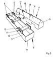
- eine Verdampfungseinrichtung mit abgesetztem Deckel,
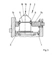
- Fig. 3
- einen Querschnitt durch eine Beschichtungsanlage
gemäß
Figur 1.
- Fig. 1
- an opened coating device with inserted evaporation device according to the invention,
- Fig. 2
- an evaporator with a separate lid,
- Fig. 3
- a cross section through a coating system according to Figure 1.
Zunächst wird auf die Figur 1 Bezug genommen. Man erkennt
den Bedampfungsraum 1 einer Beschichtungsanlage, der sich
schachtartig über die Breite der Anlage erstreckt. Mittels
nicht gezeigter Rollen wird die zu beschichtende Folienbahn
über die Bedampfungsraumöffnung geführt. In dem
Bedampfungsraum 1 befindet sich eine Verdampfungseinrichtung
2, bestehend aus zwei länglichen Wannen 3, die mit
ihren kurzen Seiten aneinander stoßen. In den Wannen 3
befindet sich das zu verdampfende Material 4, im vorliegenden
Fall Zinksulfid-Granulat, die als Schüttgut in die
Wanne eingebracht sind. Über jede Wanne 3 erstrecken sich
drei Heizstäbe 5, die in gleichmäßigem Abstand zueinander
angeordnet sind. Gehalten werden sie von Tragringen 6,
wobei die Enden der Heizstäbe 5 seitlich über die Wanne 3
herausragen und mit aus den Bedampfungsraumwänden
herausragenden Kontaktstempeln 7 kontaktiert werden können.
Die Wannen 3 werden mittels Deckeln geschlossen, die
in dieser Figur nicht gezeigt, aber in Figur 2 näher dargestellt
sind: Diese zeigt eine Wanne 3, wobei zur besseren
Verdeutlichung der zugehörige Deckel 8 seitlich abgesetzt
ist.First, reference is made to FIG. One recognises
the evaporation chamber 1 a coating system, which is
shaft-like extending over the width of the plant. through
not shown rolls is the film web to be coated
passed over the Bedampfungsraumöffnung. By doing
Die Wanne 3 ist ein quaderförmiger Hohlkörper, dessen
Oberseite vollständig offen ist, so dass ein rechteckig
umlaufender Wannenrand 9 vorhanden ist, der von den Rändern
der kurzen und langen Seitenwände 10 der Wanne 3 gebildet
wird.The
Wie schon erläutert, werden die Heizstäbe 5, die vorzugsweise
aus Graphit bestehen, in Tragringen 6 gehalten.
Diese sind rechteckig und weisen eine dem Querschnitt der
Heizstäbe 5 angepasste innere Öffnung 11 auf, durch die
das jeweilige Ende eines Heizstabes 5 hindurchgesteckt
ist. Der Außenrand der Tragringe 6 ist mit einer umlaufenden
Nut 12 versehen, die etwa so breit ist wie die
Bleche dick sind, aus denen die Wanne 3 und der Deckel 8
hergestellt sind. Die Heizstäbe 5 werden auf die Wanne 3
aufgesetzt, wobei der Wannenrand 9 in die Nuten 12 der
Tragringe 6 eingeführt wird.As already explained, the
Der neben der Wanne 3 gezeigte Deckel 8 hat die Form eines
mit einem Giebeldach versehenen Hauses, hat also zwei
rechteckige Seitenwände 13, zwei Dachschrägen 14 und zwei
Giebelwände 15. Die Dachschrägen 14 laufen im First des
Giebeldaches bis auf einen Schlitz zusammen, der als Austrittsschlitz
16 für den im Gehäuse erzeugten Dampf fungiert.The
Die Seitenwände 13 des Deckels 8 sind in etwa so hoch wie
die Tragringe 6 und verfügen über entsprechende rechteckige
randoffene Ausschnitte 17 , die der Form der
Tragringe 6 angepasst sind, so dass, wenn der Deckel aufgesetzt
wird, der Rand der Ausschnitte 17 in die Nut 12
an den Tragringen 6 eintaucht. Bei aufgesetztem Deckel 8
ergibt sich somit ein geschlossenes Gehäuse, das quer von
drei Heizstäben 5 durchsetzt ist und das an der Oberseite
über einen Austrittsschlitz 16 für den Austritt des erzeugten
Dampfes verfügt.The
Um dies nochmals zu verdeutlichen, zeigt die Figur 3 einen
Querschnitt durch die Verdampfungseinrichtung 2. Die
Kontur des von einer Wanne 3 und einem Deckel 8 gebildeten
Gehäuses entspricht im Querschnitt einem Rechteck, an
dessen kurzer Seite ein Dreieck angesetzt ist. Im oberen
Drittel des rechteckigen Gehäusebereiches wird das Gehäuse
von den Heizstäben 5 durchzogen, die im Querschnitt
rechteckig sind und mit ihren flachen Seite nach unten
weisen. In der Figur 3 ist links ein feststehender Kontaktstempel
7a zum Kontaktieren des aus dem Gehäuse herausragenden
einen Endes des Heizstabes 5 zu sehen. Auf
der anderen Seite befindet sich ein verfahrbarer Kontaktstempel
7b, der sich an das andere Ende des aus dem Gehäuse
herausragenden Heizstabes 5 anlegt. Über den Kontaktstempel
wird der Heizstab 5 an eine Stromversorgung
angeschlossen: Er heizt sich durch den hindurchfließenden
Strom auf, wobei seine Wärmeenergie in Form von Strahlungsleistung
insbesondere an das sich in der Wanne 3 befindende
Material 4 abgegeben wird, das daraufhin verdampft.To clarify this again, Figure 3 shows a
Cross section through the
Im Giebel des Deckels 8 befinden sich noch perforierte
Abdeckbleche 18, die zwar einen Durchtritt des Dampfes
erlauben, aber verhindern, dass Materialbrocken in den
Bedampfungsraum 1 ausgetragen werden. In the gable of the
- 11
- BedampfungsraumBedampfungsraum
- 22
- VerdampfungseinrichtungEvaporation device
- 33
- WannenPans
- 44
- Materialmaterial
- 55
- Heizstabheater
- 66
- Tragringsupport ring
- 77
- KontaktstempelContact temple
- 88th
- Deckelcover
- 99
- Randedge
- 1010
- SeitenwandSide wall
- 1111
- innere Öffnunginner opening
- 1212
- Nutgroove
- 1313
- Seitenwändeside walls
- 1414
- Dachschrägendroops
- 1515
- Giebelwändegable walls
- 1616
- Austrittsschlitzexit slot
- 1717
- randoffene Ausschnitteopen-edged cutouts
- 1818
- AbdeckblechCover plate
Claims (8)
Priority Applications (1)
| Application Number | Priority Date | Filing Date | Title |
|---|---|---|---|
| PL04004928T PL1555334T3 (en) | 2004-01-14 | 2004-03-03 | Vaporization equipment for material sublimation |
Applications Claiming Priority (2)
| Application Number | Priority Date | Filing Date | Title |
|---|---|---|---|
| DE102004001884A DE102004001884A1 (en) | 2004-01-14 | 2004-01-14 | Evaporator for sublimating materials |
| DE102004001884 | 2004-01-14 |
Publications (2)
| Publication Number | Publication Date |
|---|---|
| EP1555334A1 true EP1555334A1 (en) | 2005-07-20 |
| EP1555334B1 EP1555334B1 (en) | 2008-05-07 |
Family
ID=34609530
Family Applications (1)
| Application Number | Title | Priority Date | Filing Date |
|---|---|---|---|
| EP04004928A Expired - Lifetime EP1555334B1 (en) | 2004-01-14 | 2004-03-03 | Vaporization equipment for material sublimation |
Country Status (10)
| Country | Link |
|---|---|
| US (1) | US20050150975A1 (en) |
| EP (1) | EP1555334B1 (en) |
| JP (1) | JP2005200767A (en) |
| KR (1) | KR100642057B1 (en) |
| CN (1) | CN1333104C (en) |
| AT (1) | ATE394520T1 (en) |
| DE (2) | DE102004001884A1 (en) |
| PL (1) | PL1555334T3 (en) |
| RU (1) | RU2307877C2 (en) |
| TW (1) | TWI269816B (en) |
Families Citing this family (7)
| Publication number | Priority date | Publication date | Assignee | Title |
|---|---|---|---|---|
| JP5361467B2 (en) * | 2009-03-13 | 2013-12-04 | 東京エレクトロン株式会社 | Vaporizer |
| KR20140025795A (en) * | 2012-08-22 | 2014-03-05 | 에스엔유 프리시젼 주식회사 | Selective linear evaporating apparatus |
| KR102227546B1 (en) * | 2014-01-20 | 2021-03-15 | 주식회사 선익시스템 | Large capacity evaporation source and Deposition apparatus including the same |
| CN104404451A (en) * | 2014-12-16 | 2015-03-11 | 合肥鑫晟光电科技有限公司 | Evaporation source and evaporation device |
| CN105132866B (en) * | 2015-09-08 | 2018-02-16 | 京东方科技集团股份有限公司 | The heating source device and evaporator of a kind of evaporator |
| EP3559306B1 (en) * | 2016-12-22 | 2022-10-05 | Flisom AG | Linear source for vapor deposition with at least three electrical heating elements |
| CN108330444A (en) * | 2018-02-11 | 2018-07-27 | 常德金德新材料科技股份有限公司 | A method of preparing ZnS-film |
Citations (4)
| Publication number | Priority date | Publication date | Assignee | Title |
|---|---|---|---|---|
| JPS5943872A (en) * | 1982-09-04 | 1984-03-12 | Konishiroku Photo Ind Co Ltd | Vessel for storing material to be evaporated |
| EP0477474A1 (en) * | 1990-09-28 | 1992-04-01 | Mitsubishi Jukogyo Kabushiki Kaisha | Vacuum vapor deposition apparatus |
| EP0510259A1 (en) * | 1991-04-03 | 1992-10-28 | Mitsubishi Jukogyo Kabushiki Kaisha | Apparatus for vacuum deposition of a sublimable substance |
| US5239611A (en) * | 1991-02-14 | 1993-08-24 | Hilmar Weinert | Series evaporator |
Family Cites Families (12)
| Publication number | Priority date | Publication date | Assignee | Title |
|---|---|---|---|---|
| US3041493A (en) * | 1950-08-30 | 1962-06-26 | Sylvania Electric Prod | Electron discharge device |
| US3027150A (en) * | 1958-03-10 | 1962-03-27 | Hoerder Huettenunion Ag | Apparatus for treating steel melts |
| JPS5048855U (en) * | 1973-09-04 | 1975-05-14 | ||
| JPS5224050U (en) * | 1975-08-08 | 1977-02-19 | ||
| US4045638A (en) * | 1976-03-09 | 1977-08-30 | Bing Chiang | Continuous flow heat treating apparatus using microwaves |
| DE2723581C2 (en) * | 1977-03-08 | 1984-11-29 | Techtransfer GmbH, 7000 Stuttgart | Process for the aerobic rotting of animal excrement or sewage sludge as well as a system for carrying out the process |
| JPH0269961U (en) * | 1988-11-17 | 1990-05-28 | ||
| JP2583159B2 (en) * | 1991-02-08 | 1997-02-19 | 株式会社小松製作所 | Fluid heater |
| FR2693480B1 (en) * | 1992-07-08 | 1994-08-19 | Icbt Roanne | Heating device for a moving wire. |
| JPH11246963A (en) * | 1998-03-05 | 1999-09-14 | Nikon Corp | Boat for vapor deposition and optical thin film formed by using it |
| JP2000248358A (en) * | 1999-03-01 | 2000-09-12 | Casio Comput Co Ltd | Vapor deposition device and vapor deposition method |
| US20050034847A1 (en) * | 2003-08-11 | 2005-02-17 | Robert Graham | Monolithic tube sheet and method of manufacture |
-
2004
- 2004-01-14 DE DE102004001884A patent/DE102004001884A1/en not_active Ceased
- 2004-03-03 PL PL04004928T patent/PL1555334T3/en unknown
- 2004-03-03 DE DE502004007046T patent/DE502004007046D1/en not_active Expired - Lifetime
- 2004-03-03 AT AT04004928T patent/ATE394520T1/en not_active IP Right Cessation
- 2004-03-03 EP EP04004928A patent/EP1555334B1/en not_active Expired - Lifetime
- 2004-03-08 TW TW093106035A patent/TWI269816B/en not_active IP Right Cessation
- 2004-04-02 CN CNB2004100323466A patent/CN1333104C/en not_active Withdrawn - After Issue
- 2004-04-21 KR KR1020040027333A patent/KR100642057B1/en not_active IP Right Cessation
- 2004-12-01 US US11/001,528 patent/US20050150975A1/en not_active Abandoned
- 2004-12-22 RU RU2004137526/02A patent/RU2307877C2/en active
-
2005
- 2005-01-13 JP JP2005006628A patent/JP2005200767A/en active Pending
Patent Citations (4)
| Publication number | Priority date | Publication date | Assignee | Title |
|---|---|---|---|---|
| JPS5943872A (en) * | 1982-09-04 | 1984-03-12 | Konishiroku Photo Ind Co Ltd | Vessel for storing material to be evaporated |
| EP0477474A1 (en) * | 1990-09-28 | 1992-04-01 | Mitsubishi Jukogyo Kabushiki Kaisha | Vacuum vapor deposition apparatus |
| US5239611A (en) * | 1991-02-14 | 1993-08-24 | Hilmar Weinert | Series evaporator |
| EP0510259A1 (en) * | 1991-04-03 | 1992-10-28 | Mitsubishi Jukogyo Kabushiki Kaisha | Apparatus for vacuum deposition of a sublimable substance |
Non-Patent Citations (1)
| Title |
|---|
| PATENT ABSTRACTS OF JAPAN vol. 008, no. 134 (C - 230) 21 June 1984 (1984-06-21) * |
Also Published As
| Publication number | Publication date |
|---|---|
| CN1641066A (en) | 2005-07-20 |
| RU2307877C2 (en) | 2007-10-10 |
| CN1333104C (en) | 2007-08-22 |
| TWI269816B (en) | 2007-01-01 |
| KR20050074882A (en) | 2005-07-19 |
| EP1555334B1 (en) | 2008-05-07 |
| KR100642057B1 (en) | 2006-11-10 |
| JP2005200767A (en) | 2005-07-28 |
| PL1555334T3 (en) | 2008-10-31 |
| DE502004007046D1 (en) | 2008-06-19 |
| DE102004001884A1 (en) | 2005-08-11 |
| TW200523382A (en) | 2005-07-16 |
| ATE394520T1 (en) | 2008-05-15 |
| RU2004137526A (en) | 2006-06-10 |
| US20050150975A1 (en) | 2005-07-14 |
Similar Documents
| Publication | Publication Date | Title |
|---|---|---|
| DE2810440C3 (en) | Microwave tanning container | |
| DE2242581C3 (en) | Hollow sheet for building walls with variable thermal conductivity | |
| DE60318170T2 (en) | vacuum evaporator | |
| DE2847963A1 (en) | CONVECTION OVEN | |
| EP1555334B1 (en) | Vaporization equipment for material sublimation | |
| DE2058901A1 (en) | High frequency heater | |
| DE2917841A1 (en) | EVAPORATOR FOR VACUUM EVAPORATION SYSTEMS | |
| DE10346964B4 (en) | Dishwasher with variable heat insulation | |
| EP1862564A1 (en) | Apparatus for the evaporation of materials by means of an evaporator tube | |
| EP1662017B1 (en) | Apparatus for evaporation of materials | |
| EP1102010A1 (en) | Oven with steam generator | |
| EP1788113A1 (en) | Evaporator with a container for receiving the evaporation material | |
| DE2133119C3 (en) | incubator | |
| DE3100617A1 (en) | "STEAM IRON" | |
| EP3513622B1 (en) | Plastic made cassette with heating device | |
| DE102012206591B4 (en) | Vacuum substrate treatment plant | |
| DE102007047330A1 (en) | Heating device for a vacuum plant, comprises a heat-radiating surface, and a heat storage unit and/or heating element arranged parallel to the surface of the heat storage unit | |
| DE102013108403B4 (en) | Pass substrate treatment plant | |
| EP0269892B1 (en) | Device for heat retention, especially for food | |
| DE2402111B2 (en) | Series evaporator for vacuum evaporation systems | |
| DE4215385A1 (en) | Vacuum drying cupboard with heat flow passages in roof, floor and walls - shows min. risk of explosion and drying time for laboratory preparations | |
| DE1805246C3 (en) | Device for evaporation of metals under vacuum | |
| DE2221765A1 (en) | TILE STOVES, IN PARTICULAR FIRE-MOUNTED ELECTRICALLY HEATABLE TILE STOVES | |
| DE102021006249A1 (en) | Coating source, coating equipment and method for coating substrates | |
| EP1406056A1 (en) | Assembly of an installation for drying moisture loaded material |
Legal Events
| Date | Code | Title | Description |
|---|---|---|---|
| PUAI | Public reference made under article 153(3) epc to a published international application that has entered the european phase |
Free format text: ORIGINAL CODE: 0009012 |
|
| AK | Designated contracting states |
Kind code of ref document: A1 Designated state(s): AT BE BG CH CY CZ DE DK EE ES FI FR GB GR HU IE IT LI LU MC NL PL PT RO SE SI SK TR |
|
| AX | Request for extension of the european patent |
Extension state: AL LT LV MK |
|
| 17P | Request for examination filed |
Effective date: 20051111 |
|
| AKX | Designation fees paid |
Designated state(s): AT BE BG CH CY CZ DE DK EE ES FI FR GB GR HU IE IT LI LU MC NL PL PT RO SE SI SK TR |
|
| RAP1 | Party data changed (applicant data changed or rights of an application transferred) |
Owner name: APPLIED MATERIALS GMBH & CO. KG |
|
| GRAP | Despatch of communication of intention to grant a patent |
Free format text: ORIGINAL CODE: EPIDOSNIGR1 |
|
| GRAS | Grant fee paid |
Free format text: ORIGINAL CODE: EPIDOSNIGR3 |
|
| GRAA | (expected) grant |
Free format text: ORIGINAL CODE: 0009210 |
|
| AK | Designated contracting states |
Kind code of ref document: B1 Designated state(s): AT BE BG CH CY CZ DE DK EE ES FI FR GB GR HU IE IT LI LU MC NL PL PT RO SE SI SK TR |
|
| REG | Reference to a national code |
Ref country code: GB Ref legal event code: FG4D Free format text: NOT ENGLISH |
|
| REG | Reference to a national code |
Ref country code: CH Ref legal event code: EP |
|
| REG | Reference to a national code |
Ref country code: IE Ref legal event code: FG4D Free format text: LANGUAGE OF EP DOCUMENT: GERMAN |
|
| REF | Corresponds to: |
Ref document number: 502004007046 Country of ref document: DE Date of ref document: 20080619 Kind code of ref document: P |
|
| PG25 | Lapsed in a contracting state [announced via postgrant information from national office to epo] |
Ref country code: SI Free format text: LAPSE BECAUSE OF FAILURE TO SUBMIT A TRANSLATION OF THE DESCRIPTION OR TO PAY THE FEE WITHIN THE PRESCRIBED TIME-LIMIT Effective date: 20080507 |
|
| PG25 | Lapsed in a contracting state [announced via postgrant information from national office to epo] |
Ref country code: NL Free format text: LAPSE BECAUSE OF FAILURE TO SUBMIT A TRANSLATION OF THE DESCRIPTION OR TO PAY THE FEE WITHIN THE PRESCRIBED TIME-LIMIT Effective date: 20080507 Ref country code: ES Free format text: LAPSE BECAUSE OF FAILURE TO SUBMIT A TRANSLATION OF THE DESCRIPTION OR TO PAY THE FEE WITHIN THE PRESCRIBED TIME-LIMIT Effective date: 20080818 Ref country code: FI Free format text: LAPSE BECAUSE OF FAILURE TO SUBMIT A TRANSLATION OF THE DESCRIPTION OR TO PAY THE FEE WITHIN THE PRESCRIBED TIME-LIMIT Effective date: 20080507 |
|
| REG | Reference to a national code |
Ref country code: PL Ref legal event code: T3 |
|
| NLV1 | Nl: lapsed or annulled due to failure to fulfill the requirements of art. 29p and 29m of the patents act | ||
| REG | Reference to a national code |
Ref country code: IE Ref legal event code: FD4D |
|
| PG25 | Lapsed in a contracting state [announced via postgrant information from national office to epo] |
Ref country code: IE Free format text: LAPSE BECAUSE OF FAILURE TO SUBMIT A TRANSLATION OF THE DESCRIPTION OR TO PAY THE FEE WITHIN THE PRESCRIBED TIME-LIMIT Effective date: 20080507 Ref country code: PT Free format text: LAPSE BECAUSE OF FAILURE TO SUBMIT A TRANSLATION OF THE DESCRIPTION OR TO PAY THE FEE WITHIN THE PRESCRIBED TIME-LIMIT Effective date: 20081007 Ref country code: DK Free format text: LAPSE BECAUSE OF FAILURE TO SUBMIT A TRANSLATION OF THE DESCRIPTION OR TO PAY THE FEE WITHIN THE PRESCRIBED TIME-LIMIT Effective date: 20080507 Ref country code: SE Free format text: LAPSE BECAUSE OF FAILURE TO SUBMIT A TRANSLATION OF THE DESCRIPTION OR TO PAY THE FEE WITHIN THE PRESCRIBED TIME-LIMIT Effective date: 20080807 |
|
| PG25 | Lapsed in a contracting state [announced via postgrant information from national office to epo] |
Ref country code: SK Free format text: LAPSE BECAUSE OF FAILURE TO SUBMIT A TRANSLATION OF THE DESCRIPTION OR TO PAY THE FEE WITHIN THE PRESCRIBED TIME-LIMIT Effective date: 20080507 Ref country code: RO Free format text: LAPSE BECAUSE OF FAILURE TO SUBMIT A TRANSLATION OF THE DESCRIPTION OR TO PAY THE FEE WITHIN THE PRESCRIBED TIME-LIMIT Effective date: 20080507 |
|
| PLBE | No opposition filed within time limit |
Free format text: ORIGINAL CODE: 0009261 |
|
| STAA | Information on the status of an ep patent application or granted ep patent |
Free format text: STATUS: NO OPPOSITION FILED WITHIN TIME LIMIT |
|
| 26N | No opposition filed |
Effective date: 20090210 |
|
| PG25 | Lapsed in a contracting state [announced via postgrant information from national office to epo] |
Ref country code: EE Free format text: LAPSE BECAUSE OF FAILURE TO SUBMIT A TRANSLATION OF THE DESCRIPTION OR TO PAY THE FEE WITHIN THE PRESCRIBED TIME-LIMIT Effective date: 20080507 Ref country code: BG Free format text: LAPSE BECAUSE OF FAILURE TO SUBMIT A TRANSLATION OF THE DESCRIPTION OR TO PAY THE FEE WITHIN THE PRESCRIBED TIME-LIMIT Effective date: 20080807 |
|
| REG | Reference to a national code |
Ref country code: HU Ref legal event code: AG4A Ref document number: E004852 Country of ref document: HU |
|
| BERE | Be: lapsed |
Owner name: APPLIED MATERIALS G.M.B.H. & CO. KG Effective date: 20090331 |
|
| PG25 | Lapsed in a contracting state [announced via postgrant information from national office to epo] |
Ref country code: CZ Free format text: LAPSE BECAUSE OF NON-PAYMENT OF DUE FEES Effective date: 20090303 Ref country code: MC Free format text: LAPSE BECAUSE OF NON-PAYMENT OF DUE FEES Effective date: 20090331 |
|
| REG | Reference to a national code |
Ref country code: CH Ref legal event code: PL |
|
| REG | Reference to a national code |
Ref country code: FR Ref legal event code: ST Effective date: 20091130 |
|
| PG25 | Lapsed in a contracting state [announced via postgrant information from national office to epo] |
Ref country code: HU Free format text: LAPSE BECAUSE OF NON-PAYMENT OF DUE FEES Effective date: 20090304 Ref country code: LI Free format text: LAPSE BECAUSE OF NON-PAYMENT OF DUE FEES Effective date: 20090331 Ref country code: CH Free format text: LAPSE BECAUSE OF NON-PAYMENT OF DUE FEES Effective date: 20090331 |
|
| PG25 | Lapsed in a contracting state [announced via postgrant information from national office to epo] |
Ref country code: BE Free format text: LAPSE BECAUSE OF NON-PAYMENT OF DUE FEES Effective date: 20090331 |
|
| PG25 | Lapsed in a contracting state [announced via postgrant information from national office to epo] |
Ref country code: FR Free format text: LAPSE BECAUSE OF NON-PAYMENT OF DUE FEES Effective date: 20091123 |
|
| PG25 | Lapsed in a contracting state [announced via postgrant information from national office to epo] |
Ref country code: AT Free format text: LAPSE BECAUSE OF NON-PAYMENT OF DUE FEES Effective date: 20090303 |
|
| REG | Reference to a national code |
Ref country code: PL Ref legal event code: LAPE |
|
| PG25 | Lapsed in a contracting state [announced via postgrant information from national office to epo] |
Ref country code: PL Free format text: LAPSE BECAUSE OF NON-PAYMENT OF DUE FEES Effective date: 20090303 |
|
| PG25 | Lapsed in a contracting state [announced via postgrant information from national office to epo] |
Ref country code: GR Free format text: LAPSE BECAUSE OF FAILURE TO SUBMIT A TRANSLATION OF THE DESCRIPTION OR TO PAY THE FEE WITHIN THE PRESCRIBED TIME-LIMIT Effective date: 20080808 |
|
| PG25 | Lapsed in a contracting state [announced via postgrant information from national office to epo] |
Ref country code: LU Free format text: LAPSE BECAUSE OF NON-PAYMENT OF DUE FEES Effective date: 20090303 |
|
| PG25 | Lapsed in a contracting state [announced via postgrant information from national office to epo] |
Ref country code: TR Free format text: LAPSE BECAUSE OF FAILURE TO SUBMIT A TRANSLATION OF THE DESCRIPTION OR TO PAY THE FEE WITHIN THE PRESCRIBED TIME-LIMIT Effective date: 20080507 |
|
| PG25 | Lapsed in a contracting state [announced via postgrant information from national office to epo] |
Ref country code: CY Free format text: LAPSE BECAUSE OF FAILURE TO SUBMIT A TRANSLATION OF THE DESCRIPTION OR TO PAY THE FEE WITHIN THE PRESCRIBED TIME-LIMIT Effective date: 20080507 |
|
| REG | Reference to a national code |
Ref country code: DE Ref legal event code: R082 Ref document number: 502004007046 Country of ref document: DE Representative=s name: ZIMMERMANN & PARTNER PATENTANWAELTE MBB, DE Ref country code: DE Ref legal event code: R082 Ref document number: 502004007046 Country of ref document: DE Representative=s name: ZIMMERMANN & PARTNER, DE |
|
| PGFP | Annual fee paid to national office [announced via postgrant information from national office to epo] |
Ref country code: GB Payment date: 20190320 Year of fee payment: 16 Ref country code: IT Payment date: 20190325 Year of fee payment: 16 Ref country code: DE Payment date: 20190321 Year of fee payment: 16 |
|
| REG | Reference to a national code |
Ref country code: DE Ref legal event code: R119 Ref document number: 502004007046 Country of ref document: DE |
|
| PG25 | Lapsed in a contracting state [announced via postgrant information from national office to epo] |
Ref country code: DE Free format text: LAPSE BECAUSE OF NON-PAYMENT OF DUE FEES Effective date: 20201001 |
|
| GBPC | Gb: european patent ceased through non-payment of renewal fee |
Effective date: 20200303 |
|
| PG25 | Lapsed in a contracting state [announced via postgrant information from national office to epo] |
Ref country code: GB Free format text: LAPSE BECAUSE OF NON-PAYMENT OF DUE FEES Effective date: 20200303 |
|
| PG25 | Lapsed in a contracting state [announced via postgrant information from national office to epo] |
Ref country code: IT Free format text: LAPSE BECAUSE OF NON-PAYMENT OF DUE FEES Effective date: 20200303 |