EP1557150A2 - Curvilinear Spa - Google Patents
Curvilinear Spa Download PDFInfo
- Publication number
- EP1557150A2 EP1557150A2 EP04251070A EP04251070A EP1557150A2 EP 1557150 A2 EP1557150 A2 EP 1557150A2 EP 04251070 A EP04251070 A EP 04251070A EP 04251070 A EP04251070 A EP 04251070A EP 1557150 A2 EP1557150 A2 EP 1557150A2
- Authority
- EP
- European Patent Office
- Prior art keywords
- water
- spa
- ridge
- feature
- slope
- Prior art date
- Legal status (The legal status is an assumption and is not a legal conclusion. Google has not performed a legal analysis and makes no representation as to the accuracy of the status listed.)
- Granted
Links
- XLYOFNOQVPJJNP-UHFFFAOYSA-N water Substances O XLYOFNOQVPJJNP-UHFFFAOYSA-N 0.000 claims abstract description 87
- 238000000034 method Methods 0.000 claims description 6
- 239000003086 colorant Substances 0.000 claims 1
- 241000219793 Trifolium Species 0.000 abstract 1
- 239000011152 fibreglass Substances 0.000 description 4
- 239000000463 material Substances 0.000 description 4
- 239000002184 metal Substances 0.000 description 4
- NJPPVKZQTLUDBO-UHFFFAOYSA-N novaluron Chemical compound C1=C(Cl)C(OC(F)(F)C(OC(F)(F)F)F)=CC=C1NC(=O)NC(=O)C1=C(F)C=CC=C1F NJPPVKZQTLUDBO-UHFFFAOYSA-N 0.000 description 4
- 230000001225 therapeutic effect Effects 0.000 description 4
- 230000000007 visual effect Effects 0.000 description 4
- 239000002131 composite material Substances 0.000 description 3
- 238000002169 hydrotherapy Methods 0.000 description 3
- 239000002023 wood Substances 0.000 description 3
- 238000010276 construction Methods 0.000 description 2
- 238000001914 filtration Methods 0.000 description 2
- 238000004519 manufacturing process Methods 0.000 description 2
- 238000009428 plumbing Methods 0.000 description 2
- 208000027765 speech disease Diseases 0.000 description 2
- 238000002560 therapeutic procedure Methods 0.000 description 2
- 229910001335 Galvanized steel Inorganic materials 0.000 description 1
- 230000009286 beneficial effect Effects 0.000 description 1
- 230000001914 calming effect Effects 0.000 description 1
- 239000008397 galvanized steel Substances 0.000 description 1
- 239000003292 glue Substances 0.000 description 1
- 238000012986 modification Methods 0.000 description 1
- 230000004048 modification Effects 0.000 description 1
- 239000004033 plastic Substances 0.000 description 1
- 238000005086 pumping Methods 0.000 description 1
- 239000012858 resilient material Substances 0.000 description 1
- 230000003997 social interaction Effects 0.000 description 1
Images


Classifications
-
- A—HUMAN NECESSITIES
- A61—MEDICAL OR VETERINARY SCIENCE; HYGIENE
- A61H—PHYSICAL THERAPY APPARATUS, e.g. DEVICES FOR LOCATING OR STIMULATING REFLEX POINTS IN THE BODY; ARTIFICIAL RESPIRATION; MASSAGE; BATHING DEVICES FOR SPECIAL THERAPEUTIC OR HYGIENIC PURPOSES OR SPECIFIC PARTS OF THE BODY
- A61H33/00—Bathing devices for special therapeutic or hygienic purposes
- A61H33/0087—Therapeutic baths with agitated or circulated water
-
- A—HUMAN NECESSITIES
- A61—MEDICAL OR VETERINARY SCIENCE; HYGIENE
- A61H—PHYSICAL THERAPY APPARATUS, e.g. DEVICES FOR LOCATING OR STIMULATING REFLEX POINTS IN THE BODY; ARTIFICIAL RESPIRATION; MASSAGE; BATHING DEVICES FOR SPECIAL THERAPEUTIC OR HYGIENIC PURPOSES OR SPECIFIC PARTS OF THE BODY
- A61H33/00—Bathing devices for special therapeutic or hygienic purposes
- A61H33/02—Bathing devices for use with gas-containing liquid, or liquid in which gas is led or generated, e.g. carbon dioxide baths
-
- A—HUMAN NECESSITIES
- A61—MEDICAL OR VETERINARY SCIENCE; HYGIENE
- A61H—PHYSICAL THERAPY APPARATUS, e.g. DEVICES FOR LOCATING OR STIMULATING REFLEX POINTS IN THE BODY; ARTIFICIAL RESPIRATION; MASSAGE; BATHING DEVICES FOR SPECIAL THERAPEUTIC OR HYGIENIC PURPOSES OR SPECIFIC PARTS OF THE BODY
- A61H33/00—Bathing devices for special therapeutic or hygienic purposes
- A61H33/60—Components specifically designed for the therapeutic baths of groups A61H33/00
- A61H33/601—Inlet to the bath
-
- E—FIXED CONSTRUCTIONS
- E04—BUILDING
- E04H—BUILDINGS OR LIKE STRUCTURES FOR PARTICULAR PURPOSES; SWIMMING OR SPLASH BATHS OR POOLS; MASTS; FENCING; TENTS OR CANOPIES, IN GENERAL
- E04H4/00—Swimming or splash baths or pools
- E04H4/0018—Easily movable or transportable swimming pools
- E04H4/0031—Easily movable or transportable swimming pools with shell type elements
- E04H4/0037—Mono-shell type
-
- E—FIXED CONSTRUCTIONS
- E04—BUILDING
- E04H—BUILDINGS OR LIKE STRUCTURES FOR PARTICULAR PURPOSES; SWIMMING OR SPLASH BATHS OR POOLS; MASTS; FENCING; TENTS OR CANOPIES, IN GENERAL
- E04H4/00—Swimming or splash baths or pools
- E04H4/0018—Easily movable or transportable swimming pools
- E04H4/0043—Easily movable or transportable swimming pools mainly made of panels
- E04H4/005—Easily movable or transportable swimming pools mainly made of panels characterised by the framework for supporting the panels
-
- A—HUMAN NECESSITIES
- A61—MEDICAL OR VETERINARY SCIENCE; HYGIENE
- A61H—PHYSICAL THERAPY APPARATUS, e.g. DEVICES FOR LOCATING OR STIMULATING REFLEX POINTS IN THE BODY; ARTIFICIAL RESPIRATION; MASSAGE; BATHING DEVICES FOR SPECIAL THERAPEUTIC OR HYGIENIC PURPOSES OR SPECIFIC PARTS OF THE BODY
- A61H2201/00—Characteristics of apparatus not provided for in the preceding codes
- A61H2201/01—Constructive details
- A61H2201/0188—Illumination related features
-
- E—FIXED CONSTRUCTIONS
- E04—BUILDING
- E04H—BUILDINGS OR LIKE STRUCTURES FOR PARTICULAR PURPOSES; SWIMMING OR SPLASH BATHS OR POOLS; MASTS; FENCING; TENTS OR CANOPIES, IN GENERAL
- E04H4/00—Swimming or splash baths or pools
- E04H4/0018—Easily movable or transportable swimming pools
- E04H2004/0068—Easily movable or transportable swimming pools made of plastic shells or plastic elements including at least parts of walls and floors
Definitions
- Typical spas are designed around dimensional lumber and are usually very linear in shape. Some deviations do occur in certain models but only on one or two sides. Spas with very linear shell shapes require very linear frames that are easily constructed with dimensionally-squared lumber, like standard two-by-four or two-by-two lumber. As a consequence, traditional spas are very squared or rectangular. In a square or rectangular spa, rounded seating space is sacrificed as it is fit as best as possible into squared corners.
- Typical linear spas are very plain looking, especially when the cover is on and they are not in use.
- Linear spas are not architecturally pleasing and are usually not a focal point for the customers' landscape architecture. Accordingly, many spa owners hide their spas with landscaping or put them inside structures such as gazebos.
- the typical spa is designed with primarily with only hydrotherapy in mind. Some spa designs do provide an additional water feature, which usually entails a plumbing device to pump out water into the main body of water of the spa. These waterfalls are for mostly for visual effect, typically lit with lights or other optic features, and achieve a very artificial sound. Other spas also provide sound systems such as stereos, but these systems are also unnatural and can detract from the therapeutic aspects of the spa.
- a curvilinear spa shell provides for an aesthetically pleasing and functionally efficient spa form.
- a curvilinear spa shell includes a top edge that defines four rounded concave corners and four convex side walls connecting two of the concave corners. Each of the rounded corners preferably have a radius that exceeds twelve inches.
- the top edge of the spa is substantially symmetrical about an axis through the center of opposing side walls, as well as through the center of opposing concave corners.
- the curvilinear spa shell improves the seat placement efficiency, ingress and egress to and from the spa, and accommodates various therapeutic devices such as visual and audio therapy features.
- a water feature that may, but without limitation, be provided in the curvilinear spa and extending from one side wall into the interior of the spa for being a focal point for users of the spa.
- One example water feature includes a ridge in an interior area of the spa and having a top disposed at, or just below or above a water line of the spa.
- the water feature also includes a water inlet adjacent to the ridge and opposite a main body of water area in the interior area.
- the water inlet is disposed in the spa at a depth lower than the top of the ridge.
- the water feature also includes a slope descending from the top of the ridge in the direction of the water inlet.
- the slope includes a patterned top surface configured to interact with water flowing over the ridge, down the slope and toward the water inlet, to produce a pleasing running water sound.
- the water feature may also include a light feature that illuminates water on or near the slope to enhance the therapeutic effects of the water feature.
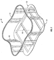
- FIG. 1 is an isometric view of a curvilinear spa.
- FIG. 2 is an isometric view of a curvilinear spa frame.
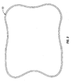
- FIG. 3 is a top view of the top rail of the spa frame.
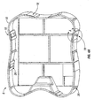
- FIG. 4A is an isometric view of another embodiment of the curvilinear spa
- FIG. 4B is an isometric view of a box section with panel and interlocking groove.
- FIG. 5 is a box section with truss.
- FIG. 6 is a top view of a curvilinear spa shell.
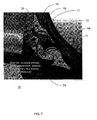
- FIG. 7 is a perspective view of a portion of a spa shell to illustrate a filter section.
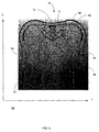
- FIG. 8 is a perspective view of a water feature.
- FIG. 1 depicts an embodiment of a curvilinear spa 2.
- Curvilinear spa 2 has an inner shell 4 that can hold water and includes support for spa users while experiencing the benefits of hydrotherapy.
- Bar top 6 substantially follows the contour of the curvilinear spa outline formed in part by the decorative siding 22.
- FIG. 2 depicts a curvilinear spa frame 8 that supports the curvilinear spa shell 4.
- the curvilinear spa frame 8 includes a top rail 10 and a bottom rail 12.
- the top rail 10 and bottom rail 12 substantially mimics the contour of the curvilinear spa 2.
- the top rail 10 and bottom rail 12 can be made of any material suitable for supporting the weight associated with the use of the shell 4, for example, wood, metal, composite materials like fiberglass, etc.
- the top rail 10 can be substantially the same shape as the bar top 6 and can support the weight associated with the bar top 6. During assembly, the top rail 10 can be aligned with and become an anchor for the bar top 6.
- the bottom rail 12 can be supported by a bottom pedestal 14 or similar support structure.
- the bottom pedestal 14 is used to give additional stability to the frame and like the top and bottom rail, can be made of any material capable of supporting the weight of the spa, like wood, metal, composite materials like fiberglass, etc.
- bottom beam 16 can be secured to the opposing sides of the bottom pedestal 14.
- Other similar fastening techniques can be utilized as well to secure the bottom rail 12, top rail 10 and bottom pedestal 14 in a predetermined manner in order to facilitate assembly and rigidity.
- Box sections 18 provide rigidity to the frame structure in addition to providing support to the top rail 10.
- Box sections 18 are substantially linear and can be spaced intermittently substantially within the confines of the outer diameter of the curvilinear frame 8 thereby alleviating the need for more complex shaped support structures that follow the complex contours of the curvilinear spa frame 8.
- Box sections 18 can be prefabricated and made of any material capable of supporting the weight associated with the spa 2, like metal, wood, composite materials like fiberglass, etc.
- FIG. 3 depicts a top view of the top rail 10.
- Top rail 10 can be formed as one piece, or alternately, can be formed from a multiplicity of pieces, e.g., fabricated using a CNC machine. When the pieces are fastened, the top rail 10 is formed and becomes a structurally sound support member for the bar top 6 (not shown). If a multiplicity of overlapping pieces are utilized to fabricate top rail 10, glue, staples, or other known fasteners can be used to create an integrated top rail 10 member.
- FIG. 4A and B depicts another embodiment of the curvilinear spa frame 8 that is easy to assemble and sufficiently rigid.
- the box sections 18 include a sheet 24 fastened in any known fashion to a rectangular structural member 26.
- use of the sheet 24 not only improves rigidity, but also assists with alignment of curvilinear spa frame components, e.g., the top rail 10 and bottom rail 12.
- the sheet 24 interlocks into notches in the top rail 10 and bottom rail 12.
- box section 18 can be readily inserted into the appropriate position between top rail 10 and bottom rail 12 thereby facilitating alignment of the top rail 10 and bottom rail 12.
- the notches can be located in various combinations of the top rail 10 and bottom rail 12, as long as the box section 18 assists alignment of the spa frame curvilinear components, e.g., the top rail 10 to the curvilinear bottom rail 12.
- Other fastening techniques can be utilized, e.g., predetermined placement of holes in the top and bottom rails with associated pegs on the top and bottom of the box section 12 (not shown). Additionally, strategic use of any modern fasteners, e.g., predetermined placement of pieces of sheet metal also may be used to ensure that corresponding box sections 18 are secured at corresponding predetermined locations in the curvilinear spa frame during assembly, thereby facilitating alignment of the curvilinear spa frame components.
- interlocking construction can be utilized, e.g., pegs and holes, interlocking sheet material and notches, etc.
- the interlocking construction can be located on any and/or all curvilinear frame components to improve rigidity and increase ease of assembly.
- additional supports 28, in this case 2x2s can be included in the curvilinear spa frame 8 as needed to increase rigidity.
- FIG. 5 depicts the use of truss plates 20 on box section 18. If more rigidity is desired, additional truss plates 20 can be added. Typically, truss plates are made of sheets of galvanized steel and are secured into the box sections using pressure during fabrication. Moreover, increasing the strength of the box sections 18 may advantageously reduce the number of box sections 18 required to maintain the rigidity associated with the spa 2. To further reduce the number of box sections 18 required, additional supports 28 as depicted in FIG. 4A can be added.
- FIG. 6 is a two-dimensional, top-down view of a curvilinear spa shell 60.
- the spa shell 60 can be substantially the same size as a conventional square linear spa.
- the general contours of the spa shell 60 are defined by a top edge 68 that includes four substantially identical rounded corners 62 that are concave relative to an interior of the spa shell 60.
- the four corners 62 are connected to seamlessly form four side walls 64 that are convex relative to the interior of the shell 60.
- the contour of the spa shell 60 is symmetrical about both the x and y axes (i.e. through the middle of opposing side walls 64), as well as symmetrical along an axis through the middle of opposing corners 62.
- the rounded corners 62 are formed with large interior radii, each radius preferably exceeding twelve inches, which produces a more efficient and effective seat design.
- Each rounded corner 62 can include a large seat 66 that can have many different configurations for accommodating various therapeutic devices and/or various sizes of users. Further, the location and orientation of each seat 66 within its respective corner 62 promotes multi-user alignment for increased social interaction, yet maximizes the space between the seats.
- the seat arrangement also provides easier ingress and egress from a spa constructed with the spa shell 60.
- the side walls 64 between the corners 62 provide a large area for a user to enter or exit the spa, and one or more of the side walls 64 may include one or more internal steps or ridges.
- one or more side walls 64 may include a small seat (not shown). Such a small seat can be positioned in the spa shell 60 such that it is more shallow than the large seats 66, thereby acting as a step to assist ingress and egress.
- the top edge 68 defines the overall shape and form of the curvilinear design.
- the top edge 68 defines the four concave rounded corners 62 as well as the four convex side walls 64, and can receive a similarly-shaped spa cover (not shown) that continues the clover-leaf shape.
- the spa shell 60 below the top edge 68 can accommodate a number of contoured seats 66, and other spa features such as therapy jets, heater outlets, filter inlets, user controls, etc.
- the spa shell 60 can be made of a unitary layer of resilient material, such as thermoformed plastic or fiberglass.
- the spa shell 60 below the top edge 68 can have an outer surface that maintains the overall general curvilinear contours defined by the top edge 68, as well as an inner surface that fits within the general contour but provides the various spa features.
- a filter section 70 having one or more water inlets 71 extends from one side wall 64 between two corners 62 and out toward the center of the spa shell 60.
- the water inlets 71 lead from the spa's main body for holding water to the spa's plumbing and/or filtering system.
- a filter (not shown) can be placed in front of a water inlet 71 from the perspective of the interior of the spa.
- the filter section 70 is disposed so as to be a focal point within the interior of the spa shell 60.
- the location and orientation of the filter section 70 in the spa shell 60 allows the filter section 70 to host, for optimal placement and use, one or more water features 72, such as a fountain or a "babbling brook" as described below.
- the filter section 70 may also host a light or array of lights, user controls, or a stereo control or other audio system.
- This particular curvilinear design of the spa shell 60 can use a number of the same shell components in different areas because of its symmetry, and thus simplifies the manufacturing and component inventory control processes. Further, the design provides an agreeable aesthetic that is not provided by conventional spa designs. Thus, a spa that utilizes the curvilinear spa shell 60 will be an architectural and aesthetically-pleasing feature in addition to being therapeutically beneficial
- FIG. 7 is a perspective view of a portion of a spa shell 60 showing a filter section 70 that also includes a water feature 72.
- the filter section 70 includes one or more water inlets 71, i.e. an inlet to a filter or a pump, etc.
- the water inlets 71 are disposed along a side wall 64 of the spa shell and separated from the spa interior by a ridge 74.
- the ridge 74 may be linear or curved, and may be at or below or above a water line defined for the spa shell 60.
- the ridge 74 may extend at least part way around the water inlets 71.
- the water feature 72 is disposed adjacent to the one or more water inlets 71.
- the water feature 72 includes a slope 78 descending from the ridge 74 to the side wall 64 at which the slope 78 is lower than the top of the ridge 74.
- the slope 78 may include grooves and/or a number of protrusions 79, such as a number of various sizes of bumps.
- one water inlet 71 is positioned on either side of the slope 78 between the ridge 74 and the side wall 64.
- water is either drawn in to the water inlets 71, or provided by an outlet (not shown) on the ridge 74, causing the water to travel over the ridge 74 and down the slope 78, and interact with the protrusions 79 and/or grooves to create a natural "babbling brook" sound.
- the length and angle of the slope 78 can be adjustable or varied in order to produce different sounds.
- the water flow rate may also be varied by, among other techniques, adjusting the flow rate into the water inlets 71, adjusting the height of the ridge 74, and/or adjusting the number and size of the protrusions 79 or grooves within the slope 78.
- the water feature 72 can also include a light feature 76 such as an array of LEDs or the like. The light feature 76 illuminates an area around the water flowing over the ridge 74 and down the slope 78 for a pleasing visual effect.
- FIG. 8 shows a perspective of a slope 78 having a patterned top surface 80 in the form of a number of raised bumps 79 and curved grooves 82.
- the bumps 79 can be any size or geometry, such as squared, rounded, or angular.
- the grooves 82 can be any size, depth, length, or shape.
- the patterned top surface 80 of the slope 78 therefore can have a random "natural" look, or have a more ordered arranged look, depending on aesthetic preference.
- the feature 72 can create a calming sound of running water as it interacts with the patterned top surface 80 of the slope 78.
- the light feature 76 can create a pleasurable visual effect that can be experienced by a user whether or not the user is actually looking directly at the light feature 76.
Abstract
Description
- Typical spas are designed around dimensional lumber and are usually very linear in shape. Some deviations do occur in certain models but only on one or two sides. Spas with very linear shell shapes require very linear frames that are easily constructed with dimensionally-squared lumber, like standard two-by-four or two-by-two lumber. As a consequence, traditional spas are very squared or rectangular. In a square or rectangular spa, rounded seating space is sacrificed as it is fit as best as possible into squared corners.
- Typical linear spas are very plain looking, especially when the cover is on and they are not in use. Linear spas are not architecturally pleasing and are usually not a focal point for the customers' landscape architecture. Accordingly, many spa owners hide their spas with landscaping or put them inside structures such as gazebos.
- The typical spa is designed with primarily with only hydrotherapy in mind. Some spa designs do provide an additional water feature, which usually entails a plumbing device to pump out water into the main body of water of the spa. These waterfalls are for mostly for visual effect, typically lit with lights or other optic features, and achieve a very artificial sound. Other spas also provide sound systems such as stereos, but these systems are also unnatural and can detract from the therapeutic aspects of the spa.
- Another limitation in most spa designs is ingress and egress. Spas rarely have internal steps because they sacrifice too much seating area. Coupled with the awkward seat configurations found in most linear spas, ingress and egress for a user of a typical spa is difficult. Yet another limitation in typical spa designs is the placement and functionality of the filter bucket. Most filter buckets occupy a "dead area," i.e., an area of the spa that cannot be utilized for hydrotherapy or other uses. Because of their single function of continuously receiving large amounts of water for filtering and pumping, filter buckets are not conceived of as an aesthetic element of the overall spa design.
- A curvilinear spa shell provides for an aesthetically pleasing and functionally efficient spa form. In one embodiment, a curvilinear spa shell includes a top edge that defines four rounded concave corners and four convex side walls connecting two of the concave corners. Each of the rounded corners preferably have a radius that exceeds twelve inches. The top edge of the spa is substantially symmetrical about an axis through the center of opposing side walls, as well as through the center of opposing concave corners.
- The curvilinear spa shell improves the seat placement efficiency, ingress and egress to and from the spa, and accommodates various therapeutic devices such as visual and audio therapy features. In one example, a water feature that may, but without limitation, be provided in the curvilinear spa and extending from one side wall into the interior of the spa for being a focal point for users of the spa.
- One example water feature includes a ridge in an interior area of the spa and having a top disposed at, or just below or above a water line of the spa. The water feature also includes a water inlet adjacent to the ridge and opposite a main body of water area in the interior area. The water inlet is disposed in the spa at a depth lower than the top of the ridge. The water feature also includes a slope descending from the top of the ridge in the direction of the water inlet. The slope includes a patterned top surface configured to interact with water flowing over the ridge, down the slope and toward the water inlet, to produce a pleasing running water sound. The water feature may also include a light feature that illuminates water on or near the slope to enhance the therapeutic effects of the water feature.
- The details of one or more embodiments are set forth in the accompanying drawings and the description below. Other features, objects, and advantages will be apparent from the description and drawings, and from the claims.
- These and other aspects will now be described in detail with reference to the following drawings.
- FIG. 1 is an isometric view of a curvilinear spa.
- FIG. 2 is an isometric view of a curvilinear spa frame.
- FIG. 3 is a top view of the top rail of the spa frame.
- FIG. 4A is an isometric view of another embodiment of the curvilinear spa
- FIG. 4B is an isometric view of a box section with panel and interlocking groove.
- FIG. 5 is a box section with truss.
- FIG. 6 is a top view of a curvilinear spa shell.
- FIG. 7 is a perspective view of a portion of a spa shell to illustrate a filter section.
- FIG. 8 is a perspective view of a water feature.
- Like reference symbols in the various drawings indicate like elements.
- FIG. 1 depicts an embodiment of a curvilinear spa 2. Curvilinear spa 2 has an
inner shell 4 that can hold water and includes support for spa users while experiencing the benefits of hydrotherapy.Bar top 6 substantially follows the contour of the curvilinear spa outline formed in part by thedecorative siding 22. - FIG. 2 depicts a
curvilinear spa frame 8 that supports thecurvilinear spa shell 4. As depicted in FIG. 2, thecurvilinear spa frame 8 includes atop rail 10 and abottom rail 12. Thetop rail 10 andbottom rail 12 substantially mimics the contour of the curvilinear spa 2. Thetop rail 10 andbottom rail 12 can be made of any material suitable for supporting the weight associated with the use of theshell 4, for example, wood, metal, composite materials like fiberglass, etc. Thetop rail 10 can be substantially the same shape as thebar top 6 and can support the weight associated with thebar top 6. During assembly, thetop rail 10 can be aligned with and become an anchor for thebar top 6. - As depicted in FIG. 2, the
bottom rail 12 can be supported by abottom pedestal 14 or similar support structure. Thebottom pedestal 14 is used to give additional stability to the frame and like the top and bottom rail, can be made of any material capable of supporting the weight of the spa, like wood, metal, composite materials like fiberglass, etc. For additional rigidity,bottom beam 16 can be secured to the opposing sides of thebottom pedestal 14. Other similar fastening techniques can be utilized as well to secure thebottom rail 12,top rail 10 andbottom pedestal 14 in a predetermined manner in order to facilitate assembly and rigidity. - As shown in FIG. 2, between
top rail 10 andbottom rail 12 is a plurality ofbox sections 18.Box sections 18 provide rigidity to the frame structure in addition to providing support to thetop rail 10.Box sections 18 are substantially linear and can be spaced intermittently substantially within the confines of the outer diameter of thecurvilinear frame 8 thereby alleviating the need for more complex shaped support structures that follow the complex contours of thecurvilinear spa frame 8.Box sections 18 can be prefabricated and made of any material capable of supporting the weight associated with the spa 2, like metal, wood, composite materials like fiberglass, etc. - FIG. 3 depicts a top view of the
top rail 10.Top rail 10 can be formed as one piece, or alternately, can be formed from a multiplicity of pieces, e.g., fabricated using a CNC machine. When the pieces are fastened, thetop rail 10 is formed and becomes a structurally sound support member for the bar top 6 (not shown). If a multiplicity of overlapping pieces are utilized to fabricatetop rail 10, glue, staples, or other known fasteners can be used to create an integratedtop rail 10 member. - FIG. 4A and B depicts another embodiment of the
curvilinear spa frame 8 that is easy to assemble and sufficiently rigid. As seen in FIG. 4A, thebox sections 18 include asheet 24 fastened in any known fashion to a rectangularstructural member 26. As depicted in FIG. 4B, use of thesheet 24 not only improves rigidity, but also assists with alignment of curvilinear spa frame components, e.g., thetop rail 10 andbottom rail 12. As depicted in FIG. 4B, thesheet 24 interlocks into notches in thetop rail 10 andbottom rail 12. As a result,box section 18 can be readily inserted into the appropriate position betweentop rail 10 andbottom rail 12 thereby facilitating alignment of thetop rail 10 andbottom rail 12. The notches can be located in various combinations of thetop rail 10 andbottom rail 12, as long as thebox section 18 assists alignment of the spa frame curvilinear components, e.g., thetop rail 10 to thecurvilinear bottom rail 12. Other fastening techniques can be utilized, e.g., predetermined placement of holes in the top and bottom rails with associated pegs on the top and bottom of the box section 12 (not shown). Additionally, strategic use of any modern fasteners, e.g., predetermined placement of pieces of sheet metal also may be used to ensure thatcorresponding box sections 18 are secured at corresponding predetermined locations in the curvilinear spa frame during assembly, thereby facilitating alignment of the curvilinear spa frame components. Those of skill in the art will appreciate the fact that many different types of interlocking construction can be utilized, e.g., pegs and holes, interlocking sheet material and notches, etc. The interlocking construction can be located on any and/or all curvilinear frame components to improve rigidity and increase ease of assembly. As depicted in FIG. 4A,additional supports 28, in this case 2x2s, can be included in thecurvilinear spa frame 8 as needed to increase rigidity. - To further increase structural rigidity, FIG. 5 depicts the use of
truss plates 20 onbox section 18. If more rigidity is desired,additional truss plates 20 can be added. Typically, truss plates are made of sheets of galvanized steel and are secured into the box sections using pressure during fabrication. Moreover, increasing the strength of thebox sections 18 may advantageously reduce the number ofbox sections 18 required to maintain the rigidity associated with the spa 2. To further reduce the number ofbox sections 18 required,additional supports 28 as depicted in FIG. 4A can be added. - FIG. 6 is a two-dimensional, top-down view of a
curvilinear spa shell 60. Thespa shell 60 can be substantially the same size as a conventional square linear spa. The general contours of thespa shell 60 are defined by atop edge 68 that includes four substantially identicalrounded corners 62 that are concave relative to an interior of thespa shell 60. The fourcorners 62 are connected to seamlessly form fourside walls 64 that are convex relative to the interior of theshell 60. The contour of thespa shell 60 is symmetrical about both the x and y axes (i.e. through the middle of opposing side walls 64), as well as symmetrical along an axis through the middle of opposingcorners 62. - The
rounded corners 62 are formed with large interior radii, each radius preferably exceeding twelve inches, which produces a more efficient and effective seat design. Eachrounded corner 62 can include alarge seat 66 that can have many different configurations for accommodating various therapeutic devices and/or various sizes of users. Further, the location and orientation of eachseat 66 within itsrespective corner 62 promotes multi-user alignment for increased social interaction, yet maximizes the space between the seats. - The seat arrangement also provides easier ingress and egress from a spa constructed with the
spa shell 60. For instance, theside walls 64 between thecorners 62 provide a large area for a user to enter or exit the spa, and one or more of theside walls 64 may include one or more internal steps or ridges. Alternatively, one ormore side walls 64 may include a small seat (not shown). Such a small seat can be positioned in thespa shell 60 such that it is more shallow than thelarge seats 66, thereby acting as a step to assist ingress and egress. - The
top edge 68 defines the overall shape and form of the curvilinear design. Thetop edge 68 defines the four concaverounded corners 62 as well as the fourconvex side walls 64, and can receive a similarly-shaped spa cover (not shown) that continues the clover-leaf shape. Thespa shell 60 below thetop edge 68 can accommodate a number of contouredseats 66, and other spa features such as therapy jets, heater outlets, filter inlets, user controls, etc. Thespa shell 60 can be made of a unitary layer of resilient material, such as thermoformed plastic or fiberglass. Thus, thespa shell 60 below thetop edge 68 can have an outer surface that maintains the overall general curvilinear contours defined by thetop edge 68, as well as an inner surface that fits within the general contour but provides the various spa features. - A
filter section 70 having one ormore water inlets 71 extends from oneside wall 64 between twocorners 62 and out toward the center of thespa shell 60. The water inlets 71 lead from the spa's main body for holding water to the spa's plumbing and/or filtering system. Thus, a filter (not shown) can be placed in front of awater inlet 71 from the perspective of the interior of the spa. Thefilter section 70 is disposed so as to be a focal point within the interior of thespa shell 60. The location and orientation of thefilter section 70 in thespa shell 60 allows thefilter section 70 to host, for optimal placement and use, one or more water features 72, such as a fountain or a "babbling brook" as described below. Thefilter section 70 may also host a light or array of lights, user controls, or a stereo control or other audio system. - This particular curvilinear design of the
spa shell 60 can use a number of the same shell components in different areas because of its symmetry, and thus simplifies the manufacturing and component inventory control processes. Further, the design provides an agreeable aesthetic that is not provided by conventional spa designs. Thus, a spa that utilizes thecurvilinear spa shell 60 will be an architectural and aesthetically-pleasing feature in addition to being therapeutically beneficial - FIG. 7 is a perspective view of a portion of a
spa shell 60 showing afilter section 70 that also includes awater feature 72. Thefilter section 70 includes one ormore water inlets 71, i.e. an inlet to a filter or a pump, etc. The water inlets 71 are disposed along aside wall 64 of the spa shell and separated from the spa interior by aridge 74. Theridge 74 may be linear or curved, and may be at or below or above a water line defined for thespa shell 60. Theridge 74 may extend at least part way around thewater inlets 71. Thewater feature 72 is disposed adjacent to the one ormore water inlets 71. In one example, thewater feature 72 includes aslope 78 descending from theridge 74 to theside wall 64 at which theslope 78 is lower than the top of theridge 74. Theslope 78 may include grooves and/or a number ofprotrusions 79, such as a number of various sizes of bumps. In the example, onewater inlet 71 is positioned on either side of theslope 78 between theridge 74 and theside wall 64. - In operation, water is either drawn in to the
water inlets 71, or provided by an outlet (not shown) on theridge 74, causing the water to travel over theridge 74 and down theslope 78, and interact with theprotrusions 79 and/or grooves to create a natural "babbling brook" sound. The length and angle of theslope 78 can be adjustable or varied in order to produce different sounds. The water flow rate may also be varied by, among other techniques, adjusting the flow rate into thewater inlets 71, adjusting the height of theridge 74, and/or adjusting the number and size of theprotrusions 79 or grooves within theslope 78. Thewater feature 72 can also include alight feature 76 such as an array of LEDs or the like. Thelight feature 76 illuminates an area around the water flowing over theridge 74 and down theslope 78 for a pleasing visual effect. - FIG. 8 shows a perspective of a
slope 78 having a patternedtop surface 80 in the form of a number of raisedbumps 79 andcurved grooves 82. Thebumps 79 can be any size or geometry, such as squared, rounded, or angular. Thegrooves 82 can be any size, depth, length, or shape. The patternedtop surface 80 of theslope 78 therefore can have a random "natural" look, or have a more ordered arranged look, depending on aesthetic preference. Thefeature 72 can create a calming sound of running water as it interacts with the patternedtop surface 80 of theslope 78. Thelight feature 76 can create a pleasurable visual effect that can be experienced by a user whether or not the user is actually looking directly at thelight feature 76. - Although a few embodiments have been described in detail above, other modifications are possible. Other embodiments may be within the scope of the following claims.
Claims (15)
- A water feature for a spa, comprising:a ridge in an interior area of the spa and having a top disposed near a water line of the spa;a water inlet adjacent to the ridge opposite a main body of water area in the interior area, the water inlet being placed lower than the top of the ridge; anda slope descending from the top of the ridge in the direction of the water inlet, the slope having a patterned top surface configured to interact with water flowing over the ridge, down the slope and toward the water inlet.
- The water feature in accordance with claim 1, further comprising a first water inlet and a second water inlet disposed on opposite sides of the slope.
- The water feature in accordance with claim 1, wherein the water inlet is adjacent to a side wall of the spa, and wherein the slope descends to the side wall at a position lower than the top of the ridge.
- The water feature in accordance with claim 1, wherein the ridge is curved, and at least partially curves around the water inlet.
- The water feature in accordance with claim 1, wherein the slope includes one or more protrusions.
- The water feature in accordance with claim 1, wherein the slope includes one or more grooves.
- The water feature in accordance with claim 1, wherein an angle of the slope is adjustable.
- The water feature in accordance with claim 5, wherein a size of at least one of the one or more protrusions is adjustable.
- The water feature in accordance with claim 1, further comprising a light feature disposed at or near the top of the ridge, and configured to provide light to the water flowing over the ridge and/or down the slope.
- The water feature in accordance with claim 9, wherein the light feature includes a plurality of light emitting diodes (LEDs).
- The water feature in accordance with claim 9, wherein the light feature includes one or more colors.
- A method of providing an audibly pleasing sound with water in a spa, the method comprising:flowing water over a top of a ridge in an interior area of the spa and disposed at or below a water line;flowing water down a slope descending from the top of the ridge to a level below the top of the ridge, the slope having a patterned top surface configured to interact with water; andinteracting water with the patterned top surface to produce a flowing water sound.
- A curvilinear spa shell, comprising:a top edge defining four rounded concave corners each having a radius that exceeds twelve inches, and four convex side walls connecting two of the concave corners;wherein the top edge is substantially symmetrical about an axis through the center of opposing side walls; andwherein the top edge is substantially symmetrical about an axis through the center of opposing concave corners.
- The curvilinear spa shell in accordance with claim 13, further comprising a water feature.
- The curvilinear spa shell in accordance with claim 13, further comprising a filter section that extends from one side wall between two concave corners and toward the center of the top edge.
Applications Claiming Priority (2)
| Application Number | Priority Date | Filing Date | Title |
|---|---|---|---|
| US10/702,198 US20040088785A1 (en) | 2002-10-23 | 2003-11-04 | Curvilinear spa |
| US702198 | 2003-11-04 |
Publications (3)
| Publication Number | Publication Date |
|---|---|
| EP1557150A2 true EP1557150A2 (en) | 2005-07-27 |
| EP1557150A3 EP1557150A3 (en) | 2008-10-01 |
| EP1557150B1 EP1557150B1 (en) | 2011-06-29 |
Family
ID=34590704
Family Applications (1)
| Application Number | Title | Priority Date | Filing Date |
|---|---|---|---|
| EP04251070A Expired - Lifetime EP1557150B1 (en) | 2003-11-04 | 2004-02-26 | Curvilinear Spa |
Country Status (4)
| Country | Link |
|---|---|
| US (3) | US20040088785A1 (en) |
| EP (1) | EP1557150B1 (en) |
| AT (1) | ATE514409T1 (en) |
| AU (1) | AU2004202385B2 (en) |
Families Citing this family (5)
| Publication number | Priority date | Publication date | Assignee | Title |
|---|---|---|---|---|
| US20040088785A1 (en) * | 2002-10-23 | 2004-05-13 | Walker Victor Lee | Curvilinear spa |
| CN104652860B (en) * | 2014-12-23 | 2018-01-30 | 明达实业(厦门)有限公司 | Moveable water pool with a plurality of water storage cavities |
| US10969095B2 (en) | 2017-04-10 | 2021-04-06 | Masterspas, Llc | Lighting system and method |
| USD839983S1 (en) * | 2017-07-24 | 2019-02-05 | The Shrunks | Inflatable basin |
| US11052785B2 (en) * | 2017-12-19 | 2021-07-06 | Ramprasadh Selvarajah | Seating arrangement of an autonomous automobile |
Citations (1)
| Publication number | Priority date | Publication date | Assignee | Title |
|---|---|---|---|---|
| DE8631326U1 (en) | 1986-11-22 | 1988-01-07 | Kayser, Burkhard, 2906 Wardenburg, De |
Family Cites Families (53)
| Publication number | Priority date | Publication date | Assignee | Title |
|---|---|---|---|---|
| US172605A (en) * | 1876-01-25 | Improvement in bath-tubs | ||
| US2417499A (en) * | 1944-06-28 | 1947-03-18 | Floyd W Ille | Therapeutic bath |
| US3317927A (en) * | 1964-10-30 | 1967-05-09 | Eugene H Shields | Swimming pool construction |
| US3579665A (en) | 1967-10-11 | 1971-05-25 | Reynolds Metals Co | Swimming pool structure |
| US3579599A (en) * | 1967-11-21 | 1971-05-18 | Japan Gas Chemical Co | Process for extract-separation of aromatic hydrocarbons |
| US3644726A (en) * | 1969-10-29 | 1972-02-22 | Patent Service Corp Of America | Liquid cascade apparatus |
| US3736599A (en) * | 1971-03-25 | 1973-06-05 | Carson B | Swimming pool construction |
| US3869736A (en) * | 1971-04-13 | 1975-03-11 | Valmar Swimming Pools Ltd | Collapsible swimming pool |
| US3974605A (en) * | 1974-06-10 | 1976-08-17 | Elcon Manufacturing Company Limited | Wall structure and swimming pool construction |
| US3824635A (en) * | 1973-08-13 | 1974-07-23 | M Spaulding | Circulating hand-hold for swimming pools |
| US3913332A (en) * | 1973-08-30 | 1975-10-21 | Arnold H Forsman | Continuous wave surfing facility |
| US4050104A (en) * | 1975-05-22 | 1977-09-27 | Baker William H | Two-in-one perimeter gutter for swimming pools |
| US4206522A (en) * | 1975-12-15 | 1980-06-10 | Baker William H | Automated surge weir and rim skimming gutter flow control system |
| US4055922A (en) * | 1976-09-24 | 1977-11-01 | Heldor Associates, Inc. | Frame structure for swimming pool |
| US4233694A (en) * | 1979-01-22 | 1980-11-18 | Jacuzzi Whirlpool Bath, Inc. | Spa construction and isolated controls therefor |
| USD280342S (en) * | 1983-07-18 | 1985-08-27 | Kohler Co. | Hydrotherapy spa or the like |
| USD283545S (en) * | 1984-01-09 | 1986-04-22 | Kohler Co. | Combined cloverleaf spa and table therefor |
| GB2178655B (en) * | 1985-07-23 | 1988-09-14 | Donald Chisholm | Improved reservoirs |
| US4637873A (en) * | 1985-12-16 | 1987-01-20 | Jacuzzi Inc. | Front load skimmer/filter for spas and pools |
| US4747538A (en) * | 1986-03-10 | 1988-05-31 | Delta Tech, Inc. | Water wall |
| US4828626A (en) * | 1986-08-15 | 1989-05-09 | Crystal Pools, Inc. | Cleaning system for swimming pools and the like |
| US4847926A (en) * | 1987-05-11 | 1989-07-18 | Home & Roam Leisure Inc. | Swimming pool liner retaining bracket |
| US5186351A (en) * | 1988-08-05 | 1993-02-16 | San Joaquin Valley Express | Slurry tank |
| US4881280A (en) * | 1988-12-02 | 1989-11-21 | Lesikar Fred C | Waterfall producing unit for use in swimming pools |
| DE3901036C1 (en) * | 1989-01-14 | 1989-12-21 | Willi Pauli | Support frame for corner fitted bath tub or shower - has girders radiating from nodal sheet metal plate supporting corner strut |
| US5054135A (en) * | 1989-12-15 | 1991-10-08 | Vogue Industries Ltd. | Above ground pool |
| US5333325A (en) * | 1991-01-17 | 1994-08-02 | American Standard Inc. | Bathtub apron system |
| US5167368A (en) * | 1991-10-16 | 1992-12-01 | John Nash | Decorative waterfall |
| US5236581A (en) * | 1992-04-07 | 1993-08-17 | Conway Products Corporation | Spa with filter assembly accessible through its coping lip |
| CA2066339C (en) * | 1992-04-16 | 1995-04-11 | Kerry Cornelius | Pool wall construction |
| AU3992993A (en) * | 1992-11-06 | 1994-05-19 | Chartier, Clifford E | Apparatus for producing sheet waterfall for pool or spa |
| IT231804Y1 (en) * | 1993-09-27 | 1999-08-06 | Valerio Bresolin | INTERNAL CORNER FILTER, ESPECIALLY FOR SMALL TANKS AND AQUARIUMS |
| US5571409A (en) * | 1994-08-22 | 1996-11-05 | Scarborough; Jerry L. | Aquarium waterfall assembly |
| US5501178A (en) * | 1995-07-19 | 1996-03-26 | Kemp; Kay G. | Pet watering apparatus with flowing water to simulate a mountain creek |
| US5799345A (en) * | 1996-06-10 | 1998-09-01 | Softub, Inc. | Spa apparatus with multiple sections |
| US6170094B1 (en) * | 1998-01-07 | 2001-01-09 | Thermocraft Ind. Inc. | Modular waterfall apparatus and method |
| US6226938B1 (en) * | 1998-08-19 | 2001-05-08 | Linda M. Hodak | Concrete pool deck and pool wall support for swimming pool construction |
| US6094877A (en) * | 1998-08-24 | 2000-08-01 | White; Charles L. | Frame support assembly and method for curved walls |
| USD435297S (en) * | 1999-01-22 | 2000-12-19 | Spa and Tub Manufacturers | Corner waterfall for spa or pool |
| FR2792019B1 (en) * | 1999-04-09 | 2001-06-22 | Peips | INSTALLATION FOR BATHING PEOPLE |
| US6447137B1 (en) * | 1999-12-03 | 2002-09-10 | James David Long | Illuminated waterfall lamp |
| US6395167B1 (en) * | 2000-02-28 | 2002-05-28 | Roy W. Mattson, Jr. | Whirlpool bath filter and suction device |
| US6311898B1 (en) * | 2000-03-08 | 2001-11-06 | Gregory Phillip Gruff | Sealed-cell waterfall display unit |
| US6210568B1 (en) * | 2000-04-06 | 2001-04-03 | Leisure Bay Industries, Incorporated | Skimmer and waterfall apparatus |
| US6349427B1 (en) * | 2000-05-01 | 2002-02-26 | Watkins Manufacturing Corporation | Portable spa construction |
| US6450122B1 (en) * | 2000-06-29 | 2002-09-17 | Michael G. Frank | Decorative water display including a low maintenance aquatic animal basin |
| TW446055U (en) * | 2000-10-12 | 2001-07-11 | Chang Kuo Chen | Assembled hydrotherapy swimming pool structure |
| US6595675B2 (en) * | 2001-04-23 | 2003-07-22 | Waterway Plastics, Inc. | Pool/spa waterfall unit with fiber optic illumination |
| US6460483B1 (en) * | 2001-06-05 | 2002-10-08 | Doskocil Manufacturing Company, Inc. | Continuous flow watering device for pets |
| US6883722B2 (en) * | 2002-03-20 | 2005-04-26 | Walgreen Co. | Portable relaxation and therapy device and kit |
| US6595435B1 (en) * | 2002-10-21 | 2003-07-22 | Vortex Whirlpool Systems, Inc. | Waterfall apparatus |
| US6839919B2 (en) * | 2002-10-23 | 2005-01-11 | Dimension One Spas | Curvilinear spa frame |
| US20040088785A1 (en) * | 2002-10-23 | 2004-05-13 | Walker Victor Lee | Curvilinear spa |
-
2003
- 2003-11-04 US US10/702,198 patent/US20040088785A1/en not_active Abandoned
-
2004
- 2004-02-26 EP EP04251070A patent/EP1557150B1/en not_active Expired - Lifetime
- 2004-02-26 AT AT04251070T patent/ATE514409T1/en not_active IP Right Cessation
- 2004-06-01 AU AU2004202385A patent/AU2004202385B2/en not_active Ceased
-
2007
- 2007-01-31 US US11/669,844 patent/US9125794B2/en active Active
-
2015
- 2015-08-25 US US14/834,625 patent/US10322061B2/en not_active Expired - Lifetime
Patent Citations (1)
| Publication number | Priority date | Publication date | Assignee | Title |
|---|---|---|---|---|
| DE8631326U1 (en) | 1986-11-22 | 1988-01-07 | Kayser, Burkhard, 2906 Wardenburg, De |
Also Published As
| Publication number | Publication date |
|---|---|
| US9125794B2 (en) | 2015-09-08 |
| US10322061B2 (en) | 2019-06-18 |
| EP1557150B1 (en) | 2011-06-29 |
| US20070118984A1 (en) | 2007-05-31 |
| AU2004202385B2 (en) | 2007-07-05 |
| US20160184181A1 (en) | 2016-06-30 |
| US20040088785A1 (en) | 2004-05-13 |
| EP1557150A3 (en) | 2008-10-01 |
| ATE514409T1 (en) | 2011-07-15 |
| AU2004202385A1 (en) | 2005-05-19 |
Similar Documents
| Publication | Publication Date | Title |
|---|---|---|
| US10322061B2 (en) | Curvilinear spa | |
| US4881280A (en) | Waterfall producing unit for use in swimming pools | |
| US7114297B2 (en) | Radius corner plate for a pool | |
| US20080289093A1 (en) | Portable Spa Enclosure | |
| US8272078B2 (en) | Apparatus and system for a suction entrapment and entanglement avoidance retrofit/new installation | |
| EP1586724B1 (en) | Surround for swimming pools | |
| USD575406S1 (en) | Water spa | |
| AU730452B1 (en) | Personal spa | |
| US6839919B2 (en) | Curvilinear spa frame | |
| US20080022447A1 (en) | Spa | |
| US20030222255A1 (en) | Plastic fencing simulative of wrought iron | |
| JPH0336346Y2 (en) | ||
| USD460191S1 (en) | Massaging bath mat with air bubble generating unit | |
| CN2794505Y (en) | Water therapy massage machine | |
| US20060236447A1 (en) | Swimming pool steps having integrated spa | |
| KR20110011490U (en) | bench | |
| CA2508522A1 (en) | Hydromassaging bathing tub with adjustable elevated seat | |
| KR200298070Y1 (en) | Soundproofing | |
| KR102094068B1 (en) | Mat for editing space and mat assembly using the same | |
| CN2392476Y (en) | Combined massage bathtub | |
| US20090260147A1 (en) | Decorative spa surround | |
| JP2003293619A (en) | Outdoor or indoor construction body | |
| US20210189751A1 (en) | Apparatus, method, and system for water shaping including for zero edge pools and related systems | |
| RU2002115505A (en) | Floor slab | |
| KR200352377Y1 (en) | easy frame toilet |
Legal Events
| Date | Code | Title | Description |
|---|---|---|---|
| PUAI | Public reference made under article 153(3) epc to a published international application that has entered the european phase |
Free format text: ORIGINAL CODE: 0009012 |
|
| AK | Designated contracting states |
Kind code of ref document: A2 Designated state(s): AT BE BG CH CY CZ DE DK EE ES FI FR GB GR HU IE IT LI LU MC NL PT RO SE SI SK TR |
|
| AX | Request for extension of the european patent |
Extension state: AL LT LV MK |
|
| 17P | Request for examination filed |
Effective date: 20061214 |
|
| PUAL | Search report despatched |
Free format text: ORIGINAL CODE: 0009013 |
|
| AK | Designated contracting states |
Kind code of ref document: A3 Designated state(s): AT BE BG CH CY CZ DE DK EE ES FI FR GB GR HU IE IT LI LU MC NL PT RO SE SI SK TR |
|
| AX | Request for extension of the european patent |
Extension state: AL LT LV MK |
|
| AKX | Designation fees paid | ||
| REG | Reference to a national code |
Ref country code: DE Ref legal event code: 8566 |
|
| RBV | Designated contracting states (corrected) |
Designated state(s): AT BE BG CH CY CZ DE DK EE ES FI FR GB GR HU IE IT LI LU MC NL PT RO SE SI SK TR |
|
| 17Q | First examination report despatched |
Effective date: 20100421 |
|
| GRAP | Despatch of communication of intention to grant a patent |
Free format text: ORIGINAL CODE: EPIDOSNIGR1 |
|
| GRAS | Grant fee paid |
Free format text: ORIGINAL CODE: EPIDOSNIGR3 |
|
| GRAA | (expected) grant |
Free format text: ORIGINAL CODE: 0009210 |
|
| AK | Designated contracting states |
Kind code of ref document: B1 Designated state(s): AT BE BG CH CY CZ DE DK EE ES FI FR GB GR HU IE IT LI LU MC NL PT RO SE SI SK TR |
|
| REG | Reference to a national code |
Ref country code: GB Ref legal event code: FG4D |
|
| REG | Reference to a national code |
Ref country code: CH Ref legal event code: EP |
|
| REG | Reference to a national code |
Ref country code: IE Ref legal event code: FG4D |
|
| REG | Reference to a national code |
Ref country code: DE Ref legal event code: R096 Ref document number: 602004033261 Country of ref document: DE Effective date: 20110818 |
|
| REG | Reference to a national code |
Ref country code: NL Ref legal event code: VDEP Effective date: 20110629 |
|
| PG25 | Lapsed in a contracting state [announced via postgrant information from national office to epo] |
Ref country code: SE Free format text: LAPSE BECAUSE OF FAILURE TO SUBMIT A TRANSLATION OF THE DESCRIPTION OR TO PAY THE FEE WITHIN THE PRESCRIBED TIME-LIMIT Effective date: 20110629 |
|
| PG25 | Lapsed in a contracting state [announced via postgrant information from national office to epo] |
Ref country code: GR Free format text: LAPSE BECAUSE OF FAILURE TO SUBMIT A TRANSLATION OF THE DESCRIPTION OR TO PAY THE FEE WITHIN THE PRESCRIBED TIME-LIMIT Effective date: 20110930 Ref country code: AT Free format text: LAPSE BECAUSE OF FAILURE TO SUBMIT A TRANSLATION OF THE DESCRIPTION OR TO PAY THE FEE WITHIN THE PRESCRIBED TIME-LIMIT Effective date: 20110629 Ref country code: FI Free format text: LAPSE BECAUSE OF FAILURE TO SUBMIT A TRANSLATION OF THE DESCRIPTION OR TO PAY THE FEE WITHIN THE PRESCRIBED TIME-LIMIT Effective date: 20110629 Ref country code: SI Free format text: LAPSE BECAUSE OF FAILURE TO SUBMIT A TRANSLATION OF THE DESCRIPTION OR TO PAY THE FEE WITHIN THE PRESCRIBED TIME-LIMIT Effective date: 20110629 |
|
| PG25 | Lapsed in a contracting state [announced via postgrant information from national office to epo] |
Ref country code: BE Free format text: LAPSE BECAUSE OF FAILURE TO SUBMIT A TRANSLATION OF THE DESCRIPTION OR TO PAY THE FEE WITHIN THE PRESCRIBED TIME-LIMIT Effective date: 20110629 |
|
| PG25 | Lapsed in a contracting state [announced via postgrant information from national office to epo] |
Ref country code: PT Free format text: LAPSE BECAUSE OF FAILURE TO SUBMIT A TRANSLATION OF THE DESCRIPTION OR TO PAY THE FEE WITHIN THE PRESCRIBED TIME-LIMIT Effective date: 20111031 Ref country code: NL Free format text: LAPSE BECAUSE OF FAILURE TO SUBMIT A TRANSLATION OF THE DESCRIPTION OR TO PAY THE FEE WITHIN THE PRESCRIBED TIME-LIMIT Effective date: 20110629 Ref country code: EE Free format text: LAPSE BECAUSE OF FAILURE TO SUBMIT A TRANSLATION OF THE DESCRIPTION OR TO PAY THE FEE WITHIN THE PRESCRIBED TIME-LIMIT Effective date: 20110629 Ref country code: CZ Free format text: LAPSE BECAUSE OF FAILURE TO SUBMIT A TRANSLATION OF THE DESCRIPTION OR TO PAY THE FEE WITHIN THE PRESCRIBED TIME-LIMIT Effective date: 20110629 |
|
| PG25 | Lapsed in a contracting state [announced via postgrant information from national office to epo] |
Ref country code: SK Free format text: LAPSE BECAUSE OF FAILURE TO SUBMIT A TRANSLATION OF THE DESCRIPTION OR TO PAY THE FEE WITHIN THE PRESCRIBED TIME-LIMIT Effective date: 20110629 Ref country code: CY Free format text: LAPSE BECAUSE OF FAILURE TO SUBMIT A TRANSLATION OF THE DESCRIPTION OR TO PAY THE FEE WITHIN THE PRESCRIBED TIME-LIMIT Effective date: 20110629 Ref country code: RO Free format text: LAPSE BECAUSE OF FAILURE TO SUBMIT A TRANSLATION OF THE DESCRIPTION OR TO PAY THE FEE WITHIN THE PRESCRIBED TIME-LIMIT Effective date: 20110629 |
|
| PLBE | No opposition filed within time limit |
Free format text: ORIGINAL CODE: 0009261 |
|
| STAA | Information on the status of an ep patent application or granted ep patent |
Free format text: STATUS: NO OPPOSITION FILED WITHIN TIME LIMIT |
|
| PG25 | Lapsed in a contracting state [announced via postgrant information from national office to epo] |
Ref country code: IT Free format text: LAPSE BECAUSE OF FAILURE TO SUBMIT A TRANSLATION OF THE DESCRIPTION OR TO PAY THE FEE WITHIN THE PRESCRIBED TIME-LIMIT Effective date: 20110629 |
|
| 26N | No opposition filed |
Effective date: 20120330 |
|
| PG25 | Lapsed in a contracting state [announced via postgrant information from national office to epo] |
Ref country code: DK Free format text: LAPSE BECAUSE OF FAILURE TO SUBMIT A TRANSLATION OF THE DESCRIPTION OR TO PAY THE FEE WITHIN THE PRESCRIBED TIME-LIMIT Effective date: 20110629 |
|
| REG | Reference to a national code |
Ref country code: DE Ref legal event code: R097 Ref document number: 602004033261 Country of ref document: DE Effective date: 20120330 |
|
| PG25 | Lapsed in a contracting state [announced via postgrant information from national office to epo] |
Ref country code: MC Free format text: LAPSE BECAUSE OF NON-PAYMENT OF DUE FEES Effective date: 20120229 |
|
| REG | Reference to a national code |
Ref country code: CH Ref legal event code: PL |
|
| PG25 | Lapsed in a contracting state [announced via postgrant information from national office to epo] |
Ref country code: CH Free format text: LAPSE BECAUSE OF NON-PAYMENT OF DUE FEES Effective date: 20120229 Ref country code: LI Free format text: LAPSE BECAUSE OF NON-PAYMENT OF DUE FEES Effective date: 20120229 |
|
| REG | Reference to a national code |
Ref country code: IE Ref legal event code: MM4A |
|
| PG25 | Lapsed in a contracting state [announced via postgrant information from national office to epo] |
Ref country code: IE Free format text: LAPSE BECAUSE OF NON-PAYMENT OF DUE FEES Effective date: 20120226 |
|
| PG25 | Lapsed in a contracting state [announced via postgrant information from national office to epo] |
Ref country code: ES Free format text: LAPSE BECAUSE OF FAILURE TO SUBMIT A TRANSLATION OF THE DESCRIPTION OR TO PAY THE FEE WITHIN THE PRESCRIBED TIME-LIMIT Effective date: 20111010 |
|
| PG25 | Lapsed in a contracting state [announced via postgrant information from national office to epo] |
Ref country code: BG Free format text: LAPSE BECAUSE OF FAILURE TO SUBMIT A TRANSLATION OF THE DESCRIPTION OR TO PAY THE FEE WITHIN THE PRESCRIBED TIME-LIMIT Effective date: 20110929 |
|
| PG25 | Lapsed in a contracting state [announced via postgrant information from national office to epo] |
Ref country code: TR Free format text: LAPSE BECAUSE OF FAILURE TO SUBMIT A TRANSLATION OF THE DESCRIPTION OR TO PAY THE FEE WITHIN THE PRESCRIBED TIME-LIMIT Effective date: 20110629 |
|
| PG25 | Lapsed in a contracting state [announced via postgrant information from national office to epo] |
Ref country code: LU Free format text: LAPSE BECAUSE OF NON-PAYMENT OF DUE FEES Effective date: 20120226 |
|
| PGFP | Annual fee paid to national office [announced via postgrant information from national office to epo] |
Ref country code: GB Payment date: 20140226 Year of fee payment: 11 |
|
| PG25 | Lapsed in a contracting state [announced via postgrant information from national office to epo] |
Ref country code: HU Free format text: LAPSE BECAUSE OF FAILURE TO SUBMIT A TRANSLATION OF THE DESCRIPTION OR TO PAY THE FEE WITHIN THE PRESCRIBED TIME-LIMIT Effective date: 20040226 |
|
| GBPC | Gb: european patent ceased through non-payment of renewal fee |
Effective date: 20150226 |
|
| REG | Reference to a national code |
Ref country code: FR Ref legal event code: PLFP Year of fee payment: 13 |
|
| PG25 | Lapsed in a contracting state [announced via postgrant information from national office to epo] |
Ref country code: GB Free format text: LAPSE BECAUSE OF NON-PAYMENT OF DUE FEES Effective date: 20150226 |
|
| REG | Reference to a national code |
Ref country code: FR Ref legal event code: PLFP Year of fee payment: 14 |
|
| REG | Reference to a national code |
Ref country code: FR Ref legal event code: PLFP Year of fee payment: 15 |
|
| PGFP | Annual fee paid to national office [announced via postgrant information from national office to epo] |
Ref country code: FR Payment date: 20230110 Year of fee payment: 20 |
|
| PGFP | Annual fee paid to national office [announced via postgrant information from national office to epo] |
Ref country code: DE Payment date: 20221230 Year of fee payment: 20 |
|
| REG | Reference to a national code |
Ref country code: DE Ref legal event code: R071 Ref document number: 602004033261 Country of ref document: DE |