EP1557384A2 - A printable media cassette - Google Patents
A printable media cassette Download PDFInfo
- Publication number
- EP1557384A2 EP1557384A2 EP05100317A EP05100317A EP1557384A2 EP 1557384 A2 EP1557384 A2 EP 1557384A2 EP 05100317 A EP05100317 A EP 05100317A EP 05100317 A EP05100317 A EP 05100317A EP 1557384 A2 EP1557384 A2 EP 1557384A2
- Authority
- EP
- European Patent Office
- Prior art keywords
- media
- cassette
- shutter
- upper cover
- printing apparatus
- Prior art date
- Legal status (The legal status is an assumption and is not a legal conclusion. Google has not performed a legal analysis and makes no representation as to the accuracy of the status listed.)
- Withdrawn
Links
Images


Classifications
-
- B—PERFORMING OPERATIONS; TRANSPORTING
- B65—CONVEYING; PACKING; STORING; HANDLING THIN OR FILAMENTARY MATERIAL
- B65H—HANDLING THIN OR FILAMENTARY MATERIAL, e.g. SHEETS, WEBS, CABLES
- B65H1/00—Supports or magazines for piles from which articles are to be separated
- B65H1/26—Supports or magazines for piles from which articles are to be separated with auxiliary supports to facilitate introduction or renewal of the pile
- B65H1/266—Support fully or partially removable from the handling machine, e.g. cassette, drawer
-
- B—PERFORMING OPERATIONS; TRANSPORTING
- B65—CONVEYING; PACKING; STORING; HANDLING THIN OR FILAMENTARY MATERIAL
- B65H—HANDLING THIN OR FILAMENTARY MATERIAL, e.g. SHEETS, WEBS, CABLES
- B65H1/00—Supports or magazines for piles from which articles are to be separated
- B65H1/04—Supports or magazines for piles from which articles are to be separated adapted to support articles substantially horizontally, e.g. for separation from top of pile
-
- B—PERFORMING OPERATIONS; TRANSPORTING
- B65—CONVEYING; PACKING; STORING; HANDLING THIN OR FILAMENTARY MATERIAL
- B65H—HANDLING THIN OR FILAMENTARY MATERIAL, e.g. SHEETS, WEBS, CABLES
- B65H2402/00—Constructional details of the handling apparatus
- B65H2402/30—Supports; Subassemblies; Mountings thereof
- B65H2402/32—Sliding support means
-
- B—PERFORMING OPERATIONS; TRANSPORTING
- B65—CONVEYING; PACKING; STORING; HANDLING THIN OR FILAMENTARY MATERIAL
- B65H—HANDLING THIN OR FILAMENTARY MATERIAL, e.g. SHEETS, WEBS, CABLES
- B65H2405/00—Parts for holding the handled material
- B65H2405/10—Cassettes, holders, bins, decks, trays, supports or magazines for sheets stacked substantially horizontally
- B65H2405/11—Parts and details thereof
- B65H2405/115—Cover
Definitions
- the present invention relates to a cassette for storing printable media.
- a known portable printing apparatus such as a small photo quality-printer has a portable media cassette for storing media.
- the portable media cassette into which printable media is placed, is typically detachable from the printing apparatus.
- the portable media cassette is manufactured so that the printing media will not escape from the cassette when the cassette is separated from the printing apparatus.
- FIG. 1 is a cross-sectional view showing an example of a known portable media cassette.
- media M is placed in a loading case 1, and a cover 4 is coupled to an upper portion of the loading case 1.
- the cover 4 is divided into a first cover 2 and a second cover 3.
- the first cover 2 is rotatably coupled to the second cover 3.
- the second cover 2 is closed so that the media M does not escape from the media cassette 10.
- the second cover 2 rotates to open a front edge portion of the loading case 1. This allows a pickup roller 5 to access and pick up the media M.
- the media cassette 10 can be easily damaged.
- the back surface of the second cover 2 is exposed outside of the printing apparatus 20 as shown in Figure 2.
- a printable medium is then discharged from the media cassette 10.
- the second cover 2 is generally manufactured by a plastic injection moulding method. Therefore, the back surface includes a structure such as a strengthening rib or an ejection pin mark from the mould. This reduces the usefulness of the media cassette 10.
- the strengthening rib or the ejection pin mark may interrupt the smooth discharging operation of the printed media from the printing apparatus 20.
- the present invention relates to a cassette for storing printable media.
- a cassette according to the present invention is characterised by a slidable member operable to provide an egress for media stored in the cassette
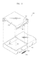
- the media cassette 400 includes a loading case 100 that receives media.
- a portion of an upper front edge portion of the loading case 100 is opened which forms an outlet 101 through which a pickup device (reference numeral 5 in Figure 5) located in a printing apparatus (reference numeral 20 in Figure 5) accesses the media.
- Reference numeral 200 denotes a shutter (which may be called a lid).
- the shutter 200 is slidably fitted onto the loading case 100. Therefore, a pair of protrusions 102 are located on a side portion of the loading case 100, and a pair of slots 201, into which the protrusions 102 are inserted, are correspondingly located on a side portion of the shutter 200. An end portion 202 of each slot 201 is slanted.
- the shutter 200 when the media cassette 400 is separated from the printing apparatus 20 for carrying, for example, the shutter 200 is located at a first position so the shutter 200 covers the outlet 101. Therefore, the media placed in the loading case 100 does not escape through the outlet 101. In this position, the shutter 200 is located at the same height as that of the upper surface of the loading case 100.
- Figure 5 shows a state where the media cassette 400 is mounted in the printing apparatus 20.
- a user moves the shutter 200 to a second position which opens the outlet 101. The user does this by pushing the shutter 200 in direction A, as shown in Figure 5.
- the media cassette 400 is thus mounted in the printing apparatus 20.
- the media cassette further includes an elastic member 300 biasing the shutter 200 for closing the outlet 101, or, in other words, biasing in the second position.
- the elastic member 300 is a tension coil spring, having respective end portions connected to the shutter 200 and the loading case 100.
- the media cassette 400 is pushed towards the printing apparatus 20 for mounting therein.
- the shutter 200 is pushed in the opposite direction (direction B) by a side portion 21 of the printing apparatus 20. Since the end 202 of the slot 201 is slanted, the shutter 200 moves slightly upward as it continues to slide in direction B. When the outlet 101 is opened, the shutter 200 is located on upper portion of the loading case 100.
- the media cassette 400 is removed from the printing apparatus 20 by moving the media cassette 400 in direction B.
- the shutter 200 moves in direction A because of the elastic force of the elastic member 300, thus covering the outlet 101.
- the shutter 200 is opened when the media cassette 400 is mounted in the printing apparatus 20. Therefore, damage to either the media cassette 400 or the printing apparatus 20 caused when inserting the media cassette 400 into the printing apparatus 20, as with the known media cassette, is prevented.
- the media cassette 400 is removed from the printing apparatus 20 by being moved in direction B. If the media cassette 400 does not include the elastic member 300, the user will push the shutter 200 in direction A thus covering the outlet 101. However, if the elastic member 300 is included in the media cassette 400, as the media cassette 400 is removed from the printing apparatus 20, the shutter 200 moves in direction A due to the elastic force of the elastic member 300 thus covering the outlet 101. Therefore, the user does not need to close the shutter 200.
- the shutter 200 slides over the upper portion of the loading case 100, a rear surface of the shutter 200 is not exposed during opening the outlet 101.
- an aesthetic appearance of the media cassette 400 is maintained even when the outlet 101 is opened.
- the printed media when fed out of the printing apparatus 20 is stacked on the upper surface of the media cassette 400.
- the media cassette shown in Figure 6 is modified from that of Figure 3.
- the shutter 200 is located above the upper surface of the loading case 100 when the outlet 101 is closed (or covered).
- the slots 201 extend parallel to the sliding direction of the shutter 200 without the ends of the slots 201 slanting. Therefore, the shutter 200 is slid only in directions A and B and moves to the first and second positions.
- the loading case 100 includes a frame 110 having an open upper portion, and an upper cover 120 that covers the upper portion.
- the outlet 101 through which the pickup device 5 of the printing apparatus 20 accesses the printable media, is created because of a difference in lengths between the frame 110 and the upper cover 120.
- a coupling protrusion 113 is located on a side portion of the frame 110, and a corresponding coupling hole 121 is located in the upper cover 120.
- the protrusion 113 may be located on the upper cover 120, and the coupling hole 121 may be formed in the frame 110.
- the media is loaded by rotating the upper cover 120 away from the frame 110 as shown in Figure 8.
- the media is loaded into the frame 110 and the upper cover 120 is then rotated back towards the frame 110 to form the cassette 100.
- the coupling hole 121 is elongated as shown in Figure 7, so that rotating the upper cover 120 is not hindered.
- the shutter 200 is coupled to the upper cover 120.
- the shutter 200 includes a pair of slots 201 that extend in the sliding direction of the shutter 200 and have slanted end portions 202.
- a pair of protrusions 102 are located on the upper cover 120 and are inserted into the slots 201.
- the upper cover 120 rotates to open the upper portion of the frame 110 and allow the media to be placed in the loading case 100.
- the user locates the media cassette 400 in the printing apparatus 20.
- the shutter 200 is pushed in direction B as shown in Figure 9 which opens the outlet 101.
- the shutter 200 is opened during the mounting operation. If the elastic member 300 is present, the shutter 200 is elastically biased towards the closed direction for the outlet 101. In other words, is biased towards the first position.
- the shutter 200 moves to cover the outlet 101 because of the elastic force of the elastic member 300.
- the upper cover 120 is coupled to the frame 110 which has an opened upper surface (first surface) 109 forming the loading case 100.
- the outlet 101, through which the pickup device 5 of the printing apparatus 20 accesses the media, is formed by the difference between the lengths of the frame 110 and the upper cover 120.
- the coupling protrusion 113 is located on an inner side portion of the upper cover 120, and the coupling hole 121 is located in the frame 110.
- the coupling hole 121 is elongated.
- the shutter 200 is coupled to the upper cover 120, and rotates therewith.
- the shutter 200 of this embodiment is located on an upper portion of the upper cover 120 when the shutter 200 covers the outlet 101.
- a pair of slots 201 extend in the direction which the shutter 200 slides. These slots 201 and are located on the side portion of the shutter 200.
- a pair of corresponding protrusions 102, which are inserted into the slots 201, are located on the upper cover 120.
- the media cassette 400 further includes the elastic member 300 that biases the shutter 200 towards closing the outlet 101.
- the elastic member 300 of the present embodiment is preferably a compression coil spring.
- the media cassette 400 further includes a first locking unit 205 that locks the shutter 200 when the shutter 200 either covers the outlet 101 or opens the outlet 101.
- a first locking unit 205 that locks the shutter 200 when the shutter 200 either covers the outlet 101 or opens the outlet 101.
- Projections 203 are disposed on both ends 206, 207 of the slot 201, and the projection 203 is formed on an arm 204 which is elastically deformable.
- the user pushes the shutter 200 in direction B for opening the outlet 101.
- the shutter 200 is locked by the first locking unit 205 when the outlet 101 is opened.
- the media cassette 400 is then mounted in the printing apparatus 20. Also, after the media cassette is removed from the printing apparatus 20, the user pushes the shutter 200 in direction A to close the outlet 101.
- the shutter 200 is locked in the closed position by the first locking unit 205.
- the shutter 200 may be opened as the media cassette 400 is located in the printing apparatus 20.
- the shutter 200 is pushed by a front portion 22 of the printing apparatus 20 in direction B to open the outlet 101.
- the protrusion 102 pushes the projection 203, and the arm 204 is elastically retrieved. Consequently, the protrusion 102 reaches the end 206 of the slot 201.
- the projection 203 then blocks the protrusion 102 while the arm 204 returns to the original position. The shutter 200 is thus locked with the outlet 101 being open.
- the shutter 200 moves in direction B by the elastic force of the elastic member 300, and slides to the other end 207 of the slot 201.
- the protrusion 102 reaches the other end 207 of the slot 201, the shutter 200 is locked by the first locking unit 205.
- a media cassette 400b of the present embodiment further includes a tray 250 for collecting the printed media M discharged from the printing apparatus 20.
- tray 250 is upwardly inclined in the direction of discharge of the media M. This assists in stacking of the discharged media M.
- the tray 250 When the media cassette 400b is removed from the printing apparatus 20, the tray 250 is located in a third position folded on the upper cover 120 as shown in Figure 15. In addition, when the media cassette 400b is located in the printing apparatus 20, it preferable that the tray 250 is located at a fourth, upwardly inclined position.
- the tray 250 of the present embodiment is rotatably installed on the shutter 200, and rotates toward the third and fourth positions when the shutter 200 moves between the first and second positions. According to the above structure, portability of the media cassette 400b is improved, and it is convenient to use the media cassette 400b since the user does not need to move the tray 250.
- a slot 251 is formed in the longitudinal direction of the tray 250.
- a slant rib 122 is upwardly inclined in the direction of conveying media M and is disposed on the upper cover 120.
- the slant rib 122 is inserted into the slot 251, thus the tray 250 is located at the third position.
- a second locking unit 260 locks the tray 250 in the third position.
- the second locking unit 260 includes a concave portion 123 located on one end of the slant rib 122 and a protruded portion 253 located on the slot 251.
- the tray 250 when the tray 250 is located in the third position, the protruded portion 253 is inserted in the concave portion 123, thus the tray 250 is not inclined.
- the shutter 200 when the shutter 200 is moved in direction A, to open the outlet 101, the protruded portion 253 is moved away from the concave portion 123 which unlocks the tray 250.
- the tray 250 When an end portion 252 of the slot 251 contacts the slant rib 122, the tray 250 is inclined.
- the tray 250 When the shutter 200 is located at the second position, the tray 250 is upwardly inclined in the fourth position. If the shutter 200 is moved in direction B in Figure 17 in order to close the outlet 101, the tray 250 is un-inclined and moves back toward the third position.
- the protruded portion 253 is reinserted into the concave portion 123, thus locking the tray 250 in the third position.
- an elastic piece 254 is located on slot 251, and a coupling recess 124, to which the elastic piece 254 is coupled, is located on the slant rib 122, as a modified example of the second locking unit 260.
- the elastic piece 254 engages the coupling recess 124 to lock the tray 250.
- the shutter 200 is moved to the second position, the elastic piece 254 falls out of the coupling recess 124, and the tray 250 is inclined towards the fourth position.
- the tray 250 and the second locking unit 260 can also be applied to the media cassettes shown in Figures 3 to 6.
- the slant rib 122 is disposed on the upper surface of the loading case 100.
- a frame 110a having an opened upper portion (first surface) 109 and an upper cover 120a covering the upper portion 109 of the frame 110a are disclosed.
- the upper cover 120a is coupled to the frame 110a and slides thereon.
- the upper cover 120a moves between the first position, where the upper portion 109 of the frame 110a is covered, and the second position, where the outlet 101 is formed by opening a part of the upper portion 109 of the frame 110a allowing the pickup device (reference numeral 5 in Figure 5) which is disposed on the printing apparatus (20 in Figure 5) to contact the media.
- a first slot 201a and a second slot 201b are located on a front edge and a rear end of the upper cover 120a, respectively.
- the first and second slots 201a, 201b are formed to be upwardly slanted from the front portion 208 towards the rear portion 209.
- a first protrusion 102a and a second protrusion 102b are respectively inserted into the first and second slots 201a, 201b, and are located on the side portion of the frame 110.
- the user can located the media cassette 400a in the printing apparatus (not shown) after opening the upper end portion of the frame 110a by pushing the upper covers 200a in direction B.
- the upper cover 120a may slide in direction B by contacting the printing apparatus.
- the upper cover 120a is slid while inclined, as shown in Figure 20.
- a stopper 130 is located on a front portion of the upper cover 120a.
- the printing apparatus discharges the printed medium onto the media cassette 400a.
- the discharged medium is stacked on the upper cover 120a.
- the stopper 130 protrudes from the upper cover 120a.
- the discharged medium slides toward the printing apparatus along the slanted upper cover 120a, and is stopped and arranged by the stopper 130.
- the discharged medium does not re-enter the printing apparatus 20.
- the front edge portion 208 of the first slot 201a is open.
- the first and second protrusions 102a, 102b are located at the front edge portions 208 of the first and second slots 201a and 201b, respectively. Accordingly, a rear end portion of the upper cover 120a is pushed in direction D of Figure 20.
- the first protrusion 102a escapes from the first slot 201 a through the front portion 208 of the open first slot 201 a, and the upper cover 120a is inclined as shown by the dotted line of Figure 20. This is because the uppercover 120a is rotating around the second protrusion 102b. According to the above operation, the upper cover 120a is rotated to open the upper portion of the frame 110a and allow the media to be located.
- the outlet is opened by mounting the media cassette in the printing apparatus, thus the user can use the media cassette more conveniently.
- the outlet can be closed automatically by the elastic force when the media cassette is removed from the printing apparatus.
- the aesthetic quality of the media cassette can be maintained.
- the printed media can be stacked on the media cassette.
- the tray that is moved to the position for being portable and the position for loading the media with the moving operation of the shutter is further included, therefore the convenience of the user is improved.
Abstract
Description
- The present invention relates to a cassette for storing printable media.
- A known portable printing apparatus such as a small photo quality-printer has a portable media cassette for storing media. The portable media cassette, into which printable media is placed, is typically detachable from the printing apparatus. The portable media cassette is manufactured so that the printing media will not escape from the cassette when the cassette is separated from the printing apparatus.
- Figure 1 is a cross-sectional view showing an example of a known portable media cassette. As shown in Figure 1, media M is placed in a loading case 1, and a
cover 4 is coupled to an upper portion of the loading case 1. Thecover 4 is divided into a first cover 2 and asecond cover 3. The first cover 2 is rotatably coupled to thesecond cover 3. When themedia cassette 10 is separated from the printing apparatus, the second cover 2 is closed so that the media M does not escape from themedia cassette 10. As shown in Figure 2, when themedia cassette 10 is connected to theprinting apparatus 20, the second cover 2 rotates to open a front edge portion of the loading case 1. This allows a pickup roller 5 to access and pick up the media M. However, since the second cover 2 is open when connected to theprinting apparatus 20, themedia cassette 10 can be easily damaged. - Additionally, when the known
media cassette 10 is mounted in theprinting apparatus 20, a back surface of the second cover 2 is exposed outside of theprinting apparatus 20 as shown in Figure 2. A printable medium is then discharged from themedia cassette 10. However, the second cover 2 is generally manufactured by a plastic injection moulding method. Therefore, the back surface includes a structure such as a strengthening rib or an ejection pin mark from the mould. This reduces the usefulness of themedia cassette 10. For example, as theprinting apparatus 20 has a media conveying path in the shape of a 'U', the strengthening rib or the ejection pin mark may interrupt the smooth discharging operation of the printed media from theprinting apparatus 20. - Accordingly, there is a need for an improved media cassette manufactured so that it will not be damaged when installed into the printing apparatus and is more useful, for example, by not interrupting conveying of the media.
- Further, there is a need for a media cassette that allows printed media discharged by a printing apparatus to be stored thereon.
- The present invention relates to a cassette for storing printable media.
- A cassette according to the present invention is characterised by a slidable member operable to provide an egress for media stored in the cassette
- Additional optional and/or preferred features are set forth in
claims 21 to 26 appended hereto. - An embodiment of the present invention will now be described, by way of example only, and with reference to Figures 3 to 20 of the following drawings, in which:
- Figure 1 is a cross-sectional view showing a known media cassette;
- Figure 2 is a cross-sectional view showing a state where a second cover is opened in the known media cassette shown in Figure 1;
- Figure 3 is an exploded perspective view showing a media cassette according to a first embodiment of the present invention;
- Figure 4 is a side view showing the media cassette of Figure 3;
- Figure 5 is a side view illustrating operations of the media cassette of Figure 3;
- Figure 6 is a side view showing a media cassette according to a second embodiment of the present invention;
- Figure 7 is an exploded perspective view showing a media cassette according to a third embodiment of the present invention;
- Figure 8 is a perspective view showing a state where an upper cover of the media cassette is rotated;
- Figure 9 is a perspective view showing a state where the media cassette according to the third embodiment of the present invention of Figure 7 is mounted in a printing apparatus;
- Figure 10 is a perspective view showing a media cassette according to a fourth embodiment of the present invention;
- Figure 11 is a perspective view showing part C of Figure 10 in detail;
- Figure 12 is a perspective view showing the media cassette according to the fourth embodiment of the present invention;
- Figure 13 is a perspective view showing a state where the media cassette shown in Figures 10 to 12 according to the fourth embodiment of the present invention is mounted in a printing apparatus;
- Figure 14 is a perspective view showing a media cassette according to a fifth embodiment of the present invention mounted in a printing apparatus;
- Figure 15 is a perspective view showing the media cassette according to the fifth embodiment of the present invention separated from the printing apparatus;
- Figures 16 and 17 are cross-sectional views showing operations of the media cassette according to the fifth embodiment of the present invention;
- Figure 18 is an exploded perspective view showing a modified example of a second locking unit; and
- Figures 19 and 20 are perspective views showing a media cassette according to a sixth embodiment of the present invention.
-
- Throughout the drawings, the same drawing reference numerals will be understood to refer to the same elements, features, and structures. Descriptions of well-known functions or constructions are omitted for conciseness.
- Referring to Figures 3 and 4, the
media cassette 400 includes aloading case 100 that receives media. A portion of an upper front edge portion of theloading case 100 is opened which forms anoutlet 101 through which a pickup device (reference numeral 5 in Figure 5) located in a printing apparatus (reference numeral 20 in Figure 5) accesses the media.Reference numeral 200 denotes a shutter (which may be called a lid). Theshutter 200 is slidably fitted onto theloading case 100. Therefore, a pair ofprotrusions 102 are located on a side portion of theloading case 100, and a pair ofslots 201, into which theprotrusions 102 are inserted, are correspondingly located on a side portion of theshutter 200. Anend portion 202 of eachslot 201 is slanted. - As shown in Figure 4, when the
media cassette 400 is separated from theprinting apparatus 20 for carrying, for example, theshutter 200 is located at a first position so theshutter 200 covers theoutlet 101. Therefore, the media placed in theloading case 100 does not escape through theoutlet 101. In this position, theshutter 200 is located at the same height as that of the upper surface of theloading case 100. - Figure 5 shows a state where the
media cassette 400 is mounted in theprinting apparatus 20. A user moves theshutter 200 to a second position which opens theoutlet 101. The user does this by pushing theshutter 200 in direction A, as shown in Figure 5. Themedia cassette 400 is thus mounted in theprinting apparatus 20. - As shown in Figures 3 and 4, the media cassette further includes an
elastic member 300 biasing theshutter 200 for closing theoutlet 101, or, in other words, biasing in the second position. Theelastic member 300 is a tension coil spring, having respective end portions connected to theshutter 200 and theloading case 100. - As shown in Figure 5, the
media cassette 400 is pushed towards theprinting apparatus 20 for mounting therein. However, as thecassette 400 is being mounted, theshutter 200 is pushed in the opposite direction (direction B) by aside portion 21 of theprinting apparatus 20. Since theend 202 of theslot 201 is slanted, theshutter 200 moves slightly upward as it continues to slide in direction B. When theoutlet 101 is opened, theshutter 200 is located on upper portion of theloading case 100. - The
media cassette 400 is removed from theprinting apparatus 20 by moving themedia cassette 400 in direction B. As thecassette 400 is moved in direction B, theshutter 200 moves in direction A because of the elastic force of theelastic member 300, thus covering theoutlet 101. - Accordingly, the
shutter 200 is opened when themedia cassette 400 is mounted in theprinting apparatus 20. Therefore, damage to either themedia cassette 400 or theprinting apparatus 20 caused when inserting themedia cassette 400 into theprinting apparatus 20, as with the known media cassette, is prevented. - The
media cassette 400 is removed from theprinting apparatus 20 by being moved in direction B. If themedia cassette 400 does not include theelastic member 300, the user will push theshutter 200 in direction A thus covering theoutlet 101. However, if theelastic member 300 is included in themedia cassette 400, as themedia cassette 400 is removed from theprinting apparatus 20, theshutter 200 moves in direction A due to the elastic force of theelastic member 300 thus covering theoutlet 101. Therefore, the user does not need to close theshutter 200. - Also, since the
shutter 200 slides over the upper portion of theloading case 100, a rear surface of theshutter 200 is not exposed during opening theoutlet 101. Thus, an aesthetic appearance of themedia cassette 400 is maintained even when theoutlet 101 is opened. In addition, there is no obstacle hindering the discharge of the medium from theprinting apparatus 20. Thus, the printed media, when fed out of theprinting apparatus 20 is stacked on the upper surface of themedia cassette 400. - Hereinafter, a media cassette according to other embodiments of the present invention will be described. Elements having the same functions as above are denoted by the same reference numerals and detailed descriptions of them are omitted.
- The media cassette shown in Figure 6 is modified from that of Figure 3. As denoted by the dotted line in Figure 6, the
shutter 200 is located above the upper surface of theloading case 100 when theoutlet 101 is closed (or covered). Theslots 201 extend parallel to the sliding direction of theshutter 200 without the ends of theslots 201 slanting. Therefore, theshutter 200 is slid only in directions A and B and moves to the first and second positions. - Referring to Figure 7, the
loading case 100 includes aframe 110 having an open upper portion, and anupper cover 120 that covers the upper portion. When theupper cover 120 is coupled to theframe 110, theoutlet 101, through which the pickup device 5 of theprinting apparatus 20 accesses the printable media, is created because of a difference in lengths between theframe 110 and theupper cover 120. Acoupling protrusion 113 is located on a side portion of theframe 110, and acorresponding coupling hole 121 is located in theupper cover 120. Alternatively, theprotrusion 113 may be located on theupper cover 120, and thecoupling hole 121 may be formed in theframe 110. - In the media cassette having the above structure, the media is loaded by rotating the
upper cover 120 away from theframe 110 as shown in Figure 8. The media is loaded into theframe 110 and theupper cover 120 is then rotated back towards theframe 110 to form thecassette 100. Here, it is desirable that thecoupling hole 121 is elongated as shown in Figure 7, so that rotating theupper cover 120 is not hindered. - As shown in Figure 8, in order to completely open the upper portion of the
frame 110 when theupper cover 120 is rotated, it is preferable that theshutter 200 is coupled to theupper cover 120. Theshutter 200 includes a pair ofslots 201 that extend in the sliding direction of theshutter 200 and have slantedend portions 202. A pair ofprotrusions 102 are located on theupper cover 120 and are inserted into theslots 201. - In the above media cassette, the
upper cover 120 rotates to open the upper portion of theframe 110 and allow the media to be placed in theloading case 100. The user locates themedia cassette 400 in theprinting apparatus 20. As themedia cassette 400 is located, theshutter 200 is pushed in direction B as shown in Figure 9 which opens theoutlet 101. In addition, as shown in Figure 9, when themedia cassette 400 is mounted in theprinting apparatus 20, theshutter 200 is opened during the mounting operation. If theelastic member 300 is present, theshutter 200 is elastically biased towards the closed direction for theoutlet 101. In other words, is biased towards the first position. Also, when themedia cassette 400 is removed from theprinting apparatus 20, theshutter 200 moves to cover theoutlet 101 because of the elastic force of theelastic member 300. - Referring to Figures 10 to 13, the
upper cover 120 is coupled to theframe 110 which has an opened upper surface (first surface) 109 forming theloading case 100. Theoutlet 101, through which the pickup device 5 of theprinting apparatus 20 accesses the media, is formed by the difference between the lengths of theframe 110 and theupper cover 120. Thecoupling protrusion 113 is located on an inner side portion of theupper cover 120, and thecoupling hole 121 is located in theframe 110. Preferably, thecoupling hole 121 is elongated. - The
shutter 200 is coupled to theupper cover 120, and rotates therewith. Theshutter 200 of this embodiment is located on an upper portion of theupper cover 120 when theshutter 200 covers theoutlet 101. A pair ofslots 201 extend in the direction which theshutter 200 slides. Theseslots 201 and are located on the side portion of theshutter 200. A pair of correspondingprotrusions 102, which are inserted into theslots 201, are located on theupper cover 120. Themedia cassette 400 further includes theelastic member 300 that biases theshutter 200 towards closing theoutlet 101. Theelastic member 300 of the present embodiment is preferably a compression coil spring. - The
media cassette 400 further includes afirst locking unit 205 that locks theshutter 200 when theshutter 200 either covers theoutlet 101 or opens theoutlet 101. Referring to Figure 11, an example of thefirst locking unit 205 is disclosed.Projections 203 are disposed on both ends 206, 207 of theslot 201, and theprojection 203 is formed on anarm 204 which is elastically deformable. - The user pushes the
shutter 200 in direction B for opening theoutlet 101. Theshutter 200 is locked by thefirst locking unit 205 when theoutlet 101 is opened. Themedia cassette 400 is then mounted in theprinting apparatus 20. Also, after the media cassette is removed from theprinting apparatus 20, the user pushes theshutter 200 in direction A to close theoutlet 101. Theshutter 200 is locked in the closed position by thefirst locking unit 205. - Also, the
shutter 200 may be opened as themedia cassette 400 is located in theprinting apparatus 20. When themedia cassette 400 is pushed in direction A for mounting in theprinting apparatus 20, theshutter 200 is pushed by afront portion 22 of theprinting apparatus 20 in direction B to open theoutlet 101. When themedia cassette 400 is mounted, theprotrusion 102 pushes theprojection 203, and thearm 204 is elastically retrieved. Consequently, theprotrusion 102 reaches theend 206 of theslot 201. Theprojection 203 then blocks theprotrusion 102 while thearm 204 returns to the original position. Theshutter 200 is thus locked with theoutlet 101 being open. - When the
media cassette 400 is removed from theprinting apparatus 20, theshutter 200 moves in direction B by the elastic force of theelastic member 300, and slides to theother end 207 of theslot 201. When theprotrusion 102 reaches theother end 207 of theslot 201, theshutter 200 is locked by thefirst locking unit 205. - Referring to Figure 14 and 15, a
media cassette 400b of the present embodiment further includes atray 250 for collecting the printed media M discharged from theprinting apparatus 20. Preferably,tray 250 is upwardly inclined in the direction of discharge of the media M. This assists in stacking of the discharged media M. - When the
media cassette 400b is removed from theprinting apparatus 20, thetray 250 is located in a third position folded on theupper cover 120 as shown in Figure 15. In addition, when themedia cassette 400b is located in theprinting apparatus 20, it preferable that thetray 250 is located at a fourth, upwardly inclined position. Thus, thetray 250 of the present embodiment is rotatably installed on theshutter 200, and rotates toward the third and fourth positions when theshutter 200 moves between the first and second positions. According to the above structure, portability of themedia cassette 400b is improved, and it is convenient to use themedia cassette 400b since the user does not need to move thetray 250. - Referring to Figure 16, a
slot 251 is formed in the longitudinal direction of thetray 250. Aslant rib 122 is upwardly inclined in the direction of conveying media M and is disposed on theupper cover 120. When theshutter 200 is located at the first position, theslant rib 122 is inserted into theslot 251, thus thetray 250 is located at the third position. Asecond locking unit 260 locks thetray 250 in the third position. Thesecond locking unit 260 includes aconcave portion 123 located on one end of theslant rib 122 and a protrudedportion 253 located on theslot 251. - As shown in Figure 16, when the
tray 250 is located in the third position, the protrudedportion 253 is inserted in theconcave portion 123, thus thetray 250 is not inclined. As shown in Figure 17, when theshutter 200 is moved in direction A, to open theoutlet 101, the protrudedportion 253 is moved away from theconcave portion 123 which unlocks thetray 250. When anend portion 252 of theslot 251 contacts theslant rib 122, thetray 250 is inclined. When theshutter 200 is located at the second position, thetray 250 is upwardly inclined in the fourth position. If theshutter 200 is moved in direction B in Figure 17 in order to close theoutlet 101, thetray 250 is un-inclined and moves back toward the third position. In addition, as theshutter 200 returns to the first position, the protrudedportion 253 is reinserted into theconcave portion 123, thus locking thetray 250 in the third position. - As shown in Figure 18, an
elastic piece 254 is located onslot 251, and acoupling recess 124, to which theelastic piece 254 is coupled, is located on theslant rib 122, as a modified example of thesecond locking unit 260. In the above structure, when thetray 250 is located at the third position, theelastic piece 254 engages thecoupling recess 124 to lock thetray 250. When theshutter 200 is moved to the second position, theelastic piece 254 falls out of thecoupling recess 124, and thetray 250 is inclined towards the fourth position. - The
tray 250 and thesecond locking unit 260 can also be applied to the media cassettes shown in Figures 3 to 6. In this case, theslant rib 122 is disposed on the upper surface of theloading case 100. - Referring to Figures 19 and 20, a
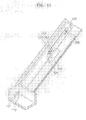
frame 110a having an opened upper portion (first surface) 109 and anupper cover 120a covering theupper portion 109 of theframe 110a are disclosed. Theupper cover 120a is coupled to theframe 110a and slides thereon. Theupper cover 120a moves between the first position, where theupper portion 109 of theframe 110a is covered, and the second position, where theoutlet 101 is formed by opening a part of theupper portion 109 of theframe 110a allowing the pickup device (reference numeral 5 in Figure 5) which is disposed on the printing apparatus (20 in Figure 5) to contact the media. Afirst slot 201a and a second slot 201b are located on a front edge and a rear end of theupper cover 120a, respectively. The first andsecond slots 201a, 201b are formed to be upwardly slanted from thefront portion 208 towards therear portion 209. Afirst protrusion 102a and asecond protrusion 102b are respectively inserted into the first andsecond slots 201a, 201b, and are located on the side portion of theframe 110. - According to the above structure, the user can located the
media cassette 400a in the printing apparatus (not shown) after opening the upper end portion of theframe 110a by pushing the upper covers 200a in direction B. - Also, when the
media cassette 400a is pushed in direction A to be mounted in the printing apparatus (not shown), theupper cover 120a may slide in direction B by contacting the printing apparatus. Here, theupper cover 120a is slid while inclined, as shown in Figure 20. When themedia cassette 400a is fully mounted in the printing apparatus, theoutlet 101, through which the pickup device (5 in Figure 5) of the printing apparatus (20 in Figure 5) accesses the media, is formed. - A
stopper 130 is located on a front portion of theupper cover 120a. The printing apparatus discharges the printed medium onto themedia cassette 400a. Here, the discharged medium is stacked on theupper cover 120a. Thestopper 130 protrudes from theupper cover 120a. The discharged medium slides toward the printing apparatus along the slantedupper cover 120a, and is stopped and arranged by thestopper 130. Thus, the discharged medium does not re-enter theprinting apparatus 20. - The
front edge portion 208 of thefirst slot 201a is open. When theupper cover 120a is pushed in the direction B, the first andsecond protrusions front edge portions 208 of the first andsecond slots 201a and 201b, respectively. Accordingly, a rear end portion of theupper cover 120a is pushed in direction D of Figure 20. Thefirst protrusion 102a escapes from thefirst slot 201 a through thefront portion 208 of the openfirst slot 201 a, and theupper cover 120a is inclined as shown by the dotted line of Figure 20. This is because theuppercover 120a is rotating around thesecond protrusion 102b. According to the above operation, theupper cover 120a is rotated to open the upper portion of theframe 110a and allow the media to be located. - According to the media cassette for the printing apparatus of embodiments of the present invention, the outlet is opened by mounting the media cassette in the printing apparatus, thus the user can use the media cassette more conveniently.
- When the elastic member is further included in the media cassette, the outlet can be closed automatically by the elastic force when the media cassette is removed from the printing apparatus.
- In addition, as the rear surface of the shutter is not exposed during opening/closing of the outlet, the aesthetic quality of the media cassette can be maintained. Also, the printed media can be stacked on the media cassette.
- The tray that is moved to the position for being portable and the position for loading the media with the moving operation of the shutter is further included, therefore the convenience of the user is improved.
Claims (26)
- A portable media cassette that is attachable to a printing apparatus, the media cassette comprising:a loading case for receiving media, the loading case having an outlet through which a pickup device disposed on the printing apparatus accesses the media; anda shutter installed on the loading case, the shutter being movable between a first position for covering the outlet and a second position for opening the outlet.
- The media cassette of claim 1, wherein the shutter is adapted to slide by contacting the printing apparatus..
- The media cassette of claim 2, further comprising:an elastic member for biasing the shutter in the direction of the second position.
- The media cassette of claim 1, further comprising:a tray for loading the media discharged from the printing apparatus, the tray installed on the shutter.
- The media cassette of claim 4, wherein the tray is rotated to a third position wherein the tray is folded on the loading case, and a fourth position wherein the tray is inclined with respect to the loading case for loading the media in accordance with moving the shutter between the first and second positions.
- The media cassette of claim 5, further comprising
a second locking unit for locking the tray in the third position. - The media cassette of one of claims 1 to 6, wherein the loading case includes:wherein the shutter is installed for slidable movement on the upper cover.a frame for receiving the media having an opened first surface; andan upper cover for covering the first surface of the frame. except the outlet is coupled to the frame,
- The media cassette of claim 7, further comprising:a slot extending in the sliding direction of the shutter and disposed on one of the shutter and the upper cover, and a protrusion adapted for insertion into the slot is disposed on the other one of the shutter and the upper cover.
- The media cassette of claim 8, wherein an end portion of the slot is slanted, and the shutter being located at the same height as the upper cover at the first position, and slidable over the upper cover for being moved to the second position.
- The media cassette of claim 8, wherein the shutter is located at higher position than the upper cover, and the slot is formed substantially parallel to the sliding direction of the shutter.
- The media cassette of claim 7, further comprising:a first locking unit for locking the shutter in the first and second positions.
- The media cassette of claim 7, wherein the upper cover is rotatably coupled to the frame for opening the first surface of the frame and loading the media in the frame.
- The media cassette of claim 7, further comprising:a tray on which the media discharged from the printing apparatus is loaded and installed on the shutter.
- The media cassette of claim 13, wherein the tray is rotated to a third position wherein the tray is folded on the loading case and a fourth position wherein the tray is inclined with respect to the loading case for loading the media in accordance with moving the shutter between the first and second positions.
- The media cassette of claim 14, further comprising
a second locking unit that locks the tray in the third position. - A portable media cassette that is attachable to a printing apparatus, the media cassette comprising:wherein when the upper cover is located at the second position, the upper cover is upwardly slanted from the front portion of the frame to a rear portion of the frame for loading the media discharged from the printing apparatus on the upper cover, and a stopper protrudes from the upper edge portion of the upper cover for arranging the discharged media.a frame for receiving media and having an opened first surface; and an upper cover coupled to the frame for slidable movement between a first position wherein the first surface is covered and a second position wherein an outlet is formed by opening a part of the first surface, so that a pickup device disposed on the printing apparatus can access the media,
- The media cassette of claim 16, wherein the upper cover interferes with the printing apparatus and moves to the second position when the media cassette is mounted in the printing apparatus.
- The media cassette of claim 16, wherein the upper cover is rotated for opening substantially the entire first surface of the frame when the upper cover is located at the second position.
- The media cassette of claim 18, wherein first and second slots are upwardly slanted and are disposed on front and rear edges of the frame and the upper cover, and first and second protrusions are inserted into the first and second slots, respectively, and an end portion of the first slot is open for rotation about the second protrusion when the upper cover is located at the second position.
- A cassette (400, 400a, 400b) for storing printable media, characterised by a slidable member (200) operable to provide an egress for media stored in the cassette (400, 400a, 400b).
- A cassette (400, 400a, 400b) according to claim 20, wherein the slidable member (200) is retractable.
- A cassette (400b) according to either one of claims 20 or 21, comprising a media receiving means (250), located on the slidable member (200), configured to receive media.
- A cassette (400b) according to claim 22, comprising means (122) operable to displace one edge of said media receiving means (250) away from media stored in the cassette (400b).
- A cassette (400b) according to either one of claim 22 or 23, comprising means for preventing displacement of said media receiving means away from said media, when said slidable member is in its closed configuration.
- A printing apparatus comprising a cassette mounting means configured such that operatively mounting a cassette (400, 400a, 400b), according to any one of claims 20 to 24, thereto effects opening of the slidable member of the cassette being mounted.
- A printing apparatus according to claim 25, comprising a cassette (400, 400a, 400b) according to any one of claims 20 to 24 mounted by said cassette mounting means.
Applications Claiming Priority (6)
| Application Number | Priority Date | Filing Date | Title |
|---|---|---|---|
| KR20040004430 | 2004-01-20 | ||
| KR2004004430 | 2004-01-20 | ||
| KR20040024025 | 2004-04-08 | ||
| KR2004024025 | 2004-04-08 | ||
| KR2004064262 | 2004-08-16 | ||
| KR1020040064262A KR100636159B1 (en) | 2004-01-20 | 2004-08-16 | Media cassette of printer |
Publications (2)
| Publication Number | Publication Date |
|---|---|
| EP1557384A2 true EP1557384A2 (en) | 2005-07-27 |
| EP1557384A3 EP1557384A3 (en) | 2008-08-27 |
Family
ID=34636997
Family Applications (1)
| Application Number | Title | Priority Date | Filing Date |
|---|---|---|---|
| EP05100317A Withdrawn EP1557384A3 (en) | 2004-01-20 | 2005-01-19 | A printable media cassette |
Country Status (3)
| Country | Link |
|---|---|
| US (1) | US7322763B2 (en) |
| EP (1) | EP1557384A3 (en) |
| CN (1) | CN100348425C (en) |
Families Citing this family (21)
| Publication number | Priority date | Publication date | Assignee | Title |
|---|---|---|---|---|
| JP3807624B2 (en) * | 2004-04-13 | 2006-08-09 | 船井電機株式会社 | Paper cassette for image forming apparatus |
| JP4612883B2 (en) * | 2004-10-28 | 2011-01-12 | キヤノン株式会社 | Image forming apparatus |
| JP4545575B2 (en) * | 2004-12-14 | 2010-09-15 | ローレル機械株式会社 | Bill take-in device |
| JP4449809B2 (en) * | 2005-04-01 | 2010-04-14 | 船井電機株式会社 | Image forming apparatus |
| JP4585946B2 (en) * | 2005-05-18 | 2010-11-24 | キヤノン株式会社 | Sheet feeding apparatus and image forming apparatus |
| KR100726433B1 (en) * | 2005-11-25 | 2007-06-11 | 삼성전자주식회사 | Media cassette |
| JP2008007311A (en) * | 2006-06-30 | 2008-01-17 | Brother Ind Ltd | Image recording device |
| KR101305511B1 (en) * | 2006-07-25 | 2013-09-05 | 삼성전자주식회사 | Mobile image forming apparatus |
| TWI314513B (en) * | 2006-11-23 | 2009-09-11 | Lite On Technology Corp | Processing device having a cover capable of moving straight for covering at least a portion of a surface of an object sticking out of a main body |
| US8047534B2 (en) * | 2008-02-29 | 2011-11-01 | Brother Kogyo Kabushiki Kaisha | Sheet accommodating device and image recording apparatus with a translating pressing member attached to a rotating tray cover |
| CN101655675B (en) * | 2008-08-20 | 2011-05-25 | 山东新北洋信息技术股份有限公司 | Upper cover opening and closing mechanism and recording medium processing device using mechanism |
| JP5696839B2 (en) * | 2011-02-01 | 2015-04-08 | セイコーエプソン株式会社 | Recording device |
| JP5768535B2 (en) * | 2011-06-29 | 2015-08-26 | 株式会社リコー | Image forming apparatus |
| US9278553B2 (en) * | 2012-02-28 | 2016-03-08 | Seiko Epson Corporation | Recording apparatus with medium receiving tray having recess for storing feeding unit |
| JP5994479B2 (en) * | 2012-08-22 | 2016-09-21 | セイコーエプソン株式会社 | Recording medium cassette and recording device |
| JP5955182B2 (en) * | 2012-09-26 | 2016-07-20 | キヤノン株式会社 | Paper cassette and printing device |
| JP6046101B2 (en) * | 2014-11-21 | 2016-12-14 | 京セラドキュメントソリューションズ株式会社 | Sheet cassette and image forming apparatus having the same |
| JP6800619B2 (en) * | 2016-06-03 | 2020-12-16 | キヤノン株式会社 | Sheet feeding device and image forming device |
| JP6806477B2 (en) | 2016-07-19 | 2021-01-06 | キヤノン株式会社 | A sheet loading device and an image forming device including the sheet loading device. |
| US20190329997A1 (en) * | 2018-04-30 | 2019-10-31 | Hewlett-Packard Development Company, L.P. | Tray cover |
| JP7371068B2 (en) * | 2021-08-18 | 2023-10-30 | キヤノン株式会社 | Cassette and recording device |
Citations (6)
| Publication number | Priority date | Publication date | Assignee | Title |
|---|---|---|---|---|
| JPS59167427A (en) * | 1983-03-14 | 1984-09-20 | Fuji Xerox Co Ltd | Paper feed cassette for copying machine |
| JPH0664761A (en) * | 1992-08-12 | 1994-03-08 | Nikon Corp | Paper cassette |
| JPH09269586A (en) * | 1996-03-29 | 1997-10-14 | Konica Corp | Method and device for supplying sheet film |
| JP2000289863A (en) * | 1999-04-06 | 2000-10-17 | Matsushita Graphic Communication Systems Inc | Recording device and paper feeding cassette |
| JP2001253556A (en) * | 2000-03-14 | 2001-09-18 | Olympus Optical Co Ltd | Printing paper sheet storing cassette |
| US6412772B1 (en) * | 1998-08-04 | 2002-07-02 | Matsushita Graphic Communication Systems, Inc. | Container for recording medium |
Family Cites Families (16)
| Publication number | Priority date | Publication date | Assignee | Title |
|---|---|---|---|---|
| JPS6087482A (en) | 1983-10-20 | 1985-05-17 | Matsushita Electric Ind Co Ltd | Cassette with cover |
| US4698646A (en) * | 1984-09-14 | 1987-10-06 | Nippon Kogaku K. K. | Thermal transfer recording system |
| US5053814A (en) * | 1986-12-24 | 1991-10-01 | Minolta Camera Kabushiki Kaisha | Image forming apparatus |
| JPH0616766Y2 (en) * | 1987-12-25 | 1994-05-02 | シチズン時計株式会社 | Printer top cover |
| JPH0717077B2 (en) * | 1989-09-04 | 1995-03-01 | 三菱電機株式会社 | Paper feed / discharge path structure |
| US5120040A (en) * | 1989-11-09 | 1992-06-09 | Dataproducts | Sheet media tray and mechanism for feeding media of two different sizes |
| JPH04100133U (en) * | 1991-02-08 | 1992-08-28 | ||
| JPH05242637A (en) * | 1992-02-27 | 1993-09-21 | Sony Corp | Tape cassette |
| JPH0820448A (en) | 1994-07-07 | 1996-01-23 | Casio Electron Mfg Co Ltd | Paper feed cassette |
| JPH11213513A (en) * | 1998-01-26 | 1999-08-06 | Teac Corp | Recording medium loading device |
| JP2000085983A (en) * | 1998-09-10 | 2000-03-28 | Sharp Corp | Printing device |
| JP2000247456A (en) | 1999-02-25 | 2000-09-12 | Murata Mach Ltd | Paper feeding cassette device |
| US6106178A (en) * | 1999-04-12 | 2000-08-22 | Hewlett-Packard Company | Printer and printer paper tray |
| US6340256B1 (en) * | 2000-01-05 | 2002-01-22 | Hewlett-Packard Company | Media channel and method of clearing media jams |
| JP2002068535A (en) | 2000-08-31 | 2002-03-08 | Seiko Epson Corp | Manually feeding/delivery tray, sheet feeding cassette and recorder |
| KR100431006B1 (en) * | 2002-05-10 | 2004-05-12 | 삼성전자주식회사 | Paper cartridge for printer |
-
2005
- 2005-01-18 CN CNB2005100047028A patent/CN100348425C/en not_active Expired - Fee Related
- 2005-01-18 US US11/036,070 patent/US7322763B2/en not_active Expired - Fee Related
- 2005-01-19 EP EP05100317A patent/EP1557384A3/en not_active Withdrawn
Patent Citations (6)
| Publication number | Priority date | Publication date | Assignee | Title |
|---|---|---|---|---|
| JPS59167427A (en) * | 1983-03-14 | 1984-09-20 | Fuji Xerox Co Ltd | Paper feed cassette for copying machine |
| JPH0664761A (en) * | 1992-08-12 | 1994-03-08 | Nikon Corp | Paper cassette |
| JPH09269586A (en) * | 1996-03-29 | 1997-10-14 | Konica Corp | Method and device for supplying sheet film |
| US6412772B1 (en) * | 1998-08-04 | 2002-07-02 | Matsushita Graphic Communication Systems, Inc. | Container for recording medium |
| JP2000289863A (en) * | 1999-04-06 | 2000-10-17 | Matsushita Graphic Communication Systems Inc | Recording device and paper feeding cassette |
| JP2001253556A (en) * | 2000-03-14 | 2001-09-18 | Olympus Optical Co Ltd | Printing paper sheet storing cassette |
Also Published As
| Publication number | Publication date |
|---|---|
| EP1557384A3 (en) | 2008-08-27 |
| CN100348425C (en) | 2007-11-14 |
| US7322763B2 (en) | 2008-01-29 |
| US20050158111A1 (en) | 2005-07-21 |
| CN1644389A (en) | 2005-07-27 |
Similar Documents
| Publication | Publication Date | Title |
|---|---|---|
| EP1557384A2 (en) | A printable media cassette | |
| KR100906167B1 (en) | Lid opening and closing device | |
| US6981586B2 (en) | Magnetic tape cassette storage case | |
| US5804332A (en) | Battery accommodating chamber structure | |
| EP1591259A2 (en) | A Printing Media Cassette | |
| KR101350659B1 (en) | A business card case | |
| US6952545B2 (en) | OPC unit exchanging apparatus | |
| WO2011067981A1 (en) | Card holder | |
| EP1246188A2 (en) | Cartridge for an information recording medium | |
| KR100453393B1 (en) | The recording / | |
| KR100636159B1 (en) | Media cassette of printer | |
| KR100727930B1 (en) | Media cassette of printer | |
| CN109573375B (en) | Container and locking device thereof | |
| EP0582206B1 (en) | Tape cartridge | |
| KR20050112302A (en) | Media cassette of printer | |
| EP0558323B1 (en) | Tape cassettes | |
| JP2003212358A (en) | Paper feeding tray for printer and ejected paper tray for printer | |
| JP3713861B2 (en) | Storage case for disc cartridge | |
| US6666397B2 (en) | Tape cassette and cassette holder | |
| JP2002236884A (en) | Card inserting part opening-closing mechanism of mobile device | |
| KR20210025644A (en) | Camera Accessories and Cameras | |
| JP3120231B2 (en) | Tape cartridge | |
| JP3755681B2 (en) | Storage case for disc cartridge | |
| JPS6331259Y2 (en) | ||
| JPH09110182A (en) | Automatic paper feed tray |
Legal Events
| Date | Code | Title | Description |
|---|---|---|---|
| PUAI | Public reference made under article 153(3) epc to a published international application that has entered the european phase |
Free format text: ORIGINAL CODE: 0009012 |
|
| AK | Designated contracting states |
Kind code of ref document: A2 Designated state(s): AT BE BG CH CY CZ DE DK EE ES FI FR GB GR HU IE IS IT LI LT LU MC NL PL PT RO SE SI SK TR |
|
| AX | Request for extension of the european patent |
Extension state: AL BA HR LV MK YU |
|
| PUAL | Search report despatched |
Free format text: ORIGINAL CODE: 0009013 |
|
| AK | Designated contracting states |
Kind code of ref document: A3 Designated state(s): AT BE BG CH CY CZ DE DK EE ES FI FR GB GR HU IE IS IT LI LT LU MC NL PL PT RO SE SI SK TR |
|
| AX | Request for extension of the european patent |
Extension state: AL BA HR LV MK YU |
|
| AKX | Designation fees paid | ||
| REG | Reference to a national code |
Ref country code: DE Ref legal event code: 8566 |
|
| STAA | Information on the status of an ep patent application or granted ep patent |
Free format text: STATUS: THE APPLICATION IS DEEMED TO BE WITHDRAWN |
|
| 18D | Application deemed to be withdrawn |
Effective date: 20090228 |