EP1559480A1 - Pipette with displacement mechanism detachably connected to actuating mechanism - Google Patents
Pipette with displacement mechanism detachably connected to actuating mechanism Download PDFInfo
- Publication number
- EP1559480A1 EP1559480A1 EP05000211A EP05000211A EP1559480A1 EP 1559480 A1 EP1559480 A1 EP 1559480A1 EP 05000211 A EP05000211 A EP 05000211A EP 05000211 A EP05000211 A EP 05000211A EP 1559480 A1 EP1559480 A1 EP 1559480A1
- Authority
- EP
- European Patent Office
- Prior art keywords
- drive
- displacement
- pipetting device
- pipetting
- displaceable
- Prior art date
- Legal status (The legal status is an assumption and is not a legal conclusion. Google has not performed a legal analysis and makes no representation as to the accuracy of the status listed.)
- Granted
Links
Images
Classifications
-
- B—PERFORMING OPERATIONS; TRANSPORTING
- B01—PHYSICAL OR CHEMICAL PROCESSES OR APPARATUS IN GENERAL
- B01L—CHEMICAL OR PHYSICAL LABORATORY APPARATUS FOR GENERAL USE
- B01L3/00—Containers or dishes for laboratory use, e.g. laboratory glassware; Droppers
- B01L3/02—Burettes; Pipettes
- B01L3/021—Pipettes, i.e. with only one conduit for withdrawing and redistributing liquids
- B01L3/0217—Pipettes, i.e. with only one conduit for withdrawing and redistributing liquids of the plunger pump type
-
- B—PERFORMING OPERATIONS; TRANSPORTING
- B01—PHYSICAL OR CHEMICAL PROCESSES OR APPARATUS IN GENERAL
- B01L—CHEMICAL OR PHYSICAL LABORATORY APPARATUS FOR GENERAL USE
- B01L13/00—Cleaning or rinsing apparatus
- B01L13/02—Cleaning or rinsing apparatus for receptacle or instruments
-
- B—PERFORMING OPERATIONS; TRANSPORTING
- B01—PHYSICAL OR CHEMICAL PROCESSES OR APPARATUS IN GENERAL
- B01L—CHEMICAL OR PHYSICAL LABORATORY APPARATUS FOR GENERAL USE
- B01L2200/00—Solutions for specific problems relating to chemical or physical laboratory apparatus
- B01L2200/02—Adapting objects or devices to another
- B01L2200/025—Align devices or objects to ensure defined positions relative to each other
Definitions
- the invention relates to a pipetting device with a displacement device and a drive means releasably connected thereto.
- Pipetting devices are used especially in the laboratory for dosing liquids used. These are taken up in pipette tips through a tip opening and spent.
- air cushion pipettes is a displacement device for a gas integrated into the pipetting device and communicating through the approach with the Pipette tip connected.
- the displacement device is an air cushion displaced so that liquid sucked into the pipette tip and ejected from it becomes.
- the displacement device is usually a cylinder with a movable therein Piston.
- Pipette tips are detachably connected to the neck to keep them in after use can be replaced with a fresh pipette tip. This can be at subsequent dosing contaminations are avoided.
- Pipette tips for the one-time use are available inexpensively from plastic.
- the approach for attaching pipette tips is often a cylindrical or conical projection with respect to a base body or a housing, on the one Pipette tip can be clamped with a matching push-on opening or receptacle is. This can be done without touching the pipette tip by pressing the projection into the Plug-in opening happen to be provided in a holder pipette tip.
- a discharge device with a drive device and an ejector.
- the ejector By Actuating the drive means, the ejector is displaced so that it the pipette tip from the approach solves, without this must be handled by the user.
- the drive device has a mechanism that by means of an actuating button must be manually operated to release the pipette tip from the approach.
- drive devices with an electric motor drive. The Loosening the pipette tip from the neck can require considerable effort especially with pipette tips clamped firmly on the neck.
- single-channel systems i.e.
- Pipetting devices that provide a single approach to a single Pipette tip, this may be the ejection of the pipette tip from the approach make it difficult or impossible.
- Particularly high expenditure of force can be achieved in multi-channel pipetting systems, the multiple parallel approaches for attaching pipette tips have to be required due to multiple peak ejection forces.
- EP 0 992 288 A2 is a pipetting system with an axially movable Ejector for releasing a pipette tip from a hub, drive means for driving the axial movements of the ejector and an axial drive movement the drive device transmit in an axial movement of the ejector Anlagenstoff-, pressure medium or linkage known. From the ejector to the Force applied by the pipette tip exceeds the force applied by the user, whereby the throwing off is facilitated.
- the invention is based on the object, a pipetting device to provide at the displacement device and drive means easier and faster connectable and separable from each other and at the Connection is less susceptible to interference.
- the displacement device and the drive device of the pipetting device are in a simple manner by mating along a longitudinal axis of the bayonet connection and rotating about the longitudinal axis of the bayonet connection with each other connectable or in opposite ways separable from each other.
- the invention enables a particularly simple, fast and safe connection and disconnection of the displacement device and the Drive device, for example, during assembly, before autoclaving or other cleaning of the lower part, before replacing the lower part for purposes change of work area, repair, etc.
- the bayonet connection is especially trouble-prone.
- the drive device can be designed in various ways. She has by technical means to displace the drive mechanism so that this is the displaceable one Displaced limitation of the displacement device.
- the drive organ e.g. a linear motion.
- the drive device has a Linear actuator on. These are e.g. one directly by pressing a button manually operated lift rod or one via an electric drive motor and a transmission linearly displaceable lifting rod. It also comes into consideration pneumatically or hydraulically operated pressure cylinder as drive for the Lifting rod, which has a pneumatic or hydraulic control and a Pressure medium reservoir is actuated. If the drive member no linear movement performs, but a spatial feed movement, the drive means a corresponding drive.
- the drive device has a housing, in the drive and Drive member are arranged.
- the drive member is a parallel to the longitudinal axis of the Bayonet connection displaceable lifting rod of the drive device and has the Displacement device connected to the boundary, transverse to the lifting rod directed contact surface, by a lifting spring against the end of the lifting rod is pressed.
- the operative connection between the drive member and movable limit automatically when making the bayonet connection made and automatically released when dissolving the bayonet connection.
- the contact surface is connected to a via a rod with the displaceable boundary connected pressure piece formed and is the lifting spring designed as a helical spring, which at one end on the pressure piece and the other at the Displacement chamber is supported.
- the bayonet connection can be configured in various ways. Involved by The invention is in particular the embodiment of the drive device as a male Part and the displacement device as a female part of the bayonet connection and vice versa.
- the drive device a cylindrical receptacle having at one end an opening through which the cylindrical receptacle in the axial direction is accessible from the outside, the at least having an axially directed longitudinal groove, with a circumferential direction of the cylindrical Receiving directional annular groove is connected, and has the displacement device on a cylindrical portion at least one outwardly projecting Projection, wherein the cylindrical portion in the axial direction of the cylindrical Recording through the opening in the receptacle and with the projection in the Longitudinal groove can be inserted and screwed with the projection in the annular groove.
- the drive means the female and the displacement device the male part.
- the annular groove at a distance from the longitudinal groove a in the axial direction of the recording extended boundary wall, up to the Projection is rotatable. The achievement of the limit indicates to the user that the Bayonet connection is made.
- the annular groove is at a distance from the longitudinal groove a parallel thereto extending L Lucassnutabexcellent connected in a Distance from the opening ends.
- the annular groove has a ramp-like boundary wall, their distance from the opening with increasing distance from the Longitudinal groove increases.
- the ramp-like course of the boundary wall facilitates the Finding the connection position and separating the displacement of the drive device.
- the longitudinal groove, the annular groove and optionally the L jossnutabrough formed in a cylindrical coupling piece, which is the receptacle of Drive device forms and is fixed in this. This will produce, Assembly and disassembly easier.
- the drive device on a spring which against the Displacement device connected to the drive device via the bayonet connection suppressed. This will secure the bayonet connection.
- the spring is at a further opening of the receptacle arranged, that of the opening for axial insertion of the displacement device opposite. Through the opening displacement and spring act on each other one.
- the spring is a helical spring which is supported on an inner end face of the coupling piece.
- the longitudinal groove and / or annular groove and / or the Leksnutabrough opened for further opening.
- the displacement device is a piston-cylinder device with a cylinder and a piston displaceable therein and has the Piston on the movable limit.
- Other displacement devices are also included by the invention, for example, a displacement chamber with an elastic wall forming the displaceable boundary.
- a piston-cylinder device is e.g. operated by a linear drive device.
- a corresponding actuation is in a displacement chamber with an elastic Wall possible.
- the latter can also be a drive device with a controlled spatial drive movement. So it is possible, for example, the elastic wall by action of a hydraulic or pneumatic Control pressure medium from the outside.
- the approach is coaxial with the longitudinal axis of the bayonet connection aligned. According to a further embodiment, the approach is fixed with connected to the displacement device.
- the pipetting device has a discharge device for Discard a pipette tip from the hub, the one at the drive device arranged discharge drive, one arranged on the displacement device Ejector and a directed in the direction of the longitudinal axis of the bayonet connection, having releasable axial clamping connection between the ejection drive and ejector.
- the Clamping is simultaneous with the manufacture of the bayonet connection with the Phase of the axial pushing together of displacing device and drive device can be produced and released in the opposite direction.
- the ejection drive one of the drive device parallel to the bayonet connection projecting discharge rod and the ejector a to Approach parallel, axial bore, with which the discharge rod is press-connected.
- the ejector is guided on the displacement device.
- the ejector is one on the displacement device guided sleeve.
- the pipetting device is a hand-held device and / or a stationary device and / or an electrically powered device and / or a (Semi) automatic.
- the pipetting device of Hand led to the location of the sample taking and sample deliveries and becomes the Pickup and delivery of liquid and the operation of the discharge device controlled by hand.
- the drive means for the displacement device and / or the ejector are designed mechanically and / or electromechanically. The latter also applies to the execution of the pipetting as a stationary device.
- the pipetting device When the pipetting device is designed as a (semi) automaton, all Functions or part of the functions of the pipetting devices (recording and Dispensing liquid, moving the pipetting devices into positions for Picking up and dispensing liquid or pipette tips, picking up and dispensing from pipette tips) automatically.
- the pipetting device has a number of parallel Approaches for receiving pipette tips.
- This is a Multichannel pipetting.
- Each batch of the pipetting device is a separate one Displacement device or a common assigned, via a bayonet connection is connected to the drive device. It can be a act common drive device for all displacement devices.
- top refers to the Orientation of the pipetting device according to the drawing. This is an orientation of the pipetting device, wherein the pipette tip with its tip opening is arranged down to liquid from a below the pipetting device take up or deliver in such a vessel.
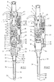
- the pipetting device according to FIGS. 1 and 2 has an elongated handle shaped Housing 1 with an upper housing part 2 and a lower housing part 3. Das Upper housing part 2 with all parts contained forms a drive device and the lower housing part 3 with all parts contained a displacement device.
- the upper housing part 2 has a screw top cover 4 at the top above an adjustment 5 out.
- the adjusting sleeve 5 is in the upper housing part 2 axially stored immovable and rotatable.
- a push button 6 is arranged, which still further upwards protrudes.
- the push button 6 is connected to a lifting rod 7, which in the upper housing part. 2 is passed through a spindle 8.
- the spindle 8 is in an internal thread 9 of a Screwed in the upper housing part 2 bearing body 10 is screwed.
- the spindle 8 has a rotatably connected to her driver 11 above.
- the Driver 11 has on the circumference two diametrically opposed radial projections 12.
- the radial projections 12 engage in - not shown - axially extending Grooves of the adjusting sleeve 5 a.
- the spindle 8 has at the bottom an end stop 13 in the form of radially outwardly projecting Ribs. In the position shown, the end stop 13 is a small piece below a shoulder 14 of the bearing body 10 with which it cooperates.
- the lifting rod 7 has a flange 15, which in the position shown at the bottom of the Spindle 8 is applied.
- a spring plate 16 is arranged, with a Collar 17 engages in the bearing body 10.
- the spring plate 16 has an axial bottom protruding, sleeve-shaped bearing portion 18 through which the lifting rod 7 passed is.
- the pipetting device on a spring, not shown, which the lifting rod 7 presses upward, so that the flange 15 at the bottom of the spindle. 8 is applied.
- a coil spring between flange 15 and spring plate 16th arranged.
- a coupling piece in the housing 19th attached at a distance below the spring plate 16 at a distance below the spring plate 16 at a distance below the spring plate 16 is a coupling piece in the housing 19th attached.
- This has several pockets inside 20. These have an axial over the Total length of the coupling piece 19 extended longitudinal groove 21. Furthermore, they have at the top End of the coupling piece 19 a over a small part of the circumference of the coupling piece 19 extended annular groove 22. This has at a distance from the upper end of the Coupling piece 19 below a ramp-like boundary wall, the starting from the longitudinal groove 21 increasingly to the upper end of the coupling piece 19th is approximated. Finally, the pockets 20 at the other end of the annular groove 22nd a short axial longitudinal groove portion 23 spaced at a distance from the upper end of the Coupling piece 19 ends in the coupling piece 19.
- spring 24 under bias arranged, which is designed as a helical spring.
- the adjusting sleeve 5 has on the circumference a sprocket 25 which is connected to a gear 26th cooperates, a counter 27 with several superimposed on an axis 28th arranged Zumblelwerkssonn 29 drives.
- the counter wheels 29 each have Numerals from 0 to 9, the lower Zählwerksrad 29 is driven by the gear 26.
- the arranged above it Zählwerksson 29 are further rotated by one digit, when the underlying Zählwerksrad 29 passes from 9 to 0.
- the lower housing part 3 can be detachably connected to the upper housing part 2. For this purpose points the lower housing part 3 on the jacket of an upper, cylindrical portion 30th a plurality of outwardly projecting projections or ribs 31, which extend in the axial direction of the cylindrical portion 30 extend.
- the lower housing part 3 has a plurality of below the cylindrical portion 30 conical sections 31 to 33 of different length and taper coming from the Drawing to emerge.
- the conical section 33 is down with a long, light conical projection 34 connected to attach a pipette tip. This one has turn down a short, more conical Aufsteckende 35.
- the lower housing part 3 houses a displacement device in the form of a Piston-cylinder unit 36. This has a arranged in the conical portion 32 Cylinder 37, in which a piston 38 dips. The piston 38 is above a piston rod 39 connected to a pressure piece 40. The piston 38 forms a displaceable Limitation of the cylinder 37.
- the lower housing part 3 has a piston holder 41, the the cylindrical portion 30 bridged above.
- the piston holder 41 has a top one central passage 42 through which a lower portion of the reciprocating piston 7 axially can be passed.
- a Lifting spring 43 arranged, which is designed as a helical spring. By the lifting spring 43 the piston 38 and the piston rod 39 are passed.
- the lifting spring 43 is biased and presses the pressure piece 40 against the piston holder 41, so that the piston 38 is pulled out of the cylinder 37 maximum.
- a connecting passage 44 passes through the boss 34 and connects the cylinder 37 with a muzzle in Aufsteckende 35.
- the pipetting device has a discharge device 45.
- the discharge device 45 has in the upper housing part 2 next to the knob 5, an operating button 46th
- the operating knob 46 is connected to a discharge rod 47 which is parallel to Lifting rod 7 passes through the upper housing part 2 therethrough.
- a transmission 48 is integrated in the discharge rod 47.
- the transmission 48 sets a axial actuating stroke of the actuating knob 46 in a smaller drive stroke with increased strength.
- Suitable transmissions 48 are described in EP 0 992 288 A, and Although generally in the general part of the description and especially in the figure description, which are incorporated by reference into the present application.
- the discharge rod 47 is connected via a further coil spring 49 in the upper housing part. 2 supported, so that the actuating button 46 is pressed into the starting position shown is in which he is pressed against the action of the other coil spring 49.
- the lower end of the discharge rod 47 protrudes into a receptacle 50 at the lower end of the Housing top 2 into it.
- the discharge device 45 has on the lower housing part 3 a discharge sleeve 51. This is on the cylindrical portion 30, the conical portion 32 and the projection 34th guided. Accordingly, the contour of the discharge sleeve 51 is the contours of the aforementioned Sections of the lower housing part 3 aligned.
- the ejection sleeve has 51 inside steps 52, 53, which limit the sliding of the discharge sleeve 51 upwards, by abutting against conical sections 31, 33 of the housing lower part 3.
- the pipetting device can be used as follows:
- the lifting rod engages 7 through the passage 42 through and lies with its lower end to the Pressure piece 40 on.
- a pipette tip 56 is clamped on the lower end of the projection 34.
- the pipette tip 56 has a lower tip opening 57 for receiving and dispensing of liquid.
- the push button 6 For pipetting the push button 6 is pressed down, so that the piston 38th Air displaced from the cylinder 37. Then the pipette tip 56 with its lower Tip opening 57 immersed in the liquid to be pipetted. After that, the Push button 6 released and the lifting rod 7 is under spring action in its starting position back. Similarly, the piston 38 returns under the action of the spring 43 in his starting position back. Here, the piston 38 sucks liquid through the lower tip opening 57 into the pipette tip 56.
- the lower tip opening 57 of the pipetting device becomes a discharge site aligned.
- the liquid contained in the pipette tip 56 is pressed in the push button 6, re-immersion of the piston 38 in the cylinder 37th and expelling air through the connecting channel 44 delivered. After releasing of the actuating knob 6 drive the lifting rod 7 and the piston 38 by spring force back to the starting position.
Abstract
Description
Die Erfindung bezieht sich auf eine Pipettiervorrichtung mit einer Verdrängungseinrichtung und einer damit lösbar verbundenen Antriebseinrichtung.The invention relates to a pipetting device with a displacement device and a drive means releasably connected thereto.
Pipettiervorrichtungen werden insbesondere im Labor zur Dosierung von Flüssigkeiten verwendet. Diese werden in Pipettenspitzen durch eine Spitzenöffnung aufgenommen und ausgegeben. Bei Luftpolsterpipetten ist eine Verdrängungseinrichtung für ein Gas in die Pipettiervorrichtung integriert und durch den Ansatz kommunizierend mit der Pipettenspitze verbunden. Mittels der Verdrängungseinrichtung wird ein Luftpolster verlagert, so daß Flüssigkeit in die Pipettenspitze eingesaugt und daraus ausgestoßen wird. Die Verdrängungseinrichtung ist meistens ein Zylinder mit einem darin verlagerbaren Kolben.Pipetting devices are used especially in the laboratory for dosing liquids used. These are taken up in pipette tips through a tip opening and spent. With air cushion pipettes is a displacement device for a gas integrated into the pipetting device and communicating through the approach with the Pipette tip connected. By means of the displacement device is an air cushion displaced so that liquid sucked into the pipette tip and ejected from it becomes. The displacement device is usually a cylinder with a movable therein Piston.
Die Pipettenspitzen werden lösbar mit dem Ansatz verbunden, damit sie nach Gebrauch gegen eine frische Pipettenspitze ausgetauscht werden können. Hierdurch können bei nachfolgenden Dosierungen Kontaminationen vermieden werden. Pipettenspitzen für den einmaligen Gebrauch sind kostengünstig aus Kunststoff verfügbar.The pipette tips are detachably connected to the neck to keep them in after use can be replaced with a fresh pipette tip. This can be at subsequent dosing contaminations are avoided. Pipette tips for the one-time use are available inexpensively from plastic.
Der Ansatz zum Befestigen von Pipettenspitzen ist vielfach ein zylindrischer bzw. konischer Vorsprung bezüglich eines Grundkörpers bzw. eines Gehäuses, auf den eine Pipettenspitze mit einer dazu passenden Aufstecköffnung bzw. Aufnahme klemmbar ist. Dies kann ohne Anfassen der Pipettenspitze durch Eindrücken des Ansatzes in die Aufstecköffnung der in einem Halter bereitstehenden Pipettenspitze geschehen.The approach for attaching pipette tips is often a cylindrical or conical projection with respect to a base body or a housing, on the one Pipette tip can be clamped with a matching push-on opening or receptacle is. This can be done without touching the pipette tip by pressing the projection into the Plug-in opening happen to be provided in a holder pipette tip.
Zur Vermeidung von Kontaminationen der Anwender weisen Pipettiervorrichtungen eine Abwurfeinrichtung mit einer Antriebseinrichtung und einem Abwerfer auf. Durch Betätigen des Antriebseinrichtung wird der Abwerfer so verlagert, daß er die Pipettenspitze von dem Ansatz löst, ohne daß diese vom Anwender angefaßt werden muß. Vielfach hat die Antriebseinrichtung eine Mechanik, die mittels eines Betätigungsknopfes manuell betätigt werden muß, um die Pipettenspitze vom Ansatz zu lösen. Möglich sind auch Antriebseinrichtungen mit einem elektromotorischen Antrieb. Das Lösen der Pipettenspitze vom Ansatz kann einen erheblichen Kraftaufwand erfordern, besonders bei fest auf den Ansatz aufgeklemmten Pipettenspitzen. Bereits bei Einkanalsystemen, d.h. Pipettiervorrichtungen, die einen einzigen Ansatz für eine einzige Pipettenspitze aufweisen, kann dies den Abwurf der Pipettenspitze vom Ansatz erschweren oder unmöglich machen. Besonders hoher Kraftaufwand kann bei Mehrkanal-Pipettiersystemen, die mehrere parallele Ansätze zum Aufstecken von Pipettenspitzen haben, aufgrund vervielfachter Spitzenabwurfkräfte erforderlich sein.To avoid contamination of users have pipetting devices a discharge device with a drive device and an ejector. By Actuating the drive means, the ejector is displaced so that it the pipette tip from the approach solves, without this must be handled by the user. In many cases, the drive device has a mechanism that by means of an actuating button must be manually operated to release the pipette tip from the approach. Also possible are drive devices with an electric motor drive. The Loosening the pipette tip from the neck can require considerable effort especially with pipette tips clamped firmly on the neck. Already with single-channel systems, i.e. Pipetting devices that provide a single approach to a single Pipette tip, this may be the ejection of the pipette tip from the approach make it difficult or impossible. Particularly high expenditure of force can be achieved in multi-channel pipetting systems, the multiple parallel approaches for attaching pipette tips have to be required due to multiple peak ejection forces.
Aus der EP 0 992 288 A2 ist ein Pipettiersystem mit einem axial beweglichen Abwerfer zum Lösen einer Pipettenspitze von einem Ansatz, einer Antriebseinrichtung zum Antreiben der Axialbewegungen des Abwerfers und einem eine axiale Antriebsbewegung der Antriebseinrichtung in eine Axialbewegung des Abwerfers übertragenden Zugmittel-, Druckmittel- oder Gelenkgetriebe bekannt. Die vom Abwerfer auf die Pipettenspitze ausgeübte Kraft übersteigt die vom Anwender aufgewendete Kraft, wodurch das Abwerfen erleichtert wird.From EP 0 992 288 A2 is a pipetting system with an axially movable Ejector for releasing a pipette tip from a hub, drive means for driving the axial movements of the ejector and an axial drive movement the drive device transmit in an axial movement of the ejector Zugmittel-, pressure medium or linkage known. From the ejector to the Force applied by the pipette tip exceeds the force applied by the user, whereby the throwing off is facilitated.
Bei Luftpolsterpipetten kann es zu einer Kontamination der Verdrängungseinrichtung kommen. Ursächlich hierfür kann z.B. das Eindringen von Flüssigkeit aufgrund unsachgemäßer Handhabung oder das Aufsteigen von Dämpfen oder feinster Flüssigkeitströpfchen der zu pipettierenden Flüssigkeit in die Verdrängungseinrichtung sein. Des weiteren kann es wünschenswert sein, die Verdrängungseinrichtung auszutauschen, um die Pipettiervorrichtung für den Einsatz in einem anderen Volumenbereich zu pipettierender Flüssigkeiten vorzubereiten. With air cushion pipettes, it may lead to contamination of the displacement device come. This can be caused, for example, by the penetration of liquid due Improper handling or the rising of vapors or fine liquid droplets be the liquid to be pipetted in the displacement device. Furthermore, it may be desirable to exchange the displacement device, around the pipetting device for use in another volume range to prepare liquids to be pipetted.
Es sind bereits Pipettiervorrichtungen bekannt, bei denen die Verdrängungseinrichtung mit dem Ansatz zum Aufstecken der Pipettenspitze von einer Antriebseinrichtung zum Antreiben der Verdrängungseinrichtung abtrennbar ist. In der EP 0 428 500 B1 ist eine derartige Pipettiervorrichtung beschrieben, bei der die Verdrängungseinrichtung mittels einer Überwurfmutter an einen Schaft der Antriebseinrichtung anschraubbar ist. Grundsätzlich ist es deshalb möglich, die Verdrängungseinrichtung zu Zwecken der Reinigung oder zu Zwecken des Austausches von der Antriebseinrichtung zu lösen. Die Befestigung ist allerdings in der Anwendung mühselig, zeitaufwendig und störungsanfällig.There are already known pipetting devices in which the displacement device with the approach for attaching the pipette tip of a drive device for Driving the displacement device is separable. In EP 0 428 500 B1 is a Such pipetting described, in which the displacement device means a union nut can be screwed to a shaft of the drive device. in principle it is therefore possible, the displacement device for purposes of cleaning or to be disconnected from the drive means for replacement. The Attachment, however, is cumbersome to use, time consuming and prone to failure.
Davon ausgehend, liegt der Erfindung die Aufgabe zugrunde, eine Pipettiervorrichtung zur Verfügung zu stellen, bei der Verdrängungseinrichtung und Antriebseinrichtung einfacher und schneller verbindbar und voneinander trennbar sind und bei der die Verbindung weniger störungsanfällig ist.On this basis, the invention is based on the object, a pipetting device to provide at the displacement device and drive means easier and faster connectable and separable from each other and at the Connection is less susceptible to interference.
Die Aufgabe wird durch eine Pipettiervorrichtung mit den Merkmalen des Anspruches
1 gelöst. Vorteilhafte Ausgestaltungen der Pipettiervorrichtung sind in den Unteransprüchen
angegeben.The object is achieved by a pipetting device having the features of the
Die erfindungsgemäße Pipettiervorrichtung hat
- eine Verdrängungseinrichtung mit einer Verdrängungskammer mit einer verlagerbaren Begrenzung, einem Ansatz zum Verbinden mit einer Pipettenspitze und einem Verbindungskanal zwischen der Verdrängungskammer und dem freien Ende des Ansatzes,
- eine Antriebseinrichtung zum Antreiben der verlagerbaren Begrenzung der Verdrängungseinrichtung mit einem Antriebsorgan, das eine lösbare Wirkverbindung mit der verlagerbaren Begrenzung hat, und
- einer Bajonettverbindung zwischen der Antriebseinrichtung und der Verdrängungseinrichtung, die unter Herstellung der Wirkverbindung zwischen Antriebsorgan und verlagerbarer Begrenzung herstellbar und unter Lösung der Wirkverbindung zwischen Antriebsorgan und verlagerbarer Begrenzung lösbar ist.
- a displacement device having a displacement chamber with a displaceable boundary, a projection for connection to a pipette tip and a connection channel between the displacement chamber and the free end of the projection,
- a drive device for driving the displaceable boundary of the displacement device with a drive member which has a detachable operative connection with the displaceable boundary, and
- a bayonet connection between the drive device and the displacement device, which can be produced by establishing the operative connection between the drive member and displaceable boundary and releasing the active connection between the drive member and displaceable boundary.
Die Verdrängungseinrichtung und die Antriebseinrichtung der Pipettiervorrichtung sind auf einfache Weise durch Zusammenstecken entlang einer Längsachse der Bajonettverbindung und Drehen um die Längsachse der Bajonettverbindung miteinander verbindbar bzw. in umgekehrter Weise voneinander trennbar. Beim Herstellen der Bajonettverbindung wird gleichzeitig die Wirkverbindung zwischen Antriebsorgan und verlagerbarer Begrenzung hergestellt, ohne daß es hierzu besonderer weiterer Aktionen bedarf. Bei einem Lösen der Bajonettverbindung wird die Wirkverbindung ohne besondere weitere Aktionen gelöst. Die Erfindung ermöglicht ein besonders einfaches, schnelles und sicheres Verbinden und Trennen der Verdrängungseinrichtung und der Antriebseinrichtung, beispielsweise bei der Montage, vor dem Autoklavieren oder sonstigen Reinigen des Unterteiles, vor dem Austauschen des Unterteiles zu Zwecken der Änderung des Arbeitsbereiches, der Reparatur u.ä.. Die Bajonettverbindung ist besonders störungsunanfällig. Diese Vorteile kommen insbesondere beim manuellen und beim automatischen Verbinden und Trennen von Verdrängungseinrichtung und Antriebseinrichtung zum Tragen. Letzteres beispielsweise bei einer automatischen Montage oder einer Workstation mit automatischem Werkzeugwechsel.The displacement device and the drive device of the pipetting device are in a simple manner by mating along a longitudinal axis of the bayonet connection and rotating about the longitudinal axis of the bayonet connection with each other connectable or in opposite ways separable from each other. When making the Bayonet connection is simultaneously the operative connection between the drive member and movable limit produced without this special special actions requirement. Upon release of the bayonet connection, the active compound is without special further actions solved. The invention enables a particularly simple, fast and safe connection and disconnection of the displacement device and the Drive device, for example, during assembly, before autoclaving or other cleaning of the lower part, before replacing the lower part for purposes change of work area, repair, etc. The bayonet connection is especially trouble-prone. These advantages come especially with the manual and in the automatic connection and disconnection of displacement device and Drive device for carrying. The latter, for example, in an automatic Mounting or a workstation with automatic tool change.
Die Antriebseinrichtung kann auf verschiedene Weise ausgestaltet sein. Sie verfügt über technische Mittel, das Antriebsorgan so zu verlagern, daß dieses die verlagerbare Begrenzung der Verdrängungseinrichtung verlagert. Hierzu führt das Antriebsorgan z.B. eine Linearbewegung aus. Dementsprechend weist die Antriebseinrichtung einen Linearantrieb auf. Dabei handelt es sich z.B. um eine direkt durch Tastenbetätigung manuell betätigbare Hubstange oder um eine über einen elektrischen Antriebsmotor und ein Getriebe linear verlagerbare Hubstange. In Betracht kommt auch ein pneumatisch oder hydraulisch betriebener Druckmittelzylinder als Antrieb für die Hubstange, der über eine pneumatische oder hydraulische Steuerung und ein Druckmittelreservoir betätigt wird. Falls das Antriebsorgan keine Linearbewegung durchführt, sondern eine räumliche Zustellbewegung, weist die Antriebseinrichtung einen entsprechenden Antrieb auf.The drive device can be designed in various ways. She has by technical means to displace the drive mechanism so that this is the displaceable one Displaced limitation of the displacement device. For this purpose, the drive organ e.g. a linear motion. Accordingly, the drive device has a Linear actuator on. These are e.g. one directly by pressing a button manually operated lift rod or one via an electric drive motor and a transmission linearly displaceable lifting rod. It also comes into consideration pneumatically or hydraulically operated pressure cylinder as drive for the Lifting rod, which has a pneumatic or hydraulic control and a Pressure medium reservoir is actuated. If the drive member no linear movement performs, but a spatial feed movement, the drive means a corresponding drive.
Bevorzugt weist die Antriebseinrichtung ein Gehäuse auf, in dem Antrieb und Antriebsorgan angeordnet sind.Preferably, the drive device has a housing, in the drive and Drive member are arranged.
Gemäß einer Ausgestaltung ist das Antriebsorgan eine parallel zur Längsachse der Bajonettverbindung verlagerbare Hubstange der Antriebseinrichtung und weist die Verdrängungseinrichtung eine mit der Begrenzung verbundene, quer zur Hubstange gerichtete Kontaktfläche auf, die von einer Hubfeder gegen das Ende der Hubstange gedrückt ist. Bei dieser Ausgestaltung wird die Wirkverbindung zwischen Antriebsorgan und verlagerbarer Begrenzung automatisch beim Herstellen der Bajonettverbindung hergestellt und automatisch beim Auflösen der Bajonettverbindung gelöst.According to one embodiment, the drive member is a parallel to the longitudinal axis of the Bayonet connection displaceable lifting rod of the drive device and has the Displacement device connected to the boundary, transverse to the lifting rod directed contact surface, by a lifting spring against the end of the lifting rod is pressed. In this embodiment, the operative connection between the drive member and movable limit automatically when making the bayonet connection made and automatically released when dissolving the bayonet connection.
Gemäß einer Ausgestaltung ist die Kontaktfläche an einem über eine Stange mit der verlagerbaren Begrenzung verbundenen Druckstück ausgebildet und ist die Hubfeder als Schraubenfeder ausgeführt, die einenends am Druckstück und anderenends an der Verdrängungskammer abgestützt ist.According to one embodiment, the contact surface is connected to a via a rod with the displaceable boundary connected pressure piece formed and is the lifting spring designed as a helical spring, which at one end on the pressure piece and the other at the Displacement chamber is supported.
Die Bajonettverbindung kann auf verschiedene Weise ausgestaltet ist. Einbezogen von der Erfindung ist insbesondere die Ausgestaltung der Antriebseinrichtung als männliches Teil und der Verdrängungseinrichtung als weibliches Teil der Bajonettverbindung und umgekehrt. Gemäß einer Ausgestaltung hat die Antriebseinrichtung eine zylindrische Aufnahme, die an einem Ende eine Öffnung aufweist, durch die die zylindrische Aufnahme in axialer Richtung von außen zugänglich ist, die mindestens eine axial gerichtete Längsnut aufweist, die mit einer in Umfangsrichtung der zylindrischen Aufnahme gerichteten Ringnut verbunden ist, und weist die Verdrängungseinrichtung auf einem zylindrischen Abschnitt mindestens einen nach außen vorstehenden Vorsprung weist, wobei der zylindrische Abschnitt in axialer Richtung der zylindrischen Aufnahme durch die Öffnung in die Aufnahme und mit dem Vorsprung in die Längsnut einführbar und mit dem Vorsprung in die Ringnut eindrehbar ist. Bei dieser Ausgestaltung ist die Antriebseinrichtung das weibliche und die Verdrängungseinrichtung das männliche Teil.The bayonet connection can be configured in various ways. Involved by The invention is in particular the embodiment of the drive device as a male Part and the displacement device as a female part of the bayonet connection and vice versa. According to one embodiment, the drive device a cylindrical receptacle having at one end an opening through which the cylindrical receptacle in the axial direction is accessible from the outside, the at least having an axially directed longitudinal groove, with a circumferential direction of the cylindrical Receiving directional annular groove is connected, and has the displacement device on a cylindrical portion at least one outwardly projecting Projection, wherein the cylindrical portion in the axial direction of the cylindrical Recording through the opening in the receptacle and with the projection in the Longitudinal groove can be inserted and screwed with the projection in the annular groove. At this Embodiment is the drive means the female and the displacement device the male part.
Gemäß einer Ausgestaltung weist die Ringnut in einem Abstand von der Längsnut eine in axialer Richtung der Aufnahme erstreckte Begrenzungswand auf, bis zu der der Vorsprung drehbar ist. Das Erreichen der Begrenzung zeigt dem Anwender an, daß die Bajonettverbindung hergestellt ist.According to one embodiment, the annular groove at a distance from the longitudinal groove a in the axial direction of the recording extended boundary wall, up to the Projection is rotatable. The achievement of the limit indicates to the user that the Bayonet connection is made.
Gemäß einer Ausgestaltung ist die Ringnut in einem Abstand von der Längsnut mit einem parallel zu dieser verlaufenden Längsnutabschnitt verbunden, der in einen Abstand von der Öffnung endet. Durch Eingreifen des Vorsprunges in den Längsnutabschnitt wird eine Sicherung der Bajonettverbindung bewirkt.According to one embodiment, the annular groove is at a distance from the longitudinal groove a parallel thereto extending Längsnutabschnitt connected in a Distance from the opening ends. By engaging the projection in the Längsnutabschnitt a backup of the bayonet connection is effected.
Gemäß einer Ausgestaltung hat die Ringnut eine rampenartig verlaufende Begrenzungswand, deren Abstand von der Öffnung mit zunehmendem Abstand von der Längsnut ansteigt. Der rampenartige Verlauf der Begrenzungswand erleichtert das Auffinden der Verbindungsposition und das Trennen der Verdrängungseinrichtung von der Antriebseinrichtung. According to one embodiment, the annular groove has a ramp-like boundary wall, their distance from the opening with increasing distance from the Longitudinal groove increases. The ramp-like course of the boundary wall facilitates the Finding the connection position and separating the displacement of the drive device.
Gemäß einer Ausgestaltung ist die Längsnut, die Ringnut und wahlweise der Längsnutabschnitt in einem zylindrischen Koppelstück ausgebildet, das die Aufnahme der Antriebseinrichtung bildet und in dieser befestigt ist. Hierdurch wird Herstellung, Montage und Demontage erleichtert.According to one embodiment, the longitudinal groove, the annular groove and optionally the Längsnutabschnitt formed in a cylindrical coupling piece, which is the receptacle of Drive device forms and is fixed in this. This will produce, Assembly and disassembly easier.
Gemäß einer Ausgestaltung weist die Antriebseinrichtung eine Feder auf, die gegen die über die Bajonettverbindung mit der Antriebseinrichtung verbundene Verdrängungseinrichtung drückt. Hierdurch wird die Bajonettverbindung gesichert.According to one embodiment, the drive device on a spring which against the Displacement device connected to the drive device via the bayonet connection suppressed. This will secure the bayonet connection.
Gemäß einer Ausgestaltung ist die Feder an einer weiteren Öffnung der Aufnahme angeordnet, die der Öffnung zum axialen Einführen der Verdrängungseinrichtung gegenüberliegt. Durch die Öffnung wirken Verdrängungseinrichtung und Feder aufeinander ein. Gemäß einer weiteren Ausgestaltung ist die Feder eine Schraubenfeder, die sich an einer innen liegenden Stirnseite des Koppelstückes abstützt.According to one embodiment, the spring is at a further opening of the receptacle arranged, that of the opening for axial insertion of the displacement device opposite. Through the opening displacement and spring act on each other one. According to a further embodiment, the spring is a helical spring which is supported on an inner end face of the coupling piece.
Gemäß einer Ausgestaltung die Längsnut und/oder Ringnut und/oder der Längsnutabschnitt zur weiteren Öffnung hin geöffnet.According to one embodiment, the longitudinal groove and / or annular groove and / or the Längsnutabschnitt opened for further opening.
Gemäß einer Ausgestaltung ist die Verdrängungseinrichtung eine Kolben-Zylinder-Einrichtung mit einem Zylinder und einem darin verschiebbaren Kolben und weist der Kolben die verlagerbare Begrenzung auf. Andere Verdrängungseinrichtungen sind ebenfalls von der Erfindung einbezogen, beispielsweise eine Verdrängungskammer mit einer die verlagerbare Begrenzung bildenden, elastischen Wand. Eine Kolben-Zylinder-Einrichtung wird z.B. durch eine lineare Antriebseinrichtung betätigt. Eine entsprechende Betätigung ist bei einer Verdrängungskammer mit einer elastischen Wand möglich. Letztere kann aber auch über eine Antriebseinrichtung mit einer räumlichen Antriebsbewegung gesteuert werden. So ist es beispielsweise möglich, die elastische Wand durch Einwirkung eines hydraulischen oder pneumatischen Druckmittels von außen zu steuern.According to one embodiment, the displacement device is a piston-cylinder device with a cylinder and a piston displaceable therein and has the Piston on the movable limit. Other displacement devices are also included by the invention, for example, a displacement chamber with an elastic wall forming the displaceable boundary. A piston-cylinder device is e.g. operated by a linear drive device. A corresponding actuation is in a displacement chamber with an elastic Wall possible. The latter can also be a drive device with a controlled spatial drive movement. So it is possible, for example, the elastic wall by action of a hydraulic or pneumatic Control pressure medium from the outside.
Gemäß einer Ausgestaltung ist der Ansatz koaxial zur Längsachse der Bajonettverbindung ausgerichtet. Gemäß einer weiteren Ausgestaltung ist der Ansatz fest mit der Verdrängungseinrichtung verbunden.According to one embodiment, the approach is coaxial with the longitudinal axis of the bayonet connection aligned. According to a further embodiment, the approach is fixed with connected to the displacement device.
Gemäß einer Ausgestaltung hat die Pipettiervorrichtung eine Abwurfeinrichtung zum Abwerfen einer Pipettenspitze von dem Ansatz, die einen an der Antriebseinrichtung angeordneten Abwurfantrieb, einen an der Verdrängungseinrichtung angeordneten Abwerfer und eine in Richtung der Längsachse der Bajonettverbindung gerichtete, lösbare axiale Klemmverbindung zwischen Abwurfantrieb und Abwerfer aufweist. Die Klemmverbindung ist gleichzeitig mit dem Herstellen der Bajonettverbindung mit der Phase des axialen Zusammenschiebens von Verdrängungseinrichtung und Antriebseinrichtung herstellbar und in umgekehrter Richtung lösbar.According to one embodiment, the pipetting device has a discharge device for Discard a pipette tip from the hub, the one at the drive device arranged discharge drive, one arranged on the displacement device Ejector and a directed in the direction of the longitudinal axis of the bayonet connection, having releasable axial clamping connection between the ejection drive and ejector. The Clamping is simultaneous with the manufacture of the bayonet connection with the Phase of the axial pushing together of displacing device and drive device can be produced and released in the opposite direction.
Gemäß einer Ausgestaltung weist der Abwurfantrieb eine von der Antriebseinrichtung parallel zur Bajonettverbindung vorstehende Abwurfstange und der Abwerfer eine zum Ansatz parallele, axiale Bohrung auf, mit der die Abwurfstange preßverbunden ist.According to one embodiment, the ejection drive one of the drive device parallel to the bayonet connection projecting discharge rod and the ejector a to Approach parallel, axial bore, with which the discharge rod is press-connected.
Gemäß einer Ausgestaltung ist der Abwerfer an der Verdrängungseinrichtung geführt.According to one embodiment, the ejector is guided on the displacement device.
Gemäß einer Ausgestaltung ist der Abwerfer eine an der Verdrängungseinrichtung geführte Hülse.According to one embodiment, the ejector is one on the displacement device guided sleeve.
Gemäß einer Ausgestaltung ist die Pipettiervorrichtung ein Handgerät und/oder ein stationäres Gerät und / oder ein elektrisch angetriebenes Gerät und / oder ein (Halb-)Automat. Bei Ausführungen als Handgerät wird die Pipettiervorrichtung von Hand zum Ort der Probenaufnahmen und Probenabgaben geführt und wird die Aufnahme und Abgabe von Flüssigkeit sowie die Betätigung der Abwurfeinrichtung von Hand gesteuert. Die Antriebseinrichtungen für die Verdrängungseinrichtung und/oder den Abwerfer sind mechanisch und/oder elektromechanisch ausgeführt. Letzteres gilt auch für die Ausführung der Pipettiervorrichtungen als stationäres Gerät. Bei Ausführung der Pipettiervorrichtung als (Halb-)Automat werden sämtliche Funktionen oder ein Teil der Funktionen der Pipettiervorrichtungen (Aufnehmen und Abgeben von Flüssigkeit, Bewegen der Pipettiervorrichtungen in Positionen zum Aufnehmen und Abgeben von Flüssigkeit bzw. Pipettenspitzen, Aufnahme und Abgabe von Pipettenspitzen) automatisch durchgeführt.According to one embodiment, the pipetting device is a hand-held device and / or a stationary device and / or an electrically powered device and / or a (Semi) automatic. In embodiments as a hand-held device, the pipetting device of Hand led to the location of the sample taking and sample deliveries and becomes the Pickup and delivery of liquid and the operation of the discharge device controlled by hand. The drive means for the displacement device and / or the ejector are designed mechanically and / or electromechanically. The latter also applies to the execution of the pipetting as a stationary device. When the pipetting device is designed as a (semi) automaton, all Functions or part of the functions of the pipetting devices (recording and Dispensing liquid, moving the pipetting devices into positions for Picking up and dispensing liquid or pipette tips, picking up and dispensing from pipette tips) automatically.
Gemäß einer Ausgestaltung weist die Pipettiervorrichtung eine Reihe paralleler Ansätze für die Aufnahme von Pipettenspitzen auf. Es handelt sich hierbei um ein Mehrkanal-Pipettiersystem. Jedem Ansatz der Pipettiervorrichtung ist eine gesonderte Verdrängungseinrichtung oder eine gemeinsame zugeordnet, die über eine Bajonettverbindung mit der Antriebseinrichtung verbunden ist. Es kann sich dabei um eine gemeinsame Antriebseinrichtung für sämtliche Verdrängungseinrichtungen handeln.According to one embodiment, the pipetting device has a number of parallel Approaches for receiving pipette tips. This is a Multichannel pipetting. Each batch of the pipetting device is a separate one Displacement device or a common assigned, via a bayonet connection is connected to the drive device. It can be a act common drive device for all displacement devices.
Die Erfindung wird nachfolgend anhand der anliegenden Zeichnungen von Ausführungsbeispielen näher erläutert. In den Zeichnungen zeigen:
- Fig. 1
- eine Hand-Pipettiervorrichtung mit getrennter Kolben-Zylinder-Einheit und Abwerfer im Längsschnitt;
- Fig. 2
- dieselbe Pipettiervorrichtung mit verbundener Kolben-Zylinder-Einheit und Abwerfer im Längsschnitt.
- Fig. 1
- a hand-held pipetting device with separate piston-cylinder unit and ejector in longitudinal section;
- Fig. 2
- the same pipetting device with connected piston-cylinder unit and ejector in longitudinal section.
Die Angaben "oben", "unten", "horizontal" und "vertikal" beziehen sich auf die Ausrichtung der Pipettiervorrichtung gemäß Zeichnung. Hierbei handelt es sich um eine Ausrichtung der Pipettiervorrichtung, bei der die Pipettenspitze mit ihrer Spitzenöffnung unten angeordnet ist, um Flüssigkeit aus einem unterhalb der Pipettiervorrichtung befindlichen Gefäß aufzunehmen bzw. in ein solches Gefäß abzugeben.The terms "top", "bottom", "horizontal" and "vertical" refer to the Orientation of the pipetting device according to the drawing. This is an orientation of the pipetting device, wherein the pipette tip with its tip opening is arranged down to liquid from a below the pipetting device take up or deliver in such a vessel.
Die Pipettiervorrichtung gemäß Fig. 1 und 2 hat ein langgestrecktes, als Griff ausgeformtes
Gehäuse 1 mit einem Gehäuseoberteil 2 und einem Gehäuseunterteil 3. Das
Gehäuseoberteil 2 mit sämtlichen enthaltenen Teilen bildet eine Antriebseinrichtung
und das Gehäuseunterteil 3 mit sämtlichen enthaltenen Teilen eine Verdrängungseinrichtung.
Das Gehäuseoberteil 2 hat oben einen Schraubdeckel 4. Daraus steht nach
oben eine Einstellhülse 5 hervor. Die Einstellhülse 5 ist im Gehäuseoberteil 2 axial
unverschieblich und drehbar gelagert.The pipetting device according to FIGS. 1 and 2 has an elongated handle shaped
In der Einstellhülse 5 ist ein Druckknopf 6 angeordnet, der noch weiter nach oben
hervorsteht.In the adjusting
Der Druckknopf 6 ist mit einer Hubstange 7 verbunden, die im Gehäuseoberteil 2
durch eine Spindel 8 hindurchgeführt ist. Die Spindel 8 ist in ein Innengewinde 9 eines
im Gehäuseoberteil 2 fixierten Lagerkörpers 10 eingeschraubt.The
Die Spindel 8 weist oben einen drehfest mit ihr verbundenen Mitnehmer 11 auf. Der
Mitnehmer 11 hat am Umfang zwei diametral einander gegenüberliegende Radialvorsprünge
12. Die Radialvorsprünge 12 greifen in - nicht gezeigte - axial verlaufende
Nuten der Einstellhülse 5 ein. The
Die Spindel 8 hat unten einen Endanschlag 13 in Form radial nach außen vorstehender
Rippen. In der gezeigten Stellung befindet sich der Endanschlag 13 ein kleines Stück
unterhalb eines Absatzes 14 des Lagerkörpers 10, mit dem er zusammenwirkt.The
Die Hubstange 7 hat einen Flansch 15, der in der gezeigten Stellung unten an der
Spindel 8 anliegt.The lifting
Am unteren Ende des Lagerkörpers 10 ist ein Federteller 16 angeordnet, der mit einem
Kragen 17 in den Lagerkörper 10 eingreift. Der Federteller 16 hat unten einen axial
vorstehenden, hülsenförmigen Lagerabschnitt 18, durch den die Hubstange 7 hindurchgeführt
ist.At the lower end of the bearing
Ferner weist die Pipettiervorrichtung eine nicht gezeigte Feder auf, welche die Hubstange
7 nach oben drückt, so daß der Flansch 15 an der Unterseite der Spindel 8
anliegt. Beispielsweise ist eine Schraubenfeder zwischen Flansch 15 und Federteller 16
angeordnet.Furthermore, the pipetting device on a spring, not shown, which the lifting
In einem Abstand unterhalb des Federtellers 16 ist im Gehäuse ein Koppelstück 19
befestigt. Dieses hat innen mehrere Taschen 20. Diese haben eine axial über die
Gesamtlänge des Koppelstückes 19 erstreckte Längsnut 21. Ferner haben sie am oberen
Ende des Koppelstückes 19 eine über einen kleinen Teil des Umfanges des Koppelstückes
19 erstreckte Ringnut 22. Diese hat in einem Abstand vom oberen Ende des
Koppelstückes 19 unten eine rampenartig verlaufende Begrenzungswand, die ausgehend
von der Längsnut 21 zunehmend an das obere Ende des Koppelstückes 19
angenähert ist. Schließlich haben die Taschen 20 am anderen Ende der Ringnut 22
einen kurzen axialen Längsnutabschnitt 23, der in einem Abstand vom oberen Ende des
Koppelstückes 19 im Koppelstück 19 endet. At a distance below the
Zwischen Federteller 16 und Koppelstück 19 ist eine Feder 24 unter Vorspannung
angeordnet, die als Schraubenfeder ausgeführt ist.Between
Die Einstellhülse 5 hat am Umfang einen Zahnkranz 25, der mit einem Zahnrad 26
zusammenwirkt, das ein Zählwerk 27 mit mehreren übereinander auf einer Achse 28
angeordneten Zählwerksrädern 29 antreibt. Die Zählwerksräder 29 haben jeweils
Ziffern von 0 bis 9. das untere Zählwerksrad 29 wird von dem Zahnrad 26 angetrieben.
Die darüber angeordneten Zählwerksräder 29 werden jeweils um eine Ziffer weitergedreht,
wenn das darunter angeordnete Zählwerksrad 29 von 9 auf 0 übergeht.The adjusting
Das Gehäuseunterteil 3 ist lösbar mit dem Gehäuseoberteil 2 verbindbar. Hierfür weist
das Gehäuseunterteil 3 auf dem Mantel eines oberen, zylindrischen Abschnittes 30
mehrere nach außen vorstehende Vorsprünge bzw. Rippen 31 auf, die sich in Axialrichtung
des zylindrischen Abschnittes 30 erstrecken.The
Das Gehäuseunterteil 3 hat unterhalb des zylindrischen Abschnittes 30 mehrere
konische Abschnitte 31 bis 33 unterschiedlicher Länge und Konizität, die aus der
Zeichnung hervorgehen. Der konische Abschnitt 33 ist unten mit einem langen, leicht
konischen Ansatz 34 zum Aufstecken einer Pipettenspitze verbunden. Dieser hat
wiederum unten ein kurzes, stärker konisches Aufsteckende 35.The
Das Gehäuseunterteil 3 beherbergt eine Verdrängungseinrichtung in Form einer
Kolben-Zylinder-Einheit 36. Diese hat einen im konischen Abschnitt 32 angeordneten
Zylinder 37, in den ein Kolben 38 eintaucht. Der Kolben 38 ist oben über eine Kolbenstange
39 mit einem Druckstück 40 verbunden. Der Kolben 38 bildet eine verlagerbare
Begrenzung des Zylinders 37. The
Oberhalb des Druckstückes 40 hat das Gehäuseunterteil 3 einen Kolbenhalter 41, der
den zylindrischen Abschnitt 30 oben überbrückt. Der Kolbenhalter 41 hat oben einen
zentralen Durchgang 42, durch den ein unterer Abschnitt des Hubkolbens 7 axial
hindurchführbar ist. Zwischen Druckstück 40 und konischem Abschnitt 31 ist eine
Hubfeder 43 angeordnet, die als Schraubenfeder ausgeführt ist. Durch die Hubfeder 43
sind der Kolben 38 und die Kolbenstange 39 hindurchgeführt.Above the
Die Hubfeder 43 ist vorgespannt und drückt das Druckstück 40 gegen den Kolbenhalter
41, so daß der Kolben 38 maximal aus dem Zylinder 37 herausgezogen wird.The lifting
Ein Verbindungskanal 44 verläuft durch den Ansatz 34 und verbindet den Zylinder 37
mit einer Mündung im Aufsteckende 35.A connecting
Ferner hat die Pipettiervorrichtung eine Abwurfeinrichtung 45. Die Abwurfeinrichtung
45 hat im Gehäuseoberteil 2 neben dem Einstellknopf 5 einen Betätigungsknopf 46.
Der Betätigungsknopf 46 ist mit einer Abwurfstange 47 verbunden, die parallel zu
Hubstange 7 durch das Gehäuseoberteil 2 hindurch verläuft.Furthermore, the pipetting device has a
In die Abwurfstange 47 ist ein Getriebe 48 integriert. Das Getriebe 48 setzt einen
axialen Betätigungshub des Betätigungsknopfes 46 in einen geringeren Antriebshub mit
erhöhter Kraft um. Geeignete Getriebe 48 sind in der EP 0 992 288 A beschrieben, und
zwar allgemein im allgemeinen Teil der Beschreibung und speziell in der Figurenbeschreibung,
die durch Bezugnahme in die vorliegende Anmeldung einbezogen sind.In the
Die Abwurfstange 47 ist über eine weitere Schraubenfeder 49 im Gehäuseoberteil 2
abgestützt, so daß der Betätigungsknopf 46 in die gezeigte Ausgangslage gedrückt
wird, in der er entgegen der Wirkung der weiteren Schraubenfeder 49 eindrückbar ist. The
Das untere Ende der Abwurfstange 47 ragt in eine Aufnahme 50 am unteren Ende des
Gehäuseoberteils 2 hinein.The lower end of the
Die Abwurfeinrichtung 45 hat am Gehäuseunterteil 3 eine Abwurfhülse 51. Diese ist
auf dem zylindrischen Abschnitt 30, dem konischen Abschnitt 32 und dem Ansatz 34
geführt. Dementsprechend ist die Kontur der Abwurfhülse 51 den Konturen der vorerwähnten
Abschnitte des Gehäuseunterteiles 3 angeglichen. Dabei hat die Abwurfhülse
51 Innenstufen 52, 53, die das Aufschieben der Abwurfhülse 51 nach oben begrenzen,
indem sie an konischen Abschnitten 31, 33 des Gehäuseunterteiles 3 anliegen.The
Ferner hat die Abwurfhülse 51 seitlich am oberen Rand einen Vorsprung 54, der eine
axiale Bohrung 55 zum Einpressen des unteren Endes der Abwurfstange 47 aufweist.Furthermore, the
Die Pipettiervorrichtung ist folgendermaßen benutzbar:The pipetting device can be used as follows:
Gehäuseoberteil 2 und Gehäuseunterteil 3 sind durch axiales Einstecken und Drehen
des Unterteiles 3 in das Koppelstück 19 verbindbar. Hierdurch wird eine Bajonettverbindung
hergestellt. Hierbei werden die Rippen 31 in die Längsnuten 21 eingeschoben,
durch die Ringnuten 22 gedreht und in die kurzen Längsnutabschnitte 23
eingeschoben. Dabei drückt die Feder 24 gegen den oberen Rand des zylindrischen
Abschnittes 30, wodurch das Gehäuseunterteil 3 in seiner Befestigungsstellung fixiert
wird, in der die Rippen 31 an den unteren Enden der Längsnutabschnitte 23 anliegen,
die einen Anschlag bilden. Ferner wird die Abwurfhülse 51 mit der Bohrung 55 auf den
unteren Bereich der Abwurfstange 47 aufgepreßt. Die Demontage von Gehäuseoberteil
2 und Gehäuseunterteil 3 kann in umgekehrter Weise erfolgen.
Nach dem Verbinden von Gehäuseoberteil 2 und Gehäuseunterteil 3 greift die Hubstange
7 durch den Durchgang 42 hindurch und liegt mit ihrem unteren Ende an dem
Druckstück 40 an.After connecting the
Zum Einstellen eines zu pipettierenden Volumens wird an der Einstellhülse 5 gedreht,
bis das Zählwerk 27 das gewünschte Volumen anzeigt. Beim Drehen der Einstellhülse
5 wird der Mitnehmer 11 aufgrund der Radialvorsprünge 12 mitgedreht. Infolgedessen
dreht sich die Spindel 8 im Innengewinde 9 und verlagert sich axial im Gehäuseoberteil
2 unter Mitnahme der Flansches 15 und somit der Hubstange 7. Die Radialvorsprünge
12 verlagern sich dabei axial entlang der Nuten an der Innenseite der Einstellhülse 5.
Hierdurch wird der Hub der Hubstange 7 verändert, der bei Betätigung des Druckknopfes
6 ausführbar ist.To set a volume to be pipetted is turned on the adjusting
Ferner wird auf das untere Ende des Ansatzes 34 eine Pipettenspitze 56 aufgeklemmt.
Die Pipettenspitze 56 hat eine untere Spitzenöffnung 57 zur Aufnahme und Abgabe
von Flüssigkeit.Further, a
Beim Aufstecken der Pipettenspitze 56 auf den Ansatz 34 erhöht sich mit zunehmendem
Fortschritt des Aufsteckens die Aufsteckkraft. Übersteigt die Aufsteckkraft die
Kraft, mit der die Feder 24 vorgespannt ist, wird der Ansatz 34 und damit das gesamte
Gehäuseunterteil 3 entgegen der Wirkung der Feder 24 nach oben gedrückt. Wenn der
obere Rand 58 der Pipettenspitze 56 gegen den einen Anschlag 59 bildenden unteren
Rand der Abwurfhülse 51 drückt, wird ein weiteres Anheben des Gehäuseunterteiles 3
verhindert, da die Abwurfhülse 51 oben an einer Begrenzung 60 in der Aufnahme 50
des Gehäuseoberteils 2 anliegt. Die Aufsteckkraft und damit die für das Abwerfen
erforderliche Abwurfkraft werden somit auf einen bestimmten Wert begrenzt. When attaching the
Zum Pipettieren wird der Druckknopf 6 nach unten gedrückt, so daß der Kolben 38
Luft aus dem Zylinder 37 verdrängt. Dann wird die Pipettenspitze 56 mit ihrer unteren
Spitzenöffnung 57 in die zu pipettierende Flüssigkeit eingetaucht. Danach wird der
Druckknopf 6 losgelassen und die Hubstange 7 geht unter Federwirkung in ihre Ausgangsstellung
zurück. Ebenso kehrt der Kolben 38 unter der Wirkung der Feder 43 in
seine Ausgangsposition zurück. Hierbei saugt der Kolben 38 Flüssigkeit durch die
untere Spitzenöffnung 57 in die Pipettenspitze 56 ein.For pipetting the
Danach wird die untere Spitzenöffnung 57 der Pipettiervorrichtung auf einen Abgabeort
ausgerichtet. Die in der Pipettenspitze 56 enthaltene Flüssigkeit wird durch Eindrücken
des Druckknopfes 6, erneutes Eintauchen des Kolbens 38 in den Zylinder 37
und Auspressen von Luft durch den Verbindungskanal 44 abgegeben. Nach Loslassen
des Betätigungsknopfes 6 fahren die Hubstange 7 und der Kolben 38 durch Federkraft
erneut in die Ausgangslage zurück.Thereafter, the lower tip opening 57 of the pipetting device becomes a discharge site
aligned. The liquid contained in the
Zum Abgeben der Pipettenspitze 56 wird auf den Betätigungsknopf 46 gedrückt.
Infolgedessen bewegt sich die Abwurfhülse 51 nach unten und drückt die Pipettenspitze
56 vom Ansatz 34 ab.For dispensing the
Claims (19)
Applications Claiming Priority (2)
| Application Number | Priority Date | Filing Date | Title |
|---|---|---|---|
| DE102004003434 | 2004-01-21 | ||
| DE102004003434A DE102004003434B4 (en) | 2004-01-21 | 2004-01-21 | Pipetting device with a displacement device and a drive device detachably connected thereto |
Publications (2)
| Publication Number | Publication Date |
|---|---|
| EP1559480A1 true EP1559480A1 (en) | 2005-08-03 |
| EP1559480B1 EP1559480B1 (en) | 2013-05-01 |
Family
ID=34638748
Family Applications (1)
| Application Number | Title | Priority Date | Filing Date |
|---|---|---|---|
| EP05000211.2A Active EP1559480B1 (en) | 2004-01-21 | 2005-01-07 | Pipette with displacement mechanism detachably connected to actuating mechanism |
Country Status (3)
| Country | Link |
|---|---|
| US (1) | US7320260B2 (en) |
| EP (1) | EP1559480B1 (en) |
| DE (1) | DE102004003434B4 (en) |
Cited By (5)
| Publication number | Priority date | Publication date | Assignee | Title |
|---|---|---|---|---|
| WO2006083695A3 (en) * | 2005-01-28 | 2007-03-29 | Parker Hannifin Corp | Sampling probe, gripper and interface for laboratory sample management systems |
| US8187535B2 (en) | 2004-06-14 | 2012-05-29 | Parker-Hannifin Corporation | Robotic handling system and method with independently operable detachable tools |
| US8192698B2 (en) | 2006-01-27 | 2012-06-05 | Parker-Hannifin Corporation | Sampling probe, gripper and interface for laboratory sample management systems |
| WO2014161857A1 (en) * | 2013-04-04 | 2014-10-09 | Gilson Sas | Pipetting system with improved control and volume adjustment |
| US10639624B2 (en) | 2014-04-10 | 2020-05-05 | Gilson Sas | Multichannel pipetting system comprising two aspiration chambers that are imbricated in one another |
Families Citing this family (30)
| Publication number | Priority date | Publication date | Assignee | Title |
|---|---|---|---|---|
| US10610406B2 (en) * | 2004-07-21 | 2020-04-07 | Vanderbilt University | Drug delivery device and applications of same |
| US20080314412A1 (en) * | 2005-12-05 | 2008-12-25 | Grippo Paul M | Self-Cleaning Injection Port for Analytical Applications |
| US20090032065A1 (en) * | 2005-12-08 | 2009-02-05 | Bantz Daniel L | Syringe wash station for analytical applications |
| FR2980123B1 (en) | 2011-09-19 | 2013-10-11 | Gilson Sas | POSITIVE DISPLACEMENT PIPETTE HAVING AN IMPROVED EJECTION FUNCTION |
| DE102012002169B4 (en) | 2012-02-07 | 2017-02-09 | Eppendorf Ag | pipette |
| US9027419B2 (en) | 2012-02-07 | 2015-05-12 | Eppendorf Ag | Pipette |
| US9044749B2 (en) | 2012-02-29 | 2015-06-02 | Eppendorf Ag | Pipette |
| DE102012003846B4 (en) | 2012-02-29 | 2014-12-11 | Eppendorf Ag | pipette |
| US9358538B2 (en) | 2012-04-30 | 2016-06-07 | The Regents Of The University Of Michigan | High resolution pipette |
| PL2659978T3 (en) | 2012-05-02 | 2017-11-30 | Eppendorf Ag | Pipette with blocking system |
| US9481903B2 (en) | 2013-03-13 | 2016-11-01 | Roche Molecular Systems, Inc. | Systems and methods for detection of cells using engineered transduction particles |
| AU2014243796B2 (en) | 2013-03-13 | 2018-07-19 | GeneWeave Biosciences, Inc. | Non-replicative transduction particles and transduction particle-based reporter systems |
| BR112015023758B1 (en) * | 2013-03-15 | 2020-11-10 | Douglas Scientific, LLC | washing pipette |
| FR3003643B1 (en) * | 2013-03-25 | 2015-04-17 | Gilson Sas | POSITIVE DISPLACEMENT PIPETTING SYSTEM HAVING ENHANCED EJECTION FUNCTION |
| US9540675B2 (en) | 2013-10-29 | 2017-01-10 | GeneWeave Biosciences, Inc. | Reagent cartridge and methods for detection of cells |
| FR3012883B1 (en) * | 2013-11-07 | 2015-12-25 | Gilson Sas | POSITIVE DISPLACEMENT PIPETTING SYSTEM HAVING DESIGN FOR FACILITATING PREVENTION OF THE PISTON OF THE CAPILLARY PISTON ASSEMBLY |
| US10016755B2 (en) | 2015-01-08 | 2018-07-10 | Integra Biosciences Ag | Manual pipette with selectable plunger force |
| CA2982579C (en) * | 2015-04-16 | 2018-08-21 | Integra Biosciences Ag | Volume adjustment for manual pipettor |
| FR3037825B1 (en) * | 2015-06-24 | 2017-07-28 | Gilson Sas | IMPROVED CONTROL BUTTON FOR A TEST PIPETTE |
| US10351893B2 (en) | 2015-10-05 | 2019-07-16 | GeneWeave Biosciences, Inc. | Reagent cartridge for detection of cells |
| CH712010B1 (en) * | 2016-01-11 | 2021-10-15 | Integra Biosciences Ag | Pipette with ejection mechanism for pipette tips. |
| US10864515B2 (en) * | 2016-11-11 | 2020-12-15 | Walid Habbal | Automated pipette manipulation system |
| CN107941560B (en) * | 2017-10-18 | 2020-04-14 | 山东中捷检测技术有限公司 | Food detection and extraction device with sealing performance |
| CH714486A1 (en) | 2017-12-21 | 2019-06-28 | Integra Biosciences Ag | Sample distribution system and method for distributing samples. |
| US10830672B2 (en) * | 2018-02-13 | 2020-11-10 | Hangzhou Biotest Biotech Co., Ltd. | Apparatus for collecting liquid sample |
| CN110161270B (en) * | 2018-02-13 | 2024-01-12 | 杭州博拓生物科技股份有限公司 | Sample collection and detection method |
| EP3831486A1 (en) * | 2019-12-06 | 2021-06-09 | Eppendorf AG | Pipette tip family comprising pipette tips for use with pipettes of a pipette family and pipette family comprising pipettes for use with pipette tips of a pipette tip family |
| EP3851191A1 (en) * | 2020-01-17 | 2021-07-21 | Eppendorf AG | Plunger lift pipette, data processing apparatus and system and method for operating a plunger-lift pipette |
| EP3928868A1 (en) * | 2020-06-22 | 2021-12-29 | Eppendorf AG | Pipette for use with a pipette tip or syringe having a piston and a cylinder |
| CN113976198A (en) * | 2021-10-29 | 2022-01-28 | 美东汇成生命科技(昆山)有限公司 | Multifunctional liquid transfer suction head |
Citations (5)
| Publication number | Priority date | Publication date | Assignee | Title |
|---|---|---|---|---|
| US4099548A (en) * | 1976-08-25 | 1978-07-11 | Oxford Laboratories Inc. | Hand-held pipette for repetitively dispensing precise volumes of liquid |
| WO1991005609A1 (en) * | 1989-10-20 | 1991-05-02 | Costar Corporation | Pipetter |
| EP0428500A2 (en) * | 1984-02-16 | 1991-05-22 | Rainin Instruments Co., Inc. | Method for pipetting and/or titrating liquids using a hand held self-contained automated pipette |
| US5413006A (en) * | 1992-09-28 | 1995-05-09 | Gilson Medical Electronics (France) S.A. | Pipette for sampling and dispensing adjustable volumes of liquids |
| WO1998031465A1 (en) * | 1997-01-17 | 1998-07-23 | Matrix Technologies Corporation | Pipettor including an indicator and method of use |
Family Cites Families (14)
| Publication number | Priority date | Publication date | Assignee | Title |
|---|---|---|---|---|
| DE2017119A1 (en) * | 1970-04-10 | 1971-10-21 | Brand Fa Rudolf | Pipette suction cylinder with piston inter-lock |
| US3977574A (en) * | 1975-05-29 | 1976-08-31 | Bradley Scott Thomas | Dispensing pipette actuator system |
| DE2711124C2 (en) * | 1977-03-15 | 1979-05-10 | Labora Mannheim Gmbh Fuer Labortechnik, 6800 Mannheim | Hand pipette |
| GB2161398A (en) * | 1984-07-11 | 1986-01-15 | Scient Supplies M B | Pipette |
| GB8614899D0 (en) * | 1986-06-19 | 1986-07-23 | Grace W R & Co | Burette |
| JP2701900B2 (en) * | 1988-12-20 | 1998-01-21 | 株式会社ニチリョー | Multi pipette |
| US5104624A (en) * | 1989-10-20 | 1992-04-14 | Costar Corporation | Pipetter |
| US5700959A (en) * | 1995-07-14 | 1997-12-23 | Rainin Instrument Co., Inc. | Manual pipette with magnet assist |
| EP0801309A3 (en) * | 1996-04-08 | 1998-08-12 | SANYO ELECTRIC Co., Ltd. | Pipetting apparatus |
| US6499363B1 (en) * | 1997-12-12 | 2002-12-31 | The Sailor Pen Co., Ltd. | Tip for pipette and pipette with the same |
| DE19845950C1 (en) * | 1998-10-06 | 2000-03-23 | Eppendorf Geraetebau Netheler | Mechanism for the separation of a tip from a pipette has an ejection unit operated by a pull drive to exert an axial separation between the pipette and its mounting without contamination |
| US6428750B1 (en) * | 2000-02-17 | 2002-08-06 | Rainin Instrument, Llc | Volume adjustable manual pipette with quick set volume adjustment |
| DE10040849A1 (en) * | 2000-08-21 | 2002-03-21 | Mwg Biotech Ag | Pipetting head for a robot with several pipetting tips |
| FI20010972A0 (en) * | 2001-05-09 | 2001-05-09 | Thermo Labsystems Oy | Spetsbehållarpipett |
-
2004
- 2004-01-21 DE DE102004003434A patent/DE102004003434B4/en not_active Expired - Lifetime
-
2005
- 2005-01-07 EP EP05000211.2A patent/EP1559480B1/en active Active
- 2005-01-20 US US11/038,799 patent/US7320260B2/en active Active
Patent Citations (5)
| Publication number | Priority date | Publication date | Assignee | Title |
|---|---|---|---|---|
| US4099548A (en) * | 1976-08-25 | 1978-07-11 | Oxford Laboratories Inc. | Hand-held pipette for repetitively dispensing precise volumes of liquid |
| EP0428500A2 (en) * | 1984-02-16 | 1991-05-22 | Rainin Instruments Co., Inc. | Method for pipetting and/or titrating liquids using a hand held self-contained automated pipette |
| WO1991005609A1 (en) * | 1989-10-20 | 1991-05-02 | Costar Corporation | Pipetter |
| US5413006A (en) * | 1992-09-28 | 1995-05-09 | Gilson Medical Electronics (France) S.A. | Pipette for sampling and dispensing adjustable volumes of liquids |
| WO1998031465A1 (en) * | 1997-01-17 | 1998-07-23 | Matrix Technologies Corporation | Pipettor including an indicator and method of use |
Cited By (8)
| Publication number | Priority date | Publication date | Assignee | Title |
|---|---|---|---|---|
| US8187535B2 (en) | 2004-06-14 | 2012-05-29 | Parker-Hannifin Corporation | Robotic handling system and method with independently operable detachable tools |
| WO2006083695A3 (en) * | 2005-01-28 | 2007-03-29 | Parker Hannifin Corp | Sampling probe, gripper and interface for laboratory sample management systems |
| US8057756B2 (en) | 2005-01-28 | 2011-11-15 | Parker-Hannifin Corporation | Sampling probe, gripper and interface for laboratory sample management systems |
| US8192698B2 (en) | 2006-01-27 | 2012-06-05 | Parker-Hannifin Corporation | Sampling probe, gripper and interface for laboratory sample management systems |
| WO2014161857A1 (en) * | 2013-04-04 | 2014-10-09 | Gilson Sas | Pipetting system with improved control and volume adjustment |
| FR3004258A1 (en) * | 2013-04-04 | 2014-10-10 | Gilson Sas | PIPET SYSTEM WITH IMPROVED CONTROL AND VOLUME ADJUSTMENT |
| US9649628B2 (en) | 2013-04-04 | 2017-05-16 | Gilson Sas | Pipetting system with improved control and volume adjustment |
| US10639624B2 (en) | 2014-04-10 | 2020-05-05 | Gilson Sas | Multichannel pipetting system comprising two aspiration chambers that are imbricated in one another |
Also Published As
| Publication number | Publication date |
|---|---|
| DE102004003434A1 (en) | 2005-08-25 |
| US7320260B2 (en) | 2008-01-22 |
| US20050155438A1 (en) | 2005-07-21 |
| DE102004003434B4 (en) | 2006-06-08 |
| EP1559480B1 (en) | 2013-05-01 |
Similar Documents
| Publication | Publication Date | Title |
|---|---|---|
| EP1559480B1 (en) | Pipette with displacement mechanism detachably connected to actuating mechanism | |
| EP1557222B1 (en) | Pipette with pipette tip ejector | |
| EP2633913B1 (en) | Pipette device and multi-channel pipette device | |
| EP1759768B1 (en) | Pipette | |
| DE102005023203B4 (en) | pipette | |
| EP3680016B1 (en) | Pipette for use with a pipette tip | |
| EP1407861B1 (en) | Gripping tool, dosing tool and tool holder for laboratory analyzer | |
| EP1598113B1 (en) | Pipette | |
| EP3479129B1 (en) | Metering head, metering device comprising a metering head, and method for metering by means of a metering head | |
| EP3478418A1 (en) | Metering head, metering device comprising a metering head, and method for metering by means of a metering head | |
| EP2033712A1 (en) | Pipette | |
| EP2735369A1 (en) | Multichannel pipette | |
| DE102007010299A1 (en) | Hand pipetting device for dosing fluids, has pipette housing, receptacle for fastening section of injection cylinder of syringe and plunger receptacle in receiving body | |
| EP2633915A2 (en) | Pipette | |
| EP2425896A1 (en) | Syringe for use with a metering device | |
| EP3680017B1 (en) | Pipette for use with a pipette tip | |
| EP1875966A1 (en) | Pipette device | |
| EP2659978B1 (en) | Pipette with blocking system | |
| WO2020120683A1 (en) | Pipetting head, pipetting device comprising a pipetting head, and method for pipetting using a pipetting head | |
| DE19708151C2 (en) | Pipetting device | |
| EP2626134B1 (en) | Pipette | |
| EP2732877A1 (en) | Piston stroke pipette with exchangeable displacer unit | |
| EP2210667B1 (en) | Metering device with tip ejector | |
| EP3778028A1 (en) | Pipette with adjustable volume | |
| DE10355914B3 (en) | Pipette arrangement for metering liquids comprises attachment for placing on pipette tip, and disposable unit for detaching pipette tip from attachment with disposable unit assigned to attachment |
Legal Events
| Date | Code | Title | Description |
|---|---|---|---|
| PUAI | Public reference made under article 153(3) epc to a published international application that has entered the european phase |
Free format text: ORIGINAL CODE: 0009012 |
|
| AK | Designated contracting states |
Kind code of ref document: A1 Designated state(s): AT BE BG CH CY CZ DE DK EE ES FI FR GB GR HU IE IS IT LI LT LU MC NL PL PT RO SE SI SK TR |
|
| AX | Request for extension of the european patent |
Extension state: AL BA HR LV MK YU |
|
| 17P | Request for examination filed |
Effective date: 20050630 |
|
| AKX | Designation fees paid |
Designated state(s): DE FR GB IT |
|
| 17Q | First examination report despatched |
Effective date: 20071017 |
|
| GRAP | Despatch of communication of intention to grant a patent |
Free format text: ORIGINAL CODE: EPIDOSNIGR1 |
|
| GRAS | Grant fee paid |
Free format text: ORIGINAL CODE: EPIDOSNIGR3 |
|
| GRAA | (expected) grant |
Free format text: ORIGINAL CODE: 0009210 |
|
| AK | Designated contracting states |
Kind code of ref document: B1 Designated state(s): DE FR GB IT |
|
| REG | Reference to a national code |
Ref country code: GB Ref legal event code: FG4D Free format text: NOT ENGLISH |
|
| REG | Reference to a national code |
Ref country code: DE Ref legal event code: R096 Ref document number: 502005013669 Country of ref document: DE Effective date: 20130627 |
|
| PLBE | No opposition filed within time limit |
Free format text: ORIGINAL CODE: 0009261 |
|
| STAA | Information on the status of an ep patent application or granted ep patent |
Free format text: STATUS: NO OPPOSITION FILED WITHIN TIME LIMIT |
|
| 26N | No opposition filed |
Effective date: 20140204 |
|
| REG | Reference to a national code |
Ref country code: DE Ref legal event code: R097 Ref document number: 502005013669 Country of ref document: DE Effective date: 20140204 |
|
| REG | Reference to a national code |
Ref country code: FR Ref legal event code: PLFP Year of fee payment: 12 |
|
| REG | Reference to a national code |
Ref country code: FR Ref legal event code: PLFP Year of fee payment: 13 |
|
| REG | Reference to a national code |
Ref country code: FR Ref legal event code: PLFP Year of fee payment: 14 |
|
| REG | Reference to a national code |
Ref country code: FR Ref legal event code: PLFP Year of fee payment: 19 |
|
| REG | Reference to a national code |
Ref country code: DE Ref legal event code: R081 Ref document number: 502005013669 Country of ref document: DE Owner name: EPPENDORF SE, DE Free format text: FORMER OWNER: EPPENDORF AG, 22339 HAMBURG, DE |
|
| PGFP | Annual fee paid to national office [announced via postgrant information from national office to epo] |
Ref country code: FR Payment date: 20230124 Year of fee payment: 19 |
|
| PGFP | Annual fee paid to national office [announced via postgrant information from national office to epo] |
Ref country code: IT Payment date: 20230124 Year of fee payment: 19 Ref country code: GB Payment date: 20230119 Year of fee payment: 19 Ref country code: DE Payment date: 20230123 Year of fee payment: 19 |
|
| P01 | Opt-out of the competence of the unified patent court (upc) registered |
Effective date: 20230527 |