EP1559822B1 - Nonwoven fabric and method for production thereof - Google Patents
Nonwoven fabric and method for production thereof Download PDFInfo
- Publication number
- EP1559822B1 EP1559822B1 EP20030797711 EP03797711A EP1559822B1 EP 1559822 B1 EP1559822 B1 EP 1559822B1 EP 20030797711 EP20030797711 EP 20030797711 EP 03797711 A EP03797711 A EP 03797711A EP 1559822 B1 EP1559822 B1 EP 1559822B1
- Authority
- EP
- European Patent Office
- Prior art keywords
- fiber
- fibrous component
- nonwoven fabric
- fibers
- conjugated
- Prior art date
- Legal status (The legal status is an assumption and is not a legal conclusion. Google has not performed a legal analysis and makes no representation as to the accuracy of the status listed.)
- Expired - Lifetime
Links
- 239000004745 nonwoven fabric Substances 0.000 title claims description 84
- 238000004519 manufacturing process Methods 0.000 title description 4
- 239000000835 fiber Substances 0.000 claims description 202
- 229920000642 polymer Polymers 0.000 claims description 34
- 238000000034 method Methods 0.000 claims description 17
- 239000004433 Thermoplastic polyurethane Substances 0.000 claims description 16
- 229920002803 thermoplastic polyurethane Polymers 0.000 claims description 16
- 230000000994 depressogenic effect Effects 0.000 claims description 6
- 239000000314 lubricant Substances 0.000 claims description 6
- 229920002647 polyamide Polymers 0.000 claims description 6
- 229920000098 polyolefin Polymers 0.000 claims description 5
- 238000011084 recovery Methods 0.000 claims description 3
- 210000004177 elastic tissue Anatomy 0.000 description 87
- -1 polypropylene Polymers 0.000 description 18
- 239000004743 Polypropylene Substances 0.000 description 17
- 229920001155 polypropylene Polymers 0.000 description 17
- 229920001169 thermoplastic Polymers 0.000 description 10
- 239000004744 fabric Substances 0.000 description 8
- 229920002725 thermoplastic elastomer Polymers 0.000 description 7
- 239000004416 thermosoftening plastic Substances 0.000 description 5
- 239000002131 composite material Substances 0.000 description 4
- 230000000052 comparative effect Effects 0.000 description 3
- 238000010586 diagram Methods 0.000 description 3
- 229920001971 elastomer Polymers 0.000 description 3
- 239000000806 elastomer Substances 0.000 description 3
- 238000004049 embossing Methods 0.000 description 3
- 238000010030 laminating Methods 0.000 description 3
- 230000037303 wrinkles Effects 0.000 description 3
- 239000004952 Polyamide Substances 0.000 description 2
- 230000008602 contraction Effects 0.000 description 2
- 238000002074 melt spinning Methods 0.000 description 2
- 229910001220 stainless steel Inorganic materials 0.000 description 2
- 239000010935 stainless steel Substances 0.000 description 2
- 229920000742 Cotton Polymers 0.000 description 1
- 229920000089 Cyclic olefin copolymer Polymers 0.000 description 1
- JOYRKODLDBILNP-UHFFFAOYSA-N Ethyl urethane Chemical compound CCOC(N)=O JOYRKODLDBILNP-UHFFFAOYSA-N 0.000 description 1
- 239000004677 Nylon Substances 0.000 description 1
- 239000004698 Polyethylene Substances 0.000 description 1
- 238000007664 blowing Methods 0.000 description 1
- 230000021615 conjugation Effects 0.000 description 1
- 239000000470 constituent Substances 0.000 description 1
- 238000010276 construction Methods 0.000 description 1
- 229920001577 copolymer Polymers 0.000 description 1
- 230000000694 effects Effects 0.000 description 1
- 239000013013 elastic material Substances 0.000 description 1
- 150000002193 fatty amides Chemical class 0.000 description 1
- 239000012634 fragment Substances 0.000 description 1
- 238000010438 heat treatment Methods 0.000 description 1
- 229920001519 homopolymer Polymers 0.000 description 1
- 239000000203 mixture Substances 0.000 description 1
- 229920001778 nylon Polymers 0.000 description 1
- 230000002093 peripheral effect Effects 0.000 description 1
- 229920000573 polyethylene Polymers 0.000 description 1
- 238000010791 quenching Methods 0.000 description 1
- 230000000171 quenching effect Effects 0.000 description 1
- 230000003746 surface roughness Effects 0.000 description 1
- 229920003002 synthetic resin Polymers 0.000 description 1
- 239000000057 synthetic resin Substances 0.000 description 1
- XLYOFNOQVPJJNP-UHFFFAOYSA-N water Substances O XLYOFNOQVPJJNP-UHFFFAOYSA-N 0.000 description 1
- 239000004711 α-olefin Substances 0.000 description 1
Images


Classifications
-
- D—TEXTILES; PAPER
- D04—BRAIDING; LACE-MAKING; KNITTING; TRIMMINGS; NON-WOVEN FABRICS
- D04H—MAKING TEXTILE FABRICS, e.g. FROM FIBRES OR FILAMENTARY MATERIAL; FABRICS MADE BY SUCH PROCESSES OR APPARATUS, e.g. FELTS, NON-WOVEN FABRICS; COTTON-WOOL; WADDING ; NON-WOVEN FABRICS FROM STAPLE FIBRES, FILAMENTS OR YARNS, BONDED WITH AT LEAST ONE WEB-LIKE MATERIAL DURING THEIR CONSOLIDATION
- D04H3/00—Non-woven fabrics formed wholly or mainly of yarns or like filamentary material of substantial length
- D04H3/02—Non-woven fabrics formed wholly or mainly of yarns or like filamentary material of substantial length characterised by the method of forming fleeces or layers, e.g. reorientation of yarns or filaments
-
- D—TEXTILES; PAPER
- D04—BRAIDING; LACE-MAKING; KNITTING; TRIMMINGS; NON-WOVEN FABRICS
- D04H—MAKING TEXTILE FABRICS, e.g. FROM FIBRES OR FILAMENTARY MATERIAL; FABRICS MADE BY SUCH PROCESSES OR APPARATUS, e.g. FELTS, NON-WOVEN FABRICS; COTTON-WOOL; WADDING ; NON-WOVEN FABRICS FROM STAPLE FIBRES, FILAMENTS OR YARNS, BONDED WITH AT LEAST ONE WEB-LIKE MATERIAL DURING THEIR CONSOLIDATION
- D04H1/00—Non-woven fabrics formed wholly or mainly of staple fibres or like relatively short fibres
- D04H1/40—Non-woven fabrics formed wholly or mainly of staple fibres or like relatively short fibres from fleeces or layers composed of fibres without existing or potential cohesive properties
- D04H1/42—Non-woven fabrics formed wholly or mainly of staple fibres or like relatively short fibres from fleeces or layers composed of fibres without existing or potential cohesive properties characterised by the use of certain kinds of fibres insofar as this use has no preponderant influence on the consolidation of the fleece
- D04H1/4326—Condensation or reaction polymers
- D04H1/4358—Polyurethanes
-
- D—TEXTILES; PAPER
- D02—YARNS; MECHANICAL FINISHING OF YARNS OR ROPES; WARPING OR BEAMING
- D02G—CRIMPING OR CURLING FIBRES, FILAMENTS, THREADS, OR YARNS; YARNS OR THREADS
- D02G1/00—Producing crimped or curled fibres, filaments, yarns, or threads, giving them latent characteristics
- D02G1/18—Producing crimped or curled fibres, filaments, yarns, or threads, giving them latent characteristics by combining fibres, filaments, or yarns, having different shrinkage characteristics
-
- D—TEXTILES; PAPER
- D04—BRAIDING; LACE-MAKING; KNITTING; TRIMMINGS; NON-WOVEN FABRICS
- D04H—MAKING TEXTILE FABRICS, e.g. FROM FIBRES OR FILAMENTARY MATERIAL; FABRICS MADE BY SUCH PROCESSES OR APPARATUS, e.g. FELTS, NON-WOVEN FABRICS; COTTON-WOOL; WADDING ; NON-WOVEN FABRICS FROM STAPLE FIBRES, FILAMENTS OR YARNS, BONDED WITH AT LEAST ONE WEB-LIKE MATERIAL DURING THEIR CONSOLIDATION
- D04H1/00—Non-woven fabrics formed wholly or mainly of staple fibres or like relatively short fibres
- D04H1/40—Non-woven fabrics formed wholly or mainly of staple fibres or like relatively short fibres from fleeces or layers composed of fibres without existing or potential cohesive properties
- D04H1/42—Non-woven fabrics formed wholly or mainly of staple fibres or like relatively short fibres from fleeces or layers composed of fibres without existing or potential cohesive properties characterised by the use of certain kinds of fibres insofar as this use has no preponderant influence on the consolidation of the fleece
- D04H1/4282—Addition polymers
- D04H1/4291—Olefin series
-
- D—TEXTILES; PAPER
- D04—BRAIDING; LACE-MAKING; KNITTING; TRIMMINGS; NON-WOVEN FABRICS
- D04H—MAKING TEXTILE FABRICS, e.g. FROM FIBRES OR FILAMENTARY MATERIAL; FABRICS MADE BY SUCH PROCESSES OR APPARATUS, e.g. FELTS, NON-WOVEN FABRICS; COTTON-WOOL; WADDING ; NON-WOVEN FABRICS FROM STAPLE FIBRES, FILAMENTS OR YARNS, BONDED WITH AT LEAST ONE WEB-LIKE MATERIAL DURING THEIR CONSOLIDATION
- D04H1/00—Non-woven fabrics formed wholly or mainly of staple fibres or like relatively short fibres
- D04H1/40—Non-woven fabrics formed wholly or mainly of staple fibres or like relatively short fibres from fleeces or layers composed of fibres without existing or potential cohesive properties
- D04H1/42—Non-woven fabrics formed wholly or mainly of staple fibres or like relatively short fibres from fleeces or layers composed of fibres without existing or potential cohesive properties characterised by the use of certain kinds of fibres insofar as this use has no preponderant influence on the consolidation of the fleece
- D04H1/4326—Condensation or reaction polymers
- D04H1/4334—Polyamides
-
- D—TEXTILES; PAPER
- D04—BRAIDING; LACE-MAKING; KNITTING; TRIMMINGS; NON-WOVEN FABRICS
- D04H—MAKING TEXTILE FABRICS, e.g. FROM FIBRES OR FILAMENTARY MATERIAL; FABRICS MADE BY SUCH PROCESSES OR APPARATUS, e.g. FELTS, NON-WOVEN FABRICS; COTTON-WOOL; WADDING ; NON-WOVEN FABRICS FROM STAPLE FIBRES, FILAMENTS OR YARNS, BONDED WITH AT LEAST ONE WEB-LIKE MATERIAL DURING THEIR CONSOLIDATION
- D04H1/00—Non-woven fabrics formed wholly or mainly of staple fibres or like relatively short fibres
- D04H1/40—Non-woven fabrics formed wholly or mainly of staple fibres or like relatively short fibres from fleeces or layers composed of fibres without existing or potential cohesive properties
- D04H1/42—Non-woven fabrics formed wholly or mainly of staple fibres or like relatively short fibres from fleeces or layers composed of fibres without existing or potential cohesive properties characterised by the use of certain kinds of fibres insofar as this use has no preponderant influence on the consolidation of the fleece
- D04H1/4382—Stretched reticular film fibres; Composite fibres; Mixed fibres; Ultrafine fibres; Fibres for artificial leather
- D04H1/43835—Mixed fibres, e.g. at least two chemically different fibres or fibre blends
-
- D—TEXTILES; PAPER
- D04—BRAIDING; LACE-MAKING; KNITTING; TRIMMINGS; NON-WOVEN FABRICS
- D04H—MAKING TEXTILE FABRICS, e.g. FROM FIBRES OR FILAMENTARY MATERIAL; FABRICS MADE BY SUCH PROCESSES OR APPARATUS, e.g. FELTS, NON-WOVEN FABRICS; COTTON-WOOL; WADDING ; NON-WOVEN FABRICS FROM STAPLE FIBRES, FILAMENTS OR YARNS, BONDED WITH AT LEAST ONE WEB-LIKE MATERIAL DURING THEIR CONSOLIDATION
- D04H1/00—Non-woven fabrics formed wholly or mainly of staple fibres or like relatively short fibres
- D04H1/40—Non-woven fabrics formed wholly or mainly of staple fibres or like relatively short fibres from fleeces or layers composed of fibres without existing or potential cohesive properties
- D04H1/44—Non-woven fabrics formed wholly or mainly of staple fibres or like relatively short fibres from fleeces or layers composed of fibres without existing or potential cohesive properties the fleeces or layers being consolidated by mechanical means, e.g. by rolling
- D04H1/46—Non-woven fabrics formed wholly or mainly of staple fibres or like relatively short fibres from fleeces or layers composed of fibres without existing or potential cohesive properties the fleeces or layers being consolidated by mechanical means, e.g. by rolling by needling or like operations to cause entanglement of fibres
- D04H1/48—Non-woven fabrics formed wholly or mainly of staple fibres or like relatively short fibres from fleeces or layers composed of fibres without existing or potential cohesive properties the fleeces or layers being consolidated by mechanical means, e.g. by rolling by needling or like operations to cause entanglement of fibres in combination with at least one other method of consolidation
-
- D—TEXTILES; PAPER
- D04—BRAIDING; LACE-MAKING; KNITTING; TRIMMINGS; NON-WOVEN FABRICS
- D04H—MAKING TEXTILE FABRICS, e.g. FROM FIBRES OR FILAMENTARY MATERIAL; FABRICS MADE BY SUCH PROCESSES OR APPARATUS, e.g. FELTS, NON-WOVEN FABRICS; COTTON-WOOL; WADDING ; NON-WOVEN FABRICS FROM STAPLE FIBRES, FILAMENTS OR YARNS, BONDED WITH AT LEAST ONE WEB-LIKE MATERIAL DURING THEIR CONSOLIDATION
- D04H1/00—Non-woven fabrics formed wholly or mainly of staple fibres or like relatively short fibres
- D04H1/40—Non-woven fabrics formed wholly or mainly of staple fibres or like relatively short fibres from fleeces or layers composed of fibres without existing or potential cohesive properties
- D04H1/44—Non-woven fabrics formed wholly or mainly of staple fibres or like relatively short fibres from fleeces or layers composed of fibres without existing or potential cohesive properties the fleeces or layers being consolidated by mechanical means, e.g. by rolling
- D04H1/50—Non-woven fabrics formed wholly or mainly of staple fibres or like relatively short fibres from fleeces or layers composed of fibres without existing or potential cohesive properties the fleeces or layers being consolidated by mechanical means, e.g. by rolling by treatment to produce shrinking, swelling, crimping or curling of fibres
-
- D—TEXTILES; PAPER
- D04—BRAIDING; LACE-MAKING; KNITTING; TRIMMINGS; NON-WOVEN FABRICS
- D04H—MAKING TEXTILE FABRICS, e.g. FROM FIBRES OR FILAMENTARY MATERIAL; FABRICS MADE BY SUCH PROCESSES OR APPARATUS, e.g. FELTS, NON-WOVEN FABRICS; COTTON-WOOL; WADDING ; NON-WOVEN FABRICS FROM STAPLE FIBRES, FILAMENTS OR YARNS, BONDED WITH AT LEAST ONE WEB-LIKE MATERIAL DURING THEIR CONSOLIDATION
- D04H1/00—Non-woven fabrics formed wholly or mainly of staple fibres or like relatively short fibres
- D04H1/70—Non-woven fabrics formed wholly or mainly of staple fibres or like relatively short fibres characterised by the method of forming fleeces or layers, e.g. reorientation of fibres
-
- Y—GENERAL TAGGING OF NEW TECHNOLOGICAL DEVELOPMENTS; GENERAL TAGGING OF CROSS-SECTIONAL TECHNOLOGIES SPANNING OVER SEVERAL SECTIONS OF THE IPC; TECHNICAL SUBJECTS COVERED BY FORMER USPC CROSS-REFERENCE ART COLLECTIONS [XRACs] AND DIGESTS
- Y10—TECHNICAL SUBJECTS COVERED BY FORMER USPC
- Y10T—TECHNICAL SUBJECTS COVERED BY FORMER US CLASSIFICATION
- Y10T442/00—Fabric [woven, knitted, or nonwoven textile or cloth, etc.]
- Y10T442/60—Nonwoven fabric [i.e., nonwoven strand or fiber material]
- Y10T442/601—Nonwoven fabric has an elastic quality
- Y10T442/602—Nonwoven fabric comprises an elastic strand or fiber material
-
- Y—GENERAL TAGGING OF NEW TECHNOLOGICAL DEVELOPMENTS; GENERAL TAGGING OF CROSS-SECTIONAL TECHNOLOGIES SPANNING OVER SEVERAL SECTIONS OF THE IPC; TECHNICAL SUBJECTS COVERED BY FORMER USPC CROSS-REFERENCE ART COLLECTIONS [XRACs] AND DIGESTS
- Y10—TECHNICAL SUBJECTS COVERED BY FORMER USPC
- Y10T—TECHNICAL SUBJECTS COVERED BY FORMER US CLASSIFICATION
- Y10T442/00—Fabric [woven, knitted, or nonwoven textile or cloth, etc.]
- Y10T442/60—Nonwoven fabric [i.e., nonwoven strand or fiber material]
- Y10T442/608—Including strand or fiber material which is of specific structural definition
- Y10T442/609—Cross-sectional configuration of strand or fiber material is specified
- Y10T442/61—Cross-sectional configuration varies longitudinally along strand or fiber material
-
- Y—GENERAL TAGGING OF NEW TECHNOLOGICAL DEVELOPMENTS; GENERAL TAGGING OF CROSS-SECTIONAL TECHNOLOGIES SPANNING OVER SEVERAL SECTIONS OF THE IPC; TECHNICAL SUBJECTS COVERED BY FORMER USPC CROSS-REFERENCE ART COLLECTIONS [XRACs] AND DIGESTS
- Y10—TECHNICAL SUBJECTS COVERED BY FORMER USPC
- Y10T—TECHNICAL SUBJECTS COVERED BY FORMER US CLASSIFICATION
- Y10T442/00—Fabric [woven, knitted, or nonwoven textile or cloth, etc.]
- Y10T442/60—Nonwoven fabric [i.e., nonwoven strand or fiber material]
- Y10T442/637—Including strand or fiber material which is a monofilament composed of two or more polymeric materials in physically distinct relationship [e.g., sheath-core, side-by-side, islands-in-sea, fibrils-in-matrix, etc.] or composed of physical blend of chemically different polymeric materials or a physical blend of a polymeric material and a filler material
Definitions
- the present invention relates to an elastically stretchable nonwoven fabric having a smooth touch to skin and also to a process for making the same.
- Japanese Patent Application Publication No. 1994-184897 discloses an elastically stretchable web formed by laminating a fibrous layer of elastically stretchable polymer with a fibrous layer of inelastic stretchable polymer.
- Japanese Patent Application Publication No. 1997-512313 also discloses an elastically stretchable web formed by laminating the fibrous layer of elastically stretchable polymer with the fibrous layer of inelastic stretchable polymer.
- Japanese Patent Application Publication No. 1992-11021 discloses an elastically stretchable conjugated thread comprising a core-sheath-type conjugated fiber of which the core fiber is made of elastically stretchable urethane and the sheath fiber is made of inelastic stretchable polyamide.
- Japanese Patent Application Publication No. 1997-316748 discloses an elastically stretchable fabric including a core-sheath-type conjugated filament as a weft.
- the elastomeric core and the non-elastomeric sheath of the filament are separated from each other and the sheath slackens to form bellows-like wrinkles as the filament is drawn.
- Japanese Patent Publication No. 3262803 discloses an invention relating to multi-component thermoplastic continuous filaments obtained by melt spinning, a product formed of such filaments and a process for forming such a product.
- multi-component thermoplastic filaments extruded from the extruder is introduced through a quenching chamber into a Lurgi-duct within which the filaments are drawn and split under the effect of compressed air supplied thereinto.
- the filaments split in this manner are accumulated on a collecting surface formed by perforated screen or the like.
- Japanese Patent Application Publication No. 1997-291454 discloses an invention relating to an elastically stretchable nonwoven fabric.
- the elastically stretchable nonwoven fabric is formed using elastically stretchable conjugated fibers consisting of a hard elastic member comprising crystalline polypropylene as a first component and a thermoplastic elastomer as a second component.
- the conjugated fibers may be selected from a group including those of various types such as side-by-side and sheath-and-core.
- Such conjugated fibers can be finished into nonwoven fabric by various processes such as spun bonding and thermal bonding processes.
- JP 05131580 discloses a stretchable fiber sheet and the manufacture thereof.
- a composite filament is made up of elastic fibers represent non-elastic fibers, and has a surface area such that the elastic fibers represent preferably 50-75% of the surface area of the composite fiber as a whole.
- EP-A-1184163 discloses an elastically stretchable composite sheet including an elastically stretchable first web and an inelastically stretchable second web of thermoplastic synthetic resin fiber which is intermittently bonded to the first web, and a process for making the same.
- the fibrous layer made of elastically stretchable polymer is exposed on the surface of the fabric.
- the fibers made of such polymer exhibit a relatively high friction coefficient and correspondingly rough touch.
- the elastically stretchable web or non-woven fabric formed by laminating the fibrous layers tend to be a thick one.
- the conjugated thread and the fabric disclosed in the above-cited Publication Nos. 1992-11021 and 1997-316748 use the core-sheath type conjugated fiber of which the core is formed by elastomeric fiber and the sheath is formed by non-elastomeric fiber.
- the sheath functions to cover the elastically stretchable polymer, i.e., the elastomeric fiber and thereby to prevent the elastomeric fiber from coming in direct contact with the user's body.
- the conjugated thread as well as the fabric disclosed in the above-cited Publications are able to offer a smooth touch to the skin and a comfortable touch for the user's body.
- the sheath fiber presenting bellows-like wrinkles obstructs the core fiber from elastically contracting and, in consequence, limits an extension coefficient as well as a contraction coefficient of the conjugated thread and the fabric.
- the conjugated fiber has its sheath formed with the bellows-like wrinkles and therefore it is difficult for these conjugated thread and fabric to offer the soft and flexible touch peculiar to the fiber having a small fineness.
- the multi-component thermoplastic filaments are split to a plurality of more fine filaments within the Lurgi duct and then formed into a nonwoven fabric.
- Repective components constituting the multi-component thermoplastic filament appear on the surface of this nonwoven fabric in a form of more fine filaments in accordance with the mixing proportion of these components. If one of the components is a thermoplastic elastomer, the filament of such a thermoplastic elastomer will be exposed on the surface of the nonwoven fabric and a wearer of a wearable article made of the nonwoven fabric may experience a rough touch with poor slip properties of the nonwoven fabric depending on a proportion of the thermoplastic elastomer filament.
- the elastically stretchable conjugated fiber consisting of the hard elastic member comprising polypropylene as the first component and the thermoplastic elastomer as the second component are intermittently welded into an elastically stretchable nonwoven fabric.
- the circumferential surface of the conjugated fiber is defined by zones occupied by polypropylene and zones occupied by the elastomer.
- the thermoplastic elastomer is inevitably exposed on the surface of the nonwoven fabric. Consequently, this nonwoven fabric may have a rough touch and poor slip properties.
- 1997-291454 describes as one of embodiments a sheath-and-core type conjugated fiber of which the sheath is formed by polypropylene as the first component and the core is formed by the elastomer comprising ethylene- ⁇ -olefin copolymer as the second component.
- the elastic stretchability of such a conjugated fiber is governed by the stretchability of the hard elastic member comprising polypropylene and the stretchability of the elastomer might be thereby suppressed.
- the present invention has a first aspect relating to a nonwoven fabric and a second aspect relating to a process for making the nonwoven fabric.
- an elastically stretchable nonwoven fabric as defined in claim 1.
- the first aspect of the invention can be implemented in preferable manners as follows:
- the slip angle is measured in an apparatus depicted by an accompanying drawing, i.e. Fig. 11 .
- the measuring method of the slip angle is included in the explanation of Fig. 11 .
- the nonwoven fabric according to the present invention allows the smooth touch of the nonwoven fabric to the article wearer' s skin to be adjusted by placing in the vicinity of each of the elastic fiber at least one inelastic fiber which is longer than the elastic fiber.
- the smooth touch to the article wearer's skin can be effectively adjusted by placing a plurality of the inelastic fibers in the vicinity of the elastic fiber so as to surround this elastic fiber. Since the segment of the inelastic fiber defined between a pair of the neighboring attaching areas in which the inelastic fiber is inseparably attached to the elastic fiber is longer than the associated segment of the elastic fiber, the elastic stretchability of the elastic fibers as well as the nonwoven fabric is not disturbed by the inelastic fiber.
- the process according to the present invention for making the nonwoven fabric is primarily characterized in that the conjugated fibers consisting of the elastic fibrous component and the inelastic fibrous component separably attached to the surface of the elastic fibrous component are split into the respective fibrous components so that the inelastic fibers having a smaller fineness may surround the elastic fiber having a larger fineness.
- the process according to the present invention can provide thin nonwoven fabric which is elastically stretchable and contractible and allows also at least one of the upper and lower surfaces of the nonwoven fabric to present a smooth touch and high slip properties of the inelastic fiber having a smaller fineness instead of those of the elastic fiber having a larger fineness.
- a substantially hexahedral fragment of nonwoven fabric 1 shown in Fig. 1 in a perspective view has upper and lower surfaces 2, 3 which extend parallel to each other and define the thickness of the nonwoven fabric 1 and side surfaces defined by cut surfaces 4a, 4b, 4c, 4d each intersecting the upper and lower surfaces 2, 3.
- the nonwoven fabric 1 comprises elastically stretchable fibers 11 made of a first thermoplastic polymer, inelastically stretchable fibers 12 made of a second thermoplastic polymer and conjugated fiber regions 13 formed by the elastic fibers 11 and the inelastic fibers 12 which are joined together side by side.
- these fibers 11, 12 and the conjugated fiber regions 13 are welded, adhesively bonded or mechanically intertwined together at a plurality of attaching area 16 so that these fibers 11, 12 and the conjugated fiber regions 13 may be substantially fixed in the area 16.
- the elastic fibers 11 and the inelastic fibers 12 are obtained by splitting each conjugated fiber 13a corresponding to each of the conjugated fiber regions 13 into a fiber component 21 and a fiber component 22 (see Fig. 2 ) during a production process as will be described later.
- the conjugated fiber regions 13 principally lie in the vicinity of the respective attaching area 16.
- the elastic fibers 11 have a fineness in a range of 0.1 dtx to 10 dtx and the inelastic fibers 12 have a fineness in a range of 0.05 dtx to 2 dtx.
- the fineness of the inelastic fiber 12 is preferably smaller than the fineness of the elastic fiber 11. Except for the area 16, in the surrounding area of each of the elastic fibers 11, one to sixteen of the inelastic fibers 12 extends or extend between the neighboring areas 16, for example, the area 16a and the area 16b depicted in Fig. 1 .
- at least three inelastic fibers 12a, 12b, 12c lie in the surrounding area of the individual elastic fiber 11a (see Fig.
- the inelastic fibers 12a, 12b, 12c are branched and spaced apart from the elastic fiber 11a.
- the elastic fiber 11 and the inelastic fibers 12 are repeatedly joined together (at the areas 16) and spaced apart from each other in a longitudinal direction of the elastic fiber 11.
- each segment of the inelastic fibers 12a, 12b, 12c is longer than the segment of the elastic fiber 11a, and the elastic fiber 11a is substantially rectilinear and the inelastic fibers 12a, 12b, 12c describe various curves, respectively.
- the ratio of the number of the elastic fiber 11a to the number of the inelastic fibers 12a, 12b, 12c is approximately 1:3.
- the elastic fiber 11a and the inelastic fibers 12a, 12b, 12c have ends thereof exposed on the cut surface 4a and the number of these ends approximately corresponds to the number of the elastic fibers 11a and the inelastic fibers 12a, 12b, 12c.
- a ratio of the ends of the elastic fibers 11a to the ends of the inelastic fibers 12a, 12b, 12c exposed on the cut surface 4a is approximately 1:3.
- the nonwoven fabric 1 can be used for a wearable article, for example, a disposable diaper, disposable pants or a disposable medical gown, and household goods, for example, disposable wipes.
- a straight distance between the neighboring attaching areas 16a and 16b on the elastic fiber 11a is 0.5 - 10 mm, and that the lengths of the inelastic fibers 12a, 12b, 12c between the neighboring attaching areas 16a and 16b are 1.2 - 5 times of the length of the associated elastic fiber 11a.
- the elastic fibers 11 are elastically stretched when the nonwoven fabric 1 of the arrangement as has been described above is held with the hands and pulled in a direction A or in a direction B intersecting orthogonally the direction A, whereupon the inelastic fibers 12 are oriented to extend in the direction A or in the direction B.
- an elastic recovery force of the elastic fibers 11 causes the nonwoven fabric 1 to shrink to the state of Fig. 1 .
- an elastic material as the elastic fiber 11 has a rubbery rough touch, but the presence of the plural inelastic fibers 12 wrapping around the respective elastic fibers 11 is effective to provide the upper and lower surfaces 2, 3 of the nonwoven fabric 1 with a smooth and slipping touch similar to that of the inelastic fiber 12.
- the smooth and slipping touch of the nonwoven fabric 1 of the present invention can be controlled by a fineness, a shape of the cross section and a number of the inelastic fiber 12.
- the fineness of the inelastic fibers 12 may be minimized, for example, in the order of 0.5 dtx to 1.5 dtx to make the touch of the upper and lower surfaces 2, 3 more smooth and flexible.
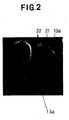
- Fig. 2 is a photograph showing cross-sections of conjugated fibers 13a used to make the nonwoven fabric 1 and Fig. 3 is a diagram tracing the conjugated fibers 13a in the photograph of Fig. 2 .
- a plurality of the conjugated fibers 13a appearing in Fig. 2 are substantially identical one to another.
- Each of these fibers 13a has a diameter of 25 ⁇ m to 30 ⁇ m and comprises a single elastic fiber component 21 and three inelastic fiber components 22 separably attaching to the surface of the elastic fiber component 21 substantially at regular intervals in a circumferential direction.
- the conjugated fiber 13a is substantially identical to the conjugated fiber component 13 depicted in Fig. 1 in construction as well as in composition.
- the conjugated fiber 13a can be obtained by extruding simultaneously an elastic thermoplastic polymer to form the elastic fiber component 21 and an inelastic thermoplastic polymer to form the inelastic fiber component 22 through nozzles of an extruder for melt spinning well known in the art.
- the elastic fibrous component 21 has on its circumferential surface first curved surface portions 51 each bulging radially outward from an axis of the elastic fibrous component 21 and second surface portions 52 each depressed radially toward the axis of the elastic first fibrous component 21 so that these first and second surface portions 51, 52 alternately appearing in the circumferential direction of the elastic fibrous component 21.
- the inelastic fibrous component 22 comprises three inelastic fibrous components 22a, 22b, 22c extending in the longitudinal direction of the elastic fibrous component 21 in the grooves 53a, 53b, 53c, respectively.
- the first polymer to be used to obtain the elastic fiber component 21 includes a thermoplastic polyurethane, a thermoplastic polyurethane containing lubricant and any other thermoplastic elastomers.
- the second polymer to be used to obtain the inelastic fiber component 22 includes thermoplastic polymer which is incompatible with the first polymer and stretches inelastically.
- the term "incompatible" used herein means that a conjugation strength of the inelastic fiber component 22 to the elastic fiber component 21 is relatively low and the inelastic fiber component 22 can be easily separated or split from the elastic fiber component 21, when the conjugated fiber 13a is stretched.
- the second polymer having such properties may be selected from the group including polyolefine polymer such as polyethylene or polypropylene and polyamide polymer such as nylon.
- the inelastic fiber 12 of polypropylene has preferably crystallinity less than 30 % and, more preferably, less than 20 % and does not include a fiber to be deemed as a hard elastic fiber.
- the crystallinity of the inelastic fiber 12 is measured by a DSC method in the present invention.
- the first elastic fiber component 21 may be made by thermoplastic polyurethane containing a lubricant such as fatty amide to facilitate the inelastic fiber component 22 to be separated easily from the elastic fiber component 21.
- An example of the elastic fibrous component 21 is a thermoplastic polyurethane whose melt viscosity based on JIS K 7311 is 23 x 10 3 - 180 x 10 3 poise.
- An example of the inelastic fiber component 22 is a polypropylene whose Melt Flow Rate (MFR) is 30 at 230°C and 2.16 kg/cm 2 .
- MFR Melt Flow Rate
- a preferable weight ratio of the elastic fibrous component 21 to the inelastic fibrous component 22 is 20:80 - 90:10.
- the inelastic fibrous components 22 associated with each elastic fibrous component 21 have a circumferential length occupying 40 % to 90 % of the whole circumferential length of the composite fiber 13a.
- the areas and shapes of the elastic fibrous component 21 and the inelastic fibrous component 22 in the cross-section of the conjugated fiber 13a are formed in such a way that the elastic fiber 11 from the elastic fibrous component 21 may have a fineness of 0.1 - 10 dtx and the inelastic fiber 12 from the inelastic fibrous component 22 may have a fineness of 0.05 - 2 dtx and less than that of the elastic fiber 11.
- a preferable inelastic fibrous component 22 may have a flat cross-section such as an oval shape and the inelastic fiber 12 derived from the inelastic fibrous component 22 may have also a flat corss-section. If the inelastic fiber 12 has a flat cross-section, the length of the long axis may be longer than two times of the length of the short axis so that the inelastic fiber 12 can be easily bent.
- the nonwoven fabric 1 of Fig. 1 is formed in a manner as will be described.
- the conjugated fiber 13a of continuous type is used.
- a plurality of conjugated fibers 13a is supplied in a machine direction to make a web having a basis weight of 10 g/m 2 to 500 g/m 2 .
- the conjugated fibers 13a may be joined or intertwined together in an inseparable manner
- an appropriate treatment for example, by embossing the web under heating or by jetting high pressure columnar water to the web or by blowing a heated air to the web.
- This web may be stretched within an elastic range of the elastic fibrous component 21 and under a failure point of the inelastic fibrous component 22, for example, by 70 % or more in one direction or in two directions along which the attaching areas 16 are formed intermittently. Thereafter, the web is relieved from the stretched condition and is contracted by the elastic recovery force of the elastic fiber component 21 to obtain the nonwoven fabric 1 depicted in Fig.
- the conjugated fiber 13a is separated or split along the interfaces of the elastic fiber component 21 and the inelastic fiber components 22 into one elastic fiber 11 and three inelastic fiber components 12.
- the inelastic fibers 12 also elongate so as to be permanently deformed and a diameter of each inelastic fiber 12 is reduced.
- the elastic fibers 11 contract so as to describe a substantially straight line or a gentle curve while each of the inelastic fibers 12 longer than the elastic fiber 11 describes a curve which is more complicated than the elastic fibers 11 and intersect the elastic fibers 11 and the inelastic fibers 12.
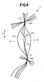
- Fig. 4 is a scale-enlarged plan view showing the elastic fibers 11a representing the elastic fiber 11 and the inelastic fibers 12a, 12b, 12c representing the inelastic fiber 12 on the upper surface 2 of the nonwoven fabric 1 of Fig. 1 obtained in the manner as has been described above
- Fig. 5 is a sectional view taken along a line V-V in Fig. 4 .
- the elastic fiber component 21 and the inelastic fiber components 22 of the conjugated fiber 13a are not separated, and therefore, the conjugated fiber 13a forms the conjugated fiber regions 13.
- the elastic fiber 11a describes a substantially straight line while the inelastic fibers 12a, 12b, 12c describe various curves.
- the inelastic fiber 12b are intersecting the elastic fiber 11a so as to provide crossing points. At the crossing points the elastic fiber 11a lies inside and the inelastic fiber 12b lies outside in the thickness direction of the nonwoven fabric 1.
- the inelastic fibers 12a, 12b, 12c are distributed around the elastic fiber 11a so as to surround the elastic fiber 11a.
- Fig. 6 is a scale-enlarged perspective view of the elastic fiber 11a of Fig. 5 .
- the circumferential surface of the elastic fiber 11a is defined by first curved surface portions 61 each radially bulging outward from an axis of the elastic fiber 11a with a relatively small curvature radius and second curved surface portions 62 each radially depressed toward the axis of the elastic fiber 11a so that these first and second curved surface portions 61, 62 alternately appear on the circumferential surface of the elastic fiber 11a.
- the second curved surface portion 62 lies between each pair of the first curved surface portions 61 neighboring to each other in the circumferential direction and these first and second curved surface portions 61, 62 cooperate together to form a groove 63 extending in the longitudinal direction of the elastic fiber 11a.
- These first curved surface portion 61, second curved surface portion 62 and groove 63 respectively correspond to the first surface portion 51, the second surface portion 52 and the groove 53 of the conjugated fiber 13a depicted by Fig. 3 .
- the elastic fiber 11a comes in contact with the article wearer's skin 69 indicated by imaginary lines merely in the vicinity of the first curved surface portions 61 but the second curved surface portions 62 rarely comes in contact with the skin 69.
- the circumferential surface of the elastic fiber 11a possibly coming in contact with the skin 69 is limited to an extremely small area having a small curvature radius.
- the surface area of the elastic fiber 11a coming in contact with the skin 69 is substantially reduced.
- the nonwoven fabric 1 according to the invention can be implemented also in a manner that not the upper surface 2 but the lower surface 3 is constructed as depicted in Fig. 1 or the both surfaces 2, 3 are constructed as depicted in Fig. 1 .
- Fig. 7 is a view similar to Fig. 5 showing the nonwoven fabric 1 being pulled in the direction A indicated in Fig. 4 .
- the inelastic fibers 12a, 12b, 12c of Fig. 5 move in directions indicated by arrows P, Q, R and get nearer to the elastic fiber 11a as the elastic fiber 11a is stretched in the direction A so that these inelastic fibers 12a, 12b, 12c may closely surround the elastic fiber 11a as shown in Fig. 7 .
- the touch and slip properties of the nonwoven fabric 1 may be further similar to the smooth touch and high slip properties of the inelastic fibers 11.
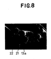
- Figs. 8 and 9 are views similar to Figs. 2 and 3 , exemplarily showing the conjugated fiber 13a suitably used in the present invention.
- This conjugated fiber 13a has a diameter of about 15 ⁇ and consists of the elastic fibrous component 21 presenting a semicircular cross-section and the inelastic fibrous component 22 presenting a semicircular cross-section which are separably attached together.
- the conjugated fiber 13a thus presents a substantially circular cross-section and the inelastic fibrous component 22 appearing on a circumferential surface of this conjugated fiber 13a occupies approximately 50% of the circumferential length of the conjugated fiber 13a.
- a length of the inelastic fiber derived from the inelastic fibrous component 22 is longer than the elastic fiber derived from the elastic fibrous component 21.
- the inelastic fibers function to prevent the elastic fibers from coming in direct contact with the article wearer's skin. Consequently, the nonwoven fabric obtained from these conjugated fibers 13a exhibits a smooth touch and high slip properties to the article wearer's skin although a level of its slip properties can not be comparative to those exhibited by the nonwoven fabric 1 depicted in Fig. 1 .
- the nonwoven fabric 1 of the invention may be formed using the web of the conjugated fiber 13a comprising the elastic fibrous component 21 having the groove 53 as shown in Fig. 3 and the inelastic fibrous component 22 extending in this groove 53, it is easy to obtain the inelastic fiber 12 which has a fineness smaller than a fineness of the elastic fiber 11.
- Figs. 10A, 10B and 10C exemplarily illustrate the cross-sections of the conjugated fibers 13a.
- the conjugated fiber 13a depicted in Fig. 10A presents a cross-section distinguished from that of the conjugated fiber 13a depicted in Fig. 9 in that the elastic fibrous component 21 is formed with a single groove 53.
- the elastic fibrous component 21 is formed with a pair of grooves 53.
- the elastic fibrous component 21 is formed with four grooves 53. In this manner, it is possible without departing from the scope of the invention to form the elastic fibrous component 21 with a selective number of the grooves 53 in a range of one to sixteen.
- Fig. 11 is a side view of a tester 70 used in the present invention to evaluate the nonwoven fabric with respect to its slip properties.
- the tester 70 comprises a plate 71 driven by an electric motor 73 so that its angle ⁇ of a gradient relative to the horizontal plane may be increased at a predetermined rate and a block 72 to be covered with the nonwoven fabric to be evaluated.
- the plate 71 has its upper surface formed of stainless steel having a surface roughness of 12.5s as measured in accordance with JIS B 0601.
- the block 72 is made of stainless steel having a weight adjusted to exert a surface pressure of 10g/cm 2 upon the nonwoven fabric.
- the nonwoven fabric is attached to the block 72 so as to cover the entire lower surface of the block 72.
- the plate 71 supporting the block 72 is rotated around a pivot 74 so that the angle ⁇ increases at a rate of 2°/sec until the block 72 begins to slip over the upper surface of the plate 71.
- the angle ⁇ at which the block 72 begins to slip is defined as a slip angle as.
- clothing fabric for men' s and women' s shirts and pants as undergarments made of 100 % cotton exhibit the slip angle ⁇ s in a range of about 21° to about 25°.
- TABLE 1 indicates the slip angle ⁇ s exhibited by the examples of nonwoven fabric of the conjugated fiber 13a depicted in Figs. 2 and 3 and control nonwoven fabrics.
- the nonwoven fabrics of the invention were obtained by subjecting the web having a basis weight of 50g/m 2 to heat embossing both in the machine direction and in the cross direction.
- the conjugated fiber 13a consisted of thermoplastic polyurethane and polypropylene at a weight ratio in a range of 84.4 : 15.6 to 67.9 : 32.1 and polypropylene occupied about 70 to 90 % of the circumferential length of the conjugated fiber 13a.
- the comparative embodiments of nonwoven fabric were made of thermoplastic polyurethane fiber or polypropylene fiber and obtained by subjecting the web having a basis weight of 50 g/m 2 to heat embossing in the same manner as in the case of embodiments of the invention. Both in the embodiments of the invention and in the comparative embodiments, a plurality of heat embossed zones each of 0.3 mm 2 were formed at a pitch of 2 mm in the machine direction as well as in the cross direction. As will be apparent from TABLE 1, the slip angle ⁇ s of the nonwoven fabric 1 depends on the percentage by which polypropylene as the inelastic fibrous component 22 occupies the circumferential length of the conjugated fiber 13a.
- the invention allows the slip angle ⁇ s of the nonwoven fabric 1 to be controlled by adjusting the proportion of the inelastic fibrous component 22 occupying the circumferential length of the conjugated fiber 13a.
- the slip angle ⁇ s of the upper surface 2 and/or the lower surface 3 is controlled preferably in a range of 25° to 40°.
- the conjugated fiber 13a consisting of thermoplastic polyurethane and polypropylene at a weight ratio in a range of 20 : 80 to 90 : 10. It is also possible to use the conjugated fiber 13a in which polypropylene occupies 40 to 90% of the circumferential length of this conjugated fiber 13a.
- Constituents of conjugated fiber (wt%) Length occupied by polypropylene in the whole peripheral length of conjugate fiber (%) Slip angle ⁇ s Thermoplastic polyurethane Polypropylene Example 1 84.4 15. 6 70. 92 39.3 Example 2 76. 5 23. 5 75. 04 34.3 Example 3 67. 9 32.1 86.07 30.3 Control 1 100 - 0 49.1 Control 2 ⁇ 100 100 21.3
- the nonwoven fabric of the present invention can be used industrially for disposable wearable articles and the nonwoven fabric can be industrially manufactured through the manufacturing process of the present invention.
Description
- The present invention relates to an elastically stretchable nonwoven fabric having a smooth touch to skin and also to a process for making the same.
- Japanese Patent Application Publication No.
1994-184897 - Japanese Patent Application Publication No.
1997-512313 - Japanese Patent Application Publication No.
1992-11021 - Japanese Patent Application Publication No.
1997-316748 - Japanese Patent Publication No.
3262803 - Japanese Patent Application Publication No.
1997-291454 -
JP 05131580 -
EP-A-1184163 discloses an elastically stretchable composite sheet including an elastically stretchable first web and an inelastically stretchable second web of thermoplastic synthetic resin fiber which is intermittently bonded to the first web, and a process for making the same. - In the web and the nonwoven fabric disclosed in the above-cited Publication Nos. 1994-184897 and 1997-512313, respectively, the fibrous layer made of elastically stretchable polymer is exposed on the surface of the fabric. The fibers made of such polymer exhibit a relatively high friction coefficient and correspondingly rough touch. The elastically stretchable web or non-woven fabric formed by laminating the fibrous layers tend to be a thick one.
- The conjugated thread and the fabric disclosed in the above-cited Publication Nos. 1992-11021 and 1997-316748, use the core-sheath type conjugated fiber of which the core is formed by elastomeric fiber and the sheath is formed by non-elastomeric fiber. The sheath functions to cover the elastically stretchable polymer, i.e., the elastomeric fiber and thereby to prevent the elastomeric fiber from coming in direct contact with the user's body. In this way, the conjugated thread as well as the fabric disclosed in the above-cited Publications are able to offer a smooth touch to the skin and a comfortable touch for the user's body. However, the sheath fiber presenting bellows-like wrinkles obstructs the core fiber from elastically contracting and, in consequence, limits an extension coefficient as well as a contraction coefficient of the conjugated thread and the fabric. The conjugated fiber has its sheath formed with the bellows-like wrinkles and therefore it is difficult for these conjugated thread and fabric to offer the soft and flexible touch peculiar to the fiber having a small fineness.
- According to the above-cited Publication No. 3262803, the multi-component thermoplastic filaments are split to a plurality of more fine filaments within the Lurgi duct and then formed into a nonwoven fabric. Repective components constituting the multi-component thermoplastic filament appear on the surface of this nonwoven fabric in a form of more fine filaments in accordance with the mixing proportion of these components. If one of the components is a thermoplastic elastomer, the filament of such a thermoplastic elastomer will be exposed on the surface of the nonwoven fabric and a wearer of a wearable article made of the nonwoven fabric may experience a rough touch with poor slip properties of the nonwoven fabric depending on a proportion of the thermoplastic elastomer filament.
- According to the above Publication No. 1997-291454, the elastically stretchable conjugated fiber consisting of the hard elastic member comprising polypropylene as the first component and the thermoplastic elastomer as the second component are intermittently welded into an elastically stretchable nonwoven fabric. The circumferential surface of the conjugated fiber is defined by zones occupied by polypropylene and zones occupied by the elastomer. In this case the thermoplastic elastomer is inevitably exposed on the surface of the nonwoven fabric. Consequently, this nonwoven fabric may have a rough touch and poor slip properties. The above Publication No. 1997-291454 describes as one of embodiments a sheath-and-core type conjugated fiber of which the sheath is formed by polypropylene as the first component and the core is formed by the elastomer comprising ethylene-α-olefin copolymer as the second component. The elastic stretchability of such a conjugated fiber is governed by the stretchability of the hard elastic member comprising polypropylene and the stretchability of the elastomer might be thereby suppressed.
- It is an object of the present invention to provide a novel elastic nonwoven fabric adapted to have a broad elastic extension range as well as a broad elastic contraction range and to offer a smooth touch to the skin.
- The present invention has a first aspect relating to a nonwoven fabric and a second aspect relating to a process for making the nonwoven fabric.
- According to the first aspect of the invention, there is provided an elastically stretchable nonwoven fabric as defined in
claim 1. - The first aspect of the invention can be implemented in preferable manners as follows:
- (1) the first and second fibers intersect with each other in such a manners that the first fiber lies inside and the second fiber lies outside in any one of the first and second surfaces;
- (2) the first fiber has on its circumferential surface first curved surfaces each bulging radially outward from an axis of the first fiber and second curved surfaces each depressed radially toward the axis of the first fiber, the first and second curved surfaces alternately appearing in a circumferential direction of the first fiber, and each pair of the first curved surfaces neighboring to each other in the circumferential direction cooperate with the second curved surface lying between the pair of the first curved surfaces neighboring to each other to form a groove extending in a longitudinal direction of the first fiber so that the second curved surface defines a bottom of the groove. In the case that the nonwoven fabric having such a first fiber is used for a wearable article, these are little chances where the first fiber contacts the skin of a wearer of the article, because the curved surfaces of the first fiber cannot contact the skin.
- (3) one of the first and second surfaces has a slip angle of 25° to 40°. The nonwoven fabric having the slip angle of such a range is suitable for a wearable article and other products.
- (4) the first polymer is selected from the group consisting of thermoplastic polyurethane and thermoplastic polyurethane containing a lubricant and the second polymer is selected from the group consisting of polyolefin-based polymer and polyamide-based polymer.
- The object set forth above is achieved according to the second aspect of the invention as defined in claim 5.
- The second aspect of the invention can be implemented in preferable manners as follow:
- (1) the first fibrous component of the conjugated fiber has on its circumferential surface first curved surfaces each bulging radially outward from an axis of the first fibrous component and second curved surfaces each depressed radially toward an axis of the first fibrous component, the first and second curved surfaces alternately appearing in the circumferential direction of the first fibrous component, and each pair of the first curved surfaces neighboring to each other in the circumferential direction cooperate with the second curved surface lying between the pair of the first curved surfaces neighboring to each other to form a groove extending in the longitudinal direction of the first fibrous component so that the second fibrous component extends in parallel to the first fibrous component in the groove.
- (2) the circumferential length of the conjugated fiber occupied by the second fibrous component is in a range of 40 to 90% of the whole circumferential length of the conjugated fiber.
- (3) the number of the second fibrous component constituting the conjugated fiber is in a range of 1 to 16 per one of the first fibrous component.
- (4) the first polymer is selected from the group consisting of thermoplastic polyurethane and thermoplastic polyurethane containing a lubricant and the second polymer is selected from the group consisting of polyolefin-based polymer and polyamide-based polymer.
- In the present invention the slip angle is measured in an apparatus depicted by an accompanying drawing, i.e.
Fig. 11 . The measuring method of the slip angle is included in the explanation ofFig. 11 . - The nonwoven fabric according to the present invention, even when the nonwoven fabric contains the elastic fiber, allows the smooth touch of the nonwoven fabric to the article wearer' s skin to be adjusted by placing in the vicinity of each of the elastic fiber at least one inelastic fiber which is longer than the elastic fiber. The smooth touch to the article wearer's skin can be effectively adjusted by placing a plurality of the inelastic fibers in the vicinity of the elastic fiber so as to surround this elastic fiber. Since the segment of the inelastic fiber defined between a pair of the neighboring attaching areas in which the inelastic fiber is inseparably attached to the elastic fiber is longer than the associated segment of the elastic fiber, the elastic stretchability of the elastic fibers as well as the nonwoven fabric is not disturbed by the inelastic fiber.
- The process according to the present invention for making the nonwoven fabric is primarily characterized in that the conjugated fibers consisting of the elastic fibrous component and the inelastic fibrous component separably attached to the surface of the elastic fibrous component are split into the respective fibrous components so that the inelastic fibers having a smaller fineness may surround the elastic fiber having a larger fineness. In this way, the process according to the present invention can provide thin nonwoven fabric which is elastically stretchable and contractible and allows also at least one of the upper and lower surfaces of the nonwoven fabric to present a smooth touch and high slip properties of the inelastic fiber having a smaller fineness instead of those of the elastic fiber having a larger fineness.
-
-
Fig. 1 is a perspective view showing a typical embodiment of a nonwoven fabric; -
Fig. 2 is a photograph showing cross-sections of conjugated fibers; -
Fig. 3 is a diagram tracing the conjugated fibers in photograph ofFig. 2 ; -
Fig. 4 is a scale-enlarged plan view showing a part ofFig. 1 ; -
Fig. 5 is a sectional view taken along a line V-V inFig. 4 ; -
Fig. 6 is a scale-enlarged portion ofFig. 5 ; -
Fig. 7 is a view similar toFig. 5 illustrating a relative position of the respective fibers when the nonwoven fabric is stretched; -
Fig. 8 is a photograph similar toFig. 2 showing a preferred embodiment of the present invention; -
Fig. 9 is a diagram similar toFig. 3 showing the preferred embodiment; -
Figs. 10A, 10B and 10C are sectional views of the conjugated fibers; and -
Fig. 11 is a side view of a tester. - Details of the nonwoven fabric and the process for making the same according to the present invention will be more fully understood from the description given hereunder with reference to the accompanying drawings.
- A substantially hexahedral fragment of
nonwoven fabric 1 shown inFig. 1 in a perspective view has upper andlower surfaces nonwoven fabric 1 and side surfaces defined bycut surfaces lower surfaces nonwoven fabric 1 comprises elasticallystretchable fibers 11 made of a first thermoplastic polymer, inelasticallystretchable fibers 12 made of a second thermoplastic polymer andconjugated fiber regions 13 formed by theelastic fibers 11 and theinelastic fibers 12 which are joined together side by side. In thenonwoven fabric 1, thesefibers conjugated fiber regions 13 are welded, adhesively bonded or mechanically intertwined together at a plurality of attachingarea 16 so that thesefibers conjugated fiber regions 13 may be substantially fixed in thearea 16. Theelastic fibers 11 and theinelastic fibers 12 are obtained by splitting eachconjugated fiber 13a corresponding to each of theconjugated fiber regions 13 into afiber component 21 and a fiber component 22 (seeFig. 2 ) during a production process as will be described later. As will be seen inFig. 1 , theconjugated fiber regions 13 principally lie in the vicinity of the respective attachingarea 16. - In the
nonwoven fabric 1, theelastic fibers 11 have a fineness in a range of 0.1 dtx to 10 dtx and theinelastic fibers 12 have a fineness in a range of 0.05 dtx to 2 dtx. The fineness of theinelastic fiber 12 is preferably smaller than the fineness of theelastic fiber 11. Except for thearea 16, in the surrounding area of each of theelastic fibers 11, one to sixteen of theinelastic fibers 12 extends or extend between the neighboringareas 16, for example, thearea 16a and thearea 16b depicted inFig. 1 . In thenonwoven fabric 1, at least threeinelastic fibers elastic fiber 11a (seeFig. 5 ) and wrap around thiselastic fiber 11a. In the vicinity of theareas inelastic fibers elastic fiber 11a. Thus theelastic fiber 11 and theinelastic fibers 12 are repeatedly joined together (at the areas 16) and spaced apart from each other in a longitudinal direction of theelastic fiber 11. Between the neighboringareas inelastic fibers elastic fiber 11a, and theelastic fiber 11a is substantially rectilinear and theinelastic fibers upper surface 2 and preferably on thelower surface 3, the ratio of the number of theelastic fiber 11a to the number of theinelastic fibers elastic fiber 11a and theinelastic fibers cut surface 4a and the number of these ends approximately corresponds to the number of theelastic fibers 11a and theinelastic fibers elastic fibers 11a to the ends of theinelastic fibers cut surface 4a is approximately 1:3. - uses of the
nonwoven fabric 1 are not specified. Thenonwoven fabric 1 can be used for a wearable article, for example, a disposable diaper, disposable pants or a disposable medical gown, and household goods, for example, disposable wipes. In thenonwoven fabric 1 used in these fields it is preferable that a straight distance between the neighboring attachingareas elastic fiber 11a is 0.5 - 10 mm, and that the lengths of theinelastic fibers areas elastic fiber 11a. - The
elastic fibers 11 are elastically stretched when thenonwoven fabric 1 of the arrangement as has been described above is held with the hands and pulled in a direction A or in a direction B intersecting orthogonally the direction A, whereupon theinelastic fibers 12 are oriented to extend in the direction A or in the direction B. Upon releasing from the pulled condition, an elastic recovery force of theelastic fibers 11 causes thenonwoven fabric 1 to shrink to the state ofFig. 1 . It is well known that such an elastic material as theelastic fiber 11 has a rubbery rough touch, but the presence of the pluralinelastic fibers 12 wrapping around the respectiveelastic fibers 11 is effective to provide the upper andlower surfaces nonwoven fabric 1 with a smooth and slipping touch similar to that of theinelastic fiber 12. In addition, the smooth and slipping touch of thenonwoven fabric 1 of the present invention can be controlled by a fineness, a shape of the cross section and a number of theinelastic fiber 12. The fineness of theinelastic fibers 12 may be minimized, for example, in the order of 0.5 dtx to 1.5 dtx to make the touch of the upper andlower surfaces -
Fig. 2 is a photograph showing cross-sections ofconjugated fibers 13a used to make thenonwoven fabric 1 andFig. 3 is a diagram tracing theconjugated fibers 13a in the photograph ofFig. 2 . A plurality of theconjugated fibers 13a appearing inFig. 2 are substantially identical one to another. Each of thesefibers 13a has a diameter of 25 µm to 30 µm and comprises a singleelastic fiber component 21 and threeinelastic fiber components 22 separably attaching to the surface of theelastic fiber component 21 substantially at regular intervals in a circumferential direction. Theconjugated fiber 13a is substantially identical to theconjugated fiber component 13 depicted inFig. 1 in construction as well as in composition. Theconjugated fiber 13a can be obtained by extruding simultaneously an elastic thermoplastic polymer to form theelastic fiber component 21 and an inelastic thermoplastic polymer to form theinelastic fiber component 22 through nozzles of an extruder for melt spinning well known in the art. Theelastic fibrous component 21 has on its circumferential surface first curvedsurface portions 51 each bulging radially outward from an axis of theelastic fibrous component 21 andsecond surface portions 52 each depressed radially toward the axis of the elastic firstfibrous component 21 so that these first andsecond surface portions elastic fibrous component 21. Each pair offirst surface portions second surface portion 52 lying between the pair of neighboringfirst surface portions 51 to form agroove 53 wherein thesecond surface portion 51 defines a bottom of thegroove 53 and a total of threegrooves elastic fibrous component 21. Theinelastic fibrous component 22 comprises three inelasticfibrous components elastic fibrous component 21 in thegrooves - The first polymer to be used to obtain the
elastic fiber component 21 includes a thermoplastic polyurethane, a thermoplastic polyurethane containing lubricant and any other thermoplastic elastomers. The second polymer to be used to obtain theinelastic fiber component 22 includes thermoplastic polymer which is incompatible with the first polymer and stretches inelastically. The term "incompatible" used herein means that a conjugation strength of theinelastic fiber component 22 to theelastic fiber component 21 is relatively low and theinelastic fiber component 22 can be easily separated or split from theelastic fiber component 21, when theconjugated fiber 13a is stretched. The second polymer having such properties may be selected from the group including polyolefine polymer such as polyethylene or polypropylene and polyamide polymer such as nylon. Either homopolymer or copolymer of polypropylene can be used. Theinelastic fiber 12 of polypropylene has preferably crystallinity less than 30 % and, more preferably, less than 20 % and does not include a fiber to be deemed as a hard elastic fiber. The crystallinity of theinelastic fiber 12 is measured by a DSC method in the present invention. The firstelastic fiber component 21 may be made by thermoplastic polyurethane containing a lubricant such as fatty amide to facilitate theinelastic fiber component 22 to be separated easily from theelastic fiber component 21. An example of theelastic fibrous component 21 is a thermoplastic polyurethane whose melt viscosity based on JIS K 7311 is 23 x 103 - 180 x 103 poise. An example of theinelastic fiber component 22 is a polypropylene whose Melt Flow Rate (MFR) is 30 at 230°C and 2.16 kg/cm2. A preferable weight ratio of theelastic fibrous component 21 to theinelastic fibrous component 22 is 20:80 - 90:10. In a preferable case of theconjugated fiber 13a, the inelasticfibrous components 22 associated with eachelastic fibrous component 21 have a circumferential length occupying 40 % to 90 % of the whole circumferential length of thecomposite fiber 13a. The areas and shapes of theelastic fibrous component 21 and theinelastic fibrous component 22 in the cross-section of theconjugated fiber 13a are formed in such a way that theelastic fiber 11 from theelastic fibrous component 21 may have a fineness of 0.1 - 10 dtx and theinelastic fiber 12 from theinelastic fibrous component 22 may have a fineness of 0.05 - 2 dtx and less than that of theelastic fiber 11. A preferable inelasticfibrous component 22 may have a flat cross-section such as an oval shape and theinelastic fiber 12 derived from theinelastic fibrous component 22 may have also a flat corss-section. If theinelastic fiber 12 has a flat cross-section, the length of the long axis may be longer than two times of the length of the short axis so that theinelastic fiber 12 can be easily bent. - Using such a
conjugated fiber 13a, thenonwoven fabric 1 ofFig. 1 is formed in a manner as will be described. Preferably, theconjugated fiber 13a of continuous type is used. A plurality ofconjugated fibers 13a is supplied in a machine direction to make a web having a basis weight of 10 g/m2 to 500 g/m2. In the course of making such a web, the attachingareas 16 depicted inFig. 1 in which theconjugated fibers 13a are joined or intertwined together in an inseparable manner may be formed intermittently in one of the machine direction and the cross direction intersecting orthogonally the machine direction by an appropriate treatment, for example, by embossing the web under heating or by jetting high pressure columnar water to the web or by blowing a heated air to the web. This web may be stretched within an elastic range of theelastic fibrous component 21 and under a failure point of theinelastic fibrous component 22, for example, by 70 % or more in one direction or in two directions along which the attachingareas 16 are formed intermittently. Thereafter, the web is relieved from the stretched condition and is contracted by the elastic recovery force of theelastic fiber component 21 to obtain thenonwoven fabric 1 depicted inFig. 1 . Between each pair of the neighboring attachingareas areas Fig. 1 , theconjugated fiber 13a is separated or split along the interfaces of theelastic fiber component 21 and theinelastic fiber components 22 into oneelastic fiber 11 and threeinelastic fiber components 12. At the same time, theinelastic fibers 12 also elongate so as to be permanently deformed and a diameter of eachinelastic fiber 12 is reduced. In thenonwoven fabric 1 obtained by contracting the web, between each pair of the neighboringareas elastic fibers 11 contract so as to describe a substantially straight line or a gentle curve while each of theinelastic fibers 12 longer than theelastic fiber 11 describes a curve which is more complicated than theelastic fibers 11 and intersect theelastic fibers 11 and theinelastic fibers 12. -
Fig. 4 is a scale-enlarged plan view showing theelastic fibers 11a representing theelastic fiber 11 and theinelastic fibers inelastic fiber 12 on theupper surface 2 of thenonwoven fabric 1 ofFig. 1 obtained in the manner as has been described above, andFig. 5 is a sectional view taken along a line V-V inFig. 4 . In the vicinity of theareas Fig. 4 , theelastic fiber component 21 and theinelastic fiber components 22 of theconjugated fiber 13a are not separated, and therefore, theconjugated fiber 13a forms theconjugated fiber regions 13. Between each pair of the neighboringareas elastic fiber 11a separated from theinelastic fibers elastic fiber 11a describes a substantially straight line while theinelastic fibers inelastic fiber 12b are intersecting theelastic fiber 11a so as to provide crossing points. At the crossing points theelastic fiber 11a lies inside and theinelastic fiber 12b lies outside in the thickness direction of thenonwoven fabric 1. On the cut surface shown inFig. 5 , theinelastic fibers elastic fiber 11a so as to surround theelastic fiber 11a. -
Fig. 6 is a scale-enlarged perspective view of theelastic fiber 11a ofFig. 5 . The circumferential surface of theelastic fiber 11a is defined by firstcurved surface portions 61 each radially bulging outward from an axis of theelastic fiber 11a with a relatively small curvature radius and secondcurved surface portions 62 each radially depressed toward the axis of theelastic fiber 11a so that these first and secondcurved surface portions elastic fiber 11a. The secondcurved surface portion 62 lies between each pair of the firstcurved surface portions 61 neighboring to each other in the circumferential direction and these first and secondcurved surface portions groove 63 extending in the longitudinal direction of theelastic fiber 11a. These firstcurved surface portion 61, secondcurved surface portion 62 andgroove 63 respectively correspond to thefirst surface portion 51, thesecond surface portion 52 and thegroove 53 of theconjugated fiber 13a depicted byFig. 3 . - With a wearable article made of the
nonwoven fabric 1 including theelastic fiber 11 and theinelastic fiber 12 depicted inFigs. 4 ,5 and6 , the article wearer's skin readily comes in contact with theinelastic fibers elastic fiber 11a. Consequently, a touch and slip properties of thenonwoven fabric 1 are similar to those of theinelastic fiber 12. This is very true, when the number of theinelastic fibers 12 intersecting theelastic fiber 11a is relatively large as in the case depicted inFig. 4 and theelastic fiber 11a having a rough touch and poor slip properties to the article wearer's skin is embedded among theinelastic fibers 12 on theupper surface 2 of thenonwoven fabric 1. As will be apparent fromFig. 6 , theelastic fiber 11a comes in contact with the article wearer'sskin 69 indicated by imaginary lines merely in the vicinity of the firstcurved surface portions 61 but the secondcurved surface portions 62 rarely comes in contact with theskin 69. In this way, the circumferential surface of theelastic fiber 11a possibly coming in contact with theskin 69 is limited to an extremely small area having a small curvature radius. Compared to an elastic fiber having a circular cross-section of the same area as that of theelastic fiber 11a, the surface area of theelastic fiber 11a coming in contact with theskin 69 is substantially reduced. The smaller the surface area of theelastic fiber 11a possibly coming in contact with theskin 69 is, the higher the smooth touch and slip properties of thenonwoven fabric 1 to the article wearer' sskin 69 are. Even if theelastic fiber 11a comes in contact with theskin 69, a gap is left in many cases between theskin 69 and thegrooves 63 of theelastic fiber 11a and such a gap serves to relieve theskin 69 from a high humid condition since the gap allows a vapour generated within the article to escape outward. Thenonwoven fabric 1 according to the invention can be implemented also in a manner that not theupper surface 2 but thelower surface 3 is constructed as depicted inFig. 1 or the bothsurfaces Fig. 1 . -
Fig. 7 is a view similar toFig. 5 showing thenonwoven fabric 1 being pulled in the direction A indicated inFig. 4 . Theinelastic fibers Fig. 5 move in directions indicated by arrows P, Q, R and get nearer to theelastic fiber 11a as theelastic fiber 11a is stretched in the direction A so that theseinelastic fibers elastic fiber 11a as shown inFig. 7 . If most of theinelastic fibers 12 ofFig. 7 , orientate in the direction A, the touch and slip properties of thenonwoven fabric 1 may be further similar to the smooth touch and high slip properties of theinelastic fibers 11. -
Figs. 8 and9 are views similar toFigs. 2 and3 , exemplarily showing theconjugated fiber 13a suitably used in the present invention. Thisconjugated fiber 13a has a diameter of about 15µ and consists of theelastic fibrous component 21 presenting a semicircular cross-section and theinelastic fibrous component 22 presenting a semicircular cross-section which are separably attached together. Theconjugated fiber 13a thus presents a substantially circular cross-section and theinelastic fibrous component 22 appearing on a circumferential surface of thisconjugated fiber 13a occupies approximately 50% of the circumferential length of theconjugated fiber 13a. Also in thenonwoven fabric 1 obtained from the web comprising theseconjugated fibers 13a by stretching the web and then allowing the web to contract, a length of the inelastic fiber derived from theinelastic fibrous component 22 is longer than the elastic fiber derived from theelastic fibrous component 21. With such inelastic fibers flexing and/or curving so as to intersect the elastic fibers, the inelastic fibers function to prevent the elastic fibers from coming in direct contact with the article wearer's skin. Consequently, the nonwoven fabric obtained from theseconjugated fibers 13a exhibits a smooth touch and high slip properties to the article wearer's skin although a level of its slip properties can not be comparative to those exhibited by thenonwoven fabric 1 depicted inFig. 1 . - Since the
nonwoven fabric 1 of the invention may be formed using the web of theconjugated fiber 13a comprising theelastic fibrous component 21 having thegroove 53 as shown inFig. 3 and theinelastic fibrous component 22 extending in thisgroove 53, it is easy to obtain theinelastic fiber 12 which has a fineness smaller than a fineness of theelastic fiber 11. -
Figs. 10A, 10B and 10C exemplarily illustrate the cross-sections of theconjugated fibers 13a. Theconjugated fiber 13a depicted inFig. 10A presents a cross-section distinguished from that of theconjugated fiber 13a depicted inFig. 9 in that theelastic fibrous component 21 is formed with asingle groove 53. In the case of theconjugated fiber 13a depicted inFig. 10B , theelastic fibrous component 21 is formed with a pair ofgrooves 53. Finally, in the case of theconjugated fiber 13a depicted inFig. 10C , theelastic fibrous component 21 is formed with fourgrooves 53. In this manner, it is possible without departing from the scope of the invention to form theelastic fibrous component 21 with a selective number of thegrooves 53 in a range of one to sixteen. -
Fig. 11 is a side view of a tester 70 used in the present invention to evaluate the nonwoven fabric with respect to its slip properties. The tester 70 comprises aplate 71 driven by anelectric motor 73 so that its angle α of a gradient relative to the horizontal plane may be increased at a predetermined rate and ablock 72 to be covered with the nonwoven fabric to be evaluated. Theplate 71 has its upper surface formed of stainless steel having a surface roughness of 12.5s as measured in accordance with JIS B 0601. Theblock 72 is made of stainless steel having a weight adjusted to exert a surface pressure of 10g/cm2 upon the nonwoven fabric. The nonwoven fabric is attached to theblock 72 so as to cover the entire lower surface of theblock 72. Theplate 71 supporting theblock 72 is rotated around apivot 74 so that the angle α increases at a rate of 2°/sec until theblock 72 begins to slip over the upper surface of theplate 71. The angle α at which theblock 72 begins to slip is defined as a slip angle as. The smaller the value of αs is, the higher the slip properties relative to the article wearer's skin are. Based on the tester 70, clothing fabric for men' s and women' s shirts and pants as undergarments made of 100 % cotton exhibit the slip angle αs in a range of about 21° to about 25°. - TABLE 1 indicates the slip angle αs exhibited by the examples of nonwoven fabric of the
conjugated fiber 13a depicted inFigs. 2 and3 and control nonwoven fabrics. The nonwoven fabrics of the invention were obtained by subjecting the web having a basis weight of 50g/m2 to heat embossing both in the machine direction and in the cross direction. Theconjugated fiber 13a consisted of thermoplastic polyurethane and polypropylene at a weight ratio in a range of 84.4 : 15.6 to 67.9 : 32.1 and polypropylene occupied about 70 to 90 % of the circumferential length of theconjugated fiber 13a. The comparative embodiments of nonwoven fabric were made of thermoplastic polyurethane fiber or polypropylene fiber and obtained by subjecting the web having a basis weight of 50 g/m2 to heat embossing in the same manner as in the case of embodiments of the invention. Both in the embodiments of the invention and in the comparative embodiments, a plurality of heat embossed zones each of 0.3 mm2 were formed at a pitch of 2 mm in the machine direction as well as in the cross direction. As will be apparent from TABLE 1, the slip angle αs of thenonwoven fabric 1 depends on the percentage by which polypropylene as theinelastic fibrous component 22 occupies the circumferential length of theconjugated fiber 13a. In other words, the invention allows the slip angle αs of thenonwoven fabric 1 to be controlled by adjusting the proportion of theinelastic fibrous component 22 occupying the circumferential length of theconjugated fiber 13a. When thenonwoven fabric 1 is used in a wearing article, the slip angle αs of theupper surface 2 and/or thelower surface 3 is controlled preferably in a range of 25° to 40°. - In order to control the slip angle αs of the
nonwoven fabric 1, it is possible without departing from the scope of the invention to use, in addition to those indicated as the embodiments, theconjugated fiber 13a consisting of thermoplastic polyurethane and polypropylene at a weight ratio in a range of 20 : 80 to 90 : 10. It is also possible to use theconjugated fiber 13a in which polypropylene occupies 40 to 90% of the circumferential length of thisconjugated fiber 13a.[TABLE 1] Constituents of conjugated fiber (wt%) Length occupied by polypropylene in the whole peripheral length of conjugate fiber (%) Slip angle αs Thermoplastic polyurethane Polypropylene Example 1 84.4 15. 6 70. 92 39.3 Example 2 76. 5 23. 5 75. 04 34.3 Example 3 67. 9 32.1 86.07 30.3 Control 1100 - 0 49.1 Control 2― 100 100 21.3 - The nonwoven fabric of the present invention can be used industrially for disposable wearable articles and the nonwoven fabric can be industrially manufactured through the manufacturing process of the present invention.
Claims (9)
- An elastically stretchable nonwoven fabric comprising elastically stretchable first fibers made of a first polymer and inelastically stretchable second fibers made of a second polymer, said nonwoven fabric being characterized by that:said nonwoven fabric has first and second surfaces as viewed in its thickness direction, said first and second surfaces extending in parallel to each other, said second fiber is bonded to said first fiber at attaching areas formed intermittently along said first fiber and spaced apart from said first fiber between each pair of said attaching areas neighboring to each other, each segment of said second fiber spaced apart from said first fiber between each pair of said attaching areas neighboring to each other being longer than an associated segment of said first fiber, the number of said second fiber is in a range of 3 to 16 per each first fiber
, and said first and second fibers intersect with each other in such a manner that said first fiber lies inside and said second fiber lies outside in one of said first and second surfaces. - The nonwoven fabric according to Claim 1 , wherein said first fiber has on its circumferential surface first curved surfaces each bulging radially outward from an axis of said first fiber and second curved surfaces each depressed radially toward said axis of said first fiber, said first and second curved surfaces alternately appearing in a circumferential direction of said first fiber, and each pair of said first curved surfaces neighboring to each other in said circumferential direction cooperate with said second curved surface lying between said pair of said first curved surfaces neighboring to each other to form a groove extending in a longitudinal direction of said first fiber so that said second curved surface defines a bottom of said groove.
- The nonwoven fabric according to claim 1 or 2 , wherein one of said first and second surfaces has a slip angle of 25° to 40°.
- The nonwoven fabric according to any one of Claims 1 through 3, wherein said first polymer is selected from the group consisting of thermoplastic polyurethane and thermoplastic polyurethane containing a lubricant and said second polymer is selected from the group consisting of polyolefin-based polymer
and polyamide-based polymer. - A process for making an elastically stretchable nonwoven fabric formed by elastically stretchable first fibers made of a first polymer and inelastically stretchable second fibers made of a second polymer, said process comprising steps of:feeding, in a machine direction, a plurality of conjugated fibers each consisting of a first fibrous component made of said first polymer and a second fibrous component extending in parallel to and releasably attached to a surface of said first fibrous component and thereby forming a web from said conjugated fibers having a basis weight in a range of 10 to 500g/m2;forming said web with a plurality of attaching areas intermittently formed in at least one direction of said machine direction and a cross direction intersecting orthogonally said machine direction so that said conjugated fibers can not be separated one from another at said attaching areas;stretching said web at least in said one direction within an elastic range of the first fibrous component and under a failure point of said second fibrous component and thereby separating said first and second fibrous components one from another between each pair of said attaching areas neighboring to each other and permanently deforming said second fibrous component; andallowing said web to contract under an elastic recovery force of said first fibrous component so that said first fiber is obtained from said first fibrous component, said second fiber is obtained from said second fibrous component and said nonwoven fabric is obtained from said web the number of said second fibrous component constituting said conjugated fiber is in a range of 3 to 16 per one of said first fibrous component, said non woven fabric has first and second surfaces as viewed in its thickness direction, said first and second surfaces extending in parallel to each other and said first and second fibers intersect with each other in such a manner that said first fiber lies inside and said second fiber lies outside in one of said first and second surfaces.
- The process according to Claim 6, wherein said first fibrous component of said conjugated fiber has on its circumferential surface first curved surfaces each bulging radially outward from the axis of said first fibrous component and second curved surfaces each depressed radially toward said axis of said first fibrous component, said first and second curved surfaces alternately appearing in a circumferential direction of said first fibrous component, and each pair of said first curved surfaces neighboring to each other in said circumferential direction cooperate with said second curved surface lying between said pair of said first curved surfaces neighboring to each other to form a groove extending in a longitudinal direction of said first fibrous component so that said second fibrous component extends in parallel to said first fibrous component in said groove.
- The process according to claim 5 or 6, wherein the circumferential length of said conjugated fiber occupied by said second fibrous component is in a range of 40 to 90% of the whole circumferential length of said conjugated fiber.
- The process according to any one of claims 5 through 7, wherein the number of said second fibrous component constituting said conjugated fiber is in a range of 1 to 16 per one of said first fibrous component.
- The process according to any one of claims 5 through 8 wherein said first polymer is selected from the group consisting of thermoplastic polyurethane and thermoplastic polyurethane containing a lubricant and said second polymer is selected from the group consisting of polyolefin-based polymer and polyamide-based polymer.
Applications Claiming Priority (5)
| Application Number | Priority Date | Filing Date | Title |
|---|---|---|---|
| JP2002311896 | 2002-09-19 | ||
| JP2002311896 | 2002-09-19 | ||
| JP2003321935A JP4705321B2 (en) | 2002-09-19 | 2003-09-12 | Non-woven |
| JP2003321935 | 2003-09-12 | ||
| PCT/JP2003/012025 WO2004027138A1 (en) | 2002-09-19 | 2003-09-19 | Nonwoven fabric and method for production thereof |
Publications (3)
| Publication Number | Publication Date |
|---|---|
| EP1559822A1 EP1559822A1 (en) | 2005-08-03 |
| EP1559822A4 EP1559822A4 (en) | 2008-06-25 |
| EP1559822B1 true EP1559822B1 (en) | 2012-10-31 |
Family
ID=32032969
Family Applications (1)
| Application Number | Title | Priority Date | Filing Date |
|---|---|---|---|
| EP20030797711 Expired - Lifetime EP1559822B1 (en) | 2002-09-19 | 2003-09-19 | Nonwoven fabric and method for production thereof |
Country Status (9)
| Country | Link |
|---|---|
| US (1) | US20040132374A1 (en) |
| EP (1) | EP1559822B1 (en) |
| JP (1) | JP4705321B2 (en) |
| KR (1) | KR20050057435A (en) |
| CN (1) | CN100402725C (en) |
| AU (1) | AU2003264529A1 (en) |
| CA (1) | CA2498765A1 (en) |
| TW (1) | TW200407478A (en) |
| WO (1) | WO2004027138A1 (en) |
Cited By (1)
| Publication number | Priority date | Publication date | Assignee | Title |
|---|---|---|---|---|
| WO2017176238A1 (en) * | 2016-04-04 | 2017-10-12 | Kimberly-Clark Worldwide, Inc. | Cleaning product with low lint and high fluid absorbency and release properties |
Families Citing this family (29)
| Publication number | Priority date | Publication date | Assignee | Title |
|---|---|---|---|---|
| US20010018579A1 (en) | 1998-12-18 | 2001-08-30 | Walter Klemp | Disposable absorbent garment having stretchable side waist regions |
| US7806880B2 (en) | 2005-03-18 | 2010-10-05 | The Procter & Gamble Company | Pull-on wearable article with informational image |
| US7887522B2 (en) | 2005-03-18 | 2011-02-15 | The Procter And Gamble Company | Pull-on wearable article with informational image |
| WO2006102360A2 (en) * | 2005-03-23 | 2006-09-28 | Allasso Industries, Inc. | Low linting, high absorbency, high strength wipes composed of micro and nano fibers |
| US8663184B2 (en) | 2005-08-05 | 2014-03-04 | The Procter & Gamble Company | Absorbent article with a multifunctional side panel |
| US7432413B2 (en) | 2005-12-16 | 2008-10-07 | The Procter And Gamble Company | Disposable absorbent article having side panels with structurally, functionally and visually different regions |
| US8491558B2 (en) | 2006-03-31 | 2013-07-23 | The Procter & Gamble Company | Absorbent article with impregnated sensation material for toilet training |
| US20070233026A1 (en) * | 2006-03-31 | 2007-10-04 | The Procter & Gamble Company | Absorbent articles with feedback signal upon urination |
| US8057450B2 (en) | 2006-03-31 | 2011-11-15 | The Procter & Gamble Company | Absorbent article with sensation member |
| US8664467B2 (en) | 2006-03-31 | 2014-03-04 | The Procter & Gamble Company | Absorbent articles with feedback signal upon urination |
| CN101454493B (en) * | 2006-05-31 | 2011-08-31 | 花王株式会社 | Stretch nonwoven fabric |
| JP5137337B2 (en) * | 2006-05-31 | 2013-02-06 | 花王株式会社 | Method for manufacturing absorbent article |
| US8235963B2 (en) | 2006-06-07 | 2012-08-07 | The Procter & Gamble Company | Disposable wearable absorbent articles with anchoring systems |
| US20070287983A1 (en) * | 2006-06-07 | 2007-12-13 | Richard Worthington Lodge | Absorbent article having an anchored core assembly |
| JP5112678B2 (en) | 2006-11-27 | 2013-01-09 | ユニ・チャーム株式会社 | Non-woven |
| MX2009005684A (en) | 2006-12-04 | 2009-06-08 | Procter & Gamble | Absorbent articles comprising graphics. |
| JP5238158B2 (en) | 2006-12-25 | 2013-07-17 | ユニ・チャーム株式会社 | Method for producing elastic sheet |
| JP5342751B2 (en) * | 2007-03-30 | 2013-11-13 | ユニ・チャーム株式会社 | Elastic nonwoven fabric |
| US8790325B2 (en) | 2007-09-07 | 2014-07-29 | The Procter & Gamble Company | Disposable wearable absorbent articles with anchoring subsystems |
| US8858523B2 (en) | 2007-09-07 | 2014-10-14 | The Procter & Gamble Company | Disposable wearable absorbent articles with anchoring subsystems |
| US9056031B2 (en) | 2007-09-07 | 2015-06-16 | The Procter & Gamble Company | Disposable wearable absorbent articles with anchoring subsystems |
| US8945079B2 (en) | 2007-09-07 | 2015-02-03 | The Procter & Gamble Company | Disposable wearable absorbent articles with anchoring subsystems |
| US8668679B2 (en) | 2007-09-07 | 2014-03-11 | The Procter & Gamble Company | Disposable wearable absorbent articles with anchoring subsystems |
| US8597268B2 (en) | 2007-09-07 | 2013-12-03 | The Procter & Gamble Company | Disposable wearable absorbent articles with anchoring subsystems |
| US9060900B2 (en) | 2007-09-07 | 2015-06-23 | The Proctor & Gamble Company | Disposable wearable absorbent articles with anchoring subsystems |
| JP5557456B2 (en) * | 2008-03-31 | 2014-07-23 | ユニ・チャーム株式会社 | Sweat-absorbing nonwoven fabric and method for producing the same |
| EP2135984A1 (en) * | 2008-06-19 | 2009-12-23 | FARE' S.p.A. | A process of producing soft and absorbent non woven fabric |
| WO2013170433A1 (en) | 2012-05-15 | 2013-11-21 | The Procter & Gamble Company | Absorbent article having characteristic waist end |
| JP5655116B2 (en) * | 2013-07-05 | 2015-01-14 | ユニ・チャーム株式会社 | Elastic nonwoven fabric |
Family Cites Families (10)
| Publication number | Priority date | Publication date | Assignee | Title |
|---|---|---|---|---|
| JPS5285575A (en) * | 1976-01-09 | 1977-07-15 | Mitsubishi Rayon Co | Manufacture of elastic unwoven fabric |
| US5256050A (en) * | 1989-12-21 | 1993-10-26 | Hoechst Celanese Corporation | Method and apparatus for spinning bicomponent filaments and products produced therefrom |
| JPH05131580A (en) * | 1991-11-09 | 1993-05-28 | Kanebo Ltd | Stretchable fiber sheet and its manufacture |
| JP3074338B2 (en) * | 1991-12-30 | 2000-08-07 | ユニチカ株式会社 | Method for producing nonwoven fabric made of ultrafine fibers |
| US5626961A (en) * | 1995-06-30 | 1997-05-06 | E. I. Du Pont De Nemours And Company | Polyester filaments and tows |
| JP3168564B2 (en) * | 1996-08-27 | 2001-05-21 | チッソ株式会社 | Nonwoven fabric and absorbent article using the same |
| US6509285B1 (en) * | 1997-09-15 | 2003-01-21 | Patrick Yeh | Fabric for moisture management |
| FR2801612B1 (en) * | 1999-11-29 | 2002-08-30 | Aplix Sa | ELASTIC CORD FIBER AND ELASTIC NONWOVEN FABRIC |
| JP3658303B2 (en) * | 2000-09-01 | 2005-06-08 | ユニ・チャーム株式会社 | Elastic stretch composite sheet and method for producing the same |
| US20020119722A1 (en) * | 2000-05-15 | 2002-08-29 | Welch Howard M. | Elastic stranded laminate with adhesive bonds and method of manufacture |
-
2003
- 2003-09-12 JP JP2003321935A patent/JP4705321B2/en not_active Expired - Fee Related
- 2003-09-19 WO PCT/JP2003/012025 patent/WO2004027138A1/en active Application Filing
- 2003-09-19 KR KR1020057004652A patent/KR20050057435A/en not_active Application Discontinuation
- 2003-09-19 TW TW92126004A patent/TW200407478A/en unknown
- 2003-09-19 AU AU2003264529A patent/AU2003264529A1/en not_active Abandoned
- 2003-09-19 CN CNB038222442A patent/CN100402725C/en not_active Expired - Fee Related
- 2003-09-19 CA CA 2498765 patent/CA2498765A1/en not_active Abandoned
- 2003-09-19 EP EP20030797711 patent/EP1559822B1/en not_active Expired - Lifetime
- 2003-09-22 US US10/666,732 patent/US20040132374A1/en not_active Abandoned
Cited By (3)
| Publication number | Priority date | Publication date | Assignee | Title |
|---|---|---|---|---|
| WO2017176238A1 (en) * | 2016-04-04 | 2017-10-12 | Kimberly-Clark Worldwide, Inc. | Cleaning product with low lint and high fluid absorbency and release properties |
| GB2566167A (en) * | 2016-04-04 | 2019-03-06 | Kimberly Clark Co | Cleaning product with low lint and high fluid absorbency and release properties |
| GB2566167B (en) * | 2016-04-04 | 2022-05-11 | Kimberly Clark Co | Cleaning product with low lint and high fluid absorbency and release properties |
Also Published As
| Publication number | Publication date |
|---|---|
| EP1559822A1 (en) | 2005-08-03 |
| EP1559822A4 (en) | 2008-06-25 |
| US20040132374A1 (en) | 2004-07-08 |
| JP4705321B2 (en) | 2011-06-22 |
| CN100402725C (en) | 2008-07-16 |
| JP2004131918A (en) | 2004-04-30 |
| CA2498765A1 (en) | 2004-04-01 |
| TW200407478A (en) | 2004-05-16 |
| KR20050057435A (en) | 2005-06-16 |
| WO2004027138A1 (en) | 2004-04-01 |
| CN1681985A (en) | 2005-10-12 |
| AU2003264529A1 (en) | 2004-04-08 |
Similar Documents
| Publication | Publication Date | Title |
|---|---|---|
| EP1559822B1 (en) | Nonwoven fabric and method for production thereof | |
| US6531014B1 (en) | Process for making elastically stretchable composite sheet | |
| EP1138472B2 (en) | Elastically stretchable composite sheet and process for making the same | |
| CN101166858B (en) | Stretch sheet and process for producing the same | |
| US6372067B1 (en) | Process for making elastically stretchable composite sheet | |
| US20060052023A1 (en) | Nonwoven material with elastic properties, related production method and device therefor | |
| AU767159B2 (en) | Elastically stretchable composite sheet and process for making the same | |
| WO1992016371A1 (en) | Elasticized pregathered web | |
| EP1104692B1 (en) | Elastically stretchable laminated sheet and process for making the same | |
| EP1138471B1 (en) | Composite sheet | |
| JP3739286B2 (en) | Elastic stretch composite sheet and method for producing the same | |
| EP1138475B1 (en) | Process for making a composite sheet | |
| KR102555576B1 (en) | Manufacturing method of multi-functional non-woven fabric and multi-functional non-woven fabric prepared therefrom | |
| EP1308547A2 (en) | Process for making a fibrous web having inelastic extensibility | |
| JP4694743B2 (en) | Method for producing composite sheet having elastic extensibility | |
| JPH05131580A (en) | Stretchable fiber sheet and its manufacture | |
| KR20220066073A (en) | Laminated stretch nonwoven fabric, sanitary material, and manufacturing method of laminated stretch nonwoven fabric | |
| JPH0984827A (en) | Stretchable composite sheet for disposable diaper | |
| JPH05132845A (en) | Elastic fiber-raised sheet and its production |
Legal Events
| Date | Code | Title | Description |
|---|---|---|---|
| PUAI | Public reference made under article 153(3) epc to a published international application that has entered the european phase |
Free format text: ORIGINAL CODE: 0009012 |
|
| 17P | Request for examination filed |
Effective date: 20050315 |
|
| AK | Designated contracting states |
Kind code of ref document: A1 Designated state(s): AT BE BG CH CY CZ DE DK EE ES FI FR GB GR HU IE IT LI LU MC NL PT RO SE SI SK TR |
|
| AX | Request for extension of the european patent |
Extension state: AL LT LV MK |
|
| DAX | Request for extension of the european patent (deleted) | ||
| A4 | Supplementary search report drawn up and despatched |
Effective date: 20080528 |
|
| 17Q | First examination report despatched |
Effective date: 20110901 |
|
| REG | Reference to a national code |
Ref country code: DE Ref legal event code: R079 Ref document number: 60342499 Country of ref document: DE Free format text: PREVIOUS MAIN CLASS: D04H0001420000 Ipc: D02G0001180000 |
|
| RIC1 | Information provided on ipc code assigned before grant |
Ipc: D04H 3/02 20060101ALI20120321BHEP Ipc: D04H 1/42 20120101ALI20120321BHEP Ipc: D04H 1/48 20120101ALI20120321BHEP Ipc: D02G 1/18 20060101AFI20120321BHEP |
|
| GRAP | Despatch of communication of intention to grant a patent |
Free format text: ORIGINAL CODE: EPIDOSNIGR1 |
|
| GRAS | Grant fee paid |
Free format text: ORIGINAL CODE: EPIDOSNIGR3 |
|
| GRAA | (expected) grant |
Free format text: ORIGINAL CODE: 0009210 |
|
| AK | Designated contracting states |
Kind code of ref document: B1 Designated state(s): AT BE BG CH CY CZ DE DK EE ES FI FR GB GR HU IE IT LI LU MC NL PT RO SE SI SK TR |
|
| REG | Reference to a national code |
Ref country code: GB Ref legal event code: FG4D Ref country code: CH Ref legal event code: EP |
|
| REG | Reference to a national code |
Ref country code: AT Ref legal event code: REF Ref document number: 582083 Country of ref document: AT Kind code of ref document: T Effective date: 20121115 |
|
| REG | Reference to a national code |
Ref country code: IE Ref legal event code: FG4D |
|
| REG | Reference to a national code |
Ref country code: DE Ref legal event code: R096 Ref document number: 60342499 Country of ref document: DE Effective date: 20130103 |
|
| REG | Reference to a national code |
Ref country code: SE Ref legal event code: TRGR |
|
| REG | Reference to a national code |
Ref country code: NL Ref legal event code: T3 |
|
| REG | Reference to a national code |
Ref country code: AT Ref legal event code: MK05 Ref document number: 582083 Country of ref document: AT Kind code of ref document: T Effective date: 20121031 |
|
| PG25 | Lapsed in a contracting state [announced via postgrant information from national office to epo] |
Ref country code: FI Free format text: LAPSE BECAUSE OF FAILURE TO SUBMIT A TRANSLATION OF THE DESCRIPTION OR TO PAY THE FEE WITHIN THE PRESCRIBED TIME-LIMIT Effective date: 20121031 Ref country code: ES Free format text: LAPSE BECAUSE OF FAILURE TO SUBMIT A TRANSLATION OF THE DESCRIPTION OR TO PAY THE FEE WITHIN THE PRESCRIBED TIME-LIMIT Effective date: 20130211 |
|
| PG25 | Lapsed in a contracting state [announced via postgrant information from national office to epo] |
Ref country code: GR Free format text: LAPSE BECAUSE OF FAILURE TO SUBMIT A TRANSLATION OF THE DESCRIPTION OR TO PAY THE FEE WITHIN THE PRESCRIBED TIME-LIMIT Effective date: 20130201 Ref country code: CY Free format text: LAPSE BECAUSE OF FAILURE TO SUBMIT A TRANSLATION OF THE DESCRIPTION OR TO PAY THE FEE WITHIN THE PRESCRIBED TIME-LIMIT Effective date: 20121031 Ref country code: SI Free format text: LAPSE BECAUSE OF FAILURE TO SUBMIT A TRANSLATION OF THE DESCRIPTION OR TO PAY THE FEE WITHIN THE PRESCRIBED TIME-LIMIT Effective date: 20121031 Ref country code: BE Free format text: LAPSE BECAUSE OF FAILURE TO SUBMIT A TRANSLATION OF THE DESCRIPTION OR TO PAY THE FEE WITHIN THE PRESCRIBED TIME-LIMIT Effective date: 20121031 Ref country code: PT Free format text: LAPSE BECAUSE OF FAILURE TO SUBMIT A TRANSLATION OF THE DESCRIPTION OR TO PAY THE FEE WITHIN THE PRESCRIBED TIME-LIMIT Effective date: 20130228 |
|
| PG25 | Lapsed in a contracting state [announced via postgrant information from national office to epo] |
Ref country code: AT Free format text: LAPSE BECAUSE OF FAILURE TO SUBMIT A TRANSLATION OF THE DESCRIPTION OR TO PAY THE FEE WITHIN THE PRESCRIBED TIME-LIMIT Effective date: 20121031 |
|
| PG25 | Lapsed in a contracting state [announced via postgrant information from national office to epo] |
Ref country code: BG Free format text: LAPSE BECAUSE OF FAILURE TO SUBMIT A TRANSLATION OF THE DESCRIPTION OR TO PAY THE FEE WITHIN THE PRESCRIBED TIME-LIMIT Effective date: 20130131 Ref country code: SK Free format text: LAPSE BECAUSE OF FAILURE TO SUBMIT A TRANSLATION OF THE DESCRIPTION OR TO PAY THE FEE WITHIN THE PRESCRIBED TIME-LIMIT Effective date: 20121031 Ref country code: DK Free format text: LAPSE BECAUSE OF FAILURE TO SUBMIT A TRANSLATION OF THE DESCRIPTION OR TO PAY THE FEE WITHIN THE PRESCRIBED TIME-LIMIT Effective date: 20121031 Ref country code: EE Free format text: LAPSE BECAUSE OF FAILURE TO SUBMIT A TRANSLATION OF THE DESCRIPTION OR TO PAY THE FEE WITHIN THE PRESCRIBED TIME-LIMIT Effective date: 20121031 Ref country code: CZ Free format text: LAPSE BECAUSE OF FAILURE TO SUBMIT A TRANSLATION OF THE DESCRIPTION OR TO PAY THE FEE WITHIN THE PRESCRIBED TIME-LIMIT Effective date: 20121031 |
|
| PG25 | Lapsed in a contracting state [announced via postgrant information from national office to epo] |
Ref country code: RO Free format text: LAPSE BECAUSE OF FAILURE TO SUBMIT A TRANSLATION OF THE DESCRIPTION OR TO PAY THE FEE WITHIN THE PRESCRIBED TIME-LIMIT Effective date: 20121031 Ref country code: IT Free format text: LAPSE BECAUSE OF FAILURE TO SUBMIT A TRANSLATION OF THE DESCRIPTION OR TO PAY THE FEE WITHIN THE PRESCRIBED TIME-LIMIT Effective date: 20121031 |
|
| PLBE | No opposition filed within time limit |
Free format text: ORIGINAL CODE: 0009261 |
|
| STAA | Information on the status of an ep patent application or granted ep patent |
Free format text: STATUS: NO OPPOSITION FILED WITHIN TIME LIMIT |
|
| 26N | No opposition filed |
Effective date: 20130801 |
|
| REG | Reference to a national code |
Ref country code: DE Ref legal event code: R097 Ref document number: 60342499 Country of ref document: DE Effective date: 20130801 |
|
| PG25 | Lapsed in a contracting state [announced via postgrant information from national office to epo] |
Ref country code: MC Free format text: LAPSE BECAUSE OF FAILURE TO SUBMIT A TRANSLATION OF THE DESCRIPTION OR TO PAY THE FEE WITHIN THE PRESCRIBED TIME-LIMIT Effective date: 20121031 |
|
| REG | Reference to a national code |
Ref country code: CH Ref legal event code: PL |
|
| REG | Reference to a national code |
Ref country code: IE Ref legal event code: MM4A |
|
| PG25 | Lapsed in a contracting state [announced via postgrant information from national office to epo] |
Ref country code: LI Free format text: LAPSE BECAUSE OF NON-PAYMENT OF DUE FEES Effective date: 20130930 Ref country code: IE Free format text: LAPSE BECAUSE OF NON-PAYMENT OF DUE FEES Effective date: 20130919 Ref country code: CH Free format text: LAPSE BECAUSE OF NON-PAYMENT OF DUE FEES Effective date: 20130930 |
|
| PG25 | Lapsed in a contracting state [announced via postgrant information from national office to epo] |
Ref country code: TR Free format text: LAPSE BECAUSE OF FAILURE TO SUBMIT A TRANSLATION OF THE DESCRIPTION OR TO PAY THE FEE WITHIN THE PRESCRIBED TIME-LIMIT Effective date: 20121031 |
|
| PG25 | Lapsed in a contracting state [announced via postgrant information from national office to epo] |
Ref country code: LU Free format text: LAPSE BECAUSE OF NON-PAYMENT OF DUE FEES Effective date: 20130919 Ref country code: HU Free format text: LAPSE BECAUSE OF FAILURE TO SUBMIT A TRANSLATION OF THE DESCRIPTION OR TO PAY THE FEE WITHIN THE PRESCRIBED TIME-LIMIT; INVALID AB INITIO Effective date: 20030919 |
|
| REG | Reference to a national code |
Ref country code: FR Ref legal event code: PLFP Year of fee payment: 14 |
|
| REG | Reference to a national code |
Ref country code: FR Ref legal event code: PLFP Year of fee payment: 15 |
|
| REG | Reference to a national code |
Ref country code: FR Ref legal event code: PLFP Year of fee payment: 16 |
|
| PGFP | Annual fee paid to national office [announced via postgrant information from national office to epo] |
Ref country code: NL Payment date: 20190820 Year of fee payment: 17 |
|
| PGFP | Annual fee paid to national office [announced via postgrant information from national office to epo] |
Ref country code: SE Payment date: 20190716 Year of fee payment: 17 Ref country code: DE Payment date: 20190916 Year of fee payment: 17 Ref country code: FR Payment date: 20190926 Year of fee payment: 17 |
|
| PGFP | Annual fee paid to national office [announced via postgrant information from national office to epo] |
Ref country code: GB Payment date: 20190918 Year of fee payment: 17 |
|
| REG | Reference to a national code |
Ref country code: DE Ref legal event code: R119 Ref document number: 60342499 Country of ref document: DE |
|
| REG | Reference to a national code |
Ref country code: NL Ref legal event code: MM Effective date: 20201001 |
|
| GBPC | Gb: european patent ceased through non-payment of renewal fee |
Effective date: 20200919 |
|
| PG25 | Lapsed in a contracting state [announced via postgrant information from national office to epo] |
Ref country code: NL Free format text: LAPSE BECAUSE OF NON-PAYMENT OF DUE FEES Effective date: 20201001 |
|
| PG25 | Lapsed in a contracting state [announced via postgrant information from national office to epo] |
Ref country code: FR Free format text: LAPSE BECAUSE OF NON-PAYMENT OF DUE FEES Effective date: 20200930 Ref country code: DE Free format text: LAPSE BECAUSE OF NON-PAYMENT OF DUE FEES Effective date: 20210401 |
|
| PG25 | Lapsed in a contracting state [announced via postgrant information from national office to epo] |
Ref country code: SE Free format text: LAPSE BECAUSE OF NON-PAYMENT OF DUE FEES Effective date: 20200920 Ref country code: GB Free format text: LAPSE BECAUSE OF NON-PAYMENT OF DUE FEES Effective date: 20200919 |
|
| REG | Reference to a national code |
Ref country code: SE Ref legal event code: EUG |