EP1559903A1 - Fuel injector with deformable needle - Google Patents
Fuel injector with deformable needle Download PDFInfo
- Publication number
- EP1559903A1 EP1559903A1 EP04001802A EP04001802A EP1559903A1 EP 1559903 A1 EP1559903 A1 EP 1559903A1 EP 04001802 A EP04001802 A EP 04001802A EP 04001802 A EP04001802 A EP 04001802A EP 1559903 A1 EP1559903 A1 EP 1559903A1
- Authority
- EP
- European Patent Office
- Prior art keywords
- needle
- seat
- valve body
- cavity
- accordance
- Prior art date
- Legal status (The legal status is an assumption and is not a legal conclusion. Google has not performed a legal analysis and makes no representation as to the accuracy of the status listed.)
- Granted
Links
- 239000000446 fuel Substances 0.000 title description 19
- 239000012530 fluid Substances 0.000 claims abstract description 35
- 238000007789 sealing Methods 0.000 claims abstract description 30
- 239000000945 filler Substances 0.000 claims description 14
- 239000004033 plastic Substances 0.000 claims description 5
- 229920003023 plastic Polymers 0.000 claims description 5
- 238000002485 combustion reaction Methods 0.000 description 9
- 238000002347 injection Methods 0.000 description 5
- 239000007924 injection Substances 0.000 description 5
- 238000004519 manufacturing process Methods 0.000 description 3
- 238000003466 welding Methods 0.000 description 3
- 238000000889 atomisation Methods 0.000 description 1
- 238000005452 bending Methods 0.000 description 1
- 238000004891 communication Methods 0.000 description 1
- 230000003247 decreasing effect Effects 0.000 description 1
- 238000005553 drilling Methods 0.000 description 1
- 230000000694 effects Effects 0.000 description 1
- 239000000463 material Substances 0.000 description 1
- 239000002184 metal Substances 0.000 description 1
- 230000002265 prevention Effects 0.000 description 1
- 238000005086 pumping Methods 0.000 description 1
Images


Classifications
-
- F—MECHANICAL ENGINEERING; LIGHTING; HEATING; WEAPONS; BLASTING
- F02—COMBUSTION ENGINES; HOT-GAS OR COMBUSTION-PRODUCT ENGINE PLANTS
- F02M—SUPPLYING COMBUSTION ENGINES IN GENERAL WITH COMBUSTIBLE MIXTURES OR CONSTITUENTS THEREOF
- F02M61/00—Fuel-injectors not provided for in groups F02M39/00 - F02M57/00 or F02M67/00
- F02M61/04—Fuel-injectors not provided for in groups F02M39/00 - F02M57/00 or F02M67/00 having valves, e.g. having a plurality of valves in series
- F02M61/08—Fuel-injectors not provided for in groups F02M39/00 - F02M57/00 or F02M67/00 having valves, e.g. having a plurality of valves in series the valves opening in direction of fuel flow
-
- F—MECHANICAL ENGINEERING; LIGHTING; HEATING; WEAPONS; BLASTING
- F02—COMBUSTION ENGINES; HOT-GAS OR COMBUSTION-PRODUCT ENGINE PLANTS
- F02M—SUPPLYING COMBUSTION ENGINES IN GENERAL WITH COMBUSTIBLE MIXTURES OR CONSTITUENTS THEREOF
- F02M51/00—Fuel-injection apparatus characterised by being operated electrically
- F02M51/06—Injectors peculiar thereto with means directly operating the valve needle
- F02M51/061—Injectors peculiar thereto with means directly operating the valve needle using electromagnetic operating means
- F02M51/0625—Injectors peculiar thereto with means directly operating the valve needle using electromagnetic operating means characterised by arrangement of mobile armatures
- F02M51/0664—Injectors peculiar thereto with means directly operating the valve needle using electromagnetic operating means characterised by arrangement of mobile armatures having a cylindrically or partly cylindrically shaped armature, e.g. entering the winding; having a plate-shaped or undulated armature entering the winding
- F02M51/0671—Injectors peculiar thereto with means directly operating the valve needle using electromagnetic operating means characterised by arrangement of mobile armatures having a cylindrically or partly cylindrically shaped armature, e.g. entering the winding; having a plate-shaped or undulated armature entering the winding the armature having an elongated valve body attached thereto
-
- F—MECHANICAL ENGINEERING; LIGHTING; HEATING; WEAPONS; BLASTING
- F02—COMBUSTION ENGINES; HOT-GAS OR COMBUSTION-PRODUCT ENGINE PLANTS
- F02M—SUPPLYING COMBUSTION ENGINES IN GENERAL WITH COMBUSTIBLE MIXTURES OR CONSTITUENTS THEREOF
- F02M61/00—Fuel-injectors not provided for in groups F02M39/00 - F02M57/00 or F02M67/00
- F02M61/04—Fuel-injectors not provided for in groups F02M39/00 - F02M57/00 or F02M67/00 having valves, e.g. having a plurality of valves in series
- F02M61/06—Fuel-injectors not provided for in groups F02M39/00 - F02M57/00 or F02M67/00 having valves, e.g. having a plurality of valves in series the valves being furnished at seated ends with pintle or plug shaped extensions
-
- F—MECHANICAL ENGINEERING; LIGHTING; HEATING; WEAPONS; BLASTING
- F02—COMBUSTION ENGINES; HOT-GAS OR COMBUSTION-PRODUCT ENGINE PLANTS
- F02M—SUPPLYING COMBUSTION ENGINES IN GENERAL WITH COMBUSTIBLE MIXTURES OR CONSTITUENTS THEREOF
- F02M61/00—Fuel-injectors not provided for in groups F02M39/00 - F02M57/00 or F02M67/00
- F02M61/16—Details not provided for in, or of interest apart from, the apparatus of groups F02M61/02 - F02M61/14
- F02M61/18—Injection nozzles, e.g. having valve seats; Details of valve member seated ends, not otherwise provided for
-
- F—MECHANICAL ENGINEERING; LIGHTING; HEATING; WEAPONS; BLASTING
- F02—COMBUSTION ENGINES; HOT-GAS OR COMBUSTION-PRODUCT ENGINE PLANTS
- F02M—SUPPLYING COMBUSTION ENGINES IN GENERAL WITH COMBUSTIBLE MIXTURES OR CONSTITUENTS THEREOF
- F02M2200/00—Details of fuel-injection apparatus, not otherwise provided for
- F02M2200/16—Sealing of fuel injection apparatus not otherwise provided for
-
- F—MECHANICAL ENGINEERING; LIGHTING; HEATING; WEAPONS; BLASTING
- F02—COMBUSTION ENGINES; HOT-GAS OR COMBUSTION-PRODUCT ENGINE PLANTS
- F02M—SUPPLYING COMBUSTION ENGINES IN GENERAL WITH COMBUSTIBLE MIXTURES OR CONSTITUENTS THEREOF
- F02M2200/00—Details of fuel-injection apparatus, not otherwise provided for
- F02M2200/30—Fuel-injection apparatus having mechanical parts, the movement of which is damped
- F02M2200/306—Fuel-injection apparatus having mechanical parts, the movement of which is damped using mechanical means
-
- F—MECHANICAL ENGINEERING; LIGHTING; HEATING; WEAPONS; BLASTING
- F02—COMBUSTION ENGINES; HOT-GAS OR COMBUSTION-PRODUCT ENGINE PLANTS
- F02M—SUPPLYING COMBUSTION ENGINES IN GENERAL WITH COMBUSTIBLE MIXTURES OR CONSTITUENTS THEREOF
- F02M51/00—Fuel-injection apparatus characterised by being operated electrically
- F02M51/06—Injectors peculiar thereto with means directly operating the valve needle
- F02M51/0603—Injectors peculiar thereto with means directly operating the valve needle using piezoelectric or magnetostrictive operating means
-
- F—MECHANICAL ENGINEERING; LIGHTING; HEATING; WEAPONS; BLASTING
- F02—COMBUSTION ENGINES; HOT-GAS OR COMBUSTION-PRODUCT ENGINE PLANTS
- F02M—SUPPLYING COMBUSTION ENGINES IN GENERAL WITH COMBUSTIBLE MIXTURES OR CONSTITUENTS THEREOF
- F02M61/00—Fuel-injectors not provided for in groups F02M39/00 - F02M57/00 or F02M67/00
- F02M61/16—Details not provided for in, or of interest apart from, the apparatus of groups F02M61/02 - F02M61/14
- F02M61/18—Injection nozzles, e.g. having valve seats; Details of valve member seated ends, not otherwise provided for
- F02M61/1853—Orifice plates
Definitions
- the invention relates to a valve body and a fluid injector.
- the valve body comprises a needle and a cartridge with a recess, which takes in the needle and which comprises on one of its ends a seat plate, that comprises a needle seat for the inward-opening needle.
- Fluid injectors in particular fuel injectors for diesel or gasoline internal combustion engines, comprise a housing, an actuator unit and a valve body.
- the valve body comprises a needle, that in the case of an outward-opening needle opens or closes a nozzle and in that way controls the injection of fuel. In the case of an inward-opening needle the needle controls the flow of the fluid into a sack volume, which leads to a nozzle.
- fluid injectors in particular fuel injectors for internal combustion engines, are arranged in a cylinder head of the internal combustion engine in a way, that they inject the fuel directly into a combustion chamber of the engine.
- fluid pressure may reach up to 200 bars
- fluid pressure may reach up to 2000 bars.
- WO 03/016707 A1 discloses a fluid injector with a connector to a fuel supply, a housing, an actuator unit and a valve body.
- the housing is double tubed and has a recess, which takes in the actuator unit.
- the actuator unit comprises a piezoelectric actuator, which acts on the needle.
- Between the walls of the double tube-shaped housing the fuel is lead from the connector to a fuel inlet of the valve body.
- the valve body has a housing part with a recess, that takes in the needle.
- a nozzle is opened or closed and respectively fuel is injected or not.
- the object of the invention is to create a valve body and a fluid injector, which is simple an ensures a very low leakage of fluid through the valve body or respectively the fluid injector.
- the object concerning the valve body is achieved by the features of claim 1.
- the object concerning the fluid injector is achieved by the features of claim 10.
- Advantageous embodiments of the invention are given in the subclaims.
- the invention is distinguished by a valve body with a needle and a cartridge with a recess, which takes in the needle and which comprises on one of its ends a seat plate, that comprises a needle seat for the inward-opening needle.
- the needle comprises a seat part with a sealing area, that is destined to rest on the needle seat, if it is pushed against the needle seat.
- the seat part comprises a cavity radially inwards and in proximity to the sealing area.
- the invention concerning the fluid injector is distinguished by a fluid injector with a housing, an actuator unit and the valve body.
- the invention is based on the finding, that the cavity makes the seat part flexible and enables micrometric deformations of the seat part in the needle seat, which improve the sealing quality between the needle seat and the sealing area of the seat part very much.
- the cavity is formed as a blind hole.
- the blind hole is simple to manufacture and improves to a high extent the sealing quality between the needle and the cartridge.
- valve body in a further advantageous embodiment of the valve body it comprises a filler part, that is taken in the cavity. This has the advantage that the free space of the cavity is reduced which improves the hot temperature performance of the injector.
- the filler part protrudes into a sack volume formed in the seat plate. That way the sack volume is decreased, which improves the hot temperature performance of the valve body in particular if it is arranged in a fluid injector.
- the filler part consists of plastics.
- Such a filler part is simple to manufacture and the stiffness of the plastics may be suitably selected in order to achieve a desired flexibility of the seat part in the sealing area.
- the cavity is formed in an annular shape.
- the volume of the cavity is reduced, which improves a hot temperature performance of the valve body and respectively the fluid injector.
- a pumping effect is achieved by the annular-shaped cavity when the seat part is pushed with its sealing area against the needle seat of the seat plate.
- the free space of the annular-shaped cavity is reduced by bending the seat part inwards.
- the hydraulic resistance for the fluid contained in the annular-shaped cavity is increased by that.
- There is a flow of fluid out of the annular-shaped cavity which dissipates part of the kinetic energy of the seat part dampening its possible bounces.
- part of the seat part protrudes into the sack volume formed in the seat plate in combination with the cavity being formed in annular shape.
- the seat part is spherically shaped. This ensures a high sealing quality regardless of the needle axis orientation.
- the seat part is formed by a ball with a hole passing through, were the needle is taken in and which forms, together with the needle, the cavity.
- Such balls are widely and cheaply available.
- a fluid injector that is used as a fuel injector for an internal combustion engine, comprises a housing 1, a valve body 2, an actuator unit and a fuel connector.
- the fuel connector is designed to be connected to a high pressure fuel chamber of the internal combustion engine, where fuel is stored under high pressure, for example under the pressure of about 200 bar.
- the housing 1 is preferably formed in a way, that there is a space to lead the fuel from the fuel connector to a fuel inlet of the valve body.
- the actuator unit is preferably arranged in the housing.
- the actuator unit may be of a type known to a person skilled in the art, that is suitable for that purpose. It may, for example, contain a piezoelectric actuator. However, it may alternatively contain an electromagnetic actuator, that comprises an armature 31, a solenoid 32 and a pole element 33. A return spring 25 is arranged and pre-loaded in such a way, that it pushes the armature 31 away from the pole element 33 unless an electromagnetic force created by the solenoid 32 is larger than the pre-loading force of the return spring 25.
- the valve body 2 comprises a cartridge 21, which is fixed to the housing 1 at one of its free ends, preferably by welding, especially by laser-welding.
- the cartridge 21 comprises a recess, which takes in the needle and also serves as a fluid duct.
- the recess takes in on one of its ends a seat plate 213, which comprises in a conically-shaped area 2131 a needle seat 2132 for an inward-opening needle 22.
- the needle 22 comprises a seat part 221 with a sealing area 222, that is destined to rest on the needle seat 2132, if the seat part 221 is pushed against the needle seat 2132.
- the needle 22 is mechanically coupled to the armature 31.
- a sack volume 2133 which is limited by respective walls of the seat plate 213 and by a disk 214, which has an injection nozzle 215, through which the fluid can flow out of the valve body 2 from the sack volume 2133.
- the seat part 221 comprises a cavity, which is located radially inwards and in proximity to the sealing area 222.
- the cavity may be formed as a blind hole 223.
- the blind hole can easily be manufactured by, for example, drilling.
- the flexibility of the sealing area 222 is increased.
- the cavity may be a centrically-dished area or may be annular-shaped.
- Figure 2 shows the needle 22 in a position, where the sealing area 222 is spaced apart from the needle seat 2132 and fluid flows into the sack volume 2133 and from there exits the valve body through the injection nozzle 215.
- a filler part 226 is taken in the cavity 223 and fills up the cavity 223 except for an annular-shaped cavity 224, which is formed between a wall of the filler part and the blind hole 223.
- an annular-shaped cavity 224 which is formed between a wall of the filler part and the blind hole 223.
- the filler part may fill the blind hole 223 also to a greater extent.
- the material of the filler part 226 needs to be of suitable stiffness in order to achieve the desired flexibility of the seat part 221 of the needle 22. If the filler part has a low enough stiffness it may also fill the whole blind hole 223.
- the filler part 226 protrudes into the sack volume 2133.
- the filler part 226 may, for example, consist of metal or plastic. Plastic has the advantage that it is easy to manufacture and it may be injection-molded in an easy way.
- the annular-shaped cavity 224 has in addition the advantage, that when the needle 22 hits with its sealing area 222 of its seat part 221 the needle seat 2132 the seat part 221 is bent inwards as shown in Figure 5 which reduces the volume of the annular-shaped cavity 224 and increases the hydraulic resistance for the fluid inside the annular-shaped cavity 224, which tends to flow out of the annular-shaped chamber 224 because of the pressure increase due to the impact.
- the flow of the fluid out from the annular-shaped cavity 224 dissipates a significant part of the kinetic energy of the needle 22 and the seat part 221, dampening its possible bounces.
- the seat part 221 may also be spherically-shaped, which improves the sealing quality between the needle seat 2132 and the sealing area 222.
- the spherical shape can be easily obtained by forming the seat part 221 out of a ball 228 with a hole passing through the ball, where the needle 22 is taken in and which forms together with the needle 22 the annular-shaped cavity 224.
- the ball 228 is preferably fixed to the needle 22 by welding.
- a needle tip 229 may protrude into the sack volume 2133.
- the needle 22 is of an outward opening type.
- the cartridge 21 comprises a disk 214 with the injection nozzle 215 being formed in the disk 214.
- the needle tip 229A comprises a sealing area 229B, which rests in the closed position of the needle 22 on a needle seat 2141 which is formed in the injection nozzle 215 of the disk 214.
- An annular-shaped cavity 229C is formed in the needle tip 229A of the needle 22 in proximity to the sealing area 229B radially inwards and in communication with the recess 211.
Abstract
Description
- The invention relates to a valve body and a fluid injector. The valve body comprises a needle and a cartridge with a recess, which takes in the needle and which comprises on one of its ends a seat plate, that comprises a needle seat for the inward-opening needle. Fluid injectors, in particular fuel injectors for diesel or gasoline internal combustion engines, comprise a housing, an actuator unit and a valve body. The valve body comprises a needle, that in the case of an outward-opening needle opens or closes a nozzle and in that way controls the injection of fuel. In the case of an inward-opening needle the needle controls the flow of the fluid into a sack volume, which leads to a nozzle.
- In order to meet the requirements of strict emission legislation and in order to save fuel consumption fluid injectors, in particular fuel injectors for internal combustion engines, are arranged in a cylinder head of the internal combustion engine in a way, that they inject the fuel directly into a combustion chamber of the engine. In order to get a very fine atomization of the fluid in such applications it is necessary to provide the fluid under high pressure. In gasoline internal combustion engines the fluid pressure may reach up to 200 bars, in diesel engines fluid pressure may reach up to 2000 bars.
- WO 03/016707 A1 discloses a fluid injector with a connector to a fuel supply, a housing, an actuator unit and a valve body. The housing is double tubed and has a recess, which takes in the actuator unit. The actuator unit comprises a piezoelectric actuator, which acts on the needle. Between the walls of the double tube-shaped housing the fuel is lead from the connector to a fuel inlet of the valve body. The valve body has a housing part with a recess, that takes in the needle. Depending on the position of the needle, which is of an outward-opening type, a nozzle is opened or closed and respectively fuel is injected or not.
- Increasingly strict legislation concerning emissions of internal combustion engines, where a valve body or a fluid injector with a valve body is arranged, makes it necessary to put a lot of effort in measures that reduce the emissions. Very important for the prevention of exhaust emissions is that the fluid injectors used for the internal combustion engine can be controlled in a closed position of the needle, in which a fuel leakage is very low.
- The object of the invention is to create a valve body and a fluid injector, which is simple an ensures a very low leakage of fluid through the valve body or respectively the fluid injector.
- The object concerning the valve body is achieved by the features of claim 1. The object concerning the fluid injector is achieved by the features of claim 10. Advantageous embodiments of the invention are given in the subclaims.
- The invention is distinguished by a valve body with a needle and a cartridge with a recess, which takes in the needle and which comprises on one of its ends a seat plate, that comprises a needle seat for the inward-opening needle. The needle comprises a seat part with a sealing area, that is destined to rest on the needle seat, if it is pushed against the needle seat. The seat part comprises a cavity radially inwards and in proximity to the sealing area.
- The invention concerning the fluid injector is distinguished by a fluid injector with a housing, an actuator unit and the valve body.
- The invention is based on the finding, that the cavity makes the seat part flexible and enables micrometric deformations of the seat part in the needle seat, which improve the sealing quality between the needle seat and the sealing area of the seat part very much.
- In an advantageous embodiment of the valve body the cavity is formed as a blind hole. The blind hole is simple to manufacture and improves to a high extent the sealing quality between the needle and the cartridge.
- In a further advantageous embodiment of the valve body it comprises a filler part, that is taken in the cavity. This has the advantage that the free space of the cavity is reduced which improves the hot temperature performance of the injector.
- Advantageously the filler part protrudes into a sack volume formed in the seat plate. That way the sack volume is decreased, which improves the hot temperature performance of the valve body in particular if it is arranged in a fluid injector.
- It is further advantageous, if the filler part consists of plastics. Such a filler part is simple to manufacture and the stiffness of the plastics may be suitably selected in order to achieve a desired flexibility of the seat part in the sealing area.
- In a further advantageous embodiment of the invention the cavity is formed in an annular shape. By this the volume of the cavity is reduced, which improves a hot temperature performance of the valve body and respectively the fluid injector. In addition to this a pumping effect is achieved by the annular-shaped cavity when the seat part is pushed with its sealing area against the needle seat of the seat plate. When the needle hits with the sealing area the needle seat, the free space of the annular-shaped cavity is reduced by bending the seat part inwards. The hydraulic resistance for the fluid contained in the annular-shaped cavity is increased by that. There is a flow of fluid out of the annular-shaped cavity which dissipates part of the kinetic energy of the seat part dampening its possible bounces.
- It is further advantageous, if part of the seat part protrudes into the sack volume formed in the seat plate in combination with the cavity being formed in annular shape. By this a free space of the sack volume, where the fluid can flow is reduced in a simple way, which improves the hot temperature performance of the valve body.
- In a further advantageous embodiment of the invention the seat part is spherically shaped. This ensures a high sealing quality regardless of the needle axis orientation.
- It is further advantageous, if the seat part is formed by a ball with a hole passing through, were the needle is taken in and which forms, together with the needle, the cavity. Such balls are widely and cheaply available.
- Exemplary embodiments of the invention are explained in the following with the aid of schematic drawings. These are as follows:
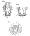
- Figure 1
- a first embodiment of a fluid injector with a valve body,
- Figure 2
- an enlargement of the valve body according to Figure 1,
- Figure 3
- a further enlargement of parts of the valve body according to Figure 2,
- Figure 4
- a second embodiment of the valve body,
- Figure 5
- the second embodiment of the valve body in a given position,
- Figure 6
- a third embodiment of the valve body and
- Figure 7
- a fourth embodiment of the valve body.
- Elements of the same design and function, that occur in different illustrations are identified by the same reference character.
- A fluid injector, that is used as a fuel injector for an internal combustion engine, comprises a housing 1, a
valve body 2, an actuator unit and a fuel connector. The fuel connector is designed to be connected to a high pressure fuel chamber of the internal combustion engine, where fuel is stored under high pressure, for example under the pressure of about 200 bar. - The housing 1 is preferably formed in a way, that there is a space to lead the fuel from the fuel connector to a fuel inlet of the valve body.
- The actuator unit is preferably arranged in the housing. The actuator unit may be of a type known to a person skilled in the art, that is suitable for that purpose. It may, for example, contain a piezoelectric actuator. However, it may alternatively contain an electromagnetic actuator, that comprises an
armature 31, asolenoid 32 and apole element 33. Areturn spring 25 is arranged and pre-loaded in such a way, that it pushes thearmature 31 away from thepole element 33 unless an electromagnetic force created by thesolenoid 32 is larger than the pre-loading force of thereturn spring 25. - The
valve body 2 comprises acartridge 21, which is fixed to the housing 1 at one of its free ends, preferably by welding, especially by laser-welding. Thecartridge 21 comprises a recess, which takes in the needle and also serves as a fluid duct. The recess takes in on one of its ends aseat plate 213, which comprises in a conically-shaped area 2131 aneedle seat 2132 for an inward-openingneedle 22. Theneedle 22 comprises aseat part 221 with a sealingarea 222, that is destined to rest on theneedle seat 2132, if theseat part 221 is pushed against theneedle seat 2132. Theneedle 22 is mechanically coupled to thearmature 31. - If the
needle 22 rests with the sealingarea 222 of itsseat part 221 in theneedle seat 2132, fluid is prevented from flowing into asack volume 2133, which is limited by respective walls of theseat plate 213 and by adisk 214, which has aninjection nozzle 215, through which the fluid can flow out of thevalve body 2 from thesack volume 2133. - The
seat part 221 comprises a cavity, which is located radially inwards and in proximity to thesealing area 222. The cavity may be formed as ablind hole 223. The blind hole can easily be manufactured by, for example, drilling. By theblind hole 223 the flexibility of the sealingarea 222 is increased. Like that micrometric deformations of theseat part 221 in thesealing area 222 are enabled if it contacts theneedle seat 2132. This improves significantly the quality of the sealing between theneedle seat 2132 and the sealingarea 222.
Alternatively the cavity may be a centrically-dished area or may be annular-shaped. - Figure 2 shows the
needle 22 in a position, where the sealingarea 222 is spaced apart from theneedle seat 2132 and fluid flows into thesack volume 2133 and from there exits the valve body through theinjection nozzle 215. - In the embodiment of the
valve body 2 of Figure 4 afiller part 226 is taken in thecavity 223 and fills up thecavity 223 except for an annular-shapedcavity 224, which is formed between a wall of the filler part and theblind hole 223. By this the free space, where fluid can flow off the cavity, which in this case is formed by the annular-shapedcavity 224, is significantly reduced. In combination with a suitable depth of the annular-shapedcavity 224 the right flexibility of theseat part 221 in order to ensure a high quality sealing between theneedle seat 2132 and the sealingarea 222 is achieved. - In an alternative embodiment the filler part may fill the
blind hole 223 also to a greater extent. In this case the material of thefiller part 226 needs to be of suitable stiffness in order to achieve the desired flexibility of theseat part 221 of theneedle 22. If the filler part has a low enough stiffness it may also fill the wholeblind hole 223. - Preferably the
filler part 226 protrudes into thesack volume 2133. By this measure the free volume, where fluid can flow into the sack volume, is reduced, which improves the hot temperature performance of the fluid injector. Thefiller part 226 may, for example, consist of metal or plastic. Plastic has the advantage that it is easy to manufacture and it may be injection-molded in an easy way. - The annular-shaped
cavity 224 has in addition the advantage, that when theneedle 22 hits with itssealing area 222 of itsseat part 221 theneedle seat 2132 theseat part 221 is bent inwards as shown in Figure 5 which reduces the volume of the annular-shapedcavity 224 and increases the hydraulic resistance for the fluid inside the annular-shapedcavity 224, which tends to flow out of the annular-shapedchamber 224 because of the pressure increase due to the impact. The flow of the fluid out from the annular-shapedcavity 224 dissipates a significant part of the kinetic energy of theneedle 22 and theseat part 221, dampening its possible bounces. - The
seat part 221 may also be spherically-shaped, which improves the sealing quality between theneedle seat 2132 and the sealingarea 222. - The spherical shape can be easily obtained by forming the
seat part 221 out of aball 228 with a hole passing through the ball, where theneedle 22 is taken in and which forms together with theneedle 22 the annular-shapedcavity 224. Theball 228 is preferably fixed to theneedle 22 by welding. In this embodiment aneedle tip 229 may protrude into thesack volume 2133. - In another embodiment of the valve body 3 (Figure 7) the
needle 22 is of an outward opening type. Thecartridge 21 comprises adisk 214 with theinjection nozzle 215 being formed in thedisk 214. Differently from the other embodiments the needle tip 229A comprises a sealing area 229B, which rests in the closed position of theneedle 22 on aneedle seat 2141 which is formed in theinjection nozzle 215 of thedisk 214. An annular-shaped cavity 229C is formed in the needle tip 229A of theneedle 22 in proximity to the sealing area 229B radially inwards and in communication with therecess 211. By this measure the flexibility of the needle tip 229A is increased and micrometric tip deformations of the needle in theneedle seat 2141 are enabled, which improves the sealing quality between theneedle seat 2141 and the sealing area 229B of theneedle 22.
Claims (10)
- Valve body with a needle (22) and a cartridge (21) with a recess (211), which takes in the needle (22) and which comprises on one of its ends a seat plate (213), that comprises a needle seat (2132) for the inward opening needle (22), with the needle (22) further comprising a seat-part (221) with a sealing area (222), that is destined to rest on the needle seat (2132), if it is pushed against the needle seat (2132), with the seat-part (221) comprising a cavity radially inwards and in proximity to the sealing area (222).
- Valve body in accordance with claim 1 with the cavity being formed as a blind hole (223).
- Valve body in accordance with one of the preceding claims with a filler part (226), that is taken in the cavity.
- Valve body in accordance with claim 3 with the filler part (226) protruding into a sack volume (2133) formed in the seat plate (213).
- Valve body in accordance with one of the claims 3 or 4, with the filler part (226) consisting of plastics.
- Valve body in accordance with one of the preceding claims with the cavity being formed in an annular shape.
- Valve body in accordance with claim 6 with part of the seat part (221) protruding into a sack volume (2133) formed in the seat plate (213).
- Valve body in accordance with one of the preceding claims with the seat part (221) being spherically shaped.
- Valve body in accordance with claim 8 with the seat part (221) being formed by a ball (228) with a hole passing through the ball (228), where the needle (22) is taken in and which forms together with the needle (22) a cavity.
- Fluid injector with a housing (1), an actuator unit and a valve body (2) in accordance with one of the preceding claims.
Priority Applications (6)
| Application Number | Priority Date | Filing Date | Title |
|---|---|---|---|
| EP04001802A EP1559903B1 (en) | 2004-01-28 | 2004-01-28 | Fuel injector with deformable needle |
| DE602004018259T DE602004018259D1 (en) | 2004-01-28 | 2004-01-28 | Injection valve with deformable needle |
| US10/597,467 US8662420B2 (en) | 2004-01-28 | 2004-12-02 | Valve body and fluid injector with a valve body |
| JP2006549936A JP2007518926A (en) | 2004-01-28 | 2004-12-02 | Fluid injector with deformable needle |
| PCT/EP2004/053219 WO2005075812A1 (en) | 2004-01-28 | 2004-12-02 | Fluid injector with deformable needle |
| CNA2004800411145A CN1906400A (en) | 2004-01-28 | 2004-12-02 | Fluid injector with deformable needle |
Applications Claiming Priority (1)
| Application Number | Priority Date | Filing Date | Title |
|---|---|---|---|
| EP04001802A EP1559903B1 (en) | 2004-01-28 | 2004-01-28 | Fuel injector with deformable needle |
Publications (2)
| Publication Number | Publication Date |
|---|---|
| EP1559903A1 true EP1559903A1 (en) | 2005-08-03 |
| EP1559903B1 EP1559903B1 (en) | 2008-12-10 |
Family
ID=34639394
Family Applications (1)
| Application Number | Title | Priority Date | Filing Date |
|---|---|---|---|
| EP04001802A Expired - Fee Related EP1559903B1 (en) | 2004-01-28 | 2004-01-28 | Fuel injector with deformable needle |
Country Status (6)
| Country | Link |
|---|---|
| US (1) | US8662420B2 (en) |
| EP (1) | EP1559903B1 (en) |
| JP (1) | JP2007518926A (en) |
| CN (1) | CN1906400A (en) |
| DE (1) | DE602004018259D1 (en) |
| WO (1) | WO2005075812A1 (en) |
Families Citing this family (2)
| Publication number | Priority date | Publication date | Assignee | Title |
|---|---|---|---|---|
| DE102006052817A1 (en) * | 2006-11-09 | 2008-05-15 | Robert Bosch Gmbh | Fuel injection valve for e.g. direct injection of fuel into combustion chamber of internal combustion engine, has valve seat body and closing body provided with rigidity-reducing element that is designed as recess i.e. circulating groove |
| EP2778386B1 (en) * | 2013-03-13 | 2016-03-09 | Delphi International Operations Luxembourg S.à r.l. | Control valve assembly and fuel injector incorporating a control valve assembly |
Citations (16)
| Publication number | Priority date | Publication date | Assignee | Title |
|---|---|---|---|---|
| DE502601C (en) * | 1926-03-31 | 1930-07-16 | Super Diesel Tractor Corp | Method and pressure device for the production of a fluid-tight seat in injection valves for internal combustion engines o. |
| DE859395C (en) * | 1943-04-11 | 1952-12-15 | Auto Union A G | Injection nozzles, in particular for internal combustion engines |
| US4007880A (en) * | 1974-12-12 | 1977-02-15 | Robert Bosch G.M.B.H. | Electromagnetic fuel injection valve |
| US4270257A (en) * | 1975-04-26 | 1981-06-02 | Ntn Toyo Bearing Co. Ltd. | Method for manufacturing a fuel injection valve |
| US4651931A (en) * | 1984-05-19 | 1987-03-24 | Robert Bosch Gmbh | Injection valve |
| US4890794A (en) * | 1987-10-05 | 1990-01-02 | Robert Bosch Gmbh | Perforated body for a fuel injection valve |
| US4907745A (en) * | 1987-07-17 | 1990-03-13 | Robert Bosch Gmbh | Fuel injection valve and method for adjusting it |
| US5090625A (en) * | 1988-06-10 | 1992-02-25 | Orbital Engine Company Proprietary Limited | Nozzles for in-cylinder fuel injection systems |
| US5551638A (en) * | 1992-02-17 | 1996-09-03 | Orbital Engine Company (Australia) Pty. Limited | Valve member for fuel injection nozzles |
| US5833142A (en) * | 1993-08-18 | 1998-11-10 | Orbital Engine Company (Australia) Pty. Limited | Fuel injector nozzles |
| US20020179742A1 (en) * | 2000-07-15 | 2002-12-05 | Fevzi Yildirim | Fuel injection valve |
| WO2003002867A1 (en) * | 2001-06-26 | 2003-01-09 | Robert Bosch Gmbh | Fuel injection valve |
| US20030057298A1 (en) * | 2000-01-08 | 2003-03-27 | Friedrich Boecking | Fuel injection valve for internal combustion engines |
| US20030155442A1 (en) * | 2000-12-22 | 2003-08-21 | Heinrich Faber | Fuel-injection valve for internal combustion engines |
| US20030173428A1 (en) * | 2001-03-28 | 2003-09-18 | Christoph Buehler | Fuel-injection valve for internal combustion engines |
| WO2003078826A1 (en) * | 2002-03-19 | 2003-09-25 | Robert Bosch Gmbh | Fuel injection valve |
Family Cites Families (5)
| Publication number | Priority date | Publication date | Assignee | Title |
|---|---|---|---|---|
| DE3029721A1 (en) * | 1980-08-06 | 1982-03-04 | Robert Bosch Gmbh, 7000 Stuttgart | FUEL INJECTION VALVE FOR INTERNAL COMBUSTION ENGINES |
| US4423842A (en) * | 1982-02-24 | 1984-01-03 | General Motors Corporation | Electromagnetic fuel injector with self aligned armature |
| DE19936942A1 (en) * | 1999-08-05 | 2001-02-08 | Bosch Gmbh Robert | Fuel injector |
| DE60044626D1 (en) * | 1999-10-06 | 2010-08-12 | Delphi Tech Holding Sarl | Fuel injection valve |
| WO2003016707A1 (en) | 2001-08-08 | 2003-02-27 | Siemens Aktiengesellschaft | Dosing device |
-
2004
- 2004-01-28 EP EP04001802A patent/EP1559903B1/en not_active Expired - Fee Related
- 2004-01-28 DE DE602004018259T patent/DE602004018259D1/en not_active Expired - Lifetime
- 2004-12-02 JP JP2006549936A patent/JP2007518926A/en not_active Withdrawn
- 2004-12-02 WO PCT/EP2004/053219 patent/WO2005075812A1/en active Application Filing
- 2004-12-02 CN CNA2004800411145A patent/CN1906400A/en active Pending
- 2004-12-02 US US10/597,467 patent/US8662420B2/en not_active Expired - Fee Related
Patent Citations (16)
| Publication number | Priority date | Publication date | Assignee | Title |
|---|---|---|---|---|
| DE502601C (en) * | 1926-03-31 | 1930-07-16 | Super Diesel Tractor Corp | Method and pressure device for the production of a fluid-tight seat in injection valves for internal combustion engines o. |
| DE859395C (en) * | 1943-04-11 | 1952-12-15 | Auto Union A G | Injection nozzles, in particular for internal combustion engines |
| US4007880A (en) * | 1974-12-12 | 1977-02-15 | Robert Bosch G.M.B.H. | Electromagnetic fuel injection valve |
| US4270257A (en) * | 1975-04-26 | 1981-06-02 | Ntn Toyo Bearing Co. Ltd. | Method for manufacturing a fuel injection valve |
| US4651931A (en) * | 1984-05-19 | 1987-03-24 | Robert Bosch Gmbh | Injection valve |
| US4907745A (en) * | 1987-07-17 | 1990-03-13 | Robert Bosch Gmbh | Fuel injection valve and method for adjusting it |
| US4890794A (en) * | 1987-10-05 | 1990-01-02 | Robert Bosch Gmbh | Perforated body for a fuel injection valve |
| US5090625A (en) * | 1988-06-10 | 1992-02-25 | Orbital Engine Company Proprietary Limited | Nozzles for in-cylinder fuel injection systems |
| US5551638A (en) * | 1992-02-17 | 1996-09-03 | Orbital Engine Company (Australia) Pty. Limited | Valve member for fuel injection nozzles |
| US5833142A (en) * | 1993-08-18 | 1998-11-10 | Orbital Engine Company (Australia) Pty. Limited | Fuel injector nozzles |
| US20030057298A1 (en) * | 2000-01-08 | 2003-03-27 | Friedrich Boecking | Fuel injection valve for internal combustion engines |
| US20020179742A1 (en) * | 2000-07-15 | 2002-12-05 | Fevzi Yildirim | Fuel injection valve |
| US20030155442A1 (en) * | 2000-12-22 | 2003-08-21 | Heinrich Faber | Fuel-injection valve for internal combustion engines |
| US20030173428A1 (en) * | 2001-03-28 | 2003-09-18 | Christoph Buehler | Fuel-injection valve for internal combustion engines |
| WO2003002867A1 (en) * | 2001-06-26 | 2003-01-09 | Robert Bosch Gmbh | Fuel injection valve |
| WO2003078826A1 (en) * | 2002-03-19 | 2003-09-25 | Robert Bosch Gmbh | Fuel injection valve |
Also Published As
| Publication number | Publication date |
|---|---|
| US20070278329A1 (en) | 2007-12-06 |
| JP2007518926A (en) | 2007-07-12 |
| DE602004018259D1 (en) | 2009-01-22 |
| CN1906400A (en) | 2007-01-31 |
| US8662420B2 (en) | 2014-03-04 |
| EP1559903B1 (en) | 2008-12-10 |
| WO2005075812A1 (en) | 2005-08-18 |
Similar Documents
| Publication | Publication Date | Title |
|---|---|---|
| EP2148082B1 (en) | Coupling arrangement for an injection valve and injection valve | |
| CN100402831C (en) | Fuel injection valve | |
| JP2006274841A (en) | Fuel injection device of internal combustion engine | |
| CN108138715B (en) | Fuel injection valve with anti-bouncing device, combustion engine and vehicle | |
| WO2006063493A1 (en) | A fuel injection nozzle | |
| EP1845254A1 (en) | Valve assembly | |
| KR20120012817A (en) | Valve assembly for an injection valve and injection valve | |
| US20050056710A1 (en) | Fuel injection valve | |
| US8172161B2 (en) | Valve body, fluid injector and process for manufacturing a valve body | |
| EP1559903A1 (en) | Fuel injector with deformable needle | |
| JP3832401B2 (en) | Fuel injection device | |
| EP2149699B1 (en) | Fuel injector | |
| US20040026541A1 (en) | Fuel injection valve | |
| KR101625587B1 (en) | Injection valve | |
| US7762478B1 (en) | High speed gasoline unit fuel injector | |
| EP1712776A1 (en) | Valve body and fluid injector with a valve body | |
| RU2002110093A (en) | Fuel injector valve | |
| EP1548272A1 (en) | Valve body and fluid injector with valve body | |
| EP1559905A1 (en) | Fluid injector with a deformable valve needle | |
| KR100719462B1 (en) | Injector for vehicle | |
| EP1794442B1 (en) | Fuel injector with vop loss resistant valve spring for emissions-compliant engine applications i | |
| EP1793120A1 (en) | Valve assembly for an injection valve | |
| EP2295787A1 (en) | Fuel Injector | |
| EP1816344A1 (en) | Valve assembly for an injection valve and injection valve | |
| EP1559907A1 (en) | Fluid injector with means to prevent rotation of the valve needle |
Legal Events
| Date | Code | Title | Description |
|---|---|---|---|
| PUAI | Public reference made under article 153(3) epc to a published international application that has entered the european phase |
Free format text: ORIGINAL CODE: 0009012 |
|
| AK | Designated contracting states |
Kind code of ref document: A1 Designated state(s): AT BE BG CH CY CZ DE DK EE ES FI FR GB GR HU IE IT LI LU MC NL PT RO SE SI SK TR |
|
| AX | Request for extension of the european patent |
Extension state: AL LT LV MK |
|
| 17P | Request for examination filed |
Effective date: 20060203 |
|
| AKX | Designation fees paid |
Designated state(s): DE FR GB IT |
|
| 17Q | First examination report despatched |
Effective date: 20060510 |
|
| GRAP | Despatch of communication of intention to grant a patent |
Free format text: ORIGINAL CODE: EPIDOSNIGR1 |
|
| GRAS | Grant fee paid |
Free format text: ORIGINAL CODE: EPIDOSNIGR3 |
|
| GRAA | (expected) grant |
Free format text: ORIGINAL CODE: 0009210 |
|
| RAP1 | Party data changed (applicant data changed or rights of an application transferred) |
Owner name: CONTINENTAL AUTOMOTIVE ITALY S.P.A. |
|
| AK | Designated contracting states |
Kind code of ref document: B1 Designated state(s): DE FR GB IT |
|
| REG | Reference to a national code |
Ref country code: GB Ref legal event code: FG4D |
|
| REF | Corresponds to: |
Ref document number: 602004018259 Country of ref document: DE Date of ref document: 20090122 Kind code of ref document: P |
|
| PLBE | No opposition filed within time limit |
Free format text: ORIGINAL CODE: 0009261 |
|
| STAA | Information on the status of an ep patent application or granted ep patent |
Free format text: STATUS: NO OPPOSITION FILED WITHIN TIME LIMIT |
|
| 26N | No opposition filed |
Effective date: 20090911 |
|
| REG | Reference to a national code |
Ref country code: FR Ref legal event code: PLFP Year of fee payment: 13 |
|
| REG | Reference to a national code |
Ref country code: FR Ref legal event code: PLFP Year of fee payment: 14 |
|
| REG | Reference to a national code |
Ref country code: FR Ref legal event code: PLFP Year of fee payment: 15 |
|
| PGFP | Annual fee paid to national office [announced via postgrant information from national office to epo] |
Ref country code: DE Payment date: 20180131 Year of fee payment: 15 |
|
| PGFP | Annual fee paid to national office [announced via postgrant information from national office to epo] |
Ref country code: IT Payment date: 20190124 Year of fee payment: 16 Ref country code: GB Payment date: 20190121 Year of fee payment: 16 Ref country code: FR Payment date: 20190123 Year of fee payment: 16 |
|
| REG | Reference to a national code |
Ref country code: DE Ref legal event code: R119 Ref document number: 602004018259 Country of ref document: DE |
|
| PG25 | Lapsed in a contracting state [announced via postgrant information from national office to epo] |
Ref country code: DE Free format text: LAPSE BECAUSE OF NON-PAYMENT OF DUE FEES Effective date: 20190801 |
|
| GBPC | Gb: european patent ceased through non-payment of renewal fee |
Effective date: 20200128 |
|
| PG25 | Lapsed in a contracting state [announced via postgrant information from national office to epo] |
Ref country code: FR Free format text: LAPSE BECAUSE OF NON-PAYMENT OF DUE FEES Effective date: 20200131 Ref country code: GB Free format text: LAPSE BECAUSE OF NON-PAYMENT OF DUE FEES Effective date: 20200128 |
|
| PG25 | Lapsed in a contracting state [announced via postgrant information from national office to epo] |
Ref country code: IT Free format text: LAPSE BECAUSE OF NON-PAYMENT OF DUE FEES Effective date: 20200128 |