EP1561190B1 - Foreign object detection system and method - Google Patents
Foreign object detection system and method Download PDFInfo
- Publication number
- EP1561190B1 EP1561190B1 EP03758631A EP03758631A EP1561190B1 EP 1561190 B1 EP1561190 B1 EP 1561190B1 EP 03758631 A EP03758631 A EP 03758631A EP 03758631 A EP03758631 A EP 03758631A EP 1561190 B1 EP1561190 B1 EP 1561190B1
- Authority
- EP
- European Patent Office
- Prior art keywords
- foreign object
- detection
- airport
- foreign
- detector modules
- Prior art date
- Legal status (The legal status is an assumption and is not a legal conclusion. Google has not performed a legal analysis and makes no representation as to the accuracy of the status listed.)
- Expired - Lifetime
Links
- 238000001514 detection method Methods 0.000 title claims abstract description 79
- 238000000034 method Methods 0.000 title claims description 9
- 238000004891 communication Methods 0.000 claims description 34
- 230000001771 impaired effect Effects 0.000 claims description 5
- 238000007689 inspection Methods 0.000 claims description 5
- 238000003384 imaging method Methods 0.000 description 22
- 230000000712 assembly Effects 0.000 description 13
- 238000000429 assembly Methods 0.000 description 13
- 230000007613 environmental effect Effects 0.000 description 13
- 238000010586 diagram Methods 0.000 description 12
- 230000001276 controlling effect Effects 0.000 description 10
- 230000003068 static effect Effects 0.000 description 8
- 238000004458 analytical method Methods 0.000 description 6
- 238000009429 electrical wiring Methods 0.000 description 6
- 238000005286 illumination Methods 0.000 description 4
- 238000010191 image analysis Methods 0.000 description 4
- 238000003708 edge detection Methods 0.000 description 3
- 230000011218 segmentation Effects 0.000 description 3
- 230000000295 complement effect Effects 0.000 description 2
- 230000000694 effects Effects 0.000 description 2
- 238000000605 extraction Methods 0.000 description 2
- 238000012935 Averaging Methods 0.000 description 1
- 230000002596 correlated effect Effects 0.000 description 1
- 230000000875 corresponding effect Effects 0.000 description 1
- 238000009795 derivation Methods 0.000 description 1
- 230000002708 enhancing effect Effects 0.000 description 1
- 238000001914 filtration Methods 0.000 description 1
- 230000001360 synchronised effect Effects 0.000 description 1
Images


Classifications
-
- G—PHYSICS
- G08—SIGNALLING
- G08G—TRAFFIC CONTROL SYSTEMS
- G08G5/00—Traffic control systems for aircraft, e.g. air-traffic control [ATC]
- G08G5/0073—Surveillance aids
- G08G5/0082—Surveillance aids for monitoring traffic from a ground station
-
- B—PERFORMING OPERATIONS; TRANSPORTING
- B64—AIRCRAFT; AVIATION; COSMONAUTICS
- B64F—GROUND OR AIRCRAFT-CARRIER-DECK INSTALLATIONS SPECIALLY ADAPTED FOR USE IN CONNECTION WITH AIRCRAFT; DESIGNING, MANUFACTURING, ASSEMBLING, CLEANING, MAINTAINING OR REPAIRING AIRCRAFT, NOT OTHERWISE PROVIDED FOR; HANDLING, TRANSPORTING, TESTING OR INSPECTING AIRCRAFT COMPONENTS, NOT OTHERWISE PROVIDED FOR
- B64F1/00—Ground or aircraft-carrier-deck installations
- B64F1/18—Visual or acoustic landing aids
-
- G—PHYSICS
- G06—COMPUTING; CALCULATING OR COUNTING
- G06T—IMAGE DATA PROCESSING OR GENERATION, IN GENERAL
- G06T7/00—Image analysis
- G06T7/0002—Inspection of images, e.g. flaw detection
-
- G—PHYSICS
- G06—COMPUTING; CALCULATING OR COUNTING
- G06T—IMAGE DATA PROCESSING OR GENERATION, IN GENERAL
- G06T7/00—Image analysis
- G06T7/0002—Inspection of images, e.g. flaw detection
- G06T7/0004—Industrial image inspection
-
- G—PHYSICS
- G06—COMPUTING; CALCULATING OR COUNTING
- G06T—IMAGE DATA PROCESSING OR GENERATION, IN GENERAL
- G06T7/00—Image analysis
- G06T7/20—Analysis of motion
- G06T7/254—Analysis of motion involving subtraction of images
-
- G—PHYSICS
- G06—COMPUTING; CALCULATING OR COUNTING
- G06T—IMAGE DATA PROCESSING OR GENERATION, IN GENERAL
- G06T7/00—Image analysis
- G06T7/20—Analysis of motion
- G06T7/292—Multi-camera tracking
-
- G—PHYSICS
- G08—SIGNALLING
- G08G—TRAFFIC CONTROL SYSTEMS
- G08G5/00—Traffic control systems for aircraft, e.g. air-traffic control [ATC]
- G08G5/0017—Arrangements for implementing traffic-related aircraft activities, e.g. arrangements for generating, displaying, acquiring or managing traffic information
- G08G5/0026—Arrangements for implementing traffic-related aircraft activities, e.g. arrangements for generating, displaying, acquiring or managing traffic information located on the ground
-
- G—PHYSICS
- G08—SIGNALLING
- G08G—TRAFFIC CONTROL SYSTEMS
- G08G5/00—Traffic control systems for aircraft, e.g. air-traffic control [ATC]
- G08G5/04—Anti-collision systems
- G08G5/045—Navigation or guidance aids, e.g. determination of anti-collision manoeuvers
-
- G—PHYSICS
- G08—SIGNALLING
- G08G—TRAFFIC CONTROL SYSTEMS
- G08G5/00—Traffic control systems for aircraft, e.g. air-traffic control [ATC]
- G08G5/06—Traffic control systems for aircraft, e.g. air-traffic control [ATC] for control when on the ground
- G08G5/065—Navigation or guidance aids, e.g. for taxiing or rolling
-
- H—ELECTRICITY
- H04—ELECTRIC COMMUNICATION TECHNIQUE
- H04N—PICTORIAL COMMUNICATION, e.g. TELEVISION
- H04N7/00—Television systems
- H04N7/18—Closed-circuit television [CCTV] systems, i.e. systems in which the video signal is not broadcast
- H04N7/181—Closed-circuit television [CCTV] systems, i.e. systems in which the video signal is not broadcast for receiving images from a plurality of remote sources
-
- G—PHYSICS
- G06—COMPUTING; CALCULATING OR COUNTING
- G06T—IMAGE DATA PROCESSING OR GENERATION, IN GENERAL
- G06T2207/00—Indexing scheme for image analysis or image enhancement
- G06T2207/30—Subject of image; Context of image processing
- G06T2207/30108—Industrial image inspection
-
- G—PHYSICS
- G06—COMPUTING; CALCULATING OR COUNTING
- G06T—IMAGE DATA PROCESSING OR GENERATION, IN GENERAL
- G06T2207/00—Indexing scheme for image analysis or image enhancement
- G06T2207/30—Subject of image; Context of image processing
- G06T2207/30236—Traffic on road, railway or crossing
Definitions
- the present invention relates to aircraft safety generally and more particularly to detection and warning of the presence of foreign objects on airport travel surfaces.
- De101 04 950 describes a traffic routing device including navigation lights and sensors connected to the same power supply and control channel.
- Ep 0 613 111 describes a system according to the precharacterising portion of claim 1.
- the present invention seeks to provide a highly efficient and cost-effective system and methodology for detection warning of the presence of foreign objects on airport travel surfaces.
- the airport travel surfaces include at least one taxiway and at least one runway and the system employs at least some existing electrical power infrastructure associated with existing runway and taxiway lighting fixtures.
- the plurality of foreign object detector modules may commnunicate with a computer system which includes an operator console operative to provide a foreign object presence alarm and an image of the foreign object to an operator.
- the high speed detection output analyzer is located in the vicinity of the operator console.
- the system also includes a laser pointer associated with at least one of the plurality of foreign object detector modules to assist in on-site inspections.
- each of the plurality of foreign object detector modules incorporates at least one foreign object sensor module and a local processing module which receives an output from the at least one foreign object sensor module and provides the detection output including at least an initial determination of whether a foreign object is present.
- the local processing module includes multiple sensor correlation software providing correlation between the output from multiple ones of the at least one foreign object sensor module in the detector module.
- each of the plurality of foreign object detector modules incorporates at least one foreign object sensor module which provides the detection output to the high speed detection output analyzer which is remotely located with respect thereto.
- the high speed detection output analyzer includes multiple sensor correlation software providing correlation between the detection output from multiple ones of the at least one foreign object sensor module in individual ones of the plurality of detector modules.
- the high speed detection output analyzer includes multiple detector correlation software providing correlation between the detection output from multiple ones of the at least one foreign object sensor module in multiple ones of the plurality of detector modules.
- each of the plurality of foreign object detector modules includes at least one camera and at least one illuminator.
- the at least one illuminator includes a fixed field illuminator.
- the at least one illuminator includes a scanning illuminator.
- the at least one camera includes a fixed field camera.
- the at least one camera includes a scanning camera.
- the at least one camera includes a zoom functionality.
- each of the plurality of foreign object detector modules also has associated therewith at least one of a light level sensor, a vibration sensor and a temperature sensor.
- the system also includes controlling software which includes a communication module which handles communications with the plurality of detector modules via a communications network, and management software which interfaces with the communications module.
- the management software interfaces with existing airport control systems, and with a database, a graphical user interface having image manipulation capability and an alarm indicator.
- the management software also interfaces with multiple detector correlation software, which provides information based on outputs from multiple ones of the plurality of detector modules.
- the high speed detection output analyzer provides at least first and second modes of operation, the first mode of operation being employed under conditions of normal visibility and the second mode of operation being employed under conditions of impaired visibility. Additionally, the high speed detection output analyzer provides differing levels of signal/noise filtering for operation in the first and second modes of operation.
- the high speed detection output analyzer software employs at least one of frame segmentation, gray level histogram comparison and edge detection.
- the frame segmentation and gray level histogram comparison are employed to generate gray scale difference maps highlighting suspected foreign objects.
- the edge detection is employed to generate edge extraction difference maps highlighting suspected foreign objects.
- the high speed detection output analyzer is operative to provide the high speed output indication of foreign object presence within less than 1 minute.
- the system also includes a storage unit, for storing the detection outputs in a time sequence.
- the high speed detection output analyzer is operative to compare the detection outputs to the stored detection outputs.
- the plurality of foreign object detector modules have at least partially overlapping fields of view.
- the plurality of foreign object detector modules include a plurality of cameras, and the cameras have at least partially overlapping fields of view.
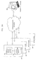
- FIG. 1 is a simplified pictorial illustration of a system for detection of foreign objects on airport travel surfaces constructed and operative in accordance with a preferred embodiment of the present invention.
- the system is preferably incorporated into existing infrastructure of an airport having various airport travel surfaces, such as a taxiway 100 and a runway 102.
- the present invention may be applicable as well to other aircraft travel surfaces such as aprons (not shown).
- the system employs some or all of existing runway and taxiway lighting fixtures 104 and may employ electrical power supplies and conduits (not shown) associated therewith for both power and data communication.
- the system is also useful with individually solar powered lighting fixtures.
- some, but not all, of the existing lighting fixtures are equipped with foreign object detector modules 106 which enable detection of foreign objects on a runway or taxiway.
- Detector modules 106 preferably communicate, through a controlling software module described hereinbelow with reference to Fig. 5 , with an operator console 107, which preferably forms part of a computer system 108, which may be any conventional networked or standalone computer system.
- Operator console 107 preferably provides a foreign object presence alarm and an image of a detected foreign object 109 to an operator. The operator is thus enabled to make an abort decision as appropriate and is provided information relating to the location of the detected foreign object 109 in order to enable an on-site inspection to be carried out quickly and efficiently.
- a laser pointer 110 may be incorporated in the detector module 106 to assist in on-site inspections.
- each detector module 106 ( Fig. 1 ) comprises a foreign object sensor module 120, comprising one or more sensors, such as cameras, and related devices as described hereinbelow with reference to Figs. 6A-6C , and a local processing module 122 which receives at least one output from the sensor module 120 and provides at least an initial determination of whether a foreign object is present.
- Local processing module 122 preferably comprises a high speed detection output analyzer as described hereinbelow with reference to Figs.
- Each detector module 106 communicates, in a wired or wireless manner as most appropriate, via a communications network 124, such as a LAN, with the computer system 108 ( Fig. 1 ).
- a communications network 124 such as a LAN
- each detector module 106 ( Fig. 1 ) comprises a foreign object sensor module 130, comprising one or more sensors, such as cameras, and related devices as described hereinbelow with reference to Figs. 6A-6C .
- Each detector module 106 communicates, in a wired or wireless manner as most appropriate, via a communications network 132, such as a LAN, with the computer system 108 ( Fig. 1 ), which includes a central processing module 134, which provides at least an initial determination of whether a foreign object is present.
- Central processing module 134 preferably comprises a high speed detection output analyzer as described hereinbelow with reference to Figs. 9A-9H and Figs. 9K-9L , which preferably also includes a multiple sensor correlation algorithm as described hereinbelow with reference to Fig. 9I and a multiple detector correlation algorithm as described hereinbelow with reference to Fig. 9J .
- FIG. 3 is a simplified block diagram illustration of a combined system of the type shown in Fig. 1 , which incorporates elements of at least one of the types shown in Figs. 2A and 2B .
- multiple groups of detector modules 106 may communicate via multiple computer networks, through management software described hereinbelow with reference to Fig. 5 , with a computer system 140, such as computer system 108 of Fig. 1 .
- a computer system 140 such as computer system 108 of Fig. 1 .
- first and second groups 142 and 144 of detector modules 106 ( Fig. 1 ) of the type shown in Fig.
- FIG. 2A may communicate via respective LANs 146 and 148, while third and fourth groups 150 and 152 of detector modules 106 ( Fig. 1 ), of the type shown in Fig. 2B , may communicate via respective LANs 154 and 158, with computer system 140.
- FIG. 4A is a simplified block diagram illustration of a detector module forming part of the system of Fig. 2A .
- an output signal from camera 214 is preferably received by a frame grabber 230 which outputs to digital signal processing circuitry 232, which performs image analysis on the output of camera 214.
- Digital signal processing circuitry 232 preferably comprises a high speed detection output analyzer as described hereinbelow with reference to Figs. 9A-9H and 9K-9L , which also preferably includes a multiple sensor correlation algorithm as described hereinbelow with reference to Fig. 9I .
- a controller computer 234 receives an output from digital signal processing circuitry 232 and may also receive an output from one or more environmental sensors such as sensors 318, 319 and 320 ( Fig. 6A ). Controller computer 234 also provides control outputs to illuminators 212, cameras 214, laser pointers 216 and other elements described hereinabove with reference to Fig. 4A .
- a communications module 236 interfaces with controller computer 234 and provides data communications via communications network 124 ( Fig. 2A ), such as a LAN, with computer system 108 ( Fig. 1 ). It is appreciated that the communications may be wired and/or wireless and may employ the existing wiring connection 304 to lamp 308 ( Fig. 6A ).
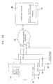
- Fig. 4B is a simplified block diagram illustration of a central processing module forming part of the system of Fig. 2B .
- the central processing module preferably comprises a server 240 which receives via communications network 132 ( Fig. 2B ), such as a LAN, output signals from a plurality of foreign object detector modules 106 ( Fig. 2B ) which include sensor modules 130 ( Fig. 2B ) and preferably provides them to a central processing module 242, which preferably comprises parallel processors with the capacity to process all of the output signals in real time.
- Central processing module 242 preferably comprises a high speed detection output analyzer as described hereinbelow with reference to Figs.
- Central processing module 242 preferably communicates, through management software described hereinbelow with reference to Fig. 5 , with operator console 107 ( Fig. 1 ) to provide an indication of whether a foreign object is present.
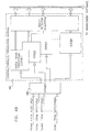
- Fig. 5 is a simplified block diagram illustration of a controlling software module forming part of the computer system in accordance with the embodiment of Fig. 2A .
- the controlling software module is preferably installed in computer system 108 ( Fig. 1 ) and comprises a communication module 250 which handles the communications with the plurality of detector modules 106 ( Fig. 2A ) via communications network 124 ( Fig. 2A ).
- Communication module 250 interfaces with management software 252 which, in turn, interfaces with a database 254, with a graphical user interface 256 having image manipulation capability provided by software, such as ADOBE ® PHOTOSHOP ® , and with an alarm indicator 258. Additionally, communication module 250 or management software 252 may interface with existing airport control systems.
- the management software 252 may also interface with a multiple detector correlation algorithm 260, a preferred embodiment of which is described in reference to Fig. 9J hereinbelow, which correlates outputs received from multiple detector modules 106 ( Fig. 2A ).
- a controlling software module similar to the controlling software module of Fig. 5 may form part of the embodiment described in reference to Figs. 2B and 4B .
- the management software 252 communicates via the communication module 250 with the central processing module 242 of Fig. 4B and does not interface with multiple detector correlation algorithm 260, since this functionality is incorporated into central processing module 242.
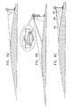
- FIGS. 6A , 6B and 6C are simplified pictorial illustrations of three alternative sensor or sensor/processor modules mounted on existing lighting supports useful in the invention of Figs. 1 - 5 .
- FIG. 6A is a simplified pictorial illustration of a preferred embodiment of a detector module forming part of the system of Fig. 2A .
- an existing airport lighting assembly 300 including a base 302 having an underground electrical wiring connection 304, a support shaft 306 and a lamp 308 may provide a platform for the detector module 309.
- a support surface 310 is mounted onto shaft 306 below lamp 308.
- Mounted onto support surface 310 there are preferably provided a plurality of static imaging assemblies 311, each preferably comprising an illuminator 312 and a camera 314.
- Camera 314 is preferably equipped with optics 315 including, inter alia, a near IR filter which is employed during daylight operation when illuminator 312 is not employed.
- One or more of the static imaging assemblies 311 may also comprise a selectably directable laser pointer 316 for indicating the location of a suspected foreign object.
- one or more scanning imaging assemblies may be employed instead of static imaging assemblies.
- One or more environmental sensors such as a light level sensor 318, a vibration sensor 319 and a temperature sensor 320, may also be mounted on support surface 310.
- illuminators 312, cameras 314 and environmental sensors are electrically connected to a local processor and communication module 322 which provides electrical power for operation and preferably also provides two-way data communication for controlling the operation of the illuminators 312, cameras 314, optics 315 and laser pointers 316 as well as processing image data from cameras 314, including performing initial image analysis thereon and providing foreign object detection output signals and environmental sensor signals via communications network 124 ( Fig. 2A ), such as a LAN, to computer system 108 ( Fig. 1 ).
- communications network 124 Fig. 2A
- communications network 124 such as a LAN
- electrical power supplied to lamp 308 via wiring 304 is employed to power the detector module and the various elements described hereinabove.
- a rechargeable battery 323 is provided to store electrical power during times that lamp 308 is illuminated and to enable such stored electrical power to be used during all other times for powering the detector module and the various elements described hereinabove.
- the static imaging assemblies 311 are enclosed within a suitable environmental enclosure 324 which includes portions that are transparent to light as required by the illuminators 312, cameras 314 and laser pointers 316.
- the detector module of Fig. 6A may also be useful in the embodiment of Fig. 2B .
- the local processor and communication module 322 does not provide local image processing.
- any suitable number of cameras 314, illuminators 312 and laser pointers 316 may be included in a detector module. It is also appreciated that the base 302 having underground electrical wiring connection 304, may be replaced by an above-ground support and wiring connection.
- FIG. 6B is a simplified pictorial illustration of a preferred embodiment of a detector module forming part of the system of Fig. 2A .
- an existing airport lighting assembly 350 including a base 352 having an underground electrical wiring connection 354, a support shaft 356 and a lamp 358 may provide a platform for the detector module.
- a support bracket 360 is mounted onto shaft 356 below lamp 358.
- a plurality of static imaging assemblies 362 each preferably comprising at least one illuminator 363 and a pair of cameras 364 and 365, preferably arranged in stacked relationship.
- This stacked relationship provides different elevations for cameras 364 and 365, providing complementary fields of view as shown in Figs. 7B and 8B and described hereinbelow in reference thereto.
- cameras 364 and 365 may be arranged side by side, having different elevational tilts to provide these complementary fields of view.
- Cameras 364 and 365 are preferably equipped with optics (not shown) including, inter alia, a near IR filter which is employed during daylight operation when illuminator 363 is not employed.
- a selectably directable laser pointer 366 Disposed within enclosure 361 there is preferably provided a selectably directable laser pointer 366 for indicating the location of a suspect foreign object.
- one or more scanning imaging assemblies may be employed instead of static imaging assemblies.
- One or more environmental sensors such as a light level sensor 368, a vibration sensor 369 and a temperature sensor 370, may also be mounted on support bracket 360.
- illuminators 363, cameras 364 & 365 and environmental sensors are electrically connected to a local processor and communication module 372 which provides electrical power for operation and preferably also provides two-way data communication for controlling the operation of the illuminators 363, cameras 364 & 365 and laser pointers 366 as well as processing image data from cameras 364 & 365, including performing initial image analysis thereon and providing foreign object detection output signals and environmental sensor signals via communications network 124 ( Fig. 2A ), such as a LAN, to computer system 108 ( Fig. 1 ).
- communications network 124 Fig. 2A
- a LAN such as a LAN
- electrical power supplied to lamp 358 via wiring 354 is employed to power the detector module and the various elements described hereinabove.
- a rechargeable battery 373 is provided to store electrical power during times that lamp 358 is illuminated and to enable such stored electrical power to be used during all other times for powering the detector module and the various elements described hereinabove.
- the detector module of Fig. 6B may also be useful in the embodiment of Fig. 2B .
- the local processor and communication module 372 does not provide local image processing.
- any suitable number of cameras 364 & 365, illuminators 362 and laser pointers 366 may be included in a detector module. It is also appreciated that the base 352 having underground electrical wiring connection 354, may be replaced by an above-ground support and wiring connection.
- FIG. 6C is a simplified pictorial illustration of a preferred embodiment of a detector module forming part of the system of Fig. 2A .
- an existing airport lighting assembly 400 including a base 402 having an underground electrical wiring connection 404, a support shaft 406 and a lamp 408 may provide a platform for the detector module.
- a support surface 410 is mounted onto shaft 406 below lamp 408.
- Mounted onto support surface 410 there are preferably provided one or more scanning imaging assemblies 411, each preferably comprising an illuminator 412 and a scanning camera 414.
- Camera 414 is preferably equipped with optics 415 including, inter alia, a near IR filter which is employed during daylight operation when illuminator 412 is not employed.
- one or more selectably directable laser pointers 416 for indicating the location of a suspect foreign object.
- the laser pointer 416 may be included in one or more of the scanning imaging assemblies 411.
- One or more environmental sensors such as a light level sensor 418, a vibration sensor 419 and a temperature sensor 420, may also be mounted on support surface 410.
- a scanning illuminator 422 is mounted adjacent the base 402 to direct illumination parallel to and just above an aircraft travel surface, typically up to 2 - 3 cm above the surface. This illumination is designed to illuminate foreign objects on the aircraft travel surface without generally illuminating the travel surface itself, thus greatly increasing contrast.
- illuminators 412 & 422 cameras 414 and environmental sensors, such as sensors 418, 419 and 420, are electrically connected to a local processor and communication module 423 which provides electrical power for operation and preferably also provides two-way data communication for controlling the operation of the illuminators 412 & 422, cameras 414 and laser pointers 416 as well as processing image data from cameras 414, including performing initial image analysis thereon and providing foreign object detection output signals and environmental sensor signals via communications network 124 ( Fig. 2A ), such as a LAN, to computer system 108 ( Fig. 1 ).
- communications network 124 Fig. 2A
- a LAN such as a LAN
- electrical power supplied to lamp 408 via wiring 404 is employed to power the detector module and the various elements described hereinabove.
- a rechargeable battery 424 is provided to store electrical power during times that lamp 408 is illuminated and to enable such stored electrical power to be used during all other times for powering the detector module and the various elements described hereinabove.
- the scanning imaging assemblies 411 are enclosed within a suitable environmental enclosure 425 and the scanning illuminator 422 is enclosed within a suitable environmental enclosure 426.
- Enclosures 425 and 426 include portions that are transparent to light as required by the illuminators 412 & 422, cameras 414 and laser pointers 416.
- At least one scanning imaging assembly 411 is provided with zoom capabilities for enhancing resolution.
- the detector module of Fig. 6C may also be useful in the embodiment of Fig. 2B .
- the local processor and communication module 423 does not provide local image processing.
- any suitable number of cameras 414, illuminators 412 & 422 and laser pointers 416 may be included in a detector module. It is also appreciated that the base 402 having underground electrical wiring connection 404, may be replaced by an above-ground support and wiring connection.
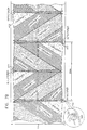
- FIGs. 7A , 7B and 7C are simplified illustrations of the azimuthal extent of protected areas provided by an array of sensors of the types shown respectively in Figs. 6A , 6B and 6C .
- Figs. 7A - 7C illustrate an example of use of the invention on a runway having a width of 60 meters, where detector modules are deployed on both sides of the runway every 100 meters in Figs. 7A and 7C , and every 200 meters in Fig. 7B . It is assumed that the runway surface is inclined downwardly towards its side edges for drainage purposes.
- each detector module 309 of Fig. 6A designated here by reference numeral 450 and having three static imaging assemblies 311 ( Fig. 6A ) typically at an elevation of 50 cm above the runway, provides slightly less than 180 degree overall coverage of one side of the runway, each imaging assembly 311 providing 60 degree coverage which slightly overlaps with that provided by an adjacent imaging assembly 311.
- each of detectors 1, 2 and 3 comprise three cameras, where the fields of view of the three cameras of detector 1 are designated as camera #1 - 1, camera #1 - 2 and camera #1 - 3. Similar designations are used for the cameras of detectors 2 and 3, as well as the field of view of one of the cameras of detector 4 (not shown), which is designated camera #4 - 1.
- each detector module of Fig. 6B designated here by reference numeral 452 and having two static imaging assemblies 362 ( Fig. 6B ), each including first and second mutually stacked cameras 364 & 365, typically at elevations of approximately 80 cm above the runway, provides slightly less than 180 degree overall coverage of one side of the runway, each imaging assembly 362 providing 90 degree coverage which slightly overlaps with that provided by an adjacent imaging assembly 362.
- lower cameras 365 have fields of view which are located relatively close to the edge of the runway, while higher cameras 364 have fields of view which slightly overlap the fields of view of cameras 365 and extend beyond the center of the runway. It is appreciated that even though the illustrated embodiment shows cameras 364 and 365 stacked one on top of the other, that they may also be situated side by side, with different elevation angles.
- each of detectors 1, 2, 3 and 4 comprise two pairs of two cameras, where the fields of view of the four cameras of detector 1 are designated as camera #1 - 1, camera #1 - 2, camera #1 - 3 and camera #1 - 4. Similar designations are used for the cameras of detectors 2, 3 and 4.
- each detector module of Fig. 6C designated here by reference numeral 454 and having at least one scanning imaging assembly 411 ( Fig. 6C ) typically at an elevation of 50 cm above the runway, provides 180 degree overall coverage of one side of the runway.
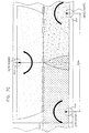
- FIGs. 8A, 8B and 8C are simplified illustrations of the elevational extent of protected areas provided by an array of sensors of the types shown respectively in Figs. 6A , 6B and 6C . It is appreciated that Figs. 8A - 8C are not drawn to scale in order to emphasize the effect of the incline of the runway from its center to its sides, which is practice is about 2%.
- Fig. 8A illustrates that in the illustrated example, the field of view of imaging assembly 311 ( Fig. 6A ) extends generally to the center of the runway.
- Fig. 8B illustrates that in the illustrated example, the field of view of imaging assembly 362 ( Fig. 6B ) partly extends beyond the center of the runway.
- Fig. 8B also shows that lower cameras 365 ( Fig. 6B ) have fields of view which are located relatively close to the edge of the runway, while higher cameras 364 ( Fig. 6B ) have fields of view which slightly overlap the fields of view of cameras 365 ( Fig. 6B ) and extend beyond the center of the runway.
- Fig. 8C illustrates that in the illustrated example, the field of view of imaging assembly 411 ( Fig. 6C ) extends generally to the center of the runway.
- Fig. 8C also shows the effect of a zoom in function providing a narrower, higher resolution, field of view 460 than the zoom out function, which scans fields of view 460 and 46
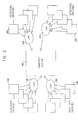
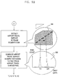
- FIGs. 9A - 9L are a simplified flowchart illustrating the operation of a high speed detection output analyzer forming a portion of a system for detection of foreign objects on airport travel surfaces in accordance with a preferred embodiment of the present invention.
- operation of the high speed detection output analyzer forming a portion of the system for detection of foreign objects on airport travel surfaces in accordance with a preferred embodiment of the present invention may begin with receipt of a light level indication, such as from light level sensor 318 in the embodiment of Fig. 6A , light level sensor 368 in the embodiment of Fig. 6B or light level sensor 418 in the embodiment of Fig. 6C . Based on the light level, day (normal visibility) or night (impaired visibility) operation is indicated.
- a light level indication such as from light level sensor 318 in the embodiment of Fig. 6A , light level sensor 368 in the embodiment of Fig. 6B or light level sensor 418 in the embodiment of Fig. 6C . Based on the light level, day (normal visibility) or night (impaired visibility) operation is indicated.
- each detector module such as detector modules 106 ( Figs. 1 , 2A & 2B ) and the detector modules described hereinabove in connection with Figs. 6A - 6C , captures at least one frame in its field of view.
- the analyzer processes frame 502 according to the single frame detection algorithm described hereinbelow in reference to Figs. 9B - 9F .
- the analyzer processes frame 502 according to the change detection algorithm described hereinbelow in reference to Figs. 9G - 9H and not falling whithin the scope of this invention
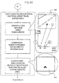
- FIG. 9B extraction of an airport travel surface, preferably by frame segmentation, takes place, yielding an image showing only the aircraft travel surface, here designated by reference numeral 504 in Fig. 9B .
- a histogram or other suitable representation of the distribution of grey-level pixels on the aircraft travel surface is then preferably generated in order to determine a typical airport travel surface pixel grey level.
- An example of such a histogram is here designated by reference numeral 506.
- Suspect areas on the aircraft travel surface are then located by finding non-typical airport travel surface pixels. This is preferably accomplished, as shown in Fig. 9C , by generating local histograms by employing a running window as illustrated at reference numeral 508. Each local histogram is compared with an expected value and a map of suspect areas is generated based on differences between local histogram values and expected histogram values. An example of such a map is designated by reference numeral 510.
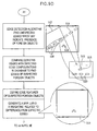
- Fig. 9D it is seen that edge detection is carried out on frame 502 ( Fig. 9A ) in order to find unexpected edges which may indicate the presence of foreign objects. Examples of detected edges are indicated by reference numerals 512 and 514. The detected edges are compared with corresponding expected edge configurations, here designated by reference numerals 513 and 515, stored in a database which may or may not be local to the detector module. Additionally, the system analyzes detected edges for relationships between edges or edge enclosed areas, such as edge enclosed areas 516, which together match expected edge configuration 517. It is noted that the edge 518, which corresponds to a foreign object, does not have a matching configuration in the database.
- a map here designated by reference numeral 519, is generated to indicate the location of the non-matched, suspect detected edge and the extent to which the suspect detected edge differs from the matching configuration in the database.
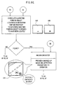
- Fig. 9E it is seen that the results of the parallel processes described above in Figs. 9B - 9C and 9D respectively are correlated in order to determine whether a foreign object is deemed to have been located. This is preferably carried out by comparing a histogram map here designated by reference numeral 520 with an edge map, here designated by reference numeral 522.
- a message is sent to a human operator through any suitable medium or media and a "marked up" version of frame 502 ( Fig. 9A ), here designated by reference numeral 524, emphasizing the location of the foreign object and providing location information, is displayed for the operator.
- a foreign object designator such as a laser pointer 110 ( Fig. 1 ) may be directed at the foreign object, as illustrated at reference numeral 526.
- the frame 502 ( Fig. 9A ) and the data generated relative thereto as described hereinabove, together with a global histogram of frame 502 ( Fig. 9A ), here indicated by reference numeral 528, are stored in a database, which may or may not be local to a given detector module.
- the stored information may be used as a base image for later comparison. It may be used together with multiple stored based images, which are preferably historically deweighted.
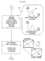
- a global histogram is generated for the current frame, as designated by reference numeral 530 and this global histogram is compared with one or more stored global histograms of preceding frames, preferably employing histogram equalization, as illustrated at reference numeral 532.
- the current frame and the base frame images are brought into registration and compared, as illustrated at reference numeral 534, to indicate changes therebetween and a difference map, designated by reference numeral 536, is produced.
- the difference map is thresholded, to render a thresholded difference map, as indicated by reference numeral 538. If peaks remain in the thresholded difference map a multi-sensor analysis is conducted, as indicated in Fig. 9I .
- the multi-sensor analysis is carried out in two stages, initially employing outputs of sensors, such as cameras, on a single detector module and thereafter on outputs of sensors, such as cameras, on multiple detector modules.
- any other suitable multi-sensor analysis regime may be employed.
- suspected foreign object information is received from multiple sensors, such as cameras 314, in detector module 309, in the embodiment of Fig. 6A .
- This information preferably includes size, shape and associated gray levels of the suspected foreign object detected, and location information within the field of view of the sensor.
- the global histogram map 530 of Fig. 9G and the difference map 536 of Fig. 9H may also be included in the information received.
- This information from multiple sensors is considered together and compared with stored information which helps to distinguish detected patterns extending over the fields of view 540 of multiple sensors, such as skid marks 542, which do not constitute foreign objects, from an actual foreign object 544.
- suspected foreign object information is received from multiple sensors, such as cameras, in multiple detector modules.
- This information preferably includes size, shape and associated gray levels of the suspected foreign object detected, and location information within the field of view of the detector. Additionally, the global histogram map 530 of Fig. 9G and the difference map 536 of Fig. 9H may also be included in the information received.
- This information from multiple detectors is considered together and compared with stored information which helps to distinguish detected patterns extending over the fields of view 550 of multiple sensors, such as cameras, on multiple detector modules 552, such as slush 554 or a moving vehicle, which do not constitute foreign objects, from an actual foreign object 556.
- Fig. 9K illustrates operation in an impaired visibility environment. If fixed illumination is employed, multiple images are captured at multiple times and combined, for example by averaging, to provide a combined noise reduced frame 560 for analysis.
- the frames 560 or 562 may then be processed for further signal to noise enhancement and are then processed as described hereinabove for frames, such as frame 502, captured during the day. It is appreciated that frames captured under impaired visibility conditions may be analyzed entirely or partially separately from frames captured under full visibility conditions.
Abstract
Description
- The present invention relates to aircraft safety generally and more particularly to detection and warning of the presence of foreign objects on airport travel surfaces.
- There exist in the patent literature various proposals for detection and warning of the presence of foreign objects on airport travel surfaces. The following patent documents are believed to represent the current state of the art:
- United States Published Patent Applications
US 2002/0080046A1 ;200210109625 A1 2002/0093433 A1 . - Additionally,
U.S. Patent 6,064,429 deals with the detection of foreign objects in a general sense. - De101 04 950 describes a traffic routing device including navigation lights and sensors connected to the same power supply and control channel.
Ep 0 613 111 describes a system according to the precharacterising portion ofclaim 1. - The present invention seeks to provide a highly efficient and cost-effective system and methodology for detection warning of the presence of foreign objects on airport travel surfaces.
- There is thus provided in accordance with a preferred embodiment of the present invention a system for detection of foreign objects on airport travel surfaces as defined in
claim 1. - There is further provided in accordance with yet another preferred embodiment of the present invention a method for detection of foreign objects on airport travel surfaces as defined in claim 16.
- Preferably, the airport travel surfaces include at least one taxiway and at least one runway and the system employs at least some existing electrical power infrastructure associated with existing runway and taxiway lighting fixtures.
- Additionally, the plurality of foreign object detector modules may commnunicate with a computer system which includes an operator console operative to provide a foreign object presence alarm and an image of the foreign object to an operator. Preferably, the high speed detection output analyzer is located in the vicinity of the operator console. Preferably, the system also includes a laser pointer associated with at least one of the plurality of foreign object detector modules to assist in on-site inspections.
- In accordance with another preferred embodiment of the present invention each of the plurality of foreign object detector modules incorporates at least one foreign object sensor module and a local processing module which receives an output from the at least one foreign object sensor module and provides the detection output including at least an initial determination of whether a foreign object is present. Preferably, the local processing module includes multiple sensor correlation software providing correlation between the output from multiple ones of the at least one foreign object sensor module in the detector module.
- Alternatively, each of the plurality of foreign object detector modules incorporates at least one foreign object sensor module which provides the detection output to the high speed detection output analyzer which is remotely located with respect thereto. Preferably, the high speed detection output analyzer includes multiple sensor correlation software providing correlation between the detection output from multiple ones of the at least one foreign object sensor module in individual ones of the plurality of detector modules. Additionally, the high speed detection output analyzer includes multiple detector correlation software providing correlation between the detection output from multiple ones of the at least one foreign object sensor module in multiple ones of the plurality of detector modules.
- In accordance with yet another preferred embodiment, each of the plurality of foreign object detector modules includes at least one camera and at least one illuminator. Preferably, the at least one illuminator includes a fixed field illuminator. Additionally or alternatively, the at least one illuminator includes a scanning illuminator. In accordance with another preferred embodiment, the at least one camera includes a fixed field camera. Alternatively or additionally, the at least one camera includes a scanning camera. Preferably, the at least one camera includes a zoom functionality.
- Additionally, each of the plurality of foreign object detector modules also has associated therewith at least one of a light level sensor, a vibration sensor and a temperature sensor.
- In accordance with a preferred embodiment of the present invention, the system also includes controlling software which includes a communication module which handles communications with the plurality of detector modules via a communications network, and management software which interfaces with the communications module. Preferably, the management software interfaces with existing airport control systems, and with a database, a graphical user interface having image manipulation capability and an alarm indicator. Additionally or alternatively, the management software also interfaces with multiple detector correlation software, which provides information based on outputs from multiple ones of the plurality of detector modules.
- Preferably, the high speed detection output analyzer provides at least first and second modes of operation, the first mode of operation being employed under conditions of normal visibility and the second mode of operation being employed under conditions of impaired visibility. Additionally, the high speed detection output analyzer provides differing levels of signal/noise filtering for operation in the first and second modes of operation.
- Additionally or alternatively, the high speed detection output analyzer software employs at least one of frame segmentation, gray level histogram comparison and edge detection. Preferably, the frame segmentation and gray level histogram comparison are employed to generate gray scale difference maps highlighting suspected foreign objects. Additionally, the edge detection is employed to generate edge extraction difference maps highlighting suspected foreign objects.
- Preferably, the high speed detection output analyzer is operative to provide the high speed output indication of foreign object presence within less than 1 minute.
- Preferably, the system also includes a storage unit, for storing the detection outputs in a time sequence. Additionally, the high speed detection output analyzer is operative to compare the detection outputs to the stored detection outputs.
- Preferably, the plurality of foreign object detector modules have at least partially overlapping fields of view. Additionally or alternatively, the plurality of foreign object detector modules include a plurality of cameras, and the cameras have at least partially overlapping fields of view.
- The present invention will be understood more fully from the following detailed description, taken in conjunction with the drawings in which:
-
Fig. 1 is a simplified pictorial illustration of a system for detection of foreign objects on airport travel surfaces constructed and operative in accordance with a preferred embodiment of the present invention; -
Fig. 2A is a simplified block diagram illustration of the system ofFig. 1 in accordance with one preferred embodiment of the present invention; -
Fig. 2B is a simplified block diagram illustration of the system ofFig. 1 in accordance with another preferred embodiment of the present invention; -
Fig. 3 is a simplified block diagram illustration of a combined system of the type shown inFig. 1 , which incorporates elements of at least one of the types shown inFigs. 2A and2B ; -
Fig. 4A is a simplified block diagram illustration of a detector module forming part of the system ofFig. 2A ; -
Fig. 4B is a simplified block diagram illustration of a central processor module forming part of the system ofFig. 2B ; -
Fig. 5 is a simplified block diagram illustration of a controlling software module, forming part of the computer system in accordance with the embodiment ofFig. 2A ; -
Figs. 6A ,6B and6C are simplified pictorial illustrations of three alternative sensor or sensor/processor modules mounted on existing lighting supports useful in the invention ofFigs. 1 - 5 ; -
Figs. 7A ,7B and7C are simplified illustrations of the azimuthal extent of protected areas provided by an array of sensors of the types shown respectively inFigs. 6A ,6B and6C ; -
Figs. 8A, 8B and 8C are simplified illustrations of the elevational extent of protected areas provided by an array of sensors of the types shown respectively inFigs. 6A ,6B and6C ; and -
Figs. 9A - 9L are, together, a simplified flowchart illustrating the operation of a high speed detection output analyzer forming a portion of a system for detection of foreign objects on airport travel surfaces in accordance with a preferred embodiment of the present invention. - Reference is now made to
Fig. 1 , which is a simplified pictorial illustration of a system for detection of foreign objects on airport travel surfaces constructed and operative in accordance with a preferred embodiment of the present invention. - It is noted that throughout the specification and claims the phrase "foreign object", "foreign object debris (FOD)", or derivations and permutations thereof in reference to airport surfaces includes, inter alia, unauthorized personnel, airport personnel and wildlife found in an inappropriate location or restricted area.
- As seen in
Fig. 1 , the system is preferably incorporated into existing infrastructure of an airport having various airport travel surfaces, such as ataxiway 100 and arunway 102. The present invention may be applicable as well to other aircraft travel surfaces such as aprons (not shown). - Preferably, the system employs some or all of existing runway and
taxiway lighting fixtures 104 and may employ electrical power supplies and conduits (not shown) associated therewith for both power and data communication. The system is also useful with individually solar powered lighting fixtures. - In the illustrated preferred embodiment of the present invention, some, but not all, of the existing lighting fixtures are equipped with foreign
object detector modules 106 which enable detection of foreign objects on a runway or taxiway.Detector modules 106 preferably communicate, through a controlling software module described hereinbelow with reference toFig. 5 , with anoperator console 107, which preferably forms part of acomputer system 108, which may be any conventional networked or standalone computer system.Operator console 107 preferably provides a foreign object presence alarm and an image of a detectedforeign object 109 to an operator. The operator is thus enabled to make an abort decision as appropriate and is provided information relating to the location of the detectedforeign object 109 in order to enable an on-site inspection to be carried out quickly and efficiently. - A
laser pointer 110 may be incorporated in thedetector module 106 to assist in on-site inspections. - Reference is now made to
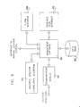
Fig. 2A , which is a simplified block diagram illustration of the system ofFig. 1 in accordance with one preferred embodiment of the present invention. In the embodiment ofFig. 2A , each detector module 106 (Fig. 1 ) comprises a foreignobject sensor module 120, comprising one or more sensors, such as cameras, and related devices as described hereinbelow with reference toFigs. 6A-6C , and alocal processing module 122 which receives at least one output from thesensor module 120 and provides at least an initial determination of whether a foreign object is present.Local processing module 122 preferably comprises a high speed detection output analyzer as described hereinbelow with reference toFigs. 9A-9H and9K-9L , and also preferably includes a multiple sensor correlation algorithm as described hereinbelow with reference toFig. 9I . Eachdetector module 106 communicates, in a wired or wireless manner as most appropriate, via acommunications network 124, such as a LAN, with the computer system 108 (Fig. 1 ). - Reference is now made to
Fig. 2B , which is a simplified block diagram illustration of the system ofFig. 1 in accordance with another preferred embodiment of the present invention. In the embodiment ofFig. 2B , each detector module 106 (Fig. 1 ) comprises a foreign object sensor module 130, comprising one or more sensors, such as cameras, and related devices as described hereinbelow with reference toFigs. 6A-6C . Eachdetector module 106 communicates, in a wired or wireless manner as most appropriate, via acommunications network 132, such as a LAN, with the computer system 108 (Fig. 1 ), which includes acentral processing module 134, which provides at least an initial determination of whether a foreign object is present.Central processing module 134 preferably comprises a high speed detection output analyzer as described hereinbelow with reference toFigs. 9A-9H andFigs. 9K-9L , which preferably also includes a multiple sensor correlation algorithm as described hereinbelow with reference toFig. 9I and a multiple detector correlation algorithm as described hereinbelow with reference toFig. 9J . - Reference is now made to
Fig. 3 , which is a simplified block diagram illustration of a combined system of the type shown inFig. 1 , which incorporates elements of at least one of the types shown inFigs. 2A and2B . As seen inFig. 3 , multiple groups of detector modules 106 (Fig. 1 ) may communicate via multiple computer networks, through management software described hereinbelow with reference toFig. 5 , with acomputer system 140, such ascomputer system 108 ofFig. 1 . For example, first andsecond groups Fig. 1 ), of the type shown inFig. 2A , may communicate viarespective LANs fourth groups Fig. 1 ), of the type shown inFig. 2B , may communicate viarespective LANs computer system 140. - Reference is now made to
Fig. 4A , which is a simplified block diagram illustration of a detector module forming part of the system ofFig. 2A . As seen inFig. 4A , an output signal fromcamera 214 is preferably received by aframe grabber 230 which outputs to digitalsignal processing circuitry 232, which performs image analysis on the output ofcamera 214. Digitalsignal processing circuitry 232 preferably comprises a high speed detection output analyzer as described hereinbelow with reference toFigs. 9A-9H and9K-9L , which also preferably includes a multiple sensor correlation algorithm as described hereinbelow with reference toFig. 9I . - A
controller computer 234 receives an output from digitalsignal processing circuitry 232 and may also receive an output from one or more environmental sensors such assensors Fig. 6A ).Controller computer 234 also provides control outputs toilluminators 212,cameras 214,laser pointers 216 and other elements described hereinabove with reference toFig. 4A . - A
communications module 236 interfaces withcontroller computer 234 and provides data communications via communications network 124 (Fig. 2A ), such as a LAN, with computer system 108 (Fig. 1 ). It is appreciated that the communications may be wired and/or wireless and may employ the existingwiring connection 304 to lamp 308 (Fig. 6A ). - Reference is now made to
Fig. 4B , which is a simplified block diagram illustration of a central processing module forming part of the system ofFig. 2B . As seen inFig. 4B , the central processing module preferably comprises aserver 240 which receives via communications network 132 (Fig. 2B ), such as a LAN, output signals from a plurality of foreign object detector modules 106 (Fig. 2B ) which include sensor modules 130 (Fig. 2B ) and preferably provides them to acentral processing module 242, which preferably comprises parallel processors with the capacity to process all of the output signals in real time.Central processing module 242 preferably comprises a high speed detection output analyzer as described hereinbelow with reference toFigs. 9A-9H and9K-9L , which preferably also includes a multiple sensor correlation algorithm as described hereinbelow with reference toFig. 9I and a multiple detector correlation algorithm as described hereinbelow with reference toFig. 9J .Central processing module 242 preferably communicates, through management software described hereinbelow with reference toFig. 5 , with operator console 107 (Fig. 1 ) to provide an indication of whether a foreign object is present. - Reference is now made to
Fig. 5 , which is a simplified block diagram illustration of a controlling software module forming part of the computer system in accordance with the embodiment ofFig. 2A . The controlling software module is preferably installed in computer system 108 (Fig. 1 ) and comprises acommunication module 250 which handles the communications with the plurality of detector modules 106 (Fig. 2A ) via communications network 124 (Fig. 2A ).Communication module 250 interfaces withmanagement software 252 which, in turn, interfaces with adatabase 254, with agraphical user interface 256 having image manipulation capability provided by software, such as ADOBE® PHOTOSHOP®, and with analarm indicator 258. Additionally,communication module 250 ormanagement software 252 may interface with existing airport control systems. Themanagement software 252 may also interface with a multipledetector correlation algorithm 260, a preferred embodiment of which is described in reference toFig. 9J hereinbelow, which correlates outputs received from multiple detector modules 106 (Fig. 2A ). - It is appreciated that a controlling software module similar to the controlling software module of
Fig. 5 may form part of the embodiment described in reference toFigs. 2B and4B . In such a case, themanagement software 252 communicates via thecommunication module 250 with thecentral processing module 242 ofFig. 4B and does not interface with multipledetector correlation algorithm 260, since this functionality is incorporated intocentral processing module 242. - Reference is now made to
Figs. 6A ,6B and6C , which are simplified pictorial illustrations of three alternative sensor or sensor/processor modules mounted on existing lighting supports useful in the invention ofFigs. 1 - 5 . - Specific reference is now made to
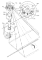
Fig. 6A , which is a simplified pictorial illustration of a preferred embodiment of a detector module forming part of the system ofFig. 2A . As seen inFig. 6A , an existingairport lighting assembly 300, including a base 302 having an undergroundelectrical wiring connection 304, asupport shaft 306 and alamp 308 may provide a platform for thedetector module 309. Preferably asupport surface 310 is mounted ontoshaft 306 belowlamp 308. Mounted ontosupport surface 310 there are preferably provided a plurality ofstatic imaging assemblies 311, each preferably comprising anilluminator 312 and acamera 314.Camera 314 is preferably equipped withoptics 315 including, inter alia, a near IR filter which is employed during daylight operation whenilluminator 312 is not employed. - One or more of the
static imaging assemblies 311 may also comprise a selectablydirectable laser pointer 316 for indicating the location of a suspected foreign object. Alternatively, one or more scanning imaging assemblies may be employed instead of static imaging assemblies. - One or more environmental sensors, such as a
light level sensor 318, avibration sensor 319 and atemperature sensor 320, may also be mounted onsupport surface 310. - Preferably illuminators 312,
cameras 314 and environmental sensors, such assensors communication module 322 which provides electrical power for operation and preferably also provides two-way data communication for controlling the operation of theilluminators 312,cameras 314,optics 315 andlaser pointers 316 as well as processing image data fromcameras 314, including performing initial image analysis thereon and providing foreign object detection output signals and environmental sensor signals via communications network 124 (Fig. 2A ), such as a LAN, to computer system 108 (Fig. 1 ). - Preferably, electrical power supplied to
lamp 308 viawiring 304 is employed to power the detector module and the various elements described hereinabove. Preferably arechargeable battery 323 is provided to store electrical power during times thatlamp 308 is illuminated and to enable such stored electrical power to be used during all other times for powering the detector module and the various elements described hereinabove. - Preferably, the
static imaging assemblies 311 are enclosed within a suitable environmental enclosure 324 which includes portions that are transparent to light as required by theilluminators 312,cameras 314 andlaser pointers 316. - It is appreciated that the detector module of
Fig. 6A may also be useful in the embodiment ofFig. 2B . In such a case, the local processor andcommunication module 322 does not provide local image processing. - It is appreciated that any suitable number of
cameras 314,illuminators 312 andlaser pointers 316 may be included in a detector module. It is also appreciated that the base 302 having undergroundelectrical wiring connection 304, may be replaced by an above-ground support and wiring connection. - Specific reference is now made to
Fig. 6B , which is a simplified pictorial illustration of a preferred embodiment of a detector module forming part of the system ofFig. 2A . As seen inFig. 6B , an existingairport lighting assembly 350, including a base 352 having an undergroundelectrical wiring connection 354, asupport shaft 356 and alamp 358 may provide a platform for the detector module. Preferably asupport bracket 360 is mounted ontoshaft 356 belowlamp 358. Mounted ontosupport bracket 360 there is preferably provided anenclosure 361, which may be similar to enclosure 324 ofFig. 6A , and preferably encloses a plurality ofstatic imaging assemblies 362, each preferably comprising at least oneilluminator 363 and a pair ofcameras cameras Figs. 7B and8B and described hereinbelow in reference thereto. Alternatively,cameras Cameras illuminator 363 is not employed. - Disposed within
enclosure 361 there is preferably provided a selectablydirectable laser pointer 366 for indicating the location of a suspect foreign object. Alternatively, one or more scanning imaging assemblies may be employed instead of static imaging assemblies. - One or more environmental sensors, such as a
light level sensor 368, avibration sensor 369 and atemperature sensor 370, may also be mounted onsupport bracket 360. - Preferably illuminators 363,
cameras 364 & 365 and environmental sensors, such assensors communication module 372 which provides electrical power for operation and preferably also provides two-way data communication for controlling the operation of theilluminators 363,cameras 364 & 365 andlaser pointers 366 as well as processing image data fromcameras 364 & 365, including performing initial image analysis thereon and providing foreign object detection output signals and environmental sensor signals via communications network 124 (Fig. 2A ), such as a LAN, to computer system 108 (Fig. 1 ). - Preferably, electrical power supplied to
lamp 358 viawiring 354 is employed to power the detector module and the various elements described hereinabove. Preferably, arechargeable battery 373 is provided to store electrical power during times thatlamp 358 is illuminated and to enable such stored electrical power to be used during all other times for powering the detector module and the various elements described hereinabove. - It is appreciated that the detector module of
Fig. 6B may also be useful in the embodiment ofFig. 2B . In such a case, the local processor andcommunication module 372 does not provide local image processing. - It is appreciated that any suitable number of
cameras 364 & 365,illuminators 362 andlaser pointers 366 may be included in a detector module. It is also appreciated that the base 352 having undergroundelectrical wiring connection 354, may be replaced by an above-ground support and wiring connection. - Specific reference is now made to
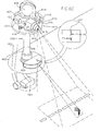
Fig. 6C , which is a simplified pictorial illustration of a preferred embodiment of a detector module forming part of the system ofFig. 2A . As seen inFig. 6C , an existingairport lighting assembly 400, including a base 402 having an undergroundelectrical wiring connection 404, asupport shaft 406 and alamp 408 may provide a platform for the detector module. Preferably asupport surface 410 is mounted ontoshaft 406 belowlamp 408. Mounted ontosupport surface 410 there are preferably provided one or morescanning imaging assemblies 411, each preferably comprising anilluminator 412 and ascanning camera 414.Camera 414 is preferably equipped withoptics 415 including, inter alia, a near IR filter which is employed during daylight operation whenilluminator 412 is not employed. - Mounted onto
support surface 410 there is preferably provided one or more selectablydirectable laser pointers 416 for indicating the location of a suspect foreign object. Alternatively, thelaser pointer 416 may be included in one or more of thescanning imaging assemblies 411. - One or more environmental sensors, such as a
light level sensor 418, avibration sensor 419 and atemperature sensor 420, may also be mounted onsupport surface 410. - In accordance with a preferred embodiment of the present invention, a
scanning illuminator 422 is mounted adjacent the base 402 to direct illumination parallel to and just above an aircraft travel surface, typically up to 2 - 3 cm above the surface. This illumination is designed to illuminate foreign objects on the aircraft travel surface without generally illuminating the travel surface itself, thus greatly increasing contrast. - Preferably illuminators 412 & 422,
cameras 414 and environmental sensors, such assensors communication module 423 which provides electrical power for operation and preferably also provides two-way data communication for controlling the operation of theilluminators 412 & 422,cameras 414 andlaser pointers 416 as well as processing image data fromcameras 414, including performing initial image analysis thereon and providing foreign object detection output signals and environmental sensor signals via communications network 124 (Fig. 2A ), such as a LAN, to computer system 108 (Fig. 1 ). - Preferably, electrical power supplied to
lamp 408 viawiring 404 is employed to power the detector module and the various elements described hereinabove. Preferably, arechargeable battery 424 is provided to store electrical power during times thatlamp 408 is illuminated and to enable such stored electrical power to be used during all other times for powering the detector module and the various elements described hereinabove. - Preferably, the
scanning imaging assemblies 411 are enclosed within a suitableenvironmental enclosure 425 and thescanning illuminator 422 is enclosed within a suitableenvironmental enclosure 426.Enclosures illuminators 412 & 422,cameras 414 andlaser pointers 416. - Preferably at least one
scanning imaging assembly 411 is provided with zoom capabilities for enhancing resolution. - It is appreciated that the detector module of
Fig. 6C may also be useful in the embodiment ofFig. 2B . In such a case, the local processor andcommunication module 423 does not provide local image processing. - It is appreciated that any suitable number of
cameras 414,illuminators 412 & 422 andlaser pointers 416 may be included in a detector module. It is also appreciated that the base 402 having undergroundelectrical wiring connection 404, may be replaced by an above-ground support and wiring connection. - Reference is now made to
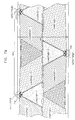
Figs. 7A ,7B and7C , which are simplified illustrations of the azimuthal extent of protected areas provided by an array of sensors of the types shown respectively inFigs. 6A ,6B and6C .Figs. 7A - 7C illustrate an example of use of the invention on a runway having a width of 60 meters, where detector modules are deployed on both sides of the runway every 100 meters inFigs. 7A and7C , and every 200 meters inFig. 7B . It is assumed that the runway surface is inclined downwardly towards its side edges for drainage purposes. - Turning to
Fig. 7A , it is seen that eachdetector module 309 ofFig. 6A , designated here byreference numeral 450 and having three static imaging assemblies 311 (Fig. 6A ) typically at an elevation of 50 cm above the runway, provides slightly less than 180 degree overall coverage of one side of the runway, eachimaging assembly 311 providing 60 degree coverage which slightly overlaps with that provided by anadjacent imaging assembly 311. In the illustrated example, each ofdetectors detector 1 are designated as camera #1 - 1, camera #1 - 2 and camera #1 - 3. Similar designations are used for the cameras ofdetectors - Turning to
Fig. 7B , it is seen that each detector module ofFig. 6B , designated here byreference numeral 452 and having two static imaging assemblies 362 (Fig. 6B ), each including first and second mutually stackedcameras 364 & 365, typically at elevations of approximately 80 cm above the runway, provides slightly less than 180 degree overall coverage of one side of the runway, eachimaging assembly 362 providing 90 degree coverage which slightly overlaps with that provided by anadjacent imaging assembly 362. Here, it is seen thatlower cameras 365 have fields of view which are located relatively close to the edge of the runway, whilehigher cameras 364 have fields of view which slightly overlap the fields of view ofcameras 365 and extend beyond the center of the runway. It is appreciated that even though the illustrated embodiment showscameras - In the illustrated example, each of
detectors detector 1 are designated as camera #1 - 1, camera #1 - 2, camera #1 - 3 and camera #1 - 4. Similar designations are used for the cameras ofdetectors - Turning to
Fig. 7C , it is seen that each detector module ofFig. 6C , designated here byreference numeral 454 and having at least one scanning imaging assembly 411 (Fig. 6C ) typically at an elevation of 50 cm above the runway, provides 180 degree overall coverage of one side of the runway. - Reference is now made to
Figs. 8A, 8B and 8C , which are simplified illustrations of the elevational extent of protected areas provided by an array of sensors of the types shown respectively inFigs. 6A ,6B and6C . It is appreciated thatFigs. 8A - 8C are not drawn to scale in order to emphasize the effect of the incline of the runway from its center to its sides, which is practice is about 2%. -
Fig. 8A illustrates that in the illustrated example, the field of view of imaging assembly 311 (Fig. 6A ) extends generally to the center of the runway.Fig. 8B illustrates that in the illustrated example, the field of view of imaging assembly 362 (Fig. 6B ) partly extends beyond the center of the runway.Fig. 8B also shows that lower cameras 365 (Fig. 6B ) have fields of view which are located relatively close to the edge of the runway, while higher cameras 364 (Fig. 6B ) have fields of view which slightly overlap the fields of view of cameras 365 (Fig. 6B ) and extend beyond the center of the runway.Fig. 8C illustrates that in the illustrated example, the field of view of imaging assembly 411 (Fig. 6C ) extends generally to the center of the runway.Fig. 8C also shows the effect of a zoom in function providing a narrower, higher resolution, field ofview 460 than the zoom out function, which scans fields ofview - Reference is now made to
Figs. 9A - 9L , which, together, are a simplified flowchart illustrating the operation of a high speed detection output analyzer forming a portion of a system for detection of foreign objects on airport travel surfaces in accordance with a preferred embodiment of the present invention. - Turning to
Fig. 9A , it is seen that operation of the high speed detection output analyzer forming a portion of the system for detection of foreign objects on airport travel surfaces in accordance with a preferred embodiment of the present invention may begin with receipt of a light level indication, such as fromlight level sensor 318 in the embodiment ofFig. 6A ,light level sensor 368 in the embodiment ofFig. 6B orlight level sensor 418 in the embodiment ofFig. 6C . Based on the light level, day (normal visibility) or night (impaired visibility) operation is indicated. - During daytime, assuming that weather conditions do not impair visibility, each detector module, such as detector modules 106 (
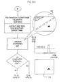
Figs. 1 ,2A &2B ) and the detector modules described hereinabove in connection withFigs. 6A - 6C , captures at least one frame in its field of view. A typical frame, being part of a runway, is designated byreference numeral 502. If the frame capture is an initial day or night frame capture for a detector module, the analyzer processesframe 502 according to the single frame detection algorithm described hereinbelow in reference toFigs. 9B - 9F . If the frame capture is not an initial day or night frame capture for a detector module, the analyzer processesframe 502 according to the change detection algorithm described hereinbelow in reference toFigs. 9G - 9H and not falling whithin the scope of this invention - Turning to
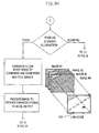
Fig. 9B , extraction of an airport travel surface, preferably by frame segmentation, takes place, yielding an image showing only the aircraft travel surface, here designated byreference numeral 504 inFig. 9B . - A histogram or other suitable representation of the distribution of grey-level pixels on the aircraft travel surface is then preferably generated in order to determine a typical airport travel surface pixel grey level. An example of such a histogram is here designated by
reference numeral 506. - Suspect areas on the aircraft travel surface are then located by finding non-typical airport travel surface pixels. This is preferably accomplished, as shown in
Fig. 9C , by generating local histograms by employing a running window as illustrated atreference numeral 508. Each local histogram is compared with an expected value and a map of suspect areas is generated based on differences between local histogram values and expected histogram values. An example of such a map is designated byreference numeral 510. - Preferably, while the steps illustrated in
Figs. 9B and9C take place, a parallel analysis also occurs, as shown inFig. 9D . Turning toFig. 9D , it is seen that edge detection is carried out on frame 502 (Fig. 9A ) in order to find unexpected edges which may indicate the presence of foreign objects. Examples of detected edges are indicated byreference numerals reference numerals enclosed areas 516, which together match expectededge configuration 517. It is noted that theedge 518, which corresponds to a foreign object, does not have a matching configuration in the database. - A map, here designated by
reference numeral 519, is generated to indicate the location of the non-matched, suspect detected edge and the extent to which the suspect detected edge differs from the matching configuration in the database. - Turning to
Fig. 9E , it is seen that the results of the parallel processes described above inFigs. 9B - 9C and9D respectively are correlated in order to determine whether a foreign object is deemed to have been located. This is preferably carried out by comparing a histogram map here designated byreference numeral 520 with an edge map, here designated byreference numeral 522. - If a foreign object is deemed to have been located, a message is sent to a human operator through any suitable medium or media and a "marked up" version of frame 502 (
Fig. 9A ), here designated byreference numeral 524, emphasizing the location of the foreign object and providing location information, is displayed for the operator. - As indicated in
Fig. 9F , upon receipt of an acknowledgment from the human operator of his receipt of the message, a foreign object designator, such as a laser pointer 110 (Fig. 1 ) may be directed at the foreign object, as illustrated atreference numeral 526. - If a foreign object is not found by correlation or should the operator determine that a foreign object is not present, the frame 502 (
Fig. 9A ) and the data generated relative thereto as described hereinabove, together with a global histogram of frame 502 (Fig. 9A ), here indicated byreference numeral 528, are stored in a database, which may or may not be local to a given detector module. The stored information may be used as a base image for later comparison. It may be used together with multiple stored based images, which are preferably historically deweighted. - Turning to
Figs. 9G and9H , if the frame capture is not an initial frame capture for a detector module, a global histogram is generated for the current frame, as designated byreference numeral 530 and this global histogram is compared with one or more stored global histograms of preceding frames, preferably employing histogram equalization, as illustrated atreference numeral 532. - In addition, the current frame and the base frame images are brought into registration and compared, as illustrated at
reference numeral 534, to indicate changes therebetween and a difference map, designated byreference numeral 536, is produced. The difference map is thresholded, to render a thresholded difference map, as indicated byreference numeral 538. If peaks remain in the thresholded difference map a multi-sensor analysis is conducted, as indicated inFig. 9I . - In the illustrated embodiment, the multi-sensor analysis is carried out in two stages, initially employing outputs of sensors, such as cameras, on a single detector module and thereafter on outputs of sensors, such as cameras, on multiple detector modules. Alternatively, any other suitable multi-sensor analysis regime may be employed.
- As seen in
Figs. 9I and9J , suspected foreign object information is received from multiple sensors, such ascameras 314, indetector module 309, in the embodiment ofFig. 6A . This information preferably includes size, shape and associated gray levels of the suspected foreign object detected, and location information within the field of view of the sensor. Additionally, theglobal histogram map 530 ofFig. 9G and thedifference map 536 ofFig. 9H may also be included in the information received. This information from multiple sensors is considered together and compared with stored information which helps to distinguish detected patterns extending over the fields ofview 540 of multiple sensors, such asskid marks 542, which do not constitute foreign objects, from an actualforeign object 544. - If a foreign object is still believed to be present, suspected foreign object information is received from multiple sensors, such as cameras, in multiple detector modules. This information preferably includes size, shape and associated gray levels of the suspected foreign object detected, and location information within the field of view of the detector. Additionally, the
global histogram map 530 ofFig. 9G and thedifference map 536 ofFig. 9H may also be included in the information received. This information from multiple detectors is considered together and compared with stored information which helps to distinguish detected patterns extending over the fields ofview 550 of multiple sensors, such as cameras, onmultiple detector modules 552, such asslush 554 or a moving vehicle, which do not constitute foreign objects, from an actualforeign object 556. - Reference is now made to
Fig. 9K , which illustrates operation in an impaired visibility environment. If fixed illumination is employed, multiple images are captured at multiple times and combined, for example by averaging, to provide a combined noise reducedframe 560 for analysis. - As seen in
Fig. 9L , if scanning illumination is employed, the operation of the scanner and of the camera is synchronized to provide asuitable frame 562 for analysis. - The
frames frame 502, captured during the day. It is appreciated that frames captured under impaired visibility conditions may be analyzed entirely or partially separately from frames captured under full visibility conditions. - It will be appreciated by persons skilled in the art that the present invention is not limited by what has been particularly shown and described hereinabove. Rather the scope of the present invention is to be determined with reference to the claims.
Claims (17)
- A system for detection of foreign objects on an airport travel surface comprising:a plurality of foreign object detector modules (106) mounted on a corresponding plurality of existing aircraft travel surface lighting supports, each foreign object detector module (106) being configured to capture at least one image (502) in its field of view and provide a corresponding detection-output; the at least one image captured by each foreign object detector module including a part of the airport travel surface; and a detection output analyzer operative to receive said detection output and to provide an output indication of foreign object presence;
characterized in that the output analyzer is configured in a single frame capture algorithm:to extract said airport travel surface, vielding an image showing only the aircraft travel surface (504),to determine a typical airport travel surface pixel grey level from a representation (506) of the distribution of the grey-level pixels in the image, andto locate suspect areas on the aircraft travel surface by finding pixels (510) with a non-typical airport travel surface grey level by comparison with the typical airport travel surface pixel grey level. - A system for detection of foreign objects on airport travel surfaces according to claim 1 wherein said airport travel surfaces include at least one taxiway and at least one runway (102) and said system employs at least some existing electrical power infrastructure associated with existing runway (102) and taxiway lighting fixtures (104).
- A system for detection of foreign objects on airport travel surfaces according to any of the preceding claims and wherein:said plurality of foreign object detector modules (106) communicate with a computer system (108) comprising an operator console (107) operative to provide a foreign object presence alarm and an image of the foreign object to an operator; andsaid detection output analyzer is located in the vicinity of said operator console (107).
- A system for detection of foreign objects on airport travel surfaces according to any of the preceding claims and also including a selectably directable laser pointer (110) associated with at least one of said plurality of foreign object detector modules (106) to assist in on-site inspections.
- A system for detection of foreign objects on airport travel surfaces according to any of the preceding claims and wherein at least one of said plurality of foreign object detector modules (106) incorporates at least one foreign object sensor module and a local processing module (122) which receives an output from said at least one foreign object sensor modules and provides said detection output including at least an initial determination of whether a foreign object is present.
- A system for detection of foreign objects according to claim 5 and wherein said local processing module (122) comprises a multiple sensor algorithm providing an output based on said output from multiple ones of said at least one foreign object sensor module in said detector module (106).
- A system for detection of foreign objects on airport travel surfaces according to any of the preceding claims and wherein at least one of said plurality of foreign object detector modules (106) incorporates at least one foreign object sensor module which provides said detection output to said detection output analyzer which is remotely located with respect thereto.
- A system for detection of foreign objects according to claim 7 and wherein said detection output analyzer comprises at least one of multiple sensor correlation software and multiple detector correlation software, said multiple sensor correlation software providing an output based on the correlation between said detection output from multiple ones of said at least one foreign object sensor module in individual ones of said plurality of detector modules (106) and said multiple detector correlation software providing an output based on the correlation between said detection output from multiple ones of said at least one foreign object sensor module in multiple ones of said plurality of detector modules (106).
- A system for detection of foreign objects on airport travel surfaces according to any of the preceding claims wherein:each of said plurality of foreign object detector modules (106) comprises a foreign object sensor module comprising at least one camera (314) and at least one illuminator (312);said at least one camera (314) includes at least one of a fixed field camera, a scanning camera and a scanning camera including a zoom functionality; andsaid at least one illuminator (312) includes at least one of a fixed field illuminator (312) and a scanning illuminator (312).
- A system for detection of foreign objects on airport travel surfaces according to any of the preceding claims wherein each of said plurality of foreign object detector modules (106) also has associated therewith at least one of a light level sensor, a vibration sensor and a temperature sensor.
- A system for detection of foreign objects on airport travel surfaces according to any of the preceding claims and also comprising controlling software which comprises:a communication module (250) which handles communications with said plurality of detector modules (106) via a communications network (124); andmanagement software which interfaces with said communications module, with existing airport control systems, and with a database, a graphical user interface having image manipulation capability and an alarm indicator (258).
- A system according to claim 11 and wherein said management software also interfaces with multiple sensor correlation software, which provides information based on outputs from multiple ones of said plurality of detector modules (106).
- A system for detection of foreign objects according to any of the preceding claims and wherein said detector output analyzer provides at least first and second modes of operation, said first mode of operation being employed under conditions of normal visibility and said second mode of operation being employed under conditions of impaired visibility.
- A system for detection of foreign objects on airport travel surfaces according to any of the preceding claims and also comprising a storage unit, for storing said detection outputs in a time sequence and wherein said detection output analyzer is operative to compare said detection outputs to said stored detection outputs.
- A system for detection of foreign objects on airport travel surfaces according to any of the preceding claims and wherein said plurality of foreign object detector modules (106) include at least one of foreign object detector modules (106) having at least partially overlapping fields of view and foreign object detector modules (106) including a plurality of cameras, wherein said cameras have at least partially overlapping fields of view.
- A method for detection of foreign objects on an airport travel surface, comprising the steps:mounting a plurality of foreign object detector modules (106) on a corresponding plurality of existing aircraft travel surface lighting supports:operating said plurality of foreign object detector modules (106), each foreign object detector module (106) being configured to capture at least one image (502) in its field of view and to provide a corresponding detection output, the at least one image captured by each foreign object detector module including a part of the airport travel surface; andanalyzing said detection output to provide an output indication of foreign object presence:
characterized by comprising the further steps in a single frame capture algorithm:extracting said airport travel surface, yielding an image showing only the airport travel surface (504):determining a typical airport travel surface pixel grey level from a representation (506) of the distribution of the grey-level pixels in the image; andlocating suspect areas on the aircraft travel surface by finding pixels (510) with a non-typical airport travel surface grey level by comparison with the typical travel surface pixel grey level. - A method for detection of foreign objects on airport travel surfaces according to claim 17 and also including operating a selectably directable laser pointer (110) associated with at least one of said plurality of foreign object detector modules (106) to assist in on-site inspections.
Priority Applications (1)
| Application Number | Priority Date | Filing Date | Title |
|---|---|---|---|
| EP08014340A EP1995707B1 (en) | 2002-10-28 | 2003-10-23 | Foreign object detection system |
Applications Claiming Priority (3)
| Application Number | Priority Date | Filing Date | Title |
|---|---|---|---|
| US281772 | 1994-07-28 | ||
| US10/281,772 US6917309B2 (en) | 2002-10-28 | 2002-10-28 | Foreign object detection system and method |
| PCT/IL2003/000869 WO2004038675A2 (en) | 2002-10-28 | 2003-10-23 | Foreign object detection system and method |
Related Child Applications (1)
| Application Number | Title | Priority Date | Filing Date |
|---|---|---|---|
| EP08014340A Division EP1995707B1 (en) | 2002-10-28 | 2003-10-23 | Foreign object detection system |
Publications (3)
| Publication Number | Publication Date |
|---|---|
| EP1561190A2 EP1561190A2 (en) | 2005-08-10 |
| EP1561190A4 EP1561190A4 (en) | 2006-07-26 |
| EP1561190B1 true EP1561190B1 (en) | 2008-08-13 |
Family
ID=32107231
Family Applications (2)
| Application Number | Title | Priority Date | Filing Date |
|---|---|---|---|
| EP08014340A Expired - Lifetime EP1995707B1 (en) | 2002-10-28 | 2003-10-23 | Foreign object detection system |
| EP03758631A Expired - Lifetime EP1561190B1 (en) | 2002-10-28 | 2003-10-23 | Foreign object detection system and method |
Family Applications Before (1)
| Application Number | Title | Priority Date | Filing Date |
|---|---|---|---|
| EP08014340A Expired - Lifetime EP1995707B1 (en) | 2002-10-28 | 2003-10-23 | Foreign object detection system |
Country Status (7)
| Country | Link |
|---|---|
| US (4) | US6917309B2 (en) |
| EP (2) | EP1995707B1 (en) |
| AT (2) | ATE404964T1 (en) |
| AU (1) | AU2003274659A1 (en) |
| CA (1) | CA2505841C (en) |
| DE (2) | DE60322936D1 (en) |
| WO (1) | WO2004038675A2 (en) |
Families Citing this family (31)
| Publication number | Priority date | Publication date | Assignee | Title |
|---|---|---|---|---|
| US6917309B2 (en) * | 2002-10-28 | 2005-07-12 | Integritech System Engineering Ltd. | Foreign object detection system and method |
| EP1460605A1 (en) * | 2003-03-20 | 2004-09-22 | Siemens Aktiengesellschaft | Airportlighting unit and system |
| US7450004B2 (en) * | 2004-10-29 | 2008-11-11 | The Boeing Company | Systems and methods for handling information from wireless nodes, including nodes for communication with aircraft |
| CA2656995C (en) * | 2006-07-19 | 2012-07-10 | Cubic Corporation | Use of zigbee personal area network in miles manworn |
| US7796055B2 (en) * | 2006-11-02 | 2010-09-14 | The Boeing Company | Runway status indication and traffic information display and filtering |
| FR2910161B1 (en) * | 2006-12-15 | 2009-01-30 | Thales Sa | GONIOMETRIC SYSTEM OF MINI SENSORS DOPPLER IN NETWORKS FOR THE MONITORING OF PERIMETERS |
| US20100283608A1 (en) * | 2007-01-04 | 2010-11-11 | Honeywell International Inc. | Intrusion Warning and Reporting Network |
| TW200838767A (en) * | 2007-03-23 | 2008-10-01 | kun-yuan Zhang | Airport runway warning system |
| BRPI0817039A2 (en) * | 2007-08-24 | 2015-07-21 | Stratech Systems Ltd | Runway surveillance system and method |
| US7782251B2 (en) * | 2007-10-06 | 2010-08-24 | Trex Enterprises Corp. | Mobile millimeter wave imaging radar system |
| US20110001635A1 (en) * | 2007-11-09 | 2011-01-06 | Motorola, Inc. | Mobile traffic monitoring system |
| US8022841B2 (en) * | 2008-03-31 | 2011-09-20 | Xsight Systems Ltd. | System and method for ascription of foreign object debris detected on airport travel surfaces to foreign object sources |
| US8255156B2 (en) * | 2008-05-19 | 2012-08-28 | The Boeing Company | Spatial source collection and services system |
| US7767966B2 (en) * | 2008-06-20 | 2010-08-03 | Bowling Green State University | Method and apparatus for detecting organic materials and objects from multispectral reflected light |
| US8030615B2 (en) * | 2008-06-20 | 2011-10-04 | Bowling Green State University | Method and apparatus for detecting organic materials and objects from multispectral reflected light |
| US20100023191A1 (en) * | 2008-07-22 | 2010-01-28 | Arinc Incorporated | Method and apparatus for wireless runway incursion detection |
| US9135830B2 (en) | 2010-02-18 | 2015-09-15 | Xsight Systems Ltd. | Airport travel surface edge lighting and foreign object detection system and method |
| RU2596246C2 (en) * | 2011-02-21 | 2016-09-10 | Стратек Системс Лимитед | Observation system and method of detecting contamination or damage of aerodrome with foreign objects |
| US8717169B2 (en) * | 2011-06-06 | 2014-05-06 | Velocity Metrics, Llc | Air traffic controller alerting system |
| US11037319B2 (en) * | 2013-04-15 | 2021-06-15 | X - Sight Systems Ltd. | Contaminant detection and bird risk management at airports |
| CN103412345B (en) * | 2013-08-16 | 2016-01-06 | 中国舰船研究设计中心 | Automatic aircraft carrier flight deck foreign matter detection recognition system |
| JP6293552B2 (en) * | 2014-03-31 | 2018-03-14 | 株式会社日立製作所 | Monitoring management system |
| GB2527536A (en) * | 2014-06-25 | 2015-12-30 | Bae Systems Plc | Glide path indicator |
| US10984662B2 (en) * | 2016-11-24 | 2021-04-20 | X—Sight Systems Ltd. | Runway activity monitoring, logging and analysis for aircraft touchdown detection and abnormal behavior alerting |
| EP3151164A3 (en) * | 2016-12-26 | 2017-04-12 | Argosai Teknoloji Anonim Sirketi | A method for foreign object debris detection |
| JP6954749B2 (en) * | 2017-03-03 | 2021-10-27 | 株式会社Soken | Adhesion detection device |
| KR101910887B1 (en) | 2017-03-06 | 2018-10-23 | 주식회사유넷컨버전스 | Method of displaying the location of the foreign substance within the runway |
| CN107247262B (en) * | 2017-05-31 | 2019-11-19 | 中国电子科技集团公司第二十九研究所 | A kind of airfield runway foreign matter layer detection method |
| DE102018222597A1 (en) | 2018-12-20 | 2020-06-25 | Thyssenkrupp Ag | Method for recognizing an obstacle at an aircraft position |
| CN111524324B (en) * | 2020-03-20 | 2022-07-29 | 北京首都国际机场股份有限公司 | FOD alarm level determination method, electronic device and storage medium |
| CN112904452A (en) * | 2021-01-25 | 2021-06-04 | 中国民用航空总局第二研究所 | Built-in anti-drop structure of sidelight formula FOD detection equipment |
Family Cites Families (43)
| Publication number | Priority date | Publication date | Assignee | Title |
|---|---|---|---|---|
| US3609677A (en) * | 1965-10-22 | 1971-09-28 | Gayle Russell Norberg | Direction indicating beacons |
| FR2202332B1 (en) * | 1972-10-05 | 1979-02-09 | Labo Cent Telecommunicat | |
| US3878506A (en) * | 1973-08-03 | 1975-04-15 | David W Young | Airport lighting and radar reflector combination |
| US4499527A (en) * | 1983-05-27 | 1985-02-12 | Cooper Industries, Inc. | Airport runway/taxiway edge light fixture |
| US4792904A (en) * | 1987-06-17 | 1988-12-20 | Ltv Aerospace And Defense Company | Computerized flight inspection system |
| US4891976A (en) * | 1988-04-07 | 1990-01-09 | Chato John D | Device employing resonant chambers to determine wind characteristics |
| SE462698B (en) * | 1988-10-07 | 1990-08-13 | Swedish Airport Technology Han | FAIR LIGHTING FOR AIRPORT |
| US5003441A (en) * | 1989-06-30 | 1991-03-26 | Crowe John R | Pop-up light fixture |
| KR920003198A (en) * | 1990-07-06 | 1992-02-29 | 카가야세이치 | Moving object detection method by image processing and apparatus therefor and distance measuring device using this apparatus |
| FI87948C (en) * | 1991-03-07 | 1993-03-10 | Idman Oy | BELYSNINGSANORDNING, SPECIELLT ETT ANFLYGNINGSBLINKLJUS FOER EN RULLBANA |
| US5185815A (en) * | 1991-11-04 | 1993-02-09 | Grumman Aerospace Corporation | Multiple target correlator system |
| US5375058A (en) * | 1991-12-20 | 1994-12-20 | University Of Central Florida | Surface detection system for airports |
| CA2114755A1 (en) * | 1993-02-26 | 1994-08-27 | Peter L. Hoover | Airport surveillance system |
| US5574443A (en) * | 1994-06-22 | 1996-11-12 | Hsieh; Chi-Sheng | Vehicle monitoring apparatus with broadly and reliably rearward viewing |
| US5629691A (en) * | 1995-05-26 | 1997-05-13 | Hughes Electronics | Airport surface monitoring and runway incursion warning system |
| US6575597B1 (en) * | 1995-08-23 | 2003-06-10 | Science & Engineering Associates, Inc. | Non-lethal visual bird dispersal system |
| DE19623504C1 (en) * | 1996-06-13 | 1997-07-10 | Deutsche Forsch Luft Raumfahrt | Optical microphone using Fabry-Perot interferometer and fibre=optics feed line |
| US6064429A (en) | 1997-08-18 | 2000-05-16 | Mcdonnell Douglas Corporation | Foreign object video detection and alert system and method |
| US6542086B2 (en) * | 1997-09-22 | 2003-04-01 | Siemens Aktiengesellschaft | Docking system for airport terminals |
| US6126299A (en) * | 1997-10-08 | 2000-10-03 | James S Hypes | Laser light navigational safety system for improved detectability in low visibility conditions |
| AU2449299A (en) * | 1997-12-17 | 1999-07-05 | James C. O'meara | Laser lighting system |
| US5939987A (en) * | 1998-01-26 | 1999-08-17 | Cram; Randall S. | Roadside deer warning method and system |
| US6155703A (en) * | 1998-10-06 | 2000-12-05 | Physical Optics Corporation | Surface mounted light assembly |
| US6246320B1 (en) * | 1999-02-25 | 2001-06-12 | David A. Monroe | Ground link with on-board security surveillance system for aircraft and other commercial vehicles |
| US6181261B1 (en) * | 1999-06-24 | 2001-01-30 | The United States Of America As Represented By The Secretary Of The Army | Airfield hazard automated detection system |
| NL1013556C2 (en) * | 1999-07-26 | 2001-01-29 | Robertus Gerardus De Boer | Device for determining the position of vehicles at an airport. |
| US6509844B1 (en) * | 1999-08-16 | 2003-01-21 | Chris Eyring | Apparatus and method for providing a portable landing zone |
| US6380871B1 (en) * | 1999-11-30 | 2002-04-30 | Optical Systems, Inc. | System for and method of searching for targets in a marine environment |
| DE10104950A1 (en) * | 2000-03-11 | 2001-10-04 | Apm Gmbh Airport Equipment | Device for directing traffic at airports or on ships uses groups of sensors to identify vehicles or aircraft and/or to monitor a runway status and assess traffic movements. |
| DE10032433A1 (en) * | 2000-07-04 | 2002-01-17 | H A N D Gmbh | Ground space monitoring procedures |
| US6281806B1 (en) * | 2000-10-12 | 2001-08-28 | Ford Global Technologies, Inc. | Driver road hazard warning and illumination system |
| US6606035B2 (en) * | 2000-11-17 | 2003-08-12 | Safe Landing Systems Inc. | System and method for airport runway monitoring |
| US7148815B2 (en) * | 2000-12-22 | 2006-12-12 | Byron Scott Derringer | Apparatus and method for detecting objects located on an airport runway |
| US6563432B1 (en) * | 2001-01-12 | 2003-05-13 | Safegate International Ab | Aircraft docking system and method with automatic checking of apron and detection of fog or snow |
| FR2820867A1 (en) | 2001-02-09 | 2002-08-16 | Philippe Gouvary | AUTOMATED PROCESS FOR MONITORING AND ORGANIZING THE MOVEMENT OF VEHICLES ON THE GROUND AND IDENTIFICATION OF FOREIGN BODIES ON THE TRACKS IN AN AIRPORT ZONE |
| US6486825B1 (en) * | 2001-05-02 | 2002-11-26 | Omaha Airport Authority | Runway incursion detection and warning system |
| CA2348212A1 (en) * | 2001-05-24 | 2002-11-24 | Will Bauer | Automatic pan/tilt pointing device, luminaire follow-spot, and 6dof 3d position/orientation calculation information gathering system |
| US6940424B2 (en) * | 2001-11-13 | 2005-09-06 | Precise Flight, Inc. | Hazard avoidance system |
| US6956493B1 (en) * | 2002-02-15 | 2005-10-18 | Tena Youngblood | Portable sensing light |
| US6917309B2 (en) * | 2002-10-28 | 2005-07-12 | Integritech System Engineering Ltd. | Foreign object detection system and method |
| US7495600B2 (en) * | 2003-12-29 | 2009-02-24 | Itt Manufacturing Enterprise, Inc. | Airfield surface target detection and tracking using distributed multilateration sensors and W-band radar sensors |
| US6972714B1 (en) * | 2004-06-08 | 2005-12-06 | Agilent Technologies, Inc. | Optically-augmented microwave imaging system and method |
| JP4595833B2 (en) * | 2006-02-24 | 2010-12-08 | トヨタ自動車株式会社 | Object detection device |
-
2002
- 2002-10-28 US US10/281,772 patent/US6917309B2/en not_active Expired - Lifetime
-
2003
- 2003-10-23 DE DE60322936T patent/DE60322936D1/en not_active Expired - Lifetime
- 2003-10-23 AT AT03758631T patent/ATE404964T1/en not_active IP Right Cessation
- 2003-10-23 DE DE60336279T patent/DE60336279D1/en not_active Expired - Lifetime
- 2003-10-23 AT AT08014340T patent/ATE500584T1/en not_active IP Right Cessation
- 2003-10-23 WO PCT/IL2003/000869 patent/WO2004038675A2/en active IP Right Grant
- 2003-10-23 CA CA2505841A patent/CA2505841C/en not_active Expired - Fee Related
- 2003-10-23 AU AU2003274659A patent/AU2003274659A1/en not_active Abandoned
- 2003-10-23 EP EP08014340A patent/EP1995707B1/en not_active Expired - Lifetime
- 2003-10-23 EP EP03758631A patent/EP1561190B1/en not_active Expired - Lifetime
-
2005
- 2005-06-06 US US11/145,897 patent/US7253748B2/en not_active Expired - Lifetime
-
2007
- 2007-06-28 US US11/823,835 patent/US7663507B2/en not_active Expired - Lifetime
-
2010
- 2010-01-13 US US12/686,887 patent/US20100109913A1/en not_active Abandoned
Also Published As
| Publication number | Publication date |
|---|---|
| WO2004038675A3 (en) | 2004-12-09 |
| WO2004038675A2 (en) | 2004-05-06 |
| US20100109913A1 (en) | 2010-05-06 |
| EP1995707A3 (en) | 2009-03-25 |
| DE60336279D1 (en) | 2011-04-14 |
| EP1561190A4 (en) | 2006-07-26 |
| EP1995707B1 (en) | 2011-03-02 |
| US6917309B2 (en) | 2005-07-12 |
| US7253748B2 (en) | 2007-08-07 |
| US20040080433A1 (en) | 2004-04-29 |
| US20070296611A1 (en) | 2007-12-27 |
| DE60322936D1 (en) | 2008-09-25 |
| CA2505841C (en) | 2014-10-14 |
| US7663507B2 (en) | 2010-02-16 |
| US20070008185A1 (en) | 2007-01-11 |
| EP1561190A2 (en) | 2005-08-10 |
| CA2505841A1 (en) | 2004-05-06 |
| ATE500584T1 (en) | 2011-03-15 |
| EP1995707A2 (en) | 2008-11-26 |
| AU2003274659A1 (en) | 2004-05-13 |
| ATE404964T1 (en) | 2008-08-15 |
| AU2003274659A8 (en) | 2004-05-13 |
Similar Documents
| Publication | Publication Date | Title |
|---|---|---|
| EP1561190B1 (en) | Foreign object detection system and method | |
| CN102435173B (en) | System and method for quickly inspecting tunnel disease based on machine vision | |
| WO2017039259A1 (en) | Apparatus and method for diagnosing electric power equipment using thermal imaging camera | |
| US6812846B2 (en) | Spill detector based on machine-imaging | |
| CN105389921B (en) | A kind of monitoring system and method for airfield runway foreign matter | |
| CN108332927A (en) | A kind of bridge surface crack detection device | |
| WO2019132131A1 (en) | Multi-wavelength image analysis electro-optical system for detecting accident vessel and victim | |
| KR20170058827A (en) | Security system and security process and security controller of throw trash, by detected humans action or shape image | |
| CN106339657A (en) | Straw incineration monitoring method and device based on monitoring video | |
| JP2004325165A (en) | Foreign substance detection device, method, and mine detection device | |
| WO2006059998A1 (en) | Vehicle-undercarriage inspection system | |
| JP2002162343A (en) | Judgement method of road surface condition by visual picture type road surface condition finding equipment | |
| JP2007164375A (en) | Three-dimensional object detection device and method, computer readable medium and three-dimensional object management system | |
| JPWO2020158262A1 (en) | Deterioration diagnosis device, deterioration diagnosis system, deterioration diagnosis method, program | |
| JP2003162795A (en) | Sensor selecting method using weather data and road traffic monitoring system using the same | |
| JP2004005206A (en) | Road status photographing apparatus, traffic control equipment and traffic control method | |
| JPH03265985A (en) | Plate segmenting device for automatic car number reader | |
| KR20220156140A (en) | River water pollution system monitoring | |
| CN110427911A (en) | A kind of Approach for road detection, device, equipment and storage medium | |
| JP2000193419A (en) | Tire chain detecting device and studless tire detecting device | |
| JP2000023142A (en) | Picture monitoring device | |
| JP2001103496A (en) | Image processor | |
| JP2002298144A (en) | Automatic target detection and identification processing method, device, and program, recording medium and visual camera device | |
| CN113194589B (en) | Airport navigation aid light single lamp fault monitoring method based on video analysis | |
| JP2001126183A (en) | Device for detecting traffic flow |
Legal Events
| Date | Code | Title | Description |
|---|---|---|---|
| PUAI | Public reference made under article 153(3) epc to a published international application that has entered the european phase |
Free format text: ORIGINAL CODE: 0009012 |
|
| 17P | Request for examination filed |
Effective date: 20050524 |
|
| AK | Designated contracting states |
Kind code of ref document: A2 Designated state(s): AT BE BG CH CY CZ DE DK EE ES FI FR GB GR HU IE IT LI LU MC NL PT RO SE SI SK TR |
|
| AX | Request for extension of the european patent |
Extension state: AL LT LV MK |
|
| DAX | Request for extension of the european patent (deleted) | ||
| A4 | Supplementary search report drawn up and despatched |
Effective date: 20060626 |
|
| RIC1 | Information provided on ipc code assigned before grant |
Ipc: G08G 5/06 20060101AFI20060620BHEP Ipc: B64F 1/20 20060101ALN20060620BHEP |
|
| 17Q | First examination report despatched |
Effective date: 20060928 |
|
| RIN1 | Information on inventor provided before grant (corrected) |
Inventor name: NITZAN, ALON Inventor name: GOLAN, AVIRAM Inventor name: GONER, AVIV Inventor name: FISHER, MOSHE |
|
| GRAP | Despatch of communication of intention to grant a patent |
Free format text: ORIGINAL CODE: EPIDOSNIGR1 |
|
| GRAS | Grant fee paid |
Free format text: ORIGINAL CODE: EPIDOSNIGR3 |
|
| GRAA | (expected) grant |
Free format text: ORIGINAL CODE: 0009210 |
|
| AK | Designated contracting states |
Kind code of ref document: B1 Designated state(s): AT BE BG CH CY CZ DE DK EE ES FI FR GB GR HU IE IT LI LU MC NL PT RO SE SI SK TR |
|
| REG | Reference to a national code |
Ref country code: GB Ref legal event code: FG4D |
|
| REG | Reference to a national code |
Ref country code: CH Ref legal event code: EP |
|
| REG | Reference to a national code |
Ref country code: IE Ref legal event code: FG4D |
|
| REF | Corresponds to: |
Ref document number: 60322936 Country of ref document: DE Date of ref document: 20080925 Kind code of ref document: P |
|
| PG25 | Lapsed in a contracting state [announced via postgrant information from national office to epo] |
Ref country code: NL Free format text: LAPSE BECAUSE OF FAILURE TO SUBMIT A TRANSLATION OF THE DESCRIPTION OR TO PAY THE FEE WITHIN THE PRESCRIBED TIME-LIMIT Effective date: 20080813 Ref country code: ES Free format text: LAPSE BECAUSE OF FAILURE TO SUBMIT A TRANSLATION OF THE DESCRIPTION OR TO PAY THE FEE WITHIN THE PRESCRIBED TIME-LIMIT Effective date: 20081124 |
|
| PG25 | Lapsed in a contracting state [announced via postgrant information from national office to epo] |
Ref country code: FI Free format text: LAPSE BECAUSE OF FAILURE TO SUBMIT A TRANSLATION OF THE DESCRIPTION OR TO PAY THE FEE WITHIN THE PRESCRIBED TIME-LIMIT Effective date: 20080813 Ref country code: SI Free format text: LAPSE BECAUSE OF FAILURE TO SUBMIT A TRANSLATION OF THE DESCRIPTION OR TO PAY THE FEE WITHIN THE PRESCRIBED TIME-LIMIT Effective date: 20080813 Ref country code: AT Free format text: LAPSE BECAUSE OF FAILURE TO SUBMIT A TRANSLATION OF THE DESCRIPTION OR TO PAY THE FEE WITHIN THE PRESCRIBED TIME-LIMIT Effective date: 20080813 |
|
| PG25 | Lapsed in a contracting state [announced via postgrant information from national office to epo] |
Ref country code: BE Free format text: LAPSE BECAUSE OF FAILURE TO SUBMIT A TRANSLATION OF THE DESCRIPTION OR TO PAY THE FEE WITHIN THE PRESCRIBED TIME-LIMIT Effective date: 20080813 |
|
| PG25 | Lapsed in a contracting state [announced via postgrant information from national office to epo] |
Ref country code: BG Free format text: LAPSE BECAUSE OF FAILURE TO SUBMIT A TRANSLATION OF THE DESCRIPTION OR TO PAY THE FEE WITHIN THE PRESCRIBED TIME-LIMIT Effective date: 20081113 Ref country code: DK Free format text: LAPSE BECAUSE OF FAILURE TO SUBMIT A TRANSLATION OF THE DESCRIPTION OR TO PAY THE FEE WITHIN THE PRESCRIBED TIME-LIMIT Effective date: 20080813 |
|
| PG25 | Lapsed in a contracting state [announced via postgrant information from national office to epo] |
Ref country code: MC Free format text: LAPSE BECAUSE OF NON-PAYMENT OF DUE FEES Effective date: 20081031 Ref country code: SK Free format text: LAPSE BECAUSE OF FAILURE TO SUBMIT A TRANSLATION OF THE DESCRIPTION OR TO PAY THE FEE WITHIN THE PRESCRIBED TIME-LIMIT Effective date: 20080813 Ref country code: CZ Free format text: LAPSE BECAUSE OF FAILURE TO SUBMIT A TRANSLATION OF THE DESCRIPTION OR TO PAY THE FEE WITHIN THE PRESCRIBED TIME-LIMIT Effective date: 20080813 Ref country code: PT Free format text: LAPSE BECAUSE OF FAILURE TO SUBMIT A TRANSLATION OF THE DESCRIPTION OR TO PAY THE FEE WITHIN THE PRESCRIBED TIME-LIMIT Effective date: 20090113 Ref country code: RO Free format text: LAPSE BECAUSE OF FAILURE TO SUBMIT A TRANSLATION OF THE DESCRIPTION OR TO PAY THE FEE WITHIN THE PRESCRIBED TIME-LIMIT Effective date: 20080813 |
|
| REG | Reference to a national code |
Ref country code: CH Ref legal event code: PL |
|
| PLBE | No opposition filed within time limit |
Free format text: ORIGINAL CODE: 0009261 |
|
| STAA | Information on the status of an ep patent application or granted ep patent |
Free format text: STATUS: NO OPPOSITION FILED WITHIN TIME LIMIT |
|
| 26N | No opposition filed |
Effective date: 20090514 |
|
| REG | Reference to a national code |
Ref country code: IE Ref legal event code: MM4A |
|
| PG25 | Lapsed in a contracting state [announced via postgrant information from national office to epo] |
Ref country code: EE Free format text: LAPSE BECAUSE OF FAILURE TO SUBMIT A TRANSLATION OF THE DESCRIPTION OR TO PAY THE FEE WITHIN THE PRESCRIBED TIME-LIMIT Effective date: 20080813 |
|
| PG25 | Lapsed in a contracting state [announced via postgrant information from national office to epo] |
Ref country code: IT Free format text: LAPSE BECAUSE OF FAILURE TO SUBMIT A TRANSLATION OF THE DESCRIPTION OR TO PAY THE FEE WITHIN THE PRESCRIBED TIME-LIMIT Effective date: 20080813 |
|
| PG25 | Lapsed in a contracting state [announced via postgrant information from national office to epo] |
Ref country code: CH Free format text: LAPSE BECAUSE OF NON-PAYMENT OF DUE FEES Effective date: 20081031 Ref country code: IE Free format text: LAPSE BECAUSE OF NON-PAYMENT OF DUE FEES Effective date: 20081023 Ref country code: LI Free format text: LAPSE BECAUSE OF NON-PAYMENT OF DUE FEES Effective date: 20081031 |
|
| PG25 | Lapsed in a contracting state [announced via postgrant information from national office to epo] |
Ref country code: SE Free format text: LAPSE BECAUSE OF FAILURE TO SUBMIT A TRANSLATION OF THE DESCRIPTION OR TO PAY THE FEE WITHIN THE PRESCRIBED TIME-LIMIT Effective date: 20081113 |
|
| PG25 | Lapsed in a contracting state [announced via postgrant information from national office to epo] |
Ref country code: LU Free format text: LAPSE BECAUSE OF NON-PAYMENT OF DUE FEES Effective date: 20081023 Ref country code: HU Free format text: LAPSE BECAUSE OF FAILURE TO SUBMIT A TRANSLATION OF THE DESCRIPTION OR TO PAY THE FEE WITHIN THE PRESCRIBED TIME-LIMIT Effective date: 20090214 Ref country code: CY Free format text: LAPSE BECAUSE OF FAILURE TO SUBMIT A TRANSLATION OF THE DESCRIPTION OR TO PAY THE FEE WITHIN THE PRESCRIBED TIME-LIMIT Effective date: 20080813 |
|
| PG25 | Lapsed in a contracting state [announced via postgrant information from national office to epo] |
Ref country code: TR Free format text: LAPSE BECAUSE OF FAILURE TO SUBMIT A TRANSLATION OF THE DESCRIPTION OR TO PAY THE FEE WITHIN THE PRESCRIBED TIME-LIMIT Effective date: 20080813 |
|
| PG25 | Lapsed in a contracting state [announced via postgrant information from national office to epo] |
Ref country code: GR Free format text: LAPSE BECAUSE OF FAILURE TO SUBMIT A TRANSLATION OF THE DESCRIPTION OR TO PAY THE FEE WITHIN THE PRESCRIBED TIME-LIMIT Effective date: 20081114 |
|
| REG | Reference to a national code |
Ref country code: FR Ref legal event code: PLFP Year of fee payment: 13 |
|
| REG | Reference to a national code |
Ref country code: FR Ref legal event code: PLFP Year of fee payment: 14 |
|
| REG | Reference to a national code |
Ref country code: FR Ref legal event code: PLFP Year of fee payment: 15 |
|
| REG | Reference to a national code |
Ref country code: FR Ref legal event code: PLFP Year of fee payment: 16 |
|
| PGFP | Annual fee paid to national office [announced via postgrant information from national office to epo] |
Ref country code: DE Payment date: 20201127 Year of fee payment: 18 Ref country code: GB Payment date: 20201127 Year of fee payment: 18 Ref country code: FR Payment date: 20201126 Year of fee payment: 18 |
|
| REG | Reference to a national code |
Ref country code: DE Ref legal event code: R119 Ref document number: 60322936 Country of ref document: DE |
|
| GBPC | Gb: european patent ceased through non-payment of renewal fee |
Effective date: 20211023 |
|
| PG25 | Lapsed in a contracting state [announced via postgrant information from national office to epo] |
Ref country code: GB Free format text: LAPSE BECAUSE OF NON-PAYMENT OF DUE FEES Effective date: 20211023 Ref country code: DE Free format text: LAPSE BECAUSE OF NON-PAYMENT OF DUE FEES Effective date: 20220503 |
|
| PG25 | Lapsed in a contracting state [announced via postgrant information from national office to epo] |
Ref country code: FR Free format text: LAPSE BECAUSE OF NON-PAYMENT OF DUE FEES Effective date: 20211031 |