EP1561619A2 - Vehicle door with slidable window glass - Google Patents
Vehicle door with slidable window glass Download PDFInfo
- Publication number
- EP1561619A2 EP1561619A2 EP05002276A EP05002276A EP1561619A2 EP 1561619 A2 EP1561619 A2 EP 1561619A2 EP 05002276 A EP05002276 A EP 05002276A EP 05002276 A EP05002276 A EP 05002276A EP 1561619 A2 EP1561619 A2 EP 1561619A2
- Authority
- EP
- European Patent Office
- Prior art keywords
- channel
- door
- door glass
- edge
- run channel
- Prior art date
- Legal status (The legal status is an assumption and is not a legal conclusion. Google has not performed a legal analysis and makes no representation as to the accuracy of the status listed.)
- Granted
Links
Images


Classifications
-
- B—PERFORMING OPERATIONS; TRANSPORTING
- B60—VEHICLES IN GENERAL
- B60J—WINDOWS, WINDSCREENS, NON-FIXED ROOFS, DOORS, OR SIMILAR DEVICES FOR VEHICLES; REMOVABLE EXTERNAL PROTECTIVE COVERINGS SPECIALLY ADAPTED FOR VEHICLES
- B60J1/00—Windows; Windscreens; Accessories therefor
- B60J1/08—Windows; Windscreens; Accessories therefor arranged at vehicle sides
- B60J1/12—Windows; Windscreens; Accessories therefor arranged at vehicle sides adjustable
- B60J1/16—Windows; Windscreens; Accessories therefor arranged at vehicle sides adjustable slidable
- B60J1/17—Windows; Windscreens; Accessories therefor arranged at vehicle sides adjustable slidable vertically
-
- B—PERFORMING OPERATIONS; TRANSPORTING
- B60—VEHICLES IN GENERAL
- B60J—WINDOWS, WINDSCREENS, NON-FIXED ROOFS, DOORS, OR SIMILAR DEVICES FOR VEHICLES; REMOVABLE EXTERNAL PROTECTIVE COVERINGS SPECIALLY ADAPTED FOR VEHICLES
- B60J1/00—Windows; Windscreens; Accessories therefor
- B60J1/008—Windows; Windscreens; Accessories therefor of special shape, e.g. beveled edges, holes for attachment, bent windows, peculiar curvatures such as when being integrally formed with roof, door, etc.
Definitions
- the present invention relates to a door for a vehicle including a run channel and a door glass slidable up and down along the run channel.
- Doors for vehicles including run channels, door glasses movable up and down along the run channels, and window regulators provided at lower parts of the door glasses are put in practical use.
- the door glass of the door has a front edge, an upper edge and a rear edge formed to conform in configuration to three sides, that is, a front channel, an upper channel and a rear channel of the run channel, respectively.
- a door 200 for a vehicle shown in Fig. 10 includes a door body 201, a run channel 202 provided in the door body 201 and a door glass 203 movable up and down along the run channel 202.
- the door glass 203 has a lower part at which a window regulator 204 is positioned.
- the window regulator 204 is attached to the door body 201.
- the door glass 203 has a front edge 211, an upper edge 212 and a rear edge 213 conforming in configuration to a front channel 205, an upper channel 206 and a rear channel 207 of the run channel 202, respectively.
- the front edge 211 of the door glass 203 slides in its entirety relative to the front channel 205.
- the rear edge 213 of the door glass 203 slides in its entirety relative to the rear channel 207.
- the door glass 203 is undesirably subjected to an increased resistance when sliding up and down along the run channel 202.
- the upper edge 212 of the door glass 203 has its configuration conforming to that of the upper channel 206 of the run channel 202, the upper edge 212 is in its entirety fitted to the upper channel 206 in one stroke when the door glass 203 is fully closed. As a result, the door glass 203 can not be fully closed without producing a loud sound.
- a door for a vehicle comprising: a door body; a run channel provided in the door body; a door glass slidable up and down along a front channel and a rear channel of the run channel; and wherein a front edge of the door glass in sliding contact with the front channel and/or a rear edge of the door glass in sliding contact with the rear channel has projecting portions at upper and lower end portions thereof, the projecting portions projecting more than a middle portion of the front edge and/or the rear edge positioned centrally in an up-and-down direction of the front edge and/or the rear edge.
- the front edge and/or the rear edge of the door glass does not abut on the run channel throughout the length thereof.
- the door glass can undergo a reduced resistance when sliding up and down.
- any member e.g., means for raising and lowering the door glass, generally so-called a window regulator
- any member for raising and lowering the door glass, generally so-called a window regulator
- peak portions of the upper and lower projecting portions extend towards the middle portion from positions spaced from top and bottom ends of the front edge and/or the rear edge of the door glass. More particularly, for example, beveled portions extend from the top and bottom ends of the front edge and/or the rear edge of the door glass to the positions spaced from the top and bottom ends of the front edge and/or the rear edge of the door glass.
- the peak portions of the upper and lower projecting portions each extend in a straight line along the front channel and/or the rear channel. Therefore, the door glass can stably slide relative to the run channel without producing a slide sound.
- a door for a vehicle comprising: a door body; a run channel provided in the door body; a door glass slidable up and down along a front channel and a rear channel of the run channel; and wherein an upper edge of the door glass is formed such that, when the upper edge abuts on an upper channel of the run channel, an upper front end and an upper rear end of the upper edge abut on the upper channel prior to an upper middle portion of the upper edge.
- the upper channel of the run channel has an optionally selected radius of curvature
- the upper edge of the door glass has a radius of curvature greater than that of the upper channel. Accordingly, the upper front end and the upper rear end can abut on the upper channel of the run channel prior to the upper middle portion. With this arrangement, it becomes possible to prevent a loud sound from being produced when the door glass is fully closed. Additionally, because the upper front end and the upper rear end abut on the upper channel prior to the upper middle portion, the door glass can be strongly pressed against the run channel to thereby provide a silent passenger compartment.
- reference numerals 10, 11, 12, 13, 14, 15, 16, 18, 19, 21, 30 denote a vehicle, a vehicle body, a front wheel, a rear wheel, a roof, a windshield, a rear window, a left front door, a left rear door, a right rear door and a right front door.
- the right front door 30 will be hereinafter referred to as "a door 30 for a vehicle 10" according to one embodiment of the present invention.
- the door 30 for the vehicle 10 will be discussed in detain below.
- the door 30 for the vehicle 10 includes a door body 31, a run channel 44 to be attached to the door body 31 from inside the same, and a door glass 45 in sliding contact with the run channel 44.
- the door body 31 has a window sash 32 and a door lower part 33 located below the window sash 32.
- the window sash 32 has its outside to which an outer weatherstrip 34 is attached.
- the door body 31 has its inner periphery along which an inner weatherstrip 35 is attached.
- Upper and lower hinges 36, 36 are interposed between the vehicle body 11 (see Fig. 1) and the door body 31 for allowing the door body 31 to move between an opened position and a closed position.
- a door checker 37 is disposed between the upper hinge 36 and the lower hinge 36 and attached to the door body 31.
- a speaker 38 is attached to the inside of the door body 31.
- An outer moulding 39 is attached to the outside of the door body 31.
- a door mirror 42 is attached via a door mirror garnish 41 to the outside of the door body 31.
- a sash garnish 43 is attached to the outside of the window sash 32.
- the run channel 44 is provided in the door body 31.
- the door glass 45 is slidable along the run channel 44.
- Means 46 for raising and lowering the door glass 45 is attached to the door body 31. This means 46 will be referred to as “window regulator 46" hereinbelow.
- the run channel 44 has its front part supported by a front sash 47 while the run channel 44 has its rear part supported by a center sash 48.
- the door lower part 33 of the door body 31 has its inside covered by an upper lining 52 and a lining 53 through a hole seal 51.
- the upper lining 52 is covered by an inner moulding 54.
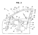
- Fig. 3 shows the door 30 with the hole seal 51, the upper lining 52 and the lining 53 shown in Fig. 2 removed.
- the run channel 44 shown in Fig. 3 has a front channel 57 which a front edge 61 of the door glass 45 slidably contacts, an upper channel 58 on which an upper edge 62 of the door glass 45 abuts, and a rear channel 59 which a rear edge 63 of the door glass 45 slidably contacts.
- the door glass 45 has the four edges consisting of the front edge 61, the upper edge 62, the rear edge 63 and a lower edge 64.
- the rear edge 63 has upper and lower projecting portions 65, 66 formed at upper and lower portions thereof, respectively, and projecting towards a rear part of the vehicle body 11.
- the upper projecting portion 65 and the lower projecting portion 66 are spaced from each other in an up-and-down direction.
- the upper and lower projecting portions 65, 66 are each small in length.
- the rear edge 63 of the door glass 45 is easily worked with increased precision in a short time, and the management for the working precision is easy to perform. Because the upper and lower projecting portions 65, 66 of the rear edge 63 of the door glass 45 slidably contact the rear channel 59 of the run channel 44, the door glass 45 can undergo a reduced resistance when sliding up and down.
- the upper projecting portion 65 has a peak portion 67 extending in a straight line along the rear channel 59 of the run channel 44 towards a middle portion of the rear edge 63 positioned centrally in an up-and-down direction of the rear edge 63.
- the rear edge 63 is beveled at a top end portion thereof, such that the top end portion of the rear edge 63 does project.
- the lower projecting portion 66 has a peak portion 68 extending in a straight line along the rear channel 59 of the run channel 44 towards the middle portion of the rear edge 63 positioned centrally in the up-and-down direction of the rear edge 63.
- the rear edge 63 is beveled at a bottom end portion thereof, such that the bottom end of the rear edge 63 does not project.
- the upper edge 62 of the door glass 45 is curved at a greater radius of curvature than the upper channel 58 curved, as will be set forth later.
- the upper edge 62 of the door glass 45 has an upper front end 71, an upper rear end 72 and a middle portion 73.
- the lower edge 64 has an attachment portion 69 projecting downwardly for attachment of the window regulator 46 thereto.
- the window regulator 46 includes a rail 74, a sliding member 75 slidably attached to the rail 74, forward and reverse cables 76, 77 connected to the sliding member 75 and a drive unit 78 for driving the cables 76, 77.
- the rail 74 is held to the door lower part 33 of the door body 31 by brackets 79, 79.
- the front sash 47 supports the front channel 57 while the center sash 48 supports the rear channel 59.
- Fig. 4 shows in cross-section an upper frame 82 of the window sash 32, the outer weatherstrip 34, the inner weatherstrip 35 and the upper channel 58 of the run channel 44.
- the inner weatherstrip 35 is attached to the upper frame 82 of the window sash 32 on a passenger compartment side of the vehicle 10 while the outer weatherstrip 34 is attached to the upper frame 82 of the window sash 32 on the outside of the vehicle 10.
- the inner weatherstrip 35 has a hollow portion 84 resiliently abutting on the vehicle body 11.
- the outer weatherstrip 34 has a projecting piece 85 resiliently abutting on the vehicle body 11.
- the upper channel 58 of the run channel 44 is attached to the upper frame 82 of the window sash 32 on the outside of the vehicle 11.
- the upper channel 58 has an upper projecting piece 87 resiliently abutting on an inner surface of the door glass 45.
- the upper edge 62 of the door glass 45 abuts on an upper hollow portion 86 of the upper channel 58 of the run channel 44.
- the upper channel 58 of the run channel 44 is in sealing engagement with the door glass 45.
- Fig. 5 shows in cross-section a front frame 81 of the window sash 32 and the front channel 57 of the run channel 44.
- the front channel 57 is received in an inner space defined by the front frame 81 of U-shaped cross-section.
- the front channel 57 has a front outer piece 91 resiliently abutting on an outer surface of the door glass 45.
- the front channel 57 has a front inner piece 92 flexed in abutment on the door glass 45.
- the front channel 57 seals a gap between the door glass (window pane) 45 and the window sash 32.
- Fig. 6 shows in cross-section a rear frame 83 of the window sash 32 and the rear channel 59 of the run channel 44.
- the rear channel 59 is received in an inner space defined by the rear frame 83 of U-shaped cross-section.
- the rear channel 59 has a rear outer piece 93 resiliently abutting on the outer surface of the door glass 45.
- the rear channel 59 has a front inner piece 94 flexed in abutment on the door glass 45.
- the rear channel 59 seals a gap between the door glass (window pane) 45 and the window sash 32.
- Fig. 7 shows the door 30 for the vehicle 10, especially, the door glass 45 in detail.
- the door glass 45 slides up and down along the front and rear channels 57, 59 of the run channel 44. By abutting on the upper channel 58 of the run channel 44, the door glass 45 fully closes a window defined by the window sash 32.
- the rear edge 63 of the door glass 45 in sliding contact with the rear channel 59 of the run channel 44 has the upper projecting portion 65 and the lower projecting portion 66 formed on a side of an upper end portion of the rear edge 63 and on a side of a lower end portion of the rear edge 63, respectively.
- the upper projecting portion 65 and the lower projecting portion 66 more project towards the rear part of the vehicle body 11 than the middle portion of the rear edge 63.
- a device or mechanism e.g., the window regulator 46 for driving the door glass 45 can be downsized for reducing a cost of the door 30.
- the peak portion 67 of the upper projecting portion 65 is connected through a beveled portion 63a to a top end of the rear edge 63 of the door glass 45.
- the peak portion 68 of the lower projecting portion 66 is connected through a beveled portion 63b to a bottom end of the rear edge 63 of the door glass 45.
- the upper projecting portion 65 has the upper beveled portion 63a and the peak portion 67 while the lower projecting portion 66 has the lower beveled portion 63b and the peak portion 68.
- the beveled portion 63a of the upper projecting portion 65 is an escape portion for enabling the top end of the rear edge 63 to avoid being caught by the rear channel 59 of the run channel 44 when the door glass 45 is inclined during the upward or downward slide movement.
- the beveled portion 63b of the lower projecting portion 66 is an escape portion for enabling the bottom end of the rear edge 63 to avoid being caught by the rear channel 59 of the run channel 44 when the door glass 45 is inclined during the upward or downward slide movement. Accordingly, even if the door glass 45 is inclined during the upward or downward slide movement, the door glass 45 can avoid being caught by the run channel 44 without contact resistance between the rear edge 63 of the door glass 45 and the rear channel 59 of the run channel 44 increasing. Therefore, the door glass 45 can smoothly slide up and down while undergoing a small resistance.
- the door glass 45 provides a stable, smooth slide movement with respect to the rear channel 59 while preventing a slide sound from being produced between the door glass 45 and the rear channel 59.
- the upper channel 58 of the run channel 44 is curved at an optionally selected radius of curvature.
- the middle portion 73 of the upper edge 62 of the door glass 45 is curved at a greater radius of curvature than the upper channel 58 of the run channel 44 such that the upper front end 71 and the upper rear end 72 abut on the upper channel 58 prior to the middle portion 73 when the door glass 45 is raised and fully closes the window defined by the window sash 32.
- the upper front end 71 and the upper rear end 72 of the upper edge 62 of the door glass 45 abut on the upper channel 58 of the run channel 44 prior to the middle portion 73, namely, because the upper edge 62 does not abut on the upper channel 58 in its entirety in one stroke, loud sound can be prevented from being produced when the door glass 45 fully closes the window defined by the window sash 32. Also, because the two portions, that is, the upper front end 71 and the upper rear end 72 abut on the upper channel 58 prior to the upper middle portion 73, the door glass 45 can be strongly pressed against the run channel 44. With this arrangement, quietness can be made within the passenger compartment of the vehicle 10.
- Fig. 8A and Fig. 8B illustrate the door glasses in the comparative example and in the one embodiment of the present invention and the door glasses of Fig. 8A and Fig. 8B are both in normal states where they are not inclined.
- Fig. 8C and Fig. 8D illustrate the door glasses in the comparative example and in the one embodiment of the present invention and the door glasses of Fig. 8C and Fig. 8D are both in inclined states.
- a vehicular door 170 in the comparative example of Fig. 8A includes a door glass 175 slidable up and down along a run channel 174.
- the door glass 175 has a flat rear edge 173 (extending in a straight line). That is, the rear edge 173 of the door glass 175 abuts on the run channel 174 throughout the length thereof. Thus, when the door glass 175 slides up and down along the run channel 174, a large slide resistance is produced between the door glass 175 and the run channel 174.
- the rear edge 63 of the door glass 45 in the embodiment of the present invention shown in Fig. 8B does not abut on the run channel 44 in its entirety because the rear edge 63 has the upper and lower projecting portions 65, 66.
- the peak portion 67 of the upper projecting portion 65 extends towards the middle portion of the rear edge 63 from a position spaced from the top end of the rear edge 63 of the door glass 45.
- the peak portion 68 of the lower projecting portion 66 extends towards the middle portion of the rear edge 63 from a position spaced from the bottom end of the rear edge 63 of the door glass 45.
- the peak portion 67 is formed by cutting the rear edge 63 by a predetermined distance from the top end of the rear edge 63 while the peak portion 68 is formed by cutting the rear edge 63 by a predetermined distance from the bottom end of the rear edge 63.
- Fig. 9 shows a door 130 for a vehicle according to another embodiment of the present invention.
- Reference numerals 131, 132, 133, 134, 135, 136, 137, 138, 139, 141, 142, 143, 144, 145, 146, 147, 148, 151, 152, 153, 154, 155 denote a door body, a window sash of the door body 131, a door lower part of the door body 131, an outer weatherstrip, an inner weatherstrip, an upper or lower hinge, a door checker, a speaker, an outer moulding, a door mirror garnish, a door mirror, a sash garnish, a run channel, a door glass, a window regulator (means for raising and lowering the door glass 145), a front sash, a center sash, a hole seal, an upper lining, a lining, an inner moulding and a drive unit for the window regulator 146, respectively.
- the window regulator 146 of the door 130 is an arm-type window regulator.
- the window regulator 146 supports the door glass 145 by holding two points of a lower edge 164 of the door glass 145, such that the door glass 145 can be inclined at a smaller angle when the door glass 145 slides up and down along the run channel 144.
- the door glass 145 has a front edge 161, an upper edge 162 and a rear edge 163 identical in configuration to the front edge 61, the upper edge 62 and the rear edge 63 of the door glass 45 shown in Fig. 7, respectively.
- the door for the vehicle according to the present invention can also be applicable to other vehicular doors than the right front door 30 which include a left front door, a left rear door and a right rear door each having a door glass slidable up and down along a run channel.
- the rear edge has the upper and lower projecting portions
- the door glass of the door for the vehicle according to the present invention may have the upper and lower projecting portions at the front edge 61 or both of the front and rear edges thereof.
- the door glass 45 includes the upper edge 62 formed to have a greater radius of curvature than the upper run channel 58 of the run channel 44, as shown in Fig. 7, so as to cause the upper front end 71 and the upper rear end 72 to abut on the upper channel 58 prior to the middle portion 73
- the upper edge 62 of the door glass 45 may be formed to have an upper front end 71 and an upper rear end 72 projecting more than a middle portion 73 or to provide a recessed portion of the middle portion 73 to abut on the upper channel 58.
Abstract
Description
- The present invention relates to a door for a vehicle including a run channel and a door glass slidable up and down along the run channel.
- Doors for vehicles including run channels, door glasses movable up and down along the run channels, and window regulators provided at lower parts of the door glasses are put in practical use.
- As for the above door, no serious problem is presented in its practical use so long as the door glass of the door has a front edge, an upper edge and a rear edge formed to conform in configuration to three sides, that is, a front channel, an upper channel and a rear channel of the run channel, respectively.
- The door as discussed above is disclosed in, for example, JP-A-11-348556. The disclosed door will be described with reference to Fig. 10 hereof.
- A
door 200 for a vehicle shown in Fig. 10 includes adoor body 201, arun channel 202 provided in thedoor body 201 and adoor glass 203 movable up and down along therun channel 202. Thedoor glass 203 has a lower part at which awindow regulator 204 is positioned. Thewindow regulator 204 is attached to thedoor body 201. Thedoor glass 203 has afront edge 211, anupper edge 212 and arear edge 213 conforming in configuration to afront channel 205, anupper channel 206 and arear channel 207 of therun channel 202, respectively. - The
front edge 211 of thedoor glass 203 slides in its entirety relative to thefront channel 205. Therear edge 213 of thedoor glass 203 slides in its entirety relative to therear channel 207. Thus, thedoor glass 203 is undesirably subjected to an increased resistance when sliding up and down along therun channel 202. - Additionally, because the
upper edge 212 of thedoor glass 203 has its configuration conforming to that of theupper channel 206 of therun channel 202, theupper edge 212 is in its entirety fitted to theupper channel 206 in one stroke when thedoor glass 203 is fully closed. As a result, thedoor glass 203 can not be fully closed without producing a loud sound. - Thus, there has been a demand for a vehicular door including a door glass which can undergo a reduced resistance when moving up and down and which can be fully closed without producing a loud sound.
- According to a first aspect of the present invention, there is provided a door for a vehicle, comprising: a door body; a run channel provided in the door body; a door glass slidable up and down along a front channel and a rear channel of the run channel; and wherein a front edge of the door glass in sliding contact with the front channel and/or a rear edge of the door glass in sliding contact with the rear channel has projecting portions at upper and lower end portions thereof, the projecting portions projecting more than a middle portion of the front edge and/or the rear edge positioned centrally in an up-and-down direction of the front edge and/or the rear edge.
- By virtue of the upper and lower projecting portions thus arranged, the front edge and/or the rear edge of the door glass does not abut on the run channel throughout the length thereof. Thus, the door glass can undergo a reduced resistance when sliding up and down. Additionally, any member (e.g., means for raising and lowering the door glass, generally so-called a window regulator) for driving the door glass can be rendered small in size. Therefore, it becomes possible to reduce a cost of the door for the vehicle.
- In a preferred form of the present invention, peak portions of the upper and lower projecting portions extend towards the middle portion from positions spaced from top and bottom ends of the front edge and/or the rear edge of the door glass. More particularly, for example, beveled portions extend from the top and bottom ends of the front edge and/or the rear edge of the door glass to the positions spaced from the top and bottom ends of the front edge and/or the rear edge of the door glass. Thus, the door glass can smoothly slide up and down along the run channel without being caught by the run channel even if the door glass is inclined during the slide movement.
- Desirably, the peak portions of the upper and lower projecting portions each extend in a straight line along the front channel and/or the rear channel. Therefore, the door glass can stably slide relative to the run channel without producing a slide sound.
- According to a second aspect of the present invention, there is provided a door for a vehicle, comprising: a door body; a run channel provided in the door body; a door glass slidable up and down along a front channel and a rear channel of the run channel; and wherein an upper edge of the door glass is formed such that, when the upper edge abuts on an upper channel of the run channel, an upper front end and an upper rear end of the upper edge abut on the upper channel prior to an upper middle portion of the upper edge.
- More specifically, for example, in one embodiment, the upper channel of the run channel has an optionally selected radius of curvature, and the upper edge of the door glass has a radius of curvature greater than that of the upper channel. Accordingly, the upper front end and the upper rear end can abut on the upper channel of the run channel prior to the upper middle portion. With this arrangement, it becomes possible to prevent a loud sound from being produced when the door glass is fully closed. Additionally, because the upper front end and the upper rear end abut on the upper channel prior to the upper middle portion, the door glass can be strongly pressed against the run channel to thereby provide a silent passenger compartment.
- Certain preferred embodiments of the present invention will hereinafter be described in detail, by way of example only, with reference to the accompanying drawings, in which:
- Fig. 1 is a perspective view of a vehicle employing a door according to one embodiment of the present invention;
- Fig. 2 is an exploded perspective view of the door shown in Fig. 1;
- Fig. 3 is a side elevation view of the right front door of Fig. 2, as viewed from a passenger compartment side of the vehicle;
- Fig. 4 is a cross-sectional view taken along line 4-4 of Fig. 3;
- Fig. 5 is a cross-sectional view taken along line 5-5 of Fig. 3;
- Fig. 6 is a cross-sectional view taken along line 6-6 of Fig. 3;
- Fig. 7 is a view showing a configuration of a door glass of the door shown in Fig. 3;
- Fig. 8A through Fig. 8D are views showing a relation between each of door glasses in the one embodiment and a comparative example and the corresponding run channel for comparing the door glass in the one embodiment with the door glass in the comparative example;
- Fig. 9 is an exploded perspective view of a door for a vehicle according to another embodiment of the present invention; and
- Fig. 10 shows a conventional door for a vehicle;
-
- In Fig. 1,
reference numerals front door 30 will be hereinafter referred to as "adoor 30 for avehicle 10" according to one embodiment of the present invention. Thedoor 30 for thevehicle 10 will be discussed in detain below. - As shown in Fig. 2, the
door 30 for thevehicle 10 includes adoor body 31, arun channel 44 to be attached to thedoor body 31 from inside the same, and adoor glass 45 in sliding contact with therun channel 44. - The
door body 31 has awindow sash 32 and a doorlower part 33 located below thewindow sash 32. Thewindow sash 32 has its outside to which anouter weatherstrip 34 is attached. Thedoor body 31 has its inner periphery along which aninner weatherstrip 35 is attached. - Upper and
lower hinges door body 31 for allowing thedoor body 31 to move between an opened position and a closed position. Adoor checker 37 is disposed between theupper hinge 36 and thelower hinge 36 and attached to thedoor body 31. - A
speaker 38 is attached to the inside of thedoor body 31. - An
outer moulding 39 is attached to the outside of thedoor body 31. - A
door mirror 42 is attached via adoor mirror garnish 41 to the outside of thedoor body 31. - A
sash garnish 43 is attached to the outside of thewindow sash 32. - The
run channel 44 is provided in thedoor body 31. Thedoor glass 45 is slidable along therun channel 44. - Means 46 for raising and lowering the
door glass 45 is attached to thedoor body 31. This means 46 will be referred to as "window regulator 46" hereinbelow. - The
run channel 44 has its front part supported by afront sash 47 while therun channel 44 has its rear part supported by acenter sash 48. - The door
lower part 33 of thedoor body 31 has its inside covered by anupper lining 52 and alining 53 through ahole seal 51. Theupper lining 52 is covered by aninner moulding 54. - Fig. 3 shows the
door 30 with thehole seal 51, theupper lining 52 and thelining 53 shown in Fig. 2 removed. - The
run channel 44 shown in Fig. 3 has afront channel 57 which afront edge 61 of thedoor glass 45 slidably contacts, anupper channel 58 on which anupper edge 62 of thedoor glass 45 abuts, and arear channel 59 which arear edge 63 of thedoor glass 45 slidably contacts. - The
door glass 45 has the four edges consisting of thefront edge 61, theupper edge 62, therear edge 63 and alower edge 64. Therear edge 63 has upper and lower projectingportions vehicle body 11. The upper projectingportion 65 and the lower projectingportion 66 are spaced from each other in an up-and-down direction. The upper and lower projectingportions rear edge 63 of thedoor glass 45 is easily worked with increased precision in a short time, and the management for the working precision is easy to perform. Because the upper and lower projectingportions rear edge 63 of thedoor glass 45 slidably contact therear channel 59 of therun channel 44, thedoor glass 45 can undergo a reduced resistance when sliding up and down. - The upper projecting
portion 65 has apeak portion 67 extending in a straight line along therear channel 59 of therun channel 44 towards a middle portion of therear edge 63 positioned centrally in an up-and-down direction of therear edge 63. Therear edge 63 is beveled at a top end portion thereof, such that the top end portion of therear edge 63 does project. Similarly, the lower projectingportion 66 has apeak portion 68 extending in a straight line along therear channel 59 of therun channel 44 towards the middle portion of therear edge 63 positioned centrally in the up-and-down direction of therear edge 63. Therear edge 63 is beveled at a bottom end portion thereof, such that the bottom end of therear edge 63 does not project. - The
upper edge 62 of thedoor glass 45 is curved at a greater radius of curvature than theupper channel 58 curved, as will be set forth later. - The
upper edge 62 of thedoor glass 45 has an upperfront end 71, an upperrear end 72 and amiddle portion 73. Thelower edge 64 has anattachment portion 69 projecting downwardly for attachment of thewindow regulator 46 thereto. - The
window regulator 46 includes arail 74, a slidingmember 75 slidably attached to therail 74, forward and reversecables member 75 and adrive unit 78 for driving thecables rail 74 is held to the doorlower part 33 of thedoor body 31 bybrackets - The
front sash 47 supports thefront channel 57 while thecenter sash 48 supports therear channel 59. - Fig. 4 shows in cross-section an
upper frame 82 of thewindow sash 32, theouter weatherstrip 34, theinner weatherstrip 35 and theupper channel 58 of therun channel 44. - The
inner weatherstrip 35 is attached to theupper frame 82 of thewindow sash 32 on a passenger compartment side of thevehicle 10 while theouter weatherstrip 34 is attached to theupper frame 82 of thewindow sash 32 on the outside of thevehicle 10. Theinner weatherstrip 35 has ahollow portion 84 resiliently abutting on thevehicle body 11. Theouter weatherstrip 34 has a projectingpiece 85 resiliently abutting on thevehicle body 11. Thus, the twoweatherstrips vehicle body 11 to prevent wind and rain from entering into a gap between thevehicle body 11 and theupper frame 82 of thewindow sash 32. - The
upper channel 58 of therun channel 44 is attached to theupper frame 82 of thewindow sash 32 on the outside of thevehicle 11. Theupper channel 58 has an upper projectingpiece 87 resiliently abutting on an inner surface of thedoor glass 45. Theupper edge 62 of thedoor glass 45 abuts on an upperhollow portion 86 of theupper channel 58 of therun channel 44. Thus, theupper channel 58 of therun channel 44 is in sealing engagement with thedoor glass 45. - Fig. 5 shows in cross-section a
front frame 81 of thewindow sash 32 and thefront channel 57 of therun channel 44. - The
front channel 57 is received in an inner space defined by thefront frame 81 of U-shaped cross-section. Thefront channel 57 has a frontouter piece 91 resiliently abutting on an outer surface of thedoor glass 45. Thefront channel 57 has a frontinner piece 92 flexed in abutment on thedoor glass 45. Thus, thefront channel 57 seals a gap between the door glass (window pane) 45 and thewindow sash 32. - Fig. 6 shows in cross-section a
rear frame 83 of thewindow sash 32 and therear channel 59 of therun channel 44. - The
rear channel 59 is received in an inner space defined by therear frame 83 of U-shaped cross-section. Therear channel 59 has a rearouter piece 93 resiliently abutting on the outer surface of thedoor glass 45. Therear channel 59 has a frontinner piece 94 flexed in abutment on thedoor glass 45. Thus, therear channel 59 seals a gap between the door glass (window pane) 45 and thewindow sash 32. - Fig. 7 shows the
door 30 for thevehicle 10, especially, thedoor glass 45 in detail. Thedoor glass 45 slides up and down along the front andrear channels run channel 44. By abutting on theupper channel 58 of therun channel 44, thedoor glass 45 fully closes a window defined by thewindow sash 32. Therear edge 63 of thedoor glass 45 in sliding contact with therear channel 59 of therun channel 44 has the upper projectingportion 65 and the lower projectingportion 66 formed on a side of an upper end portion of therear edge 63 and on a side of a lower end portion of therear edge 63, respectively. The upper projectingportion 65 and the lower projectingportion 66 more project towards the rear part of thevehicle body 11 than the middle portion of therear edge 63. - That is, only the upper and lower projecting
portions rear edge 63 substantially slidably contact therear channel 59 of therun channel 44. With this arrangement, a resistance which thedoor glass 45 undergoes when sliding up and down can be reduced. Accordingly, a device or mechanism (e.g., the window regulator 46) for driving thedoor glass 45 can be downsized for reducing a cost of thedoor 30. - The
peak portion 67 of the upper projectingportion 65 is connected through abeveled portion 63a to a top end of therear edge 63 of thedoor glass 45. Thepeak portion 68 of the lower projectingportion 66 is connected through abeveled portion 63b to a bottom end of therear edge 63 of thedoor glass 45. Namely, the upper projectingportion 65 has the upperbeveled portion 63a and thepeak portion 67 while the lower projectingportion 66 has the lowerbeveled portion 63b and thepeak portion 68. Thebeveled portion 63a of the upper projectingportion 65 is an escape portion for enabling the top end of therear edge 63 to avoid being caught by therear channel 59 of therun channel 44 when thedoor glass 45 is inclined during the upward or downward slide movement. Similarly, thebeveled portion 63b of the lower projectingportion 66 is an escape portion for enabling the bottom end of therear edge 63 to avoid being caught by therear channel 59 of therun channel 44 when thedoor glass 45 is inclined during the upward or downward slide movement. Accordingly, even if thedoor glass 45 is inclined during the upward or downward slide movement, thedoor glass 45 can avoid being caught by therun channel 44 without contact resistance between therear edge 63 of thedoor glass 45 and therear channel 59 of therun channel 44 increasing. Therefore, thedoor glass 45 can smoothly slide up and down while undergoing a small resistance. - Because the
peak portions portions rear edge 63 of thedoor glass 45 each extend in a straight line along therear channel 59 of therun channel 44, as discussed above, thedoor glass 45 provides a stable, smooth slide movement with respect to therear channel 59 while preventing a slide sound from being produced between thedoor glass 45 and therear channel 59. - The
upper channel 58 of therun channel 44 is curved at an optionally selected radius of curvature. Themiddle portion 73 of theupper edge 62 of thedoor glass 45 is curved at a greater radius of curvature than theupper channel 58 of therun channel 44 such that the upperfront end 71 and the upperrear end 72 abut on theupper channel 58 prior to themiddle portion 73 when thedoor glass 45 is raised and fully closes the window defined by thewindow sash 32. - Because the upper
front end 71 and the upperrear end 72 of theupper edge 62 of thedoor glass 45 abut on theupper channel 58 of therun channel 44 prior to themiddle portion 73, namely, because theupper edge 62 does not abut on theupper channel 58 in its entirety in one stroke, loud sound can be prevented from being produced when thedoor glass 45 fully closes the window defined by thewindow sash 32. Also, because the two portions, that is, the upperfront end 71 and the upperrear end 72 abut on theupper channel 58 prior to the uppermiddle portion 73, thedoor glass 45 can be strongly pressed against therun channel 44. With this arrangement, quietness can be made within the passenger compartment of thevehicle 10. - The
door glass 45 of thedoor 30 according to the present invention will be discussed in comparison with a door glass in a comparative example. Fig. 8A and Fig. 8B illustrate the door glasses in the comparative example and in the one embodiment of the present invention and the door glasses of Fig. 8A and Fig. 8B are both in normal states where they are not inclined. Fig. 8C and Fig. 8D illustrate the door glasses in the comparative example and in the one embodiment of the present invention and the door glasses of Fig. 8C and Fig. 8D are both in inclined states. - A
vehicular door 170 in the comparative example of Fig. 8A includes adoor glass 175 slidable up and down along arun channel 174. Thedoor glass 175 has a flat rear edge 173 (extending in a straight line). That is, therear edge 173 of thedoor glass 175 abuts on therun channel 174 throughout the length thereof. Thus, when thedoor glass 175 slides up and down along therun channel 174, a large slide resistance is produced between thedoor glass 175 and therun channel 174. - In contrast, the
rear edge 63 of thedoor glass 45 in the embodiment of the present invention shown in Fig. 8B does not abut on therun channel 44 in its entirety because therear edge 63 has the upper and lower projectingportions door glass 45 slides up and down along therun channel 44, a smaller slide resistance is produced between thedoor glass 45 and therun channel 44 than between thedoor glass 175 and therun channel 174. Thus, thedoor glass 45 can be smoothly raised and lowered along therun channel 44. - When the
door glass 175 is inclined as indicated by an arrow a1, as shown in Fig. 8C, during the upward or downward slide movement, the rear edge 173 (especially, a corner portion) of thedoor glass 175 shown by a double dot-and-dash line strongly hits therun channel 174 with the result that thedoor glass 175 is caught by therun channel 174. - In the
door glass 45 of the embodiment of the present invention shown in Fig. 8D, thepeak portion 67 of the upper projectingportion 65 extends towards the middle portion of therear edge 63 from a position spaced from the top end of therear edge 63 of thedoor glass 45. Similarly, thepeak portion 68 of the lower projectingportion 66 extends towards the middle portion of therear edge 63 from a position spaced from the bottom end of therear edge 63 of thedoor glass 45. In other words, thepeak portion 67 is formed by cutting therear edge 63 by a predetermined distance from the top end of therear edge 63 while thepeak portion 68 is formed by cutting therear edge 63 by a predetermined distance from the bottom end of therear edge 63. With this arrangement, even if thedoor glass 45 is inclined as indicated by an arrow a2 of Fig. 8D during the upward or downward slide movement, the top or bottom end, especially, a top or bottom corner of therear edge 63 can avoid being caught by therun channel 44. This arrangement of the upper end lower projectingportions door glass 45. - Fig. 9 shows a
door 130 for a vehicle according to another embodiment of the present invention.Reference numerals door body 131, a door lower part of thedoor body 131, an outer weatherstrip, an inner weatherstrip, an upper or lower hinge, a door checker, a speaker, an outer moulding, a door mirror garnish, a door mirror, a sash garnish, a run channel, a door glass, a window regulator (means for raising and lowering the door glass 145), a front sash, a center sash, a hole seal, an upper lining, a lining, an inner moulding and a drive unit for thewindow regulator 146, respectively. - The
window regulator 146 of thedoor 130 is an arm-type window regulator. Thewindow regulator 146 supports thedoor glass 145 by holding two points of alower edge 164 of thedoor glass 145, such that thedoor glass 145 can be inclined at a smaller angle when thedoor glass 145 slides up and down along therun channel 144. - The
door glass 145 has afront edge 161, anupper edge 162 and arear edge 163 identical in configuration to thefront edge 61, theupper edge 62 and therear edge 63 of thedoor glass 45 shown in Fig. 7, respectively. - The door for the vehicle according to the present invention can also be applicable to other vehicular doors than the right
front door 30 which include a left front door, a left rear door and a right rear door each having a door glass slidable up and down along a run channel. - In the illustrated embodiments, the rear edge has the upper and lower projecting portions, however, the door glass of the door for the vehicle according to the present invention may have the upper and lower projecting portions at the
front edge 61 or both of the front and rear edges thereof. - Although, in the illustrated embodiment, the
door glass 45 includes theupper edge 62 formed to have a greater radius of curvature than theupper run channel 58 of therun channel 44, as shown in Fig. 7, so as to cause the upperfront end 71 and the upperrear end 72 to abut on theupper channel 58 prior to themiddle portion 73, theupper edge 62 of thedoor glass 45 may be formed to have an upperfront end 71 and an upperrear end 72 projecting more than amiddle portion 73 or to provide a recessed portion of themiddle portion 73 to abut on theupper channel 58.
Claims (6)
- A door (30) for a vehicle (10), comprising:wherein a front edge (61) of the door glass in sliding contact with the front channel and/or a rear edge (63) of the door glass in sliding contact with the rear channel (59) has projecting portions (65, 66) at upper and lower end portions thereof, the projecting portions projecting more than a vertically middle portion of the front edge and/or the rear edge.a door body (31);a run channel (44) provided in the door body; anda door glass (45) slidable up and down along a front channel (57) and a rear channel (59) of the run channel,
- A door for a vehicle according to claim 1, wherein peak portions (67, 68) of the upper and lower projecting portions (65, 66) extend towards the middle portion from positions spaced from top and bottom ends of the front edge (61) and/or the rear edge (63) of the door glass.
- A door for a vehicle according to claim 2, wherein the peak portions (67, 68) of the upper and lower projecting portions (65, 66) extend straight along the front channel and/or the rear channel.
- A door for a vehicle according to claim 2, wherein beveled portions (63a, 63b) extend from the top and bottom ends of the front edge and/or the rear edge of the door glass to the positions spaced from the top and bottom ends of the front edge and/or the rear edge of the door glass.
- A door for a vehicle, comprising:wherein an upper edge (62) of the door glass is formed such that, when the upper edge abuts on an upper channel (58) of the run channel, an upper front end (71) and an upper rear end (72) of the upper edge abut on the upper channel prior to an upper middle portion (73) of the upper edge.a door body (31);a run channel (44) provided in the door body; anda door glass (45) slidable up and down along a front channel (57) and a rear channel (59) of the run channel,
- A door for a vehicle according to claim 5, wherein the upper channel (58) of the run channel has an optionally selected radius of curvature, the upper edge (62) of the door glass having a radius of curvature greater than that of the upper channel.
Applications Claiming Priority (2)
| Application Number | Priority Date | Filing Date | Title |
|---|---|---|---|
| JP2004028511A JP3866720B2 (en) | 2004-02-04 | 2004-02-04 | Vehicle door |
| JP2004028511 | 2004-02-04 |
Publications (3)
| Publication Number | Publication Date |
|---|---|
| EP1561619A2 true EP1561619A2 (en) | 2005-08-10 |
| EP1561619A3 EP1561619A3 (en) | 2005-08-17 |
| EP1561619B1 EP1561619B1 (en) | 2009-04-01 |
Family
ID=34675508
Family Applications (1)
| Application Number | Title | Priority Date | Filing Date |
|---|---|---|---|
| EP05002276A Expired - Fee Related EP1561619B1 (en) | 2004-02-04 | 2005-02-03 | Vehicle door with slidable window glass |
Country Status (5)
| Country | Link |
|---|---|
| US (1) | US7392618B2 (en) |
| EP (1) | EP1561619B1 (en) |
| JP (1) | JP3866720B2 (en) |
| CN (1) | CN100532774C (en) |
| DE (1) | DE602005013590D1 (en) |
Cited By (4)
| Publication number | Priority date | Publication date | Assignee | Title |
|---|---|---|---|---|
| CN101934705B (en) * | 2009-08-21 | 2012-05-23 | 上汽通用五菱汽车股份有限公司 | Assembling auxiliary structure and assembling method of car door glass lifter |
| WO2012112083A1 (en) * | 2011-02-15 | 2012-08-23 | Volvo Lastvagnar Ab | Vehicle door and method for mounting a window glass in a vehicle door |
| FR2971974A1 (en) * | 2011-02-24 | 2012-08-31 | Peugeot Citroen Automobiles Sa | Side door for motor vehicle, has movable glass pane whose upper edge comprises projecting portions that create predetermined gap between bottom of joint and bottom of sliding frame in upper edge zones formed between projecting portions |
| CN107856509A (en) * | 2016-09-21 | 2018-03-30 | 白木工业株式会社 | Vehicle door frame |
Families Citing this family (10)
| Publication number | Priority date | Publication date | Assignee | Title |
|---|---|---|---|---|
| US20070084130A1 (en) * | 2005-10-19 | 2007-04-19 | Gaustad Mark D | Channel Assembly for a Vehicle Window |
| JP4221003B2 (en) * | 2006-01-26 | 2009-02-12 | 本田技研工業株式会社 | Vehicle rear door structure |
| JP4388048B2 (en) * | 2006-09-27 | 2009-12-24 | 本田技研工業株式会社 | Garnish for vehicles |
| US8397433B2 (en) * | 2008-12-22 | 2013-03-19 | Toyota Motor Engineering & Manufacturing North America, Inc. | Rear edge side window catch assemblies for vehicles |
| US20100212231A1 (en) | 2009-02-20 | 2010-08-26 | Phillips Donald R | Automotive door with shatter-resistant movable side window for enhanced occupant retention |
| CN102022062B (en) * | 2010-11-11 | 2014-05-07 | 奇瑞汽车股份有限公司 | Clamping part for frameless vehicle door and window glass |
| DE102018201528B4 (en) * | 2018-02-01 | 2023-08-03 | Bayerische Motoren Werke Aktiengesellschaft | Motor vehicle side window arrangement and motor vehicle equipped therewith |
| CN108544904A (en) * | 2018-04-20 | 2018-09-18 | 上海蓥石汽车技术有限公司 | A kind of automotive back door glass assembly with glass of sliding lifting |
| KR20210018656A (en) * | 2019-08-08 | 2021-02-18 | 현대자동차주식회사 | Door frame for vehicle |
| US20220063812A1 (en) * | 2020-09-03 | 2022-03-03 | Tia A. Ryan | Protective shield system for public transportation |
Citations (6)
| Publication number | Priority date | Publication date | Assignee | Title |
|---|---|---|---|---|
| GB438766A (en) * | 1934-03-31 | 1935-11-22 | Automobile Ventilation Inc | Improvements in or relating to vehicle windows |
| DE1210691B (en) * | 1958-05-19 | 1966-02-10 | Wilmot Breeden Ltd | Sliding guide for a retractable window pane of a motor vehicle door |
| FR2339048A1 (en) * | 1976-01-21 | 1977-08-19 | Renault | Flat vehicle window control mechanism - has lever on horizontal axis with jaws gripping bar fixed to lower edge of pane |
| DE10030195A1 (en) * | 2000-06-19 | 2002-01-03 | Brose Fahrzeugteile | Motor vehicle door has window lifter to raise/lower window pane and move around all other door accessories without jamming |
| US6502365B1 (en) * | 1996-09-12 | 2003-01-07 | Ppg Industries Glass Sa | Assembly method and installation, a device assembled thereby, and a unit including the device |
| DE10302429A1 (en) * | 2003-01-17 | 2004-08-05 | Sai Automotive Sal Gmbh | Window arrangement for motor vehicles with a sliding window pane |
Family Cites Families (7)
| Publication number | Priority date | Publication date | Assignee | Title |
|---|---|---|---|---|
| US2025272A (en) * | 1934-03-31 | 1935-12-24 | Automobile Ventilation Inc | Ventilating apparatus for vehicle bodies |
| JPS6130517A (en) | 1984-07-20 | 1986-02-12 | Nichiban Co Ltd | Application drug for mucosa consisting of multilayer structure |
| IT1237689B (en) * | 1989-12-15 | 1993-06-15 | Fiat Auto Spa | DOOR FOR VEHICLES AND METHOD FOR THE REALIZATION OF THE SAME. |
| US5050348A (en) * | 1990-07-16 | 1991-09-24 | Donnelly Corporation | Panel and bracket assembly and method for making same |
| US5243785A (en) * | 1991-03-19 | 1993-09-14 | Donnelly Corporation | Panel assembly for vehicles with molded regulator attachment |
| JPH11348556A (en) | 1998-06-15 | 1999-12-21 | Asahi Glass Co Ltd | Door for automobile |
| US6018913A (en) * | 1998-12-07 | 2000-02-01 | Hi-Lex Corporation | Sliding window with improved closure |
-
2004
- 2004-02-04 JP JP2004028511A patent/JP3866720B2/en not_active Expired - Fee Related
-
2005
- 2005-02-02 CN CNB2005100053423A patent/CN100532774C/en not_active Expired - Fee Related
- 2005-02-02 US US11/048,982 patent/US7392618B2/en not_active Expired - Fee Related
- 2005-02-03 EP EP05002276A patent/EP1561619B1/en not_active Expired - Fee Related
- 2005-02-03 DE DE602005013590T patent/DE602005013590D1/en active Active
Patent Citations (6)
| Publication number | Priority date | Publication date | Assignee | Title |
|---|---|---|---|---|
| GB438766A (en) * | 1934-03-31 | 1935-11-22 | Automobile Ventilation Inc | Improvements in or relating to vehicle windows |
| DE1210691B (en) * | 1958-05-19 | 1966-02-10 | Wilmot Breeden Ltd | Sliding guide for a retractable window pane of a motor vehicle door |
| FR2339048A1 (en) * | 1976-01-21 | 1977-08-19 | Renault | Flat vehicle window control mechanism - has lever on horizontal axis with jaws gripping bar fixed to lower edge of pane |
| US6502365B1 (en) * | 1996-09-12 | 2003-01-07 | Ppg Industries Glass Sa | Assembly method and installation, a device assembled thereby, and a unit including the device |
| DE10030195A1 (en) * | 2000-06-19 | 2002-01-03 | Brose Fahrzeugteile | Motor vehicle door has window lifter to raise/lower window pane and move around all other door accessories without jamming |
| DE10302429A1 (en) * | 2003-01-17 | 2004-08-05 | Sai Automotive Sal Gmbh | Window arrangement for motor vehicles with a sliding window pane |
Cited By (5)
| Publication number | Priority date | Publication date | Assignee | Title |
|---|---|---|---|---|
| CN101934705B (en) * | 2009-08-21 | 2012-05-23 | 上汽通用五菱汽车股份有限公司 | Assembling auxiliary structure and assembling method of car door glass lifter |
| WO2012112083A1 (en) * | 2011-02-15 | 2012-08-23 | Volvo Lastvagnar Ab | Vehicle door and method for mounting a window glass in a vehicle door |
| FR2971974A1 (en) * | 2011-02-24 | 2012-08-31 | Peugeot Citroen Automobiles Sa | Side door for motor vehicle, has movable glass pane whose upper edge comprises projecting portions that create predetermined gap between bottom of joint and bottom of sliding frame in upper edge zones formed between projecting portions |
| CN107856509A (en) * | 2016-09-21 | 2018-03-30 | 白木工业株式会社 | Vehicle door frame |
| CN107856509B (en) * | 2016-09-21 | 2022-03-01 | 白木工业株式会社 | Door frame for vehicle |
Also Published As
| Publication number | Publication date |
|---|---|
| JP2005219582A (en) | 2005-08-18 |
| JP3866720B2 (en) | 2007-01-10 |
| US7392618B2 (en) | 2008-07-01 |
| EP1561619B1 (en) | 2009-04-01 |
| US20050166460A1 (en) | 2005-08-04 |
| EP1561619A3 (en) | 2005-08-17 |
| CN100532774C (en) | 2009-08-26 |
| DE602005013590D1 (en) | 2009-05-14 |
| CN1651706A (en) | 2005-08-10 |
Similar Documents
| Publication | Publication Date | Title |
|---|---|---|
| US7392618B2 (en) | Door for vehicle having a door glass with projecting portions | |
| US4653230A (en) | Vehicle body structure | |
| JP6700900B2 (en) | Sealing material for automobile doors | |
| US20090072588A1 (en) | Vehicle sun roof system | |
| WO2020163488A1 (en) | Vehicle flush window system, a vehicle comprising same, and related assembly method | |
| US4842327A (en) | Convertible vehicle having dual rear quarter window assembly | |
| US4688847A (en) | Vehicle window installation | |
| EP2149468B1 (en) | Vehicle glass seal | |
| US11820210B2 (en) | Hidden division bar for a vehicle window | |
| US5495693A (en) | Vehicle door assembly | |
| US7062880B2 (en) | Stabilizer clip for window assembly | |
| US6971706B2 (en) | Side structure of a vehicle | |
| JPS6022198Y2 (en) | automotive glass launch channel | |
| JP3657570B2 (en) | Sunroof device deflector | |
| EP1084879A3 (en) | Sliding window for motor vehicles | |
| KR20200107801A (en) | Motor vehicle | |
| US10465428B2 (en) | Apparatus and method providing a full window opening above a door including a pivoting division bar | |
| JP2006232222A (en) | Door structure of vehicle | |
| CN111094035B (en) | Decorative part for door and window of vehicle | |
| CA1179839A (en) | Vehicle door conversion | |
| JPH06293220A (en) | Sunshade guide device for car sun-roof | |
| EP4292845A1 (en) | Sealing profile strand and sealing arrangement for a sliding window | |
| KR20090063822A (en) | Sun roof for vehicle | |
| US20030122406A1 (en) | Sunroof structure | |
| KR100422688B1 (en) | Guide rail structure of a door module for an automobile |
Legal Events
| Date | Code | Title | Description |
|---|---|---|---|
| PUAI | Public reference made under article 153(3) epc to a published international application that has entered the european phase |
Free format text: ORIGINAL CODE: 0009012 |
|
| PUAL | Search report despatched |
Free format text: ORIGINAL CODE: 0009013 |
|
| AK | Designated contracting states |
Kind code of ref document: A2 Designated state(s): AT BE BG CH CY CZ DE DK EE ES FI FR GB GR HU IE IS IT LI LT LU MC NL PL PT RO SE SI SK TR |
|
| AX | Request for extension of the european patent |
Extension state: AL BA HR LV MK YU |
|
| AK | Designated contracting states |
Kind code of ref document: A3 Designated state(s): AT BE BG CH CY CZ DE DK EE ES FI FR GB GR HU IE IS IT LI LT LU MC NL PL PT RO SE SI SK TR |
|
| AX | Request for extension of the european patent |
Extension state: AL BA HR LV MK YU |
|
| RIC1 | Information provided on ipc code assigned before grant |
Ipc: 7B 60J 1/17 A Ipc: 7B 60J 1/00 B |
|
| 17P | Request for examination filed |
Effective date: 20051011 |
|
| AKX | Designation fees paid |
Designated state(s): DE GB |
|
| GRAP | Despatch of communication of intention to grant a patent |
Free format text: ORIGINAL CODE: EPIDOSNIGR1 |
|
| RIN1 | Information on inventor provided before grant (corrected) |
Inventor name: WATANABE, HAKUREIC/O HONDA R&D CO., LTD. Inventor name: YAMAGUCHI, JIROC/O HONDA R&D CO., LTD. |
|
| RAP1 | Party data changed (applicant data changed or rights of an application transferred) |
Owner name: HONDA MOTOR CO., LTD. |
|
| GRAS | Grant fee paid |
Free format text: ORIGINAL CODE: EPIDOSNIGR3 |
|
| RAP1 | Party data changed (applicant data changed or rights of an application transferred) |
Owner name: HONDA MOTOR CO., LTD. |
|
| GRAA | (expected) grant |
Free format text: ORIGINAL CODE: 0009210 |
|
| AK | Designated contracting states |
Kind code of ref document: B1 Designated state(s): DE GB |
|
| REG | Reference to a national code |
Ref country code: GB Ref legal event code: FG4D |
|
| REF | Corresponds to: |
Ref document number: 602005013590 Country of ref document: DE Date of ref document: 20090514 Kind code of ref document: P |
|
| PLBE | No opposition filed within time limit |
Free format text: ORIGINAL CODE: 0009261 |
|
| STAA | Information on the status of an ep patent application or granted ep patent |
Free format text: STATUS: NO OPPOSITION FILED WITHIN TIME LIMIT |
|
| 26N | No opposition filed |
Effective date: 20100105 |
|
| REG | Reference to a national code |
Ref country code: DE Ref legal event code: R084 Ref document number: 602005013590 Country of ref document: DE |
|
| REG | Reference to a national code |
Ref country code: GB Ref legal event code: 746 Effective date: 20141114 |
|
| REG | Reference to a national code |
Ref country code: DE Ref legal event code: R084 Ref document number: 602005013590 Country of ref document: DE Effective date: 20141120 |
|
| PGFP | Annual fee paid to national office [announced via postgrant information from national office to epo] |
Ref country code: DE Payment date: 20150127 Year of fee payment: 11 |
|
| PGFP | Annual fee paid to national office [announced via postgrant information from national office to epo] |
Ref country code: GB Payment date: 20150128 Year of fee payment: 11 |
|
| REG | Reference to a national code |
Ref country code: DE Ref legal event code: R119 Ref document number: 602005013590 Country of ref document: DE |
|
| GBPC | Gb: european patent ceased through non-payment of renewal fee |
Effective date: 20160203 |
|
| PG25 | Lapsed in a contracting state [announced via postgrant information from national office to epo] |
Ref country code: GB Free format text: LAPSE BECAUSE OF NON-PAYMENT OF DUE FEES Effective date: 20160203 Ref country code: DE Free format text: LAPSE BECAUSE OF NON-PAYMENT OF DUE FEES Effective date: 20160901 |