EP1563288B1 - Messgerät zur bestimmung eines analyten in einer flüssigkeitsprobe unter verwendung von polymerelektronischen gerätekomponenten - Google Patents
Messgerät zur bestimmung eines analyten in einer flüssigkeitsprobe unter verwendung von polymerelektronischen gerätekomponenten Download PDFInfo
- Publication number
- EP1563288B1 EP1563288B1 EP03785515A EP03785515A EP1563288B1 EP 1563288 B1 EP1563288 B1 EP 1563288B1 EP 03785515 A EP03785515 A EP 03785515A EP 03785515 A EP03785515 A EP 03785515A EP 1563288 B1 EP1563288 B1 EP 1563288B1
- Authority
- EP
- European Patent Office
- Prior art keywords
- measuring apparatus
- test
- detector
- test element
- liquid sample
- Prior art date
- Legal status (The legal status is an assumption and is not a legal conclusion. Google has not performed a legal analysis and makes no representation as to the accuracy of the status listed.)
- Expired - Lifetime
Links
- 239000007788 liquid Substances 0.000 title claims abstract description 18
- 239000012491 analyte Substances 0.000 title claims abstract description 14
- 229920000642 polymer Polymers 0.000 title claims abstract description 13
- 238000012360 testing method Methods 0.000 claims abstract description 107
- 238000005259 measurement Methods 0.000 claims abstract description 32
- 238000011156 evaluation Methods 0.000 claims abstract description 16
- 238000003860 storage Methods 0.000 claims abstract description 6
- 238000001514 detection method Methods 0.000 claims abstract description 5
- 238000000034 method Methods 0.000 claims description 11
- 230000008569 process Effects 0.000 claims description 10
- 239000008280 blood Substances 0.000 claims description 5
- 210000004369 blood Anatomy 0.000 claims description 5
- 239000003990 capacitor Substances 0.000 claims description 4
- 230000007613 environmental effect Effects 0.000 claims description 3
- 230000006870 function Effects 0.000 claims description 3
- 230000004048 modification Effects 0.000 claims description 3
- 238000012986 modification Methods 0.000 claims description 3
- QVGXLLKOCUKJST-UHFFFAOYSA-N atomic oxygen Chemical compound [O] QVGXLLKOCUKJST-UHFFFAOYSA-N 0.000 claims description 2
- 229910052760 oxygen Inorganic materials 0.000 claims description 2
- 239000001301 oxygen Substances 0.000 claims description 2
- 238000004806 packaging method and process Methods 0.000 claims description 2
- XLYOFNOQVPJJNP-UHFFFAOYSA-N water Chemical compound O XLYOFNOQVPJJNP-UHFFFAOYSA-N 0.000 claims description 2
- 230000003213 activating effect Effects 0.000 claims 1
- 230000008859 change Effects 0.000 abstract description 6
- 239000004033 plastic Substances 0.000 abstract description 6
- 229920003023 plastic Polymers 0.000 abstract description 6
- 210000004027 cell Anatomy 0.000 description 11
- 238000004519 manufacturing process Methods 0.000 description 7
- 239000012530 fluid Substances 0.000 description 6
- 239000011888 foil Substances 0.000 description 4
- 238000007639 printing Methods 0.000 description 3
- 241001552669 Adonis annua Species 0.000 description 2
- WQZGKKKJIJFFOK-GASJEMHNSA-N Glucose Natural products OC[C@H]1OC(O)[C@H](O)[C@@H](O)[C@@H]1O WQZGKKKJIJFFOK-GASJEMHNSA-N 0.000 description 2
- 208000002193 Pain Diseases 0.000 description 2
- 238000010586 diagram Methods 0.000 description 2
- 238000005516 engineering process Methods 0.000 description 2
- 239000008103 glucose Substances 0.000 description 2
- 239000000758 substrate Substances 0.000 description 2
- 102000004190 Enzymes Human genes 0.000 description 1
- 108090000790 Enzymes Proteins 0.000 description 1
- 238000012369 In process control Methods 0.000 description 1
- JVTAAEKCZFNVCJ-UHFFFAOYSA-M Lactate Chemical compound CC(O)C([O-])=O JVTAAEKCZFNVCJ-UHFFFAOYSA-M 0.000 description 1
- WQZGKKKJIJFFOK-VFUOTHLCSA-N beta-D-glucose Chemical compound OC[C@H]1O[C@@H](O)[C@H](O)[C@@H](O)[C@@H]1O WQZGKKKJIJFFOK-VFUOTHLCSA-N 0.000 description 1
- 238000006243 chemical reaction Methods 0.000 description 1
- 239000011248 coating agent Substances 0.000 description 1
- 238000000576 coating method Methods 0.000 description 1
- 229920001940 conductive polymer Polymers 0.000 description 1
- 239000004020 conductor Substances 0.000 description 1
- 230000008878 coupling Effects 0.000 description 1
- 238000010168 coupling process Methods 0.000 description 1
- 238000005859 coupling reaction Methods 0.000 description 1
- 210000004544 dc2 Anatomy 0.000 description 1
- 239000003792 electrolyte Substances 0.000 description 1
- 230000036541 health Effects 0.000 description 1
- 230000001939 inductive effect Effects 0.000 description 1
- 208000015181 infectious disease Diseases 0.000 description 1
- 230000002458 infectious effect Effects 0.000 description 1
- 238000004190 ion pair chromatography Methods 0.000 description 1
- 238000010030 laminating Methods 0.000 description 1
- 239000004973 liquid crystal related substance Substances 0.000 description 1
- 239000000463 material Substances 0.000 description 1
- 244000005700 microbiome Species 0.000 description 1
- 239000011368 organic material Substances 0.000 description 1
- 238000003825 pressing Methods 0.000 description 1
- 238000011084 recovery Methods 0.000 description 1
- 239000000126 substance Substances 0.000 description 1
- 238000007725 thermal activation Methods 0.000 description 1
- 230000001960 triggered effect Effects 0.000 description 1
Images

Classifications
-
- A—HUMAN NECESSITIES
- A61—MEDICAL OR VETERINARY SCIENCE; HYGIENE
- A61B—DIAGNOSIS; SURGERY; IDENTIFICATION
- A61B5/00—Measuring for diagnostic purposes; Identification of persons
- A61B5/145—Measuring characteristics of blood in vivo, e.g. gas concentration, pH value; Measuring characteristics of body fluids or tissues, e.g. interstitial fluid, cerebral tissue
- A61B5/14532—Measuring characteristics of blood in vivo, e.g. gas concentration, pH value; Measuring characteristics of body fluids or tissues, e.g. interstitial fluid, cerebral tissue for measuring glucose, e.g. by tissue impedance measurement
-
- A—HUMAN NECESSITIES
- A61—MEDICAL OR VETERINARY SCIENCE; HYGIENE
- A61B—DIAGNOSIS; SURGERY; IDENTIFICATION
- A61B5/00—Measuring for diagnostic purposes; Identification of persons
- A61B5/15—Devices for taking samples of blood
- A61B5/150007—Details
- A61B5/150015—Source of blood
- A61B5/150022—Source of blood for capillary blood or interstitial fluid
-
- A—HUMAN NECESSITIES
- A61—MEDICAL OR VETERINARY SCIENCE; HYGIENE
- A61B—DIAGNOSIS; SURGERY; IDENTIFICATION
- A61B5/00—Measuring for diagnostic purposes; Identification of persons
- A61B5/15—Devices for taking samples of blood
- A61B5/150007—Details
- A61B5/150358—Strips for collecting blood, e.g. absorbent
-
- A—HUMAN NECESSITIES
- A61—MEDICAL OR VETERINARY SCIENCE; HYGIENE
- A61B—DIAGNOSIS; SURGERY; IDENTIFICATION
- A61B5/00—Measuring for diagnostic purposes; Identification of persons
- A61B5/15—Devices for taking samples of blood
- A61B5/150007—Details
- A61B5/150374—Details of piercing elements or protective means for preventing accidental injuries by such piercing elements
- A61B5/150381—Design of piercing elements
- A61B5/150412—Pointed piercing elements, e.g. needles, lancets for piercing the skin
-
- A—HUMAN NECESSITIES
- A61—MEDICAL OR VETERINARY SCIENCE; HYGIENE
- A61B—DIAGNOSIS; SURGERY; IDENTIFICATION
- A61B5/00—Measuring for diagnostic purposes; Identification of persons
- A61B5/15—Devices for taking samples of blood
- A61B5/150969—Low-profile devices which resemble patches or plasters, e.g. also allowing collection of blood samples for testing
-
- A—HUMAN NECESSITIES
- A61—MEDICAL OR VETERINARY SCIENCE; HYGIENE
- A61B—DIAGNOSIS; SURGERY; IDENTIFICATION
- A61B5/00—Measuring for diagnostic purposes; Identification of persons
- A61B5/15—Devices for taking samples of blood
- A61B5/151—Devices specially adapted for taking samples of capillary blood, e.g. by lancets, needles or blades
- A61B5/15101—Details
- A61B5/15103—Piercing procedure
- A61B5/15105—Purely manual piercing, i.e. the user pierces the skin without the assistance of any driving means or driving devices
-
- A—HUMAN NECESSITIES
- A61—MEDICAL OR VETERINARY SCIENCE; HYGIENE
- A61B—DIAGNOSIS; SURGERY; IDENTIFICATION
- A61B5/00—Measuring for diagnostic purposes; Identification of persons
- A61B5/15—Devices for taking samples of blood
- A61B5/151—Devices specially adapted for taking samples of capillary blood, e.g. by lancets, needles or blades
- A61B5/15142—Devices intended for single use, i.e. disposable
-
- A—HUMAN NECESSITIES
- A61—MEDICAL OR VETERINARY SCIENCE; HYGIENE
- A61B—DIAGNOSIS; SURGERY; IDENTIFICATION
- A61B5/00—Measuring for diagnostic purposes; Identification of persons
- A61B5/15—Devices for taking samples of blood
- A61B5/157—Devices characterised by integrated means for measuring characteristics of blood
-
- G—PHYSICS
- G01—MEASURING; TESTING
- G01N—INVESTIGATING OR ANALYSING MATERIALS BY DETERMINING THEIR CHEMICAL OR PHYSICAL PROPERTIES
- G01N33/00—Investigating or analysing materials by specific methods not covered by groups G01N1/00 - G01N31/00
- G01N33/48—Biological material, e.g. blood, urine; Haemocytometers
- G01N33/483—Physical analysis of biological material
- G01N33/487—Physical analysis of biological material of liquid biological material
- G01N33/48785—Electrical and electronic details of measuring devices for physical analysis of liquid biological material not specific to a particular test method, e.g. user interface or power supply
-
- A—HUMAN NECESSITIES
- A61—MEDICAL OR VETERINARY SCIENCE; HYGIENE
- A61B—DIAGNOSIS; SURGERY; IDENTIFICATION
- A61B2562/00—Details of sensors; Constructional details of sensor housings or probes; Accessories for sensors
- A61B2562/02—Details of sensors specially adapted for in-vivo measurements
- A61B2562/0295—Strip shaped analyte sensors for apparatus classified in A61B5/145 or A61B5/157
Definitions
- the invention relates to a measuring device for determining an analyte in a liquid sample, comprising the following device components: a test element with a test field for applying the liquid sample, wherein the test element undergoes a detectable change by the analyte to be determined, a detector which detects the change and in dependence an electrical detector signal generated therefrom, an evaluation circuit downstream of the detector, which evaluates the detector signal to a measurement result, a display device connected to the evaluation circuit for displaying the measurement result, and a power supply device for supplying power to the electrical device components.
- Such, from the US 6,300,141 known measuring device is formed on a support, for example in the shape and size of a credit card, and consists of a lower support member and a colored or transparent cover member, both of which may be plastic and connected to each other, for example glued, are. Between the lower support member and the cover are formed by the test element with the detector electrochemical biosensor, consisting of a microprocessor with memory existing evaluation circuit, the z. B. consisting of a liquid crystal display device, an operating element and arranged consisting of a solar cell or battery power supply device.
- the test field for applying the liquid sample contained in the cover part communicates with the biosensor via a fluid path, the fluid path and the biosensor being formed either in the lower support part or on a separate chip which can be attached to the support.
- biosensors can be used to determine multiple analytes in the fluid sample be provided, which are then connected via separate fluid paths with the one test field for applying the liquid sample.
- a comparable measuring device with electro-optical biosensor is from the U.S. 5,580,794 known. There are u. a also specified ways to calibrate the meter during or after its manufacture.
- the well-known card-shaped measuring devices enable analytical diagnoses in the fields of health, food and environment in a simple manner, with the result of the measurement being immediately readable from the card.
- the measurement result can also be stored on the card and read out by an external reader.
- the card-shaped meter may be a disposable item. Since the liquid path and optionally the biosensor after a successful measurement are no longer useful, then, if the liquid path and the biosensor are formed on the card itself, the whole card-shaped meter would be thrown away. However, for cost reasons, this can only be practiced if the measurements take place comparatively infrequently, ie only a few times a year.
- the invention is therefore based on the object ein.Efache and easy to handle and thereby inexpensive to allow determination of an analyte in a liquid sample.
- the above-mentioned object is achieved in that in the measuring device of the type specified, the electrical device components are at least partially formed on the basis of polymer electronics. Preferably, all electrical device components are formed on the basis of polymer electronics.
- the measuring device according to the invention is characterized particularly inexpensive to produce, so that it can be used, for example, as disposable for frequent, eg. B. daily, measurements is eligible.
- polymer electronics device components for example, in printing technology, for. Example, using polymers in solution (so-called electronic ink), on a flat support (card, film o. ⁇ .) Are applied.
- the complete measuring device can be applied to the carrier in a single printing process.
- all device components of the measuring device can be integrated on a support or it can be provided that the test field and the test element or the test field, the test element and the detector are formed in a first unit, which contains an interface to a further device components containing the other Device unit can be coupled.
- the device components of the first unit unit are then formed, for example, on a separate and thus interchangeable carrier, the.
- the device components of the measuring device according to the invention preferably further comprise a control device which controls the measuring process for the determination of the analyte.
- the control device may have means which are based on the actuation of a control element on the measuring device, for. B. a control knob on the removal of a Cover the meter or apply the liquid sample to the test field.
- the cover may be, for example, a film that the meter completely or partially, for. B. in the field of the test field and / or an electro-optical element (eg., Solar cell), covering and removing them electrically, for. B. by making or breaking a contact, or is detected optically.
- the cover which can seal the measuring device at least in the area of the test field against environmental influences such as water vapor and / or oxygen, can also consist of a packaging for the complete measuring device. Moreover, to protect the test field and the polymer electronics from light, the cover is preferably opaque. Is the removal of the cover, z. As film or coating, not provided before the intended use of the measuring device, the cover is at least partially, in particular in the region of the display device and serving as a power supply device solar cell, transparent.
- the control device also advantageously has means for preventing further measuring operations with one and the same test element, so that reuse or multiple use of an already used test element is precluded. If the meter only has a single test element, the reuse protection affects the complete meter. If the measuring device has a plurality of test elements, as will be explained in more detail below, then the reuse protection concerns firstly each individual test element and only when all test elements have been used does the measuring device itself also apply.
- the measuring device preferably has display means, which can be controlled by the control device for indicating the uselessness of the test element or the measuring device.
- the unusability is after a single use of the test element at the end of the relevant measurement process given.
- the unusability can be determined even when not yet used test element by detecting and evaluating given parameters of the test element, for example, its electrical conductivity,
- the display of uselessness can be done via the display device of the meter.
- the display can be bistable, ie switchable between an indicating state and a non-indicating state, energy being required only for the switching.
- the display can be effected, for example, by triggering a chemical reaction at a location of the measuring instrument by means of electrochemical or thermal activation, which results in a color change.
- the power supply device can consist of a solar cell or battery, preferably also in polymer electronics.
- the battery can be provided that the electrolyte only by a manual operation on the meter, z. B. pressing a control panel, tearing the package u. ⁇ ., Is brought into contact with the electrodes of the battery, so that the battery is formed only immediately before the use of the meter and so problems due to a discharge of the battery in the period between the production of Measuring device and its use are avoided. Since the measuring process takes place within a defined time, the power supply device preferably contains a rechargeable storage capacity which provides the energy required for the time of the measurement in a retrievable manner. The storage capacity, z.
- a double-layer capacitor (Super-Cap or Super Capacitor), for example, be charged by the solar cell or the battery directly or via a voltage converter to a defined voltage.
- the measurement can be triggered automatically or on request by the user, possibly after prior indication of the state of charge via the display device.
- the charging of the storage capacity can also be contacted from the outside or contactless, z. B. via inductive or capacitive coupling, done so that then can be dispensed with the solar cell or battery.
- a lancing aid in particular a needle or a spike, for integrating the blood sample is preferably integrated in the measuring device.
- the lancing device can be arranged outside the test field or the test fields, so that after the stinging the blood drops must be placed on the test field.
- the lancing device is arranged in or directly on the test field, so that with the stinging of the blood drops directly reaches the test field.
- At least one further test element with test field and detector is provided according to claim 1, wherein the detectors are connected via a selection circuit to the evaluation circuit.
- the selection circuit connects only one of the detectors and this only for single use with the evaluation circuit and selects after the measurement of a not yet used biosensor. Due to the multiple usability, the measuring device according to the invention can be far more cost-effective and more convenient for the user than a device that can be used only once. In this case, the selection circuit, which may be part of the control device, ensures that only a single and not yet used test element with its detector is connected to the evaluation circuit.
- the user can be shown the test field assigned to the respectively currently usable test element and subsequently, after using all existing test elements, the unusability of the measuring device.
- they can be covered with a cover to be removed before use, be covered in particular a film, with the already no longer existing cover indicates to the user, which test fields are no longer usable.
- the selection circuit can via detection means, for. As an interruptible electrical conductor loop detect the deducted covers so as to exclude already used, but also inadvertently or due to damage to the covers exposed test fields from further use.
- the selection circuit when it first detects the removal of a film, the associated detector - if this has not been selected - selects and excludes after a predetermined, sufficient for the measurement period of any further use.
- the selection circuit may comprise means which are based on the actuation of a control element on the measuring device, for. B. a control knob or to apply the liquid sample to one of the test fields and select the associated detector - if this has not yet been selected - for the measurement.
- the test fields in the edge region of the flat carrier are arranged in zones separated by break lines, wherein each zone can be broken off from the carrier after use of the test field located therein.
- the test fields in the zones are preferably arranged in such a way that they are covered by in each case one adjacent zone and are made accessible only by breaking off this adjacent zone. This ensures that the test fields can only be used successively in a predetermined sequence.
- the selection circuit can detect the aborted zones via detection means and thus recognize the still usable test fields.
- FIG. 1 shows a check card-shaped carrier 1 on which a test field 2 for applying a liquid sample are formed.
- the test field 2 communicates via a fluid path 3 or directly directly with a test element 4, which undergoes a detectable change by the analyte to be determined. This change is detected by means of a detector 5, for example optically or electrochemically, which generates an electrical detector signal in dependence thereon.
- a detector 5 for example optically or electrochemically, which generates an electrical detector signal in dependence thereon.
- the test element 4 for example, a responsive to the analyte biological or chemical component, eg. As an enzyme, an antibody or a microorganism
- the test element 4 and the detector 5 together form a so-called biosensor. Examples of such sensor structures are known from US Pat. No. 5,997,817 or the US Pat. No. 6,036,919 known. If more than one analyte is to be determined from the fluid sample, it is of course possible to provide additional test elements with detector
- the detector 5 is connected to an evaluation circuit 6, which evaluates the detector signal to a measurement result and this visualized by means of a display device 7.
- the control of the measuring process is carried out by a control device 8, which is connected to the detector 5, the evaluation circuit 6 and the display device 7.
- control element 9 By means of a likewise connected to the control device 8 control element 9, in the simplest case, a single control knob, basic functions of the meter, such. As switching on and off, reset, actuation of a reproduced on the display device 7 statement, etc., be exercised.
- the display device 7 can display to the user the operator actions to be performed in the form of a text or a pictogram and notify the functional status of the measuring device.
- the power supply of the electrical equipment components 5 to 9 is performed by a power supply device 10, preferably with a solar cell 11, the z. B. Piatzditen arranged under the display device 7 and can be illuminated by the passing through them ambient light.
- the power supply device 10 preferably contains a storage capacitor 12 which can be charged from the solar cell 11 to a defined voltage and which provides the energy required for the measuring process quickly and in a sufficient amount.
- the electrical device components 5 to 12 are all or at least partially, for example, with the exception of the power supply device 10 and / or the display device 7, formed in polymer electronics and z. B. printed on the plastic substrate 1.
- the carrier 1 with the device components formed thereon is covered with a cover 21, here in the form of a peelable film, which protects the device components 2 to 12 against external environmental influences.
- the cover 21 may be opaque, which on the one hand causes a light protection and on the other hand detecting the removal of the film 21 before the use of the meter by the solar cell 11 or other, not shown here, electro-optical detector element allows. If the cover 21 is provided as permanent protection even during the use of the measuring device, then it is transparent at least in the area of the display device 7 and the solar cell 11 and has an opening in the area of the test field 2.
- a lancing device here a mandrel 13, for integrating blood as a liquid sample is integrated on the carrier 1.
- the mandrel 13 can be arranged, for example, under a bubble-shaped cover over the test field 2, which yields against finger pressure against a mechanical bias, so that the mandrel 13 pierces the finger.
- the lancing device 13 ' which may consist of the material of the card-shaped carrier 1, may alternatively also be arranged in the vicinity of the test field 2.
- test field 2 may be formed with the test element 4 and possibly the detector 5 on a separate carrier 14 which is coupled via an interface 15 or 16 to the card-shaped carrier 1.
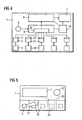
- FIG. 3 shows an example of the electrical circuit of the measuring device according to the invention.
- the evaluation circuit 6 has on the input side an amplifier 29, which amplifies its output voltage or converts the output current into a voltage depending on the type of the detector 5 and the detector signal generated by this.
- the voltage thus obtained is fed via a controllable switch 30 to an analog-to-digital converter (ADC) 31, here a dual-slope ADC, which generates a digital serial measurement result.
- ADC analog-to-digital converter
- This measurement result is clock-read via a gate 32 in a shift register 33, from where it is fed via a decoding logic 34 of the display device 7 and visualized there.
- the controllable switch 30 the input of the analog / digital converter 31 can be switched to a reference voltage U ref , which is provided here by the control device 8.
- the switch 30, as indicated by dashed lines, serve to select other detectors, as later in connection with FIG. 4
- the control device 8 controls the switch 30 and also generates a reset signal for the analog / digital converter 31 and the clock signal for the gate 32:
- control device 8 also controls the calibration of the measuring device by correcting the digital measurement result contained in the shift register 33 by means of a computing device 35 on the basis of calibration data contained in a calibration data memory 36.
- the calibration data memory 36 may be a programmable memory (eg EEPROM) in which the calibration data are contact-bound or contactlessly readable, for example by means of a transponder, or an electrical connection structure that can be changed by laser or other means. Because manufacturing conditions are not completely controllable, it is necessary to carry out a lot-specific calibration of the measuring instruments. As a rule, this is done by testing measuring instruments after completion on the basis of reference samples of known concentration and checking the recovery of the known concentration in the measurement result.
- test elements 17 with test fields 18 and detectors 19 are formed on the card-shaped carrier 1 in addition to the test element 4 with the test field 2 and the detector 5.
- the detectors 19 are connected to a selection circuit 20, the component the control device 8 is and always only one and still unused test element selects, connects the associated detector with the evaluation circuit 6 and selects a previously unused test element for the next measurement after the measurement.
- the evaluation circuit 6 evaluates the detector signal of each connected to her detector to a measurement result, which is visualized by means of the display device 7.
- the power supply of the electrical equipment components 5 to 9, 19 and 20 is carried out by the power supply device 10.
- the electrical equipment components 5 to 10, 19 and 20 are at least partially formed in polymer electronics and z. B. printed on the plastic substrate 1.
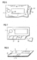
- FIG. 5 shows the view of an embodiment of the measuring device according to the invention, wherein the carrier 1 with the test fields 2, 18, the display device 7 and the control element 9 are visible.
- the test fields 2, 18 are each covered by peelable covers 21, here in the form of films.
- detection means 22 in the form of an interruptible line loop or the like are provided, which signal the selection circuit 20 as soon as a film has been removed or damaged.
- the underlying test field with the associated test element and detector can be selected for the measurement for a predetermined period of time. After expiration of this period of time and / or termination of the measurement, the relevant test element is blocked for future selection or use.
- Canceling the covers 24 may be similar to peeling off the sheets 21 'in the example FIG. 5 be detected.
- the display device 7 shows, here by an arrow 25, the test field selected for the next use, for. B. 2, to.
- the covers 24 may, as shown here, be sharp-edged, so that they can serve as a lancing device 13 "to the blood after breaking off.
- test fields 2, 18 are arranged on the edge of the card-shaped carrier 1 in zones 26 which are separated from one another by fault lines 27, so that the individual zones 26 are broken off the carrier 1 after use of the test fields, test elements and possibly detectors contained therein can not be used again. So that this really happens, the test fields 2, 18 are arranged in the regions of the fault lines 27 in each case to an adjacent zone 26, so that the test fields 2, 18 are made accessible only by breaking off this adjacent zone.
- the test fields 2, 18 are formed with the not visible here test elements and detectors on separate carrier films 28, which lie one above the other on the carrier 1 with the other device components, eg. B. 7 and 9, are applied.
- the carrier foils 28 can be pulled off one after the other, wherein only the test field on the uppermost carrier foil 28 can be used and the underlying test fields are protected.
- the carrier films 28 are plated through to the carrier 1 through. The removal of carrier films 28 can, as already explained above, be detected electrically or optically.
- the carrier films 28 may extend over the entire surface of the carrier 1 and are then transparent in the region of the display device 7 and the control knob 9.
Description
- Die Erfindung betrifft ein Messgerät zur Bestimmung eines Analyten in einer Flüssigkeitsprobe, mit folgenden Gerätekomponenten: ein Testelement mit einem Testfeld zur Aufbringung der Flüssigkeitsprobe, wobei das Testelement durch den zu bestimmenden Analyten eine detektierbare Veränderung erfährt, ein Detektor, der die Veränderung detektiert und in Abhängigkeit davon ein elektrisches Detektorsignal erzeugt, eine dem Detektor nachgeordnete Auswerteschaltung, die das Detektorsignal zu einem Messergebnis auswertet, eine an der Auswerteschaltung angeschlossene Anzeigevorrichtung zur Anzeige des Messergebnisses und eine Stromversorgungseinrichtung zur Stromversorgung der elektrischen Gerätekomponenten.
- Ein derartiges, aus der
US 6 300 141 bekanntes Messgerät ist auf einem Träger, beispielsweise in der Form und Größe einer Kreditkarte, ausgebildet und besteht aus einem unteren Trägerteil und einem farbigen oder durchsichtigen Abdeckteil, die beide aus Kunststoff sein können und miteinander verbunden, beispielsweise verklebt, sind. Zwischen dem unteren Trägerteil und dem Abdeckteil sind ein von dem Testelement mit dem Detektor gebildeter elektrochemischer Biosensor, die aus einem Mikroprozessor mit Speicher bestehende Auswerteschaltung, die z. B. aus einem Flüssigkristalldisplay bestehende Anzeigevorrichtung, ein Bedienelement sowie die aus einer Solarzelle oder Batterie bestehende Stromversorgungseinrichtung angeordnet. Das in dem Abdeckteil enthaltene Testfeld zur Aufbringung der Flüssigkeitsprobe kommuniziert über einen Flüssigkeitspfad mit dem Biosensor, wobei der Flüssigkeitspfad und der Biosensor entweder in dem unteren Trägerteil oder auf einem separaten Chip ausgebildet sind, der an dem Träger ansteckbar ist. Zur Bestimmung von mehreren Analyten in der Flüssigkeitsprobe können mehrere Biosensoren vorgesehen sein, die dann über getrennte Flüssigkeitspfade mit dem einen Testfeld zur Aufbringung der Flüssigkeitsprobe verbunden sind. - Ein vergleichbares Messgerät mit elektrooptischem Biosensor ist aus der
US 5 580 794 bekannt. Dort sind u. a auch Möglichkeiten angegeben, das Messgerät während oder nach seiner Herstellung zu kalibrieren. - Die bekannten kartenförmigen Messgeräte ermöglichen auf einfache Weise analytische Diagnosen in den Bereichen Gesundheit, Lebensmittel und Umwelt, wobei das Messergebnis unmittelbar von der Karte ablesbar ist. Darüber hinaus kann das Messergebnis auch auf der Karte gespeichert und durch ein externes Lesegerät ausgelesen werden. Bei dem kartenförmigen Messgerät kann es sich um einen Wegwerfartikel handeln. Da der Flüssigkeitspfad und gegebenenfalls der Biosensor nach einer erfolgten Messung nicht mehr zu gebrauchen sind, müsste dann, wenn der Flüssigkeitspfad und der Biosensor auf der Karte selbst ausgebildet sind, das ganze kartenförmige Messgerät weggeworfen werden. Dies ist jedoch aus Kostengründen nur dann praktizierbar, wenn die Messungen vergleichsweise selten, also nur wenige Male im Jahr, stattfinden.
- Der Erfindung liegt daher die Aufgabe zugrunde, eine.einfache und bequem handhabbare und dabei kostengünstige Bestimmung eines Analyten in einer Flüssigkeitsprobe zu ermöglichen.
- Wie aus dem Fraunhofer Magazin 4, 2001, Seiten 8 bis 13 bekannt ist, eröffnen seit einiger Zeit leitende oder halbleitende Kunststoffe einen Weg zur billigen Massenfertigung von elektronischen Bauelementen und Schaltungen. Beispiele dafür sind Folienbatterien, organische Solarzellen, Displays aus organischen Leuchtdioden (OLEDs) und integrierte Schaltungen aus (halb)leitenden organischen Materialien, wie z. B. Polymeren (Integrated Plasic Circuits = IPCs). Für diese neue Technik werden Begriffe wie organische Elektronik, Polymerelektronik, Polytronik, Electronic Plastics oder Conductive Polymers oft synonym verwendet.
- Gemäß der Erfindung wird die oben genannte Aufgabe dadurch gelöst, dass bei dem Messgerät der eingangs angegebenen Art die elektrischen Gerätekomponenten zumindest teilweise auf der Basis von Polymerelektronik ausgebildet sind. Vorzugsweise sind alle elektrischen Gerätekomponenten auf der Basis von Polymerelektronik ausgebildet. Das erfindungsgemäße Messgerät ist dadurch besonders preiswert herstellbar, so dass es beispielweise als Einwegartikel auch für häufige, z. B. tägliche, Messungen infrage kommt. So können die in Polymerelektronik realisierten Gerätekomponenten beispielsweise in Drucktechnik, z. B. unter Verwendung von Polymeren in Lösung (sog. elektronische Tinte), auf einem flachen Träger (Karte, Folie o. ä.) aufgebracht werden. Da Druck- und Laminiertechniken auch für die Herstellung von elektrochemischen Sensoren (Glucosesensoren) bekannt sind, lässt sich so das komplette Messgerät in einem einzigen drucktechnischen Prozess auf dem Träger aufbringen. Dabei können sämtliche Gerätekomponenten des Messgeräts auf einem Träger integriert werden oder es kann vorgesehen werden, dass das Testfeld und das Testelement oder das Testfeld, das Testelement und der Detektor in einer ersten Geräteeinheit ausgebildet sind, die über eine Schnittstelle an einer die übrigen Gerätekomponenten enthaltenden weiteren Geräteeinheit ankoppelbar ist. Die Gerätekomponenten der ersten Geräteeinheit sind dann beispielsweise auf einem separaten und damit auswechselbaren Träger ausgebildet, der an dem Träger mit den übrigen Gerätekomponenten.befestigbar, z. B. ansteckbar, ist.
- Die Gerätekomponenten des erfindungsgemäßen Messgerätes umfassen vorzugsweise weiterhin eine Steuereinrichtung, die den Messvorgang für die Bestimmung des Analyten steuert. Zum Aktivieren des Messvorganges kann die Steuereinrichtung Mittel aufweisen, die auf die Betätigung eines Bedienelementes am Messgerät, z. B. eines Bedienknopfes, auf das Entfernen einer Abdeckung am Messgerät oder auf das Aufbringen der Flüssigkeitsprobe auf das Testfeld ansprechen. Bei der Abdeckung kann es sich beispielsweise um eine Folie handeln, die das Messgerät ganz oder bereichsweise, z. B. im Bereich des Testfeldes und/oder eines elektrooptischen Elements (z. B. Solarzelle), abdeckt und deren Entfernen elektrisch, z. B. durch Herstellen oder Unterbrechen eines Kontakts, oder optisch detektiert wird. Die Abdeckung, welche im Weiteren das Messgerät zumindest im Bereich des Testfeldes gegenüber Umgebungseinflüssen wie Wasserdampf und/oder Sauerstoff abdichten kann, kann auch aus einer Verpackung für das komplette Messgerät bestehen. Um das Testfeld und die Polymerelektronik gegen Licht zu schützen, ist die Abdeckung darüber hinaus vorzugsweise lichtundurchlässig. Ist das Entfernen der Abdeckung, z. B. Folie oder Beschichtung, vor dem bestimmungsgemäßen Gebrauch des Messgeräts nicht vorgesehen, so ist die Abdeckung zumindest bereichsweise, insbesondere im Bereich der Anzeigevorrichtung und einer als Stromversorgungseinrichtung dienenden Solarzelle, transparent ausgebildet.
- Die Steuereinrichtung weist ferner in vorteilhafter Weise Mittel zum Verhindern weiterer Messvorgänge mit ein und demselben Testelement auf, so dass eine Wieder- bzw. Mehrfachbenutzung eines bereits benutzten Testelements ausgeschlossen wird. Weist das Messgerät nur ein einziges Testelement auf, so betrifft der Wiederverwendungsschutz das komplette Messgerät. Weist das Messgerät, wie unten noch näher erläutert wird, mehrere Testelemente auf, so betrifft der Wiederverwendungsschutz zunächst jedes einzelne Testelement und erst dann, wenn alle Testelemente benutzt worden sind, auch das Messgerät selbst.
- In diesem Zusammenhang weist das Messgerät vorzugsweise Anzeigemittel auf, die durch die Steuereinrichtung zur Anzeige der Unbrauchbarkeit des Testelements bzw. des Messgerätes ansteuerbar sind. Die Unbrauchbarkeit ist nach einmaliger Benutzung des Testelements am Ende des betreffenden Messvorganges gegeben. Darüber hinaus kann die Unbrauchbarkeit auch bei noch nicht benutztem Testelement durch Detektieren und Auswerten vorgegebener Parameter des Testelements, beispielsweise seiner elektrische Leitfähigkeit, festgestellt werden, Die Anzeige der Unbrauchbarkeit kann über die Anzeigevorrichtung des Messgeräts erfolgen. Um dabei die Unbrauchbarkeit unabhängig von der Stromversorgung dauerhaft anzeigen zu können, kann die Anzeige bistabil, d. h. zwischen einem anzeigenden Zustand und einem nichtanzeigenden Zustand umschaltbar, erfolgen, wobei nur für die Umschaltung Energie benötigt wird. Alternativ kann die Anzeige beispielsweise dadurch erfolgen, dass an einer Stelle des Messgeräts durch elektrochemische oder -thermische Ansteuerung eine chemische Reaktion ausgelöst wird, die einen Farbumschlag zur Folge hat.
- Die Stromversorgungseinrichtung kann aus einer Solarzelle oder Batterie, vorzugsweise auch in Polymerelektronik, bestehen. Im Falle der Batterie kann vorgesehen werden, dass der Elektrolyt erst durch eine manuelle Betätigung an dem Messgerät, z. B. Pressen eines Bedienfeldes, Aufreißen der Verpackung u ä., in Kontakt mit den Elektroden der Batterie gebracht wird,so dass die Batterie erst unmittelbar vor der Benutzung des Messgeräts gebildet wird und so Probleme aufgrund einer Entladung der Batterie im Zeitraum zwischen der Herstellung des Messgeräts und seiner Benutzung vermieden werden. Da der Messvorgang innerhalb einer definierten Zeit stattfindet, enthält die Stromversorgungseinrichtung vorzugsweise eine aufladbare Speicherkapazität, die die für die Zeit der Messung benötigte Energie abrufbar bereitstellt. Die Speicherkapazität, z. B. ein Doppelschichtkondensator (Super-Cap oder Super Capacitor), kann beispielsweise von der Solarzelle oder der Batterie direkt oder über einen Spannungswandler auf eine definierte Spannung aufgeladen werden. Ist der gewünschte Ladezustand erreicht, so kann die Messung automatisch oder auf Anforderung durch den Benutzer, ggf. nach vorheriger Anzeige des Ladezustandes über die Anzeigevorrichtung, ausgelöst werden. Die Aufladung der Speicherkapazität kann auch von außen kontaktgebunden oder kontaktlos, z. B. über induktive oder kapazitive Kopplung, erfolgen, so dass dann auf die Solarzelle oder Batterie verzichtet werden kann.
- In Verbindung mit der Bestimmung ausgewählter Analyten im Blut, beispielsweise Glucose oder Lactat, ist in dem Messgerät vorzugsweise eine Stechhilfe, insbesondere eine Nadel oder einen Dorn, zur Gewinnung der Blutprobe integriert. Die Stechhilfe kann dabei außerhalb des Testfeldes oder der Testfelder angeordnet sein, so dass nach dem Stechen der Bluttropfen auf das Testfeld gebracht werden muss. Alternativ ist die Stechhilfe im oder unmittelbar am Testfeld angeordnet, so dass mit dem Stechen der Bluttropfen unmittelbar auf das Testfeld gelangt.
- Um eine Mehrfachbenutzung des erfindungsgemäßen Messgeräts zu ermöglichen, ist gemäss Anspruch 1 mindestens ein weiteres Testelement mit Testfeld und Detektor vorgesehen, wobei die Detektoren über eine Auswahlschaltung an der Auswerteschaltung angeschlossen sind. Die Auswahlschaltung verbindet immer nur einen der Detektoren und diesen nur zur einmaligen Benutzung mit der Auswerteschaltung und wählt nach erfolgter Messung einen noch nicht benutzten Biosensor aus. Durch die mehrfache Benutzbarkeit kann das erfindungsgemäße Messgerät weitaus kostengünstiger und für den Benutzer bequemer sein, als ein nur einmalig benutzbares Gerät. Dabei stellt die Auswahlschaltung, die Bestandteil der Steuereinrichtung sein kann, sicher, dass immer nur ein einziges und noch nicht benutztes Testelement mit seinem Detektor an der Auswerteschaltung angeschlossen ist.
- Durch geeignete Ansteuerung der Anzeigevorrichtung kann dem Benutzer das dem jeweils aktuell benutzbaren Testelement zugeordnete Testfeld und im Weiteren nach Benutzung aller vorhandener Testelemente die Unbrauchbarkeit des Messgeräts angezeigt werden. Um die unbenutzten Testfelder zu schützen, können diese mit einer vor der Benutzung abzunehmenden Abdeckung, insbesondere einer Folie abgedeckt sein, wobei bereits die nicht mehr vorhandene Abdeckung dem Benutzer anzeigt, welche Testfelder nicht mehr benutzbar sind. Die Auswahlschaltung kann über Detektionsmittel, z. B. eine unterbrechbare elektrische Leiterschleife, die abgezogenen Abdeckungen detektieren, um so bereits benutzte, aber auch versehentlich oder aufgrund von Beschädigungen der Abdeckungen freigelegte Testfelder von der weiteren Benutzung auszuschließen. Das kann in der Weise erfolgen, dass die Auswahlschaltung dann, wenn sie erstmals das Abziehen einer Folie detektiert, den zugeordneten Detektor - falls dieser noch nicht ausgewählt worden ist - auswählt und nach einer vorgegebenen, für die Messung ausreichenden Zeitdauer von jeder weiteren Benutzung ausschließt. Alternativ oder ergänzend kann die Auswahlschaltung Mittel aufweisen, die auf die Betätigung eines Bedienelementes am Messgerät, z. B. eines Bedienknopfes oder auf das Aufbringen der Flüssigkeitsprobe auf eines der Testfelder ansprechen und den zugeordneten Detektor - falls dieser noch nicht ausgewählt worden ist - für die Messung auswählen.
- Gemäss Anspruch 1 sind die Testfelder im Randbereich des flachen Trägers in durch Bruchlinien voneinander getrennten Zonen angeordnet, wobei jede Zone nach Benutzung des darin liegenden Testfeldes von dem Träger abbrechbar ist. Dabei sind die Testfelder in den Zonen vorzugsweise derart angeordnet, dass sie von jeweils einer benachbarten Zone abgedeckt sind und erst durch Abbrechen dieser benachbarten Zone zugänglich gemacht werden. Dadurch wird erreicht, dass die Testfelder nur in einer vorgegebenen Reihenfolge nacheinander benutzbar sind. Auch hier kann die Auswahlschaltung über Detektionsmittel die abgebrochenen Zonen detektieren und so die noch benutzbaren Testfelder erkennen.
- Zur weiteren Erläuterung der Erfindung wird im Folgenden auf die Figuren der Zeichnung Bezug genommen; im Einzelnen zeigen
- Figur 1
- ein erstes Ausführungsbeispiel des erfin- dungsgemäßen Messgeräts mit einem Testele- ment als vereinfachtes Blockschaltbild,
- Figur 2
- eine Modifikation des Ausführungsbeispiels nach
Figur 1 , - Figur 3
- ein vereinfachtes Beispiel für die elektri- sche Schaltung des erfindungsgemäßen Messge- rätes,
- Figur 4
- ein weiteres Ausführungsbeispiel des erfin- dungsgemäßen Messgeräts mit mehreren Test- elementen als vereinfachtes Blockschaltbild und die
- Figuren 5 bis 8
- Ansichten unterschiedlicher Ausführungsbei- spiele des erfindungsgemäßen Messgeräts.
-
Figur 1 zeigt einen scheckkartenförmigen Träger 1 auf dem ein Testfeld 2 zur Aufbringung einer Flüssigkeitsprobe ausgebildet sind. Das Testfeld 2 kommuniziert über einen Flüssigkeitspfad 3 oder unmittelbar direkt mit einem Testelement 4, das durch den zu bestimmenden Analyten eine detektierbare Veränderung erfährt. Diese Veränderung wird mittels eines Detektors 5 beispielsweise optisch oder elektrochemisch detektiert, der in Abhängigkeit davon ein elektrisches Detektorsignal erzeugt. Weist das Testelement 4 beispielsweise eine auf den zu bestimmenden Analyten ansprechende biologische oder chemische Komponente, z. B. ein Enzym, einen Antikörper oder einen Mikroorganismus auf, so bilden das Testelement 4 und der Detektor 5 zusammen einen sogenannten Biosensor. Beispiele für solche Sensoraufbauten sind aus derUS 5 997 817 oder derUS 6 036 919 bekannt. Soll mehr als ein Analyt aus der Flüssigkeitsprobe bestimmt werden, so können natürlich zusätzliche Testelemente mit Detektoren vorgesehen werden, die mit dem Testfeld 2 kommunizieren. - Der Detektor 5 ist an einer Auswerteschaltung 6 angeschlossen, die das Detektorsignal zu einem Messergebnis auswertet und dieses mittels einer Anzeigevorrichtung 7 visualisiert. Die Steuerung des Messvorganges erfolgt durch eine Steuereinrichtung 8, die dazu an dem Detektor 5, der Auswerteschaltung 6 und der Anzeigevorrichtung 7 angeschlossen ist. Mittels eines ebenfalls mit der Steuereinrichtung 8 verbundenen Bedienelements 9, im einfachsten Fall ein einziger Bedienknopf, können Basisfunktionen des Messgeräts, wie z. B. Ein- und Ausschalten, Reset, Betätigung einer auf der Anzeigevorrichtung 7 wiedergegebenen Anweisung usw., ausgeübt werden. Die Anzeigevorrichtung 7 kann dem Benutzer die vorzunehmenden Bedienhandlungen in Form eines Textes oder Piktogramms anzeigen sowie den Funktionsstatus des Messgeräts mitteilen. Die Stromversorgung der elektrischen Gerätekomponenten 5 bis 9 erfolgt durch eine Stromversorgungseinrichtung 10, vorzugsweise mit einer Solarzelle 11, die z. B. aus Piatzgründen unter der Anzeigevorrichtung 7 angeordnet und von dem durch sie hindurchtretenden Umgebungslicht beleuchtet werden kann. Die Stromversorgungseinrichtung 10 enthält im Weiteren vorzugsweise eine aus der Solarzelle 11 auf eine definierte Spannung aufladbare Speicherkapazität 12, die die für den Messvorgang benötigte Energie schnell und in ausreichender Höhe abrufbar bereitstellt. Die elektrischen Gerätekomponenten 5 bis 12 sind alle oder zumindest aber teilweise, beispielsweise mit Ausnahme der Stromversorgungseinrichtung 10 und/oder der Anzeigevorrichtung 7, in Polymerelektronik ausgebildet und z. B. auf dem Plastikträger 1 aufgedruckt.
- Der Träger 1 mit den darauf ausgebildeten Gerätekomponenten ist mit einer Abdeckung 21, hier in Form einer abziehbaren Folie, abgedeckt, die die Gerätekomponenten 2 bis 12 gegen Umwelteinflüsse von außen schützt. Die Abdeckung 21 kann lichtundurchlässig sein, was zum einen einen Lichtschutz bewirkt und zum anderen das Detektieren des Abziehens der Folie 21 vor dem Gebrauch des Messgerätes durch die Solarzelle 11 oder ein anderes, hier nicht gezeigtes, elektrooptisches Detektorelement ermöglicht. Ist die Abdeckung 21 als Dauerschutz auch während des Gebrauchs der Messgerätes vorgesehen, so ist sie zumindest im Bereich der Anzeigevorrichtung 7 und der Solarzelle 11 transparent und weist im Bereich des Testfeldes 2 eine Öffnung auf.
- Im Bereich des Testfeldes 2 ist auf dem Träger 1 eine Stechhilfe, hier ein Dorn 13, zur Gewinnung von Blut als Flüssigkeitsprobe integriert. Der Dorn 13 kann beispielsweise unter einer blasenförmigen Abdeckung über dem Testfeld 2 angeordnet sein, die auf Fingerdruck entgegen einer mechanischen Vorspannung nachgibt, so dass der Dorn 13 in den Finger sticht. Wie gestrichelt angedeutet ist, kann die Stechhilfe 13', die aus dem Material des kartenförmigen Trägers 1 bestehen kann, alternativ auch in der Nähe zum Testfeld 2 angeordnet sein.
- Wie
Figur 2 zeigt, kann das Testfeld 2 mit dem Testelement 4 und ggf. dem Detektor 5 auf einem separaten Träger 14 ausgebildet sein, der über eine Schnittstelle 15 bzw. 16 an dem kartenförmigen Träger 1 ankoppelbar ist. -
Figur 3 zeigt ein Beispiel für die elektrische Schaltung des erfindungsgemäßen Messgerätes. Die Auswerteschaltung 6 weist eingangsseitig einen Verstärker 29 auf, der je nach Art des Detektors 5 und des von diesem erzeugten Detektorsignals dessen Ausgangsspannung verstärkt oder den Ausgangsstrom in eine Spannung umsetzt. Die so erhaltene Spannung wird über einen steuerbaren Schalter 30 einem Analog-/Digital-Umsetzer (ADU) 31, hier einem Dual-Slope-ADU, zugeführt, der ein digitales serielles Messergebnis erzeugt. Dieses Messergebnis wird über ein Gatter 32 taktgesteuert in ein Schieberegister 33 eingelesen, von wo aus es über eine Decodierlogik 34 der Anzeigevorrichtung 7 zugeführt und dort visualisiert wird. Über den steuerbaren Schalter 30 kann der Eingang des Analog-/Digital-Umsetzers 31 an eine Referenzspannung Uref geschaltet werden, die hier von der Steuereinrichtung 8 bereitgestellt wird. Ferner kann der Schalter 30, wie gestrichelt angedeutet ist, zur Auswahl weiterer Detektoren dienen, so wie dies später in Verbindung mitFigur 4 erläutert wird.. Die Steuereinrichtung 8 steuert dazu den Schalter 30 an und erzeugt auch ein Rücksetzsignal für den Analog-/Digital-Umsetzer 31 und das Taktsignal für das Gatter 32: - Schließlich steuert die Steuereinrichtung 8 auch die Kalibration des Messgerätes, indem das in dem Schieberegister 33 enthaltene digitale Messergebnis mittels einer Recheneinrichtung 35 aufgrund von in einem Kalibrationsdatenspeicher 36 enthaltenen Kalibrationsdaten korrigiert wird. Bei dem Kalibrationsdatenspeicher 36 kann es sich um einen programmierbaren Speicher (z. B. EEPROM) handeln, in den die Kalibrationsdaten kontaktgebunden oder beispielsweise mittels eines Transponders kontaktlos einlesbar sind, oder um eine elektrothermisch, mittels Laser oder auf sonstige Weise änderbare, elektrische Verbindungsstruktur. Aufgrund nicht vollständig kontrollierbarer Herstellungsbedingungen ist es nämlich notwendig, eine chargenspezifische Kalibration der Messgeräte vorzunehmen. Dies erfolgt im Regelfall dadurch, dass Messgeräte nach Fertigstellung anhand von Referenzproben bekannter Konzentration getestet werden und die Wiederfindung der bekannten Konzentration in dem Messergebnis geprüft wird. Aufgrund von chargenspezifischen Schwankungen kann es dann notwenig sein, dem Messgerät Kalibrationsdaten zu übermitteln, mit denen die Messergebnisse korrigiert werden. Es ist natürlich möglich, die Kalibration auch schon während der Herstellung der Messgeräte einzubringen, indem einzelne Messgeräte nach ihrer Fertigstellung kalibriert werden, und die Kalibrierdaten in die übrigen Messgeräte der Charge während ihrer Herstellung eingebracht werden.
- Bei dem in
Figur 4 gezeigten Ausführungsbeispiel sind auf dem kartenförmigen Träger 1 neben dem Testelement 4 mit dem Testfeld 2 und dem Detektor 5 weitere Testelemente 17 mit Testfeldern 18 und Detektoren 19 ausgebildet. Die Detektoren 19 sind an einer Auswahlschaltung 20 angeschlossen, die Bestandteil der Steuereinrichtung 8 ist und immer nur ein und zwar noch unbenutztes Testelement auswählt, den zugehörigen Detektor mit der Auswerteschaltung 6 verbindet und nach erfolgter Messung ein bisher noch nicht benutztes Testelement für die nächste Messung auswählt. Die Auswerteschaltung 6 wertet das Detektorsignal des jeweils mit ihr verbundenen Detektor zu einem Messergebnis aus, das mittels der Anzeigevorrichtung 7 visualisiert wird. Mittels des Bedienelements 9 können Basisfunktionen des Messgeräts ausgeübt werden. Die Stromversorgung der elektrischen Gerätekomponenten 5 bis 9, 19 und 20 erfolgt durch die Stromversorgungseinrichtung 10. Auch hier sind die elektrischen Gerätekomponenten 5 bis 10, 19 und 20 zumindest teilweise in Polymerelektronik ausgebildet und z. B. auf dem Plastikträger 1 aufgedruckt. -
Figur 5 zeigt die Ansicht eines Ausführungsbeispiels des erfindungsgemäßen Messgeräts, wobei der Träger 1 mit den Testfeldern 2, 18, der Anzeigevorrichtung 7 und dem Bedienelement 9 sichtbar sind. Die Testfelder 2, 18 sind jeweils durch abziehbare Abdeckungen 21, hier in Form von Folien, abgedeckt. Wie am Beispiel der einem der weiteren Testfelder 18 zugeordneten Folie 21' zu sehen ist, sind Detektionsmittel 22 in Form einer unterbrechbaren Leitungsschleife o. ä. vorgesehen, dies der Auswahlschaltung 20 signalisieren, sobald eine Folie entfernt oder beschädigt wurde. Durch das Entfernen einer Folie 21' kann das darunter liegende Testfeld mit dem zugeordneten Testelement und Detektor für eine vorgegebene Zeitdauer für die Messung ausgewählt werden. Nach Ablauf dieser Zeitdauer und/oder Beendigung der Messung ist das betreffende Testelement für eine künftige Auswahl bzw. Benutzung gesperrt. - Bei dem in
Figur 6 gezeigten Ausführungsbeispiel sind die Testfelder 2, 18, so wie z. B. aus der.US 5 997 817 bekannt, ausgebildet und am Rand des kartenförmigen Trägers 1 in muldenartigen Aussparungen 23 angeordnet und dort durch abbrechbare Abdeckungen 24 geschützt. Für den Benutzer ist sofort sichtbar, welche der Testfelder 2, 18 bereits benutzt worden sind. Das Abbrechen der Abdeckungen 24 kann ähnlich wie das Abziehen der Folien 21' in dem Beispiel nachFigur 5 detektiert werden. Die Anzeigevorrichtung 7 zeigt, hier durch einen Pfeil 25, das für die nächste Benutzung ausgewählte Testfeld, z. B. 2, an. Die Abdeckungen 24 können, wie hier gezeigt, scharfkantig ausgebildet sein, so dass sie nach dem Abbrechen als Stechhilfe 13" zur Blutgewinnung dienen können. - Bei dem Ausführungsbeispiel nach
Figur 7 sind die Testfelder 2, 18 am Rand des kartenförmigen Trägers 1 in Zonen 26 angeordnet, die durch Bruchlinien 27 voneinander getrennt sind, so dass die einzelnen Zonen 26 nach Benutzung der darin enthaltenen Testfelder, Testelemente und ggf. Detektoren von dem Träger 1 abgebrochen und so nicht ein weiteres Mal benutzt werden können. Damit dies auch wirklich geschieht, sind die Testfelder 2, 18 in den Bereichen der Bruchlinien 27 zu jeweils einer benachbarten Zone 26 angeordnet, so dass die Testfelder 2, 18 erst durch das Abbrechen dieser benachbarten Zone zugänglich gemacht werden. - Bei dem in
Figur 8 gezeigten Ausführungsbeispiel sind die Testfelder 2, 18 mit den hier nicht sichtbaren Testelementen und Detektoren auf separaten Trägerfolien 28 ausgebildet, die übereinander liegend auf dem Träger 1 mit den übrigen Gerätekomponenten, z. B. 7 und 9, aufgebracht sind. Die Trägerfolien 28 sind nacheinander abziehbar, wobei nur das Testfeld auf der jeweils obersten Trägerfolie 28 benutzbar ist und die darunter liegenden Testfelder geschützt sind. Zur elektrischen Verbindung der Detektoren mit der Auswahlschaltung auf dem Träger 1 sind die Trägerfolien 28 zu dem Träger 1 hin durchkontaktiert. Das Abziehen von Trägerfolien 28 kann, wie bereits oben erläutert, elektrisch oder optisch detektiert werden. Wie gestrichelt angedeutet ist, können sich die Trägerfolien 28 über die gesamte Fläche des Trägers 1 erstrecken und sind dann im Bereich der Anzeigevorrichtung 7 und des Bedienknopfes 9 transparent.
Claims (13)
- Messgerät zur Bestimmung eines Analyten in einer Flüssigkeitsprobe, mit folgenden Gerätekomponenten: ein Testelement (4) mit einem Testfeld (2) zur Aufbringung der Flüssigkeitsprobe, wobei das Testelement (4) durch den zu bestimmenden Analyten eine detektierbare Veränderung erfährt, ein Detektor (5), der die Veränderung detektiert und in Abhängigkeit davon ein elektrisches Detektorsignal erzeugt, eine dem Detektor (5) nachgeordnete Auswerteschaltung (6), die das Detektorsignal zu einem Messergebnis auswertet, eine an der Auswerteschaltung (6) angeschlossene Anzeigevorrichtung (7) zur Anzeige des Messergebnisses und eine Stromversorgungseinrichtung (10) zur Stromversorgung der elektrischen Gerätekomponenten (5 bis 8), dadurch gekennzeichnet, dass die elektrischen Gerätekomponenten (5 bis 10) zumindest teilweise auf der Basis von Polymerelektronik ausgebildet sind,
dass mindestens ein weiteres Testelement (17) mit Testfeld (18)und Detektor (19) vorgesehen ist,
dass die Detektoren (5, 19) über eine Auswahlschaltung (20) an der Auswerteschaltung (6) angeschlossen sind und dass die Auswahlschaltung (20) immer nur einen der Detektoren (5, 19) und diesen nur zur einmaligen Benutzung mit der Auswerteschaltung (20) verbindet und nach erfolgter Messung einen noch nicht benutzten Detektor auswählt,
wobei
bei Ausbildung der Gerätekomponenten auf einem flachen Träger (1) die Testfelder (2, 18) im Randbereich des Trägers (1) in durch Bruchlinien (27) voneinander getrennten Zonen (26) angeordnet sind und dass jede Zone (26) nach Benutzung des darin liegenden Testfeldes von dem Träger (1) abbrechbar ist. - Messgerät nach Anspruch 1, dadurch gekennzeichnet, dass das Testfeld (2) und das Testelement (4) oder das Testfeld (2), das Testelement (4) und der Detektor (5) in einer ersten Geräteeinheit (14) ausgebildet sind, die über eine Schnittstelle (15, 16) an einer die übrigen Gerätekomponenten (6 bis 10) enthaltenden weiteren Geräteeinheit (Träger 1) ankoppelbar ist.
- Messgerät nach einem der vorangehenden Ansprüche, dadurch gekennzeichnet, dass die Gerätekomponenten weiterhin eine die Bestimmung des Analyten in einem Messvorgang steuernde Steuereinrichtung (8) umfassen.
- Messgerät nach Anspruch 3, dadurch gekennzeichnet, dass die Steuereinrichtung (8) Mittel zum Aktivieren des Messvorganges aufweist, die auf mindestens eines der folgenden Ereignisse ansprechen: ein Bedienelement (9) an dem Messgerät wird betätigt, eine Abdeckung an dem Messgerät wird entfernt, das Testelement (4) wird an den kartenförmigen Träger (1) angekoppelt, die Flüssigkeitsprobe wird auf das Testfeld (2) aufgebracht.
- Messgerät nach Anspruch 3 oder 4, dadurch gekennzeichnet, dass die Steuereinrichtung (8) Mittel zum Verhindern weiterer Messvorgänge mit ein und demselben Testelement (4) aufweist.
- Messgerät nach Anspruch 5, dadurch gekennzeichnet, dass Anzeigemittel, insbesondere die Anzeigevorrichtung (7), vorhanden sind, die durch die Steuereinrichtung (8) zur Anzeige der Unbrauchbarkeit des Messgerätes ansteuerbar sind.
- Messgerät nach einem der vorangehenden Ansprüche, dadurch gekennzeichnet, dass die Auswerteschaltung (6) einen Kalibrationsdatenspeicher (36) mit Kalibrationsdaten zur Korrektur der anzuzeigenden Messergebnisse aufweist.,
- Messgerät nach einem der vorangehenden Ansprüche, dadurch gekennzeichnet, dass das Messgerät eine zumindest im Bereich des Testfeldes (2) entfernbare und gegenüber Umgebungseinflüssen, insbesondere Wasserdampf und/oder Sauerstoff, abdichtende Abdeckung (21), insbesondere Verpackung, aufweist.
- Messgerät nach einem der vorangehenden Ansprüche, dadurch gekennzeichnet, dass die Stromversorgungseinrichtung (10) eine aufladbare Speicherkapazität (12) aufweist.
- Messgerät nach einem der vorangehenden Ansprüche, dadurch gekennzeichnet, dass in ihm eine Stechhilfe (13, 13', 13"), insbesondere eine Nadel oder einen Dorn, zur Gewinnung von Blut als Flüssigkeitsprobe integriert ist.
- Messgerät nach Anspruch 10, dadurch gekennzeichnet, dass die Auswahlschaltung (20) Anzeigemittel, insbesondere die Anzeigevorrichtung (7), in der Weise ansteuert, dass diese das dem aktuell benutzbaren Detektor zugeordnete Testfeld anzeigt.
- Messgerät nach Anspruch 11, dadurch gekennzeichnet, dass die Testfelder (2, 18) in den Zonen (26) derart angeordnet sind, dass sie jeweils von einer benachbarten Zone abgedeckt und erst nach Abbrechen dieser benachbarten Zone zugänglich sind.
- Messgerät nach Anspruch 11 oder 12, dadurch gekennzeichnet, dass in den Bereichen der Bruchlinien (27) mit der Auswahlschaltung (20) verbundene Detektionsmittel angeordnet sind und dass die Auswahlschaltung (20) abgebrochene Zonen detektiert.
Applications Claiming Priority (3)
| Application Number | Priority Date | Filing Date | Title |
|---|---|---|---|
| DE10253154 | 2002-11-14 | ||
| DE10253154A DE10253154A1 (de) | 2002-11-14 | 2002-11-14 | Messgerät zur Bestimmung eines Analyten in einer Flüssigkeitsprobe |
| PCT/DE2003/003784 WO2004044571A1 (de) | 2002-11-14 | 2003-11-14 | Messgerät zur bestimmung eines analyten in einer flüssigkeitsprobe unter verwendung von polymerelektronischen gerätekomponenten |
Publications (2)
| Publication Number | Publication Date |
|---|---|
| EP1563288A1 EP1563288A1 (de) | 2005-08-17 |
| EP1563288B1 true EP1563288B1 (de) | 2010-09-08 |
Family
ID=32185677
Family Applications (1)
| Application Number | Title | Priority Date | Filing Date |
|---|---|---|---|
| EP03785515A Expired - Lifetime EP1563288B1 (de) | 2002-11-14 | 2003-11-14 | Messgerät zur bestimmung eines analyten in einer flüssigkeitsprobe unter verwendung von polymerelektronischen gerätekomponenten |
Country Status (10)
| Country | Link |
|---|---|
| US (1) | US7641857B2 (de) |
| EP (1) | EP1563288B1 (de) |
| JP (1) | JP4808968B2 (de) |
| CN (1) | CN1739024A (de) |
| AT (1) | ATE480767T1 (de) |
| AU (1) | AU2003294625A1 (de) |
| CA (1) | CA2516490C (de) |
| DE (3) | DE10253154A1 (de) |
| HK (1) | HK1078134A1 (de) |
| WO (1) | WO2004044571A1 (de) |
Families Citing this family (81)
| Publication number | Priority date | Publication date | Assignee | Title |
|---|---|---|---|---|
| US6036924A (en) | 1997-12-04 | 2000-03-14 | Hewlett-Packard Company | Cassette of lancet cartridges for sampling blood |
| US6391005B1 (en) | 1998-03-30 | 2002-05-21 | Agilent Technologies, Inc. | Apparatus and method for penetration with shaft having a sensor for sensing penetration depth |
| US8641644B2 (en) | 2000-11-21 | 2014-02-04 | Sanofi-Aventis Deutschland Gmbh | Blood testing apparatus having a rotatable cartridge with multiple lancing elements and testing means |
| US7981056B2 (en) | 2002-04-19 | 2011-07-19 | Pelikan Technologies, Inc. | Methods and apparatus for lancet actuation |
| US7041068B2 (en) | 2001-06-12 | 2006-05-09 | Pelikan Technologies, Inc. | Sampling module device and method |
| US9795747B2 (en) | 2010-06-02 | 2017-10-24 | Sanofi-Aventis Deutschland Gmbh | Methods and apparatus for lancet actuation |
| US9427532B2 (en) | 2001-06-12 | 2016-08-30 | Sanofi-Aventis Deutschland Gmbh | Tissue penetration device |
| ES2357887T3 (es) | 2001-06-12 | 2011-05-03 | Pelikan Technologies Inc. | Aparato para mejorar la tasa de éxito de obtención de sangre a partir de una punción capilar. |
| US9226699B2 (en) | 2002-04-19 | 2016-01-05 | Sanofi-Aventis Deutschland Gmbh | Body fluid sampling module with a continuous compression tissue interface surface |
| AU2002348683A1 (en) | 2001-06-12 | 2002-12-23 | Pelikan Technologies, Inc. | Method and apparatus for lancet launching device integrated onto a blood-sampling cartridge |
| EP1404232B1 (de) | 2001-06-12 | 2009-12-02 | Pelikan Technologies Inc. | Gerät und verfahren zur entnahme von blutproben |
| US7316700B2 (en) | 2001-06-12 | 2008-01-08 | Pelikan Technologies, Inc. | Self optimizing lancing device with adaptation means to temporal variations in cutaneous properties |
| WO2002100460A2 (en) | 2001-06-12 | 2002-12-19 | Pelikan Technologies, Inc. | Electric lancet actuator |
| US8337419B2 (en) | 2002-04-19 | 2012-12-25 | Sanofi-Aventis Deutschland Gmbh | Tissue penetration device |
| US7901362B2 (en) | 2002-04-19 | 2011-03-08 | Pelikan Technologies, Inc. | Method and apparatus for penetrating tissue |
| US7229458B2 (en) | 2002-04-19 | 2007-06-12 | Pelikan Technologies, Inc. | Method and apparatus for penetrating tissue |
| US7291117B2 (en) | 2002-04-19 | 2007-11-06 | Pelikan Technologies, Inc. | Method and apparatus for penetrating tissue |
| US7371247B2 (en) | 2002-04-19 | 2008-05-13 | Pelikan Technologies, Inc | Method and apparatus for penetrating tissue |
| US7674232B2 (en) | 2002-04-19 | 2010-03-09 | Pelikan Technologies, Inc. | Method and apparatus for penetrating tissue |
| US7491178B2 (en) | 2002-04-19 | 2009-02-17 | Pelikan Technologies, Inc. | Method and apparatus for penetrating tissue |
| US7175642B2 (en) | 2002-04-19 | 2007-02-13 | Pelikan Technologies, Inc. | Methods and apparatus for lancet actuation |
| US7648468B2 (en) | 2002-04-19 | 2010-01-19 | Pelikon Technologies, Inc. | Method and apparatus for penetrating tissue |
| US8702624B2 (en) | 2006-09-29 | 2014-04-22 | Sanofi-Aventis Deutschland Gmbh | Analyte measurement device with a single shot actuator |
| US9795334B2 (en) | 2002-04-19 | 2017-10-24 | Sanofi-Aventis Deutschland Gmbh | Method and apparatus for penetrating tissue |
| US7331931B2 (en) | 2002-04-19 | 2008-02-19 | Pelikan Technologies, Inc. | Method and apparatus for penetrating tissue |
| US7232451B2 (en) | 2002-04-19 | 2007-06-19 | Pelikan Technologies, Inc. | Method and apparatus for penetrating tissue |
| US7717863B2 (en) | 2002-04-19 | 2010-05-18 | Pelikan Technologies, Inc. | Method and apparatus for penetrating tissue |
| US9314194B2 (en) | 2002-04-19 | 2016-04-19 | Sanofi-Aventis Deutschland Gmbh | Tissue penetration device |
| US7909778B2 (en) | 2002-04-19 | 2011-03-22 | Pelikan Technologies, Inc. | Method and apparatus for penetrating tissue |
| US7892183B2 (en) | 2002-04-19 | 2011-02-22 | Pelikan Technologies, Inc. | Method and apparatus for body fluid sampling and analyte sensing |
| US7547287B2 (en) | 2002-04-19 | 2009-06-16 | Pelikan Technologies, Inc. | Method and apparatus for penetrating tissue |
| US9248267B2 (en) | 2002-04-19 | 2016-02-02 | Sanofi-Aventis Deustchland Gmbh | Tissue penetration device |
| US8784335B2 (en) | 2002-04-19 | 2014-07-22 | Sanofi-Aventis Deutschland Gmbh | Body fluid sampling device with a capacitive sensor |
| US7976476B2 (en) | 2002-04-19 | 2011-07-12 | Pelikan Technologies, Inc. | Device and method for variable speed lancet |
| US7297122B2 (en) | 2002-04-19 | 2007-11-20 | Pelikan Technologies, Inc. | Method and apparatus for penetrating tissue |
| US8221334B2 (en) | 2002-04-19 | 2012-07-17 | Sanofi-Aventis Deutschland Gmbh | Method and apparatus for penetrating tissue |
| US8579831B2 (en) | 2002-04-19 | 2013-11-12 | Sanofi-Aventis Deutschland Gmbh | Method and apparatus for penetrating tissue |
| US8267870B2 (en) | 2002-04-19 | 2012-09-18 | Sanofi-Aventis Deutschland Gmbh | Method and apparatus for body fluid sampling with hybrid actuation |
| US7708701B2 (en) | 2002-04-19 | 2010-05-04 | Pelikan Technologies, Inc. | Method and apparatus for a multi-use body fluid sampling device |
| US8574895B2 (en) | 2002-12-30 | 2013-11-05 | Sanofi-Aventis Deutschland Gmbh | Method and apparatus using optical techniques to measure analyte levels |
| US7850621B2 (en) | 2003-06-06 | 2010-12-14 | Pelikan Technologies, Inc. | Method and apparatus for body fluid sampling and analyte sensing |
| WO2006001797A1 (en) | 2004-06-14 | 2006-01-05 | Pelikan Technologies, Inc. | Low pain penetrating |
| WO2005033659A2 (en) | 2003-09-29 | 2005-04-14 | Pelikan Technologies, Inc. | Method and apparatus for an improved sample capture device |
| US9351680B2 (en) | 2003-10-14 | 2016-05-31 | Sanofi-Aventis Deutschland Gmbh | Method and apparatus for a variable user interface |
| US7822454B1 (en) | 2005-01-03 | 2010-10-26 | Pelikan Technologies, Inc. | Fluid sampling device with improved analyte detecting member configuration |
| US8668656B2 (en) | 2003-12-31 | 2014-03-11 | Sanofi-Aventis Deutschland Gmbh | Method and apparatus for improving fluidic flow and sample capture |
| US8128871B2 (en) | 2005-04-22 | 2012-03-06 | Alverix, Inc. | Lateral flow assay systems and methods |
| US20070143035A1 (en) * | 2005-12-19 | 2007-06-21 | Petruno Patrick T | Diagnostic test reader with disabling unit |
| US8828203B2 (en) | 2004-05-20 | 2014-09-09 | Sanofi-Aventis Deutschland Gmbh | Printable hydrogels for biosensors |
| EP1765194A4 (de) | 2004-06-03 | 2010-09-29 | Pelikan Technologies Inc | Verfahren und gerät für eine flüssigkeitsentnahmenvorrichtung |
| DE102004048864A1 (de) * | 2004-10-07 | 2006-04-13 | Roche Diagnostics Gmbh | Analytisches Testelement mit drahtloser Datenübertragung |
| EP1659404A1 (de) * | 2004-11-17 | 2006-05-24 | Valtronic S.A. | Autonomous miniaturised diagnostic device |
| US7233250B2 (en) * | 2004-12-29 | 2007-06-19 | Avery Dennison Corporation | Radio frequency identification device with visual indicator |
| US8652831B2 (en) | 2004-12-30 | 2014-02-18 | Sanofi-Aventis Deutschland Gmbh | Method and apparatus for analyte measurement test time |
| DE102005013685A1 (de) | 2005-03-18 | 2006-09-28 | Roche Diagnostics Gmbh | Bandmagazin für ein Handgerät zur Untersuchung einer Körperflüssigkeit, sowie Handgerät |
| JP4631027B2 (ja) * | 2005-03-29 | 2011-02-16 | 独立行政法人産業技術総合研究所 | Icタグ搭載型バイオセンサーおよびその包装体 |
| US10041941B2 (en) | 2005-04-22 | 2018-08-07 | Alverix, Inc. | Assay test strips with multiple labels and reading same |
| DE102005031448A1 (de) | 2005-07-04 | 2007-01-11 | Polyic Gmbh & Co. Kg | Aktivierbare optische Schicht |
| EP1792563A1 (de) * | 2005-12-02 | 2007-06-06 | F.Hoffmann-La Roche Ag | Analysesystem mit organischer Leuchtdiodenanzeige |
| EP1830177A1 (de) * | 2006-03-02 | 2007-09-05 | F. Hoffman-la Roche AG | Integriertes Testelement |
| BRPI0712297A2 (pt) * | 2006-05-09 | 2012-08-28 | Koninkl Philips Electronics Nv | dispositivo de ensaio descartável |
| JP2009543041A (ja) * | 2006-06-28 | 2009-12-03 | コーニンクレッカ フィリップス エレクトロニクス エヌ ヴィ | 使い捨て分析装置及び分析方法 |
| AT504919B1 (de) * | 2007-02-15 | 2008-09-15 | Nanoident Technologies Ag | Durchlichtmessvorrichtung |
| DE102007027473A1 (de) | 2007-06-14 | 2008-12-18 | Manroland Ag | Drucktechnisch hergestellte funktionale Komponenten |
| DE102008008846A1 (de) * | 2008-02-13 | 2009-09-17 | Robert Bosch Gmbh | Messwerkzeug |
| US9386944B2 (en) | 2008-04-11 | 2016-07-12 | Sanofi-Aventis Deutschland Gmbh | Method and apparatus for analyte detecting device |
| US9375169B2 (en) | 2009-01-30 | 2016-06-28 | Sanofi-Aventis Deutschland Gmbh | Cam drive for managing disposable penetrating member actions with a single motor and motor and control system |
| US8501093B2 (en) * | 2009-06-11 | 2013-08-06 | Roche Diagnostics Operations, Inc. | Portable handheld medical diagnostic devices with color-changing indicatior |
| DE102009028044B4 (de) * | 2009-07-28 | 2023-05-04 | Endress+Hauser SE+Co. KG | Feldgerät der Prozessautomatisierung |
| EP2550520B1 (de) * | 2010-03-22 | 2018-03-14 | Impak Health LLC | Unabhängige in-vitro-diagnose-vorrichtung |
| US8965476B2 (en) | 2010-04-16 | 2015-02-24 | Sanofi-Aventis Deutschland Gmbh | Tissue penetration device |
| WO2012130773A2 (en) | 2011-03-25 | 2012-10-04 | Sanofi-Aventis Deutschland Gmbh | Bodily fluid analysis device |
| GB2499838A (en) * | 2012-03-02 | 2013-09-04 | Smartsensor Telemed Ltd | Biological test device |
| US20140176507A1 (en) * | 2012-12-21 | 2014-06-26 | Palo Alto Research Center Incorporated | Piezo-powered sensor card and method therefor |
| GB2514114A (en) * | 2013-05-13 | 2014-11-19 | Univ Bath | Apparatus and method for measuring electromagnetic properties |
| US9383332B2 (en) * | 2013-09-24 | 2016-07-05 | Lifescan Scotland Limited | Analytical test strip with integrated battery |
| US20160018336A1 (en) * | 2014-07-18 | 2016-01-21 | Ronald Schornstein | Methods and kits for analyzing automotive fluids |
| WO2016040826A1 (en) * | 2014-09-12 | 2016-03-17 | Nipro Diagnostics, Inc. | Apparatus for diagnostic meter strip control and identification |
| CN105628771B (zh) * | 2015-12-25 | 2018-06-01 | 北京工业大学 | 一种基于太阳能电池供电的直流电化学应用系统 |
| EP3272285B1 (de) * | 2016-07-20 | 2019-06-05 | Techkon GmbH | Vorrichtung und verfahren zum messen von kenngroessen oder parametern einer koerperfluessigkeit |
| CZ2019228A3 (cs) * | 2019-04-11 | 2020-06-17 | Xglu S.R.O. | Zařízení pro namátkové měření glykemie a způsob jeho použití |
Family Cites Families (109)
| Publication number | Priority date | Publication date | Assignee | Title |
|---|---|---|---|---|
| US580839A (en) * | 1897-04-20 | Puzzle | ||
| US3512052A (en) | 1968-01-11 | 1970-05-12 | Gen Motors Corp | Metal-insulator-semiconductor voltage variable capacitor with controlled resistivity dielectric |
| US3769096A (en) | 1971-03-12 | 1973-10-30 | Bell Telephone Labor Inc | Pyroelectric devices |
| JPS543594B2 (de) | 1973-10-12 | 1979-02-24 | ||
| JPS54101176A (en) | 1978-01-26 | 1979-08-09 | Shinetsu Polymer Co | Contact member for push switch |
| US4442019A (en) | 1978-05-26 | 1984-04-10 | Marks Alvin M | Electroordered dipole suspension |
| JPS56107154A (en) * | 1979-12-04 | 1981-08-25 | Technicon Instr | Produced articles and enzyme activity measuring method* enzyme reaction control method* analyzer* reactor* automatic electrochemical analyzer* and thin film enzyme measuring sensor |
| US4340657A (en) | 1980-02-19 | 1982-07-20 | Polychrome Corporation | Novel radiation-sensitive articles |
| DE3338597A1 (de) | 1983-10-24 | 1985-05-02 | GAO Gesellschaft für Automation und Organisation mbH, 8000 München | Datentraeger mit integriertem schaltkreis und verfahren zur herstellung desselben |
| US4926052A (en) | 1986-03-03 | 1990-05-15 | Kabushiki Kaisha Toshiba | Radiation detecting device |
| US4916075A (en) * | 1987-08-19 | 1990-04-10 | Ohmicron Corporation | Differential homogeneous immunosensor device |
| GB2215307B (en) | 1988-03-04 | 1991-10-09 | Unisys Corp | Electronic component transportation container |
| US5364735A (en) | 1988-07-01 | 1994-11-15 | Sony Corporation | Multiple layer optical record medium with protective layers and method for producing same |
| EP0353589B1 (de) * | 1988-08-02 | 1996-02-07 | Abbott Laboratories | Verfahren und Vorrichtung zum Erzeugen von Eichdaten für die Analyse |
| US5892244A (en) | 1989-01-10 | 1999-04-06 | Mitsubishi Denki Kabushiki Kaisha | Field effect transistor including πconjugate polymer and liquid crystal display including the field effect transistor |
| US6331356B1 (en) | 1989-05-26 | 2001-12-18 | International Business Machines Corporation | Patterns of electrically conducting polymers and their application as electrodes or electrical contacts |
| US5206525A (en) | 1989-12-27 | 1993-04-27 | Nippon Petrochemicals Co., Ltd. | Electric element capable of controlling the electric conductivity of π-conjugated macromolecular materials |
| FR2664430B1 (fr) | 1990-07-04 | 1992-09-18 | Centre Nat Rech Scient | Transistor a effet de champ en couche mince de structure mis, dont l'isolant et le semiconducteur sont realises en materiaux organiques. |
| FR2673041A1 (fr) | 1991-02-19 | 1992-08-21 | Gemplus Card Int | Procede de fabrication de micromodules de circuit integre et micromodule correspondant. |
| US5408109A (en) | 1991-02-27 | 1995-04-18 | The Regents Of The University Of California | Visible light emitting diodes fabricated from soluble semiconducting polymers |
| JPH0580530A (ja) | 1991-09-24 | 1993-04-02 | Hitachi Ltd | 薄膜パターン製造方法 |
| US5173835A (en) | 1991-10-15 | 1992-12-22 | Motorola, Inc. | Voltage variable capacitor |
| DE59105477D1 (de) | 1991-10-30 | 1995-06-14 | Fraunhofer Ges Forschung | Belichtungsvorrichtung. |
| JP2709223B2 (ja) | 1992-01-30 | 1998-02-04 | 三菱電機株式会社 | 非接触形携帯記憶装置 |
| EP0562517B1 (de) * | 1992-03-23 | 1997-08-27 | Canon Kabushiki Kaisha | Solarzelle mit einer aus Polymer bestehenden Schutzschicht |
| DE4243832A1 (de) | 1992-12-23 | 1994-06-30 | Daimler Benz Ag | Tastsensoranordnung |
| JP3457348B2 (ja) | 1993-01-15 | 2003-10-14 | 株式会社東芝 | 半導体装置の製造方法 |
| FR2701117B1 (fr) * | 1993-02-04 | 1995-03-10 | Asulab Sa | Système de mesures électrochimiques à capteur multizones, et son application au dosage du glucose. |
| US5567550A (en) | 1993-03-25 | 1996-10-22 | Texas Instruments Incorporated | Method of making a mask for making integrated circuits |
| CA2170402C (en) * | 1993-08-24 | 2000-07-18 | Michael P. Allen | Novel disposable electronic assay device |
| JP3460863B2 (ja) | 1993-09-17 | 2003-10-27 | 三菱電機株式会社 | 半導体装置の製造方法 |
| FR2710413B1 (fr) * | 1993-09-21 | 1995-11-03 | Asulab Sa | Dispositif de mesure pour capteurs amovibles. |
| US5556706A (en) | 1993-10-06 | 1996-09-17 | Matsushita Electric Industrial Co., Ltd. | Conductive layered product and method of manufacturing the same |
| IL111151A (en) | 1994-10-03 | 1998-09-24 | News Datacom Ltd | Secure access systems |
| DE69531477T2 (de) | 1994-05-16 | 2004-07-15 | Koninklijke Philips Electronics N.V. | Halbleiteranordnung aus halbleitendem, organischem material |
| JP3497888B2 (ja) * | 1994-06-02 | 2004-02-16 | 株式会社ルネサステクノロジ | 半導体装置 |
| JP3246189B2 (ja) | 1994-06-28 | 2002-01-15 | 株式会社日立製作所 | 半導体表示装置 |
| US5574291A (en) | 1994-12-09 | 1996-11-12 | Lucent Technologies Inc. | Article comprising a thin film transistor with low conductivity organic layer |
| US5630986A (en) * | 1995-01-13 | 1997-05-20 | Bayer Corporation | Dispensing instrument for fluid monitoring sensors |
| JP3068430B2 (ja) | 1995-04-25 | 2000-07-24 | 富山日本電気株式会社 | 固体電解コンデンサ及びその製造方法 |
| US5652645A (en) | 1995-07-24 | 1997-07-29 | Anvik Corporation | High-throughput, high-resolution, projection patterning system for large, flexible, roll-fed, electronic-module substrates |
| JP3752278B2 (ja) * | 1995-09-20 | 2006-03-08 | 大日本印刷株式会社 | 血液分析装置 |
| GB2310493B (en) | 1996-02-26 | 2000-08-02 | Unilever Plc | Determination of the characteristics of fluid |
| DE19629656A1 (de) | 1996-07-23 | 1998-01-29 | Boehringer Mannheim Gmbh | Diagnostischer Testträger mit mehrschichtigem Testfeld und Verfahren zur Bestimmung von Analyt mit dessen Hilfe |
| US5946551A (en) | 1997-03-25 | 1999-08-31 | Dimitrakopoulos; Christos Dimitrios | Fabrication of thin film effect transistor comprising an organic semiconductor and chemical solution deposited metal oxide gate dielectric |
| US6344662B1 (en) | 1997-03-25 | 2002-02-05 | International Business Machines Corporation | Thin-film field-effect transistor with organic-inorganic hybrid semiconductor requiring low operating voltages |
| KR100248392B1 (ko) | 1997-05-15 | 2000-09-01 | 정선종 | 유기물전계효과트랜지스터와결합된유기물능동구동전기발광소자및그소자의제작방법 |
| US6046051A (en) * | 1997-06-27 | 2000-04-04 | Hemosense, Inc. | Method and device for measuring blood coagulation or lysis by viscosity changes |
| WO1999010939A2 (en) | 1997-08-22 | 1999-03-04 | Koninklijke Philips Electronics N.V. | A method of manufacturing a field-effect transistor substantially consisting of organic materials |
| BR9811636A (pt) | 1997-09-11 | 2000-08-08 | Precision Dynamics Corp | Etiqueta de identificação de rádio freqâência em substrato flexìvel |
| US6251513B1 (en) | 1997-11-08 | 2001-06-26 | Littlefuse, Inc. | Polymer composites for overvoltage protection |
| JPH11142810A (ja) | 1997-11-12 | 1999-05-28 | Nintendo Co Ltd | 携帯型情報処理装置 |
| JP2001510670A (ja) | 1997-12-05 | 2001-07-31 | コーニンクレッカ フィリップス エレクトロニクス エヌ ヴィ | 識別トランスポンダ |
| US5997817A (en) | 1997-12-05 | 1999-12-07 | Roche Diagnostics Corporation | Electrochemical biosensor test strip |
| US6083104A (en) | 1998-01-16 | 2000-07-04 | Silverlit Toys (U.S.A.), Inc. | Programmable toy with an independent game cartridge |
| EP1051741A1 (de) | 1998-01-28 | 2000-11-15 | Opticom ASA | Herstellung und zerstörung dreidimensionaler, leitender oder halbleitender strukturen |
| US6087196A (en) | 1998-01-30 | 2000-07-11 | The Trustees Of Princeton University | Fabrication of organic semiconductor devices using ink jet printing |
| US6045977A (en) | 1998-02-19 | 2000-04-04 | Lucent Technologies Inc. | Process for patterning conductive polyaniline films |
| DE19816860A1 (de) | 1998-03-06 | 1999-11-18 | Deutsche Telekom Ag | Chipkarte, insbesondere Guthabenkarte |
| JPH11271260A (ja) * | 1998-03-24 | 1999-10-05 | Gunze Ltd | 検体測定装置 |
| US6033202A (en) | 1998-03-27 | 2000-03-07 | Lucent Technologies Inc. | Mold for non - photolithographic fabrication of microstructures |
| GB9808061D0 (en) | 1998-04-16 | 1998-06-17 | Cambridge Display Tech Ltd | Polymer devices |
| GB9808806D0 (en) | 1998-04-24 | 1998-06-24 | Cambridge Display Tech Ltd | Selective deposition of polymer films |
| TW410478B (en) | 1998-05-29 | 2000-11-01 | Lucent Technologies Inc | Thin-film transistor monolithically integrated with an organic light-emitting diode |
| US5967048A (en) | 1998-06-12 | 1999-10-19 | Howard A. Fromson | Method and apparatus for the multiple imaging of a continuous web |
| US6215130B1 (en) | 1998-08-20 | 2001-04-10 | Lucent Technologies Inc. | Thin film transistors |
| ES2306525T3 (es) | 1998-08-26 | 2008-11-01 | Sensors For Medicine And Science, Inc. | Dispositivos de deteccion basados en optica. |
| US6506438B2 (en) | 1998-12-15 | 2003-01-14 | E Ink Corporation | Method for printing of transistor arrays on plastic substrates |
| US6321571B1 (en) | 1998-12-21 | 2001-11-27 | Corning Incorporated | Method of making glass structures for flat panel displays |
| US6114088A (en) | 1999-01-15 | 2000-09-05 | 3M Innovative Properties Company | Thermal transfer element for forming multilayer devices |
| GB2347013A (en) | 1999-02-16 | 2000-08-23 | Sharp Kk | Charge-transport structures |
| WO2000050658A1 (fr) | 1999-02-22 | 2000-08-31 | Nippon Steel Corporation | Plaque d'acier galvanise a haute resistance, d'excellent comportement pour l'adhesion des placages de metal et la mise en forme sous presse, et plaque d'acier allie galvanise a haute resistance, et procede de production correspondant |
| US6300141B1 (en) | 1999-03-02 | 2001-10-09 | Helix Biopharma Corporation | Card-based biosensor device |
| US6180956B1 (en) | 1999-03-03 | 2001-01-30 | International Business Machine Corp. | Thin film transistors with organic-inorganic hybrid materials as semiconducting channels |
| US6207472B1 (en) | 1999-03-09 | 2001-03-27 | International Business Machines Corporation | Low temperature thin film transistor fabrication |
| JP2000254112A (ja) * | 1999-03-10 | 2000-09-19 | Arkray Inc | 穿刺針兼用バイオセンサ及びこれを用いた測定装置 |
| US6498114B1 (en) | 1999-04-09 | 2002-12-24 | E Ink Corporation | Method for forming a patterned semiconductor film |
| DE19921024C2 (de) | 1999-05-06 | 2001-03-08 | Wolfgang Eichelmann | Videospielanlage |
| US6383664B2 (en) | 1999-05-11 | 2002-05-07 | The Dow Chemical Company | Electroluminescent or photocell device having protective packaging |
| DE19933757A1 (de) | 1999-07-19 | 2001-01-25 | Giesecke & Devrient Gmbh | Chipkarte mit integrierter Batterie |
| DE19935527A1 (de) | 1999-07-28 | 2001-02-08 | Giesecke & Devrient Gmbh | Aktive Folie für Chipkarten mit Display |
| DE19937262A1 (de) | 1999-08-06 | 2001-03-01 | Siemens Ag | Anordnung mit Transistor-Funktion |
| US6593690B1 (en) | 1999-09-03 | 2003-07-15 | 3M Innovative Properties Company | Large area organic electronic devices having conducting polymer buffer layers and methods of making same |
| US6517995B1 (en) | 1999-09-14 | 2003-02-11 | Massachusetts Institute Of Technology | Fabrication of finely featured devices by liquid embossing |
| US6340822B1 (en) | 1999-10-05 | 2002-01-22 | Agere Systems Guardian Corp. | Article comprising vertically nano-interconnected circuit devices and method for making the same |
| EP1149420B1 (de) | 1999-10-11 | 2015-03-04 | Creator Technology B.V. | Integrierter schaltkreis |
| US6335539B1 (en) | 1999-11-05 | 2002-01-01 | International Business Machines Corporation | Method for improving performance of organic semiconductors in bottom electrode structure |
| US6284562B1 (en) | 1999-11-17 | 2001-09-04 | Agere Systems Guardian Corp. | Thin film transistors |
| US6621098B1 (en) | 1999-11-29 | 2003-09-16 | The Penn State Research Foundation | Thin-film transistor and methods of manufacturing and incorporating a semiconducting organic material |
| US6197663B1 (en) | 1999-12-07 | 2001-03-06 | Lucent Technologies Inc. | Process for fabricating integrated circuit devices having thin film transistors |
| CA2394886C (en) | 1999-12-21 | 2012-07-17 | Plastic Logic Limited | Inkjet-fabricated integrated circuits |
| US6706159B2 (en) | 2000-03-02 | 2004-03-16 | Diabetes Diagnostics | Combined lancet and electrochemical analyte-testing apparatus |
| DE10012204A1 (de) | 2000-03-13 | 2001-09-20 | Siemens Ag | Einrichtung zum Kennzeichnen von Stückgut |
| ES2252212T3 (es) * | 2000-03-28 | 2006-05-16 | Diabetes Diagnostics, Inc. | Procedimiento de fabricacion en continuo de sensor electroquimico desechable. |
| US6329226B1 (en) | 2000-06-01 | 2001-12-11 | Agere Systems Guardian Corp. | Method for fabricating a thin-film transistor |
| DE10033112C2 (de) | 2000-07-07 | 2002-11-14 | Siemens Ag | Verfahren zur Herstellung und Strukturierung organischer Feldeffekt-Transistoren (OFET), hiernach gefertigter OFET und seine Verwendung |
| US6561989B2 (en) * | 2000-07-10 | 2003-05-13 | Bayer Healthcare, Llc | Thin lance and test sensor having same |
| JP2004506985A (ja) | 2000-08-18 | 2004-03-04 | シーメンス アクチエンゲゼルシヤフト | 封入された有機電子構成素子、その製造方法および使用 |
| AU2000267323A1 (en) * | 2000-08-28 | 2002-03-13 | Sapporo Immuno Diagnostic Laboratory | Method of examining diseases with inborn errors of metabolism and examination apparatus therefor |
| DE10045192A1 (de) | 2000-09-13 | 2002-04-04 | Siemens Ag | Organischer Datenspeicher, RFID-Tag mit organischem Datenspeicher, Verwendung eines organischen Datenspeichers |
| KR20020036916A (ko) | 2000-11-11 | 2002-05-17 | 주승기 | 실리콘 박막의 결정화 방법 및 이에 의해 제조된 반도체소자 |
| KR100390522B1 (ko) | 2000-12-01 | 2003-07-07 | 피티플러스(주) | 결정질 실리콘 활성층을 포함하는 박막트랜지스터 제조 방법 |
| US20020170897A1 (en) | 2001-05-21 | 2002-11-21 | Hall Frank L. | Methods for preparing ball grid array substrates via use of a laser |
| US6870180B2 (en) | 2001-06-08 | 2005-03-22 | Lucent Technologies Inc. | Organic polarizable gate transistor apparatus and method |
| JP2003089259A (ja) | 2001-09-18 | 2003-03-25 | Hitachi Ltd | パターン形成方法およびパターン形成装置 |
| US7351660B2 (en) | 2001-09-28 | 2008-04-01 | Hrl Laboratories, Llc | Process for producing high performance interconnects |
| US6946332B2 (en) | 2002-03-15 | 2005-09-20 | Lucent Technologies Inc. | Forming nanoscale patterned thin film metal layers |
| US6812509B2 (en) | 2002-06-28 | 2004-11-02 | Palo Alto Research Center Inc. | Organic ferroelectric memory cells |
| US6870183B2 (en) | 2002-11-04 | 2005-03-22 | Advanced Micro Devices, Inc. | Stacked organic memory devices and methods of operating and fabricating |
-
2002
- 2002-11-14 DE DE10253154A patent/DE10253154A1/de not_active Withdrawn
-
2003
- 2003-11-14 WO PCT/DE2003/003784 patent/WO2004044571A1/de active Application Filing
- 2003-11-14 DE DE50313081T patent/DE50313081D1/de not_active Expired - Lifetime
- 2003-11-14 AT AT03785515T patent/ATE480767T1/de not_active IP Right Cessation
- 2003-11-14 CA CA2516490A patent/CA2516490C/en not_active Expired - Fee Related
- 2003-11-14 JP JP2004550656A patent/JP4808968B2/ja not_active Expired - Fee Related
- 2003-11-14 CN CNA2003801087873A patent/CN1739024A/zh active Pending
- 2003-11-14 AU AU2003294625A patent/AU2003294625A1/en not_active Abandoned
- 2003-11-14 EP EP03785515A patent/EP1563288B1/de not_active Expired - Lifetime
- 2003-11-14 DE DE10394075T patent/DE10394075D2/de not_active Expired - Fee Related
- 2003-11-14 US US10/534,678 patent/US7641857B2/en not_active Expired - Fee Related
-
2005
- 2005-12-29 HK HK05112091.8A patent/HK1078134A1/zh unknown
Also Published As
| Publication number | Publication date |
|---|---|
| JP4808968B2 (ja) | 2011-11-02 |
| AU2003294625A1 (en) | 2004-06-03 |
| US7641857B2 (en) | 2010-01-05 |
| JP2006507489A (ja) | 2006-03-02 |
| CA2516490A1 (en) | 2004-05-27 |
| CA2516490C (en) | 2011-10-11 |
| HK1078134A1 (zh) | 2006-03-03 |
| DE10253154A1 (de) | 2004-05-27 |
| EP1563288A1 (de) | 2005-08-17 |
| AU2003294625A8 (en) | 2004-06-03 |
| DE10394075D2 (de) | 2005-10-06 |
| US20060121625A1 (en) | 2006-06-08 |
| DE50313081D1 (de) | 2010-10-28 |
| CN1739024A (zh) | 2006-02-22 |
| DE10253154A8 (de) | 2004-09-09 |
| WO2004044571A1 (de) | 2004-05-27 |
| ATE480767T1 (de) | 2010-09-15 |
Similar Documents
| Publication | Publication Date | Title |
|---|---|---|
| EP1563288B1 (de) | Messgerät zur bestimmung eines analyten in einer flüssigkeitsprobe unter verwendung von polymerelektronischen gerätekomponenten | |
| EP1834263B1 (de) | Messsystem zur messung von stoffkonzentrationen in fluiden medien | |
| EP1800122A1 (de) | Analytisches testelement mit drahtloser datenübertragung | |
| DE102004057503B4 (de) | Diagnosesystem zum Ermitteln von Stoffkonzentrationen in flüssigen Proben | |
| EP0922959B1 (de) | Analysensystem für Probenflüssigkeiten | |
| EP1736772B1 (de) | Testvorrichtung mit Testelement-Lagervorrichtung | |
| DE69730573T2 (de) | Verfahren und Vorrichtung zum Kalibrieren eines Sensorelements | |
| DE60310160T2 (de) | Streifen zur Verpackung einer Mehrzahl von Geräten zur Flüssigkeitsentnahme und Testung sowie Verfahren zur Herstellung und Verwendung des Streifens | |
| DE69434042T3 (de) | Steckbarer speicherbaustein | |
| EP1954180B1 (de) | Analysesystem mit organischer leuchtdiodenanzeige | |
| EP0392283B1 (de) | Testträger-Analysesystem | |
| DE112011103562B4 (de) | Einwegeinnahmeüberwachungspackung mit abnehmbarer wiederverwendbarer elektronischer Schaltplatte | |
| DE112004002654T5 (de) | Einweg-Bluttestvorrichtung | |
| WO2008009585A2 (de) | Bauraumoptimiertes tragbares messsystem | |
| WO2008111937A1 (en) | Analyte-testing instruments | |
| AT504919B1 (de) | Durchlichtmessvorrichtung | |
| WO2009030687A1 (de) | Elektronische schutzmassahmen für organische displays in medizinischen kleingeräten | |
| DE102005017364A1 (de) | Analysegerät mit auswechselbarem Testfeldträger | |
| DE10226580B4 (de) | Armbanduhr mit Meßfunktion | |
| CN102072928A (zh) | 双面结构检测试片及其检测装置 | |
| DE112018006712T5 (de) | Thermometer von Haftausführung | |
| WO2005024375A2 (de) | Probenmodul mit reservebatterie | |
| EP2398387A1 (de) | Analysehandgerät | |
| DE102016121439A1 (de) | Kalibrierhilfe, Sensoranordnung und Verfahren | |
| EP1797817A1 (de) | Sandwichsensor zur Ermittlung einer Analytkonzentration |
Legal Events
| Date | Code | Title | Description |
|---|---|---|---|
| PUAI | Public reference made under article 153(3) epc to a published international application that has entered the european phase |
Free format text: ORIGINAL CODE: 0009012 |
|
| 17P | Request for examination filed |
Effective date: 20050506 |
|
| AK | Designated contracting states |
Kind code of ref document: A1 Designated state(s): AT BE BG CH CY CZ DE DK EE ES FI FR GB GR HU IE IT LI LU MC NL PT RO SE SI SK TR |
|
| AX | Request for extension of the european patent |
Extension state: AL LT LV MK |
|
| RAP1 | Party data changed (applicant data changed or rights of an application transferred) |
Owner name: ROCHE DIAGNOSTICS GMBH Owner name: POLYIC GMBH & CO. KG Owner name: F. HOFFMANN-LA ROCHE AG |
|
| RAP1 | Party data changed (applicant data changed or rights of an application transferred) |
Owner name: F. HOFFMANN-LA ROCHE AG Owner name: ROCHE DIAGNOSTICS GMBH Owner name: POLYIC GMBH & CO. KG |
|
| RAP1 | Party data changed (applicant data changed or rights of an application transferred) |
Owner name: POLYIC GMBH & CO. KG Owner name: F.HOFFMANN-LA ROCHE AG Owner name: ROCHE DIAGNOSTICS GMBH |
|
| REG | Reference to a national code |
Ref country code: HK Ref legal event code: DE Ref document number: 1078134 Country of ref document: HK |
|
| DAX | Request for extension of the european patent (deleted) | ||
| RAP1 | Party data changed (applicant data changed or rights of an application transferred) |
Owner name: POLYIC GMBH & CO. KG Owner name: F.HOFFMANN-LA ROCHE AG Owner name: ROCHE DIAGNOSTICS GMBH |
|
| RAP1 | Party data changed (applicant data changed or rights of an application transferred) |
Owner name: ROCHE DIAGNOSTICS GMBH Owner name: POLYIC GMBH & CO. KG Owner name: F.HOFFMANN-LA ROCHE AG |
|
| 17Q | First examination report despatched |
Effective date: 20081031 |
|
| GRAP | Despatch of communication of intention to grant a patent |
Free format text: ORIGINAL CODE: EPIDOSNIGR1 |
|
| GRAS | Grant fee paid |
Free format text: ORIGINAL CODE: EPIDOSNIGR3 |
|
| GRAA | (expected) grant |
Free format text: ORIGINAL CODE: 0009210 |
|
| AK | Designated contracting states |
Kind code of ref document: B1 Designated state(s): AT BE BG CH CY CZ DE DK EE ES FI FR GB GR HU IE IT LI LU MC NL PT RO SE SI SK TR |
|
| REG | Reference to a national code |
Ref country code: GB Ref legal event code: FG4D Free format text: NOT ENGLISH |
|
| REG | Reference to a national code |
Ref country code: CH Ref legal event code: EP |
|
| REG | Reference to a national code |
Ref country code: IE Ref legal event code: FG4D Free format text: LANGUAGE OF EP DOCUMENT: GERMAN |
|
| REF | Corresponds to: |
Ref document number: 50313081 Country of ref document: DE Date of ref document: 20101028 Kind code of ref document: P |
|
| REG | Reference to a national code |
Ref country code: NL Ref legal event code: VDEP Effective date: 20100908 |
|
| PG25 | Lapsed in a contracting state [announced via postgrant information from national office to epo] |
Ref country code: FI Free format text: LAPSE BECAUSE OF FAILURE TO SUBMIT A TRANSLATION OF THE DESCRIPTION OR TO PAY THE FEE WITHIN THE PRESCRIBED TIME-LIMIT Effective date: 20100908 |
|
| PG25 | Lapsed in a contracting state [announced via postgrant information from national office to epo] |
Ref country code: SI Free format text: LAPSE BECAUSE OF FAILURE TO SUBMIT A TRANSLATION OF THE DESCRIPTION OR TO PAY THE FEE WITHIN THE PRESCRIBED TIME-LIMIT Effective date: 20100908 Ref country code: CY Free format text: LAPSE BECAUSE OF FAILURE TO SUBMIT A TRANSLATION OF THE DESCRIPTION OR TO PAY THE FEE WITHIN THE PRESCRIBED TIME-LIMIT Effective date: 20100908 |
|
| REG | Reference to a national code |
Ref country code: IE Ref legal event code: FD4D |
|
| PG25 | Lapsed in a contracting state [announced via postgrant information from national office to epo] |
Ref country code: GR Free format text: LAPSE BECAUSE OF FAILURE TO SUBMIT A TRANSLATION OF THE DESCRIPTION OR TO PAY THE FEE WITHIN THE PRESCRIBED TIME-LIMIT Effective date: 20101209 Ref country code: SE Free format text: LAPSE BECAUSE OF FAILURE TO SUBMIT A TRANSLATION OF THE DESCRIPTION OR TO PAY THE FEE WITHIN THE PRESCRIBED TIME-LIMIT Effective date: 20100908 Ref country code: NL Free format text: LAPSE BECAUSE OF FAILURE TO SUBMIT A TRANSLATION OF THE DESCRIPTION OR TO PAY THE FEE WITHIN THE PRESCRIBED TIME-LIMIT Effective date: 20100908 |
|
| PG25 | Lapsed in a contracting state [announced via postgrant information from national office to epo] |
Ref country code: IE Free format text: LAPSE BECAUSE OF FAILURE TO SUBMIT A TRANSLATION OF THE DESCRIPTION OR TO PAY THE FEE WITHIN THE PRESCRIBED TIME-LIMIT Effective date: 20100908 |
|
| BERE | Be: lapsed |
Owner name: POLYIC G.M.B.H. & CO. KG Effective date: 20101130 Owner name: ROCHE DIAGNOSTICS G.M.B.H. Effective date: 20101130 Owner name: F.HOFFMANN-LA ROCHE A.G. Effective date: 20101130 |
|
| PG25 | Lapsed in a contracting state [announced via postgrant information from national office to epo] |
Ref country code: PT Free format text: LAPSE BECAUSE OF FAILURE TO SUBMIT A TRANSLATION OF THE DESCRIPTION OR TO PAY THE FEE WITHIN THE PRESCRIBED TIME-LIMIT Effective date: 20110110 Ref country code: EE Free format text: LAPSE BECAUSE OF FAILURE TO SUBMIT A TRANSLATION OF THE DESCRIPTION OR TO PAY THE FEE WITHIN THE PRESCRIBED TIME-LIMIT Effective date: 20100908 Ref country code: RO Free format text: LAPSE BECAUSE OF FAILURE TO SUBMIT A TRANSLATION OF THE DESCRIPTION OR TO PAY THE FEE WITHIN THE PRESCRIBED TIME-LIMIT Effective date: 20100908 Ref country code: CZ Free format text: LAPSE BECAUSE OF FAILURE TO SUBMIT A TRANSLATION OF THE DESCRIPTION OR TO PAY THE FEE WITHIN THE PRESCRIBED TIME-LIMIT Effective date: 20100908 Ref country code: IT Free format text: LAPSE BECAUSE OF FAILURE TO SUBMIT A TRANSLATION OF THE DESCRIPTION OR TO PAY THE FEE WITHIN THE PRESCRIBED TIME-LIMIT Effective date: 20100908 Ref country code: SK Free format text: LAPSE BECAUSE OF FAILURE TO SUBMIT A TRANSLATION OF THE DESCRIPTION OR TO PAY THE FEE WITHIN THE PRESCRIBED TIME-LIMIT Effective date: 20100908 |
|
| PG25 | Lapsed in a contracting state [announced via postgrant information from national office to epo] |
Ref country code: ES Free format text: LAPSE BECAUSE OF FAILURE TO SUBMIT A TRANSLATION OF THE DESCRIPTION OR TO PAY THE FEE WITHIN THE PRESCRIBED TIME-LIMIT Effective date: 20101219 Ref country code: MC Free format text: LAPSE BECAUSE OF NON-PAYMENT OF DUE FEES Effective date: 20101130 |
|
| REG | Reference to a national code |
Ref country code: CH Ref legal event code: PL |
|
| PLBE | No opposition filed within time limit |
Free format text: ORIGINAL CODE: 0009261 |
|
| STAA | Information on the status of an ep patent application or granted ep patent |
Free format text: STATUS: NO OPPOSITION FILED WITHIN TIME LIMIT |
|
| PG25 | Lapsed in a contracting state [announced via postgrant information from national office to epo] |
Ref country code: LI Free format text: LAPSE BECAUSE OF NON-PAYMENT OF DUE FEES Effective date: 20101130 Ref country code: CH Free format text: LAPSE BECAUSE OF NON-PAYMENT OF DUE FEES Effective date: 20101130 |
|
| 26N | No opposition filed |
Effective date: 20110609 |
|
| PG25 | Lapsed in a contracting state [announced via postgrant information from national office to epo] |
Ref country code: DK Free format text: LAPSE BECAUSE OF FAILURE TO SUBMIT A TRANSLATION OF THE DESCRIPTION OR TO PAY THE FEE WITHIN THE PRESCRIBED TIME-LIMIT Effective date: 20100908 Ref country code: BE Free format text: LAPSE BECAUSE OF NON-PAYMENT OF DUE FEES Effective date: 20101130 |
|
| REG | Reference to a national code |
Ref country code: DE Ref legal event code: R097 Ref document number: 50313081 Country of ref document: DE Effective date: 20110609 |
|
| REG | Reference to a national code |
Ref country code: AT Ref legal event code: MM01 Ref document number: 480767 Country of ref document: AT Kind code of ref document: T Effective date: 20101114 |
|
| PG25 | Lapsed in a contracting state [announced via postgrant information from national office to epo] |
Ref country code: AT Free format text: LAPSE BECAUSE OF NON-PAYMENT OF DUE FEES Effective date: 20101114 |
|
| REG | Reference to a national code |
Ref country code: HK Ref legal event code: WD Ref document number: 1078134 Country of ref document: HK |
|
| PG25 | Lapsed in a contracting state [announced via postgrant information from national office to epo] |
Ref country code: BG Free format text: LAPSE BECAUSE OF FAILURE TO SUBMIT A TRANSLATION OF THE DESCRIPTION OR TO PAY THE FEE WITHIN THE PRESCRIBED TIME-LIMIT Effective date: 20100908 Ref country code: LU Free format text: LAPSE BECAUSE OF NON-PAYMENT OF DUE FEES Effective date: 20101114 Ref country code: HU Free format text: LAPSE BECAUSE OF FAILURE TO SUBMIT A TRANSLATION OF THE DESCRIPTION OR TO PAY THE FEE WITHIN THE PRESCRIBED TIME-LIMIT Effective date: 20110309 |
|
| PG25 | Lapsed in a contracting state [announced via postgrant information from national office to epo] |
Ref country code: TR Free format text: LAPSE BECAUSE OF FAILURE TO SUBMIT A TRANSLATION OF THE DESCRIPTION OR TO PAY THE FEE WITHIN THE PRESCRIBED TIME-LIMIT Effective date: 20100908 |
|
| PGFP | Annual fee paid to national office [announced via postgrant information from national office to epo] |
Ref country code: GB Payment date: 20121122 Year of fee payment: 10 |
|
| PGFP | Annual fee paid to national office [announced via postgrant information from national office to epo] |
Ref country code: FR Payment date: 20121217 Year of fee payment: 10 |
|
| PG25 | Lapsed in a contracting state [announced via postgrant information from national office to epo] |
Ref country code: BG Free format text: LAPSE BECAUSE OF FAILURE TO SUBMIT A TRANSLATION OF THE DESCRIPTION OR TO PAY THE FEE WITHIN THE PRESCRIBED TIME-LIMIT Effective date: 20101208 |
|
| REG | Reference to a national code |
Ref country code: DE Ref legal event code: R082 Ref document number: 50313081 Country of ref document: DE Representative=s name: LOUIS, POEHLAU, LOHRENTZ, DE |
|
| REG | Reference to a national code |
Ref country code: DE Ref legal event code: R081 Ref document number: 50313081 Country of ref document: DE Owner name: ROCHE DIAGNOSTICS GMBH, DE Free format text: FORMER OWNERS: POLYIC GMBH & CO. KG, 90763 FUERTH, DE; ROCHE DIAGNOSTICS GMBH, 68305 MANNHEIM, DE Effective date: 20140428 Ref country code: DE Ref legal event code: R081 Ref document number: 50313081 Country of ref document: DE Owner name: ROCHE DIABETES CARE GMBH, DE Free format text: FORMER OWNERS: POLYIC GMBH & CO. KG, 90763 FUERTH, DE; ROCHE DIAGNOSTICS GMBH, 68305 MANNHEIM, DE Effective date: 20140428 Ref country code: DE Ref legal event code: R081 Ref document number: 50313081 Country of ref document: DE Owner name: ROCHE DIAGNOSTICS GMBH, DE Free format text: FORMER OWNER: POLYIC GMBH & CO. KG, ROCHE DIAGNOSTICS GMBH, , DE Effective date: 20140428 Ref country code: DE Ref legal event code: R082 Ref document number: 50313081 Country of ref document: DE Representative=s name: LOUIS, POEHLAU, LOHRENTZ, DE Effective date: 20140428 |
|
| GBPC | Gb: european patent ceased through non-payment of renewal fee |
Effective date: 20131114 |
|
| REG | Reference to a national code |
Ref country code: FR Ref legal event code: ST Effective date: 20140731 |
|
| PG25 | Lapsed in a contracting state [announced via postgrant information from national office to epo] |
Ref country code: FR Free format text: LAPSE BECAUSE OF NON-PAYMENT OF DUE FEES Effective date: 20131202 Ref country code: GB Free format text: LAPSE BECAUSE OF NON-PAYMENT OF DUE FEES Effective date: 20131114 |
|
| REG | Reference to a national code |
Ref country code: DE Ref legal event code: R082 Ref document number: 50313081 Country of ref document: DE Representative=s name: LOUIS, POEHLAU, LOHRENTZ, DE Ref country code: DE Ref legal event code: R081 Ref document number: 50313081 Country of ref document: DE Owner name: ROCHE DIABETES CARE GMBH, DE Free format text: FORMER OWNER: ROCHE DIAGNOSTICS GMBH, 68305 MANNHEIM, DE |
|
| PGFP | Annual fee paid to national office [announced via postgrant information from national office to epo] |
Ref country code: DE Payment date: 20181015 Year of fee payment: 16 |
|
| REG | Reference to a national code |
Ref country code: DE Ref legal event code: R119 Ref document number: 50313081 Country of ref document: DE |
|
| PG25 | Lapsed in a contracting state [announced via postgrant information from national office to epo] |
Ref country code: DE Free format text: LAPSE BECAUSE OF NON-PAYMENT OF DUE FEES Effective date: 20200603 |