EP1563890A1 - System for mounting filters in a tubesheet - Google Patents
System for mounting filters in a tubesheet Download PDFInfo
- Publication number
- EP1563890A1 EP1563890A1 EP05250530A EP05250530A EP1563890A1 EP 1563890 A1 EP1563890 A1 EP 1563890A1 EP 05250530 A EP05250530 A EP 05250530A EP 05250530 A EP05250530 A EP 05250530A EP 1563890 A1 EP1563890 A1 EP 1563890A1
- Authority
- EP
- European Patent Office
- Prior art keywords
- filter
- tubesheet
- gasket
- receiving portion
- mounting collar
- Prior art date
- Legal status (The legal status is an assumption and is not a legal conclusion. Google has not performed a legal analysis and makes no representation as to the accuracy of the status listed.)
- Granted
Links
Images


Classifications
-
- B—PERFORMING OPERATIONS; TRANSPORTING
- B01—PHYSICAL OR CHEMICAL PROCESSES OR APPARATUS IN GENERAL
- B01D—SEPARATION
- B01D46/00—Filters or filtering processes specially modified for separating dispersed particles from gases or vapours
- B01D46/52—Particle separators, e.g. dust precipitators, using filters embodying folded corrugated or wound sheet material
- B01D46/521—Particle separators, e.g. dust precipitators, using filters embodying folded corrugated or wound sheet material using folded, pleated material
-
- B—PERFORMING OPERATIONS; TRANSPORTING
- B01—PHYSICAL OR CHEMICAL PROCESSES OR APPARATUS IN GENERAL
- B01D—SEPARATION
- B01D46/00—Filters or filtering processes specially modified for separating dispersed particles from gases or vapours
- B01D46/0002—Casings; Housings; Frame constructions
- B01D46/0005—Mounting of filtering elements within casings, housings or frames
-
- B—PERFORMING OPERATIONS; TRANSPORTING
- B01—PHYSICAL OR CHEMICAL PROCESSES OR APPARATUS IN GENERAL
- B01D—SEPARATION
- B01D46/00—Filters or filtering processes specially modified for separating dispersed particles from gases or vapours
- B01D46/24—Particle separators, e.g. dust precipitators, using rigid hollow filter bodies
- B01D46/2403—Particle separators, e.g. dust precipitators, using rigid hollow filter bodies characterised by the physical shape or structure of the filtering element
- B01D46/2407—Filter candles
-
- B—PERFORMING OPERATIONS; TRANSPORTING
- B01—PHYSICAL OR CHEMICAL PROCESSES OR APPARATUS IN GENERAL
- B01D—SEPARATION
- B01D2265/00—Casings, housings or mounting for filters specially adapted for separating dispersed particles from gases or vapours
- B01D2265/02—Non-permanent measures for connecting different parts of the filter
- B01D2265/024—Mounting aids
-
- B—PERFORMING OPERATIONS; TRANSPORTING
- B01—PHYSICAL OR CHEMICAL PROCESSES OR APPARATUS IN GENERAL
- B01D—SEPARATION
- B01D2271/00—Sealings for filters specially adapted for separating dispersed particles from gases or vapours
- B01D2271/02—Gaskets, sealings
-
- Y—GENERAL TAGGING OF NEW TECHNOLOGICAL DEVELOPMENTS; GENERAL TAGGING OF CROSS-SECTIONAL TECHNOLOGIES SPANNING OVER SEVERAL SECTIONS OF THE IPC; TECHNICAL SUBJECTS COVERED BY FORMER USPC CROSS-REFERENCE ART COLLECTIONS [XRACs] AND DIGESTS
- Y10—TECHNICAL SUBJECTS COVERED BY FORMER USPC
- Y10S—TECHNICAL SUBJECTS COVERED BY FORMER USPC CROSS-REFERENCE ART COLLECTIONS [XRACs] AND DIGESTS
- Y10S55/00—Gas separation
- Y10S55/26—Bag coupling
Definitions
- the present invention is generally directed to a filter assembly for use in a dust collector.
- the present invention is directed to a filter cartridge structure and apparatus for mounting and supporting the filter cartridge in the dust collector.
- Dust collectors such as baghouses, for filtering particulate-laden air are well known.
- a typical baghouse has a housing with a dirty air chamber and a clean air chamber. The two chambers are separated by sheet metal, commonly referred to as a tubesheet.
- the tubesheet has a number of openings through which cylindrical filters, such as bags or cartridges, typically extend. The filters are suspended by the tubesheet and extend into the dirty air chamber. Particulate-laden air is introduced into the dirty air chamber. The air passes through the filters and through the openings in the tubesheet into the clean air chamber. The particulates are separated from the air flow by the filters. The filtered air is exhausted from the clean air chamber or directed for other uses.
- a good seal must exist between the filter and the supporting tubesheet. If a good seal does not exist, particulate-laden air may leak around the filter, through the tubesheet opening and into the clean air chamber. This leakage results in the undesirable situation of having particulate-laden air in the clean air chamber.
- U.S. Pat. Nos. 4,292,057; 4,424,070; 4,436,536; 4,443, 237 and 4,445,915 are representative examples of prior art filter elements and attachment structure.
- U.S. Patent No. 5,632,791 discloses a flexible sleeve molded from relatively soft urethane material that directly engages a surface defining an opening in the tubesheet.
- U.S. Patent No. 5,746,792 discloses a metal mounting collar that is engagable with a flexible snapband for sealing against a tubesheet.
- the prior art filters and associated support structure tend to be complex, which adds to the cost of the filter and installation in the baghouse.
- the prior art filters also have not been altogether satisfactory in preventing particulate-laden air from leaking from the dirty air chamber, through the tubesheet opening, and into the clean air chamber.
- the mounting and sealing of filters within a baghouse tubesheet remains one of the most time-consuming and expensive operations in the manufacture of baghouses and in the replacement of filters.
- U.S. Patent Application Serial Number 10/448,693 discloses a filter cartridge and support structure for use in a baghouse having a tubesheet with openings.
- a flexible snapband with a metal spring component and fabric cover is biased into engagement with a surface of the opening in the tubesheet.
- the snapband receives a portion of the filter cartridge.
- a rigid non-metallic tubular mounting collar is integrally formed with filter media.
- the mounting collar includes a pair of longitudinally spaced continuous projections that extend radially outward. The mounting collar is adapted to be positioned within the snapband and engage surfaces of the snapband to effect sealing engagement of the snapband against surfaces of the opening in the tubesheet.
- Yet another known attempt at a baghouse support and seal structure involves the use of a rubber grommet having a substantially C-shaped cross-section.
- the grommet is installed in a tubesheet opening and receives a metal ferrule. During insertion of the ferrule into the grommet, friction from relative movement therebetween tends to pull or roll the grommet out of position. The out-of-position grommet may not provide an effective seal with the tubesheet and ferrule.
- Prior art filter mounting systems that incorporate metal mounting collars can be expensive to manufacture and take a relatively long time to fabricate. Snapbands are relatively expensive to manufacture, have relatively small tolerance of opening that they can properly fit and variations in cover fabric thickness makes it difficult to produce consistent finished sizes. Accordingly, the need exists for a filter and mounting systems that are inexpensive, can be quickly manufactured, easy to install and replace in a baghouse and that maintain a good seal. The present invention fills these needs and overcomes the disadvantages of the prior art filter mounting systems.
- the present invention is directed to a filter mounting system for use in a baghouse having a tubesheet with a plurality of openings.
- the filter mounting system according to one embodiment of the present invention comprises a filter assembly including filter media and a tubular mounting collar to mount the filter media relative to the tubesheet.
- the filter mounting system also comprises a gasket made of a flexible material.
- the gasket has a tubesheet receiving portion and a filter receiving portion extending from the tubesheet receiving portion.
- the mounting collar of the filter assembly is adapted to be positioned within the filter receiving portion of the gasket and engage the filter receiving portion to effect sealing engagement of the tubesheet receiving portion of the gasket against a portion of the tubesheet adjacent the opening.
- the filter receiving portion extends from the tubesheet receiving portion to force one portion of the gasket into sealing engagement with a surface of the tubesheet upon engagement with the mounting collar.
- the filter receiving portion of the gasket has a tapered surface that functions as a lever to pivot the tubesheet receiving portion into engagement with the portion of the tubesheet.
- the filter assembly is a filter cartridge and the filter media is a pleated filter element.
- An annular surface extends from the mounting collar for establishing the position of the filter cartridge relative to the tubesheet and for sealing engagement of another portion of the gasket with another surface of the tubesheet.
- a projection extends from one of the mounting collar and the gasket.
- a groove is formed in the other of the gasket and the mounting collar. The projection is receivable within the groove to locate and secure the mounting collar relative to the gasket and further form a seal therebetween.
- the hardness of the gasket is less than the hardness of the mounting collar.
- the filter receiving portion of the gasket is made from a conformable material having a hardness in the range of about 30 to 65 Shore A.
- the mounting collar is made from a rigid non-metallic material having a hardness in the range of about 50 Shore A to 85 Shore D.
- the filter mounting system comprises a filter and a gasket.
- the filter includes filter media and a tubular mounting collar to mount the filter media relative to the tubesheet.
- the gasket is made of a flexible material.
- the gasket has a tubesheet receiving portion and a filter receiving portion axially spaced from the tubesheet receiving portion.
- the tubesheet receiving portion has a pair of axially spaced tubular surfaces.
- the mounting collar includes a pair of axially spaced continuous circumferential projections extending from the collar.
- the mounting collar is adapted to be positioned within said tubesheet receiving portion of the gasket. Each projection of the mounting collar engages a respective one of the tubular surfaces of the tubesheet receiving portion to force portions of the gasket against surfaces of the tubesheet adjacent the opening to effect sealing engagement therebetween.
- the mounting collar is also adapted to be positioned within the filter receiving portion of the gasket and engage the filter receiving portion to effect sealing engagement of the tubesheet receiving portion of the gasket against another portion of the tubesheet adjacent the opening.
- the filter receiving portion extends from the tubesheet receiving portion to force one portion of the gasket into sealing engagement with a surface of the tubesheet upon engagement with the mounting collar.
- the mounting collar further includes an annular surface extending from the mounting collar for establishing the position of the filter relative to the tubesheet.
- a baghouse 20 incorporating a filter mounting system 22 constructed according to one embodiment of the present invention is illustrated in Fig. 1.
- the baghouse 20 is defined by an enclosed housing 40.
- the housing 40 is made from a suitable material, such as sheet metal.
- Dirty or particulate-laden gas D enters the baghouse 20 through an inlet 42.
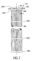
- the particulate- laden gas D is filtered by a plurality of filters 60 (Fig. 2) of the filter mounting system 22 installed in the baghouse 20. Particulates are removed from the gas flow by the filters 60.
- Cleaned gas C then flows from the interior of the filters 60 and exits the baghouse 20 through an outlet 62.
- the baghouse 20 is divided into a "dirty air” plenum 80 and a "clean air” plenum 82 by a tubesheet 84 made from a suitable material, such as a metal plate or sheet.
- the inlet 42 is in fluid communication with the dirty air plenum 80.
- the outlet 62 is in fluid communication with the clean air plenum 82.
- the tubesheet 84 has at least a portion that is substantially planar for mounting and supporting the filters 60.
- a plurality of openings 106 extend through the planar portion of the tubesheet 84.
- Each opening 106 in the tubesheet 84 has an effective diameter D0 (best seen in Fig. 3), defined by the inner circumferential surface of the opening, through which components of the filter mounting system 22 can be installed or moved.
- the housing 40 (Fig. 1) of the baghouse 20 includes sides 120 and a roof 122.
- the baghouse 20 also has an accumulation area 124 defined by sloped walls 126 located at a lower end of the dirty air plenum 80. Particles in the accumulation area 124 can be removed through the bottom region 128 of the baghouse 20.
- the filters 60 are illustrated as extending a distance that approaches the dirty air plenum 80. It will be apparent that the filters 60 may extend into the dirty air plenum 80.
- the filter mounting system 22 includes a resilient mounting gasket 140 (Figs. 1-7) that is located in the opening 106 in the tubesheet 84 (best seen in Figs. 4-7).
- the filter mounting system 22 also includes filters 60 that separate particulates from the particulate-laden gas D as the gas passes radially inward through each filter.
- the illustrated filters 60 are in the form of a "cartridge” but could be in the form of a "bag” or other suitable configuration.
- Each filter 60 is supported at its upper end as viewed in Figs. 1-7, by the tubesheet 84 and gasket 140, and extends downwardly in a substantially vertical direction. It will be apparent that the filters 60 could be oriented in any direction. As illustrated in Fig. 2, each filter 60 is positioned to extend downwardly through the gasket 140, and the opening 106 in tubesheet 84, until a portion of the filter rests against an upper end surface of the gasket.
- the gasket 140 (Fig. 4) has a tubesheet receiving portion 142 and a filter receiving portion 144 extending axially from the tubesheet receiving portion.
- the tubesheet receiving portion 142 of the gasket 140 has a relatively constant maximum outer diameter D1 (Fig. 3) that is greater than the diameter D0 of the opening 106 in the tubesheet 84.
- the filter receiving portion 144 of the gasket 140 has a tapered outer surface with a largest outer diameter D2 that is greater than the diameter D0 of the opening 106.
- the diameter D2 of the filter receiving portion 144 is less than the diameter D1 of the tubesheet receiving portion 142.
- a U-shaped groove 188 is formed in an outer region of the tubesheet receiving portion 142 of the gasket 140.
- the groove 188 has an inner diameter D3 that is substantially equal to the diameter D0 of the opening 106.
- the tubesheet receiving portion 142 has a tapered inner surface 242 with a minimum inner diameter D4 when the gasket 140 is in its "free" or uninstalled state.
- the filter receiving portion 144 has a tapered inner surface 240 with a minimum inner diameter D5 that is less than diameter D4.
- a mounting collar 160 (Figs. 2 and 3) of the filter 60 is adapted to be positioned within the filter receiving portion 144 of the gasket 140 and to engage the filter receiving portion and effect sealing engagement of the tubesheet receiving portion 142 of the gasket against a portion of the tubesheet 84 adjacent the opening 106.
- the filter receiving portion 144 extends axially from the tubesheet receiving portion 142 and forces one portion of the gasket 140 into sealing engagement with a surface of the tubesheet 84 upon engagement with the mounting collar 160.
- the gasket 140 (Figs. 3 and 4) is preferably made from a resilient elastomeric material, such as a terpolymer of ethylene, propylene and a diene (EPDM) that can easily be molded.
- the gasket 140 may also be made from any similar suitable material such as natural rubber, synthetic rubber or silicone rubber.
- the gasket 140 has a hardness in the range of about 30 to 65 Shore A.
- the filter 60 includes filtration media in the form of a pleated filter element 162 (Fig. 6).
- the filter 60 includes a perforated support structure or tube 164.
- the support tube 164 is made of any suitable material such as plastic or metal.
- the pleated filter element 162 is located concentrically around the support tube 164.
- the support tube 164 prevents the pleated filter element 162 from moving in a radial inward direction during operation. It will be apparent that the pleated filter element 162 could alternatively be located radially inward of the tube 164.
- the pleated filter element 162 is formed in a substantially tubular shape about the outer perimeter of the tube 164 with accordion folds at its inner and outer peripheries, as is known.
- the pleated filter element 162 may be constructed of any suitable material for a desired filtering requirement.
- Each filter 60 has a longitudinal central axis A. It will be appreciated that support tube 164, shown as a perforated sleeve, may be substituted with a cage and the pleated filter element 162 may be substituted for a "bag".
- the upper ends of the tube 164 and pleated filter element 162 are located in the mounting collar 160 during molding of the mounting collar to seal and retain the pleated filter element and the support tube.
- the mounting collar 160 is integrally formed with the pleated filter element 162 and support tube 164 during a molding operation to provide a "unitary" cartridge.
- the mounting collar 160 is made from a material that is preferably relatively rigid.
- the mounting collar 160 has a maximum outer diameter D6 (Fig. 3) that is greater than the largest inner diameter D4 of the gasket 140 and diameter D0 of the opening 106 in the tubesheet 84 so the filter 60 cannot move downwardly completely through the gasket and opening.
- the mounting collar 160 is preferably molded from a plastic material. It will be apparent that any suitable rigid material can be used, such as a plastic, epoxy, ceramic, metal, silicone, or urethane composition.
- the molded mounting collar 160 has a hardness in the range of 50 Shore A to 85 Shore D, preferably at least 70 Shore D. In any case, the mounting collar 160 has a hardness greater than the hardness of the gasket 140. This preferred hardness assures that the mounting collar 160 is sufficiently rigid and not prone to significant deformation under typical installation and operational forces. The preferred hardness differential also assures that the gasket 140 deforms rather than the mounting collar 160 during installations and operation. Since the mounting collar 160 is preferably molded it is generally cheaper, easier and faster to fabricate than some previous known filter mounting structure with metal components.
- the filter 60 has a molded lower end cap 180 (Fig. 2).
- the pleated filter element 162 and support tube 164 are molded into the end cap 180 preferably by the same rigid material as the mounting collar 160, such as plastic, epoxy, ceramic, silicone, or urethane composition.
- a pair of retention devices 182 retain the pleated filter element 162 from excessive radial outward movement during a cleaning cycle of back-flushing gas.
- a pair of retention devices 182 are illustrated on the filter 60 for example purposes only. The exact number of retention devices 182 used depends on the length of the pleated filer media element 162.
- annular ridge or surface 202 extends radially outward from the mounting collar 160.
- the annular surface 202 establishes the position of the filter 60 against an upper surface of the gasket 140 and, thus, relative to the tubesheet 84 when the components are properly installed.
- the annular surface 202 also forms part of a seal with the gasket 140.
- the mounting collar 160 has a first or lower tapered outer surface 262 with a diameter D7 and a second or upper tapered outer surface 264 with a diameter D8 greater than the diameter D7.
- a generally cylindrical outer surface 266 with an outer diameter D9 is located axially between the first tapered surface 262 and second tapered surface 264.
- a generally cylindrical end surface 268 with a diameter D10 extends from the lower tapered surface 262.
- the gasket 140 must be installed in the opening 106 of the tubesheet before the filter 60 is moved into the gasket.
- the filter receiving portion 144 functions as a lever to pivot the tubesheet receiving portion 142 into engagement with the portion of the tubesheet 84.
- a projection 220 extends radially inward from the lowered tapered surface 240 of the gasket 140.
- a receiving area in the form of a groove 222 is formed in the mounting collar 160. The projection 220 is receivable within the groove 222 and engageable with a surface defining the groove to locate and secure the mounting collar 160 relative to the gasket 140 and form a seal therebetween and to provide increased resistance to upward movement of the filter 60.
- the gasket 140 may be easily deformed and manually inserted into the opening 106 in the tubesheet 84 prior to receiving the filter 60.
- a bottom surface 244 (Fig. 4) of the groove 188 in the gasket 140 snugly engages the circumferential inner surface defining the opening 106 in the tubesheet 84.
- Side surfaces 246, 248 of the groove 188 may or may not engage surfaces of the tubesheet 84 adjacent the opening 106.
- the groove 188 can be slightly wider than thickness T of the tubesheet 84 adjacent the opening 106.
- the end cap 180 and the majority pleated filter element 162 are moved axially downward through the gasket 140 properly seated in the opening 106.
- the end 268 of the mounting collar 160 is moved axially downward relative to the gasket 140 to concentrically align the filter 60.
- the lower tapered surface 262 of the mounting collar 160 passes through the upper tapered surface 242 of the gasket 140.
- the lower tapered surface 262 of the mounting collar 160 then engages the lower tapered surface 240 of the gasket 140.
- the lowermost part of the filter receiving portion 144 of the gasket moves in a radial outward direction and forces or pivots, the outermost radial portion 280 of the lower surface 248 of groove 188 to engage and seal the gasket 140 against a portion of the lower surface of the tubesheet 84 adjacent opening 106. This occurs around the entire circumference of the opening 106 as the filter 60 moves further axially downward relative to the gasket 140 and tubesheet 84.
- the upper tapered surface 264 of the mounting collar 160 engages the upper tapered surface 242 of the gasket 140.
- This action forces the upper surface 246 of the groove 188 in the tubesheet receiving portion 142 of the gasket 140 to pivot downwardly against upper surface of the tubesheet 84 adjacent the opening 106.
- Annular surface 202 engages the uppermost surface of the gasket 140 and further forces the upper surface 246 of the groove in the tubesheet receiving portion 142 against the tubesheet 84 to form a quality seal.
- any potential leakage path between the tubesheet 84 and gasket 140 as well as between the gasket and mounting collar of the filter 60 is blocked by the filter mounting system of the present invention.
- Friction between the gasket 140 and mounting collar 160 of the filter 60 provides a significant force to retain the filter in a fixed position relative to the gasket as well as the gasket against the tubesheet 84.
- additional structure is provided to assure that the filter 60 does not unintentionally move axially upward relative to the gasket 140 and tubesheet 84 and thereby adversely affect the sealing of the filter mounting system 22 of the present invention.
- Such structure is in the form of the projection 220 on the gasket 140 being received in the circumferential groove 222 in the mounting collar 160 upon the filter 60 being moved a sufficient downward amount relative to the gasket so the projection can snap radially outwardly a relatively small amount into the groove. This interaction creates more resistance to upward movement of the filter 60 relative to the gasket 140 and tubesheet 84.
- the gasket 140 also includes an inner beveled edge 230 at the lower end of the filter receiving portion 144.
- the beveled edge 230 is a region that does not engage the mounting collar 160.
- the lower area of the gasket 140 does not catch the mounting collar 160 upon removal by upward movement of the filter 60 from within the gasket. This minimizes the possibility of the gasket 140 "rolling up” and interfering with removal of the filter 60.
- the filter mounting system 22 of the present invention is highly useful for providing an effective dust-tight seal between a filter 60 and baghouse tubesheet 84.
- the present invention is also easy to manufacture, install, and replace, and may be subjected to loads which will not cause the seal to be broken.
- the present invention also accommodates a greater variation in the diameter of the opening 106 in the tubesheet 84 that the filter mounting system 22 may be installed in.
- An alternate embodiment of the present invention includes a filter mounting system 400 (Fig. 8) with a filter 402 and gasket 404.
- the filter 402 can be of any suitable structure, such as the illustrated "cartridge" structure.
- the filter 402 includes a mounting collar 420.
- the mounting collar 420 is preferably molded from a plastic material. It will be apparent that any suitable rigid material can be used, such as a plastic, epoxy, ceramic, silicone, or urethane composition.
- the molded mounting collar 420 has a hardness in the range of Shore D 30 to Shore D 85 and preferably at least Shore D 70. This relative hardness assures that the mounting collar 420 is substantially rigid and not prone to significant deformation under typical installation and operational forces. Since the mounting collar 420 is molded it is generally cheaper, easier and faster to fabricate than some previous known filter mounting structure components.
- the filter media 402 includes filter media in the form of a pleated filter element 440 (Fig. 10).
- the filter 402 also includes a perforated support structure or tube 442.
- the support tube 442 is made of any suitable material such as plastic or metal.
- the pleated filter element 440 is located concentrically around the support tube 442.
- the support tube 442 prevents the pleated filter element 440 from moving in a radial inward direction during operation. It will be apparent that the pleated filter element 440 could alternatively be located radially inward of the tube 442.
- the pleated filter element 440 is formed in a substantially tubular shape about the outer perimeter of the tube 442 with accordion folds at its inner and outer peripheries.
- the pleated filter element 440 may be constructed of any suitable material for a desired filtering requirement.
- Each filter 402 has a longitudinal central axis AA.
- the mounting collar 420 is integrally formed with the pleated filter element 440 and tube 442 during a molding operation to provide a "unitary" cartridge.
- the tube 442 and pleated filter element 440 are structurally and sealingly secured to the mounting collar 420.
- the mounting collar 420 has an upper portion with a lower annular surface 444 (Fig. 8) with outer diameter D20 that is greater than the inner diameter D21 of the opening 106 in the tubesheet 84.
- the annular surface 444 extends from the mounting collar 420.
- the annular surface 444 establishes the position of the filter 402 against an upper surface of the gasket 404 and, thus, relative to the tubesheet 84.
- the annular surface 444 also forms part of a seal with the gasket 404.
- a relatively strong connection and structure with a good seal exists that is capable of supporting the weight of the filter a 402 as it hangs from the tubesheet 84 even when the filter assembly has a relatively heavy accumulation of particles.
- cylindrical filter 402 is positioned downwardly through gasket 404, and the opening 106 in tubesheet 84, until the annular surface 444 of the mounting collar 420 rests against an upper surface of the gasket as described in detail below.
- the mounting collar 420 includes a lower tubular portion 460 (Fig. 8) with an outer diameter D22.
- the mounting collar 420 has a pair of continuous projections 480, 482 with outer diameters D23 extending radially outward from the tubular portion 460.
- Each of the projections 480, 482 extends continuously about the circumference of the mounting collar 420.
- the projections 480, 482 are longitudinally spaced apart along the axis AA, a distance D that is substantially equal to or slightly greater than the thickness T of the tubesheet 84.
- Each of the projections 480, 482 has an outer diameter D23 which is slightly larger than an inner diameter D24 of the gasket 404.
- Each projection 480, 482 has a frustoconical leading edge surface 484, 486, respectively, to facilitate installation and concentric seating of the mounting collar 420 within the gasket 404.
- the gasket 404 (Fig. 9) has a tubesheet receiving portion 500 and a filter receiving portion 502 extending from the tubesheet receiving portion.
- the mounting collar 420 of the filter 402 is adapted to be positioned within the filter receiving portion 502 of the gasket 404 to engage the filter receiving portion and effect sealing engagement of the tubesheet receiving portion 500 of the gasket against a portion of the tubesheet 84 adjacent the opening 106.
- the filter receiving portion 502 extends axially from the tubesheet receiving portion 500 to force one portion of the gasket 404 into sealing engagement with a surface of the tubesheet 84 upon engagement with the mounting collar 420.
- the gasket 404 has a pair of axially spaced protrusions 520, 522 in the tubesheet receiving portion 500. The protrusions 520, 522 are spared apart by a depression 524 that has an axial length greater than the thickness T of the tubesheet 84.
- the gasket 404 (Figs. 3 and 4) is preferably made from a resilient elastomeric material, such as a terpolymer of ethylene, propylene and a diene (EPDM) that can easily be molded.
- the gasket 404 may also be made from any similar suitable material such as natural rubber, synthetic rubber or silicone rubber.
- Preferably the gasket 404 has a hardness in the range of about 30 to 65 Shore A.
- the mounting collar 420 is positioned within the gasket 404 to engage the inner surface of the gasket and effect sealing engagement of the gasket against a portion of the opening 106 in the tubesheet 84.
- the upper projection 482 extends radially from the mounting collar 420 to force the upper protrusion 520 (Fig. 10) of the gasket 404 to sealingly engage the gasket 404 against a surface of the tubesheet 84 adjacent an upper portion of the opening 106, as illustrated in Fig. 11.
- the lower projection 480 forces the lower protrusion 522 of the gasket 404 into sealing engagement with another surface of the tubesheet 84 adjacent a lower portion of the opening 106.
- the upper projection 482 of the mounting collar 420 is adapted to be located above the midpoint M of the thickness T of the tubesheet 84 to further force the upper protrusion 520 of the gasket 404 cause sealing engagement with the tubesheet 106.
- the lower projection 480 of the mounting collar is adapted to be located below the midpoint M of the thickness T of the tubesheet 84 to further force the lower protrusion 522 of the gasket 404 cause sealing engagement with the tubesheet 84.
- the protrusions 520, 522 are separated by the depression 524 that minimizes friction between the gasket 404 and mounting collar 420 that could cause the gasket to roll up and move from within the opening 106 in the tubesheet 84 during installation of the filter 60.
- the gasket 404 also has a generally U-shaped groove 540 (Fig. 8) found in its outer surface.
- the gasket 404 also has a lower projecting portion 542 (Fig. 9) with an inner diameter D25 located between two tapered surfaces 544, 546 of the filter receiving portion 502.
- the flexible gasket 404 is positioned into the opening 106 in the tubesheet 84 by inwardly flexing and deforming the gasket to collapse it.
- the gasket 404 is positioned within the opening so the groove 540 captures a portion of the tubesheet 84.
- the deforming force is then released to allow the gasket 404 to resiliently engage the inner periphery of the opening 106.
- the filter 402 is inserted into the opening 106 so the pleated filter element 440 extends through the gasket 404.
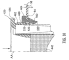
- the mounting collar 420 is then pressed downwardly into the gasket 404 until a lower lead edge 486 of the projection 480 engages the tapered surface 544 of the gasket 404, as illustrated in Fig. 10.
- the filter 402 is forced further into the gasket 404.
- the leading surface 486 of the lower projection 480 of the mounting collar 420 engages the tapered surface 544 of the filter receiving portion 502 of the gasket during downward movement of the filter 60 relative to the tubesheet 84.
- the filter receiving portion 502 pivots so at least a portion of the lower surface of the groove 540 engages the lower surface of the tubesheet 84 adjacent the opening 106. This provides a quality seal between the filter 60 and tubesheet 84.
- the outwardly extending projections 480, 482 of mounting collar 420 are in the position shown in Fig. 11.
- the lower projection 480 engages with the protrusion 522 of gasket 404 at a location that is substantially at, or slightly lower than, the midpoint M of the thickness T of the tubesheet 84.
- the uppermost projection 482 engages the protrusion 520 of the gasket 404 at a location above the midpoint M of the thickness T of the tubesheet 84.
- the projections 480, 482 force the respective protrusions 520, 522 into further continuous sealing engagement with two different surfaces of the tubesheet 84 adjacent the opening 106.
- the tubular portion 460 of the mounting collar 420 engages and seats against the projecting portion 542 to form a seal.
- mounting collar 420 and gasket 404 are such that, when mounting collar is properly positioned within the gasket, the annular surface 444 of the mounting collar rests on the upper surface of the gasket. This is highly desirable because loads applied to the mounting collar 420 of the filter assembly 28, such as when workers are walking thereon, are transmitted downwardly to the gasket 404 and tubesheet 84 and do not adversely effect the seal established by the gasket.
- the lower tapered surface or beveled edge 546 at the lower end of the filter receiving portion 502 of the gasket 404 does not engage the mounting collar 420.
- the lower area of the gasket 404 does not catch the mounting collar 420 upon removal by upward movement of the filter 60 from within the gasket. This minimizes the possibility of the gasket 404 "rolling up” and interfering with removal of the filter 60.
- the present invention is highly useful for providing an effective dust-tight seal between a filter 402 and tubesheet 84.
- the present invention is also easy to manufacture, install, and replace, and may be subjected to loads which will not cause the seal to be broken.
- the filter 402 of the present invention may be walked on after it is installed in a baghouse 20 and not lose its seal. This is attributable to the new rigid non-metallic mounting collar 420 that will not deform during such loads and retains its shape against the gasket 404 that it was installed with.
Landscapes
- Chemical & Material Sciences (AREA)
- Chemical Kinetics & Catalysis (AREA)
- Physics & Mathematics (AREA)
- Geometry (AREA)
- Filtering Of Dispersed Particles In Gases (AREA)
- Control Of Motors That Do Not Use Commutators (AREA)
- Coils Or Transformers For Communication (AREA)
- Piezo-Electric Or Mechanical Vibrators, Or Delay Or Filter Circuits (AREA)
- External Artificial Organs (AREA)
Abstract

Description
- The present invention is generally directed to a filter assembly for use in a dust collector. In particular, the present invention is directed to a filter cartridge structure and apparatus for mounting and supporting the filter cartridge in the dust collector.
- Dust collectors, such as baghouses, for filtering particulate-laden air are well known. A typical baghouse has a housing with a dirty air chamber and a clean air chamber. The two chambers are separated by sheet metal, commonly referred to as a tubesheet. The tubesheet has a number of openings through which cylindrical filters, such as bags or cartridges, typically extend. The filters are suspended by the tubesheet and extend into the dirty air chamber. Particulate-laden air is introduced into the dirty air chamber. The air passes through the filters and through the openings in the tubesheet into the clean air chamber. The particulates are separated from the air flow by the filters. The filtered air is exhausted from the clean air chamber or directed for other uses.
- Important in the design of a filter bag or filter cartridge and associated support structure is that a good seal must exist between the filter and the supporting tubesheet. If a good seal does not exist, particulate-laden air may leak around the filter, through the tubesheet opening and into the clean air chamber. This leakage results in the undesirable situation of having particulate-laden air in the clean air chamber.
- Numerous attempts have been made to develop a baghouse filter and support structure for attaching a filter element to a baghouse tubesheet. U.S. Pat. Nos. 4,292,057; 4,424,070; 4,436,536; 4,443, 237 and 4,445,915 are representative examples of prior art filter elements and attachment structure. U.S. Patent No. 5,632,791 discloses a flexible sleeve molded from relatively soft urethane material that directly engages a surface defining an opening in the tubesheet. U.S. Patent No. 5,746,792 discloses a metal mounting collar that is engagable with a flexible snapband for sealing against a tubesheet.
- In spite of significant efforts at solving the problems and disadvantages with prior art filters, the prior art filters and associated support structure tend to be complex, which adds to the cost of the filter and installation in the baghouse. The prior art filters also have not been altogether satisfactory in preventing particulate-laden air from leaking from the dirty air chamber, through the tubesheet opening, and into the clean air chamber. The mounting and sealing of filters within a baghouse tubesheet remains one of the most time-consuming and expensive operations in the manufacture of baghouses and in the replacement of filters.
- U.S. Patent Application Serial Number 10/448,693 discloses a filter cartridge and support structure for use in a baghouse having a tubesheet with openings. A flexible snapband with a metal spring component and fabric cover is biased into engagement with a surface of the opening in the tubesheet. The snapband receives a portion of the filter cartridge. A rigid non-metallic tubular mounting collar is integrally formed with filter media. The mounting collar includes a pair of longitudinally spaced continuous projections that extend radially outward. The mounting collar is adapted to be positioned within the snapband and engage surfaces of the snapband to effect sealing engagement of the snapband against surfaces of the opening in the tubesheet.
- Yet another known attempt at a baghouse support and seal structure involves the use of a rubber grommet having a substantially C-shaped cross-section. The grommet is installed in a tubesheet opening and receives a metal ferrule. During insertion of the ferrule into the grommet, friction from relative movement therebetween tends to pull or roll the grommet out of position. The out-of-position grommet may not provide an effective seal with the tubesheet and ferrule.
- Prior art filter mounting systems that incorporate metal mounting collars can be expensive to manufacture and take a relatively long time to fabricate. Snapbands are relatively expensive to manufacture, have relatively small tolerance of opening that they can properly fit and variations in cover fabric thickness makes it difficult to produce consistent finished sizes. Accordingly, the need exists for a filter and mounting systems that are inexpensive, can be quickly manufactured, easy to install and replace in a baghouse and that maintain a good seal. The present invention fills these needs and overcomes the disadvantages of the prior art filter mounting systems.
- The present invention is directed to a filter mounting system for use in a baghouse having a tubesheet with a plurality of openings. The filter mounting system according to one embodiment of the present invention comprises a filter assembly including filter media and a tubular mounting collar to mount the filter media relative to the tubesheet. The filter mounting system also comprises a gasket made of a flexible material. The gasket has a tubesheet receiving portion and a filter receiving portion extending from the tubesheet receiving portion. The mounting collar of the filter assembly is adapted to be positioned within the filter receiving portion of the gasket and engage the filter receiving portion to effect sealing engagement of the tubesheet receiving portion of the gasket against a portion of the tubesheet adjacent the opening. The filter receiving portion extends from the tubesheet receiving portion to force one portion of the gasket into sealing engagement with a surface of the tubesheet upon engagement with the mounting collar.
- The filter receiving portion of the gasket has a tapered surface that functions as a lever to pivot the tubesheet receiving portion into engagement with the portion of the tubesheet. The filter assembly is a filter cartridge and the filter media is a pleated filter element. An annular surface extends from the mounting collar for establishing the position of the filter cartridge relative to the tubesheet and for sealing engagement of another portion of the gasket with another surface of the tubesheet.
- A projection extends from one of the mounting collar and the gasket. A groove is formed in the other of the gasket and the mounting collar. The projection is receivable within the groove to locate and secure the mounting collar relative to the gasket and further form a seal therebetween.
- The hardness of the gasket is less than the hardness of the mounting collar. The filter receiving portion of the gasket is made from a conformable material having a hardness in the range of about 30 to 65 Shore A. The mounting collar is made from a rigid non-metallic material having a hardness in the range of about 50 Shore A to 85 Shore D.
- In another embodiment of the invention, the filter mounting system comprises a filter and a gasket. The filter includes filter media and a tubular mounting collar to mount the filter media relative to the tubesheet. The gasket is made of a flexible material. The gasket has a tubesheet receiving portion and a filter receiving portion axially spaced from the tubesheet receiving portion. The tubesheet receiving portion has a pair of axially spaced tubular surfaces. The mounting collar includes a pair of axially spaced continuous circumferential projections extending from the collar. The mounting collar is adapted to be positioned within said tubesheet receiving portion of the gasket. Each projection of the mounting collar engages a respective one of the tubular surfaces of the tubesheet receiving portion to force portions of the gasket against surfaces of the tubesheet adjacent the opening to effect sealing engagement therebetween.
- The mounting collar is also adapted to be positioned within the filter receiving portion of the gasket and engage the filter receiving portion to effect sealing engagement of the tubesheet receiving portion of the gasket against another portion of the tubesheet adjacent the opening. The filter receiving portion extends from the tubesheet receiving portion to force one portion of the gasket into sealing engagement with a surface of the tubesheet upon engagement with the mounting collar. The mounting collar further includes an annular surface extending from the mounting collar for establishing the position of the filter relative to the tubesheet.
- The invention will now be described in greater detail, by way of example, with reference to the drawings, in which:-
- Fig. 1 is a schematic view, partly in section, of a baghouse with a filter mounting system constructed according to the present invention;
- Fig. 2 is an elevational view of the filter mounting systems supporting a filter in an opening of a tubesheet of the baghouse;
- Fig. 3 is an enlarged exploded view, partly in section, of a portion of the filter mounting system according to one embodiment of the present invention, taken approximately along line 3-3 in Fig. 2;
- Fig. 4 is an enlarged sectional view of a portion of a gasket of the filter mounting system of the present invention;
- Fig. 5 is an enlarged sectional view of a portion of the gasket installed in an opening in the tubesheet of the baghouse;
- Fig. 6 is an enlarged sectional view of a filter being installed into the gasket mounted in the opening in the tubesheet;
- Fig. 7 is a view of the filter mounting system similar to Fig. 6 with the filter installed in the gasket and tubesheet:
- Fig. 8 is an enlarged exploded view, partly in section and similar to Fig. 3, of a portion of the filter mounting system according to another embodiment of the present invention;
- Fig. 9 is an enlarged sectional view of a portion of the gasket, illustrated in Fig. 8, installed in an opening in the tubesheet of the baghouse;
- Fig. 10 is an enlarged sectional view of a filter being installed into the gasket mounted in the opening in the tubesheet; and
- Fig. 11 is a view similar to Fig. 10 with the filter installed in the gasket and tubesheet.
-
- A
baghouse 20 incorporating afilter mounting system 22 constructed according to one embodiment of the present invention is illustrated in Fig. 1. Thebaghouse 20 is defined by anenclosed housing 40. Thehousing 40 is made from a suitable material, such as sheet metal. Dirty or particulate-laden gas D enters thebaghouse 20 through aninlet 42. The particulate- laden gas D is filtered by a plurality of filters 60 (Fig. 2) of thefilter mounting system 22 installed in thebaghouse 20. Particulates are removed from the gas flow by thefilters 60. Cleaned gas C then flows from the interior of thefilters 60 and exits thebaghouse 20 through anoutlet 62. - The
baghouse 20 is divided into a "dirty air"plenum 80 and a "clean air"plenum 82 by atubesheet 84 made from a suitable material, such as a metal plate or sheet. Theinlet 42 is in fluid communication with thedirty air plenum 80. Theoutlet 62 is in fluid communication with theclean air plenum 82. Thetubesheet 84 has at least a portion that is substantially planar for mounting and supporting thefilters 60. - A plurality of
openings 106 extend through the planar portion of thetubesheet 84. Eachopening 106 in thetubesheet 84 has an effective diameter D0 (best seen in Fig. 3), defined by the inner circumferential surface of the opening, through which components of thefilter mounting system 22 can be installed or moved. - The housing 40 (Fig. 1) of the
baghouse 20 includessides 120 and aroof 122. Thebaghouse 20 also has anaccumulation area 124 defined by slopedwalls 126 located at a lower end of thedirty air plenum 80. Particles in theaccumulation area 124 can be removed through thebottom region 128 of thebaghouse 20. Thefilters 60 are illustrated as extending a distance that approaches thedirty air plenum 80. It will be apparent that thefilters 60 may extend into thedirty air plenum 80. - The
filter mounting system 22 includes a resilient mounting gasket 140 (Figs. 1-7) that is located in theopening 106 in the tubesheet 84 (best seen in Figs. 4-7). Thefilter mounting system 22 also includesfilters 60 that separate particulates from the particulate-laden gas D as the gas passes radially inward through each filter. The illustrated filters 60 are in the form of a "cartridge" but could be in the form of a "bag" or other suitable configuration. Eachfilter 60 is supported at its upper end as viewed in Figs. 1-7, by the tubesheet 84 andgasket 140, and extends downwardly in a substantially vertical direction. It will be apparent that thefilters 60 could be oriented in any direction. As illustrated in Fig. 2, eachfilter 60 is positioned to extend downwardly through thegasket 140, and theopening 106 intubesheet 84, until a portion of the filter rests against an upper end surface of the gasket. - The gasket 140 (Fig. 4) has a
tubesheet receiving portion 142 and afilter receiving portion 144 extending axially from the tubesheet receiving portion. Thetubesheet receiving portion 142 of thegasket 140 has a relatively constant maximum outer diameter D1 (Fig. 3) that is greater than the diameter D0 of theopening 106 in thetubesheet 84. Thefilter receiving portion 144 of thegasket 140 has a tapered outer surface with a largest outer diameter D2 that is greater than the diameter D0 of theopening 106. The diameter D2 of thefilter receiving portion 144 is less than the diameter D1 of thetubesheet receiving portion 142. - A
U-shaped groove 188 is formed in an outer region of thetubesheet receiving portion 142 of thegasket 140. Thegroove 188 has an inner diameter D3 that is substantially equal to the diameter D0 of theopening 106. Thetubesheet receiving portion 142 has a taperedinner surface 242 with a minimum inner diameter D4 when thegasket 140 is in its "free" or uninstalled state. Thefilter receiving portion 144 has a taperedinner surface 240 with a minimum inner diameter D5 that is less than diameter D4. - A mounting collar 160 (Figs. 2 and 3) of the
filter 60 is adapted to be positioned within thefilter receiving portion 144 of thegasket 140 and to engage the filter receiving portion and effect sealing engagement of thetubesheet receiving portion 142 of the gasket against a portion of thetubesheet 84 adjacent theopening 106. Thefilter receiving portion 144 extends axially from thetubesheet receiving portion 142 and forces one portion of thegasket 140 into sealing engagement with a surface of thetubesheet 84 upon engagement with the mountingcollar 160. The gasket 140 (Figs. 3 and 4) is preferably made from a resilient elastomeric material, such as a terpolymer of ethylene, propylene and a diene (EPDM) that can easily be molded. Thegasket 140 may also be made from any similar suitable material such as natural rubber, synthetic rubber or silicone rubber. - The
gasket 140 has a hardness in the range of about 30 to 65 Shore A. - The
filter 60 includes filtration media in the form of a pleated filter element 162 (Fig. 6). Thefilter 60 includes a perforated support structure ortube 164. Thesupport tube 164 is made of any suitable material such as plastic or metal. Thepleated filter element 162 is located concentrically around thesupport tube 164. Thesupport tube 164 prevents thepleated filter element 162 from moving in a radial inward direction during operation. It will be apparent that thepleated filter element 162 could alternatively be located radially inward of thetube 164. Thepleated filter element 162 is formed in a substantially tubular shape about the outer perimeter of thetube 164 with accordion folds at its inner and outer peripheries, as is known. Thepleated filter element 162 may be constructed of any suitable material for a desired filtering requirement. Eachfilter 60 has a longitudinal central axis A. It will be appreciated thatsupport tube 164, shown as a perforated sleeve, may be substituted with a cage and thepleated filter element 162 may be substituted for a "bag". - The upper ends of the
tube 164 andpleated filter element 162 are located in the mountingcollar 160 during molding of the mounting collar to seal and retain the pleated filter element and the support tube. The mountingcollar 160 is integrally formed with thepleated filter element 162 andsupport tube 164 during a molding operation to provide a "unitary" cartridge. The mountingcollar 160 is made from a material that is preferably relatively rigid. Thus, thesupport tube 164 andpleated filter element 162 are structurally and sealingly secured to the mountingcollar 160. The mountingcollar 160 has a maximum outer diameter D6 (Fig. 3) that is greater than the largest inner diameter D4 of thegasket 140 and diameter D0 of theopening 106 in thetubesheet 84 so thefilter 60 cannot move downwardly completely through the gasket and opening. - The mounting
collar 160 is preferably molded from a plastic material. It will be apparent that any suitable rigid material can be used, such as a plastic, epoxy, ceramic, metal, silicone, or urethane composition. The molded mountingcollar 160 has a hardness in the range of 50 Shore A to 85 Shore D, preferably at least 70 Shore D. In any case, the mountingcollar 160 has a hardness greater than the hardness of thegasket 140. This preferred hardness assures that the mountingcollar 160 is sufficiently rigid and not prone to significant deformation under typical installation and operational forces. The preferred hardness differential also assures that thegasket 140 deforms rather than the mountingcollar 160 during installations and operation. Since the mountingcollar 160 is preferably molded it is generally cheaper, easier and faster to fabricate than some previous known filter mounting structure with metal components. - The
filter 60 has a molded lower end cap 180 (Fig. 2). Thepleated filter element 162 andsupport tube 164 are molded into theend cap 180 preferably by the same rigid material as the mountingcollar 160, such as plastic, epoxy, ceramic, silicone, or urethane composition. A pair ofretention devices 182 retain thepleated filter element 162 from excessive radial outward movement during a cleaning cycle of back-flushing gas. A pair ofretention devices 182 are illustrated on thefilter 60 for example purposes only. The exact number ofretention devices 182 used depends on the length of the pleatedfiler media element 162. - An annular ridge or
surface 202 extends radially outward from the mountingcollar 160. Theannular surface 202 establishes the position of thefilter 60 against an upper surface of thegasket 140 and, thus, relative to thetubesheet 84 when the components are properly installed. Theannular surface 202 also forms part of a seal with thegasket 140. Thus, a relatively strong connection and structure with a good seal exists that is capable of supporting the weight of thefilter 60 as it hangs from thetubesheet 84 even when the filter mounting system is laden with a relatively heavy accumulation of particles. - The mounting
collar 160 has a first or lower taperedouter surface 262 with a diameter D7 and a second or upper taperedouter surface 264 with a diameter D8 greater than the diameter D7. A generally cylindricalouter surface 266 with an outer diameter D9 is located axially between the firsttapered surface 262 and secondtapered surface 264. A generallycylindrical end surface 268 with a diameter D10 extends from the lower taperedsurface 262. - It will be apparent that the
gasket 140 must be installed in theopening 106 of the tubesheet before thefilter 60 is moved into the gasket. During downward movement of thefilter 60 relative to thegasket 140 installed in theopening 106 of thetubesheet 84, thefilter receiving portion 144 functions as a lever to pivot thetubesheet receiving portion 142 into engagement with the portion of thetubesheet 84. Aprojection 220 extends radially inward from the loweredtapered surface 240 of thegasket 140. A receiving area in the form of agroove 222 is formed in the mountingcollar 160. Theprojection 220 is receivable within thegroove 222 and engageable with a surface defining the groove to locate and secure the mountingcollar 160 relative to thegasket 140 and form a seal therebetween and to provide increased resistance to upward movement of thefilter 60. - The
gasket 140 may be easily deformed and manually inserted into theopening 106 in thetubesheet 84 prior to receiving thefilter 60. During installation, a bottom surface 244 (Fig. 4) of thegroove 188 in thegasket 140 snugly engages the circumferential inner surface defining theopening 106 in thetubesheet 84. Side surfaces 246, 248 of thegroove 188 may or may not engage surfaces of thetubesheet 84 adjacent theopening 106. Thegroove 188 can be slightly wider than thickness T of thetubesheet 84 adjacent theopening 106. - To install the
filter 60, theend cap 180 and the majority pleatedfilter element 162 are moved axially downward through thegasket 140 properly seated in theopening 106. Theend 268 of the mountingcollar 160 is moved axially downward relative to thegasket 140 to concentrically align thefilter 60. The lower taperedsurface 262 of the mountingcollar 160 passes through the upper taperedsurface 242 of thegasket 140. The lower taperedsurface 262 of the mountingcollar 160 then engages the lower taperedsurface 240 of thegasket 140. The lowermost part of thefilter receiving portion 144 of the gasket moves in a radial outward direction and forces or pivots, the outermostradial portion 280 of thelower surface 248 ofgroove 188 to engage and seal thegasket 140 against a portion of the lower surface of thetubesheet 84adjacent opening 106. This occurs around the entire circumference of theopening 106 as thefilter 60 moves further axially downward relative to thegasket 140 andtubesheet 84. - Further downward movement of the
filter 60 relative to thegasket 140 and tubesheet 84 from the position illustrated in Fig. 6 to the position illustrated in Fig. 7 results in increased sealing force. Thefilter receiving portion 144 is forced to expand further radially outward a uniform amount about its circumference. This action further forces thelower surface 280 of thegroove 188 of thegasket 140 against the lower surface of thetubesheet 84 adjacent theopening 106. Concurrently, thetubular surface 266 of the mountingcollar 160 engages the inside taperedsurface 240 of thegasket 140 at a location radially inward of thegroove 188. This further forces thebottom surface 244 of thegroove 188 in thegasket 140 against the inner circumferential surface of theopening 106. - Concurrently, the upper tapered
surface 264 of the mountingcollar 160 engages the upper taperedsurface 242 of thegasket 140. This action forces theupper surface 246 of thegroove 188 in thetubesheet receiving portion 142 of thegasket 140 to pivot downwardly against upper surface of thetubesheet 84 adjacent theopening 106.Annular surface 202 engages the uppermost surface of thegasket 140 and further forces theupper surface 246 of the groove in thetubesheet receiving portion 142 against thetubesheet 84 to form a quality seal. Thus, any potential leakage path between the tubesheet 84 andgasket 140 as well as between the gasket and mounting collar of thefilter 60 is blocked by the filter mounting system of the present invention. - Friction between the
gasket 140 and mountingcollar 160 of thefilter 60 provides a significant force to retain the filter in a fixed position relative to the gasket as well as the gasket against thetubesheet 84. However, additional structure is provided to assure that thefilter 60 does not unintentionally move axially upward relative to thegasket 140 and tubesheet 84 and thereby adversely affect the sealing of thefilter mounting system 22 of the present invention. Such structure is in the form of theprojection 220 on thegasket 140 being received in thecircumferential groove 222 in the mountingcollar 160 upon thefilter 60 being moved a sufficient downward amount relative to the gasket so the projection can snap radially outwardly a relatively small amount into the groove. This interaction creates more resistance to upward movement of thefilter 60 relative to thegasket 140 andtubesheet 84. - The
gasket 140 also includes an innerbeveled edge 230 at the lower end of thefilter receiving portion 144. Thebeveled edge 230 is a region that does not engage the mountingcollar 160. Thus, the lower area of thegasket 140 does not catch the mountingcollar 160 upon removal by upward movement of thefilter 60 from within the gasket. This minimizes the possibility of thegasket 140 "rolling up" and interfering with removal of thefilter 60. - The
filter mounting system 22 of the present invention is highly useful for providing an effective dust-tight seal between afilter 60 and baghousetubesheet 84. The present invention is also easy to manufacture, install, and replace, and may be subjected to loads which will not cause the seal to be broken. The present invention also accommodates a greater variation in the diameter of theopening 106 in thetubesheet 84 that thefilter mounting system 22 may be installed in. - An alternate embodiment of the present invention includes a filter mounting system 400 (Fig. 8) with a
filter 402 andgasket 404. Thefilter 402 can be of any suitable structure, such as the illustrated "cartridge" structure. Thefilter 402 includes a mountingcollar 420. The mountingcollar 420 is preferably molded from a plastic material. It will be apparent that any suitable rigid material can be used, such as a plastic, epoxy, ceramic, silicone, or urethane composition. The molded mountingcollar 420 has a hardness in the range of Shore D 30 to Shore D 85 and preferably at least Shore D 70. This relative hardness assures that the mountingcollar 420 is substantially rigid and not prone to significant deformation under typical installation and operational forces. Since the mountingcollar 420 is molded it is generally cheaper, easier and faster to fabricate than some previous known filter mounting structure components. - The
filter media 402 includes filter media in the form of a pleated filter element 440 (Fig. 10). Thefilter 402 also includes a perforated support structure ortube 442. Thesupport tube 442 is made of any suitable material such as plastic or metal. Thepleated filter element 440 is located concentrically around thesupport tube 442. Thesupport tube 442 prevents thepleated filter element 440 from moving in a radial inward direction during operation. It will be apparent that thepleated filter element 440 could alternatively be located radially inward of thetube 442. Thepleated filter element 440 is formed in a substantially tubular shape about the outer perimeter of thetube 442 with accordion folds at its inner and outer peripheries. Thepleated filter element 440 may be constructed of any suitable material for a desired filtering requirement. Eachfilter 402 has a longitudinal central axis AA. - The mounting
collar 420 is integrally formed with thepleated filter element 440 andtube 442 during a molding operation to provide a "unitary" cartridge. Thus, thetube 442 andpleated filter element 440 are structurally and sealingly secured to the mountingcollar 420. The mountingcollar 420 has an upper portion with a lower annular surface 444 (Fig. 8) with outer diameter D20 that is greater than the inner diameter D21 of theopening 106 in thetubesheet 84. - The
annular surface 444 extends from the mountingcollar 420. Theannular surface 444 establishes the position of thefilter 402 against an upper surface of thegasket 404 and, thus, relative to thetubesheet 84. Theannular surface 444 also forms part of a seal with thegasket 404. Thus, a relatively strong connection and structure with a good seal exists that is capable of supporting the weight of the filter a 402 as it hangs from thetubesheet 84 even when the filter assembly has a relatively heavy accumulation of particles. As shown in Fig. 10,cylindrical filter 402 is positioned downwardly throughgasket 404, and theopening 106 intubesheet 84, until theannular surface 444 of the mountingcollar 420 rests against an upper surface of the gasket as described in detail below. - The mounting
collar 420 includes a lower tubular portion 460 (Fig. 8) with an outer diameter D22. The mountingcollar 420 has a pair ofcontinuous projections tubular portion 460. Each of theprojections collar 420. Theprojections tubesheet 84. Each of theprojections gasket 404. Eachprojection leading edge surface collar 420 within thegasket 404. - The gasket 404 (Fig. 9) has a
tubesheet receiving portion 500 and afilter receiving portion 502 extending from the tubesheet receiving portion. The mountingcollar 420 of thefilter 402 is adapted to be positioned within thefilter receiving portion 502 of thegasket 404 to engage the filter receiving portion and effect sealing engagement of thetubesheet receiving portion 500 of the gasket against a portion of thetubesheet 84 adjacent theopening 106. Thefilter receiving portion 502 extends axially from thetubesheet receiving portion 500 to force one portion of thegasket 404 into sealing engagement with a surface of thetubesheet 84 upon engagement with the mountingcollar 420. Thegasket 404 has a pair of axially spacedprotrusions tubesheet receiving portion 500. Theprotrusions depression 524 that has an axial length greater than the thickness T of thetubesheet 84. - The gasket 404 (Figs. 3 and 4) is preferably made from a resilient elastomeric material, such as a terpolymer of ethylene, propylene and a diene (EPDM) that can easily be molded. The
gasket 404 may also be made from any similar suitable material such as natural rubber, synthetic rubber or silicone rubber. Preferably thegasket 404 has a hardness in the range of about 30 to 65 Shore A. - The mounting
collar 420 is positioned within thegasket 404 to engage the inner surface of the gasket and effect sealing engagement of the gasket against a portion of theopening 106 in thetubesheet 84. Theupper projection 482 extends radially from the mountingcollar 420 to force the upper protrusion 520 (Fig. 10) of thegasket 404 to sealingly engage thegasket 404 against a surface of thetubesheet 84 adjacent an upper portion of theopening 106, as illustrated in Fig. 11. Thelower projection 480 forces thelower protrusion 522 of thegasket 404 into sealing engagement with another surface of thetubesheet 84 adjacent a lower portion of theopening 106. - The
upper projection 482 of the mountingcollar 420 is adapted to be located above the midpoint M of the thickness T of thetubesheet 84 to further force theupper protrusion 520 of thegasket 404 cause sealing engagement with thetubesheet 106. Thelower projection 480 of the mounting collar is adapted to be located below the midpoint M of the thickness T of thetubesheet 84 to further force thelower protrusion 522 of thegasket 404 cause sealing engagement with thetubesheet 84. Theprotrusions depression 524 that minimizes friction between thegasket 404 and mountingcollar 420 that could cause the gasket to roll up and move from within theopening 106 in thetubesheet 84 during installation of thefilter 60. - The
gasket 404 also has a generally U-shaped groove 540 (Fig. 8) found in its outer surface. Thegasket 404 also has a lower projecting portion 542 (Fig. 9) with an inner diameter D25 located between twotapered surfaces filter receiving portion 502. - During an installation procedure, the
flexible gasket 404 is positioned into theopening 106 in thetubesheet 84 by inwardly flexing and deforming the gasket to collapse it. Thegasket 404 is positioned within the opening so thegroove 540 captures a portion of thetubesheet 84. The deforming force is then released to allow thegasket 404 to resiliently engage the inner periphery of theopening 106. Thefilter 402 is inserted into theopening 106 so thepleated filter element 440 extends through thegasket 404. The mountingcollar 420 is then pressed downwardly into thegasket 404 until alower lead edge 486 of theprojection 480 engages the taperedsurface 544 of thegasket 404, as illustrated in Fig. 10. Thefilter 402 is forced further into thegasket 404. - The leading
surface 486 of thelower projection 480 of the mountingcollar 420 engages the taperedsurface 544 of thefilter receiving portion 502 of the gasket during downward movement of thefilter 60 relative to thetubesheet 84. Thefilter receiving portion 502 pivots so at least a portion of the lower surface of thegroove 540 engages the lower surface of thetubesheet 84 adjacent theopening 106. This provides a quality seal between thefilter 60 andtubesheet 84. The outwardly extendingprojections collar 420 are in the position shown in Fig. 11. Preferably, thelower projection 480 engages with theprotrusion 522 ofgasket 404 at a location that is substantially at, or slightly lower than, the midpoint M of the thickness T of thetubesheet 84. Theuppermost projection 482 engages theprotrusion 520 of thegasket 404 at a location above the midpoint M of the thickness T of thetubesheet 84. Theprojections respective protrusions tubesheet 84 adjacent theopening 106. Thetubular portion 460 of the mountingcollar 420 engages and seats against the projectingportion 542 to form a seal. - As shown in Fig. 11, the dimensions of mounting
collar 420 andgasket 404 are such that, when mounting collar is properly positioned within the gasket, theannular surface 444 of the mounting collar rests on the upper surface of the gasket. This is highly desirable because loads applied to the mountingcollar 420 of the filter assembly 28, such as when workers are walking thereon, are transmitted downwardly to thegasket 404 and tubesheet 84 and do not adversely effect the seal established by the gasket. - The lower tapered surface or
beveled edge 546 at the lower end of thefilter receiving portion 502 of thegasket 404 does not engage the mountingcollar 420. Thus, the lower area of thegasket 404 does not catch the mountingcollar 420 upon removal by upward movement of thefilter 60 from within the gasket. This minimizes the possibility of thegasket 404 "rolling up" and interfering with removal of thefilter 60. - The present invention is highly useful for providing an effective dust-tight seal between a
filter 402 andtubesheet 84. The present invention is also easy to manufacture, install, and replace, and may be subjected to loads which will not cause the seal to be broken. Thefilter 402 of the present invention may be walked on after it is installed in abaghouse 20 and not lose its seal. This is attributable to the new rigidnon-metallic mounting collar 420 that will not deform during such loads and retains its shape against thegasket 404 that it was installed with.
Claims (10)
- A filter cartridge mounting system (22) for use in a baghouse (20) having a tubesheet (84) with a plurality of openings (106), said filter cartridge mounting system comprising:a filter cartridge (60) including:pleated filter media (162);structure for supporting said filter media (164);a rigid non-metallic tubular mounting collar (160) integrally formed with said filter media (162) and said supporting structure (164) to secure said filter media and said supporting structure to said mounting collar; anda gasket (140) made of a flexible material, said gasket having a tubesheet receiving portion (142) and a filter receiving portion (144) axially spaced from said tubesheet receiving portion;said mounting collar (160) adapted to be positioned within said gasket (140) and engage said filter receiving portion (144) to effect sealing engagement of said tubesheet receiving portion (142) of said gasket against a portion of the tubesheet (84) adjacent the opening (106), said filter receiving portion extending from said tubesheet receiving portion to force one portion of said gasket into sealing engagement with a portion of the tubesheet upon engagement with said mounting collar: andsaid filter receiving portion (144) is tapered to function as a lever to pivot said tubesheet receiving portion (142) so a first sealing portion (248) of said tubesheet receiving portion engages the portion of the tubesheet (84).
- The filter cartridge mounting system (22) of claim 1 wherein a second sealing portion (246) of said tubesheet receiving portion (142) is adapted to be located on a side of the tubesheet (84) opposite said filter receiving portion (144) and a first sealing portion (248) to effect sealing engagement with another portion of the tubesheet (84) adjacent the opening (106) in the tubesheet.
- The filter mounting system (22) of claim 1 further including an annular surface (202) extending from said mounting collar (160) for establishing the position of said filter cartridge (60) relative to the tubesheet (84) and sealing engagement of another portion (246) of said gasket (140) with another portion of the tubesheet.
- The filter mounting system (22) of claim 1 further including an annular surface (202) extending from said mounting collar (160) for establishing sealing engagement with said filter receiving portion (144) of said gasket (140).
- The filter mounting system (22) of claim 1 wherein the hardness of said gasket (140) is less than the hardness of said mounting collar (160).
- The filter mounting system (22) of claim 5 wherein said filter receiving portion (144) of said gasket (140) is made from a conformable material having a hardness in the range of about 30 to 65 Shore A.
- The filter mounting system (22) of claim 5 wherein said mounting collar (160) is made from a rigid non-metallic material having a hardness in the range of about 50 Shore A to 85 Shore D.
- The filter mounting system (22) of claim 1 further including a projection (220) extending from one of said mounting collar (160) and said gasket (140) and a receiving area (222) formed in the other of said gasket and said mounting collar, said projection receivable within the receiving area and engageable with a surface defining the receiving area to locate and secure said mounting collar relative to said gasket and form a seal therebetween.
- The filter mounting system (22) of claim 1 wherein said gasket (140) further includes a first filter receiving portion (240) having a first inner dimension (D5) and a second filter receiving portion (242) having a second inner dimension, the first inner dimension (D4) being less than the second inner dimension.
- The filter mounting system (22) of claim 1 wherein said gasket (140) includes a pair of axially spaced tubular surfaces (524, 542) and said mounting collar (160) includes a pair of axially spaced continuous circumferential projections (480, 482), said mounting collar adapted to be positioned within said gasket and said projections engaging a respective one of said tubular surfaces to force portions of said gasket against two surfaces of the tubesheet (84) adjacent the opening (106) to effect sealing engagement therebetween.
Applications Claiming Priority (2)
| Application Number | Priority Date | Filing Date | Title |
|---|---|---|---|
| US778487 | 1997-01-03 | ||
| US10/778,487 US7186284B2 (en) | 2004-02-13 | 2004-02-13 | Filter mounting system |
Publications (2)
| Publication Number | Publication Date |
|---|---|
| EP1563890A1 true EP1563890A1 (en) | 2005-08-17 |
| EP1563890B1 EP1563890B1 (en) | 2012-01-25 |
Family
ID=34701397
Family Applications (1)
| Application Number | Title | Priority Date | Filing Date |
|---|---|---|---|
| EP05250530A Not-in-force EP1563890B1 (en) | 2004-02-13 | 2005-02-01 | System for mounting filters in a tubesheet |
Country Status (6)
| Country | Link |
|---|---|
| US (1) | US7186284B2 (en) |
| EP (1) | EP1563890B1 (en) |
| CN (1) | CN1676194B (en) |
| AT (1) | ATE542590T1 (en) |
| CA (1) | CA2496217C (en) |
| DK (1) | DK1563890T3 (en) |
Cited By (2)
| Publication number | Priority date | Publication date | Assignee | Title |
|---|---|---|---|---|
| WO2008113353A1 (en) * | 2007-03-19 | 2008-09-25 | Nordic Air Filtration A/S | A filter cartridge comprising a pleated filter element |
| EP2239035A1 (en) * | 2009-04-07 | 2010-10-13 | General Electric Company | Snapband filter for horizontal bottom access collector |
Families Citing this family (22)
| Publication number | Priority date | Publication date | Assignee | Title |
|---|---|---|---|---|
| US7294163B1 (en) * | 2005-03-21 | 2007-11-13 | Lacroix Paul E | Cartridge filter |
| DE102005043791A1 (en) * | 2005-09-13 | 2007-03-15 | Mann + Hummel Gmbh | Device for cleaning air |
| US7632325B2 (en) * | 2006-11-28 | 2009-12-15 | General Electric Company | Filter assembly |
| GB0716659D0 (en) * | 2007-08-25 | 2007-10-03 | Madison Filter 981 Ltd | Filter element constructions |
| US20090114095A1 (en) * | 2007-11-06 | 2009-05-07 | General Electric Company | Filter cleaning system and method |
| CN101780359B (en) * | 2009-11-23 | 2012-01-25 | 安吉县盛丰玻璃纤维有限公司 | Sealing ring of filter bag opening of dust remover and manufacturing method thereof |
| US8580006B2 (en) * | 2010-12-22 | 2013-11-12 | Barry LaCroix | Filter lock and seal system |
| US8580004B1 (en) | 2011-01-21 | 2013-11-12 | iFil USA, LLC | Unitary filter cartridge with flow transition mouth |
| US20120324845A1 (en) * | 2011-06-27 | 2012-12-27 | James Roy Doehla | Filter assembly for use in a baghouse |
| US20120324844A1 (en) * | 2011-06-27 | 2012-12-27 | Tian Xuan Zhang | Filter assembly for use in a baghouse |
| CA2862359C (en) | 2012-01-05 | 2016-12-20 | Tdc Filter Manufacturing, Inc. | Waterproof and salt repellant media and filter |
| USD698017S1 (en) | 2012-07-25 | 2014-01-21 | Tdc Filter Manufacturing, Inc. | Filter adaptor |
| US9616371B1 (en) | 2014-05-06 | 2017-04-11 | iFil USA, LLC | Cartridge filter with flow transition insert |
| US11344833B2 (en) * | 2015-10-05 | 2022-05-31 | Parker-Hannifin Corporation | Filter securing mechanism and attachment method |
| US20170122170A1 (en) * | 2015-10-30 | 2017-05-04 | Caterpillar Inc. | Filter System and Filtration Method for Fluid Reservoirs |
| WO2018009480A1 (en) * | 2016-07-07 | 2018-01-11 | Bha Altair, Llc | Variable diameter top for a filter element |
| US11260335B2 (en) * | 2018-09-18 | 2022-03-01 | Schenck Process Llc | Gaskets and diaphragms for filtration systems |
| US10625194B1 (en) | 2018-12-28 | 2020-04-21 | Schenck Process Llc | Filter cartridges with tubular filter members |
| JP7222740B2 (en) * | 2019-02-06 | 2023-02-15 | 日本スピンドル製造株式会社 | Dust collector filter replacement method and filter |
| DE102019121373B4 (en) * | 2019-08-07 | 2022-03-10 | Netzsch Trockenmahltechnik Gmbh | SEPARATORS WITH PARTIAL FILTRATION |
| DE102019127739A1 (en) | 2019-10-15 | 2021-04-15 | Herding Gmbh Filtertechnik | Filter element, filter element holder for a filter element, a filter device, and a method for manufacturing a filter element |
| CN112742066B (en) * | 2020-12-15 | 2022-09-16 | 青岛麦创智安科技有限公司 | Mesoporous adsorption system applied to large-scale integrated circuit packaging filler processing |
Citations (11)
| Publication number | Priority date | Publication date | Assignee | Title |
|---|---|---|---|---|
| US4292057A (en) | 1975-09-29 | 1981-09-29 | Flex Kleen Corp. | Top removal support for dust collector bags |
| US4424070A (en) | 1982-11-22 | 1984-01-03 | Flex-Kleen Corporation | Dust collecting filter cartridge and attachment structure for suspending same from baghouse tube sheet |
| US4436536A (en) | 1982-09-29 | 1984-03-13 | Flex-Kleen Corporation | Dust collecting filter cartridge and attachment structure for suspending same from baghouse tube sheet |
| US4443237A (en) | 1982-11-22 | 1984-04-17 | Flex-Kleen Corporation | Dust collecting filter cartridge and attachment structure for suspending same from baghouse tube sheet |
| US4445915A (en) | 1982-08-16 | 1984-05-01 | Flex-Kleen Corporation | Dust collector filter cartridge and attachment means for suspending same from baghouse tube sheet |
| US5061303A (en) * | 1989-07-31 | 1991-10-29 | Pneumafil Corporation | Snap-in filter unit |
| US5290441A (en) * | 1991-08-26 | 1994-03-01 | Hosokawa Micron International Inc. | Integrated collar, filter bag, cage and locking ring assembly for baghouses |
| US5632791A (en) | 1994-12-06 | 1997-05-27 | Bha Group, Inc. | Unitary filter cartridge |
| US5746792A (en) | 1996-10-25 | 1998-05-05 | Bha Group Holdings, Inc. | Dust collector filter element and supporting structure |
| US6299662B1 (en) * | 1997-08-21 | 2001-10-09 | Nordic Air Filtration A/S | Filter cartridge |
| EP1273333A1 (en) | 2001-07-06 | 2003-01-08 | WAM S.p.A. | Air filter element |
Family Cites Families (17)
| Publication number | Priority date | Publication date | Assignee | Title |
|---|---|---|---|---|
| US2308310A (en) * | 1942-05-07 | 1943-01-12 | Richard Ruemelin | Filter bag attaching means for dust arresting apparatus |
| US4042356A (en) * | 1976-03-03 | 1977-08-16 | Industrial Clean Air, Inc. | Bag house cell plate and filter bag attachment thereto |
| DK141433B (en) * | 1977-10-24 | 1980-03-17 | Nordisk Pladeroersfabrik As | Holder for filter bag. |
| US4272263A (en) * | 1979-05-21 | 1981-06-09 | American Air Filter Company, Inc. | Filter arrangement |
| US4266954A (en) * | 1979-07-12 | 1981-05-12 | The Air Preheater Company, Inc. | Holder for bag filter |
| DE3006823C2 (en) * | 1980-02-23 | 1982-12-16 | Adolf Dipl.-Ing. 3060 Stadthagen Margraf | Sealing of the opening edge of filter bags on the clean gas side of a dust gas filter |
| US4306893A (en) * | 1980-10-28 | 1981-12-22 | The Air Preheater Company, Inc. | Snap-in assembly for bag filter |
| US4344718A (en) * | 1981-11-02 | 1982-08-17 | Atlantic Richfield Company | Cold weather coupling device |
| GB9405650D0 (en) * | 1994-03-22 | 1994-05-11 | Scape Group Plc | Filtering apparatus |
| US6726735B1 (en) * | 1994-05-06 | 2004-04-27 | Bha Group Holdings, Inc. | Unitary filter cartridge |
| US5730766A (en) * | 1996-11-05 | 1998-03-24 | Bha Group, Inc. | Non-round unitary filter cartridge |
| US5964909A (en) * | 1998-09-04 | 1999-10-12 | Brunner; David | Filter cartridge sealing method |
| DE19845145A1 (en) * | 1998-10-01 | 2000-04-06 | Hydac Process Technology Gmbh | Process for making a seal |
| DE19935297A1 (en) * | 1999-07-27 | 2001-02-01 | Mahle Filtersysteme Gmbh | Filter body of a fluid filter, especially an air filter |
| CN1264465C (en) * | 2001-12-18 | 2006-07-19 | 乐金电子(天津)电器有限公司 | Dust filter of vacuum cleaner |
| US6858052B2 (en) * | 2003-05-30 | 2005-02-22 | Bha Group, Inc. | Filter cartridge mounting structure |
| US6966444B2 (en) * | 2003-09-17 | 2005-11-22 | Morgan Howard W | Filter with snap-fit filter bag |
-
2004
- 2004-02-13 US US10/778,487 patent/US7186284B2/en active Active
-
2005
- 2005-02-01 AT AT05250530T patent/ATE542590T1/en active
- 2005-02-01 DK DK05250530.2T patent/DK1563890T3/en active
- 2005-02-01 EP EP05250530A patent/EP1563890B1/en not_active Not-in-force
- 2005-02-03 CA CA2496217A patent/CA2496217C/en not_active Expired - Fee Related
- 2005-02-08 CN CN200510051631.7A patent/CN1676194B/en not_active Expired - Fee Related
Patent Citations (11)
| Publication number | Priority date | Publication date | Assignee | Title |
|---|---|---|---|---|
| US4292057A (en) | 1975-09-29 | 1981-09-29 | Flex Kleen Corp. | Top removal support for dust collector bags |
| US4445915A (en) | 1982-08-16 | 1984-05-01 | Flex-Kleen Corporation | Dust collector filter cartridge and attachment means for suspending same from baghouse tube sheet |
| US4436536A (en) | 1982-09-29 | 1984-03-13 | Flex-Kleen Corporation | Dust collecting filter cartridge and attachment structure for suspending same from baghouse tube sheet |
| US4424070A (en) | 1982-11-22 | 1984-01-03 | Flex-Kleen Corporation | Dust collecting filter cartridge and attachment structure for suspending same from baghouse tube sheet |
| US4443237A (en) | 1982-11-22 | 1984-04-17 | Flex-Kleen Corporation | Dust collecting filter cartridge and attachment structure for suspending same from baghouse tube sheet |
| US5061303A (en) * | 1989-07-31 | 1991-10-29 | Pneumafil Corporation | Snap-in filter unit |
| US5290441A (en) * | 1991-08-26 | 1994-03-01 | Hosokawa Micron International Inc. | Integrated collar, filter bag, cage and locking ring assembly for baghouses |
| US5632791A (en) | 1994-12-06 | 1997-05-27 | Bha Group, Inc. | Unitary filter cartridge |
| US5746792A (en) | 1996-10-25 | 1998-05-05 | Bha Group Holdings, Inc. | Dust collector filter element and supporting structure |
| US6299662B1 (en) * | 1997-08-21 | 2001-10-09 | Nordic Air Filtration A/S | Filter cartridge |
| EP1273333A1 (en) | 2001-07-06 | 2003-01-08 | WAM S.p.A. | Air filter element |
Cited By (3)
| Publication number | Priority date | Publication date | Assignee | Title |
|---|---|---|---|---|
| WO2008113353A1 (en) * | 2007-03-19 | 2008-09-25 | Nordic Air Filtration A/S | A filter cartridge comprising a pleated filter element |
| EP2239035A1 (en) * | 2009-04-07 | 2010-10-13 | General Electric Company | Snapband filter for horizontal bottom access collector |
| US8167969B2 (en) | 2009-04-07 | 2012-05-01 | General Electric Company | Snapband filter design for horizontal bottom access collector |
Also Published As
| Publication number | Publication date |
|---|---|
| CN1676194B (en) | 2010-12-08 |
| US20050178097A1 (en) | 2005-08-18 |
| CA2496217A1 (en) | 2005-08-13 |
| EP1563890B1 (en) | 2012-01-25 |
| CN1676194A (en) | 2005-10-05 |
| DK1563890T3 (en) | 2012-04-02 |
| ATE542590T1 (en) | 2012-02-15 |
| CA2496217C (en) | 2014-07-22 |
| US7186284B2 (en) | 2007-03-06 |
Similar Documents
| Publication | Publication Date | Title |
|---|---|---|
| CA2496217C (en) | Filter mounting system | |
| US6858052B2 (en) | Filter cartridge mounting structure | |
| US5632791A (en) | Unitary filter cartridge | |
| US7905935B2 (en) | Twist and lock connection for pleated filter element | |
| US7632325B2 (en) | Filter assembly | |
| US5916435A (en) | Conical coreless filter assembly and element | |
| US6726735B1 (en) | Unitary filter cartridge | |
| AU692514B2 (en) | Cylindrical air filter with radially directed seal and method of manufacturing a housing for same | |
| US5730766A (en) | Non-round unitary filter cartridge | |
| US4443237A (en) | Dust collecting filter cartridge and attachment structure for suspending same from baghouse tube sheet | |
| EP2181750B1 (en) | Twist And Lock Connection For Pleated Filter Element With Flange-To-Flange Locking Means | |
| US5061303A (en) | Snap-in filter unit | |
| US7294163B1 (en) | Cartridge filter | |
| AU2007207440B2 (en) | Method and apparatus for reinforcing a sealing collar | |
| US4424070A (en) | Dust collecting filter cartridge and attachment structure for suspending same from baghouse tube sheet | |
| WO2001095992A1 (en) | Baghouse, long filter assembly and method of installation | |
| USRE37163E1 (en) | Unitary filter cartridge | |
| US9776118B2 (en) | Filter element and housing with cooperating filter media support structures | |
| US6179888B1 (en) | Hybrid filter bag assembly | |
| CN109475803B (en) | Variable diameter top for filter element |
Legal Events
| Date | Code | Title | Description |
|---|---|---|---|
| PUAI | Public reference made under article 153(3) epc to a published international application that has entered the european phase |
Free format text: ORIGINAL CODE: 0009012 |
|
| AK | Designated contracting states |
Kind code of ref document: A1 Designated state(s): AT BE BG CH CY CZ DE DK EE ES FI FR GB GR HU IE IS IT LI LT LU MC NL PL PT RO SE SI SK TR |
|
| AX | Request for extension of the european patent |
Extension state: AL BA HR LV MK YU |
|
| 17P | Request for examination filed |
Effective date: 20060217 |
|
| AKX | Designation fees paid |
Designated state(s): AT BE BG CH CY CZ DE DK EE ES FI FR GB GR HU IE IS IT LI LT LU MC NL PL PT RO SE SI SK TR |
|
| 17Q | First examination report despatched |
Effective date: 20080123 |
|
| GRAP | Despatch of communication of intention to grant a patent |
Free format text: ORIGINAL CODE: EPIDOSNIGR1 |
|
| GRAS | Grant fee paid |
Free format text: ORIGINAL CODE: EPIDOSNIGR3 |
|
| GRAA | (expected) grant |
Free format text: ORIGINAL CODE: 0009210 |
|
| AK | Designated contracting states |
Kind code of ref document: B1 Designated state(s): AT BE BG CH CY CZ DE DK EE ES FI FR GB GR HU IE IS IT LI LT LU MC NL PL PT RO SE SI SK TR |
|
| REG | Reference to a national code |
Ref country code: GB Ref legal event code: FG4D |
|
| REG | Reference to a national code |
Ref country code: CH Ref legal event code: EP |
|
| REG | Reference to a national code |
Ref country code: AT Ref legal event code: REF Ref document number: 542590 Country of ref document: AT Kind code of ref document: T Effective date: 20120215 |
|
| REG | Reference to a national code |
Ref country code: IE Ref legal event code: FG4D |
|
| REG | Reference to a national code |
Ref country code: CH Ref legal event code: NV Representative=s name: SERVOPATENT GMBH |
|
| REG | Reference to a national code |
Ref country code: DE Ref legal event code: R096 Ref document number: 602005032363 Country of ref document: DE Effective date: 20120322 |
|
| REG | Reference to a national code |
Ref country code: DK Ref legal event code: T3 |
|
| REG | Reference to a national code |
Ref country code: NL Ref legal event code: VDEP Effective date: 20120125 |
|
| LTIE | Lt: invalidation of european patent or patent extension |
Effective date: 20120125 |
|
| PG25 | Lapsed in a contracting state [announced via postgrant information from national office to epo] |
Ref country code: LT Free format text: LAPSE BECAUSE OF FAILURE TO SUBMIT A TRANSLATION OF THE DESCRIPTION OR TO PAY THE FEE WITHIN THE PRESCRIBED TIME-LIMIT Effective date: 20120125 Ref country code: BE Free format text: LAPSE BECAUSE OF FAILURE TO SUBMIT A TRANSLATION OF THE DESCRIPTION OR TO PAY THE FEE WITHIN THE PRESCRIBED TIME-LIMIT Effective date: 20120125 Ref country code: BG Free format text: LAPSE BECAUSE OF FAILURE TO SUBMIT A TRANSLATION OF THE DESCRIPTION OR TO PAY THE FEE WITHIN THE PRESCRIBED TIME-LIMIT Effective date: 20120425 Ref country code: NL Free format text: LAPSE BECAUSE OF FAILURE TO SUBMIT A TRANSLATION OF THE DESCRIPTION OR TO PAY THE FEE WITHIN THE PRESCRIBED TIME-LIMIT Effective date: 20120125 Ref country code: IS Free format text: LAPSE BECAUSE OF FAILURE TO SUBMIT A TRANSLATION OF THE DESCRIPTION OR TO PAY THE FEE WITHIN THE PRESCRIBED TIME-LIMIT Effective date: 20120525 |
|
| PG25 | Lapsed in a contracting state [announced via postgrant information from national office to epo] |
Ref country code: FI Free format text: LAPSE BECAUSE OF FAILURE TO SUBMIT A TRANSLATION OF THE DESCRIPTION OR TO PAY THE FEE WITHIN THE PRESCRIBED TIME-LIMIT Effective date: 20120125 Ref country code: PT Free format text: LAPSE BECAUSE OF FAILURE TO SUBMIT A TRANSLATION OF THE DESCRIPTION OR TO PAY THE FEE WITHIN THE PRESCRIBED TIME-LIMIT Effective date: 20120525 Ref country code: PL Free format text: LAPSE BECAUSE OF FAILURE TO SUBMIT A TRANSLATION OF THE DESCRIPTION OR TO PAY THE FEE WITHIN THE PRESCRIBED TIME-LIMIT Effective date: 20120125 Ref country code: GR Free format text: LAPSE BECAUSE OF FAILURE TO SUBMIT A TRANSLATION OF THE DESCRIPTION OR TO PAY THE FEE WITHIN THE PRESCRIBED TIME-LIMIT Effective date: 20120426 |
|
| REG | Reference to a national code |
Ref country code: AT Ref legal event code: MK05 Ref document number: 542590 Country of ref document: AT Kind code of ref document: T Effective date: 20120125 |
|
| PG25 | Lapsed in a contracting state [announced via postgrant information from national office to epo] |
Ref country code: CY Free format text: LAPSE BECAUSE OF FAILURE TO SUBMIT A TRANSLATION OF THE DESCRIPTION OR TO PAY THE FEE WITHIN THE PRESCRIBED TIME-LIMIT Effective date: 20120125 Ref country code: MC Free format text: LAPSE BECAUSE OF NON-PAYMENT OF DUE FEES Effective date: 20120229 |
|
| PG25 | Lapsed in a contracting state [announced via postgrant information from national office to epo] |
Ref country code: SE Free format text: LAPSE BECAUSE OF FAILURE TO SUBMIT A TRANSLATION OF THE DESCRIPTION OR TO PAY THE FEE WITHIN THE PRESCRIBED TIME-LIMIT Effective date: 20120125 Ref country code: RO Free format text: LAPSE BECAUSE OF FAILURE TO SUBMIT A TRANSLATION OF THE DESCRIPTION OR TO PAY THE FEE WITHIN THE PRESCRIBED TIME-LIMIT Effective date: 20120125 Ref country code: SI Free format text: LAPSE BECAUSE OF FAILURE TO SUBMIT A TRANSLATION OF THE DESCRIPTION OR TO PAY THE FEE WITHIN THE PRESCRIBED TIME-LIMIT Effective date: 20120125 Ref country code: EE Free format text: LAPSE BECAUSE OF FAILURE TO SUBMIT A TRANSLATION OF THE DESCRIPTION OR TO PAY THE FEE WITHIN THE PRESCRIBED TIME-LIMIT Effective date: 20120125 Ref country code: CZ Free format text: LAPSE BECAUSE OF FAILURE TO SUBMIT A TRANSLATION OF THE DESCRIPTION OR TO PAY THE FEE WITHIN THE PRESCRIBED TIME-LIMIT Effective date: 20120125 |
|
| REG | Reference to a national code |
Ref country code: IE Ref legal event code: MM4A |
|
| PG25 | Lapsed in a contracting state [announced via postgrant information from national office to epo] |
Ref country code: IT Free format text: LAPSE BECAUSE OF FAILURE TO SUBMIT A TRANSLATION OF THE DESCRIPTION OR TO PAY THE FEE WITHIN THE PRESCRIBED TIME-LIMIT Effective date: 20120125 Ref country code: SK Free format text: LAPSE BECAUSE OF FAILURE TO SUBMIT A TRANSLATION OF THE DESCRIPTION OR TO PAY THE FEE WITHIN THE PRESCRIBED TIME-LIMIT Effective date: 20120125 |
|
| PLBE | No opposition filed within time limit |
Free format text: ORIGINAL CODE: 0009261 |
|
| STAA | Information on the status of an ep patent application or granted ep patent |
Free format text: STATUS: NO OPPOSITION FILED WITHIN TIME LIMIT |
|
| 26N | No opposition filed |
Effective date: 20121026 |
|
| PG25 | Lapsed in a contracting state [announced via postgrant information from national office to epo] |
Ref country code: IE Free format text: LAPSE BECAUSE OF NON-PAYMENT OF DUE FEES Effective date: 20120201 Ref country code: AT Free format text: LAPSE BECAUSE OF FAILURE TO SUBMIT A TRANSLATION OF THE DESCRIPTION OR TO PAY THE FEE WITHIN THE PRESCRIBED TIME-LIMIT Effective date: 20120125 |
|
| REG | Reference to a national code |
Ref country code: FR Ref legal event code: ST Effective date: 20130104 |
|
| REG | Reference to a national code |
Ref country code: DE Ref legal event code: R097 Ref document number: 602005032363 Country of ref document: DE Effective date: 20121026 |
|
| PG25 | Lapsed in a contracting state [announced via postgrant information from national office to epo] |
Ref country code: FR Free format text: LAPSE BECAUSE OF NON-PAYMENT OF DUE FEES Effective date: 20120326 |
|
| PG25 | Lapsed in a contracting state [announced via postgrant information from national office to epo] |
Ref country code: ES Free format text: LAPSE BECAUSE OF FAILURE TO SUBMIT A TRANSLATION OF THE DESCRIPTION OR TO PAY THE FEE WITHIN THE PRESCRIBED TIME-LIMIT Effective date: 20120506 |
|
| REG | Reference to a national code |
Ref country code: GB Ref legal event code: 732E Free format text: REGISTERED BETWEEN 20140130 AND 20140205 |
|
| REG | Reference to a national code |
Ref country code: CH Ref legal event code: NV Representative=s name: E. BLUM AND CO. AG PATENT- UND MARKENANWAELTE , CH Ref country code: CH Ref legal event code: PUE Owner name: BHA ALTAIR, LLC, US Free format text: FORMER OWNER: BHA GROUP, INC., US |
|
| PG25 | Lapsed in a contracting state [announced via postgrant information from national office to epo] |
Ref country code: TR Free format text: LAPSE BECAUSE OF FAILURE TO SUBMIT A TRANSLATION OF THE DESCRIPTION OR TO PAY THE FEE WITHIN THE PRESCRIBED TIME-LIMIT Effective date: 20120125 |
|
| PG25 | Lapsed in a contracting state [announced via postgrant information from national office to epo] |
Ref country code: LU Free format text: LAPSE BECAUSE OF NON-PAYMENT OF DUE FEES Effective date: 20120201 |
|
| REG | Reference to a national code |
Ref country code: DE Ref legal event code: R082 Ref document number: 602005032363 Country of ref document: DE Representative=s name: RUEGER, BARTHELT & ABEL PATENTANWAELTE, DE |
|
| PG25 | Lapsed in a contracting state [announced via postgrant information from national office to epo] |
Ref country code: HU Free format text: LAPSE BECAUSE OF FAILURE TO SUBMIT A TRANSLATION OF THE DESCRIPTION OR TO PAY THE FEE WITHIN THE PRESCRIBED TIME-LIMIT Effective date: 20050201 |
|
| REG | Reference to a national code |
Ref country code: DE Ref legal event code: R082 Ref document number: 602005032363 Country of ref document: DE Representative=s name: RUEGER | ABEL PATENT- UND RECHTSANWAELTE, DE Effective date: 20140709 Ref country code: DE Ref legal event code: R082 Ref document number: 602005032363 Country of ref document: DE Representative=s name: RUEGER, BARTHELT & ABEL PATENTANWAELTE, DE Effective date: 20140709 Ref country code: DE Ref legal event code: R081 Ref document number: 602005032363 Country of ref document: DE Owner name: BHA ALTAIR, LLC (N. D. GES. D. STAATES DELAWAR, US Free format text: FORMER OWNER: BHA GROUP, INC., KANSAS CITY, MO., US Effective date: 20120131 Ref country code: DE Ref legal event code: R081 Ref document number: 602005032363 Country of ref document: DE Owner name: BHA ALTAIR, LLC (N. D. GES. D. STAATES DELAWAR, US Free format text: FORMER OWNER: BHA GROUP, INC., KANSAS CITY, MO., US Effective date: 20140709 Ref country code: DE Ref legal event code: R082 Ref document number: 602005032363 Country of ref document: DE Representative=s name: RUEGER ABEL PATENT- UND RECHTSANWAELTE, DE Effective date: 20140709 |
|
| PGFP | Annual fee paid to national office [announced via postgrant information from national office to epo] |
Ref country code: DE Payment date: 20150226 Year of fee payment: 11 Ref country code: DK Payment date: 20150225 Year of fee payment: 11 Ref country code: CH Payment date: 20150226 Year of fee payment: 11 |
|
| PGFP | Annual fee paid to national office [announced via postgrant information from national office to epo] |
Ref country code: GB Payment date: 20150226 Year of fee payment: 11 |
|
| REG | Reference to a national code |
Ref country code: DE Ref legal event code: R119 Ref document number: 602005032363 Country of ref document: DE |
|
| REG | Reference to a national code |
Ref country code: DK Ref legal event code: EBP Effective date: 20160229 |
|
| REG | Reference to a national code |
Ref country code: CH Ref legal event code: PL |
|
| GBPC | Gb: european patent ceased through non-payment of renewal fee |
Effective date: 20160201 |
|
| PG25 | Lapsed in a contracting state [announced via postgrant information from national office to epo] |
Ref country code: CH Free format text: LAPSE BECAUSE OF NON-PAYMENT OF DUE FEES Effective date: 20160229 Ref country code: LI Free format text: LAPSE BECAUSE OF NON-PAYMENT OF DUE FEES Effective date: 20160229 |
|
| PG25 | Lapsed in a contracting state [announced via postgrant information from national office to epo] |
Ref country code: DE Free format text: LAPSE BECAUSE OF NON-PAYMENT OF DUE FEES Effective date: 20160901 Ref country code: GB Free format text: LAPSE BECAUSE OF NON-PAYMENT OF DUE FEES Effective date: 20160201 Ref country code: DK Free format text: LAPSE BECAUSE OF NON-PAYMENT OF DUE FEES Effective date: 20160229 |
|
| P01 | Opt-out of the competence of the unified patent court (upc) registered |
Effective date: 20230524 |