EP1566645A2 - Method and system for continuity testing of medical electrodes - Google Patents
Method and system for continuity testing of medical electrodes Download PDFInfo
- Publication number
- EP1566645A2 EP1566645A2 EP05002769A EP05002769A EP1566645A2 EP 1566645 A2 EP1566645 A2 EP 1566645A2 EP 05002769 A EP05002769 A EP 05002769A EP 05002769 A EP05002769 A EP 05002769A EP 1566645 A2 EP1566645 A2 EP 1566645A2
- Authority
- EP
- European Patent Office
- Prior art keywords
- test
- energy
- electrosurgical
- conductor
- continuity
- Prior art date
- Legal status (The legal status is an assumption and is not a legal conclusion. Google has not performed a legal analysis and makes no representation as to the accuracy of the status listed.)
- Withdrawn
Links
Images

Classifications
-
- A—HUMAN NECESSITIES
- A61—MEDICAL OR VETERINARY SCIENCE; HYGIENE
- A61B—DIAGNOSIS; SURGERY; IDENTIFICATION
- A61B18/00—Surgical instruments, devices or methods for transferring non-mechanical forms of energy to or from the body
- A61B18/04—Surgical instruments, devices or methods for transferring non-mechanical forms of energy to or from the body by heating
- A61B18/12—Surgical instruments, devices or methods for transferring non-mechanical forms of energy to or from the body by heating by passing a current through the tissue to be heated, e.g. high-frequency current
- A61B18/1206—Generators therefor
- A61B18/1233—Generators therefor with circuits for assuring patient safety
-
- G—PHYSICS
- G01—MEASURING; TESTING
- G01R—MEASURING ELECTRIC VARIABLES; MEASURING MAGNETIC VARIABLES
- G01R31/00—Arrangements for testing electric properties; Arrangements for locating electric faults; Arrangements for electrical testing characterised by what is being tested not provided for elsewhere
- G01R31/50—Testing of electric apparatus, lines, cables or components for short-circuits, continuity, leakage current or incorrect line connections
- G01R31/52—Testing for short-circuits, leakage current or ground faults
-
- G—PHYSICS
- G01—MEASURING; TESTING
- G01R—MEASURING ELECTRIC VARIABLES; MEASURING MAGNETIC VARIABLES
- G01R31/00—Arrangements for testing electric properties; Arrangements for locating electric faults; Arrangements for electrical testing characterised by what is being tested not provided for elsewhere
- G01R31/50—Testing of electric apparatus, lines, cables or components for short-circuits, continuity, leakage current or incorrect line connections
- G01R31/54—Testing for continuity
-
- A—HUMAN NECESSITIES
- A61—MEDICAL OR VETERINARY SCIENCE; HYGIENE
- A61B—DIAGNOSIS; SURGERY; IDENTIFICATION
- A61B18/00—Surgical instruments, devices or methods for transferring non-mechanical forms of energy to or from the body
- A61B18/04—Surgical instruments, devices or methods for transferring non-mechanical forms of energy to or from the body by heating
- A61B18/12—Surgical instruments, devices or methods for transferring non-mechanical forms of energy to or from the body by heating by passing a current through the tissue to be heated, e.g. high-frequency current
- A61B18/1206—Generators therefor
-
- A—HUMAN NECESSITIES
- A61—MEDICAL OR VETERINARY SCIENCE; HYGIENE
- A61B—DIAGNOSIS; SURGERY; IDENTIFICATION
- A61B18/00—Surgical instruments, devices or methods for transferring non-mechanical forms of energy to or from the body
- A61B18/04—Surgical instruments, devices or methods for transferring non-mechanical forms of energy to or from the body by heating
- A61B18/12—Surgical instruments, devices or methods for transferring non-mechanical forms of energy to or from the body by heating by passing a current through the tissue to be heated, e.g. high-frequency current
- A61B18/14—Probes or electrodes therefor
- A61B18/1442—Probes having pivoting end effectors, e.g. forceps
- A61B2018/146—Scissors
Definitions
- the present disclosure is directed to electrosurgical surgery and, in particular, to continuity testing of medical-surgical electrodes for continuity purposes.
- Electrosurgical instruments have become widely used by surgeons in recent years. Accordingly, a need has developed for equipment and instruments which are easy to handle and operate, are reliable, and are safe in an operating environment.
- electrosurgical instruments are hand-held instruments, e.g., an electrosurgical pencil, etc., which transfers radio-frequency (RF) electrical energy via a delivery electrode to a tissue site on a patient.
- the electrosurgical energy is returned to the electrosurgical source, e.g., an electrosurgical generator, via a return electrode, e.g., a pad positioned under a patient (i.e., a monopolar system configuration) or a smaller return electrode positioned in bodily contact with or immediately adjacent to the surgical site (i.e., a bipolar system configuration).
- a return electrode e.g., a pad positioned under a patient (i.e., a monopolar system configuration) or a smaller return electrode positioned in bodily contact with or immediately adjacent to the surgical site (i.e., a bipolar system configuration).
- the particular waveforms produced by the RF source yield a predetermined electrosurgical effect, for example, coagulation, cauterization, cutting, blending, or sealing of body tissue.
- Coagulation is defined as a process of desiccating tissue wherein the tissue cells are ruptured and dehydrated/dried.
- Cauterization is defined as the use of heat to destroy tissue (also called “diathermy” or “electrodiathermy”).
- Cutting includes applying a high intensity electrical spark energy to tissue in order to produce a cutting, dissecting and/or dividing effect.
- Blending includes the function of cutting/dissecting combined with the production of a hemostasis effect.
- Sealing/hemostasis is defined as the process of liquefying the collagen and elastin in the tissue so that it reforms into a single fused mass with limited demarcation between opposite tissue walls.
- the electrode(s) are subject to wear and tear and can fail, especially over time. Furthermore, the possibility exists that the electrodes and/or the electrical connections associated therewith may become damaged during manufacturing, assembly and/or handling. As a result thereof, the electrodes will not work as intended during use. Further, the surgeon does not know if the electrodes are functioning properly prior to initial use. Once a problem is identified and the electrode is fixed/replaced, the surgical procedure may be attempted again only after the operation field, the surgical team and the electrosurgical instrument are re-sterilized, thus causing delay, inconvenience and expense. Furthermore, in the event that the procedure to be performed is invasive, an unnecessary invasion was initially performed, introducing a risk of infection and discomfort and possibly the need for further anesthetics.
- Electrosurgical instruments currently in use typically include external test discs for determining electrode continuity.
- the test disc is a metal disk that is connected to a return path from the delivery electrode.
- the operator of the electrosurgical device maneuvers the test disc to make electrical contact with the electrode forming a closed loop for an electrical path.
- a sensor provided in the test disc senses the presence of electrical energy.
- An indicator provided in the test disc indicates continuity status.
- test disc Since a test disc makes contact with the delivery electrode, it must be in a sterile condition, which typically complicates the sterilization procedure and subjects the test disc to stresses that may reduce the lifetime of the test disc. Furthermore, the operator is responsible for physically maneuvering the test disc for performing the continuity test, and for monitoring the outcome of the test, further taxing the operator and introducing the possibility of human error.
- a continuity test circuit assembly for testing electrical continuity between an electrosurgical generator generating electrosurgical energy and an electrode of an electrosurgical instrument, where the electrode is for receiving the electrosurgical energy and delivering the electrosurgical energy to tissue.
- the continuity test circuit assembly includes a first conductor coupling the electrode to the electrosurgical generator, at least one second conductor in electrical communication with a test power source providing electrical test energy and with the electrode for forming a test path.
- Energy detection circuitry is positioned along the test path for detecting the flow of the test energy through the test path for determining continuity status.
- Switching circuitry is positioned along the test path for selectively closing the test path for enabling a flow of test energy through the test path.
- a control module is provided for controlling the switching circuitry for controlling flow of the test energy through the test path.
- an electrosurgical generator for generating electrosurgical energy.
- the electrosurgical energy is provided to an electrosurgical instrument having at least one electrode for delivery of the electrosurgical energy to tissue
- the electrosurgical generator includes a continuity test circuit assembly for testing electrical continuity between the electrosurgical generator and an electrode of the at least one electrode of the electrosurgical instrument.
- the continuity test circuit assembly includes a test power source providing electrical test energy to a first conductor which is in electrical communication with the electrode and the electrosurgical generator and to at least one second conductor which is coupled to the first conductor for providing a path for current to flow between the first conductor and the at least one second conductor for establishing a test path through which the test energy flows between the first conductor and at least one conductor of the at least one second conductor.
- Energy detection circuitry is positioned along the test path for detecting the flow of the test energy through the test path for determining electrical continuity through the electrode.
- a method for testing continuity between an electrosurgical generator generating electrosurgical energy and an electrode, where the electrode receives the electrosurgical energy and delivers the electrosurgical energy to tissue.
- the method includes the steps of applying a test energy to a first conductor and at least one second conductor, wherein the first conductor is coupled between the electrosurgical generator and the electrode; coupling the at least one second conductor to the first conductor for providing a path for current to flow between the first conductor and the at least one second conductor for establishing a test path through which the test energy flows between the first conductor and at least one of the at least one second conductor.
- the method further includes the steps of detecting a flow of electrical test energy along the test path, the flow being indicative of continuity status; and selectively opening the test path for disrupting the flow of the test energy along the test path.
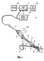
- FIG. 1 there is shown a schematic diagram of one embodiment of the presently disclosed electrosurgical system, designated generally by referenced numeral 10, for use with open and/or laparoscopic surgical procedures.
- the electrosurgical system 10 includes an electrosurgical generator 12 that generates electrosurgical energy, and provides the electrosurgical energy via connector 11 (e.g., a cable) to an exemplary electrosurgical instrument 14, shown in FIG. 1 as electrosurgical bipolar forceps. It is envisioned that the features and concepts (or portions thereof) of the present disclosure can be applied to any electrosurgical type of instrument, including monopolar or bipolar, e.g., pencil, suction coagulator, vessel sealer, etc. In the drawings and in the description which follows, the term “proximal”, as is traditional, will refer to the end of the instrument 14 which is closer to the operator, while the term “distal” will refer to the end which is further from the operator.
- a control unit 13 is provided for controlling aspects of the electrosurgical generator 12 and/or the electrosurgical instrument 14. It is to be appreciated that the generator 12 and control 13 may be disposed in a single housing.
- the instrument 14 includes forceps 16, including a pair of elongated shafts 18, 20 affixed to one another at a pivot point.
- Each shaft 18, 20 includes a proximal end 19 and 21 and a distal end 23 and 25, respectively.
- the proximal end 19, 21 of each shaft 18, 20 is provided with a handle member 22, 24, respectively, attached thereto to allow the operator to effect movement of at least one of the shafts 18, 20 relative to one another.
- Extending from the distal end 23, 25 of each shaft 18, 20 are end effectors 26, 28, respectively.
- the end effectors 26, 28 are movable relative to one another in response to movement of handle members 22 and 24. In embodiments in which the instrument 14 is monopolar there is one end effector.
- An electrode assembly 30 is provided including delivery electrode 33, where a return electrode 31 and the delivery electrode 33 are provided at respective inner facing surfaces 27, 29 of respective distal ends 23, 25 of respective shafts 18, 20. It is envisioned that in other embodiments the electrodes 31, 33 may be positioned on strategically selected surface(s) of the one or more end effectors in accordance with the application. For monopolar embodiments, a return electrode assembly is typically placed at a convenient place on the patient's body and is attached to the generator by a conductive material.
- the electrodes 31, 33 include electrodes selected from a variety of electrodes, such as, "snare", “blade”, “loop”, “needle " and/or "ball” electrodes.
- the delivery electrode 33 delivers the electrosurgical energy to the patient at a delivery point 40, e.g., the point on the electrode assembly 30 that contacts the patient, of a contact surface 42 of the delivery electrode 33 which is formed of a conductive material.
- the configuration of the contact surface 42 may be selected from a variety of configurations, in accordance with the variety of electrode used and the surgical application being performed.
- a schematic representation of internal continuity test circuitry 200 is shown in a cut away and exploded portion of electrode assembly 30 for testing continuity between the delivery electrode 33 and the electrosurgical generator 12 for assuring proper delivery of electrosurgical energy to the delivery point 40.
- the continuity test circuitry 200 may be positioned at various locations, including in the electrosurgical generator 12 or in the electrosurgical instrument 14 (e.g., near a proximal or distal end of the electrosurgical instrument 14, along the end effector 28, etc.) or a combination thereof. In a preferred embodiment, the continuity test circuitry 200 is positioned in the electrosurgical generator 12 to verify the electrical continuity from the generator 12 to the electrosurgical instrument in addition to testing the continuity of the generator 12 to the delivery electrode 33.
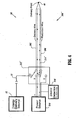
- FIG. 2 schematically shows components of the electrosurgical system 10 related to delivery of electrosurgical energy, continuity testing and control thereof, including a first embodiment of the continuity test circuitry 200.
- a portion of the continuity test circuitry 200 may be integrated within the electrode assembly 30.
- Electrosurgical energy is conducted via a delivery wire 202 to delivery point 40 of an electrode of the electrode assembly 30.
- the electrode assembly 30 is preferably disposed within a housing of the electrosurgical instrument 14, where the delivery point 40 is exposed from the housing.
- the continuity test circuitry 200 may be configured to test any conductor of a variety of conductors that may be included in the electrode assembly 30.
- the continuity test circuitry 200 is configured to test the delivery wire 202 at a point close to the delivery point 40 or at the delivery point 40.
- At least one redundant wire 206 e.g., an additional wire for forming the test circuit
- the redundant wire 206 is connected to the delivery wire 202 at or near the delivery point 40.
- at least one of the at least one additional wire may be used instead of the redundant wire 206, such as in the embodiment described below with reference to FIG. 3.
- the continuity test circuitry 200 preferably includes a test power source 210, coupling circuitry 212, and energy detection circuitry 216.
- the delivery wire 202 e.g., a first conductor
- the at least one redundant wire 206 e.g., a second conductor
- the delivery wire 202 and redundant wire 206 each include conduits for propagating electrical energy, including, but not limited to, metal conductive wires. Voltage is applied across the delivery wire 202 and the redundant wire 206 by the test power source 210, so that when continuity exists current flows through the delivery wire 202 and the redundant wire 206 via a closed test path 214. Detection of the current flow indicates continuity.
- the test path 214 is shown by dotted lines representing a conceptual path followed by the test energy as the test energy flows through the physical components of the continuity test circuitry 200.
- the energy detection circuitry 216 detects the flow of the test energy along the test path 214.
- the continuity test circuitry 200 may optionally further include switching circuitry 220 for selectively opening the test path 214. Furthermore, the continuity test circuitry 200 may optionally be controlled by a control module 230 for controlling the flow of the test energy in accordance with a predetermined condition.
- the test power source 210 which generates the test energy may be- a direct current source or an alternating current source.
- the test power source 210 is preferably a battery sized for integration into the electrosurgical generator 12 or the electrosurgical instrument 14.
- the test power source 210 may be an AC or DC source provided externally from the continuity test circuitry 200, such as a power source providing power to another system. Connectors may be provided for electrically connecting the test power source 210 to the continuity test circuitry 200.
- the test energy provided by the test power source 210 is preferably a low voltage, where the voltage is sufficiently high enough for detection when the test path 214 is closed, yet is minimized for reducing power consumption and the generation of undesirable entities such as noise or heat. It is preferable that the test energy is substantially lower than the energy generated by the electrosurgical generator 12.
- the coupling circuitry 212 is preferably located at or close to the delivery point 40 and may include an electrical connector for providing an electrical path between the delivery wire 202 and the generator 12 and between the redundant wire 206 and the generator 12.
- the energy detection circuitry 216 includes circuitry capable of detecting electrical energy, such as a current detector or voltage detector and outputting a result signal indicative of sensed energy.
- the energy detection circuitry 216 is placed at a point along the test path 214, and preferably is not connected directly to the delivery wire 202 for not placing a load on the delivery wire 202 during a surgical procedure. It is preferable for the energy detection circuitry 216 to be placed in or near the electrosurgical generator 12.
- the energy detection circuitry 216 which may include an optocoupler or other coupling means, is preferably coupled to the redundant wire 206 for detecting the current flow along the redundant wire 206, while providing electrical isolation between circuitry for delivering electrosurgical energy (e.g., circuitry that is in patient contact) and the test energy.
- the optocoupler includes Light Emitting Diode (LED) circuitry for sensing and converting test energy flowing through the redundant wire 206 (preferably electrical energy) into light energy and photo detector circuitry spaced from and aligned with the LED circuitry for detecting light emitted from the LED circuitry and generating the result signal indicative of energy sensed.
- LED Light Emitting Diode
- the result signal indicates the outcome of the continuity test.
- the result signal is provided to at least one indicator provided with the electrode assembly 30, the electrosurgical instrument 14, the electrosurgical generator 12 and/or the control unit 13, such as at least one display device 246, at least one indicator light and/or an audio indicator for indicating the status of the continuity test to a user, particularly when the continuity test has failed.
- the result signal may be provided to the control module 230.
- the switching circuitry 220 is provided along the test path 214 for selectively opening the test path 214 so that the test energy does not flow throughout the test path 214, and particularly so that the test energy does not flow when a continuity test is not being performed. More specifically, the switching circuitry 220 opens the test path 214 during a surgical procedure so that test energy is not delivered to the patient, is not sensed or measured during the surgical procedure, and does not otherwise interfere with the procedure, and/or so that the continuity test circuitry 200 is not detecting energy during the surgical procedure.
- the present disclosure is not limited to opening the test path during a surgical procedure, and it is contemplated that the test energy may be permitted to flow during a surgical procedure; however it is expected that the generator 12 would be disabled during the continuity test.
- the switching circuitry 220 may be strategically located in at least one location, such as along the delivery wire 202 for opening up the test path 214 along the delivery wire 202, as shown in FIG. 2, along the redundant wire 206 for opening up the test path 214 along the redundant wire 206, in the electrosurgical instrument 14, in the electrosurgical generator 12, included in the continuity test circuitry 200, included in the coupling circuitry for opening up the test path that flows through the coupling circuitry 212, included in the energy detection circuitry 216 for disabling detection of test energy, within the test power source 210 for discontinuing flow of the test energy into the continuity test circuitry 200 or any combination thereof.
- the switching circuitry 220 is preferably software controlled by the control module 230 in accordance with a predetermined condition (e.g., a user request, a sensed condition, a system generated request, etc.).
- Control module 230 receives and processes an electrode present signal- from a detector means 240, and/or a user or system generated request signal for initiating a continuity test, and generates an enable continuity test signal upon receipt thereof.
- Generation of the electrode present signal by the detector means 240 indicates that an electrode assembly 30 has been mounted on the electrosurgical instrument 14 or that an electrode has been coupled to the generator.
- the user request signal may be generated by user operation of a user input device 250, where the user input device may include one or more devices, such as a keyboard, button, etc., associated with and/or integrated into the electrosurgical generator 12, the electrosurgical instrument 14, control unit 13 and/or electrode assembly 30.
- the control module 230 may control the electrosurgical generator 12, e.g., prevent generation of electrosurgical energy by the electrosurgical generator 12, upon receipt of an enable continuity test signal and/or throughout the continuity test (e.g., until a successful result signal is received by the control module 230). Furthermore, the control module 230 may receive and process the result signal generated by the energy detection circuitry 216, such as for generating a message to be displayed on the display device 246, and/or for controlling the electrosurgical generator 12, e.g., preventing generation of electrosurgical energy by the electrosurgical generator 12 when the result signal indicates a failure, etc.
- the electrosurgical generator 12 and the test power source 210 are not referenced to the same point so that electrosurgical energy does not flow throughout the test path 214 during a surgical procedure or during a continuity test and the electrosurgical energy does not interfere with operation of the test power source 210.
- the electrosurgical energy follows a path different from the test path 214, in which the electrosurgical energy flows from the delivery electrode 33 to the return electrode 31. It follows that disablement of the electrosurgical generator 12 would not be required during a continuity test, however, it is expected that the generator 12 would be disabled during the continuity test.
- the control module 230 may include one or more software modules, each software module including a series of programmable instructions executable by at least one processor.
- the one or more software modules executable by the at least one processor include a continuity test enable software module, which receives and processes the electrode present signal and generates the enable continuity test signal as described below.
- the one or more software modules may further include a disable electrosurgical generator module, which receives and processes the result signal generated by the energy detection circuitry 216 and generates a disable signal which is provided to the electrosurgical generator 12 for preventing the electrosurgical generator 12 from generating electrosurgical energy when the continuity test fails.
- the control module 230 may include analog circuitry, logic circuitry, firmware, at least one processor of the at least one processor, etc., or a combination thereof. At least one processor of the at least one processors may be included in control unit 13 conventionally provided for controlling the electrosurgical generator and/or instrument.
- the detector means 240 includes a sensor and/or circuitry for detecting the presence of mounted electrode assembly 30 and generating the electrode present signal.
- Detector means 240 may include, for example, a first electrical contact or equivalent that mates with a second electrical contact or equivalent provided on the electrode assembly 30.
- Circuitry is provided for transmitting the electrode present signal to the control unit 13.
- Information indicating the type of electrode assembly 30 mounted on the electrosurgical instrument may further be provided to the control module 230 for the control module 230 to configure the continuity test to be congruent with the configuration of the electrode assembly 30 presently mounted.
- the enable continuity test signal enables the continuity test circuitry 200 to perform a continuity test.
- the enable continuity test signal may control operation of the test power source 210 and/or the switching circuitry 220. For example, when the continuity test signal does not enable the continuity test circuitry 200 to perform the continuity test (e.g., the continuity test signal is "low"), the test power source 210 is turned off and/or the switching circuitry 220 opens the test path 214 so that test energy does not flow, and when the continuity test signal enables the continuity test circuitry 200 to perform the continuity test (e.g., the continuity test signal is "high"), the test power source 210 is turned on and/or the switching circuitry 220 closes the test path 214 so that the test energy may flow through a closed path if the electrode is connected for proper continuity as required for proper application of electrosurgical energy.
- the control module 230 In operation, upon mounting an electrode assembly 30 onto the electrosurgical instrument 14, the presence of the electrode assembly 30 is automatically sensed and an electrode present signal is generated by the detection means 240.
- the control module 230 generates a continuity test enable signal for enabling the continuity test circuitry 200 to perform a continuity test.
- the continuity test is performed one time when the test is successful (e.g., result signal generated by the energy detection circuitry 216 is "high"), but is not limited thereto.
- the continuity test fails (e.g., result signal generated by the energy detection circuitry 216 is "low"), the continuity test may be discontinued and a failure indication is provided to the user, or the continuity test may be continued until the continuity test is successful.
- the continuity test is discontinued before beginning an electrosurgical procedure.
- the continuity test is transparent to the user unless the continuity test fails. The user is not burdened with administering, discontinuing or monitoring the results of the continuity test.
- the continuity test circuitry 200 is preferably disposed in or proximate the electrosurgical generator 12.
- the test power source 210, coupling circuitry 212, energy detection circuitry 216 and switching circuitry 220 are all disposed in or on the electrosurgical generator 12.
- the continuity test circuitry 200 may derive test power from an existing power source providing power to the electrosurgical generator 12, and thus, the test power source 210 may be eliminated.
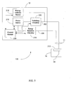
- FIG. 3 A detailed diagram of a second embodiment of the continuity test circuitry 200' is shown in FIG. 3.
- the electrode assembly 30 is further provided with additional circuitry, shown in this example as temperature sensing circuitry 300, including a pair of additional conductive wires 306, 308 (e.g., second conductors), configured as temperature sensors in the example shown, and more specifically as exemplary thermocouple wires, but not limited thereto, and temperature measuring circuitry 310 coupled to the thermocouple wires for measuring the temperature sensed by the thermocouple wires, the thermocouple measuring circuit 310 being preferably disposed in the generator 12.
- additional circuitry shown in this example as temperature sensing circuitry 300, including a pair of additional conductive wires 306, 308 (e.g., second conductors), configured as temperature sensors in the example shown, and more specifically as exemplary thermocouple wires, but not limited thereto, and temperature measuring circuitry 310 coupled to the thermocouple wires for measuring the temperature sensed by the thermocouple wires, the thermocouple measuring circuit
- the additional circuitry is not limited to temperature sensing circuitry, and may include one or more additional conductive wires as well as other elements providing additional functions to the electrosurgical system 10, provided that the at least one of the one or more additional conductive wires may be included in the continuity test circuitry 200' for completing test path 214'.
- Second switching circuitry 320 is provided along the additional conductive wires 306, 308 for selecting at least one, and preferably only one, of the additional conductive wires 306, 308 to be included in the test path 214' for testing electrical conductivity and/or thermocouple function of the selected additional conductive wire 306, 308 within the test path.
- the second switching circuitry 320 in a first position, includes additional conductive wire 306 (but not 308) in the test path 214', and in a second position, the second switching circuitry 320 includes additional conductive wire 308 (but not 306) in the test path.
- the second switching circuitry 320 is not required as long as at least one of the one or more additional conductive wires is included in the test path 214'. Redundant wire 206 shown in FIG. 2 is not included, as the additional conductive wires 306, 308 perform the function of the second conductor provided by the redundant wire 206.
- the control module 230 may generate control signals for controlling the second switching circuitry 320, such as for controlling which additional conductive wire 306 or 308 is selected to be included in the test path 214', such as by selecting the appropriate additional conductive wire in accordance with a predetermined condition (e.g., a user request, results of a previous continuity test, a system request, a sensed condition, etc.).
- a predetermined condition e.g., a user request, results of a previous continuity test, a system request, a sensed condition, etc.
- the control module 230 may test the additional conductive wires in sequence by sequencing to a subsequent additional conductive wire when a continuity test is completed on currently tested additional conductive wire. Results of the continuity tests may be provided to a user, such as via a display or a printout.
- thermocouple wires 306, 308 of temperature sensing circuitry 300 are also verified for continuity.
- an additional indicator may be provided to alert the user of the thermocouple continuity.
- FIG. 4 A detailed diagram of a third embodiment of the continuity test circuitry 200" is shown in FIG. 4.
- coupling circuitry 212" is provided for coupling the electrode assembly 30 to the generator 12 and includes switching circuitry for opening and closing the test path 214".
- the coupling circuitry 212" is operable for delivery of electrosurgical energy to the delivery wire 202 in a first position, and for forming a closed conceptual test path 214" between the delivery wire 202, redundant wire 206 and test power source 210 in a second position.
- the electrosurgical generator 12 is coupled to the delivery wire 202 for delivering electrosurgical energy to the delivery point 40.
- an end of the redundant wire 206 opposite the end coupled to the delivery wire 202 is decoupled, e.g., forming an open circuit, from the test power source 210, so as to avoid energy from the electrosurgical generator 12 being fed into the test power source 210.
- the electrosurgical energy substantially does not interfere with performance of continuity tests
- the test energy substantially does not interfere with delivery of electrosurgical energy to the patient, even when the electrosurgical generator 12 and the test power source 10 are referenced to the same point, and/or are simultaneously enabled.
- the delivery wire 202 is decoupled from the electrosurgical generator 12 and coupled to the test power source 210, and the redundant wire 206 is coupled to the test power source 210 for forming the test path 214".
- the coupling circuitry 212" is a double-pole, double-throw relay.
- the control module 230 and detection means 240 may further be provided, such as for controlling the coupling circuitry 212" including selecting operation in the first or second position, such as in accordance with the enable continuity test signal or user requests.
- the control module 230 may provide further control functions, such as receiving signals, such as result signals from the energy detection circuitry 216 and/or user request signals, and/or providing control signals to the electrosurgical generator 12.
- an electrosurgical system 100 having an exemplary configuration in which at least a portion of the continuity test circuitry 200 is included in the electrosurgical generator 12.
- the test power source 210, energy detection circuitry 216, and switching circuitry 220 are disposed within and/or integrated with the electrosurgical generator 12.
- the redundant wire 206 and the delivery wire 202 extend from the electrosurgical generator 12, through connector 11 and the electrosurgical instrument 14 to the coupling circuitry 212, which preferably positioned proximate the delivery point 40.
- the delivery wire 202 further extends to the delivery point 40 for delivering the electrosurgical energy to the patient via a delivery electrode (such as delivery electrode 33 of FIG. 1).
- a return electrode (not shown) is provided for providing a return path to the electrosurgical energy, where the return electrode may be provided in a bipolar or monopolar configuration.
- the control module 230 may be in communication with the electrosurgical generator 12 and/or the components of the continuity test circuitry 200 for receiving signals, such as result signals from the energy detection circuitry 216 and/or user request signals, and/or for providing control signals, such as to the switching circuitry 220 and/or the electrosurgical generator 12.
Abstract
Description
Claims (26)
- A continuity test circuit assembly for testing electrical continuity between an electrosurgical generator generating electrosurgical energy and an electrode of at least one electrode of an electrosurgical instrument for receiving the electrosurgical energy and delivering the electrosurgical energy to tissue, the continuity test circuit assembly comprising:a first conductor coupling the electrode to the electrosurgical generator;at least one second conductor in electrical communication with a test power source providing electrical test energy and with the electrode for forming a test path;energy detection circuitry positioned along the test path for detecting the flow of the test energy through the test path for determining continuity status;switching circuitry positioned along the test path for selectively closing the test path for enabling a flow of test energy through the test path; anda control module for controlling the switching circuitry for controlling flow of the test energy through the test path.
- A continuity test circuit assembly according to claim 1, further comprising:a detector which detects at least one predetermined condition, and wherein the control module controls the switching circuitry upon detection of the at least one predetermined condition by the detector.
- A continuity test circuit assembly according to claim 2, wherein the at least one predetermined condition which is detected includes mounting of the electrode on the electrosurgical instrument, and wherein the control processor assembly controls the switching circuitry to close the test path upon detection of the at least one predetermined condition.
- A continuity test circuit assembly according to claim 2 or 3, wherein the at least one predetermined condition which is detected includes delivery of electrosurgical energy to the electrode, and wherein the control module controls the switching circuitry to open the test path upon detection of the at least one predetermined condition.
- A continuity test circuit assembly according to claim 2, 3 or 4, wherein the switching circuitry further selectively enables delivery of the electrosurgical energy to the patient, and the control module controls the switching circuitry to open the test path upon detection of the at least one predetermined condition.
- A continuity test circuit assembly according to any one of the preceding claims, wherein the energy detection circuitry provides electrical isolation to the test energy from circuitry through which electrosurgical energy flows.
- A continuity test circuit assembly according to any one of the preceding claims, further comprising second switching circuitry for selecting one of the at least one second conductors to be included in the test path.
- A continuity test circuit assembly according to claim 7, wherein the control module controls the second switching circuitry at least partially in accordance with detection of the predetermined condition.
- A continuity test circuit assembly according to any one of the preceding claims, wherein the at least one second conductor includes at least a pair of thermocouple wires.
- A continuity test circuit assembly according to any one of the preceding claims, wherein the switching circuitry is provided along at least one of the first conductor, the at least one second conductor and the test power source.
- A continuity test circuit assembly according to any one of the preceding claims, wherein at least one of the test power source, energy detection circuitry and the switching circuitry are disposed within the electrosurgical generator.
- A continuity test circuit assembly according to any one of the preceding claims, wherein the test power source derives power from a power source of the electrosurgical generator.
- A continuity test circuit assembly according to any one of the preceding claims, wherein the test energy provided by the test power source is substantially lower than the energy delivered by the electrosurgical generator.
- An electrosurgical generator for generating electrosurgical energy which is provided to an electrosurgical instrument having at least one electrode for delivery of the electrosurgical energy to tissue, the electrosurgical generator comprising:a continuity test circuit assembly for testing electrical continuity between the electrosurgical generator and an electrode of the at least one electrode of the electrosurgical instrument, the continuity test circuit assembly comprising:a test power source providing electrical test energy to a first conductor which is in electrical communication with the electrode and the electrosurgical generator and to at least one second conductor which is coupled to the first conductor for providing a path for current to flow between the first conductor and the at least one second conductor for establishing a test path through which the test energy flows between the first conductor and at least one conductor of the at least one second conductor; andenergy detection circuitry positioned along the test path for detecting the flow of the test energy through the test path for determining electrical continuity through the electrode.
- An electrosurgical generator according to claim 14, wherein the continuity test circuit assembly further comprises:switching circuitry positioned along the test path for selectively disrupting flow of the test energy through the test path; anda control module for controlling the switching circuitry for controlling flow of the test energy through the test path.
- An electrosurgical generator according to claim 15, wherein the control module controls the switching circuitry upon detection of at least one predetermined condition.
- An electrosurgical generator according to claim 16, wherein the at least one predetermined condition includes detection of mounting of the electrode on the electrosurgical instrument, and wherein the control module controls the switching circuitry to close the test path upon detection of the at least one predetermined condition.
- An electrosurgical generator according to claim 16 or 17, wherein the at least one predetermined condition which includes detection of delivery of electrosurgical energy to the electrode, and wherein the control module controls the switching circuitry to open the test path upon detection of the at least one predetermined condition.
- An electrosurgical generator according to claim 16, 17 or 18, wherein the switching circuitry selectively enables delivery of the electrosurgical energy to the tissue, and the control module controls the switching circuitry to open the test path upon detection of the at least one predetermined condition.
- An electrosurgical generator according to any one of claims 14 to 19, wherein the energy detection circuitry provides electrical isolation to the test energy from circuitry through which electrosurgical energy flows.
- An electrosurgical generator according to any one of claims 14 to 20, wherein the continuity test circuit assembly further comprises second switching circuitry for selecting one of the at least one second conductors to be included in the test path.
- An electrosurgical generator according to claim 21, as dependent on claim 15, wherein the control module controls the switching circuitry at least partially in accordance with detection of the predetermined condition.
- An electrosurgical generator according to any one of claims 14 to 22, wherein the at least one second conductor includes at least a pair of thermocouple wires.
- A method for testing continuity between an electrosurgical generator generating electrosurgical energy and an electrode for receiving the electrosurgical energy and delivering the electrosurgical energy to tissue comprising the steps of:applying a test energy to a first conductor coupled between the electrosurgical generator and the electrode and at least one second conductor;coupling the at least one second conductor to the first conductor for providing a path for current to flow between the first conductor and the at least one second conductor for establishing a test path through which the test energy flows between the first conductor and at least one of the at least one second conductor; anddetecting a flow of electrical test energy along the test path, the flow being indicative of continuity status.
- A method according to claim 24, further comprising the step of selectively opening the test path for disrupting the flow of the test energy along the test path.
- A method according to claim 25, further comprising the step of selecting a conductor of the at least one second conductor for coupling to the first conductor in accordance with a predetermined condition.
Applications Claiming Priority (2)
| Application Number | Priority Date | Filing Date | Title |
|---|---|---|---|
| US54387704P | 2004-02-12 | 2004-02-12 | |
| US543877P | 2004-02-12 |
Publications (2)
| Publication Number | Publication Date |
|---|---|
| EP1566645A2 true EP1566645A2 (en) | 2005-08-24 |
| EP1566645A3 EP1566645A3 (en) | 2006-07-19 |
Family
ID=34710269
Family Applications (1)
| Application Number | Title | Priority Date | Filing Date |
|---|---|---|---|
| EP05002769A Withdrawn EP1566645A3 (en) | 2004-02-12 | 2005-02-10 | Method and system for continuity testing of medical electrodes |
Country Status (5)
| Country | Link |
|---|---|
| US (1) | US7766905B2 (en) |
| EP (1) | EP1566645A3 (en) |
| JP (1) | JP4827419B2 (en) |
| AU (1) | AU2005200607B2 (en) |
| CA (1) | CA2496431A1 (en) |
Cited By (11)
| Publication number | Priority date | Publication date | Assignee | Title |
|---|---|---|---|---|
| EP1778111A2 (en) * | 2004-07-20 | 2007-05-02 | Team Medical, L.L.C. | Multielectrode electrosurgical instrument |
| US7867226B2 (en) | 2005-06-30 | 2011-01-11 | Microline Surgical, Inc. | Electrosurgical needle electrode |
| US7867225B2 (en) | 2005-06-30 | 2011-01-11 | Microline Surgical, Inc | Electrosurgical instrument with needle electrode |
| US7896875B2 (en) | 2004-07-20 | 2011-03-01 | Microline Surgical, Inc. | Battery powered electrosurgical system |
| US7935113B2 (en) | 2005-06-30 | 2011-05-03 | Microline Surgical, Inc. | Electrosurgical blade |
| US8562603B2 (en) | 2005-06-30 | 2013-10-22 | Microline Surgical, Inc. | Method for conducting electrosurgery with increased crest factor |
| EP2827466A3 (en) * | 2013-03-04 | 2016-05-04 | Phoenix Contact GmbH & Co. KG | Switching assembly |
| EP3506509A1 (en) * | 2017-12-28 | 2019-07-03 | Ethicon LLC | Surgical instrument with environment sensing |
| WO2019243379A1 (en) * | 2018-06-21 | 2019-12-26 | Adaptive Regelsysteme Gesellschaft M.B.H. | Protective device against electric shocks |
| CN111819794A (en) * | 2017-12-28 | 2020-10-23 | 爱惜康有限责任公司 | Surgical instrument with environmental sensing |
| FR3129490A1 (en) * | 2021-11-25 | 2023-05-26 | Nexans | ELECTRIC CABLE ANTI-THEFT DEVICE AND ASSOCIATED METHOD OF OPERATION |
Families Citing this family (179)
| Publication number | Priority date | Publication date | Assignee | Title |
|---|---|---|---|---|
| US7901400B2 (en) | 1998-10-23 | 2011-03-08 | Covidien Ag | Method and system for controlling output of RF medical generator |
| US7137980B2 (en) | 1998-10-23 | 2006-11-21 | Sherwood Services Ag | Method and system for controlling output of RF medical generator |
| US7364577B2 (en) | 2002-02-11 | 2008-04-29 | Sherwood Services Ag | Vessel sealing system |
| WO2003092520A1 (en) | 2002-05-06 | 2003-11-13 | Sherwood Services Ag | Blood detector for controlling anesu and method therefor |
| US7044948B2 (en) | 2002-12-10 | 2006-05-16 | Sherwood Services Ag | Circuit for controlling arc energy from an electrosurgical generator |
| US7722601B2 (en) | 2003-05-01 | 2010-05-25 | Covidien Ag | Method and system for programming and controlling an electrosurgical generator system |
| US8104956B2 (en) | 2003-10-23 | 2012-01-31 | Covidien Ag | Thermocouple measurement circuit |
| AU2003284929B2 (en) | 2003-10-23 | 2010-07-22 | Covidien Ag | Redundant temperature monitoring in electrosurgical systems for safety mitigation |
| US7396336B2 (en) | 2003-10-30 | 2008-07-08 | Sherwood Services Ag | Switched resonant ultrasonic power amplifier system |
| US7131860B2 (en) | 2003-11-20 | 2006-11-07 | Sherwood Services Ag | Connector systems for electrosurgical generator |
| US7766905B2 (en) | 2004-02-12 | 2010-08-03 | Covidien Ag | Method and system for continuity testing of medical electrodes |
| US7780662B2 (en) | 2004-03-02 | 2010-08-24 | Covidien Ag | Vessel sealing system using capacitive RF dielectric heating |
| US7628786B2 (en) | 2004-10-13 | 2009-12-08 | Covidien Ag | Universal foot switch contact port |
| US10130801B1 (en) | 2005-02-07 | 2018-11-20 | Ipventure, Inc. | Electronic transdermal chemical delivery |
| US8197472B2 (en) | 2005-03-25 | 2012-06-12 | Maquet Cardiovascular, Llc | Tissue welding and cutting apparatus and method |
| US7918848B2 (en) | 2005-03-25 | 2011-04-05 | Maquet Cardiovascular, Llc | Tissue welding and cutting apparatus and method |
| US9474564B2 (en) | 2005-03-31 | 2016-10-25 | Covidien Ag | Method and system for compensating for external impedance of an energy carrying component when controlling an electrosurgical generator |
| JP4871559B2 (en) * | 2005-09-27 | 2012-02-08 | コヴィディエン・アクチェンゲゼルシャフト | Cooling RF ablation needle |
| US8734438B2 (en) | 2005-10-21 | 2014-05-27 | Covidien Ag | Circuit and method for reducing stored energy in an electrosurgical generator |
| US7947039B2 (en) | 2005-12-12 | 2011-05-24 | Covidien Ag | Laparoscopic apparatus for performing electrosurgical procedures |
| CA2575392C (en) | 2006-01-24 | 2015-07-07 | Sherwood Services Ag | System and method for tissue sealing |
| CA2574934C (en) | 2006-01-24 | 2015-12-29 | Sherwood Services Ag | System and method for closed loop monitoring of monopolar electrosurgical apparatus |
| US8216223B2 (en) | 2006-01-24 | 2012-07-10 | Covidien Ag | System and method for tissue sealing |
| US8685016B2 (en) | 2006-01-24 | 2014-04-01 | Covidien Ag | System and method for tissue sealing |
| CA2574935A1 (en) | 2006-01-24 | 2007-07-24 | Sherwood Services Ag | A method and system for controlling an output of a radio-frequency medical generator having an impedance based control algorithm |
| US9186200B2 (en) | 2006-01-24 | 2015-11-17 | Covidien Ag | System and method for tissue sealing |
| US7513896B2 (en) | 2006-01-24 | 2009-04-07 | Covidien Ag | Dual synchro-resonant electrosurgical apparatus with bi-directional magnetic coupling |
| US8147485B2 (en) | 2006-01-24 | 2012-04-03 | Covidien Ag | System and method for tissue sealing |
| US7651493B2 (en) | 2006-03-03 | 2010-01-26 | Covidien Ag | System and method for controlling electrosurgical snares |
| US7648499B2 (en) | 2006-03-21 | 2010-01-19 | Covidien Ag | System and method for generating radio frequency energy |
| US7651492B2 (en) | 2006-04-24 | 2010-01-26 | Covidien Ag | Arc based adaptive control system for an electrosurgical unit |
| US8753334B2 (en) | 2006-05-10 | 2014-06-17 | Covidien Ag | System and method for reducing leakage current in an electrosurgical generator |
| US7731717B2 (en) | 2006-08-08 | 2010-06-08 | Covidien Ag | System and method for controlling RF output during tissue sealing |
| US8034049B2 (en) | 2006-08-08 | 2011-10-11 | Covidien Ag | System and method for measuring initial tissue impedance |
| US7637907B2 (en) * | 2006-09-19 | 2009-12-29 | Covidien Ag | System and method for return electrode monitoring |
| US7794457B2 (en) | 2006-09-28 | 2010-09-14 | Covidien Ag | Transformer for RF voltage sensing |
| US8777941B2 (en) | 2007-05-10 | 2014-07-15 | Covidien Lp | Adjustable impedance electrosurgical electrodes |
| CN101686834A (en) * | 2007-07-13 | 2010-03-31 | 波士顿科学医学有限公司 | Hybrid and portable power supplies for electrolytically detaching implantable medical devices |
| US7834484B2 (en) | 2007-07-16 | 2010-11-16 | Tyco Healthcare Group Lp | Connection cable and method for activating a voltage-controlled generator |
| US8216220B2 (en) | 2007-09-07 | 2012-07-10 | Tyco Healthcare Group Lp | System and method for transmission of combined data stream |
| JP4904470B2 (en) * | 2007-09-19 | 2012-03-28 | 富士フイルム株式会社 | Observation image forming apparatus |
| US8512332B2 (en) | 2007-09-21 | 2013-08-20 | Covidien Lp | Real-time arc control in electrosurgical generators |
| US9402680B2 (en) | 2008-05-27 | 2016-08-02 | Maquet Cardiovasular, Llc | Surgical instrument and method |
| US8226639B2 (en) | 2008-06-10 | 2012-07-24 | Tyco Healthcare Group Lp | System and method for output control of electrosurgical generator |
| US8262652B2 (en) | 2009-01-12 | 2012-09-11 | Tyco Healthcare Group Lp | Imaginary impedance process monitoring and intelligent shut-off |
| US9603540B2 (en) * | 2009-01-21 | 2017-03-28 | Honeywell International Inc. | Electrode placement for remote monitoring |
| US9955858B2 (en) | 2009-08-21 | 2018-05-01 | Maquet Cardiovascular Llc | Surgical instrument and method for use |
| US8790335B2 (en) * | 2009-08-28 | 2014-07-29 | Covidien Lp | Electrosurgical generator |
| US8652125B2 (en) * | 2009-09-28 | 2014-02-18 | Covidien Lp | Electrosurgical generator user interface |
| US8641708B2 (en) * | 2009-12-29 | 2014-02-04 | Biosense Webster (Israel), Ltd. | Measuring weak signals over ablation lines |
| US9375247B2 (en) | 2011-03-16 | 2016-06-28 | Covidien Lp | System and method for electrosurgical generator power measurement |
| US8968293B2 (en) | 2011-04-12 | 2015-03-03 | Covidien Lp | Systems and methods for calibrating power measurements in an electrosurgical generator |
| US8932291B2 (en) | 2012-04-13 | 2015-01-13 | Covidien Lp | Electrosurgical systems |
| US11871901B2 (en) | 2012-05-20 | 2024-01-16 | Cilag Gmbh International | Method for situational awareness for surgical network or surgical network connected device capable of adjusting function based on a sensed situation or usage |
| US9872719B2 (en) | 2013-07-24 | 2018-01-23 | Covidien Lp | Systems and methods for generating electrosurgical energy using a multistage power converter |
| US9636165B2 (en) | 2013-07-29 | 2017-05-02 | Covidien Lp | Systems and methods for measuring tissue impedance through an electrosurgical cable |
| US11504192B2 (en) | 2014-10-30 | 2022-11-22 | Cilag Gmbh International | Method of hub communication with surgical instrument systems |
| US11660445B2 (en) | 2015-09-23 | 2023-05-30 | Cochlear Limited | Electrode array packaging system |
| US10842531B2 (en) | 2016-06-22 | 2020-11-24 | Cochlear Limited | Electrode insertion tool with additional functionality |
| US11285314B2 (en) | 2016-08-19 | 2022-03-29 | Cochlear Limited | Advanced electrode array insertion |
| WO2018200254A2 (en) | 2017-04-28 | 2018-11-01 | Stryker Corporation | Control console and accessories for rf nerve ablation and methods of operating the same |
| US11129666B2 (en) * | 2017-06-28 | 2021-09-28 | Cilag Gmbh International | Shaft module circuitry arrangements |
| US11058477B2 (en) * | 2017-06-28 | 2021-07-13 | Cilag Gmbh International | Surgical cutting and fastening instruments with dual power sources |
| US10359464B2 (en) * | 2017-09-18 | 2019-07-23 | Biosense Webster (Israel) Ltd. | Cable and associated continuity monitoring system and method |
| US11510741B2 (en) | 2017-10-30 | 2022-11-29 | Cilag Gmbh International | Method for producing a surgical instrument comprising a smart electrical system |
| US11026687B2 (en) | 2017-10-30 | 2021-06-08 | Cilag Gmbh International | Clip applier comprising clip advancing systems |
| US11911045B2 (en) | 2017-10-30 | 2024-02-27 | Cllag GmbH International | Method for operating a powered articulating multi-clip applier |
| US11291510B2 (en) | 2017-10-30 | 2022-04-05 | Cilag Gmbh International | Method of hub communication with surgical instrument systems |
| US11801098B2 (en) | 2017-10-30 | 2023-10-31 | Cilag Gmbh International | Method of hub communication with surgical instrument systems |
| US11229436B2 (en) | 2017-10-30 | 2022-01-25 | Cilag Gmbh International | Surgical system comprising a surgical tool and a surgical hub |
| US11564756B2 (en) | 2017-10-30 | 2023-01-31 | Cilag Gmbh International | Method of hub communication with surgical instrument systems |
| US11129636B2 (en) | 2017-10-30 | 2021-09-28 | Cilag Gmbh International | Surgical instruments comprising an articulation drive that provides for high articulation angles |
| US11317919B2 (en) | 2017-10-30 | 2022-05-03 | Cilag Gmbh International | Clip applier comprising a clip crimping system |
| US11311342B2 (en) | 2017-10-30 | 2022-04-26 | Cilag Gmbh International | Method for communicating with surgical instrument systems |
| US11786245B2 (en) | 2017-12-28 | 2023-10-17 | Cilag Gmbh International | Surgical systems with prioritized data transmission capabilities |
| US11147607B2 (en) | 2017-12-28 | 2021-10-19 | Cilag Gmbh International | Bipolar combination device that automatically adjusts pressure based on energy modality |
| US11308075B2 (en) | 2017-12-28 | 2022-04-19 | Cilag Gmbh International | Surgical network, instrument, and cloud responses based on validation of received dataset and authentication of its source and integrity |
| US11633237B2 (en) | 2017-12-28 | 2023-04-25 | Cilag Gmbh International | Usage and technique analysis of surgeon / staff performance against a baseline to optimize device utilization and performance for both current and future procedures |
| US11304745B2 (en) | 2017-12-28 | 2022-04-19 | Cilag Gmbh International | Surgical evacuation sensing and display |
| US11832899B2 (en) | 2017-12-28 | 2023-12-05 | Cilag Gmbh International | Surgical systems with autonomously adjustable control programs |
| US11389164B2 (en) | 2017-12-28 | 2022-07-19 | Cilag Gmbh International | Method of using reinforced flexible circuits with multiple sensors to optimize performance of radio frequency devices |
| US10944728B2 (en) | 2017-12-28 | 2021-03-09 | Ethicon Llc | Interactive surgical systems with encrypted communication capabilities |
| US11109866B2 (en) | 2017-12-28 | 2021-09-07 | Cilag Gmbh International | Method for circular stapler control algorithm adjustment based on situational awareness |
| US11311306B2 (en) | 2017-12-28 | 2022-04-26 | Cilag Gmbh International | Surgical systems for detecting end effector tissue distribution irregularities |
| US11304763B2 (en) | 2017-12-28 | 2022-04-19 | Cilag Gmbh International | Image capturing of the areas outside the abdomen to improve placement and control of a surgical device in use |
| US10695081B2 (en) | 2017-12-28 | 2020-06-30 | Ethicon Llc | Controlling a surgical instrument according to sensed closure parameters |
| US10758310B2 (en) | 2017-12-28 | 2020-09-01 | Ethicon Llc | Wireless pairing of a surgical device with another device within a sterile surgical field based on the usage and situational awareness of devices |
| US11423007B2 (en) | 2017-12-28 | 2022-08-23 | Cilag Gmbh International | Adjustment of device control programs based on stratified contextual data in addition to the data |
| US11051876B2 (en) | 2017-12-28 | 2021-07-06 | Cilag Gmbh International | Surgical evacuation flow paths |
| US11132462B2 (en) | 2017-12-28 | 2021-09-28 | Cilag Gmbh International | Data stripping method to interrogate patient records and create anonymized record |
| US11744604B2 (en) | 2017-12-28 | 2023-09-05 | Cilag Gmbh International | Surgical instrument with a hardware-only control circuit |
| US11896322B2 (en) | 2017-12-28 | 2024-02-13 | Cilag Gmbh International | Sensing the patient position and contact utilizing the mono-polar return pad electrode to provide situational awareness to the hub |
| US11410259B2 (en) | 2017-12-28 | 2022-08-09 | Cilag Gmbh International | Adaptive control program updates for surgical devices |
| US10987178B2 (en) | 2017-12-28 | 2021-04-27 | Ethicon Llc | Surgical hub control arrangements |
| US11096693B2 (en) | 2017-12-28 | 2021-08-24 | Cilag Gmbh International | Adjustment of staple height of at least one row of staples based on the sensed tissue thickness or force in closing |
| US11589888B2 (en) | 2017-12-28 | 2023-02-28 | Cilag Gmbh International | Method for controlling smart energy devices |
| US20190201146A1 (en) | 2017-12-28 | 2019-07-04 | Ethicon Llc | Safety systems for smart powered surgical stapling |
| US11179208B2 (en) | 2017-12-28 | 2021-11-23 | Cilag Gmbh International | Cloud-based medical analytics for security and authentication trends and reactive measures |
| US11576677B2 (en) | 2017-12-28 | 2023-02-14 | Cilag Gmbh International | Method of hub communication, processing, display, and cloud analytics |
| US11857152B2 (en) | 2017-12-28 | 2024-01-02 | Cilag Gmbh International | Surgical hub spatial awareness to determine devices in operating theater |
| US11317937B2 (en) | 2018-03-08 | 2022-05-03 | Cilag Gmbh International | Determining the state of an ultrasonic end effector |
| US11464559B2 (en) | 2017-12-28 | 2022-10-11 | Cilag Gmbh International | Estimating state of ultrasonic end effector and control system therefor |
| US11069012B2 (en) | 2017-12-28 | 2021-07-20 | Cilag Gmbh International | Interactive surgical systems with condition handling of devices and data capabilities |
| US11903601B2 (en) | 2017-12-28 | 2024-02-20 | Cilag Gmbh International | Surgical instrument comprising a plurality of drive systems |
| US11266468B2 (en) | 2017-12-28 | 2022-03-08 | Cilag Gmbh International | Cooperative utilization of data derived from secondary sources by intelligent surgical hubs |
| US11464535B2 (en) | 2017-12-28 | 2022-10-11 | Cilag Gmbh International | Detection of end effector emersion in liquid |
| US11612444B2 (en) | 2017-12-28 | 2023-03-28 | Cilag Gmbh International | Adjustment of a surgical device function based on situational awareness |
| US11529187B2 (en) | 2017-12-28 | 2022-12-20 | Cilag Gmbh International | Surgical evacuation sensor arrangements |
| US11937769B2 (en) | 2017-12-28 | 2024-03-26 | Cilag Gmbh International | Method of hub communication, processing, storage and display |
| US11666331B2 (en) | 2017-12-28 | 2023-06-06 | Cilag Gmbh International | Systems for detecting proximity of surgical end effector to cancerous tissue |
| US11818052B2 (en) | 2017-12-28 | 2023-11-14 | Cilag Gmbh International | Surgical network determination of prioritization of communication, interaction, or processing based on system or device needs |
| US11273001B2 (en) | 2017-12-28 | 2022-03-15 | Cilag Gmbh International | Surgical hub and modular device response adjustment based on situational awareness |
| US11056244B2 (en) | 2017-12-28 | 2021-07-06 | Cilag Gmbh International | Automated data scaling, alignment, and organizing based on predefined parameters within surgical networks |
| US11253315B2 (en) | 2017-12-28 | 2022-02-22 | Cilag Gmbh International | Increasing radio frequency to create pad-less monopolar loop |
| US11559308B2 (en) | 2017-12-28 | 2023-01-24 | Cilag Gmbh International | Method for smart energy device infrastructure |
| US20190200981A1 (en) | 2017-12-28 | 2019-07-04 | Ethicon Llc | Method of compressing tissue within a stapling device and simultaneously displaying the location of the tissue within the jaws |
| US20190201039A1 (en) | 2017-12-28 | 2019-07-04 | Ethicon Llc | Situational awareness of electrosurgical systems |
| US11364075B2 (en) | 2017-12-28 | 2022-06-21 | Cilag Gmbh International | Radio frequency energy device for delivering combined electrical signals |
| US11419667B2 (en) | 2017-12-28 | 2022-08-23 | Cilag Gmbh International | Ultrasonic energy device which varies pressure applied by clamp arm to provide threshold control pressure at a cut progression location |
| US11234756B2 (en) | 2017-12-28 | 2022-02-01 | Cilag Gmbh International | Powered surgical tool with predefined adjustable control algorithm for controlling end effector parameter |
| US11786251B2 (en) | 2017-12-28 | 2023-10-17 | Cilag Gmbh International | Method for adaptive control schemes for surgical network control and interaction |
| US11166772B2 (en) | 2017-12-28 | 2021-11-09 | Cilag Gmbh International | Surgical hub coordination of control and communication of operating room devices |
| US11291495B2 (en) | 2017-12-28 | 2022-04-05 | Cilag Gmbh International | Interruption of energy due to inadvertent capacitive coupling |
| US10966791B2 (en) | 2017-12-28 | 2021-04-06 | Ethicon Llc | Cloud-based medical analytics for medical facility segmented individualization of instrument function |
| US10755813B2 (en) | 2017-12-28 | 2020-08-25 | Ethicon Llc | Communication of smoke evacuation system parameters to hub or cloud in smoke evacuation module for interactive surgical platform |
| US11540855B2 (en) | 2017-12-28 | 2023-01-03 | Cilag Gmbh International | Controlling activation of an ultrasonic surgical instrument according to the presence of tissue |
| US11424027B2 (en) | 2017-12-28 | 2022-08-23 | Cilag Gmbh International | Method for operating surgical instrument systems |
| US11659023B2 (en) | 2017-12-28 | 2023-05-23 | Cilag Gmbh International | Method of hub communication |
| US11571234B2 (en) | 2017-12-28 | 2023-02-07 | Cilag Gmbh International | Temperature control of ultrasonic end effector and control system therefor |
| US11202570B2 (en) | 2017-12-28 | 2021-12-21 | Cilag Gmbh International | Communication hub and storage device for storing parameters and status of a surgical device to be shared with cloud based analytics systems |
| US10932872B2 (en) | 2017-12-28 | 2021-03-02 | Ethicon Llc | Cloud-based medical analytics for linking of local usage trends with the resource acquisition behaviors of larger data set |
| US20190201139A1 (en) | 2017-12-28 | 2019-07-04 | Ethicon Llc | Communication arrangements for robot-assisted surgical platforms |
| US11559307B2 (en) | 2017-12-28 | 2023-01-24 | Cilag Gmbh International | Method of robotic hub communication, detection, and control |
| US11896443B2 (en) | 2017-12-28 | 2024-02-13 | Cilag Gmbh International | Control of a surgical system through a surgical barrier |
| US11864728B2 (en) | 2017-12-28 | 2024-01-09 | Cilag Gmbh International | Characterization of tissue irregularities through the use of mono-chromatic light refractivity |
| US11304699B2 (en) | 2017-12-28 | 2022-04-19 | Cilag Gmbh International | Method for adaptive control schemes for surgical network control and interaction |
| US11832840B2 (en) | 2017-12-28 | 2023-12-05 | Cilag Gmbh International | Surgical instrument having a flexible circuit |
| US10892899B2 (en) | 2017-12-28 | 2021-01-12 | Ethicon Llc | Self describing data packets generated at an issuing instrument |
| US11160605B2 (en) | 2017-12-28 | 2021-11-02 | Cilag Gmbh International | Surgical evacuation sensing and motor control |
| US11419630B2 (en) | 2017-12-28 | 2022-08-23 | Cilag Gmbh International | Surgical system distributed processing |
| US11304720B2 (en) | 2017-12-28 | 2022-04-19 | Cilag Gmbh International | Activation of energy devices |
| US10849697B2 (en) | 2017-12-28 | 2020-12-01 | Ethicon Llc | Cloud interface for coupled surgical devices |
| US11257589B2 (en) | 2017-12-28 | 2022-02-22 | Cilag Gmbh International | Real-time analysis of comprehensive cost of all instrumentation used in surgery utilizing data fluidity to track instruments through stocking and in-house processes |
| US11100631B2 (en) | 2017-12-28 | 2021-08-24 | Cilag Gmbh International | Use of laser light and red-green-blue coloration to determine properties of back scattered light |
| US11284936B2 (en) | 2017-12-28 | 2022-03-29 | Cilag Gmbh International | Surgical instrument having a flexible electrode |
| US11045591B2 (en) | 2017-12-28 | 2021-06-29 | Cilag Gmbh International | Dual in-series large and small droplet filters |
| US11446052B2 (en) | 2017-12-28 | 2022-09-20 | Cilag Gmbh International | Variation of radio frequency and ultrasonic power level in cooperation with varying clamp arm pressure to achieve predefined heat flux or power applied to tissue |
| US11179175B2 (en) | 2017-12-28 | 2021-11-23 | Cilag Gmbh International | Controlling an ultrasonic surgical instrument according to tissue location |
| US11678881B2 (en) | 2017-12-28 | 2023-06-20 | Cilag Gmbh International | Spatial awareness of surgical hubs in operating rooms |
| US11278281B2 (en) | 2017-12-28 | 2022-03-22 | Cilag Gmbh International | Interactive surgical system |
| US11602393B2 (en) | 2017-12-28 | 2023-03-14 | Cilag Gmbh International | Surgical evacuation sensing and generator control |
| US10943454B2 (en) | 2017-12-28 | 2021-03-09 | Ethicon Llc | Detection and escalation of security responses of surgical instruments to increasing severity threats |
| US11376002B2 (en) | 2017-12-28 | 2022-07-05 | Cilag Gmbh International | Surgical instrument cartridge sensor assemblies |
| US10892995B2 (en) | 2017-12-28 | 2021-01-12 | Ethicon Llc | Surgical network determination of prioritization of communication, interaction, or processing based on system or device needs |
| US20190201118A1 (en) | 2017-12-28 | 2019-07-04 | Ethicon Llc | Display arrangements for robot-assisted surgical platforms |
| US11076921B2 (en) | 2017-12-28 | 2021-08-03 | Cilag Gmbh International | Adaptive control program updates for surgical hubs |
| US11432885B2 (en) | 2017-12-28 | 2022-09-06 | Cilag Gmbh International | Sensing arrangements for robot-assisted surgical platforms |
| US11589915B2 (en) | 2018-03-08 | 2023-02-28 | Cilag Gmbh International | In-the-jaw classifier based on a model |
| US11389188B2 (en) | 2018-03-08 | 2022-07-19 | Cilag Gmbh International | Start temperature of blade |
| US11259830B2 (en) | 2018-03-08 | 2022-03-01 | Cilag Gmbh International | Methods for controlling temperature in ultrasonic device |
| DE102018105824B3 (en) * | 2018-03-13 | 2019-07-11 | Olympus Winter & Ibe Gmbh | Test device for an electrosurgical generator |
| US11090047B2 (en) | 2018-03-28 | 2021-08-17 | Cilag Gmbh International | Surgical instrument comprising an adaptive control system |
| US11471156B2 (en) | 2018-03-28 | 2022-10-18 | Cilag Gmbh International | Surgical stapling devices with improved rotary driven closure systems |
| US11278280B2 (en) | 2018-03-28 | 2022-03-22 | Cilag Gmbh International | Surgical instrument comprising a jaw closure lockout |
| US11259806B2 (en) | 2018-03-28 | 2022-03-01 | Cilag Gmbh International | Surgical stapling devices with features for blocking advancement of a camming assembly of an incompatible cartridge installed therein |
| US10973520B2 (en) | 2018-03-28 | 2021-04-13 | Ethicon Llc | Surgical staple cartridge with firing member driven camming assembly that has an onboard tissue cutting feature |
| US11096688B2 (en) | 2018-03-28 | 2021-08-24 | Cilag Gmbh International | Rotary driven firing members with different anvil and channel engagement features |
| US11213294B2 (en) | 2018-03-28 | 2022-01-04 | Cilag Gmbh International | Surgical instrument comprising co-operating lockout features |
| US11219453B2 (en) | 2018-03-28 | 2022-01-11 | Cilag Gmbh International | Surgical stapling devices with cartridge compatible closure and firing lockout arrangements |
| US11207067B2 (en) | 2018-03-28 | 2021-12-28 | Cilag Gmbh International | Surgical stapling device with separate rotary driven closure and firing systems and firing member that engages both jaws while firing |
| US11464511B2 (en) | 2019-02-19 | 2022-10-11 | Cilag Gmbh International | Surgical staple cartridges with movable authentication key arrangements |
| US11357503B2 (en) | 2019-02-19 | 2022-06-14 | Cilag Gmbh International | Staple cartridge retainers with frangible retention features and methods of using same |
| US11369377B2 (en) | 2019-02-19 | 2022-06-28 | Cilag Gmbh International | Surgical stapling assembly with cartridge based retainer configured to unlock a firing lockout |
| US11291444B2 (en) | 2019-02-19 | 2022-04-05 | Cilag Gmbh International | Surgical stapling assembly with cartridge based retainer configured to unlock a closure lockout |
| US11317915B2 (en) | 2019-02-19 | 2022-05-03 | Cilag Gmbh International | Universal cartridge based key feature that unlocks multiple lockout arrangements in different surgical staplers |
| USD950728S1 (en) | 2019-06-25 | 2022-05-03 | Cilag Gmbh International | Surgical staple cartridge |
| USD952144S1 (en) | 2019-06-25 | 2022-05-17 | Cilag Gmbh International | Surgical staple cartridge retainer with firing system authentication key |
| USD964564S1 (en) | 2019-06-25 | 2022-09-20 | Cilag Gmbh International | Surgical staple cartridge retainer with a closure system authentication key |
| TWI693919B (en) * | 2019-07-08 | 2020-05-21 | 國立虎尾科技大學 | Electrical discharge testing method for surgical instruments |
Citations (3)
| Publication number | Priority date | Publication date | Assignee | Title |
|---|---|---|---|---|
| EP0569130A1 (en) | 1992-05-07 | 1993-11-10 | Smiths Industries Public Limited Company | Safety appliance for electrosurgery or welding |
| DE4339049A1 (en) | 1993-11-16 | 1995-05-18 | Erbe Elektromedizin | Surgical system and instruments configuration device |
| US20030225401A1 (en) | 2002-05-31 | 2003-12-04 | Eggers Philip E. | Electrosurgery with infiltration anesthesia |
Family Cites Families (574)
| Publication number | Priority date | Publication date | Assignee | Title |
|---|---|---|---|---|
| DE179607C (en) | 1906-11-12 | |||
| DE390937C (en) | 1922-10-13 | 1924-03-03 | Adolf Erb | Device for internal heating of furnace furnaces for hardening, tempering, annealing, quenching and melting |
| US1841968A (en) | 1924-08-16 | 1932-01-19 | William J Cameron | Radio-surgical apparatus |
| US1863118A (en) | 1927-10-31 | 1932-06-14 | Liebel Flarsheim Co | Surgeon's instrument |
| US1813902A (en) | 1928-01-18 | 1931-07-14 | Liebel Flarsheim Co | Electrosurgical apparatus |
| US1787709A (en) | 1928-06-11 | 1931-01-06 | Wappler Frederick Charles | High-frequency surgical cutting device |
| US1945867A (en) | 1932-04-27 | 1934-02-06 | Technical Equipment Company | High frequency oscillatory apparatus for electrotherapeutic and sterilization purposes |
| GB607850A (en) | 1946-04-01 | 1948-09-06 | William George Curwain | Electric connectors |
| US2849611A (en) | 1955-05-16 | 1958-08-26 | Honeywell Regulator Co | Electrical oscillator circuit |
| US2827056A (en) | 1955-06-21 | 1958-03-18 | Thomas H Ballantine Jr | Electrode discharge control for surgical apparatus |
| BE556940A (en) | 1956-04-26 | |||
| GB855459A (en) | 1958-04-11 | 1960-11-30 | Keeler Optical Products Ltd | Improvements in or relating to electro-surgical apparatus |
| US2982881A (en) | 1958-05-22 | 1961-05-02 | Robert W Reich | Portable light source |
| DE1099658B (en) | 1959-04-29 | 1961-02-16 | Siemens Reiniger Werke Ag | Automatic switch-on device for high-frequency surgical devices |
| GB902775A (en) | 1959-05-16 | 1962-08-09 | Kathleen Zilla Rumble | Improvements in or relating to electrical plugs |
| US3089496A (en) | 1959-08-19 | 1963-05-14 | Code Inc | Control system for surgical apparatus |
| US3163165A (en) | 1960-09-12 | 1964-12-29 | Islkawa Humio | Uterotube-closing instrument |
| FR1275415A (en) | 1960-09-26 | 1961-11-10 | Device for detecting disturbances for electrical installations, in particular electrosurgery | |
| DE1139927B (en) | 1961-01-03 | 1962-11-22 | Friedrich Laber | High-frequency surgical device |
| DE1149832C2 (en) | 1961-02-25 | 1977-10-13 | Siemens AG, 1000 Berlin und 8000 München | HIGH FREQUENCY SURGICAL EQUIPMENT |
| FR1347865A (en) | 1962-11-22 | 1964-01-04 | Improvements to diathermo-coagulation devices | |
| US3252052A (en) | 1963-08-23 | 1966-05-17 | Jacuzzi Bros Inc | Leakage detection and control circuit |
| DE1264513C2 (en) | 1963-11-29 | 1973-01-25 | Texas Instruments Inc | REFERENCE POTENTIAL FREE DC DIFFERENCE AMPLIFIER |
| US3478744A (en) | 1964-12-30 | 1969-11-18 | Harry Leiter | Surgical apparatus |
| US3486115A (en) | 1965-04-01 | 1969-12-23 | Donald J Anderson | Means for measuring the power in an electrical circuit |
| US3439680A (en) | 1965-04-12 | 1969-04-22 | Univ Northwestern | Surgical instrument for cataract removal |
| FR1494065A (en) | 1965-05-10 | 1967-09-08 | Const De Vaux Andigny Atel | Detector-amplifier for low level signals and devices with application |
| US3495584A (en) | 1965-06-03 | 1970-02-17 | Gen Electric | Lead failure detection circuit for a cardiac monitor |
| US3436563A (en) | 1965-12-27 | 1969-04-01 | Bell Telephone Labor Inc | Pulse driver with linear current rise |
| US3471770A (en) | 1966-03-30 | 1969-10-07 | Ibm | Pulsed current generating circuits |
| US3461874A (en) | 1966-08-10 | 1969-08-19 | Miguel Martinez | Electric cautery |
| GB1169706A (en) | 1966-09-29 | 1969-11-05 | English Electric Co Ltd | An Electrical Fault Detector |
| US3391351A (en) | 1966-11-21 | 1968-07-02 | Bell Telephone Labor Inc | Circuits using a transistor operated into second breakdown region |
| US3439253A (en) | 1967-04-05 | 1969-04-15 | R I Phelon Inc | Alternator rectifier and voltage regulator |
| NL145136C (en) | 1967-07-25 | 1900-01-01 | ||
| US3513353A (en) | 1967-08-17 | 1970-05-19 | John L Lansch | Voltage monitoring circuit |
| US3551786A (en) | 1967-12-05 | 1970-12-29 | Omark Industries Inc | Circuit for adjustably increasing or decreasing the charge on a capacitor |
| US3562623A (en) | 1968-07-16 | 1971-02-09 | Hughes Aircraft Co | Circuit for reducing stray capacity effects in transformer windings |
| US3514689A (en) | 1968-08-21 | 1970-05-26 | United Aircraft Corp | Three-phase ac-operated dc power supply |
| US3642008A (en) * | 1968-09-25 | 1972-02-15 | Medical Plastics Inc | Ground electrode and test circuit |
| US3601126A (en) | 1969-01-08 | 1971-08-24 | Electro Medical Systems Inc | High frequency electrosurgical apparatus |
| US3571644A (en) | 1969-01-27 | 1971-03-23 | Heurtey Sa | High frequency oscillator for inductive heating |
| US3595221A (en) | 1969-03-04 | 1971-07-27 | Matburn Holdings Ltd | Endoscopic having illumination supply unit |
| US3611053A (en) | 1969-10-10 | 1971-10-05 | Farmer Electric Products Co In | Intrinsically safe circuit |
| US3662151A (en) | 1969-11-17 | 1972-05-09 | Codman & Shurtleff | Cautery |
| US3675655A (en) | 1970-02-04 | 1972-07-11 | Electro Medical Systems Inc | Method and apparatus for high frequency electric surgery |
| DE2030776A1 (en) | 1970-06-23 | 1971-12-30 | Siemens Ag | Handpiece for high frequency electrodes |
| US3826263A (en) | 1970-08-13 | 1974-07-30 | R Shaw | Electrically heated surgical cutting instrument |
| US3683923A (en) | 1970-09-25 | 1972-08-15 | Valleylab Inc | Electrosurgery safety circuit |
| US3641422A (en) | 1970-10-01 | 1972-02-08 | Robert P Farnsworth | Wide band boost regulator power supply |
| US3697808A (en) | 1970-11-23 | 1972-10-10 | Safety Co The | System for monitoring chassis potential and ground continuity |
| US3693613A (en) | 1970-12-09 | 1972-09-26 | Cavitron Corp | Surgical handpiece and flow control system for use therewith |
| FR2123896A5 (en) | 1971-02-04 | 1972-09-15 | Radiotechnique Compelec | |
| US3699967A (en) | 1971-04-30 | 1972-10-24 | Valleylab Inc | Electrosurgical generator |
| US3766434A (en) | 1971-08-09 | 1973-10-16 | S Sherman | Safety power distribution system |
| US3784842A (en) | 1972-02-03 | 1974-01-08 | F Kremer | Body current activated circuit breaker |
| US3848600A (en) | 1972-02-03 | 1974-11-19 | Ndm Corp | Indifferent electrode in electrosurgical procedures and method of use |
| US3828768A (en) | 1972-07-13 | 1974-08-13 | Physiological Electronics Corp | Method and apparatus for detecting cardiac arrhythmias |
| US3783340A (en) | 1972-09-07 | 1974-01-01 | Biotek Instr Inc | Ground safe system |
| US3768482A (en) | 1972-10-10 | 1973-10-30 | R Shaw | Surgical cutting instrument having electrically heated cutting edge |
| US3812858A (en) | 1972-10-24 | 1974-05-28 | Sybron Corp | Dental electrosurgical unit |
| US3885569A (en) | 1972-11-21 | 1975-05-27 | Birtcher Corp | Electrosurgical unit |
| US3801800A (en) | 1972-12-26 | 1974-04-02 | Valleylab Inc | Isolating switching circuit for an electrosurgical generator |
| JPS5241593B2 (en) | 1972-12-29 | 1977-10-19 | ||
| US3801766A (en) | 1973-01-22 | 1974-04-02 | Valleylab Inc | Switching means for an electro-surgical device including particular contact means and particular printed-circuit mounting means |
| US3971365A (en) | 1973-02-12 | 1976-07-27 | Beckman Instruments, Inc. | Bioelectrical impedance measuring system |
| US3815015A (en) | 1973-02-20 | 1974-06-04 | Gen Electric | Transformer-diode isolated circuits for high voltage power supplies |
| US3963030A (en) | 1973-04-16 | 1976-06-15 | Valleylab, Inc. | Signal generating device and method for producing coagulation electrosurgical current |
| GB1480736A (en) | 1973-08-23 | 1977-07-20 | Matburn Ltd | Electrodiathermy apparatus |
| US3933157A (en) | 1973-10-23 | 1976-01-20 | Aktiebolaget Stille-Werner | Test and control device for electrosurgical apparatus |
| US3875945A (en) | 1973-11-02 | 1975-04-08 | Demetron Corp | Electrosurgery instrument |
| US3870047A (en) | 1973-11-12 | 1975-03-11 | Dentsply Res & Dev | Electrosurgical device |
| DE2455174A1 (en) | 1973-11-21 | 1975-05-22 | Termiflex Corp | INPUT / OUTPUT DEVICE FOR DATA EXCHANGE WITH DATA PROCESSING DEVICES |
| US3901216A (en) | 1973-12-20 | 1975-08-26 | Milton R Felger | Method for measuring endodontic working lengths |
| US3897788A (en) | 1974-01-14 | 1975-08-05 | Valleylab Inc | Transformer coupled power transmitting and isolated switching circuit |
| DE2407559C3 (en) | 1974-02-16 | 1982-01-21 | Dornier System Gmbh, 7990 Friedrichshafen | Heat probe |
| US3905373A (en) | 1974-04-18 | 1975-09-16 | Dentsply Res & Dev | Electrosurgical device |
| US3913583A (en) | 1974-06-03 | 1975-10-21 | Sybron Corp | Control circuit for electrosurgical units |
| JPS5710740B2 (en) | 1974-06-17 | 1982-02-27 | ||
| US3923063A (en) | 1974-07-15 | 1975-12-02 | Sybron Corp | Pulse control circuit for electrosurgical units |
| US4024467A (en) | 1974-07-15 | 1977-05-17 | Sybron Corporation | Method for controlling power during electrosurgery |
| US3952748A (en) | 1974-07-18 | 1976-04-27 | Minnesota Mining And Manufacturing Company | Electrosurgical system providing a fulguration current |
| US3946738A (en) | 1974-10-24 | 1976-03-30 | Newton David W | Leakage current cancelling circuit for use with electrosurgical instrument |
| US4231372A (en) | 1974-11-04 | 1980-11-04 | Valleylab, Inc. | Safety monitoring circuit for electrosurgical unit |
| US3964487A (en) * | 1974-12-09 | 1976-06-22 | The Birtcher Corporation | Uncomplicated load-adapting electrosurgical cutting generator |
| US4237887A (en) | 1975-01-23 | 1980-12-09 | Valleylab, Inc. | Electrosurgical device |
| DE2504280C3 (en) | 1975-02-01 | 1980-08-28 | Hans Heinrich Prof. Dr. 8035 Gauting Meinke | Device for cutting and / or coagulating human tissue with high frequency current |
| US3978393A (en) | 1975-04-21 | 1976-08-31 | Burroughs Corporation | High efficiency switching regulator |
| US4005714A (en) | 1975-05-03 | 1977-02-01 | Richard Wolf Gmbh | Bipolar coagulation forceps |
| CA1064581A (en) | 1975-06-02 | 1979-10-16 | Stephen W. Andrews | Pulse control circuit and method for electrosurgical units |
| US4074719A (en) | 1975-07-12 | 1978-02-21 | Kurt Semm | Method of and device for causing blood coagulation |
| DE2540968C2 (en) | 1975-09-13 | 1982-12-30 | Erbe Elektromedizin GmbH, 7400 Tübingen | Device for switching on the coagulation current of a bipolar coagulation forceps |
| SE399495B (en) | 1975-11-03 | 1978-02-13 | Lindmark Magnus C W | SWITCHING POWER SUPPLY UNIT FOR CONVERTING DC DIRECTION TO AC VOLTAGE |
| JPS5275882A (en) | 1975-12-20 | 1977-06-25 | Olympus Optical Co | High frequency electric knife |
| US4051855A (en) | 1976-02-06 | 1977-10-04 | Ipco Hospital Supply Corporation, Whaledent International Division | Electrosurgical unit |
| US4041952A (en) | 1976-03-04 | 1977-08-16 | Valleylab, Inc. | Electrosurgical forceps |
| US4063557A (en) | 1976-04-01 | 1977-12-20 | Cavitron Corporation | Ultrasonic aspirator |
| US4191188A (en) | 1976-05-07 | 1980-03-04 | Macan Engineering & Manufacturing Company, Inc. | Variable crest factor high frequency generator apparatus |
| US4092986A (en) | 1976-06-14 | 1978-06-06 | Ipco Hospital Supply Corporation (Whaledent International Division) | Constant output electrosurgical unit |
| JPS5324173U (en) | 1976-08-09 | 1978-03-01 | ||
| US4094320A (en) | 1976-09-09 | 1978-06-13 | Valleylab, Inc. | Electrosurgical safety circuit and method of using same |
| US4171700A (en) * | 1976-10-13 | 1979-10-23 | Erbe Elektromedizin Gmbh & Co. Kg | High-frequency surgical apparatus |
| US4126137A (en) | 1977-01-21 | 1978-11-21 | Minnesota Mining And Manufacturing Company | Electrosurgical unit |
| US4123673A (en) | 1977-03-14 | 1978-10-31 | Dentsply Research And Development Corporation | Control circuit for an electrical device |
| US4121590A (en) | 1977-03-14 | 1978-10-24 | Dentsply Research And Development Corporation | System for monitoring integrity of a patient return circuit |
| FR2390968A1 (en) | 1977-05-16 | 1978-12-15 | Skovajsa Joseph | Local acupuncture treatment appts. - has oblong head with end aperture and contains laser diode unit (NL 20.11.78) |
| FR2391588A1 (en) | 1977-05-18 | 1978-12-15 | Satelec Soc | HIGH FREQUENCY VOLTAGE GENERATOR |
| SU727201A2 (en) | 1977-11-02 | 1980-04-15 | Киевский Научно-Исследовательский Институт Нейрохирургии | Electric surgical apparatus |
| US4200104A (en) | 1977-11-17 | 1980-04-29 | Valleylab, Inc. | Contact area measurement apparatus for use in electrosurgery |
| US4188927A (en) | 1978-01-12 | 1980-02-19 | Valleylab, Inc. | Multiple source electrosurgical generator |
| DE2803275C3 (en) | 1978-01-26 | 1980-09-25 | Aesculap-Werke Ag Vormals Jetter & Scheerer, 7200 Tuttlingen | Remote switching device for switching a monopolar HF surgical device |
| US4196734A (en) | 1978-02-16 | 1980-04-08 | Valleylab, Inc. | Combined electrosurgery/cautery system and method |
| US4237891A (en) | 1978-05-17 | 1980-12-09 | Agri-Bio Corporation | Apparatus for removing appendages from avian species by using electrodes to induce a current through the appendage |
| US4200105A (en) | 1978-05-26 | 1980-04-29 | Dentsply Research & Development Corp. | Electrosurgical safety circuit |
| DE2823291A1 (en) | 1978-05-27 | 1979-11-29 | Rainer Ing Grad Koch | Coagulation instrument automatic HF switching circuit - has first lead to potentiometer and second to transistor base |
| US4232676A (en) | 1978-11-16 | 1980-11-11 | Corning Glass Works | Surgical cutting instrument |
| US4311154A (en) | 1979-03-23 | 1982-01-19 | Rca Corporation | Nonsymmetrical bulb applicator for hyperthermic treatment of the body |
| US4321926A (en) | 1979-04-16 | 1982-03-30 | Roge Ralph R | Insertion detecting probe and electrolysis system |
| US4608977A (en) | 1979-08-29 | 1986-09-02 | Brown Russell A | System using computed tomography as for selective body treatment |
| DE2946728A1 (en) | 1979-11-20 | 1981-05-27 | Erbe Elektromedizin GmbH & Co KG, 7400 Tübingen | HF surgical appts. for use with endoscope - provides cutting or coagulation current at preset intervals and of selected duration |
| US4314559A (en) | 1979-12-12 | 1982-02-09 | Corning Glass Works | Nonstick conductive coating |
| US4378801A (en) | 1979-12-17 | 1983-04-05 | Medical Research Associates Ltd. #2 | Electrosurgical generator |
| US4287557A (en) | 1979-12-17 | 1981-09-01 | General Electric Company | Inverter with improved regulation |
| US4303073A (en) | 1980-01-17 | 1981-12-01 | Medical Plastics, Inc. | Electrosurgery safety monitor |
| US4494541A (en) | 1980-01-17 | 1985-01-22 | Medical Plastics, Inc. | Electrosurgery safety monitor |
| US4334539A (en) | 1980-04-28 | 1982-06-15 | Cimarron Instruments, Inc. | Electrosurgical generator control apparatus |
| EP0040658A3 (en) | 1980-05-28 | 1981-12-09 | Drg (Uk) Limited | Patient plate for diathermy apparatus, and diathermy apparatus fitted with it |
| US4343308A (en) | 1980-06-09 | 1982-08-10 | Gross Robert D | Surgical ground detector |
| US4372315A (en) | 1980-07-03 | 1983-02-08 | Hair Free Centers | Impedance sensing epilator |
| US4565200A (en) | 1980-09-24 | 1986-01-21 | Cosman Eric R | Universal lesion and recording electrode system |
| US4411266A (en) | 1980-09-24 | 1983-10-25 | Cosman Eric R | Thermocouple radio frequency lesion electrode |
| JPS5764036A (en) | 1980-10-08 | 1982-04-17 | Olympus Optical Co | Endoscope apparatus |
| JPS5778844A (en) | 1980-11-04 | 1982-05-17 | Kogyo Gijutsuin | Lasre knife |
| US4376263A (en) | 1980-11-06 | 1983-03-08 | Braun Aktiengesellschaft | Battery charging circuit |
| DE3045996A1 (en) | 1980-12-05 | 1982-07-08 | Medic Eschmann Handelsgesellschaft für medizinische Instrumente mbH, 2000 Hamburg | Electro-surgical scalpel instrument - has power supply remotely controlled by surgeon |
| US4436091A (en) * | 1981-03-20 | 1984-03-13 | Surgical Design Corporation | Surgical cutting instrument with release mechanism |
| FR2502935B1 (en) | 1981-03-31 | 1985-10-04 | Dolley Roger | METHOD AND DEVICE FOR CONTROLLING THE COAGULATION OF TISSUES USING A HIGH FREQUENCY CURRENT |
| DE3120102A1 (en) | 1981-05-20 | 1982-12-09 | F.L. Fischer GmbH & Co, 7800 Freiburg | ARRANGEMENT FOR HIGH-FREQUENCY COAGULATION OF EGG WHITE FOR SURGICAL PURPOSES |
| US4566454A (en) | 1981-06-16 | 1986-01-28 | Thomas L. Mehl | Selected frequency hair removal device and method |
| US4429694A (en) * | 1981-07-06 | 1984-02-07 | C. R. Bard, Inc. | Electrosurgical generator |
| US4582057A (en) | 1981-07-20 | 1986-04-15 | Regents Of The University Of Washington | Fast pulse thermal cautery probe |
| US4559496A (en) | 1981-07-24 | 1985-12-17 | General Electric Company | LCD Hook-on digital ammeter |
| US4397314A (en) | 1981-08-03 | 1983-08-09 | Clini-Therm Corporation | Method and apparatus for controlling and optimizing the heating pattern for a hyperthermia system |
| US4559943A (en) | 1981-09-03 | 1985-12-24 | C. R. Bard, Inc. | Electrosurgical generator |
| US4438766A (en) * | 1981-09-03 | 1984-03-27 | C. R. Bard, Inc. | Electrosurgical generator |
| US4416276A (en) | 1981-10-26 | 1983-11-22 | Valleylab, Inc. | Adaptive, return electrode monitoring system |
| US4416277A (en) | 1981-11-03 | 1983-11-22 | Valleylab, Inc. | Return electrode monitoring system for use during electrosurgical activation |
| US4437464A (en) | 1981-11-09 | 1984-03-20 | C.R. Bard, Inc. | Electrosurgical generator safety apparatus |
| US4452546A (en) | 1981-11-30 | 1984-06-05 | Richard Wolf Gmbh | Coupling member for coupling an optical system to an endoscope shaft |
| FR2517953A1 (en) | 1981-12-10 | 1983-06-17 | Alvar Electronic | Diaphanometer for optical examination of breast tissue structure - measures tissue transparency using two plates and optical fibre bundle cooperating with photoelectric cells |
| US4463759A (en) | 1982-01-13 | 1984-08-07 | Garito Jon C | Universal finger/foot switch adaptor for tube-type electrosurgical instrument |
| DE3325612A1 (en) | 1982-07-15 | 1984-01-19 | Tokyo Shibaura Electric Co | OVERVOLTAGE SUPPRESSION DEVICE |
| DE3228136C2 (en) | 1982-07-28 | 1985-05-30 | Erbe Elektromedizin GmbH, 7400 Tübingen | High-frequency surgical device |
| US5370675A (en) | 1992-08-12 | 1994-12-06 | Vidamed, Inc. | Medical probe device and method |
| US4492231A (en) | 1982-09-17 | 1985-01-08 | Auth David C | Non-sticking electrocautery system and forceps |
| JPS5957650A (en) | 1982-09-27 | 1984-04-03 | 呉羽化学工業株式会社 | Probe for heating body cavity |
| US4514619A (en) | 1982-09-30 | 1985-04-30 | The B. F. Goodrich Company | Indirect current monitoring via voltage and impedance monitoring |
| US4472661A (en) | 1982-09-30 | 1984-09-18 | Culver Clifford T | High voltage, low power transformer for efficiently firing a gas discharge luminous display |
| US4492832A (en) | 1982-12-23 | 1985-01-08 | Neomed, Incorporated | Hand-controllable switching device for electrosurgical instruments |
| US4644955A (en) | 1982-12-27 | 1987-02-24 | Rdm International, Inc. | Circuit apparatus and method for electrothermal treatment of cancer eye |
| US4576177A (en) | 1983-02-18 | 1986-03-18 | Webster Wilton W Jr | Catheter for removing arteriosclerotic plaque |
| DE3306402C2 (en) | 1983-02-24 | 1985-03-07 | Werner Prof. Dr.-Ing. 6301 Wettenberg Irnich | Monitoring device for a high-frequency surgical device |
| US4520818A (en) | 1983-02-28 | 1985-06-04 | Codman & Shurtleff, Inc. | High dielectric output circuit for electrosurgical power source |
| US4630218A (en) | 1983-04-22 | 1986-12-16 | Cooper Industries, Inc. | Current measuring apparatus |
| US4590934A (en) | 1983-05-18 | 1986-05-27 | Jerry L. Malis | Bipolar cutter/coagulator |
| DE3378719D1 (en) | 1983-05-24 | 1989-01-26 | Chang Sien Shih | Electro-surgical unit control apparatus |
| US4615330A (en) | 1983-09-05 | 1986-10-07 | Olympus Optical Co., Ltd. | Noise suppressor for electronic endoscope |
| US4658819A (en) | 1983-09-13 | 1987-04-21 | Valleylab, Inc. | Electrosurgical generator |
| US4586120A (en) | 1983-12-30 | 1986-04-29 | At&T Bell Laboratories | Current limit shutdown circuit with time delay |
| IL74236A (en) | 1984-02-08 | 1990-07-12 | Omni Flow Inc | Infusion system having plural fluid input ports and at least one patient output port |
| US4569345A (en) | 1984-02-29 | 1986-02-11 | Aspen Laboratories, Inc. | High output electrosurgical unit |
| US5162217A (en) | 1984-08-27 | 1992-11-10 | Bio-Technology General Corp. | Plasmids for expression of human superoxide dismutase (SOD) analogs containing lambda PL promoter with engineered restriction site for substituting ribosomal binding sites and methods of use thereof |
| US4651264A (en) | 1984-09-05 | 1987-03-17 | Trion, Inc. | Power supply with arcing control and automatic overload protection |
| US4727874A (en) | 1984-09-10 | 1988-03-01 | C. R. Bard, Inc. | Electrosurgical generator with high-frequency pulse width modulated feedback power control |
| USRE33420E (en) | 1984-09-17 | 1990-11-06 | Cordis Corporation | System for controlling an implanted neural stimulator |
| US4735204A (en) | 1984-09-17 | 1988-04-05 | Cordis Corporation | System for controlling an implanted neural stimulator |
| FR2573301B3 (en) | 1984-11-16 | 1987-04-30 | Lamidey Gilles | SURGICAL PLIERS AND ITS CONTROL AND CONTROL APPARATUS |
| US4827927A (en) | 1984-12-26 | 1989-05-09 | Valleylab, Inc. | Apparatus for changing the output power level of an electrosurgical generator while remaining in the sterile field of a surgical procedure |
| US4632109A (en) | 1984-12-11 | 1986-12-30 | Valleylab, Inc. | Circuitry for processing requests made from the sterile field of a surgical procedure to change the output power level of an electrosurgical generator |
| US4658820A (en) | 1985-02-22 | 1987-04-21 | Valleylab, Inc. | Electrosurgical generator with improved circuitry for generating RF drive pulse trains |
| US4739759A (en) | 1985-02-26 | 1988-04-26 | Concept, Inc. | Microprocessor controlled electrosurgical generator |
| DE3510586A1 (en) | 1985-03-23 | 1986-10-02 | Erbe Elektromedizin GmbH, 7400 Tübingen | Control device for a high-frequency surgical instrument |
| DE3516354A1 (en) | 1985-05-07 | 1986-11-13 | Werner Prof. Dr.-Ing. 6301 Wettenberg Irnich | MONITORING DEVICE FOR A HIGH-FREQUENCY SURGERY DEVICE |
| US4848355A (en) | 1985-05-20 | 1989-07-18 | Matsushita Electric Industrial Co., Ltd. | Ultrasonic doppler blood flowmeter |
| US4712559A (en) | 1985-06-28 | 1987-12-15 | Bsd Medical Corporation | Local current capacitive field applicator for interstitial array |
| US4750488A (en) | 1986-05-19 | 1988-06-14 | Sonomed Technology, Inc. | Vibration apparatus preferably for endoscopic ultrasonic aspirator |
| DE3544443C2 (en) | 1985-12-16 | 1994-02-17 | Siemens Ag | HF surgery device |
| US4887199A (en) | 1986-02-07 | 1989-12-12 | Astec International Limited | Start circuit for generation of pulse width modulated switching pulses for switch mode power supplies |
| DE3604823C2 (en) | 1986-02-15 | 1995-06-01 | Lindenmeier Heinz | High frequency generator with automatic power control for high frequency surgery |
| US4827911A (en) | 1986-04-02 | 1989-05-09 | Cooper Lasersonics, Inc. | Method and apparatus for ultrasonic surgical fragmentation and removal of tissue |
| US4901720A (en) * | 1986-04-08 | 1990-02-20 | C. R. Bard, Inc. | Power control for beam-type electrosurgical unit |
| US4691703A (en) * | 1986-04-25 | 1987-09-08 | Board Of Regents, University Of Washington | Thermal cautery system |
| FR2597744A1 (en) | 1986-04-29 | 1987-10-30 | Boussignac Georges | CARDIO-VASCULAR CATHETER FOR LASER SHOOTING |
| DE3775281D1 (en) | 1986-06-16 | 1992-01-30 | Siemens Ag | DEVICE FOR CONTROLLING A HEART PACER BY MEANS OF IMPEDANCE ON BODY TISSUES. |
| DE3689889D1 (en) | 1986-07-17 | 1994-07-07 | Erbe Elektromedizin | High-frequency surgical device for the thermal coagulation of biological tissues. |
| US5157603A (en) | 1986-11-06 | 1992-10-20 | Storz Instrument Company | Control system for ophthalmic surgical instruments |
| JPH0511882Y2 (en) | 1987-01-06 | 1993-03-25 | ||
| US5024668A (en) * | 1987-01-20 | 1991-06-18 | Rocky Mountain Research, Inc. | Retrograde perfusion system, components and method |
| EP0285962B1 (en) | 1987-04-10 | 1993-02-17 | Siemens Aktiengesellschaft | Control circuit for a hf chirurgical apparatus |
| US4788634A (en) * | 1987-06-22 | 1988-11-29 | Massachusetts Institute Of Technology | Resonant forward converter |
| JPS6410264A (en) | 1987-07-03 | 1989-01-13 | Fuji Xerox Co Ltd | Electrophotographic developer |
| DE3728906A1 (en) | 1987-08-29 | 1989-03-09 | Asea Brown Boveri | METHOD FOR DETECTING A CURRENT FLOWS CURRENTLY FLOWING FROM THE HUMAN BODY AND CIRCUIT ARRANGEMENT FOR IMPLEMENTING THE METHOD |
| US4931047A (en) | 1987-09-30 | 1990-06-05 | Cavitron, Inc. | Method and apparatus for providing enhanced tissue fragmentation and/or hemostasis |
| US5015227A (en) | 1987-09-30 | 1991-05-14 | Valleylab Inc. | Apparatus for providing enhanced tissue fragmentation and/or hemostasis |
| JPH0636834Y2 (en) | 1987-10-28 | 1994-09-28 | オリンパス光学工業株式会社 | High frequency dielectric heating electrode |
| DE3751452D1 (en) | 1987-11-17 | 1995-09-14 | Erbe Elektromedizin | High-frequency surgical device for cutting and / or coagulating biological tissue. |
| GB8801177D0 (en) | 1988-01-20 | 1988-02-17 | Goble N M | Diathermy unit |
| DE68925215D1 (en) | 1988-01-20 | 1996-02-08 | G2 Design Ltd | Diathermy unit |
| US4848335B1 (en) | 1988-02-16 | 1994-06-07 | Aspen Lab Inc | Return electrode contact monitor |
| DE3805179A1 (en) | 1988-02-19 | 1989-08-31 | Wolf Gmbh Richard | DEVICE WITH A ROTATING DRIVEN SURGICAL INSTRUMENT |
| US5588432A (en) | 1988-03-21 | 1996-12-31 | Boston Scientific Corporation | Catheters for imaging, sensing electrical potentials, and ablating tissue |
| US4907589A (en) | 1988-04-29 | 1990-03-13 | Cosman Eric R | Automatic over-temperature control apparatus for a therapeutic heating device |
| DE3815835A1 (en) | 1988-05-09 | 1989-11-23 | Flachenecker Gerhard | HIGH FREQUENCY GENERATOR FOR TISSUE CUTTING AND COAGULATION IN HIGH FREQUENCY SURGERY |
| US4890610A (en) | 1988-05-15 | 1990-01-02 | Kirwan Sr Lawrence T | Bipolar forceps |
| DE3824970C2 (en) | 1988-07-22 | 1999-04-01 | Lindenmeier Heinz | Feedback high frequency power oscillator |
| US4903696A (en) | 1988-10-06 | 1990-02-27 | Everest Medical Corporation | Electrosurgical generator |
| US4966597A (en) | 1988-11-04 | 1990-10-30 | Cosman Eric R | Thermometric cardiac tissue ablation electrode with ultra-sensitive temperature detection |
| US4961047A (en) | 1988-11-10 | 1990-10-02 | Smiths Industries Public Limited Company | Electrical power control apparatus and methods |
| US4959606A (en) | 1989-01-06 | 1990-09-25 | Uniphase Corporation | Current mode switching regulator with programmed offtime |
| DE3904558C2 (en) | 1989-02-15 | 1997-09-18 | Lindenmeier Heinz | Automatically power-controlled high-frequency generator for high-frequency surgery |
| US4938761A (en) | 1989-03-06 | 1990-07-03 | Mdt Corporation | Bipolar electrosurgical forceps |
| DE58908600D1 (en) | 1989-04-01 | 1994-12-08 | Erbe Elektromedizin | Device for monitoring the application of neutral electrodes in high-frequency surgery. |
| DE3911416A1 (en) | 1989-04-07 | 1990-10-11 | Delma Elektro Med App | ELECTRO-SURGICAL HIGH-FREQUENCY DEVICE |
| US5151085A (en) * | 1989-04-28 | 1992-09-29 | Olympus Optical Co., Ltd. | Apparatus for generating ultrasonic oscillation |
| FR2647683B1 (en) | 1989-05-31 | 1993-02-12 | Kyocera Corp | BLOOD WATERPROOFING / COAGULATION DEVICE OUTSIDE BLOOD VESSELS |
| US5029588A (en) | 1989-06-15 | 1991-07-09 | Cardiovascular Imaging Systems, Inc. | Laser catheter with imaging capability |
| US4992719A (en) | 1989-07-24 | 1991-02-12 | Hughes Aircraft Company | Stable high voltage pulse power supply |
| US4931717A (en) | 1989-09-05 | 1990-06-05 | Motorola Inc. | Load response control and method |
| DE58908704D1 (en) | 1989-09-07 | 1995-01-12 | Siemens Ag | Method and circuit arrangement for monitoring several electrode surfaces of the neutral electrode of an H.F. surgical device. |
| US5531774A (en) | 1989-09-22 | 1996-07-02 | Alfred E. Mann Foundation For Scientific Research | Multichannel implantable cochlear stimulator having programmable bipolar, monopolar or multipolar electrode configurations |
| US5249121A (en) * | 1989-10-27 | 1993-09-28 | American Cyanamid Company | Remote control console for surgical control system |
| DE3942998C2 (en) | 1989-12-27 | 1998-11-26 | Delma Elektro Med App | High frequency electrosurgical unit |
| US5290283A (en) | 1990-01-31 | 1994-03-01 | Kabushiki Kaisha Toshiba | Power supply apparatus for electrosurgical unit including electrosurgical-current waveform data storage |
| US5031618A (en) | 1990-03-07 | 1991-07-16 | Medtronic, Inc. | Position-responsive neuro stimulator |
| US5019176A (en) | 1990-03-20 | 1991-05-28 | The United States Of America As Represented By The Administrator Of The National Aeronautics And Space Administration | Thin solar cell and lightweight array |
| US5122137A (en) | 1990-04-27 | 1992-06-16 | Boston Scientific Corporation | Temperature controlled rf coagulation |
| US5108389A (en) | 1990-05-23 | 1992-04-28 | Ioan Cosmescu | Automatic smoke evacuator activator system for a surgical laser apparatus and method therefor |
| US5233515A (en) | 1990-06-08 | 1993-08-03 | Cosman Eric R | Real-time graphic display of heat lesioning parameters in a clinical lesion generator system |
| US5103804A (en) | 1990-07-03 | 1992-04-14 | Boston Scientific Corporation | Expandable tip hemostatic probes and the like |
| US5152762A (en) | 1990-11-16 | 1992-10-06 | Birtcher Medical Systems, Inc. | Current leakage control for electrosurgical generator |
| EP0495140B1 (en) | 1991-01-16 | 1997-06-18 | Erbe Elektromedizin GmbH | H.F. electrosurgical unit |
| US5167658A (en) | 1991-01-31 | 1992-12-01 | Mdt Corporation | Method and apparatus for electrosurgical measurement |
| US5160334A (en) | 1991-04-30 | 1992-11-03 | Utah Medical Products, Inc. | Electrosurgical generator and suction apparatus |
| FI93607C (en) | 1991-05-24 | 1995-05-10 | John Koivukangas | Cutting Remedy |
| US5190517A (en) | 1991-06-06 | 1993-03-02 | Valleylab Inc. | Electrosurgical and ultrasonic surgical system |
| US5472443A (en) | 1991-06-07 | 1995-12-05 | Hemostatic Surgery Corporation | Electrosurgical apparatus employing constant voltage and methods of use |
| DE4121977C2 (en) | 1991-07-03 | 1994-10-27 | Wolf Gmbh Richard | Medical instrument with a contactless switch for controlling external devices |
| US5383917A (en) | 1991-07-05 | 1995-01-24 | Jawahar M. Desai | Device and method for multi-phase radio-frequency ablation |
| WO1993003677A2 (en) | 1991-08-12 | 1993-03-04 | Karl Storz Gmbh & Co. | Surgical high-frequency generator for cutting tissues |
| DE4126608A1 (en) | 1991-08-12 | 1993-02-18 | Fastenmeier Karl | ARRANGEMENT FOR CUTTING ORGANIC TISSUE WITH HIGH-FREQUENCY CURRENT |
| US5196009A (en) | 1991-09-11 | 1993-03-23 | Kirwan Jr Lawrence T | Non-sticking electrosurgical device having nickel tips |
| CA2075319C (en) | 1991-09-26 | 1998-06-30 | Ernie Aranyi | Handle for surgical instruments |
| US5713896A (en) | 1991-11-01 | 1998-02-03 | Medical Scientific, Inc. | Impedance feedback electrosurgical system |
| US5207691A (en) | 1991-11-01 | 1993-05-04 | Medical Scientific, Inc. | Electrosurgical clip applicator |
| US5323778A (en) | 1991-11-05 | 1994-06-28 | Brigham & Women's Hospital | Method and apparatus for magnetic resonance imaging and heating tissues |
| US5383874A (en) | 1991-11-08 | 1995-01-24 | Ep Technologies, Inc. | Systems for identifying catheters and monitoring their use |
| AU3128593A (en) | 1991-11-08 | 1993-06-07 | Ep Technologies Inc | Radiofrequency ablation with phase sensitive power detection |
| DE69233091T2 (en) | 1991-11-08 | 2004-05-06 | Boston Scientific Ltd., St. Michael | ABLATION ELECTRODE WITH INSULATED TEMPERATURE MEASURING ELEMENT |
| US5230623A (en) | 1991-12-10 | 1993-07-27 | Radionics, Inc. | Operating pointer with interactive computergraphics |
| US6142992A (en) | 1993-05-10 | 2000-11-07 | Arthrocare Corporation | Power supply for limiting power in electrosurgery |
| KR0145453B1 (en) | 1992-01-21 | 1998-07-01 | 알렌 제이 | Electrosurgical trocar control device |
| US5267994A (en) | 1992-02-10 | 1993-12-07 | Conmed Corporation | Electrosurgical probe |
| GB9204217D0 (en) | 1992-02-27 | 1992-04-08 | Goble Nigel M | Cauterising apparatus |
| US5201900A (en) | 1992-02-27 | 1993-04-13 | Medical Scientific, Inc. | Bipolar surgical clip |
| GB9204218D0 (en) | 1992-02-27 | 1992-04-08 | Goble Nigel M | A surgical cutting tool |
| US5330518A (en) | 1992-03-06 | 1994-07-19 | Urologix, Inc. | Method for treating interstitial tissue associated with microwave thermal therapy |
| US5300070A (en) | 1992-03-17 | 1994-04-05 | Conmed Corporation | Electrosurgical trocar assembly with bi-polar electrode |
| US5254117A (en) * | 1992-03-17 | 1993-10-19 | Alton Dean Medical | Multi-functional endoscopic probe apparatus |
| US5432459A (en) | 1992-03-17 | 1995-07-11 | Conmed Corporation | Leakage capacitance compensating current sensor for current supplied to medical device loads with unconnected reference conductor |
| US5436566A (en) | 1992-03-17 | 1995-07-25 | Conmed Corporation | Leakage capacitance compensating current sensor for current supplied to medical device loads |
| US5573533A (en) | 1992-04-10 | 1996-11-12 | Medtronic Cardiorhythm | Method and system for radiofrequency ablation of cardiac tissue |
| US5540681A (en) | 1992-04-10 | 1996-07-30 | Medtronic Cardiorhythm | Method and system for radiofrequency ablation of tissue |
| US5281213A (en) | 1992-04-16 | 1994-01-25 | Implemed, Inc. | Catheter for ice mapping and ablation |
| US5300068A (en) | 1992-04-21 | 1994-04-05 | St. Jude Medical, Inc. | Electrosurgical apparatus |
| US5443463A (en) | 1992-05-01 | 1995-08-22 | Vesta Medical, Inc. | Coagulating forceps |
| US5445635A (en) | 1992-05-01 | 1995-08-29 | Hemostatic Surgery Corporation | Regulated-current power supply and methods for resistively-heated surgical instruments |
| US5318563A (en) | 1992-06-04 | 1994-06-07 | Valley Forge Scientific Corporation | Bipolar RF generator |
| US5341807A (en) | 1992-06-30 | 1994-08-30 | American Cardiac Ablation Co., Inc. | Ablation catheter positioning system |
| WO1994002077A2 (en) | 1992-07-15 | 1994-02-03 | Angelase, Inc. | Ablation catheter system |
| US5478303A (en) | 1992-09-18 | 1995-12-26 | Foley-Nolan; Darragh | Electromagnetic apparatus for use in therapy |
| US5414238A (en) * | 1992-10-02 | 1995-05-09 | Martin Marietta Corporation | Resonant power supply for an arcjet thruster |
| US5370672A (en) | 1992-10-30 | 1994-12-06 | The Johns Hopkins University | Computer-controlled neurological stimulation system |
| US5334193A (en) | 1992-11-13 | 1994-08-02 | American Cardiac Ablation Co., Inc. | Fluid cooled ablation catheter |
| WO1994010924A1 (en) | 1992-11-13 | 1994-05-26 | American Cardiac Ablation Co., Inc. | Fluid cooled electrosurgical probe |
| US5342357A (en) | 1992-11-13 | 1994-08-30 | American Cardiac Ablation Co., Inc. | Fluid cooled electrosurgical cauterization system |
| US5348554A (en) | 1992-12-01 | 1994-09-20 | Cardiac Pathways Corporation | Catheter for RF ablation with cooled electrode |
| US5342356A (en) | 1992-12-02 | 1994-08-30 | Ellman Alan G | Electrical coupling unit for electrosurgery |
| DE4240722C2 (en) | 1992-12-03 | 1996-08-29 | Siemens Ag | Device for the treatment of pathological tissue |
| US5400267A (en) | 1992-12-08 | 1995-03-21 | Hemostatix Corporation | Local in-device memory feature for electrically powered medical equipment |
| US5558671A (en) | 1993-07-22 | 1996-09-24 | Yates; David C. | Impedance feedback monitor for electrosurgical instrument |
| US5403312A (en) | 1993-07-22 | 1995-04-04 | Ethicon, Inc. | Electrosurgical hemostatic device |
| US5403276A (en) * | 1993-02-16 | 1995-04-04 | Danek Medical, Inc. | Apparatus for minimally invasive tissue removal |
| US5430434A (en) | 1993-02-24 | 1995-07-04 | Lederer; Gabor | Portable surgical early warning device |
| US5403311A (en) | 1993-03-29 | 1995-04-04 | Boston Scientific Corporation | Electro-coagulation and ablation and other electrotherapeutic treatments of body tissue |
| GB9306637D0 (en) | 1993-03-30 | 1993-05-26 | Smiths Industries Plc | Electrosurgery monitor and appartus |
| US5370645A (en) | 1993-04-19 | 1994-12-06 | Valleylab Inc. | Electrosurgical processor and method of use |
| US6235020B1 (en) | 1993-05-10 | 2001-05-22 | Arthrocare Corporation | Power supply and methods for fluid delivery in electrosurgery |
| US5395368A (en) | 1993-05-20 | 1995-03-07 | Ellman; Alan G. | Multiple-wire electrosurgical electrodes |
| US5396062A (en) | 1993-05-27 | 1995-03-07 | The Whitaker Corporation | Receptacle having an internal switch with an emitter and a receiver |
| AU686173B2 (en) | 1993-06-10 | 1998-02-05 | Mir A. Imran | Transurethral radio frequency ablation apparatus |
| GB9314391D0 (en) | 1993-07-12 | 1993-08-25 | Gyrus Medical Ltd | A radio frequency oscillator and an electrosurgical generator incorporating such an oscillator |
| US5817093A (en) | 1993-07-22 | 1998-10-06 | Ethicon Endo-Surgery, Inc. | Impedance feedback monitor with query electrode for electrosurgical instrument |
| US5372596A (en) | 1993-07-27 | 1994-12-13 | Valleylab Inc. | Apparatus for leakage control and method for its use |
| US5921982A (en) | 1993-07-30 | 1999-07-13 | Lesh; Michael D. | Systems and methods for ablating body tissue |
| US5385148A (en) | 1993-07-30 | 1995-01-31 | The Regents Of The University Of California | Cardiac imaging and ablation catheter |
| US5749871A (en) | 1993-08-23 | 1998-05-12 | Refractec Inc. | Method and apparatus for modifications of visual acuity by thermal means |
| US5417719A (en) | 1993-08-25 | 1995-05-23 | Medtronic, Inc. | Method of using a spinal cord stimulation lead |
| US5409000A (en) | 1993-09-14 | 1995-04-25 | Cardiac Pathways Corporation | Endocardial mapping and ablation system utilizing separately controlled steerable ablation catheter with ultrasonic imaging capabilities and method |
| US5485312A (en) * | 1993-09-14 | 1996-01-16 | The United States Of America As Represented By The Secretary Of The Air Force | Optical pattern recognition system and method for verifying the authenticity of a person, product or thing |
| US5423806A (en) * | 1993-10-01 | 1995-06-13 | Medtronic, Inc. | Laser extractor for an implanted object |
| US6210403B1 (en) | 1993-10-07 | 2001-04-03 | Sherwood Services Ag | Automatic control for energy from an electrosurgical generator |
| US5496312A (en) | 1993-10-07 | 1996-03-05 | Valleylab Inc. | Impedance and temperature generator control |
| US5571147A (en) | 1993-11-02 | 1996-11-05 | Sluijter; Menno E. | Thermal denervation of an intervertebral disc for relief of back pain |
| US5433739A (en) | 1993-11-02 | 1995-07-18 | Sluijter; Menno E. | Method and apparatus for heating an intervertebral disc for relief of back pain |
| US5472441A (en) | 1993-11-08 | 1995-12-05 | Zomed International | Device for treating cancer and non-malignant tumors and methods |
| JP3325098B2 (en) | 1993-11-08 | 2002-09-17 | オリンパス光学工業株式会社 | Induction cautery equipment |
| US5599345A (en) | 1993-11-08 | 1997-02-04 | Zomed International, Inc. | RF treatment apparatus |
| US5458597A (en) | 1993-11-08 | 1995-10-17 | Zomed International | Device for treating cancer and non-malignant tumors and methods |
| US5536267A (en) | 1993-11-08 | 1996-07-16 | Zomed International | Multiple electrode ablation apparatus |
| US5514129A (en) | 1993-12-03 | 1996-05-07 | Valleylab Inc. | Automatic bipolar control for an electrosurgical generator |
| US6241725B1 (en) | 1993-12-15 | 2001-06-05 | Sherwood Services Ag | High frequency thermal ablation of cancerous tumors and functional targets with image data assistance |
| US5645059A (en) | 1993-12-17 | 1997-07-08 | Nellcor Incorporated | Medical sensor with modulated encoding scheme |
| US5462521A (en) | 1993-12-21 | 1995-10-31 | Angeion Corporation | Fluid cooled and perfused tip for a catheter |
| US5422567A (en) | 1993-12-27 | 1995-06-06 | Valleylab Inc. | High frequency power measurement |
| WO1995019148A1 (en) | 1994-01-18 | 1995-07-20 | Endovascular, Inc. | Apparatus and method for venous ligation |
| US5501703A (en) | 1994-01-24 | 1996-03-26 | Medtronic, Inc. | Multichannel apparatus for epidural spinal cord stimulator |
| US5434398A (en) | 1994-02-22 | 1995-07-18 | Haim Labenski | Magnetic smartcard |
| US5584830A (en) * | 1994-03-30 | 1996-12-17 | Medtronic Cardiorhythm | Method and system for radiofrequency ablation of cardiac tissue |
| US5529235A (en) | 1994-04-28 | 1996-06-25 | Ethicon Endo-Surgery, Inc. | Identification device for surgical instrument |
| US5458596A (en) | 1994-05-06 | 1995-10-17 | Dorsal Orthopedic Corporation | Method and apparatus for controlled contraction of soft tissue |
| US5696441A (en) | 1994-05-13 | 1997-12-09 | Distribution Control Systems, Inc. | Linear alternating current interface for electronic meters |
| JP3030204B2 (en) * | 1994-06-22 | 2000-04-10 | 株式会社東海理化電機製作所 | Medical coagulation equipment |
| US6464689B1 (en) | 1999-09-08 | 2002-10-15 | Curon Medical, Inc. | Graphical user interface for monitoring and controlling use of medical devices |
| US6733495B1 (en) | 1999-09-08 | 2004-05-11 | Curon Medical, Inc. | Systems and methods for monitoring and controlling use of medical devices |
| EP0768841B1 (en) | 1994-06-27 | 2003-12-03 | Boston Scientific Limited | System for controlling tissue ablation using temperature sensors |
| ES2216016T3 (en) | 1994-06-27 | 2004-10-16 | Boston Scientific Limited | NON-LINEAR CONTROL SYSTEMS ON HEATING OF BODY FABRIC AND ABLATION PROCEDURES. |
| US6113591A (en) | 1994-06-27 | 2000-09-05 | Ep Technologies, Inc. | Systems and methods for sensing sub-surface temperatures in body tissue |
| US5594636A (en) | 1994-06-29 | 1997-01-14 | Northrop Grumman Corporation | Matrix converter circuit and commutating method |
| GB9413070D0 (en) | 1994-06-29 | 1994-08-17 | Gyrus Medical Ltd | Electrosurgical apparatus |
| US5846236A (en) | 1994-07-18 | 1998-12-08 | Karl Storz Gmbh & Co. | High frequency-surgical generator for adjusted cutting and coagulation |
| US5625370A (en) | 1994-07-25 | 1997-04-29 | Texas Instruments Incorporated | Identification system antenna with impedance transformer |
| US5540684A (en) | 1994-07-28 | 1996-07-30 | Hassler, Jr.; William L. | Method and apparatus for electrosurgically treating tissue |
| US5496313A (en) | 1994-09-20 | 1996-03-05 | Conmed Corporation | System for detecting penetration of medical instruments |
| US6142994A (en) * | 1994-10-07 | 2000-11-07 | Ep Technologies, Inc. | Surgical method and apparatus for positioning a diagnostic a therapeutic element within the body |
| US5605150A (en) | 1994-11-04 | 1997-02-25 | Physio-Control Corporation | Electrical interface for a portable electronic physiological instrument having separable components |
| US5534018A (en) | 1994-11-30 | 1996-07-09 | Medtronic, Inc. | Automatic lead recognition for implantable medical device |
| US5951546A (en) | 1994-12-13 | 1999-09-14 | Lorentzen; Torben | Electrosurgical instrument for tissue ablation, an apparatus, and a method for providing a lesion in damaged and diseased tissue from a mammal |
| US5613966A (en) | 1994-12-21 | 1997-03-25 | Valleylab Inc | System and method for accessory rate control |
| US5695494A (en) | 1994-12-22 | 1997-12-09 | Valleylab Inc | Rem output stage topology |
| US5500616A (en) | 1995-01-13 | 1996-03-19 | Ixys Corporation | Overvoltage clamp and desaturation detection circuit |
| US5596466A (en) | 1995-01-13 | 1997-01-21 | Ixys Corporation | Intelligent, isolated half-bridge power module |
| US5712772A (en) * | 1995-02-03 | 1998-01-27 | Ericsson Raynet | Controller for high efficiency resonant switching converters |
| US5540724A (en) | 1995-02-03 | 1996-07-30 | Intermedics, Inc. | Cardiac cardioverter/defibrillator with in vivo impedance estimation |
| US5694304A (en) * | 1995-02-03 | 1997-12-02 | Ericsson Raynet Corporation | High efficiency resonant switching converters |
| US6409722B1 (en) | 1998-07-07 | 2002-06-25 | Medtronic, Inc. | Apparatus and method for creating, maintaining, and controlling a virtual electrode used for the ablation of tissue |
| US5696351A (en) * | 1995-03-10 | 1997-12-09 | Ericsson Raynet | Cable retention and sealing device |
| US5647871A (en) | 1995-03-10 | 1997-07-15 | Microsurge, Inc. | Electrosurgery with cooled electrodes |
| US5868740A (en) | 1995-03-24 | 1999-02-09 | Board Of Regents-Univ Of Nebraska | Method for volumetric tissue ablation |
| US5707369A (en) | 1995-04-24 | 1998-01-13 | Ethicon Endo-Surgery, Inc. | Temperature feedback monitor for hemostatic surgical instrument |
| US5626575A (en) | 1995-04-28 | 1997-05-06 | Conmed Corporation | Power level control apparatus for electrosurgical generators |
| US6053912A (en) | 1995-05-01 | 2000-04-25 | Ep Techonologies, Inc. | Systems and methods for sensing sub-surface temperatures in body tissue during ablation with actively cooled electrodes |
| US5688267A (en) | 1995-05-01 | 1997-11-18 | Ep Technologies, Inc. | Systems and methods for sensing multiple temperature conditions during tissue ablation |
| WO1996034570A1 (en) | 1995-05-01 | 1996-11-07 | Ep Technologies, Inc. | Systems and methods for obtaining desired lesion characteristics while ablating body tissue |
| EP0957792A4 (en) | 1995-05-02 | 2000-09-20 | Heart Rhythm Tech Inc | System for controlling the energy delivered to a patient for ablation |
| WO1996034571A1 (en) | 1995-05-04 | 1996-11-07 | Cosman Eric R | Cool-tip electrode thermosurgery system |
| US6575969B1 (en) | 1995-05-04 | 2003-06-10 | Sherwood Services Ag | Cool-tip radiofrequency thermosurgery electrode system for tumor ablation |
| US5613996A (en) | 1995-05-08 | 1997-03-25 | Plasma Processing Corporation | Process for treatment of reactive fines |
| WO1996038094A1 (en) | 1995-05-31 | 1996-12-05 | Nuvotek Ltd. | Electrosurgical cutting and coagulation apparatus |
| US5599344A (en) | 1995-06-06 | 1997-02-04 | Valleylab Inc. | Control apparatus for electrosurgical generator power output |
| US5720744A (en) | 1995-06-06 | 1998-02-24 | Valleylab Inc | Control system for neurosurgery |
| US5628745A (en) | 1995-06-06 | 1997-05-13 | Bek; Robin B. | Exit spark control for an electrosurgical generator |
| US5868737A (en) | 1995-06-09 | 1999-02-09 | Engineering Research & Associates, Inc. | Apparatus and method for determining ablation |
| KR100463935B1 (en) | 1995-06-23 | 2005-05-16 | 자이러스 메디칼 리미티드 | An electrosurgical instrument |
| GB9526627D0 (en) | 1995-12-29 | 1996-02-28 | Gyrus Medical Ltd | An electrosurgical instrument and an electrosurgical electrode assembly |
| US6293942B1 (en) | 1995-06-23 | 2001-09-25 | Gyrus Medical Limited | Electrosurgical generator method |
| DE19534151A1 (en) | 1995-09-14 | 1997-03-20 | Storz Endoskop Gmbh | High frequency surgical device |
| US5827271A (en) | 1995-09-19 | 1998-10-27 | Valleylab | Energy delivery system for vessel sealing |
| US5766165A (en) | 1995-09-22 | 1998-06-16 | Gentelia; John S. | Return path monitoring system |
| US5772659A (en) | 1995-09-26 | 1998-06-30 | Valleylab Inc. | Electrosurgical generator power control circuit and method |
| US5658322A (en) | 1995-10-11 | 1997-08-19 | Regeneration Technology | Bio-active frequency generator and method |
| WO1997015348A1 (en) | 1995-10-11 | 1997-05-01 | Regeneration Technology | Bio-active frequency generator and method |
| US5660567A (en) | 1995-11-14 | 1997-08-26 | Nellcor Puritan Bennett Incorporated | Medical sensor connector with removable encoding device |
| US5718246A (en) | 1996-01-03 | 1998-02-17 | Preferential, Inc. | Preferential induction of electrically mediated cell death from applied pulses |
| US5792138A (en) | 1996-02-22 | 1998-08-11 | Apollo Camera, Llc | Cordless bipolar electrocautery unit with automatic power control |
| US5733281A (en) | 1996-03-19 | 1998-03-31 | American Ablation Co., Inc. | Ultrasound and impedance feedback system for use with electrosurgical instruments |
| US6458121B1 (en) | 1996-03-19 | 2002-10-01 | Diapulse Corporation Of America | Apparatus for athermapeutic medical treatments |
| US5925070A (en) | 1996-04-04 | 1999-07-20 | Medtronic, Inc. | Techniques for adjusting the locus of excitation of electrically excitable tissue |
| US5702429A (en) | 1996-04-04 | 1997-12-30 | Medtronic, Inc. | Neural stimulation techniques with feedback |
| US5797902A (en) | 1996-05-10 | 1998-08-25 | Minnesota Mining And Manufacturing Company | Biomedical electrode providing early detection of accidental detachment |
| US5938690A (en) | 1996-06-07 | 1999-08-17 | Advanced Neuromodulation Systems, Inc. | Pain management system and method |
| DE19623840A1 (en) | 1996-06-14 | 1997-12-18 | Berchtold Gmbh & Co Geb | High frequency electrosurgical generator |
| US6246912B1 (en) | 1996-06-27 | 2001-06-12 | Sherwood Services Ag | Modulated high frequency tissue modification |
| US5983141A (en) | 1996-06-27 | 1999-11-09 | Radionics, Inc. | Method and apparatus for altering neural tissue function |
| DE19628482A1 (en) | 1996-07-15 | 1998-01-22 | Berchtold Gmbh & Co Geb | Method for operating a high-frequency surgical device and high-frequency surgical device |
| US5931836A (en) | 1996-07-29 | 1999-08-03 | Olympus Optical Co., Ltd. | Electrosurgery apparatus and medical apparatus combined with the same |
| US5836943A (en) | 1996-08-23 | 1998-11-17 | Team Medical, L.L.C. | Electrosurgical generator |
| US5836909A (en) * | 1996-09-13 | 1998-11-17 | Cosmescu; Ioan | Automatic fluid control system for use in open and laparoscopic laser surgery and electrosurgery and method therefor |
| US5820568A (en) | 1996-10-15 | 1998-10-13 | Cardiac Pathways Corporation | Apparatus and method for aiding in the positioning of a catheter |
| DE69721339T2 (en) | 1996-10-16 | 2004-01-22 | Ribapharm, Inc., Costa Mesa | MONOCYCLIC L-NUCLEOSIDES, ANALOGS AND THEIR APPLICATIONS |
| US5830212A (en) | 1996-10-21 | 1998-11-03 | Ndm, Inc. | Electrosurgical generator and electrode |
| US6053910A (en) | 1996-10-30 | 2000-04-25 | Megadyne Medical Products, Inc. | Capacitive reusable electrosurgical return electrode |
| US5729448A (en) | 1996-10-31 | 1998-03-17 | Hewlett-Packard Company | Low cost highly manufacturable DC-to-DC power converter |
| US5954719A (en) * | 1996-12-11 | 1999-09-21 | Irvine Biomedical, Inc. | System for operating a RF ablation generator |
| GB9626512D0 (en) | 1996-12-20 | 1997-02-05 | Gyrus Medical Ltd | An improved electrosurgical generator and system |
| US6113596A (en) | 1996-12-30 | 2000-09-05 | Enable Medical Corporation | Combination monopolar-bipolar electrosurgical instrument system, instrument and cable |
| US6063078A (en) | 1997-03-12 | 2000-05-16 | Medtronic, Inc. | Method and apparatus for tissue ablation |
| AU6880598A (en) * | 1997-04-04 | 1998-10-30 | Minnesota Mining And Manufacturing Company | Method and apparatus for controlling contact of biomedical electrodes with patient skin |
| US6033399A (en) | 1997-04-09 | 2000-03-07 | Valleylab, Inc. | Electrosurgical generator with adaptive power control |
| DE19714972C2 (en) | 1997-04-10 | 2001-12-06 | Storz Endoskop Gmbh Schaffhaus | Device for monitoring the application of a neutral electrode |
| US5871481A (en) | 1997-04-11 | 1999-02-16 | Vidamed, Inc. | Tissue ablation apparatus and method |
| GB9708268D0 (en) * | 1997-04-24 | 1997-06-18 | Gyrus Medical Ltd | An electrosurgical instrument |
| DE19717411A1 (en) | 1997-04-25 | 1998-11-05 | Aesculap Ag & Co Kg | Monitoring of thermal loading of patient tissue in contact region of neutral electrode of HF treatment unit |
| US5948007A (en) | 1997-04-30 | 1999-09-07 | Medtronic, Inc. | Dual channel implantation neurostimulation techniques |
| US5797802A (en) | 1997-05-12 | 1998-08-25 | Nowak Products, Inc. | Die head |
| US5838558A (en) | 1997-05-19 | 1998-11-17 | Trw Inc. | Phase staggered full-bridge converter with soft-PWM switching |
| US5908444A (en) | 1997-06-19 | 1999-06-01 | Healing Machines, Inc. | Complex frequency pulsed electromagnetic generator and method of use |
| JP3315623B2 (en) | 1997-06-19 | 2002-08-19 | オリンパス光学工業株式会社 | Return electrode peeling monitor of electrocautery device |
| DE19730456A1 (en) * | 1997-07-16 | 1999-01-21 | Berchtold Gmbh & Co Geb | Electrically powered medical device |
| US5961344A (en) * | 1997-08-26 | 1999-10-05 | Yazaki Corporation | Cam-actuated terminal connector |
| US6055458A (en) * | 1997-08-28 | 2000-04-25 | Bausch & Lomb Surgical, Inc. | Modes/surgical functions |
| DE19739699A1 (en) * | 1997-09-04 | 1999-03-11 | Laser & Med Tech Gmbh | Electrode arrangement for the electro-thermal treatment of the human or animal body |
| US5836990A (en) | 1997-09-19 | 1998-11-17 | Medtronic, Inc. | Method and apparatus for determining electrode/tissue contact |
| US6358246B1 (en) | 1999-06-25 | 2002-03-19 | Radiotherapeutics Corporation | Method and system for heating solid tissue |
| US5954717A (en) | 1997-09-25 | 1999-09-21 | Radiotherapeutics Corporation | Method and system for heating solid tissue |
| WO1999017672A1 (en) | 1997-10-06 | 1999-04-15 | Somnus Medical Technologies, Inc. | Electro-surgical instrument with a graphical user interface |
| US6176857B1 (en) * | 1997-10-22 | 2001-01-23 | Oratec Interventions, Inc. | Method and apparatus for applying thermal energy to tissue asymmetrically |
| US5935124A (en) * | 1997-12-02 | 1999-08-10 | Cordis Webster, Inc. | Tip electrode with multiple temperature sensors |
| US6068627A (en) * | 1997-12-10 | 2000-05-30 | Valleylab, Inc. | Smart recognition apparatus and method |
| US6080149A (en) | 1998-01-09 | 2000-06-27 | Radiotherapeutics, Corporation | Method and apparatus for monitoring solid tissue heating |
| US5954686A (en) | 1998-02-02 | 1999-09-21 | Garito; Jon C | Dual-frequency electrosurgical instrument |
| US6562037B2 (en) | 1998-02-12 | 2003-05-13 | Boris E. Paton | Bonding of soft biological tissues by passing high frequency electric current therethrough |
| US6132429A (en) | 1998-02-17 | 2000-10-17 | Baker; James A. | Radiofrequency medical instrument and methods for luminal welding |
| US6273886B1 (en) | 1998-02-19 | 2001-08-14 | Curon Medical, Inc. | Integrated tissue heating and cooling apparatus |
| US6358245B1 (en) | 1998-02-19 | 2002-03-19 | Curon Medical, Inc. | Graphical user interface for association with an electrode structure deployed in contact with a tissue region |
| US6864686B2 (en) | 1998-03-12 | 2005-03-08 | Storz Endoskop Gmbh | High-frequency surgical device and operation monitoring device for a high-frequency surgical device |
| US6014581A (en) | 1998-03-26 | 2000-01-11 | Ep Technologies, Inc. | Interface for performing a diagnostic or therapeutic procedure on heart tissue with an electrode structure |
| DE19814681B4 (en) | 1998-04-01 | 2008-11-13 | Infineon Technologies Ag | Current Mode Switching Regulators |
| US6383183B1 (en) | 1998-04-09 | 2002-05-07 | Olympus Optical Co., Ltd. | High frequency treatment apparatus |
| US6508815B1 (en) | 1998-05-08 | 2003-01-21 | Novacept | Radio-frequency generator for powering an ablation device |
| US6188211B1 (en) | 1998-05-13 | 2001-02-13 | Texas Instruments Incorporated | Current-efficient low-drop-out voltage regulator with improved load regulation and frequency response |
| US6212433B1 (en) | 1998-07-28 | 2001-04-03 | Radiotherapeutics Corporation | Method for treating tumors near the surface of an organ |
| US6123702A (en) | 1998-09-10 | 2000-09-26 | Scimed Life Systems, Inc. | Systems and methods for controlling power in an electrosurgical probe |
| US6245065B1 (en) | 1998-09-10 | 2001-06-12 | Scimed Life Systems, Inc. | Systems and methods for controlling power in an electrosurgical probe |
| US6402748B1 (en) | 1998-09-23 | 2002-06-11 | Sherwood Services Ag | Electrosurgical device having a dielectrical seal |
| JP4136118B2 (en) | 1998-09-30 | 2008-08-20 | オリンパス株式会社 | Electrosurgical equipment |
| DE19848540A1 (en) | 1998-10-21 | 2000-05-25 | Reinhard Kalfhaus | Circuit layout and method for operating a single- or multiphase current inverter connects an AC voltage output to a primary winding and current and a working resistance to a transformer's secondary winding and current. |
| US20100042093A9 (en) | 1998-10-23 | 2010-02-18 | Wham Robert H | System and method for terminating treatment in impedance feedback algorithm |
| US6796981B2 (en) * | 1999-09-30 | 2004-09-28 | Sherwood Services Ag | Vessel sealing system |
| US7364577B2 (en) | 2002-02-11 | 2008-04-29 | Sherwood Services Ag | Vessel sealing system |
| US6398779B1 (en) | 1998-10-23 | 2002-06-04 | Sherwood Services Ag | Vessel sealing system |
| US7901400B2 (en) | 1998-10-23 | 2011-03-08 | Covidien Ag | Method and system for controlling output of RF medical generator |
| US20040167508A1 (en) | 2002-02-11 | 2004-08-26 | Robert Wham | Vessel sealing system |
| US7137980B2 (en) * | 1998-10-23 | 2006-11-21 | Sherwood Services Ag | Method and system for controlling output of RF medical generator |
| US6102497A (en) * | 1998-11-03 | 2000-08-15 | Sherwood Services Ag | Universal cart |
| US6155975A (en) * | 1998-11-06 | 2000-12-05 | Urich; Alex | Phacoemulsification apparatus with personal computer |
| US6451015B1 (en) | 1998-11-18 | 2002-09-17 | Sherwood Services Ag | Method and system for menu-driven two-dimensional display lesion generator |
| US6436096B1 (en) | 1998-11-27 | 2002-08-20 | Olympus Optical Co., Ltd. | Electrosurgical apparatus with stable coagulation |
| SE520276C2 (en) | 1999-01-25 | 2003-06-17 | Elekta Ab | Device for controlled tissue destruction |
| US6464696B1 (en) | 1999-02-26 | 2002-10-15 | Olympus Optical Co., Ltd. | Electrical surgical operating apparatus |
| US6398781B1 (en) | 1999-03-05 | 2002-06-04 | Gyrus Medical Limited | Electrosurgery system |
| US6582427B1 (en) | 1999-03-05 | 2003-06-24 | Gyrus Medical Limited | Electrosurgery system |
| US6645198B1 (en) | 1999-03-17 | 2003-11-11 | Ntero Surgical, Inc. | Systems and methods for reducing post-surgical complications |
| US6308089B1 (en) * | 1999-04-14 | 2001-10-23 | O.B. Scientific, Inc. | Limited use medical probe |
| US6939346B2 (en) | 1999-04-21 | 2005-09-06 | Oratec Interventions, Inc. | Method and apparatus for controlling a temperature-controlled probe |
| US6162217A (en) * | 1999-04-21 | 2000-12-19 | Oratec Interventions, Inc. | Method and apparatus for controlling a temperature-controlled probe |
| US6203541B1 (en) | 1999-04-23 | 2001-03-20 | Sherwood Services Ag | Automatic activation of electrosurgical generator bipolar output |
| US6258085B1 (en) | 1999-05-11 | 2001-07-10 | Sherwood Services Ag | Electrosurgical return electrode monitor |
| US6547786B1 (en) | 1999-05-21 | 2003-04-15 | Gyrus Medical | Electrosurgery system and instrument |
| GB9911956D0 (en) | 1999-05-21 | 1999-07-21 | Gyrus Medical Ltd | Electrosurgery system and method |
| US20030181898A1 (en) | 1999-05-28 | 2003-09-25 | Bowers William J. | RF filter for an electrosurgical generator |
| US6391024B1 (en) * | 1999-06-17 | 2002-05-21 | Cardiac Pacemakers, Inc. | RF ablation apparatus and method having electrode/tissue contact assessment scheme and electrocardiogram filtering |
| US6692489B1 (en) | 1999-07-21 | 2004-02-17 | Team Medical, Llc | Electrosurgical mode conversion system |
| US6666860B1 (en) | 1999-08-24 | 2003-12-23 | Olympus Optical Co., Ltd. | Electric treatment system |
| CA2384025A1 (en) | 1999-09-08 | 2001-03-15 | Curon Medical, Inc. | System for controlling a family of treatment devices |
| US6238388B1 (en) | 1999-09-10 | 2001-05-29 | Alan G. Ellman | Low-voltage electrosurgical apparatus |
| US6402741B1 (en) | 1999-10-08 | 2002-06-11 | Sherwood Services Ag | Current and status monitor |
| US6517538B1 (en) * | 1999-10-15 | 2003-02-11 | Harold Jacob | Temperature-controlled snare |
| US6442434B1 (en) | 1999-10-19 | 2002-08-27 | Abiomed, Inc. | Methods and apparatus for providing a sufficiently stable power to a load in an energy transfer system |
| US6635057B2 (en) | 1999-12-02 | 2003-10-21 | Olympus Optical Co. Ltd. | Electric operation apparatus |
| GB0002607D0 (en) | 2000-02-05 | 2000-03-29 | Smiths Industries Plc | Cable testing |
| US6758846B2 (en) * | 2000-02-08 | 2004-07-06 | Gyrus Medical Limited | Electrosurgical instrument and an electrosurgery system including such an instrument |
| US6623423B2 (en) | 2000-02-29 | 2003-09-23 | Olympus Optical Co., Ltd. | Surgical operation system |
| US6689131B2 (en) | 2001-03-08 | 2004-02-10 | Tissuelink Medical, Inc. | Electrosurgical device having a tissue reduction sensor |
| US6663623B1 (en) | 2000-03-13 | 2003-12-16 | Olympus Optical Co., Ltd. | Electric surgical operation apparatus |
| US6498466B1 (en) | 2000-05-23 | 2002-12-24 | Linear Technology Corp. | Cancellation of slope compensation effect on current limit |
| US6558376B2 (en) | 2000-06-30 | 2003-05-06 | Gregory D. Bishop | Method of use of an ultrasonic clamp and coagulation apparatus with tissue support surface |
| US6511478B1 (en) * | 2000-06-30 | 2003-01-28 | Scimed Life Systems, Inc. | Medical probe with reduced number of temperature sensor wires |
| US7066933B2 (en) * | 2000-08-08 | 2006-06-27 | Erbe Elektromedizin Gmbh | High-frequency generator for performing high-frequency surgery having adjustable power limitation, and method for controlling the power limitation |
| US6730080B2 (en) * | 2000-08-23 | 2004-05-04 | Olympus Corporation | Electric operation apparatus |
| US6693782B1 (en) | 2000-09-20 | 2004-02-17 | Dell Products L.P. | Surge suppression for current limiting circuits |
| US6338657B1 (en) | 2000-10-20 | 2002-01-15 | Ethicon Endo-Surgery | Hand piece connector |
| US20030139741A1 (en) * | 2000-10-31 | 2003-07-24 | Gyrus Medical Limited | Surgical instrument |
| US6893435B2 (en) | 2000-10-31 | 2005-05-17 | Gyrus Medical Limited | Electrosurgical system |
| US6843789B2 (en) | 2000-10-31 | 2005-01-18 | Gyrus Medical Limited | Electrosurgical system |
| US6560470B1 (en) | 2000-11-15 | 2003-05-06 | Datex-Ohmeda, Inc. | Electrical lockout photoplethysmographic measurement system |
| US6740085B2 (en) | 2000-11-16 | 2004-05-25 | Olympus Corporation | Heating treatment system |
| DE10057585A1 (en) | 2000-11-21 | 2002-05-29 | Erbe Elektromedizin | Device and method for the automatic configuration of high-frequency system elements |
| US6620157B1 (en) | 2000-12-28 | 2003-09-16 | Senorx, Inc. | High frequency power source |
| US20020111624A1 (en) * | 2001-01-26 | 2002-08-15 | Witt David A. | Coagulating electrosurgical instrument with tissue dam |
| US20020107517A1 (en) * | 2001-01-26 | 2002-08-08 | Witt David A. | Electrosurgical instrument for coagulation and cutting |
| JP2002238919A (en) | 2001-02-20 | 2002-08-27 | Olympus Optical Co Ltd | Control apparatus for medical care system and medical care system |
| US6682527B2 (en) | 2001-03-13 | 2004-01-27 | Perfect Surgical Techniques, Inc. | Method and system for heating tissue with a bipolar instrument |
| ES2348664T3 (en) | 2001-04-06 | 2010-12-10 | Covidien Ag | SHUTTER AND VESSEL DIVIDER DEVICE. |
| US6989010B2 (en) | 2001-04-26 | 2006-01-24 | Medtronic, Inc. | Ablation system and method of use |
| US6648883B2 (en) | 2001-04-26 | 2003-11-18 | Medtronic, Inc. | Ablation system and method of use |
| US6642376B2 (en) | 2001-04-30 | 2003-11-04 | North Carolina State University | Rational synthesis of heteroleptic lanthanide sandwich coordination complexes |
| JP4656755B2 (en) | 2001-05-07 | 2011-03-23 | オリンパス株式会社 | Electrosurgical equipment |
| US20040015159A1 (en) | 2001-07-03 | 2004-01-22 | Syntheon, Llc | Methods and apparatus for treating the wall of a blood vessel with electromagnetic energy |
| US6923804B2 (en) | 2001-07-12 | 2005-08-02 | Neothermia Corporation | Electrosurgical generator |
| US6740079B1 (en) | 2001-07-12 | 2004-05-25 | Neothermia Corporation | Electrosurgical generator |
| US6929641B2 (en) | 2001-08-27 | 2005-08-16 | Gyrus Medical Limited | Electrosurgical system |
| US7282048B2 (en) | 2001-08-27 | 2007-10-16 | Gyrus Medical Limited | Electrosurgical generator and system |
| US6966907B2 (en) | 2001-08-27 | 2005-11-22 | Gyrus Medical Limited | Electrosurgical generator and system |
| US6652514B2 (en) | 2001-09-13 | 2003-11-25 | Alan G. Ellman | Intelligent selection system for electrosurgical instrument |
| US6685703B2 (en) | 2001-10-19 | 2004-02-03 | Scimed Life Systems, Inc. | Generator and probe adapter |
| US6790206B2 (en) | 2002-01-31 | 2004-09-14 | Scimed Life Systems, Inc. | Compensation for power variation along patient cables |
| US6733498B2 (en) | 2002-02-19 | 2004-05-11 | Live Tissue Connect, Inc. | System and method for control of tissue welding |
| US20040030330A1 (en) * | 2002-04-18 | 2004-02-12 | Brassell James L. | Electrosurgery systems |
| DE10218895B4 (en) | 2002-04-26 | 2006-12-21 | Storz Endoskop Produktions Gmbh | High-frequency surgical generator |
| WO2003092520A1 (en) * | 2002-05-06 | 2003-11-13 | Sherwood Services Ag | Blood detector for controlling anesu and method therefor |
| US20040015216A1 (en) * | 2002-05-30 | 2004-01-22 | Desisto Stephen R. | Self-evacuating electrocautery device |
| US7220260B2 (en) | 2002-06-27 | 2007-05-22 | Gyrus Medical Limited | Electrosurgical system |
| US6855141B2 (en) | 2002-07-22 | 2005-02-15 | Medtronic, Inc. | Method for monitoring impedance to control power and apparatus utilizing same |
| US6824539B2 (en) | 2002-08-02 | 2004-11-30 | Storz Endoskop Produktions Gmbh | Touchscreen controlling medical equipment from multiple manufacturers |
| GB0221707D0 (en) | 2002-09-18 | 2002-10-30 | Gyrus Medical Ltd | Electrical system |
| US6860881B2 (en) | 2002-09-25 | 2005-03-01 | Sherwood Services Ag | Multiple RF return pad contact detection system |
| US7041096B2 (en) | 2002-10-24 | 2006-05-09 | Synergetics Usa, Inc. | Electrosurgical generator apparatus |
| JP2006506129A (en) * | 2002-11-13 | 2006-02-23 | アーテミス・メディカル・インコーポレイテッド | Apparatus and method for controlling initial operation of electrosurgical electrode |
| US7799026B2 (en) | 2002-11-14 | 2010-09-21 | Covidien Ag | Compressible jaw configuration with bipolar RF output electrodes for soft tissue fusion |
| US20040097912A1 (en) | 2002-11-18 | 2004-05-20 | Gonnering Wayne J. | Electrosurgical generator and method with removable front panel having replaceable electrical connection sockets and illuminated receptacles |
| US6942660B2 (en) | 2002-11-19 | 2005-09-13 | Conmed Corporation | Electrosurgical generator and method with multiple semi-autonomously executable functions |
| US6830569B2 (en) | 2002-11-19 | 2004-12-14 | Conmed Corporation | Electrosurgical generator and method for detecting output power delivery malfunction |
| US6939347B2 (en) * | 2002-11-19 | 2005-09-06 | Conmed Corporation | Electrosurgical generator and method with voltage and frequency regulated high-voltage current mode power supply |
| US6948503B2 (en) | 2002-11-19 | 2005-09-27 | Conmed Corporation | Electrosurgical generator and method for cross-checking output power |
| US6875210B2 (en) | 2002-11-19 | 2005-04-05 | Conmed Corporation | Electrosurgical generator and method for cross-checking mode functionality |
| US7255694B2 (en) | 2002-12-10 | 2007-08-14 | Sherwood Services Ag | Variable output crest factor electrosurgical generator |
| US7044948B2 (en) * | 2002-12-10 | 2006-05-16 | Sherwood Services Ag | Circuit for controlling arc energy from an electrosurgical generator |
| JP2004208922A (en) | 2002-12-27 | 2004-07-29 | Olympus Corp | Medical apparatus, medical manipulator and control process for medical apparatus |
| ES2286487T3 (en) | 2003-01-09 | 2007-12-01 | Gyrus Medical Limited | ELECTROCHIRURGICAL GENERATOR. |
| US7722601B2 (en) | 2003-05-01 | 2010-05-25 | Covidien Ag | Method and system for programming and controlling an electrosurgical generator system |
| CA2523675C (en) | 2003-05-01 | 2016-04-26 | Sherwood Services Ag | Electrosurgical instrument which reduces thermal damage to adjacent tissue |
| US20050021020A1 (en) | 2003-05-15 | 2005-01-27 | Blaha Derek M. | System for activating an electrosurgical instrument |
| JP4231743B2 (en) | 2003-07-07 | 2009-03-04 | オリンパス株式会社 | Biological tissue resection device |
| US8104956B2 (en) | 2003-10-23 | 2012-01-31 | Covidien Ag | Thermocouple measurement circuit |
| AU2003284929B2 (en) | 2003-10-23 | 2010-07-22 | Covidien Ag | Redundant temperature monitoring in electrosurgical systems for safety mitigation |
| US7396336B2 (en) | 2003-10-30 | 2008-07-08 | Sherwood Services Ag | Switched resonant ultrasonic power amplifier system |
| US7252667B2 (en) | 2003-11-19 | 2007-08-07 | Sherwood Services Ag | Open vessel sealing instrument with cutting mechanism and distal lockout |
| US7131860B2 (en) * | 2003-11-20 | 2006-11-07 | Sherwood Services Ag | Connector systems for electrosurgical generator |
| WO2005060849A1 (en) | 2003-11-20 | 2005-07-07 | Sherwood Services Ag | Electrosurgical pencil with plurality of controls |
| US7300435B2 (en) | 2003-11-21 | 2007-11-27 | Sherwood Services Ag | Automatic control system for an electrosurgical generator |
| US7766905B2 (en) | 2004-02-12 | 2010-08-03 | Covidien Ag | Method and system for continuity testing of medical electrodes |
| US7780662B2 (en) | 2004-03-02 | 2010-08-24 | Covidien Ag | Vessel sealing system using capacitive RF dielectric heating |
| US7250746B2 (en) | 2004-03-31 | 2007-07-31 | Matsushita Electric Industrial Co., Ltd. | Current mode switching regulator with predetermined on time |
| US7282049B2 (en) | 2004-10-08 | 2007-10-16 | Sherwood Services Ag | Electrosurgical system employing multiple electrodes and method thereof |
| US7628786B2 (en) * | 2004-10-13 | 2009-12-08 | Covidien Ag | Universal foot switch contact port |
| US20060161148A1 (en) * | 2005-01-13 | 2006-07-20 | Robert Behnke | Circuit and method for controlling an electrosurgical generator using a full bridge topology |
| US7491202B2 (en) | 2005-03-31 | 2009-02-17 | Covidien Ag | Electrosurgical forceps with slow closure sealing plates and method of sealing tissue |
| US9474564B2 (en) * | 2005-03-31 | 2016-10-25 | Covidien Ag | Method and system for compensating for external impedance of an energy carrying component when controlling an electrosurgical generator |
| US8734438B2 (en) | 2005-10-21 | 2014-05-27 | Covidien Ag | Circuit and method for reducing stored energy in an electrosurgical generator |
| US7947039B2 (en) | 2005-12-12 | 2011-05-24 | Covidien Ag | Laparoscopic apparatus for performing electrosurgical procedures |
| US20070173813A1 (en) | 2006-01-24 | 2007-07-26 | Sherwood Services Ag | System and method for tissue sealing |
| US20070173802A1 (en) | 2006-01-24 | 2007-07-26 | Keppel David S | Method and system for transmitting data across patient isolation barrier |
| US7513896B2 (en) | 2006-01-24 | 2009-04-07 | Covidien Ag | Dual synchro-resonant electrosurgical apparatus with bi-directional magnetic coupling |
| CA2575392C (en) | 2006-01-24 | 2015-07-07 | Sherwood Services Ag | System and method for tissue sealing |
| CA2574934C (en) | 2006-01-24 | 2015-12-29 | Sherwood Services Ag | System and method for closed loop monitoring of monopolar electrosurgical apparatus |
| CA2574935A1 (en) | 2006-01-24 | 2007-07-24 | Sherwood Services Ag | A method and system for controlling an output of a radio-frequency medical generator having an impedance based control algorithm |
| US7651493B2 (en) | 2006-03-03 | 2010-01-26 | Covidien Ag | System and method for controlling electrosurgical snares |
| US7648499B2 (en) | 2006-03-21 | 2010-01-19 | Covidien Ag | System and method for generating radio frequency energy |
| US7651492B2 (en) | 2006-04-24 | 2010-01-26 | Covidien Ag | Arc based adaptive control system for an electrosurgical unit |
| US8753334B2 (en) | 2006-05-10 | 2014-06-17 | Covidien Ag | System and method for reducing leakage current in an electrosurgical generator |
| US20070282320A1 (en) | 2006-05-30 | 2007-12-06 | Sherwood Services Ag | System and method for controlling tissue heating rate prior to cellular vaporization |
| US7731717B2 (en) | 2006-08-08 | 2010-06-08 | Covidien Ag | System and method for controlling RF output during tissue sealing |
| US8034049B2 (en) | 2006-08-08 | 2011-10-11 | Covidien Ag | System and method for measuring initial tissue impedance |
| US7794457B2 (en) | 2006-09-28 | 2010-09-14 | Covidien Ag | Transformer for RF voltage sensing |
-
2005
- 2005-02-04 US US11/051,075 patent/US7766905B2/en not_active Expired - Fee Related
- 2005-02-10 CA CA002496431A patent/CA2496431A1/en not_active Abandoned
- 2005-02-10 EP EP05002769A patent/EP1566645A3/en not_active Withdrawn
- 2005-02-11 AU AU2005200607A patent/AU2005200607B2/en not_active Ceased
- 2005-02-14 JP JP2005036902A patent/JP4827419B2/en not_active Expired - Fee Related
Patent Citations (3)
| Publication number | Priority date | Publication date | Assignee | Title |
|---|---|---|---|---|
| EP0569130A1 (en) | 1992-05-07 | 1993-11-10 | Smiths Industries Public Limited Company | Safety appliance for electrosurgery or welding |
| DE4339049A1 (en) | 1993-11-16 | 1995-05-18 | Erbe Elektromedizin | Surgical system and instruments configuration device |
| US20030225401A1 (en) | 2002-05-31 | 2003-12-04 | Eggers Philip E. | Electrosurgery with infiltration anesthesia |
Cited By (17)
| Publication number | Priority date | Publication date | Assignee | Title |
|---|---|---|---|---|
| US8357154B2 (en) | 2004-07-20 | 2013-01-22 | Microline Surgical, Inc. | Multielectrode electrosurgical instrument |
| EP1778111A4 (en) * | 2004-07-20 | 2009-04-01 | Surginetics Inc | Multielectrode electrosurgical instrument |
| EP1778111A2 (en) * | 2004-07-20 | 2007-05-02 | Team Medical, L.L.C. | Multielectrode electrosurgical instrument |
| US8357155B2 (en) | 2004-07-20 | 2013-01-22 | Microline Surgical, Inc. | Multielectrode electrosurgical blade |
| US7896875B2 (en) | 2004-07-20 | 2011-03-01 | Microline Surgical, Inc. | Battery powered electrosurgical system |
| US7935113B2 (en) | 2005-06-30 | 2011-05-03 | Microline Surgical, Inc. | Electrosurgical blade |
| US7935112B2 (en) | 2005-06-30 | 2011-05-03 | Microline Surgical, Inc. | Electrosurgical instrument |
| US7867226B2 (en) | 2005-06-30 | 2011-01-11 | Microline Surgical, Inc. | Electrosurgical needle electrode |
| US8562603B2 (en) | 2005-06-30 | 2013-10-22 | Microline Surgical, Inc. | Method for conducting electrosurgery with increased crest factor |
| US7867225B2 (en) | 2005-06-30 | 2011-01-11 | Microline Surgical, Inc | Electrosurgical instrument with needle electrode |
| EP2827466A3 (en) * | 2013-03-04 | 2016-05-04 | Phoenix Contact GmbH & Co. KG | Switching assembly |
| EP3506509A1 (en) * | 2017-12-28 | 2019-07-03 | Ethicon LLC | Surgical instrument with environment sensing |
| WO2019133370A1 (en) * | 2017-12-28 | 2019-07-04 | Ethicon Llc | Surgical instrument with environment sensing |
| CN111819794A (en) * | 2017-12-28 | 2020-10-23 | 爱惜康有限责任公司 | Surgical instrument with environmental sensing |
| WO2019243379A1 (en) * | 2018-06-21 | 2019-12-26 | Adaptive Regelsysteme Gesellschaft M.B.H. | Protective device against electric shocks |
| FR3129490A1 (en) * | 2021-11-25 | 2023-05-26 | Nexans | ELECTRIC CABLE ANTI-THEFT DEVICE AND ASSOCIATED METHOD OF OPERATION |
| EP4187269A1 (en) * | 2021-11-25 | 2023-05-31 | Nexans | Device for detecting a break in an electrical cable and associated operating method |
Also Published As
| Publication number | Publication date |
|---|---|
| JP4827419B2 (en) | 2011-11-30 |
| US7766905B2 (en) | 2010-08-03 |
| US20050182398A1 (en) | 2005-08-18 |
| AU2005200607A1 (en) | 2005-09-01 |
| EP1566645A3 (en) | 2006-07-19 |
| CA2496431A1 (en) | 2005-08-12 |
| JP2005230540A (en) | 2005-09-02 |
| AU2005200607B2 (en) | 2010-12-02 |
Similar Documents
| Publication | Publication Date | Title |
|---|---|---|
| US7766905B2 (en) | Method and system for continuity testing of medical electrodes | |
| JP6423921B2 (en) | Interface module that enables tissue stimulation and electrosurgical delivery via common surgical instruments | |
| US8753333B2 (en) | System for determining proximity relative to a nerve | |
| US7956620B2 (en) | System and method for augmented impedance sensing | |
| US20200113617A1 (en) | Systems and methods for detecting opening of the jaws of a vessel sealer mid-seal | |
| EP2364661B1 (en) | System and method for determining proximity relative to a critical structure | |
| EP2364660B1 (en) | System for determining proximity relative to a critical structure | |
| AU2003284929B2 (en) | Redundant temperature monitoring in electrosurgical systems for safety mitigation | |
| US8226640B2 (en) | Laparoscopic electrosurgical electrical leakage detection | |
| JP2006506173A (en) | Electrosurgical generator and malfunction detection method | |
| KR101731004B1 (en) | Energy devices surgical instrument attached with nerve stimulator | |
| US20220409331A1 (en) | Identification of electrosurgical attachments using color indicators | |
| JPH02104348A (en) | High frequency cautery device | |
| AU2013273818A1 (en) | System and method for determining proximity relative to a critical structure |
Legal Events
| Date | Code | Title | Description |
|---|---|---|---|
| PUAI | Public reference made under article 153(3) epc to a published international application that has entered the european phase |
Free format text: ORIGINAL CODE: 0009012 |
|
| AK | Designated contracting states |
Kind code of ref document: A2 Designated state(s): AT BE BG CH CY CZ DE DK EE ES FI FR GB GR HU IE IS IT LI LT LU MC NL PL PT RO SE SI SK TR |
|
| AX | Request for extension of the european patent |
Extension state: AL BA HR LV MK YU |
|
| PUAL | Search report despatched |
Free format text: ORIGINAL CODE: 0009013 |
|
| AK | Designated contracting states |
Kind code of ref document: A3 Designated state(s): AT BE BG CH CY CZ DE DK EE ES FI FR GB GR HU IE IS IT LI LT LU MC NL PL PT RO SE SI SK TR |
|
| AX | Request for extension of the european patent |
Extension state: AL BA HR LV MK YU |
|
| 17P | Request for examination filed |
Effective date: 20061026 |
|
| 17Q | First examination report despatched |
Effective date: 20070220 |
|
| AKX | Designation fees paid |
Designated state(s): DE ES FR GB IE IT |
|
| RAP1 | Party data changed (applicant data changed or rights of an application transferred) |
Owner name: COVIDIEN AG |
|
| STAA | Information on the status of an ep patent application or granted ep patent |
Free format text: STATUS: THE APPLICATION IS DEEMED TO BE WITHDRAWN |
|
| 18D | Application deemed to be withdrawn |
Effective date: 20140902 |