EP1566902A1 - Method of energy transmission using coherent electromagnetic radiation - Google Patents
Method of energy transmission using coherent electromagnetic radiation Download PDFInfo
- Publication number
- EP1566902A1 EP1566902A1 EP05000093A EP05000093A EP1566902A1 EP 1566902 A1 EP1566902 A1 EP 1566902A1 EP 05000093 A EP05000093 A EP 05000093A EP 05000093 A EP05000093 A EP 05000093A EP 1566902 A1 EP1566902 A1 EP 1566902A1
- Authority
- EP
- European Patent Office
- Prior art keywords
- laser beam
- unit
- receiver
- transmitting unit
- alignment
- Prior art date
- Legal status (The legal status is an assumption and is not a legal conclusion. Google has not performed a legal analysis and makes no representation as to the accuracy of the status listed.)
- Granted
Links
- 238000000034 method Methods 0.000 title claims description 41
- 230000005540 biological transmission Effects 0.000 title claims description 6
- 230000001427 coherent effect Effects 0.000 title claims description 3
- 230000005670 electromagnetic radiation Effects 0.000 title claims description 3
- 230000005855 radiation Effects 0.000 claims description 6
- 238000004422 calculation algorithm Methods 0.000 claims description 3
- 238000011156 evaluation Methods 0.000 claims description 3
- 230000003287 optical effect Effects 0.000 claims description 3
- 238000005295 random walk Methods 0.000 claims description 3
- 230000005484 gravity Effects 0.000 claims description 2
- 230000001105 regulatory effect Effects 0.000 claims description 2
- 230000006641 stabilisation Effects 0.000 claims 1
- 238000011105 stabilization Methods 0.000 claims 1
- 210000004027 cell Anatomy 0.000 description 9
- 239000013598 vector Substances 0.000 description 7
- 238000012546 transfer Methods 0.000 description 4
- 230000006866 deterioration Effects 0.000 description 3
- 238000005259 measurement Methods 0.000 description 3
- 239000013078 crystal Substances 0.000 description 2
- 230000010355 oscillation Effects 0.000 description 2
- 238000013459 approach Methods 0.000 description 1
- 238000004364 calculation method Methods 0.000 description 1
- 238000006243 chemical reaction Methods 0.000 description 1
- 238000010276 construction Methods 0.000 description 1
- 238000012937 correction Methods 0.000 description 1
- 238000001514 detection method Methods 0.000 description 1
- 239000011888 foil Substances 0.000 description 1
- 239000011159 matrix material Substances 0.000 description 1
- 238000005457 optimization Methods 0.000 description 1
- 230000011514 reflex Effects 0.000 description 1
- 230000004043 responsiveness Effects 0.000 description 1
- 238000010845 search algorithm Methods 0.000 description 1
- 239000000725 suspension Substances 0.000 description 1
- 230000001360 synchronised effect Effects 0.000 description 1
Images


Classifications
-
- H—ELECTRICITY
- H04—ELECTRIC COMMUNICATION TECHNIQUE
- H04B—TRANSMISSION
- H04B10/00—Transmission systems employing electromagnetic waves other than radio-waves, e.g. infrared, visible or ultraviolet light, or employing corpuscular radiation, e.g. quantum communication
- H04B10/80—Optical aspects relating to the use of optical transmission for specific applications, not provided for in groups H04B10/03 - H04B10/70, e.g. optical power feeding or optical transmission through water
- H04B10/806—Arrangements for feeding power
-
- B—PERFORMING OPERATIONS; TRANSPORTING
- B64—AIRCRAFT; AVIATION; COSMONAUTICS
- B64G—COSMONAUTICS; VEHICLES OR EQUIPMENT THEREFOR
- B64G1/00—Cosmonautic vehicles
- B64G1/22—Parts of, or equipment specially adapted for fitting in or to, cosmonautic vehicles
- B64G1/42—Arrangements or adaptations of power supply systems
- B64G1/428—Power distribution and management
-
- H—ELECTRICITY
- H01—ELECTRIC ELEMENTS
- H01S—DEVICES USING THE PROCESS OF LIGHT AMPLIFICATION BY STIMULATED EMISSION OF RADIATION [LASER] TO AMPLIFY OR GENERATE LIGHT; DEVICES USING STIMULATED EMISSION OF ELECTROMAGNETIC RADIATION IN WAVE RANGES OTHER THAN OPTICAL
- H01S3/00—Lasers, i.e. devices using stimulated emission of electromagnetic radiation in the infrared, visible or ultraviolet wave range
- H01S3/0014—Monitoring arrangements not otherwise provided for
-
- H—ELECTRICITY
- H01—ELECTRIC ELEMENTS
- H01S—DEVICES USING THE PROCESS OF LIGHT AMPLIFICATION BY STIMULATED EMISSION OF RADIATION [LASER] TO AMPLIFY OR GENERATE LIGHT; DEVICES USING STIMULATED EMISSION OF ELECTROMAGNETIC RADIATION IN WAVE RANGES OTHER THAN OPTICAL
- H01S3/00—Lasers, i.e. devices using stimulated emission of electromagnetic radiation in the infrared, visible or ultraviolet wave range
- H01S3/005—Optical devices external to the laser cavity, specially adapted for lasers, e.g. for homogenisation of the beam or for manipulating laser pulses, e.g. pulse shaping
- H01S3/0071—Beam steering, e.g. whereby a mirror outside the cavity is present to change the beam direction
-
- H—ELECTRICITY
- H02—GENERATION; CONVERSION OR DISTRIBUTION OF ELECTRIC POWER
- H02J—CIRCUIT ARRANGEMENTS OR SYSTEMS FOR SUPPLYING OR DISTRIBUTING ELECTRIC POWER; SYSTEMS FOR STORING ELECTRIC ENERGY
- H02J50/00—Circuit arrangements or systems for wireless supply or distribution of electric power
- H02J50/30—Circuit arrangements or systems for wireless supply or distribution of electric power using light, e.g. lasers
-
- H—ELECTRICITY
- H02—GENERATION; CONVERSION OR DISTRIBUTION OF ELECTRIC POWER
- H02J—CIRCUIT ARRANGEMENTS OR SYSTEMS FOR SUPPLYING OR DISTRIBUTING ELECTRIC POWER; SYSTEMS FOR STORING ELECTRIC ENERGY
- H02J50/00—Circuit arrangements or systems for wireless supply or distribution of electric power
- H02J50/90—Circuit arrangements or systems for wireless supply or distribution of electric power involving detection or optimisation of position, e.g. alignment
-
- H—ELECTRICITY
- H04—ELECTRIC COMMUNICATION TECHNIQUE
- H04B—TRANSMISSION
- H04B10/00—Transmission systems employing electromagnetic waves other than radio-waves, e.g. infrared, visible or ultraviolet light, or employing corpuscular radiation, e.g. quantum communication
- H04B10/11—Arrangements specific to free-space transmission, i.e. transmission through air or vacuum
- H04B10/118—Arrangements specific to free-space transmission, i.e. transmission through air or vacuum specially adapted for satellite communication
Definitions
- the invention relates to a method and a Device for energy transmission by means of coherent electromagnetic radiation using a Transmitter and a receiver
- the object of the invention is to provide a method of the aforementioned type so that it on easy way to wireless energy transfer to automatic supply of a distant mobile Unit with energy even over long distances and at the same time simple, safe and secure is flexible. Furthermore, should by the Invention an apparatus for performing a be provided such method.
- the invention solves the first task by at Such a method provides that of a Sending unit a directed, regulated laser beam sent to the recipient and from this part of the incident radiation back to the transmitting unit is reflected and that from the reflected beam Information for an orientation of the transmitting unit derived and connected to one with an alignment unit for the transmission unit connected control unit be transmitted.
- a Sending unit a directed, regulated laser beam sent to the recipient and from this part of the incident radiation back to the transmitting unit is reflected and that from the reflected beam Information for an orientation of the transmitting unit derived and connected to one with an alignment unit for the transmission unit connected control unit be transmitted.
- the transmitting unit via a control unit and adjusting devices controllable mirror for deflecting the beam on and the receiving unit has a Photocell array surrounding annular Retroreflector on.
- Receiver provided an automatic alignment unit, around the energy receiving field optimally on the Align incoming energy beam.
- intended modulation of the laser beam is the Movement of the receiver is analyzed and the beam becomes Tracked via the transmitter device.
- the According to the invention provided on a control Measurement of the intensity of the reflected radiation based, thus enabling following the beam at a movement of the recipient in both horizontal as well as in the vertical direction.
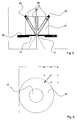
- a laser unit 1 as an energy source.
- the beam This laser is by a in the laser unit. 1 widened integrated widening optics, before moving into a Deflection unit occurs.
- This consists of three rotatable elements 9, 10a and 10b.
- the unit 9, on the units 10a and 10b and the drive unit 3 are attached, via the drive unit 2 and the drive ring 6 is rotated about the axis a.
- the axis a is identical to the optical axis of the laser emitted light beam.
- the unit 9 is under an angle of 45 ° to the axis a of the deflection mirror. 4 attached, the laser beam in the direction b deflects, which is thus perpendicular to the axis a.
- the Axis b which by turning the unit 9 and the axis a can be chosen in any direction is the optical axis of the laser beam between the mirrors 4 and the rotation axis of the units 10a and 10b, when this by the drive unit 3 and the drive rings 7 and 8 are rotated relative to the unit 9.
- the mirror 5 is in the unit 10a in the Basic position at an angle of 45 ° to the axis b arranged and directs the laser beam to the direction from where he leaves the transmitting unit.
- the mirror 5 about two electromechanical actuators 11 and 12, For example, piezo actuators, the mirror 5 to two axes tilted perpendicular to the axis b.
- These Tilting movement has a smaller adjustment range but one shorter positioning time than the rotation about the axes a and b.
- slow movements of the laser beam are reversed large deflection angles due to the rotation around the axes a and b realized; fast but smaller movements by the adjusting elements 11 and 12.
- the rotation angle to the axes a and b can be 360 ° or larger.
- the unit 10th b is also the unit 10th b turned around the axis b.
- the Detector unit consisting for example of a Parabolic mirror 28 and a radiation detector 29, the Recording of the reflected back from the receiver Light installed.
- the synchronous rotation of the units 10a and 10b guarantees that the detector unit always oriented towards the direction under which the Laser beam leaves the transmitter unit.
- Fig. 2 The structure of such a fine actuator on the base a piezocrystal drive is schematically in detail shown in Fig. 2. As you can see, everyone is Mirrors 4 and 5 are pivotally supported about a point A. In this illustration, for the sake of simplicity, only a piezoelectric crystal 9 is shown.
- the piezocrystal is arranged between two lever arms 13,14, wherein the a lever arm 13 deflects the mirror directly while with the other lever 14 via an adjusting device 15 adjusted and biased the entire piezoelectric element can be.
- the entire suspension for both Piezocrystals for a mirror is in its own low distortion housing 16 housed.
- the mobile receiver for example, a one Spacecraft or, as in the case of the one described here Embodiment on a reconnaissance vehicle 17 is located in any Distance from the transmitter, but in the direct Field of view.
- This receiver has, as from the Figures 3 and 4 can be seen, a rotary and adjustable attachment 18, the reception of the laser beam serves.
- the beam receiver 18 is made of a Solar cell surface 19 and a surrounding, the Laser beam to the transmitter back reflecting surface 20 built up.
- the solar cells convert that impinging light of the laser beam into current, the used to power the receiver. Due to the beam profile always a part of the meets Laser beam on the surrounding reflector ring 20, see that of this does not affect the solar cells 19 returning part of the light back to the transmitting unit is reflected.
- the size of the laser beam is like that chosen to be smaller than the diameter of the Solar cell 19 is to ensure that the Main part of the available light energy used for conversion into electrical energy and only a very small proportion is reflected.
- a Aligning unit that ensures that the Beam receiver with its two transverse axes always is normal to the incident beam.
- the heart of this Alignment unit is one behind a small hole 21 in the Center of the solar cells 19 arranged direction sensitive sensor 22, which is shown in detail in FIG. 5 and the off at the ends of jet pipes There are 23 arranged photodiodes 24.
- This Sensor 22 can be measured at any time, whether the Essay 18 still with its two axes perpendicular to Beam is located.
- a deviation is detected is integrated by one in this Control electronics via motors 26 and Drive elements 27 of the attachment 18 in his Orientation readjusted.
- the portion of the reflected back from the receiver Light is in the transmitter unit via a Parabolic mirror 28 collected and over about one central sensor 29 and specific filters in one Information signal regarding the position of the beam converted to the solar surface of the receiver.
- This Signal is in a control unit 30 of the transmitter used to the optimal alignment of the mirror 4 and 5 to adjust and adjust.
- the control computer 30 controls on the basis of collected reflection signal in a cascaded Control both the motors 2 and 3 for the Coarse movement and the piezoelectric crystals 9,10 and 11,12 for the fine motor movements of both mirrors 4 and 5 about their respective pivot point A and governs this way the overall system after.
- a control program that covers the entire procedural Expiration of the automatic energy transfer from one Sending unit to a mobile receiving unit includes, to the device.
- This control program consists essentially of two parts: one Search algorithm that searches and locates the Allows receiver unit in a large area, and a tracking that ensures that a found receiver unit even over long periods precisely tracked and thus constant with energy can be supplied.
- the motor-gear units of the transmitting unit are used to scan the target area over a large area line by line with a weakened laser beam after a return reflex. If such a reflection is detected, the nearer surroundings of the last reflection position are scanned more accurately in a sub-mode and the center circle R m of the reflector ring 20 is independently determined.
- the beam is positioned via the fine control by means of the piezocrystals 9, 10 and 11, 12. This is done in a two-step approach, characterized in that in a first step, a search grid in the form of a 3 by 3 matrix is measured and determines the brightest position and is selected as a new starting point, as shown in Fig. 6. This process is repeated several times.
- a subsequent second step the shape of the ring and thus the central position of the solar surfaces 19 is then detected.
- This algorithm will be illustrated with reference to FIG. From the starting point, several search steps, shown here by way of example at 3 steps, are carried out in a similar direction, in which the reflection signal strength is measured for each individual step. The step direction with the strongest signal value is adopted as the new main analysis direction, and the process is repeated until the contour of the ring reflector is completely detected. On the basis of the individual positions, the center of this surface can now be determined with a center of gravity calculation of the spanned surface, and the transmission beam can thus be guided precisely onto the solar cells 19 in the middle of the ring 20.
- This method is so oriented that, for searching and detecting the solar cells, the receiving unit does not necessarily have to be aligned already normal to the beam direction, but skews are also reliably detected and measured.
- a deterioration is on the Jumped back start position; in an improvement will the new position as a new starting position maintained.
- the procedure will start with a new one Continue step in any direction.
- the Decision whether a change of position to a Improvement or deterioration may have for example, the overall intensity of the backward reflected light, the closer the Position of the laser beam at the center of the solar cell 21 is, the less light hits the reflector ring 20 and is reflected or she may, for example by the "modulation method" i. through the Detection of the double frequency can be determined, so as described below as a separate method is.
- the designated procedure becomes the current position set the laser beam as the center.
- the beam is positioned in each vector direction and the Signal strength determined at each endpoint.
- a new vector that is strongest in the direction Intensity shows and its amount a measure of the Distance of offset is. On the basis of this vector will the new center determines.
- the procedure can be still optimize by after every single measurement already a correction step from new and old Vectors is determined. Increased by this optimization
- the responsiveness of the system to others make directional changes smoother because it is already slightly corrected after each measurement and not only after a full cycle.
- the so-called “circle process” is in the beam direction in the second mirror 5 in horizontal direction a modulation of the frequency f and a modulation thereof in the vertical direction Frequency but out of phase by 90 degrees.
- the mirror 5 performs circular movements and the laser beam becomes the center in this way modulated.
- the reflection signal then describes over the direction a sinusoidal contour, as in FIG. 9 illustrated. The bigger the amplitude, the better Further, the beam is away from the center on the reflection foil.
- the individual phases Assign directions and it will be in the direction weakest intensity regulates to the center of To be solar surfaces.
- FIG. 11 shows the reflected light intensity as a function of the position of the laser beam on the receiver. If x M is exactly the one in the center of the photocell 19 and x 0 smaller than the radius of the photocell, then portions of the laser beam hit the reflector ring 20 both right and left in one oscillation pass.
- the back-reflected light is modulated at twice the frequency 2 f.
- a lock-in amplifier or a Fourier analysis can be used for a control loop.
- the modulation method is not limited to one dimension.
- the mirror 5 can be modulated, for example, in the horizontal as well as in the vertical direction with two different frequencies f 1 and f 2 .
- both frequencies are chosen clearly different and in a non-rational relationship to one another in order to be able to accurately recognize in the frequency analysis of the reflected-back light in which way the position of the laser beam deviates from the center of the solar cell.
Abstract
Description
Die Erfindung betrifft ein Verfahren und eine Vorrichtung zur Energieübertragung mittels kohärenter elektromagnetischer Strahlung unter Verwendung eines Senders und eines EmpfängersThe invention relates to a method and a Device for energy transmission by means of coherent electromagnetic radiation using a Transmitter and a receiver
Verfahren und Vorrichtungen dieser Art, die ohne direkten mechanischen und/oder elektrischen Kontakt arbeiten, sind bereits bekannt und finden praktisch ausschließlich zur Energieübertragung über kurze Distanzen und für kleine Energiemengen Verwendung.Methods and devices of this kind, without direct mechanical and / or electrical contact work, are already known and find practical exclusively for energy transfer via short Distances and for small amounts of energy use.
Aufgabe der Erfindung ist es, ein Verfahren der eingangs genannten Art so auszubilden, daß es auf einfache Weise eine drahtlose Energieübertragung zur automatischen Versorgung einer weit entfernten mobilen Einheit mit Energie auch über große Distanzen ermöglicht und das zugleich einfach, sicher und flexibel einsetzbar ist. Ferner soll durch die Erfindung eine Vorrichtung zur Durchführung eines solchen Verfahrens bereitgestellt werden. The object of the invention is to provide a method of the aforementioned type so that it on easy way to wireless energy transfer to automatic supply of a distant mobile Unit with energy even over long distances and at the same time simple, safe and secure is flexible. Furthermore, should by the Invention an apparatus for performing a be provided such method.
Die Erfindung löst die erste Aufgabe, indem sie bei einem derartigen Verfahren vorsieht, daß von einer Sendeeinheit ein gerichteter, geregelter Laserstrahl auf den Empfänger gesandt und von diesem ein Teil der einfallenden Strahlung zur Sendeeinheit zurück reflektiert wird und daß aus dem reflektierten Strahl Informationen für eine Ausrichtung der Sendeeinheit abgeleitet und an eine mit einer Ausrichteinheit für die Sendeeinheit verbundene Regelungseinheit übermittelt werden. Bei der zur Lösung der weiteren Aufgabe vorgesehenen Vorrichtung weist die Sendeeinheit über eine Steuerungseinheit sowie Stelleinrichtungen ansteuerbare Spiegel zur Ablenkung des Strahles auf und die Empfangseinheit weist einen eine Photozellenanordnung ringförmig umgebenden Retroreflektor auf.The invention solves the first task by at Such a method provides that of a Sending unit a directed, regulated laser beam sent to the recipient and from this part of the incident radiation back to the transmitting unit is reflected and that from the reflected beam Information for an orientation of the transmitting unit derived and connected to one with an alignment unit for the transmission unit connected control unit be transmitted. When to solve the other Task provided device has the transmitting unit via a control unit and adjusting devices controllable mirror for deflecting the beam on and the receiving unit has a Photocell array surrounding annular Retroreflector on.
In vorteilhafter Weiterbildung der Erfindung ist am Empfänger eine automatische Ausrichteinheit vorgesehen, um das Energieempfangsfeld optimal auf den eintreffenden Energiestrahl auszurichten.In an advantageous embodiment of the invention is on Receiver provided an automatic alignment unit, around the energy receiving field optimally on the Align incoming energy beam.
Durch die in vorteilhafter Weiterbildung der Erfindung vorgesehene Modulation des Laserstrahls wird die Bewegung des Empfängers analysiert und der Strahl wird über die Transmittervorrichtung nachgeführt. Die erfindungsgemäß vorgesehene Regelung, die auf einer Messung der Intensität der reflektierten Strahlung basiert, ermöglicht damit das Folgen des Strahls bei einer Bewegung des Empfängers sowohl in horizontaler als auch in vertikaler Richtung.By in an advantageous embodiment of the invention intended modulation of the laser beam is the Movement of the receiver is analyzed and the beam becomes Tracked via the transmitter device. The According to the invention provided on a control Measurement of the intensity of the reflected radiation based, thus enabling following the beam at a movement of the recipient in both horizontal as well as in the vertical direction.
Nachfolgend soll die Erfindung anhand von in der Zeichnung dargestellten Ausführungsbeispielen näher erläutert werden. Es zeigen
- Fig. 1
- den Aufbau einer Sendeeinheit,
- Fig. 2
- ein Detail der Anordnung gemäß Fig. 1,
- Fig. 3
- eine schematische Darstellung eines Empfängers in Vorderansicht,
- Fig. 4
- eine rückwärtige Ansicht des Empfänger gemäß Fig. 3,
- Fig. 5
- eine schematische Darstellung eines Nachstellmechanismus der Anordnung gemäß Fig. 3 und 4,
- Fig. 6
- eine schematische Darstellung der Vorgehensweise zum Auffinden eines Reflektors,
- Fig. 7
- eine schematische Darstellung des Vorgangs zum Erfassen des Reflektorringes,
- Fig. 8
- eine schematische Darstellung eine Methode zur Nachführung des Laserstrahls,
- Fig. 9:
- eine schematische Darstellung einer weiteren Nachführmethode,
- Fig. 10
- das Auftreten der fundamentalen und der ersten Harmonischen der Modulationsfrequenz in Abhängigkeit von der räumlichen Verstimmung
- Fig. 1
- the construction of a transmitting unit,
- Fig. 2
- a detail of the arrangement of FIG. 1,
- Fig. 3
- a schematic representation of a receiver in front view,
- Fig. 4
- a rear view of the receiver of FIG. 3,
- Fig. 5
- 1 is a schematic representation of an adjusting mechanism of the arrangement according to FIGS. 3 and 4,
- Fig. 6
- a schematic representation of the procedure for finding a reflector,
- Fig. 7
- a schematic representation of the process for detecting the reflector ring,
- Fig. 8
- a schematic representation of a method for tracking the laser beam,
- Fig. 9:
- a schematic representation of another tracking method,
- Fig. 10
- the occurrence of the fundamental and the first harmonic of the modulation frequency as a function of the spatial detuning
Bei der in den Figuren dargestellten Vorrichtung dient
eine Lasereinheit 1 als Energiequelle. Der Strahl
dieses Lasers wird durch eine in die Lasereinheit 1
integrierte Aufweitoptik verbreitert, bevor er in eine
Ablenkeinheit eintritt. Diese besteht aus drei
drehbaren Elementen 9, 10a und 10b. Die Einheit 9, an
der die Einheiten 10a und 10b sowie die Antriebseinheit
3 befestigt sind, wird über die Antriebseinheit 2 und
den Antriebsring 6 um die Achse a gedreht. Die Achse a
ist identisch mit der optischen Achse des aus dem Laser
emittierten Lichtstrahles. In der Einheit 9 ist unter
einem Winkel von 45° zur Achse a der Ablenkspiegel 4
befestigt, der den Laserstrahl in die Richtung b
ablenkt, die somit senkrecht zur Achse a steht. Die
Achse b, die durch Drehen der Einheit 9 und die Achse a
in beliebiger Richtung gewählt werden kann, ist die
optische Achse des Laserstrahls zwischen den Spiegeln 4
und die Rotationsachse der Einheiten 10a und 10b, wenn
diese durch die Antriebseinheit 3 und die Antriebsringe
7 und 8 relativ gegenüber der Einheit 9 gedreht werden.In the device shown in the figures is used
a
Der Spiegel 5 ist in der Einheit 10a in der
Grundstellung in einem Winkel von 45° zur Achse b
angeordnet und lenkt den Laserstrahl auf die Richtung
ab unter der er die Sendeeinheit verlässt. Über zwei
elektromechanische Stellelemente 11 und 12,
beispielsweise Piezo-Aktoren, wird der Spiegel 5 um
zwei Achsen senkrecht zur Achse b gekippt. Diese
Kippbewegung hat einen kleineren Stellbereich aber eine
kürzere Stellzeit als die Drehung um die Achsen a und
b. Somit werden langsame Bewegungen des Laserstrahls um
große Ablenkwinkel durch die Drehung um die Achsen a
und b realisiert; schnelle aber kleinere Bewegungen
durch die Stellelemente 11 und 12. Die Drehwinkel um
die Achsen a bzw. b können 360° oder größer sein.
Synchron mit der Einheit 10 a wird auch die Einheit 10
b um die Achse b gedreht. An der Einheit 10 b ist die
Detektoreinheit, bestehend beispielsweise aus einem
Parabolspiegel 28 und einem Strahlungsdetektor 29, zur
Aufnahme des von dem Empfänger rückreflektierten
Lichtes installiert. Das synchrone Drehen der Einheiten
10a und 10b garantiert, dass die Detektoreinheit stets
auf die Richtung ausgerichtet ist unter der der
Laserstrahl die Sendeeinheit verlässt. The
Der Aufbau eines solchen Feinstellgliedes auf der Basis
eines Piezokristallantriebes ist schematisch im Detail
in Fig. 2 dargestellt. Wie ersichtlich, ist jeder der
Spiegel 4 bzw. 5 um einen Punkt A schwenkbar gehaltert.
In dieser Darstellung ist der Einfachheit halber nur
ein Piezokristall 9 gezeigt. Der Piezokristall ist
zwischen zwei Hebelarmen 13,14 angeordnet, bei der der
eine Hebelarm 13 den Spiegel direkt auslenkt, während
mit dem anderen Hebel 14 über eine Justiereinrichtung
15 das gesamte Piezoelement justiert und vorgespannt
werden kann. Die gesamte Aufhängung für beide
Piezokristalle für einen Spiegel ist in einem eigenen
verzerrungsarmen Gehäuse 16 untergebracht.The structure of such a fine actuator on the base
a piezocrystal drive is schematically in detail
shown in Fig. 2. As you can see, everyone is
Der mobile Empfänger, der beispielsweise ein einem
Raumfahrzeug oder, wie im Fall des hier beschriebenen
Ausführungsbeispiels auf einem Erkundungsfahrzeug 17
angeordnet ist, befindet sich in einer beliebigen
Entfernung vom Sender, jedoch in dessen direktem
Sichtfeld. Dieser Empfänger besitzt, wie aus den
Figuren 3 und 4 ersichtlich ist, einen dreh- und
regelbaren Aufsatz 18, der dem Empfang des Laserstrahls
dient. Der Strahlempfänger 18 ist aus einer
Solarzellenfläche 19 und einer diese umgebenden, den
Laserstrahl zum Sender zurück reflektierenden Fläche 20
aufgebaut. Dabei wandeln die Solarzellen das
auftreffende Licht des Laserstrahles in Strom um, der
zur Energieversorgung des Empfängers genutzt wird.
Aufgrund des Strahlprofils trifft stets ein Teil des
Laserstrahles auf den umgebenden Reflektorring 20, so
daß von diesem der nicht auf die Solarzellen 19
treffende Teil des Lichtes zur Sendeeinheit zurück
reflektiert wird. Die Größe des Laserstrahls ist so
gewählt, daß sie kleiner als der Durchmesser der
Solarzelle 19 ist, um sicherzustellen, daß der
Hauptanteil der zur Verfügung stehenden Lichtenergie
für die Umwandlung in elektrische Energie genutzt wird
und nur ein sehr geringer Anteil reflektiert wird.The mobile receiver, for example, a one
Spacecraft or, as in the case of the one described here
Embodiment on a
Weiterhin ist bei dem hier beschriebenen
Ausführungsbeispiel und wie in den Figuren 4 und 5
dargestellt, in den Strahlempfänger 18 eine
Ausrichteinheit integriert, die sicherstellt, daß der
Strahlempfänger mit seinen beiden Querachsen stets
normal zum einfallenden Strahl steht. Herzstück dieser
Ausrichteinheit ist ein hinter einem kleinen Loch 21 im
Zentrum der Solarzellen 19 angeordneter
richtungsempfindlicher Sensor 22, der im Detail in Fig.
5 gezeigt ist und der aus an den Enden von Strahlrohren
23 angeordneten Photodioden 24 besteht. Mittels dieses
Sensors 22 kann jederzeit gemessen werden, ob sich der
Aufsatz 18 noch mit seinen beiden Achsen senkrecht zum
Strahl befindet. Sobald in einer nachgeschalteten
Auswerteeinheit 25 eine Abweichung festgestellt wird,
wird von einer in diese integrierten
Steuerungselektronik über Motoren 26 und
Antriebselemente 27 der Aufsatz 18 in seiner
Orientierung nachgeregelt.Furthermore, in the case described here
Embodiment and as in Figures 4 and 5
shown in the beam receiver 18 a
Aligning unit that ensures that the
Beam receiver with its two transverse axes always
is normal to the incident beam. The heart of this
Alignment unit is one behind a
Der vom Empfänger zurück reflektierte Anteil des
Lichtes wird in der Sendereinheit über einen
Parabolspiegel 28 aufgefangen und über über einen
zentralen Sensor 29 und spezifische Filter in ein
Informationssignal bezüglich der Position des Strahles
auf der Solarfläche des Empfängers umgewandelt. Dieses
Signal wird in einer Steuerungseinheit 30 des Senders
dazu verwendet, die optimale Ausrichtung der Spiegel 4
und 5 einzustellen und nachzuregeln. The portion of the reflected back from the receiver
Light is in the transmitter unit via a
Parabolic mirror 28 collected and over about one
central sensor 29 and specific filters in one
Information signal regarding the position of the beam
converted to the solar surface of the receiver. This
Signal is in a control unit 30 of the transmitter
used to the optimal alignment of the
Der Steuercomputer 30 steuert dabei auf der Basis des
aufgefangenen Reflektionssignals in einer kaskadierten
Regelung sowohl die Motoren 2 und 3 für die
Grobbewegung als auch die Piezokristalle 9,10 und 11,12
für die feinmotorischen Bewegungen beider Spiegel 4 und
5 um ihren jeweiligen Drehpunkt A an und regelt auf
diese Weise das Gesamtsystem nach.The control computer 30 controls on the basis of
collected reflection signal in a cascaded
Control both the
Neben den Sende- und Empfangseinheiten gehört weiterhin ein Steuerprogramm, das den gesamten prozeduralen Ablauf der automatischen Energieübertragung von einer Sendeeinheit zu einer mobilen Empfangseinheit beinhaltet, zur Vorrichtung. Dieses Steuerungsprogramm besteht im wesentlichen aus zwei Teilen: Einem Suchalgorithmus, der das Suchen und Auffinden der Empfängereinheit in einem großen Bereich ermöglicht, und einer Nachführung, die dafür sorgt, daß eine gefundene Empfängereinheit auch über längere Zeiträume genau nachgeführt und damit konstant mit Energie versorgt werden kann.In addition to the transmitting and receiving units heard a control program that covers the entire procedural Expiration of the automatic energy transfer from one Sending unit to a mobile receiving unit includes, to the device. This control program consists essentially of two parts: one Search algorithm that searches and locates the Allows receiver unit in a large area, and a tracking that ensures that a found receiver unit even over long periods precisely tracked and thus constant with energy can be supplied.
Im Suchmodus werden anfangs die Motor-Getriebeeinheiten
der Sendeeinheit dazu verwendet, mit einem
abgeschwächten Laserstrahl den Zielbereich großflächig
zeilenweise nach einem Rückreflex abzuscannen. Wird
eine solche Reflexion erfaßt, so wird in einem Submodus
die nähere Umgebung der letzten Reflektionsposition
genauer gescannt und dabei selbständig der Mittelkreis
Rm des Reflektorringes 20 ermittelt. Hierbei wird der
Strahl über die Feinsteuerung mittels der
Piezokristalle 9,10 und 11,12 positioniert. Dies
geschieht in einem zweistufigen Vorgehen dadurch, daß
in einem ersten Schritt ein Suchraster in Form einer 3
mal 3 Matrix vermessen wird und dabei die lichtstärkste
Position bestimmt und als neuer Startpunkt gewählt
wird, wie dies in Fig. 6 veranschaulicht ist. Dieser
Vorgang wird mehrmals wiederholt. In einem
nachfolgenden zweiten Schritt wird dann die Form des
Ringes und damit die Zentralposition der Solarflächen
19 erfaßt. Dieser Algorithmus wird anhand von Fig. 7
veranschaulicht. Vom Ausgangspunkt werden mehrere
Suchschritte, hier an 3 Schritten exemplarisch gezeigt,
in eine ähnliche Richtung durchgeführt, bei denen für
jeden einzelnen Schritt die Reflektionssignalstärke
gemessen wird. Die Schrittrichtung mit dem stärksten
Signalwert wird als neue Hauptanalyserichtung
angenommen, und der Vorgang so oft wiederholt, bis die
Kontur des Ringreflektors komplett erfaßt ist. Auf der
Basis der Einzelpositionen kann nun mit einer
Schwerpunktsberechnung der aufgespannten Fläche das
Zentrum dieser Fläche bestimmt werden und der
Sendestrahl damit genau auf die Solarzellen 19 in der
Mitte des Ringes 20 geführt werden. Dieses Verfahren
ist so ausgerichtet, dass zum Suchen und Erfassen der
Solarzellen die Empfangseinheit nicht notwendigerweise
bereits normal zur Strahlrichtung ausgerichtet sein
muß, sondern auch Schräglagen sicher detektiert und
vermessen werden.In the search mode, initially the motor-gear units of the transmitting unit are used to scan the target area over a large area line by line with a weakened laser beam after a return reflex. If such a reflection is detected, the nearer surroundings of the last reflection position are scanned more accurately in a sub-mode and the center circle R m of the
Zur sicheren Nachführung des Sendestrahles auf die gefundene und vermessene Empfangseinheit sind alternativ vier verschiedene Grundalgorithmen vorgesehen, die nachfolgend näher beschrieben werden sollen.For safe tracking of the transmission beam on the found and measured receiving unit are alternatively four different basic algorithms provided, which are described in more detail below should.
Bei dem ersten Verfahren, das auch als "Random Walk"
bezeichnet wird, wird die Position der Laserstrahls von
der Startposition aus um einen kleinen Schritt in eine
beliebige Richtung verändert und mittels des vom
Empfänger rückreflektierten Lichtes bestimmt, ob dieser
Schritt eine Verbesserung oder Verschlechterung
darstellte. Bei einer Verschlechterung wird auf die
Startposition zurückgesprungen; bei einer Verbesserung
wird die neue Position als neue Startposition
beibehalten. Danach wird die Prozedur mit einem neuen
Schritt in eine beliebige Richtung fortgesetzt. Die
Entscheidung ob ein Positionswechsel zu einer
Verbesserung oder Verschlechterung geführt hat, kann
beispielsweise über die Gesamtintensität des
rückreflektierten Lichtes bestimmt werden, je näher der
Position des Laserstrahls an der Mitte der Solarzelle
21 ist, umso weniger Licht trifft auf den Reflektorring
20 und wird reflektiert oder sie kann beispielsweise
durch das "Modulationsverfahren" d.h. durch die
Detektion der doppelten Frequenz bestimmt werden, so
wie es weiter hinten als eigene Methode beschrieben
ist.In the first procedure, also called "Random Walk"
is designated, the position of the laser beam of
the starting position by a small step in one
any direction changed and by means of the
Receiver of reflected light determines if this
Step an improvement or deterioration
showed. At a deterioration is on the
Jumped back start position; in an improvement
will the new position as a new starting position
maintained. After that, the procedure will start with a new one
Continue step in any direction. The
Decision whether a change of position to a
Improvement or deterioration may have
for example, the overall intensity of the
backward reflected light, the closer the
Position of the laser beam at the center of the
Bei der zweiten, als "Schwerpunkt-Verfahren" bezeichneten Vorgehensweise wird die momentane Position des Laserstrahls als Mittelpunkt festgelegt. Nun werden mindestens drei Vektoren gleicher Länge, jedoch verschiedener Richtungen gewählt. Die Richtungen sind vorzugsweise so gewählt, daß sie achsensymmetrisch zur horizontalen und vertikalen Achse sind, wie dies in Fig. 8 für 4 Vektoren veranschaulicht ist. Dann wird der Strahl in jede Vektorrichtung positioniert und die Signalstärke an jedem Endpunkt bestimmt. Nachdem jede Position einmal gemessen wurde, werden über eine Schwerpunktberechnung die Vektoren mit ihrer Signalstärke zueinander gewichtet. Als Ergebnis ergibt sich ein neuer Vektor, der in die Richtung stärkster Intensität zeigt und dessen Betrag ein Maß für den Abstand des Versatzes ist. Anhand dieses Vektors wird der neue Mittelpunkt bestimmt. Das Verfahren läßt sich noch optimieren, indem nach jeder einzelnen Messung bereits ein Korrekturschritt aus neuen und alten Vektoren bestimmt wird. Durch diese Optimierung erhöht sich zum einen die Reaktionsfähigkeit des Systems zum anderen werden Richtungsänderungen glatter gestaltet, da bereits nach jeder Messung leicht korrigiert wird und nicht erst nach einem vollem Zyklus.At the second, as a "focus method" The designated procedure becomes the current position set the laser beam as the center. Well be at least three vectors of equal length, however chosen in different directions. The directions are preferably chosen so that they are axisymmetric to horizontal and vertical axis are as in Fig. 8 is illustrated for 4 vectors. Then it will be the beam is positioned in each vector direction and the Signal strength determined at each endpoint. After each Once the position has been measured, you will have one Focusing the vectors with their Signal strength to each other weighted. As a result, results yourself a new vector that is strongest in the direction Intensity shows and its amount a measure of the Distance of offset is. On the basis of this vector will the new center determines. The procedure can be still optimize by after every single measurement already a correction step from new and old Vectors is determined. Increased by this optimization On the one hand, the responsiveness of the system to others make directional changes smoother because it is already slightly corrected after each measurement and not only after a full cycle.
Beim dritten, dem sogenannten "Kreis-Verfahren", wird
auf den in Strahlrichtung zweiten Spiegel 5 in
horizontaler Richtung eine Modulation der Frequenz f
und in vertikaler Richtung eine Modulation derselben
Frequenz, aber um 90 Grad phasenverschoben, geprägt.
Dadurch führt der Spiegel 5 Kreisbewegungen durch und
der Laserstrahl wird auf diese Weise um den Mittelpunkt
moduliert. Durch Messung der Referenzspannung an den
Piezokristallen ist es möglich, zu ermitteln, in
welchem Winkel der Spiegel 5 gerade steht. Jetzt wird
genau ein Kreisdurchgang lang kontinuierlich gemessen.
Das Reflektionssignal beschreibt dann über der Richtung
eine sinusförmige Kontur, wie in Fig. 9
veranschaulicht. Je größer die Amplitude ist, desto
weiter befindet sich der Strahl von der Mitte entfernt
auf der Reflektionsfolie. Durch einen Vergleich mit dem
Referenzsignal ist es so möglich, den einzelnen Phasen
Richtungen zuzuordnen und es wird in die Richtung
schwächster Intensität regelt, um im Zentrum der
Solarflächen zu sein.In the third, the so-called "circle process" is
in the beam direction in the
Beim vierten, dem so genannten "Modulations-Verfahren"
wird die Position x des Laserstrahls um seine
Mittenposition xM in Abhängigkeit von der Zeit t mit
einer Modulationsfrequenz f gemäß x = xM + x0 sin(2 n f
t) moduliert. Da, wie in Fig. 10 dargestellt, stets ein
Teil der Laserstrahles auf den Reflexionsring 20
trifft, wird das rückreflektierte Licht mit der
Frequenz f und deren höheren Harmonischen moduliert
sein. Die Figur 11 zeigt die rückreflektierte
Lichtintensität in Abhängigkeit der Position des
Laserstrahls auf dem Empfänger. Ist xM genau der in
Mitte der Photozelle 19 und x0 kleiner als der Radius
der Photozelle, so treffen Teilbereiche des
Laserstrahls bei einem Schwingungsdurchgang sowohl
rechts wie links auf den Reflektorring 20. Das
rückreflektierte Licht ist mit der doppelten Frequenz 2
f moduliert. Je weiter xM von der Mitte der Photozelle
entfernt ist, umso geringer wird die Komponente bei 2f,
denn auf einer Seite wird der Reflektorring 20 immer
weniger getroffen. Ist xM genau auf dem Rand der
Photozelle 20, so wird bei einem Schwingungsvorgang in
der halben Zeit die Photozelle 19 und in der anderen
halben Zeit der Reflektorring 20 überstrichen; das
rückreflektierte ist jetzt nur mit der Frequenz f
moduliert und hat so gut wie keine Komponenten bei der
Frequenz 2 f. Sollte der Laserstrahl auf den
Mittenradius des Reflektorrings 20 (rM in Figur 6)
gerutscht sein, so tritt im rückreflektierten Licht
wieder eine starke Komponente bei der Frequenz 2 f auf;
diese Komponente ist aber gegenüber der Position "xM in
der Mitte der Photozelle" um 180° phasenverschoben, da
der Lichtstrahl bei den Umkehrpunkten der Schwingung
auf gering reflektierende Strukturen trifft.In the fourth, the so-called "modulation method", the position x of the laser beam about its center position x M is modulated as a function of the time t with a modulation frequency f according to x = x M + x 0 sin (2 nf t). Since, as shown in Fig. 10, always a part of the laser beam is incident on the
Somit ist aus der Größe und der Phase der Komponente
bei Frequenz 2 f abzuleiten, wie gut die Position des
Laserstrahls xM mit der Mitte der Photozelle 20
übereinstimmt. Für einen Regelkreis kann beispielsweise
ein Lock-In-Verstärker oder eine Fourier-Analyse
herangezogen werden. Thus, it can be deduced from the size and the phase of the component at frequency 2 f how well the position of the laser beam x M coincides with the center of the
Das Modulationsverfahren ist nicht auf eine Dimension
beschränkt. Der Spiegel 5 kann beispielsweise in
horizontaler sowie in vertikaler Richtung mit zwei
unterschiedlichen Frequenzen f1 und f2 moduliert
werden. Vorzugweise werden beide Frequenzen deutlich
unterschiedlich und in einem nicht rationalen
Verhältnis zueinander gewählt, um in der
Frequenzanalyse des rückreflektierten Lichtes genau
erkennen zu können, in welcher Weise die Position des
Laserstrahls von der Mitte der Solarzelle abweicht.The modulation method is not limited to one dimension. The
Auf diese Weise wird bei jedem der vorangehend beschriebenen Verfahren eine optimale Ausrichtung der Anordnung erzielt, die zugleich einen maximalen Energieübertrag gewährleistet.In this way, in each of the preceding described optimum alignment of the Arrangement achieved at the same time a maximum Energy transfer guaranteed.
Claims (15)
Applications Claiming Priority (2)
| Application Number | Priority Date | Filing Date | Title |
|---|---|---|---|
| DE102004008681A DE102004008681A1 (en) | 2004-02-21 | 2004-02-21 | Method for energy transmission by means of coherent electromagnetic radiation |
| DE102004008681 | 2004-02-21 |
Publications (2)
| Publication Number | Publication Date |
|---|---|
| EP1566902A1 true EP1566902A1 (en) | 2005-08-24 |
| EP1566902B1 EP1566902B1 (en) | 2006-12-27 |
Family
ID=34706889
Family Applications (1)
| Application Number | Title | Priority Date | Filing Date |
|---|---|---|---|
| EP05000093A Not-in-force EP1566902B1 (en) | 2004-02-21 | 2005-01-05 | Method of energy transmission using coherent electromagnetic radiation |
Country Status (5)
| Country | Link |
|---|---|
| US (1) | US7423767B2 (en) |
| EP (1) | EP1566902B1 (en) |
| JP (1) | JP4538339B2 (en) |
| AT (1) | ATE349819T1 (en) |
| DE (2) | DE102004008681A1 (en) |
Cited By (3)
| Publication number | Priority date | Publication date | Assignee | Title |
|---|---|---|---|---|
| WO2007038023A1 (en) * | 2005-09-28 | 2007-04-05 | Motorola Inc. | Light pad charger for electronic devices |
| WO2014086330A3 (en) * | 2012-12-05 | 2014-11-27 | Eads Deutschland Gmbh | Wireless remote energy supply for unmanned aerial vehicles |
| EP4228122A4 (en) * | 2020-11-02 | 2024-04-10 | Huawei Tech Co Ltd | Laser emitting apparatus, laser emitting method and laser wireless charging system |
Families Citing this family (40)
| Publication number | Priority date | Publication date | Assignee | Title |
|---|---|---|---|---|
| US8182473B2 (en) | 1999-01-08 | 2012-05-22 | Palomar Medical Technologies | Cooling system for a photocosmetic device |
| US6517532B1 (en) | 1997-05-15 | 2003-02-11 | Palomar Medical Technologies, Inc. | Light energy delivery head |
| DK0991372T3 (en) * | 1997-05-15 | 2004-12-06 | Palomar Medical Tech Inc | Apparatus for dermatological treatment |
| BR0312430A (en) | 2002-06-19 | 2005-04-26 | Palomar Medical Tech Inc | Method and apparatus for treating skin and subcutaneous conditions |
| US20070019693A1 (en) * | 2005-03-07 | 2007-01-25 | Graham David S | Wireless power beaming to common electronic devices |
| US7856985B2 (en) | 2005-04-22 | 2010-12-28 | Cynosure, Inc. | Method of treatment body tissue using a non-uniform laser beam |
| AU2006292526A1 (en) | 2005-09-15 | 2007-03-29 | Palomar Medical Technologies, Inc. | Skin optical characterization device |
| FR2899692B1 (en) | 2006-04-06 | 2008-10-17 | Hitpool Systems Entpr Uniperso | LOCATION AND POSITIONING SYSTEM FOR GUIDING A MOBILE ENTITY IN RELATION TO ONE OR MORE OTHER OBJECTS |
| US7586957B2 (en) | 2006-08-02 | 2009-09-08 | Cynosure, Inc | Picosecond laser apparatus and methods for its operation and use |
| US20080084596A1 (en) * | 2006-10-06 | 2008-04-10 | Powerbeam, Inc. | Active Mirror for Power Beaming |
| EP2089942A4 (en) * | 2006-11-21 | 2011-04-27 | Powerbeam Inc | Optical power beaming to electrically powered devices |
| US7711441B2 (en) * | 2007-05-03 | 2010-05-04 | The Boeing Company | Aiming feedback control for multiple energy beams |
| US8525097B2 (en) * | 2008-01-03 | 2013-09-03 | Wi-Charge Ltd. | Wireless laser system for power transmission utilizing a gain medium between retroreflectors |
| US9919168B2 (en) | 2009-07-23 | 2018-03-20 | Palomar Medical Technologies, Inc. | Method for improvement of cellulite appearance |
| IL200904A (en) * | 2009-09-13 | 2015-07-30 | Yefim Kereth | Device for object detection and location |
| US10148131B2 (en) * | 2011-05-27 | 2018-12-04 | uBeam Inc. | Power density control for wireless power transfer |
| US9214151B2 (en) | 2011-05-27 | 2015-12-15 | uBeam Inc. | Receiver controller for wireless power transfer |
| US9819399B2 (en) | 2011-05-27 | 2017-11-14 | uBeam Inc. | Beam interaction control for wireless power transfer |
| US9831920B2 (en) | 2011-05-27 | 2017-11-28 | uBeam Inc. | Motion prediction for wireless power transfer |
| US9800091B2 (en) * | 2011-06-09 | 2017-10-24 | Lasermotive, Inc. | Aerial platform powered via an optical transmission element |
| EP2839552A4 (en) | 2012-04-18 | 2015-12-30 | Cynosure Inc | Picosecond laser apparatus and methods for treating target tissues with same |
| JP5929563B2 (en) * | 2012-07-03 | 2016-06-08 | 三菱電機株式会社 | Wireless power feeding system, power transmitting device and power receiving device |
| US10285757B2 (en) | 2013-03-15 | 2019-05-14 | Cynosure, Llc | Picosecond optical radiation systems and methods of use |
| US9991048B2 (en) * | 2014-06-24 | 2018-06-05 | The Board Of Trustees Of The University Of Alabama | Wireless power transfer systems and methods |
| US10734943B2 (en) * | 2014-09-12 | 2020-08-04 | The Government Of The United States Of America, As Represented By The Secretary Of The Navy | Photovoltaics optimized for laser remote power applications at eye-safer wavelengths |
| JPWO2017056469A1 (en) * | 2015-09-29 | 2018-07-12 | パナソニックIpマネジメント株式会社 | Light source device and light projecting device |
| WO2017205549A2 (en) | 2016-05-24 | 2017-11-30 | California Institute Of Technology | Laser wireless power transfer system with active and passive safety measures |
| CN106451666B (en) * | 2016-11-21 | 2019-05-14 | 宇龙计算机通信科技(深圳)有限公司 | The device and method of millimeter electric wave wireless charging |
| TW201823673A (en) * | 2016-12-28 | 2018-07-01 | 鴻海精密工業股份有限公司 | Laser distance measuring device |
| EP3701646A2 (en) | 2017-10-23 | 2020-09-02 | Felicelli, Antoine | Energy transfer device, energy harvesting device, and power beaming system |
| JP7208654B2 (en) | 2018-02-23 | 2023-01-19 | ファイオン・テクノロジーズ・コーポレイション | Method for safe and secure free-space power and data transmission |
| WO2019165426A1 (en) | 2018-02-26 | 2019-08-29 | Cynosure, Inc. | Q-switched cavity dumped sub-nanosecond laser |
| WO2020122907A1 (en) * | 2018-12-12 | 2020-06-18 | Hewlett-Packard Development Company, L.P. | Receivers and transmitters for wireless charging of devices in motion |
| GB201914045D0 (en) | 2019-09-30 | 2019-11-13 | Sintef Tto As | Wireless charging of devices |
| US20240055903A1 (en) * | 2019-10-04 | 2024-02-15 | Wi-Charge Ltd. | Two-way secure interface for an optical wireless power system |
| CN111123250B (en) * | 2019-12-30 | 2021-09-28 | 成都汇蓉国科微系统技术有限公司 | Pulse Doppler radar based on pattern search algorithm and beam forming method |
| US20220196563A1 (en) * | 2020-12-17 | 2022-06-23 | The Boeing Company | Laser bond inspection system and method |
| IL286842A (en) * | 2021-09-30 | 2023-04-01 | Wi Charge Ltd | A system for location and charging of wireless power receivers |
| IL287976A (en) * | 2021-11-09 | 2023-06-01 | Wi Charge Ltd | Scanning mirror for laser power transmission system |
| US11831401B1 (en) * | 2023-03-24 | 2023-11-28 | Wireless Photonics Llc | Communication system and method for ultra-flexible and ultra-reliable laser beam based wireless communication |
Citations (6)
| Publication number | Priority date | Publication date | Assignee | Title |
|---|---|---|---|---|
| US3942894A (en) * | 1974-11-20 | 1976-03-09 | The United States Of America As Represented By The Secretary Of The Air Force | Self referencing retransmitting alignment sensor for a collimated light beam |
| US5142400A (en) * | 1989-12-26 | 1992-08-25 | Cubic Corporation | Method and apparatus for automatic acquisition and alignment of an optical beam communication link |
| US5260639A (en) * | 1992-01-06 | 1993-11-09 | The United States Of America As Represented By The Administrator Of The National Aeronautics And Space Administration | Method for remotely powering a device such as a lunar rover |
| EP1191715A2 (en) * | 2000-09-20 | 2002-03-27 | Texas Instruments Inc. | Optical wireless network with direct optical beam pointing |
| US6407535B1 (en) * | 2000-09-08 | 2002-06-18 | The Regents Of The University Of California | System for beaming power from earth to a high altitude platform |
| US6534705B2 (en) * | 2000-10-23 | 2003-03-18 | Power Beaming Corporation | Methods and apparatus for beaming power |
Family Cites Families (13)
| Publication number | Priority date | Publication date | Assignee | Title |
|---|---|---|---|---|
| AT301331B (en) * | 1968-11-25 | 1972-08-25 | Eumig | Device for distance measurement |
| GB1269892A (en) * | 1969-03-20 | 1972-04-06 | Messerschmitt Boelkow Blohm | Weapon system for the detection of and use against stationary or moving objects |
| US4836672A (en) * | 1980-05-02 | 1989-06-06 | Riverside Research Institute | Covert optical system for probing and inhibiting remote targets |
| DE3342403A1 (en) * | 1983-11-24 | 1985-07-18 | Fraunhofer-Gesellschaft zur Förderung der angewandten Forschung e.V., 8000 München | Sensor arrangement for detecting the position of objects, in particular the rotary angular position of parts which can rotate about an axis |
| US4836673A (en) * | 1986-12-24 | 1989-06-06 | The Dow Chemical Company | Wavelength accuracy test solution and method |
| FR2677516B1 (en) * | 1991-06-04 | 1994-12-09 | Europ Agence Spatiale | OPTICAL COMMUNICATIONS TERMINAL. |
| US5200606A (en) * | 1991-07-02 | 1993-04-06 | Ltv Missiles And Electronics Group | Laser radar scanning system |
| JPH05133716A (en) * | 1991-11-13 | 1993-05-28 | Canon Inc | Bi-directional spatial optical communication device |
| US5627669A (en) * | 1991-11-13 | 1997-05-06 | Canon Kabushiki Kaisha | Optical transmitter-receiver |
| US5199304A (en) * | 1992-02-20 | 1993-04-06 | Duffers Scientific, Inc. | Apparatus for optically measuring specimen deformation during material testing |
| JPH07129217A (en) * | 1993-10-29 | 1995-05-19 | Fanuc Ltd | Robot control method using laser sensor |
| US6249591B1 (en) * | 1997-08-25 | 2001-06-19 | Hewlett-Packard Company | Method and apparatus for control of robotic grip or for activating contrast-based navigation |
| DE19746430A1 (en) * | 1997-10-21 | 1999-04-22 | Ferdinand Christ | Arrangement for using energy from or across universe, especially solar energy, comprises geostationary satellite with solar mirror and transmitter for sending high energy radiation in pulses |
-
2004
- 2004-02-21 DE DE102004008681A patent/DE102004008681A1/en not_active Withdrawn
-
2005
- 2005-01-05 EP EP05000093A patent/EP1566902B1/en not_active Not-in-force
- 2005-01-05 DE DE502005000251T patent/DE502005000251D1/en active Active
- 2005-01-05 AT AT05000093T patent/ATE349819T1/en not_active IP Right Cessation
- 2005-01-20 US US11/040,827 patent/US7423767B2/en not_active Expired - Fee Related
- 2005-02-21 JP JP2005043884A patent/JP4538339B2/en not_active Expired - Fee Related
Patent Citations (6)
| Publication number | Priority date | Publication date | Assignee | Title |
|---|---|---|---|---|
| US3942894A (en) * | 1974-11-20 | 1976-03-09 | The United States Of America As Represented By The Secretary Of The Air Force | Self referencing retransmitting alignment sensor for a collimated light beam |
| US5142400A (en) * | 1989-12-26 | 1992-08-25 | Cubic Corporation | Method and apparatus for automatic acquisition and alignment of an optical beam communication link |
| US5260639A (en) * | 1992-01-06 | 1993-11-09 | The United States Of America As Represented By The Administrator Of The National Aeronautics And Space Administration | Method for remotely powering a device such as a lunar rover |
| US6407535B1 (en) * | 2000-09-08 | 2002-06-18 | The Regents Of The University Of California | System for beaming power from earth to a high altitude platform |
| EP1191715A2 (en) * | 2000-09-20 | 2002-03-27 | Texas Instruments Inc. | Optical wireless network with direct optical beam pointing |
| US6534705B2 (en) * | 2000-10-23 | 2003-03-18 | Power Beaming Corporation | Methods and apparatus for beaming power |
Cited By (4)
| Publication number | Priority date | Publication date | Assignee | Title |
|---|---|---|---|---|
| WO2007038023A1 (en) * | 2005-09-28 | 2007-04-05 | Motorola Inc. | Light pad charger for electronic devices |
| WO2014086330A3 (en) * | 2012-12-05 | 2014-11-27 | Eads Deutschland Gmbh | Wireless remote energy supply for unmanned aerial vehicles |
| US9837859B2 (en) | 2012-12-05 | 2017-12-05 | Airbus Defence and Space GmbH | Wireless remote energy supply for unmanned aerial vehicles |
| EP4228122A4 (en) * | 2020-11-02 | 2024-04-10 | Huawei Tech Co Ltd | Laser emitting apparatus, laser emitting method and laser wireless charging system |
Also Published As
| Publication number | Publication date |
|---|---|
| US20050190427A1 (en) | 2005-09-01 |
| DE102004008681A1 (en) | 2005-09-08 |
| EP1566902B1 (en) | 2006-12-27 |
| DE502005000251D1 (en) | 2007-02-08 |
| JP4538339B2 (en) | 2010-09-08 |
| US7423767B2 (en) | 2008-09-09 |
| JP2005237012A (en) | 2005-09-02 |
| ATE349819T1 (en) | 2007-01-15 |
Similar Documents
| Publication | Publication Date | Title |
|---|---|---|
| EP1566902B1 (en) | Method of energy transmission using coherent electromagnetic radiation | |
| DE102012102244B4 (en) | Laser radar for three-dimensional scanning | |
| DE102008064652B4 (en) | Optical runtime sensor for space scanning | |
| DE112017000127T5 (en) | 2D high-precision lidar scanning with a rotatable concave mirror and a beam steering device | |
| WO2017045816A1 (en) | Lidar sensor | |
| EP2983030B1 (en) | Multi-level scanner and method for recording objects | |
| EP1988360A1 (en) | Operating method for creating ground markings and reference beam generator | |
| CH623147A5 (en) | ||
| EP3236282A1 (en) | Dynamic range extension of a distance measuring device with a variable optical attenuator in the transmission channel | |
| EP1914564A1 (en) | Optical detection device | |
| DE102017223673A1 (en) | LIDAR system for capturing an object | |
| EP3775978B1 (en) | Macroscopic lidar device | |
| EP1513094B1 (en) | Scanner | |
| WO2017148583A1 (en) | Mechanically robust optical measurement system by means of a light time-of-flight measurement and/or a reflectivity measurement | |
| DE102017218823A1 (en) | Antenna arrangement for scanning a room by means of visible or invisible radiation | |
| DE102010061726A1 (en) | Rotary laser apparatus and method for controlling a laser beam | |
| EP2361391B1 (en) | Method and device for imaging an object using electromagnetic high-frequency radiation | |
| DE19924824C1 (en) | Device for altering length of transmission path of electromagnetic wave has two opposed, mutually inclined reflectors between which beam is reflected, reflector separation varying device | |
| WO2018206251A1 (en) | Lidar device and method having simplified detection | |
| DE3022365A1 (en) | Optical scanner using rotating mirror - has narrow cylindrical surface on rotor and equally-spaced flat facets | |
| DE102018128164A1 (en) | LIDAR SENSORS AND METHOD FOR LIDAR SENSORS | |
| DE60215012T2 (en) | SCANNING DEVICE FOR IMAGING IN THE MICROWAVE, MILLIMETER WAVE, OR INFRARED SPECTRAL AREA | |
| DE3510468C1 (en) | Video imaging device for passive infrared seekers | |
| WO2020151898A1 (en) | Optical system, in particular lidar system, and vehicle | |
| DE102011082112A1 (en) | Optical position measuring device |
Legal Events
| Date | Code | Title | Description |
|---|---|---|---|
| PUAI | Public reference made under article 153(3) epc to a published international application that has entered the european phase |
Free format text: ORIGINAL CODE: 0009012 |
|
| AK | Designated contracting states |
Kind code of ref document: A1 Designated state(s): AT BE BG CH CY CZ DE DK EE ES FI FR GB GR HU IE IS IT LI LT LU MC NL PL PT RO SE SI SK TR |
|
| AX | Request for extension of the european patent |
Extension state: AL BA HR LV MK YU |
|
| 17P | Request for examination filed |
Effective date: 20050826 |
|
| AKX | Designation fees paid |
Designated state(s): AT BE BG CH CY CZ DE DK EE ES FI FR GB GR HU IE IS IT LI LT LU MC NL PL PT RO SE SI SK TR |
|
| GRAP | Despatch of communication of intention to grant a patent |
Free format text: ORIGINAL CODE: EPIDOSNIGR1 |
|
| GRAS | Grant fee paid |
Free format text: ORIGINAL CODE: EPIDOSNIGR3 |
|
| GRAA | (expected) grant |
Free format text: ORIGINAL CODE: 0009210 |
|
| AK | Designated contracting states |
Kind code of ref document: B1 Designated state(s): AT BE BG CH CY CZ DE DK EE ES FI FR GB GR HU IE IS IT LI LT LU MC NL PL PT RO SE SI SK TR |
|
| PG25 | Lapsed in a contracting state [announced via postgrant information from national office to epo] |
Ref country code: PL Free format text: LAPSE BECAUSE OF FAILURE TO SUBMIT A TRANSLATION OF THE DESCRIPTION OR TO PAY THE FEE WITHIN THE PRESCRIBED TIME-LIMIT Effective date: 20061227 Ref country code: RO Free format text: LAPSE BECAUSE OF FAILURE TO SUBMIT A TRANSLATION OF THE DESCRIPTION OR TO PAY THE FEE WITHIN THE PRESCRIBED TIME-LIMIT Effective date: 20061227 Ref country code: LT Free format text: LAPSE BECAUSE OF FAILURE TO SUBMIT A TRANSLATION OF THE DESCRIPTION OR TO PAY THE FEE WITHIN THE PRESCRIBED TIME-LIMIT Effective date: 20061227 Ref country code: IE Free format text: LAPSE BECAUSE OF FAILURE TO SUBMIT A TRANSLATION OF THE DESCRIPTION OR TO PAY THE FEE WITHIN THE PRESCRIBED TIME-LIMIT Effective date: 20061227 Ref country code: SK Free format text: LAPSE BECAUSE OF FAILURE TO SUBMIT A TRANSLATION OF THE DESCRIPTION OR TO PAY THE FEE WITHIN THE PRESCRIBED TIME-LIMIT Effective date: 20061227 Ref country code: FI Free format text: LAPSE BECAUSE OF FAILURE TO SUBMIT A TRANSLATION OF THE DESCRIPTION OR TO PAY THE FEE WITHIN THE PRESCRIBED TIME-LIMIT Effective date: 20061227 Ref country code: DK Free format text: LAPSE BECAUSE OF FAILURE TO SUBMIT A TRANSLATION OF THE DESCRIPTION OR TO PAY THE FEE WITHIN THE PRESCRIBED TIME-LIMIT Effective date: 20061227 Ref country code: CZ Free format text: LAPSE BECAUSE OF FAILURE TO SUBMIT A TRANSLATION OF THE DESCRIPTION OR TO PAY THE FEE WITHIN THE PRESCRIBED TIME-LIMIT Effective date: 20061227 Ref country code: SI Free format text: LAPSE BECAUSE OF FAILURE TO SUBMIT A TRANSLATION OF THE DESCRIPTION OR TO PAY THE FEE WITHIN THE PRESCRIBED TIME-LIMIT Effective date: 20061227 |
|
| REG | Reference to a national code |
Ref country code: GB Ref legal event code: FG4D Free format text: NOT ENGLISH |
|
| RAP2 | Party data changed (patent owner data changed or rights of a patent transferred) |
Owner name: ASTRIUM GMBH |
|
| PG25 | Lapsed in a contracting state [announced via postgrant information from national office to epo] |
Ref country code: MC Free format text: LAPSE BECAUSE OF NON-PAYMENT OF DUE FEES Effective date: 20070131 |
|
| REG | Reference to a national code |
Ref country code: IE Ref legal event code: FG4D Free format text: LANGUAGE OF EP DOCUMENT: GERMAN |
|
| REF | Corresponds to: |
Ref document number: 502005000251 Country of ref document: DE Date of ref document: 20070208 Kind code of ref document: P |
|
| PG25 | Lapsed in a contracting state [announced via postgrant information from national office to epo] |
Ref country code: BG Free format text: LAPSE BECAUSE OF FAILURE TO SUBMIT A TRANSLATION OF THE DESCRIPTION OR TO PAY THE FEE WITHIN THE PRESCRIBED TIME-LIMIT Effective date: 20070327 Ref country code: SE Free format text: LAPSE BECAUSE OF FAILURE TO SUBMIT A TRANSLATION OF THE DESCRIPTION OR TO PAY THE FEE WITHIN THE PRESCRIBED TIME-LIMIT Effective date: 20070327 |
|
| NLT2 | Nl: modifications (of names), taken from the european patent patent bulletin |
Owner name: ASTRIUM GMBH Effective date: 20070124 |
|
| PG25 | Lapsed in a contracting state [announced via postgrant information from national office to epo] |
Ref country code: ES Free format text: LAPSE BECAUSE OF FAILURE TO SUBMIT A TRANSLATION OF THE DESCRIPTION OR TO PAY THE FEE WITHIN THE PRESCRIBED TIME-LIMIT Effective date: 20070407 |
|
| GBT | Gb: translation of ep patent filed (gb section 77(6)(a)/1977) |
Effective date: 20070320 |
|
| PG25 | Lapsed in a contracting state [announced via postgrant information from national office to epo] |
Ref country code: IS Free format text: LAPSE BECAUSE OF FAILURE TO SUBMIT A TRANSLATION OF THE DESCRIPTION OR TO PAY THE FEE WITHIN THE PRESCRIBED TIME-LIMIT Effective date: 20070427 |
|
| PG25 | Lapsed in a contracting state [announced via postgrant information from national office to epo] |
Ref country code: PT Free format text: LAPSE BECAUSE OF FAILURE TO SUBMIT A TRANSLATION OF THE DESCRIPTION OR TO PAY THE FEE WITHIN THE PRESCRIBED TIME-LIMIT Effective date: 20070528 |
|
| ET | Fr: translation filed | ||
| PLBE | No opposition filed within time limit |
Free format text: ORIGINAL CODE: 0009261 |
|
| STAA | Information on the status of an ep patent application or granted ep patent |
Free format text: STATUS: NO OPPOSITION FILED WITHIN TIME LIMIT |
|
| 26N | No opposition filed |
Effective date: 20070928 |
|
| BERE | Be: lapsed |
Owner name: EADS SPACE TRANSPORTATION G.M.B.H. Effective date: 20070131 |
|
| PG25 | Lapsed in a contracting state [announced via postgrant information from national office to epo] |
Ref country code: BE Free format text: LAPSE BECAUSE OF NON-PAYMENT OF DUE FEES Effective date: 20070131 |
|
| PG25 | Lapsed in a contracting state [announced via postgrant information from national office to epo] |
Ref country code: GR Free format text: LAPSE BECAUSE OF FAILURE TO SUBMIT A TRANSLATION OF THE DESCRIPTION OR TO PAY THE FEE WITHIN THE PRESCRIBED TIME-LIMIT Effective date: 20070328 |
|
| PG25 | Lapsed in a contracting state [announced via postgrant information from national office to epo] |
Ref country code: AT Free format text: LAPSE BECAUSE OF NON-PAYMENT OF DUE FEES Effective date: 20070105 |
|
| PG25 | Lapsed in a contracting state [announced via postgrant information from national office to epo] |
Ref country code: EE Free format text: LAPSE BECAUSE OF FAILURE TO SUBMIT A TRANSLATION OF THE DESCRIPTION OR TO PAY THE FEE WITHIN THE PRESCRIBED TIME-LIMIT Effective date: 20061227 |
|
| PG25 | Lapsed in a contracting state [announced via postgrant information from national office to epo] |
Ref country code: LU Free format text: LAPSE BECAUSE OF NON-PAYMENT OF DUE FEES Effective date: 20070105 Ref country code: CY Free format text: LAPSE BECAUSE OF FAILURE TO SUBMIT A TRANSLATION OF THE DESCRIPTION OR TO PAY THE FEE WITHIN THE PRESCRIBED TIME-LIMIT Effective date: 20061227 |
|
| REG | Reference to a national code |
Ref country code: CH Ref legal event code: PL |
|
| PG25 | Lapsed in a contracting state [announced via postgrant information from national office to epo] |
Ref country code: HU Free format text: LAPSE BECAUSE OF FAILURE TO SUBMIT A TRANSLATION OF THE DESCRIPTION OR TO PAY THE FEE WITHIN THE PRESCRIBED TIME-LIMIT Effective date: 20070628 Ref country code: TR Free format text: LAPSE BECAUSE OF FAILURE TO SUBMIT A TRANSLATION OF THE DESCRIPTION OR TO PAY THE FEE WITHIN THE PRESCRIBED TIME-LIMIT Effective date: 20061227 |
|
| PG25 | Lapsed in a contracting state [announced via postgrant information from national office to epo] |
Ref country code: LI Free format text: LAPSE BECAUSE OF NON-PAYMENT OF DUE FEES Effective date: 20090131 Ref country code: CH Free format text: LAPSE BECAUSE OF NON-PAYMENT OF DUE FEES Effective date: 20090131 |
|
| REG | Reference to a national code |
Ref country code: DE Ref legal event code: R082 Ref document number: 502005000251 Country of ref document: DE Representative=s name: ELBPATENT - MARSCHALL & PARTNER PARTGMBB, DE |
|
| REG | Reference to a national code |
Ref country code: FR Ref legal event code: PLFP Year of fee payment: 12 |
|
| REG | Reference to a national code |
Ref country code: FR Ref legal event code: PLFP Year of fee payment: 13 |
|
| PGFP | Annual fee paid to national office [announced via postgrant information from national office to epo] |
Ref country code: NL Payment date: 20170124 Year of fee payment: 13 |
|
| PGFP | Annual fee paid to national office [announced via postgrant information from national office to epo] |
Ref country code: FR Payment date: 20170124 Year of fee payment: 13 Ref country code: DE Payment date: 20161129 Year of fee payment: 13 |
|
| PGFP | Annual fee paid to national office [announced via postgrant information from national office to epo] |
Ref country code: GB Payment date: 20170125 Year of fee payment: 13 |
|
| PGFP | Annual fee paid to national office [announced via postgrant information from national office to epo] |
Ref country code: IT Payment date: 20170125 Year of fee payment: 13 |
|
| REG | Reference to a national code |
Ref country code: DE Ref legal event code: R082 Ref document number: 502005000251 Country of ref document: DE Representative=s name: ELBPATENT - MARSCHALL & PARTNER PARTGMBB, DE Ref country code: DE Ref legal event code: R081 Ref document number: 502005000251 Country of ref document: DE Owner name: AIRBUS DEFENCE AND SPACE GMBH, DE Free format text: FORMER OWNER: EADS SPACE TRANSPORTATION GMBH, 28199 BREMEN, DE |
|
| REG | Reference to a national code |
Ref country code: NL Ref legal event code: HC Owner name: AIRBUS DS GMBH; DE Free format text: DETAILS ASSIGNMENT: CHANGE OF OWNER(S), CHANGE OF OWNER(S) NAME; FORMER OWNER NAME: ASTRIUM GMBH Effective date: 20180220 Ref country code: NL Ref legal event code: PD Owner name: AIRBUS DEFENCE AND SPACE GMBH; DE Free format text: DETAILS ASSIGNMENT: CHANGE OF OWNER(S), MERGE; FORMER OWNER NAME: EADS SPACE TRANSPORTATION GMBH Effective date: 20180220 |
|
| REG | Reference to a national code |
Ref country code: GB Ref legal event code: 732E Free format text: REGISTERED BETWEEN 20180405 AND 20180411 |
|
| REG | Reference to a national code |
Ref country code: DE Ref legal event code: R119 Ref document number: 502005000251 Country of ref document: DE |
|
| REG | Reference to a national code |
Ref country code: FR Ref legal event code: TP Owner name: AIRBUS DS GMBH, DE Effective date: 20180717 |
|
| REG | Reference to a national code |
Ref country code: FR Ref legal event code: CD Owner name: AIRBUS DS GMBH, DE Effective date: 20180718 |
|
| REG | Reference to a national code |
Ref country code: NL Ref legal event code: MM Effective date: 20180201 |
|
| GBPC | Gb: european patent ceased through non-payment of renewal fee |
Effective date: 20180105 |
|
| PG25 | Lapsed in a contracting state [announced via postgrant information from national office to epo] |
Ref country code: FR Free format text: LAPSE BECAUSE OF NON-PAYMENT OF DUE FEES Effective date: 20180131 Ref country code: DE Free format text: LAPSE BECAUSE OF NON-PAYMENT OF DUE FEES Effective date: 20180801 |
|
| REG | Reference to a national code |
Ref country code: FR Ref legal event code: ST Effective date: 20180928 |
|
| PG25 | Lapsed in a contracting state [announced via postgrant information from national office to epo] |
Ref country code: GB Free format text: LAPSE BECAUSE OF NON-PAYMENT OF DUE FEES Effective date: 20180105 Ref country code: NL Free format text: LAPSE BECAUSE OF NON-PAYMENT OF DUE FEES Effective date: 20180201 |
|
| PG25 | Lapsed in a contracting state [announced via postgrant information from national office to epo] |
Ref country code: IT Free format text: LAPSE BECAUSE OF NON-PAYMENT OF DUE FEES Effective date: 20180105 |