EP1568544A1 - Side impact restraint device - Google Patents
Side impact restraint device Download PDFInfo
- Publication number
- EP1568544A1 EP1568544A1 EP04029547A EP04029547A EP1568544A1 EP 1568544 A1 EP1568544 A1 EP 1568544A1 EP 04029547 A EP04029547 A EP 04029547A EP 04029547 A EP04029547 A EP 04029547A EP 1568544 A1 EP1568544 A1 EP 1568544A1
- Authority
- EP
- European Patent Office
- Prior art keywords
- occupant
- gas bag
- outflow opening
- opening
- impact
- Prior art date
- Legal status (The legal status is an assumption and is not a legal conclusion. Google has not performed a legal analysis and makes no representation as to the accuracy of the status listed.)
- Granted
Links
Images


Classifications
-
- B—PERFORMING OPERATIONS; TRANSPORTING
- B60—VEHICLES IN GENERAL
- B60R—VEHICLES, VEHICLE FITTINGS, OR VEHICLE PARTS, NOT OTHERWISE PROVIDED FOR
- B60R21/00—Arrangements or fittings on vehicles for protecting or preventing injuries to occupants or pedestrians in case of accidents or other traffic risks
- B60R21/02—Occupant safety arrangements or fittings, e.g. crash pads
- B60R21/16—Inflatable occupant restraints or confinements designed to inflate upon impact or impending impact, e.g. air bags
- B60R21/23—Inflatable members
- B60R21/231—Inflatable members characterised by their shape, construction or spatial configuration
- B60R21/23138—Inflatable members characterised by their shape, construction or spatial configuration specially adapted for side protection
-
- B—PERFORMING OPERATIONS; TRANSPORTING
- B60—VEHICLES IN GENERAL
- B60R—VEHICLES, VEHICLE FITTINGS, OR VEHICLE PARTS, NOT OTHERWISE PROVIDED FOR
- B60R21/00—Arrangements or fittings on vehicles for protecting or preventing injuries to occupants or pedestrians in case of accidents or other traffic risks
- B60R21/02—Occupant safety arrangements or fittings, e.g. crash pads
- B60R21/16—Inflatable occupant restraints or confinements designed to inflate upon impact or impending impact, e.g. air bags
- B60R21/23—Inflatable members
- B60R21/239—Inflatable members characterised by their venting means
-
- B—PERFORMING OPERATIONS; TRANSPORTING
- B60—VEHICLES IN GENERAL
- B60R—VEHICLES, VEHICLE FITTINGS, OR VEHICLE PARTS, NOT OTHERWISE PROVIDED FOR
- B60R21/00—Arrangements or fittings on vehicles for protecting or preventing injuries to occupants or pedestrians in case of accidents or other traffic risks
- B60R2021/003—Arrangements or fittings on vehicles for protecting or preventing injuries to occupants or pedestrians in case of accidents or other traffic risks characterised by occupant or pedestian
- B60R2021/0039—Body parts of the occupant or pedestrian affected by the accident
- B60R2021/0044—Chest
-
- B—PERFORMING OPERATIONS; TRANSPORTING
- B60—VEHICLES IN GENERAL
- B60R—VEHICLES, VEHICLE FITTINGS, OR VEHICLE PARTS, NOT OTHERWISE PROVIDED FOR
- B60R21/00—Arrangements or fittings on vehicles for protecting or preventing injuries to occupants or pedestrians in case of accidents or other traffic risks
- B60R2021/003—Arrangements or fittings on vehicles for protecting or preventing injuries to occupants or pedestrians in case of accidents or other traffic risks characterised by occupant or pedestian
- B60R2021/0039—Body parts of the occupant or pedestrian affected by the accident
- B60R2021/0058—Shoulders
-
- B—PERFORMING OPERATIONS; TRANSPORTING
- B60—VEHICLES IN GENERAL
- B60R—VEHICLES, VEHICLE FITTINGS, OR VEHICLE PARTS, NOT OTHERWISE PROVIDED FOR
- B60R21/00—Arrangements or fittings on vehicles for protecting or preventing injuries to occupants or pedestrians in case of accidents or other traffic risks
- B60R21/02—Occupant safety arrangements or fittings, e.g. crash pads
- B60R21/16—Inflatable occupant restraints or confinements designed to inflate upon impact or impending impact, e.g. air bags
- B60R21/26—Inflatable occupant restraints or confinements designed to inflate upon impact or impending impact, e.g. air bags characterised by the inflation fluid source or means to control inflation fluid flow
- B60R21/276—Inflatable occupant restraints or confinements designed to inflate upon impact or impending impact, e.g. air bags characterised by the inflation fluid source or means to control inflation fluid flow with means to vent the inflation fluid source, e.g. in case of overpressure
- B60R2021/2765—Inflatable occupant restraints or confinements designed to inflate upon impact or impending impact, e.g. air bags characterised by the inflation fluid source or means to control inflation fluid flow with means to vent the inflation fluid source, e.g. in case of overpressure comprising means to control the venting
Definitions
- the invention relates to a side impact restraint device for protection a seated in a vehicle seat occupant in a motor vehicle, with a gas bag that extends between a side structure of the vehicle and the Inmates unfolded.
- From DE 197 14 266 A1 is a generic side impact restraint device known in which a gas bag with two sections of different Width is inflated in the gap between side structure and occupant.
- the narrower upper section of the gas bag extends at the level of the chest area, the wider lower section at the level of the pelvic area.
- DE 100 20 729 A1 shows an airbag, which preferably consists of a Vehicle seat unfolded and has outflow openings, whereby at a Impact a controlled gas blowing is possible.
- the object of the invention is to provide a side impact retention device To create an airbag that adapts to the physique of the occupant.
- a side impact restraint of the initially proposed type in which the gas bag has a discharge opening arranged in an occupant facing region of the gas bag arranged is, wherein the vertical position of the discharge opening is chosen so that they from the upper body of a small occupant is not covered.
- the inventive Arrangement of the discharge opening causes them from large occupants is covered, so that a comparatively high internal pressure results while it is exposed to small occupants, so that a comparatively low internal pressure results.
- the discharge opening thus allows an individual vote the retention effect on the physique of the occupant.
- Optimal test results result for a discharge opening, which in one Range, which relates to the hip joint of the occupant between a Height of 400 mm and a height of 550 mm.
- the gas bag another outflow opening, which in a not facing the occupant Area of the lower portion of the airbag is arranged.
- These in any case exposed discharge opening ensures that the gas bag shape and the Gas bag internal pressure also on the physique of large inmates individually can adjust.
- the gas emerging from the discharge opening not directly on the Inmates, it is expedient, at the second outlet opening means to provide for deflecting the outflowing gas.
- the gas bag in inflated state viewed in the vehicle longitudinal direction, an upper Section and a widened compared to the upper section lower Section on, with the lower section exclusively above the Hip joint of the occupant extends.
- the broadened design of the lower Airbag section provides especially for inmates with a narrow upper body ensuring that the gap between the door panel and upper body as quickly as possible is closed. Accordingly, the retention effect starts at such Inmates earlier and thus designed more effective. Even with large occupants can in the case of a large distance between the seat back and door trim the Retaining effect improved over conventional pillow-shaped gas bags become.
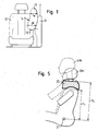
- Figure 1 is a part of a vehicle interior with a front seat 10 and a side structure 12 of the vehicle shown.
- the distance between the Back of the seat 10 and the side structure 12 usually varies between 60 and 140 mm.
- the gas bag 14 has an upper portion 16 and a lower portion 18, wherein the Width W of the lower portion 18, the width w of the upper portion 16th exceeds.
- FIGS. 2a and 2b a distinction is made between a small occupant 20a with a narrow upper body and a large occupant 20b with a wide Upper body. It can be seen that the lower portion 18 of the gas bag 14th regardless of the size of the occupant at the height of the thorax. Due to the widened design of the lower portion 18 is at Unfolding of the gas bag 14, especially with small occupants 20a with a narrow Upper body, the relatively large gap between upper body and side structure 12th closed quickly.
- the gas bag 14 also has two outflow openings 22 and 24 (see Figure 2a).
- the first discharge opening 22 is not in an occupant facing region of the gas bag 14, more specifically in the front region of the arranged lower portion 18.
- the second outflow opening 24 is in one the vehicle occupant area facing the upper portion 16 of the Gas bag 14 is provided.
- the vertical position of the second outflow opening 24 lies in a region 26, which is shown hatched in FIGS. 4 a, 4 b and 5.
- This area 26 is located, with respect to the hip joint 27 of an occupant 20a or 20b, between a height h 1 of 400 mm and a height h 2 of 550 mm.
- the first outflow opening 22 serves to adjust the gas bag internal pressure especially for large occupants 20b with a broad upper body.
- the possibility of Gas outlet from the first outflow opening 22 allows that part of the widened lower portion 18 of the gas bag 14 can be displaced (see FIGS. 2b and 3b). It has been found that for such inmates Dynamic gas bag internal pressure of about 0.6 to 0.8 bar is optimal.
- Dynamic gas bag internal pressure of about 0.6 to 0.8 bar is optimal.
- small Occupant 20a with a narrow upper body attains the gas bag 14 substantially its full extent (see Figures 2a and 3a). Because the second outflow opening 24 is not covered by a small occupant 20a, add up in this Fall the surfaces of the two outflow openings 22 and 24.
- FIG. 6a to 6c Deflection device provided, which lies at least partially in the region 26 and is formed from a piece of fabric 28.
- a first section 30 of the Tissue piece 28 is located directly above the discharge opening 24 and has one of Outflow opening 24 corresponding opening 32.
- One with the first section 30 connected second portion 34 is folded so that it has the two openings 24 and 32 covered.
- the fabric layers 30 and 34 are opposite to two Sided on the outer wall of the gas bag 14, so that the gas only to one Side can escape (see Figure 6c). This site is chosen to be from the Inmates away.
Abstract
Description
Die Erfindung betrifft eine Seitenaufprall-Rückhaltevorrichtung zum Schutz eines auf einem Fahrzeugsitz sitzenden Insassen in einem Kraftfahrzeug, mit einem Gassack, der sich zwischen einer Seitenstruktur des Fahrzeugs und dem Insassen entfaltet.The invention relates to a side impact restraint device for protection a seated in a vehicle seat occupant in a motor vehicle, with a gas bag that extends between a side structure of the vehicle and the Inmates unfolded.
Aus der DE 197 14 266 A1 ist eine gattungsgemäße Seitenaufprallrückhaltevorrichtung bekannt, bei der ein Gassack mit zwei Abschnitten unterschiedlicher Breite in den Spalt zwischen Seitenstruktur und Insassen aufgeblasen wird. Der schmälere obere Abschnitt des Gassacks erstreckt sich auf Höhe des Brustbereichs, der breitere untere Abschnitt auf Höhe des Beckenbereichs.From DE 197 14 266 A1 is a generic side impact restraint device known in which a gas bag with two sections of different Width is inflated in the gap between side structure and occupant. The narrower upper section of the gas bag extends at the level of the chest area, the wider lower section at the level of the pelvic area.
Die DE 100 20 729 A1 zeigt einen Gassack, der sich vorzugsweise aus einem Fahrzeugsitz heraus entfaltet und Abströmöffnungen aufweist, wodurch bei einem Aufprall ein kontrolliertes Gasausblasen möglich ist.DE 100 20 729 A1 shows an airbag, which preferably consists of a Vehicle seat unfolded and has outflow openings, whereby at a Impact a controlled gas blowing is possible.
Aufgabe der Erfindung ist es, eine Seitenaufprallrückhaltevorrichtung mit einem Gassack zu schaffen, der sich an den Körperbau des Insassen anpaßt.The object of the invention is to provide a side impact retention device To create an airbag that adapts to the physique of the occupant.
Zur Lösung dieser Aufgabe wird eine Seitenaufprallrückhaltevorrichtung der eingangs genannten Art vorgeschlagen, bei der der Gassack eine Abströmöffnung aufweist, die in einem dem Insassen zugewandten Bereich des Gassacks angeordnet ist, wobei die vertikale Position der Abströmöffnung so gewählt ist, daß sie vom Oberkörper eines kleinen Insassen nicht abgedeckt wird. Die erfindungsgemäße Anordnung der Abströmöffnung führt dazu, daß sie von großen Insassen verdeckt wird, so daß ein vergleichsweise hoher Innendruck resultiert, während sie bei kleinen Insassen freiliegt, so daß sich ein vergleichsweise niedriger Innendruck ergibt. Die Abströmöffnung ermöglicht somit eine individuelle Abstimmung der Rückhaltewirkung auf den Körperbau des Insassen.To solve this problem, a side impact restraint of the initially proposed type, in which the gas bag has a discharge opening arranged in an occupant facing region of the gas bag arranged is, wherein the vertical position of the discharge opening is chosen so that they from the upper body of a small occupant is not covered. The inventive Arrangement of the discharge opening causes them from large occupants is covered, so that a comparatively high internal pressure results while it is exposed to small occupants, so that a comparatively low internal pressure results. The discharge opening thus allows an individual vote the retention effect on the physique of the occupant.
Optimale Testergebnisse ergeben sich für eine Abströmöffnung, die in einem Bereich liegt, der sich bezogen auf das Hüftgelenk des Insassen zwischen einer Höhe von 400 mm und einer Höhe von 550 mm erstreckt.Optimal test results result for a discharge opening, which in one Range, which relates to the hip joint of the occupant between a Height of 400 mm and a height of 550 mm.
Gemäß einer vorteilhaften Ausführungsform der Erfindung weist der Gassack eine weitere Abströmöffnung auf, die in einem dem Insassen nicht zugewandten Bereich des unteren Abschnitts des Gassacks angeordnet ist. Diese in jedem Fall freiliegende Abströmöffnung sorgt dafür, daß sich die Gassackform und der Gassackinnendruck auch an den Körperbau von großen Insassen individuell anpassen können.According to an advantageous embodiment of the invention, the gas bag another outflow opening, which in a not facing the occupant Area of the lower portion of the airbag is arranged. These in any case exposed discharge opening ensures that the gas bag shape and the Gas bag internal pressure also on the physique of large inmates individually can adjust.
Damit das aus der Abströmöffnung austretende Gas nicht direkt auf den Insassen trifft, ist es zweckmäßig, an der zweiten Abströmöffnung eine Einrichtung zum Ablenken des abströmenden Gases vorzusehen.Thus, the gas emerging from the discharge opening not directly on the Inmates, it is expedient, at the second outlet opening means to provide for deflecting the outflowing gas.
Gemäß der bevorzugten Ausführungsform der Erfindung weist der Gassack im aufgeblasenen Zustand, in Fahrzeuglängsrichtung betrachtet, einen oberen Abschnitt und einen gegenüber dem oberen Abschnitt verbreiterten unteren Abschnitt auf, wobei sich der untere Abschnitt ausschließlich oberhalb des Hüftgelenks des Insassen erstreckt. Die verbreiterte Ausgestaltung des unteren Gassackabschnitts sorgt insbesondere bei Insassen mit schmalem Oberkörper dafür, daß der Spalt zwischen Türverkleidung und Oberkörper schnellstmöglich geschlossen wird. Dementsprechend beginnt die Rückhaltewirkung bei solchen Insassen früher und gestaltet sich dadurch effektiver. Auch bei großen Insassen kann im Falle eines großen Abstands zwischen Sitzlehne und Türverkleidung die Rückhaltewirkung gegenüber herkömmlichen kissenförmigen Gassäcken verbessert werden.According to the preferred embodiment of the invention, the gas bag in inflated state, viewed in the vehicle longitudinal direction, an upper Section and a widened compared to the upper section lower Section on, with the lower section exclusively above the Hip joint of the occupant extends. The broadened design of the lower Airbag section provides especially for inmates with a narrow upper body ensuring that the gap between the door panel and upper body as quickly as possible is closed. Accordingly, the retention effect starts at such Inmates earlier and thus designed more effective. Even with large occupants can in the case of a large distance between the seat back and door trim the Retaining effect improved over conventional pillow-shaped gas bags become.
Weitere Merkmale und Vorteile der Erfindung ergeben sich aus der nachfolgenden Beschreibung und aus den beigefügten Zeichnungen, auf die Bezug genommen wird. In den Zeichnungen zeigen:
- Figur 1 einen Fahrzeugsitz neben einer Seitenstruktur eines Fahrzeugs mit einem aufgeblasenen Gassack einer erfindungsgemäßen Seitenaufprallrückhaltevorrichtung in Fahrzeuglängsrichtung betrachtet;
- Figuren 2a und 2b die Darstellung aus Figur 1 mit einem kleinen bzw. mit einem großen Fahrzeuginsassen;
- Figuren 3a und 3b Schnittansichten entlang der Linien A-A bzw. B-B aus den Figuren 2a und 2b;
- Figuren 4a und 4b die Darstellungen aus den Figuren 2a bzw. 2b in Seitenansicht;
- Figur 5 eine überlagerte Darstellung eines kleinen und eines großen sitzenden Insassen in Seitenansicht;
- Figur 6a eine Draufsicht auf den Gassack im Bereich der zweiten Abströmöffnung;
- Figuren 6b und 6c Schnittansichten entlang der Linien C-C bzw. D-D aus Figur 6a.
- FIG. 1 shows a vehicle seat next to a side structure of a vehicle with an inflated airbag of a side impact restraint device according to the invention viewed in the vehicle longitudinal direction;
- FIGS. 2a and 2b show the illustration from FIG. 1 with a small or with a large vehicle occupant;
- Figures 3a and 3b are sectional views along the lines AA and BB of Figures 2a and 2b;
- Figures 4a and 4b, the representations of Figures 2a and 2b in side view;
- Figure 5 is a superimposed view of a small and a large seated occupant in side view;
- FIG. 6a shows a plan view of the gas bag in the region of the second outflow opening;
- Figures 6b and 6c are sectional views along the lines CC and DD of Figure 6a.
In Figur 1 ist ein Teil eines Fahrzeuginnenraums mit einem Vordersitz 10 und
einer Seitenstruktur 12 des Fahrzeugs dargestellt. Der Abstand zwischen der
Lehne des Sitzes 10 und der Seitenstruktur 12 (Türverkleidung bzw. B-Säule)
variiert in der Regel zwischen 60 und 140 mm. Weiterhin ist ein Gassack 14 zum
Schutz eines Fahrzeuginsassen vor einem Seitenaufprall im aufgeblasenen
Zustand gezeigt, der sich aus der Sitzlehne 10 heraus entfaltet hat. Der Gassack 14
weist einen oberen Abschnitt 16 und einen unteren Abschnitt 18 auf, wobei die
Breite W des unteren Abschnitts 18 die Breite w des oberen Abschnitts 16
übersteigt.In Figure 1 is a part of a vehicle interior with a
In den Figuren 2a und 2b wird unterschieden zwischen einem kleinen Insassen
20a mit schmalem Oberkörper und einem großen Insassen 20b mit breitem
Oberköper. Es ist zu erkennen, daß sich der untere Abschnitt 18 des Gassacks 14
unabhängig von der Größe des Insassen auf Höhe des Thoraxbereichs erstreckt.
Aufgrund der verbreiterten Ausführung des unteren Abschnitts 18 wird beim
Entfalten des Gassacks 14, insbesondere bei kleinen Insassen 20a mit schmalem
Oberkörper, der relativ große Spalt zwischen Oberkörper und Seitenstruktur 12
schnell geschlossen.In FIGS. 2a and 2b, a distinction is made between a
Der Gassack 14 weist ferner zwei Abströmöffnungen 22 und 24 auf (siehe
Figur 2a). Die erste Abströmöffnung 22 ist in einem dem Insassen nicht
zugewandten Bereich des Gassacks 14, genauer gesagt im vorderen Bereich des
unteren Abschnitts 18 angeordnet. Die zweite Abströmöffnung 24 ist in einem
dem Fahrzeuginsassen zugewandten Bereich des oberen Abschnitts 16 des
Gassacks 14 vorgesehen.The
Die vertikale Position der zweiten Abströmöffnung 24 liegt in einem Bereich
26, der in den Figuren 4a, 4b und 5 schraffiert dargestellt ist. Dieser Bereich 26
liegt, bezogen auf das Hüftgelenk 27 eines Insassen 20a oder 20b, zwischen einer
Höhe h1 von 400 mm und einer Höhe h2 von 550 mm.The vertical position of the second outflow opening 24 lies in a
Aus den Figuren 4a und 4b ist ferner zu ersehen, daß aus der ersten
Abströmöffnung 22 unabhängig von der Größe des Insassen immer Gas abströmen
kann. Dagegen wird die zweite Abströmöffnung 24 von großen Insassen 20b
abgedeckt, während sie bei kleinen Insassen 20a zunächst frei bleibt.From FIGS. 4a and 4b it can also be seen that the first
Outflow opening 22 regardless of the size of the occupant always gas flow
can. In contrast, the second outflow opening 24 of
Die erste Abströmöffnung 22 dient zur Einstellung des Gassackinnendrucks
speziell für große Insassen 20b mit breitem Oberkörper. Die Möglichkeit des
Gasaustritts aus der ersten Abströmöffnung 22 erlaubt es, daß ein Teil des
verbreiterten unteren Abschnitts 18 des Gassacks 14 verdrängt werden kann (siehe
Figuren 2b und 3b). Es hat sich herausgestellt, daß für solche Insassen ein
dynamischer Gassackinnendruck von ca. 0,6 bis 0,8 bar optimal ist. Bei kleinen
Insassen 20a mit schmalem Oberkörper erlangt der Gassack 14 im wesentlichen
seine volle Ausdehnung (siehe Figuren 2a und 3a). Da die zweite Abströmöffnung
24 von einem kleinen Insassen 20a nicht abgedeckt wird, addieren sich in diesem
Fall die Flächen der beiden Abströmöffnungen 22 und 24. Durch das Abströmen
von Gas aus beiden Abströmöffnungen 22 und 24 resultiert ein für kleine Insassen
20a optimaler dynamischer Gassackinnendruck von ca. 0,3 bis 0,4 bar. Der
Gassackinnendruck kann also über die Abströmöffnungen 22 und 24 in Abhängigkeit
von der Größe des Insassen gesteuert werden.The first outflow opening 22 serves to adjust the gas bag internal pressure
especially for
Zum Schutz des Insassen vor dem aus der zweiten, dem Insassen zugewandten
Abströmöffnung 24 austretenden Gas ist eine in den Figuren 6a bis 6c gezeigte
Ablenkeinrichtung vorgesehen, die wenigstens teilweise in dem Bereich 26 liegt
und aus einem Gewebestück 28 gebildet ist. Ein erster Abschnitt 30 des
Gewebestücks 28 liegt direkt über der Abströmöffnung 24 und weist eine der
Abströmöffnung 24 entsprechende Öffnung 32 auf. Ein mit dem ersten Abschnitt
30 verbundener zweiter Abschnitt 34 ist so umgelegt, daß er die beiden Öffnungen
24 und 32 überdeckt. Die Gewebelagen 30 und 34 sind an zwei entgegengesetzten
Seiten auf die Außenwand des Gassacks 14 aufgenäht, so daß das Gas nur zu einer
Seite austreten kann (siehe Figur 6c). Diese Seite ist so gewählt, daß sie vom
Insassen weg weist.To protect the occupant from the second, the occupant facing
Outflow opening 24 emerging gas is shown in Figures 6a to 6c
Deflection device provided, which lies at least partially in the
Claims (8)
mit einem Gassack (14), der sich zwischen einer Seitenstruktur (12) des Fahrzeugs und dem Insassen (20a; 20b) entfaltet,
dadurch gekennzeichnet, daß der Gassack (14) eine Abströmöffnung (24) aufweist, die in einem dem Insassen (20a; 20b) zugewandten Bereich des Gassacks (14) angeordnet ist, wobei die vertikale Position der Abströmöffnung (24) so gewählt ist, daß sie vom Oberkörper eines kleinen Insassen (20a) nicht abgedeckt wird.A side impact restraining device for protecting an occupant (20a, 20b) sitting on a vehicle seat (10) in a motor vehicle,
with a gas bag (14) deploying between a side structure (12) of the vehicle and the occupant (20a; 20b),
characterized in that the gas bag (14) has a discharge opening (24) which is arranged in a region of the gas bag (14) facing the occupant (20a; 20b), the vertical position of the discharge opening (24) being selected such that she is not covered by the upper body of a small inmate (20a).
Applications Claiming Priority (2)
| Application Number | Priority Date | Filing Date | Title |
|---|---|---|---|
| DE102004009013 | 2004-02-25 | ||
| DE102004009013A DE102004009013B4 (en) | 2004-02-25 | 2004-02-25 | Side impact restraint device |
Publications (3)
| Publication Number | Publication Date |
|---|---|
| EP1568544A1 true EP1568544A1 (en) | 2005-08-31 |
| EP1568544B1 EP1568544B1 (en) | 2007-01-24 |
| EP1568544B2 EP1568544B2 (en) | 2013-05-22 |
Family
ID=34745264
Family Applications (1)
| Application Number | Title | Priority Date | Filing Date |
|---|---|---|---|
| EP04029547.9A Expired - Fee Related EP1568544B2 (en) | 2004-02-25 | 2004-12-14 | Side impact restraint device |
Country Status (4)
| Country | Link |
|---|---|
| US (1) | US7475904B2 (en) |
| EP (1) | EP1568544B2 (en) |
| DE (2) | DE102004009013B4 (en) |
| ES (1) | ES2279283T5 (en) |
Cited By (5)
| Publication number | Priority date | Publication date | Assignee | Title |
|---|---|---|---|---|
| DE102004048898A1 (en) * | 2004-10-06 | 2006-09-07 | Autoliv Development Ab | Airbag for motor vehicle has a ventilation device with at least one orifice connected to flexible hose |
| WO2009015902A1 (en) * | 2007-08-02 | 2009-02-05 | Autoliv Development Ab | Side airbag having hose as ventilation opening |
| US7850200B2 (en) | 2004-09-01 | 2010-12-14 | Autoliv Development Ab | Airbag and a motor vehicle |
| US8087692B2 (en) | 2006-11-22 | 2012-01-03 | Takata-Petri Ag | Airbag for a motor vehicle |
| DE102009016606B4 (en) * | 2009-04-08 | 2014-08-28 | Autoliv Development Ab | Height-adjustable motor vehicle seat with a side gas bag and motor vehicle with such a vehicle seat |
Families Citing this family (37)
| Publication number | Priority date | Publication date | Assignee | Title |
|---|---|---|---|---|
| DE102004006185B4 (en) * | 2004-02-06 | 2005-12-22 | Autoliv Development Ab | Airbag for installation in a motor vehicle |
| DE102004009013B4 (en) * | 2004-02-25 | 2006-03-16 | Trw Automotive Gmbh | Side impact restraint device |
| JP5007047B2 (en) * | 2006-01-13 | 2012-08-22 | 本田技研工業株式会社 | Airbag device |
| JP5120599B2 (en) * | 2006-06-20 | 2013-01-16 | マツダ株式会社 | Side airbag device |
| JP4245031B2 (en) * | 2006-09-28 | 2009-03-25 | トヨタ自動車株式会社 | Side airbag device for vehicle |
| KR20080045929A (en) * | 2006-11-21 | 2008-05-26 | 현대자동차주식회사 | Vent hole module of air bag |
| US7278656B1 (en) | 2007-01-30 | 2007-10-09 | Key Safety Systems, Inc. | Seat mounted side impact airbag module |
| EP2117882B1 (en) * | 2007-02-14 | 2012-09-19 | Autoliv Development AB | An air-bag for a motor vehicle |
| JP4952321B2 (en) * | 2007-03-20 | 2012-06-13 | 豊田合成株式会社 | Side airbag device |
| US7770921B2 (en) * | 2007-05-25 | 2010-08-10 | Autoliv Development Ab | Airbag for protection of a vehicle occupant |
| US7770917B2 (en) * | 2007-07-12 | 2010-08-10 | Autoliv Asp, Inc. | Inflatable curtain venting |
| KR100999804B1 (en) * | 2007-08-13 | 2010-12-08 | 현대자동차주식회사 | Side air bag |
| US20090289444A1 (en) * | 2008-05-20 | 2009-11-26 | Ramesh Keshavaraj | Airbag, system and method for deploying an airbag |
| DE102008063795A1 (en) | 2008-12-17 | 2009-07-30 | Takata-Petri Ag | Gas bag for passenger restraint system for vehicle seat, bag has shoulder area that is extended in mounted and bloated gas bag at height lateral shoulder region of passenger and has section, which is extended around another section |
| DE102009007179B4 (en) | 2008-12-18 | 2014-10-16 | TAKATA Aktiengesellschaft | A gas bag assembly for a vehicle occupant restraint system and method for protecting a vehicle occupant |
| US8408591B2 (en) * | 2009-04-17 | 2013-04-02 | Autoliv Asp, Inc. | Inflatable curtain airbags with expanded-volume lower portions for ejection mitigation |
| KR101081274B1 (en) * | 2009-09-07 | 2011-11-08 | 현대모비스 주식회사 | A passinger airbag apparatus |
| JP6075935B2 (en) * | 2011-02-28 | 2017-02-08 | 富士重工業株式会社 | Occupant protection device and occupant protection method |
| JP2012179956A (en) | 2011-02-28 | 2012-09-20 | Fuji Heavy Ind Ltd | Occupant protection apparatus and occupant protection method |
| JP5401495B2 (en) * | 2011-03-17 | 2014-01-29 | 富士重工業株式会社 | Side airbag device, occupant protection device, and occupant protection method |
| EP2718155B1 (en) | 2011-06-08 | 2015-08-12 | TRW Automotive GmbH | Vehicle occupant restraint system having an adaptive knee airbag |
| GB201113411D0 (en) * | 2011-08-04 | 2011-09-21 | Ford Global Tech Llc | An airbag having a pressure responsive vent |
| US9327673B2 (en) * | 2011-08-31 | 2016-05-03 | Toyota Jidosha Kabushiki Kaisha | Vehicle side airbag device |
| DE102011053934B4 (en) * | 2011-09-26 | 2013-11-28 | Autoliv Development Ab | Airbag with a gas guide device associated with its vent opening |
| DE102012011035A1 (en) | 2012-06-05 | 2013-12-05 | Trw Automotive Gmbh | Adaptive knee airbag for a vehicle occupant restraint device |
| JP6217350B2 (en) * | 2013-11-29 | 2017-10-25 | 三菱自動車工業株式会社 | Side airbag device |
| US9580039B2 (en) | 2014-04-22 | 2017-02-28 | Autoliv Asp, Inc. | Multi-chamber airbag with unidirectional vent |
| KR102310283B1 (en) * | 2014-10-17 | 2021-10-07 | 현대모비스 주식회사 | Curtain Airbag Apparatus Of Vehicle |
| DE102014116433B4 (en) * | 2014-11-11 | 2016-12-08 | Autoliv Development Ab | Airbag arrangement with a blank forming a guide device |
| US9533652B1 (en) * | 2015-07-14 | 2017-01-03 | Autoliv Asp, Inc. | One-directional valve for multi-chamber airbags |
| US9815429B2 (en) * | 2016-02-23 | 2017-11-14 | Autoliv Asp, Inc. | Adaptive vent for knee airbag |
| JP6626763B2 (en) * | 2016-03-31 | 2019-12-25 | 株式会社Subaru | Vehicle occupant protection device |
| US9643562B1 (en) * | 2016-05-05 | 2017-05-09 | Autoliv Asp, Inc. | Airbag with passive adaptive venting |
| KR102098372B1 (en) * | 2016-05-20 | 2020-04-07 | 오토리브 디벨로프먼트 에이비 | Side airbag device |
| US10293777B2 (en) | 2016-08-26 | 2019-05-21 | Autoliv Asp, Inc. | Multi-cushion airbag assemblies for reducing rotational velocity of an occupant's head |
| JP6729496B2 (en) * | 2017-06-05 | 2020-07-22 | 豊田合成株式会社 | Side airbag device |
| DE202017105668U1 (en) | 2017-09-19 | 2017-10-09 | Trw Vehicle Safety Systems Inc. | Front-restraint |
Citations (7)
| Publication number | Priority date | Publication date | Assignee | Title |
|---|---|---|---|---|
| US5556128A (en) * | 1994-11-24 | 1996-09-17 | Volkswagen Ag | Safety arrangement for a vehicle occupant |
| US20010017458A1 (en) * | 2000-02-24 | 2001-08-30 | Trw Occupant Restraint Systems Gmbh & Co, Kg | Side impact protection device |
| FR2805505A1 (en) * | 2000-02-24 | 2001-08-31 | Aerazur | Automotive vehicle airbag arrangement, has elastic membrane which, on deformation due to collusion of the user with the bag, allows slow escape of gas through vent |
| DE10020729A1 (en) * | 2000-04-27 | 2001-10-31 | Volkswagen Ag | Vehicle safety device with at least one airbag module has separate side airbag modules each filled by airbag lances |
| US20020047253A1 (en) * | 2000-04-12 | 2002-04-25 | Georg Rasch | Airbag arrangement |
| US20020096869A1 (en) * | 2001-01-23 | 2002-07-25 | Honda Giken Kogyo Kabushiki Kaisha | Air bag apparatus for side crash |
| US20030178831A1 (en) * | 2002-03-21 | 2003-09-25 | Brad Roberts | Side-impact, variable thickness vehicular airbag |
Family Cites Families (53)
| Publication number | Priority date | Publication date | Assignee | Title |
|---|---|---|---|---|
| US2959426A (en) * | 1958-10-21 | 1960-11-08 | Bendix Westinghouse Automotive | Multiple range control valve for air spring |
| US3511519A (en) † | 1967-08-25 | 1970-05-12 | Eaton Yale & Towne | Vehicle safety mechanism |
| US3573885A (en) * | 1968-12-18 | 1971-04-06 | Eaton Yale & Towne | Vehicle safety apparatus for restraining occupant |
| US3887213A (en) * | 1973-02-28 | 1975-06-03 | Eaton Corp | Inflatable vehicle occupant restraint and system therefor |
| US4111458A (en) * | 1975-11-20 | 1978-09-05 | Honda Giken Kogyo Kabushiki Kaisha | Safety air cushion bag in automotive vehicles |
| US4181325A (en) * | 1978-03-06 | 1980-01-01 | General Motors Corporation | Occupant restraint cushion |
| US6715790B2 (en) * | 1994-05-23 | 2004-04-06 | Automotive Technologies International, Inc. | Side curtain air bag |
| US20040256842A1 (en) * | 1994-05-23 | 2004-12-23 | Breed David S. | Knee bolster airbag system |
| US6648367B2 (en) * | 1995-06-07 | 2003-11-18 | Automotive Technologies International Inc. | Integrated occupant protection system |
| JP2731324B2 (en) * | 1992-06-17 | 1998-03-25 | 株式会社東海理化電機製作所 | Air bag device bag and method of manufacturing bag |
| US5310215A (en) * | 1993-01-13 | 1994-05-10 | Trw Vehicle Safety Systems Inc. | Apparatus for venting of an inflatable air bag |
| US5839755A (en) * | 1994-03-03 | 1998-11-24 | Trw Vehicle Safety Systems Inc. | Method and apparatus for restraining a vehicle occupant |
| US20060202452A1 (en) * | 1994-05-23 | 2006-09-14 | Automotive Technologies International, Inc. | Side curtain and multi-compartment vehicular airbags |
| US7338069B2 (en) * | 2004-04-02 | 2008-03-04 | Automotive Technologies International, Inc. | Airbags with internal valves |
| US5496061A (en) † | 1995-03-31 | 1996-03-05 | Trw Vehicle Safety Systems Inc. | Seat mounted air bag assembly |
| US5913536A (en) * | 1996-02-07 | 1999-06-22 | Trw Vehicle Safety System Inc. | Air bag module |
| JP3374648B2 (en) * | 1996-04-08 | 2003-02-10 | 三菱自動車工業株式会社 | Airbag for side impact |
| JP2894274B2 (en) * | 1996-04-08 | 1999-05-24 | 三菱自動車工業株式会社 | Airbag for side impact |
| JP2962224B2 (en) * | 1996-04-08 | 1999-10-12 | 三菱自動車工業株式会社 | Airbag for side impact |
| US5669628A (en) * | 1996-04-08 | 1997-09-23 | Morton International, Inc. | Air bag cushion protection during both normal and out of position deployments |
| JP2962225B2 (en) * | 1996-04-08 | 1999-10-12 | 三菱自動車工業株式会社 | Airbag for side impact |
| JP3685873B2 (en) * | 1996-06-19 | 2005-08-24 | 本田技研工業株式会社 | Airbag device for motorcycle |
| DE19633883C2 (en) † | 1996-08-19 | 1998-07-02 | Petri Ag | Airbag for an airbag module |
| DE29709389U1 (en) * | 1997-05-28 | 1997-09-25 | Trw Repa Gmbh | Airbag for an occupant restraint system in vehicles |
| US6206411B1 (en) * | 1997-09-19 | 2001-03-27 | Nissan Motor Co., Ltd. | Apparatus for protecting crew member of automobile when collision of side portion thereof occurs |
| DE29804005U1 (en) † | 1998-03-06 | 1998-07-02 | Trw Repa Gmbh | Airbag for a vehicle occupant restraint system |
| JP4129758B2 (en) * | 1998-08-10 | 2008-08-06 | 俊毅 内田 | Airbag device |
| DE29906477U1 (en) † | 1999-04-06 | 1999-08-12 | Petri Ag | Airbag unit |
| JP3595998B2 (en) * | 1999-04-07 | 2004-12-02 | マツダ株式会社 | Vehicle side airbag device |
| JP3463598B2 (en) † | 1999-04-13 | 2003-11-05 | トヨタ自動車株式会社 | Airbag device |
| DE20000144U1 (en) † | 2000-01-05 | 2000-05-11 | Trw Repa Gmbh | Vehicle occupant restraint system |
| DE10032791A1 (en) † | 2000-06-28 | 2002-01-24 | Takata Petri Ag | Airbag module with pressure relief opening in air sack venting into air bag module |
| CN100398362C (en) * | 2001-06-08 | 2008-07-02 | 丰田合成株式会社 | Side air bag device |
| EP1393997A4 (en) * | 2001-06-08 | 2008-03-26 | Toyoda Gosei Kk | Side airbag device |
| JP2003034215A (en) * | 2001-07-23 | 2003-02-04 | Takata Corp | Device for occupant protection |
| DE20207388U1 (en) † | 2001-11-02 | 2002-08-14 | Takata Petri Gmbh Ulm | An air bag assembly |
| US7055853B2 (en) * | 2002-01-31 | 2006-06-06 | Honda Giken Kogyo Kabushiki Kaisha | Side airbag apparatus |
| US20030168836A1 (en) * | 2002-03-11 | 2003-09-11 | Eiji Sato | Side airbag apparatus |
| US6932386B2 (en) * | 2002-07-01 | 2005-08-23 | Honda Giken Kogyo Kabushiki Kaisha | Occupant restraint system including side airbag with vent hole |
| US6832778B2 (en) † | 2002-07-19 | 2004-12-21 | Delphi Technologies, Inc. | Air bag restraint including selectively operable venting elements |
| US6945559B2 (en) * | 2002-09-19 | 2005-09-20 | Delphi Technologies, Inc. | Method and apparatus for air bag venting |
| JP4161705B2 (en) * | 2002-12-19 | 2008-10-08 | タカタ株式会社 | Side airbag and side airbag device |
| JP4285167B2 (en) * | 2003-01-30 | 2009-06-24 | タカタ株式会社 | Side airbag device |
| US6883831B2 (en) * | 2003-02-06 | 2005-04-26 | Delphi Technologies, Inc. | Apparatus and method for controlling an inflatable cushion |
| GB2400355B (en) * | 2003-04-10 | 2006-05-24 | Autoliv Dev | Improvements in or relating to an air-bag |
| JP2005047471A (en) * | 2003-07-31 | 2005-02-24 | Toyoda Gosei Co Ltd | Method for folding air bag and air bag device |
| EP1711381B1 (en) * | 2004-01-23 | 2012-04-11 | Takata - Petri Ag | Side protection device |
| DE102004004544A1 (en) | 2004-01-23 | 2005-08-11 | Takata-Petri (Ulm) Gmbh | Passenger protection system for vehicles comprises a side airbag having an opening from which gas can penetrate |
| DE102004006185B4 (en) † | 2004-02-06 | 2005-12-22 | Autoliv Development Ab | Airbag for installation in a motor vehicle |
| DE102004009013B4 (en) * | 2004-02-25 | 2006-03-16 | Trw Automotive Gmbh | Side impact restraint device |
| US20060012155A1 (en) * | 2004-07-01 | 2006-01-19 | Ford Global Technologies, Llc | Vehicle side airbag apparatus and seat containing same |
| JP2006281968A (en) * | 2005-03-31 | 2006-10-19 | Nippon Plast Co Ltd | Air bag and air bag device |
| DE202006017996U1 (en) † | 2006-11-22 | 2007-02-15 | Takata-Petri Ag | Airbag for a vehicle comprises sleeve sections each forming an airbag layer which are connected together forming the airbag sleeve and are separated from each other when the airbag is expanded |
-
2004
- 2004-02-25 DE DE102004009013A patent/DE102004009013B4/en not_active Revoked
- 2004-12-14 ES ES04029547T patent/ES2279283T5/en active Active
- 2004-12-14 EP EP04029547.9A patent/EP1568544B2/en not_active Expired - Fee Related
- 2004-12-14 DE DE502004002766T patent/DE502004002766D1/en active Active
-
2005
- 2005-01-31 US US11/047,113 patent/US7475904B2/en active Active
Patent Citations (7)
| Publication number | Priority date | Publication date | Assignee | Title |
|---|---|---|---|---|
| US5556128A (en) * | 1994-11-24 | 1996-09-17 | Volkswagen Ag | Safety arrangement for a vehicle occupant |
| US20010017458A1 (en) * | 2000-02-24 | 2001-08-30 | Trw Occupant Restraint Systems Gmbh & Co, Kg | Side impact protection device |
| FR2805505A1 (en) * | 2000-02-24 | 2001-08-31 | Aerazur | Automotive vehicle airbag arrangement, has elastic membrane which, on deformation due to collusion of the user with the bag, allows slow escape of gas through vent |
| US20020047253A1 (en) * | 2000-04-12 | 2002-04-25 | Georg Rasch | Airbag arrangement |
| DE10020729A1 (en) * | 2000-04-27 | 2001-10-31 | Volkswagen Ag | Vehicle safety device with at least one airbag module has separate side airbag modules each filled by airbag lances |
| US20020096869A1 (en) * | 2001-01-23 | 2002-07-25 | Honda Giken Kogyo Kabushiki Kaisha | Air bag apparatus for side crash |
| US20030178831A1 (en) * | 2002-03-21 | 2003-09-25 | Brad Roberts | Side-impact, variable thickness vehicular airbag |
Cited By (6)
| Publication number | Priority date | Publication date | Assignee | Title |
|---|---|---|---|---|
| US7850200B2 (en) | 2004-09-01 | 2010-12-14 | Autoliv Development Ab | Airbag and a motor vehicle |
| DE102004048898A1 (en) * | 2004-10-06 | 2006-09-07 | Autoliv Development Ab | Airbag for motor vehicle has a ventilation device with at least one orifice connected to flexible hose |
| US8087692B2 (en) | 2006-11-22 | 2012-01-03 | Takata-Petri Ag | Airbag for a motor vehicle |
| US8267426B2 (en) | 2006-11-22 | 2012-09-18 | Takata AG | Airbag for a motor vehicle |
| WO2009015902A1 (en) * | 2007-08-02 | 2009-02-05 | Autoliv Development Ab | Side airbag having hose as ventilation opening |
| DE102009016606B4 (en) * | 2009-04-08 | 2014-08-28 | Autoliv Development Ab | Height-adjustable motor vehicle seat with a side gas bag and motor vehicle with such a vehicle seat |
Also Published As
| Publication number | Publication date |
|---|---|
| EP1568544B1 (en) | 2007-01-24 |
| US7475904B2 (en) | 2009-01-13 |
| DE502004002766D1 (en) | 2007-03-15 |
| DE102004009013A1 (en) | 2005-09-22 |
| DE102004009013B4 (en) | 2006-03-16 |
| EP1568544B2 (en) | 2013-05-22 |
| ES2279283T5 (en) | 2013-09-03 |
| ES2279283T3 (en) | 2007-08-16 |
| US20050184493A1 (en) | 2005-08-25 |
Similar Documents
| Publication | Publication Date | Title |
|---|---|---|
| DE102004009013B4 (en) | Side impact restraint device | |
| EP0832795B1 (en) | Restraint device for a vehicle passenger | |
| DE60031115T2 (en) | INFLATABLE AIRBAG FOR A MOTOR VEHICLE | |
| DE102005002085B4 (en) | Side air bag device | |
| EP1364840B1 (en) | Driver or passenger air bag | |
| DE102013221983B4 (en) | Curtain airbag for a vehicle and a restraint assembly | |
| DE10024293B4 (en) | Air bag assembly | |
| DE102010056342A1 (en) | Curtain airbag for a vehicle | |
| DE202006010878U1 (en) | Airbag arrangement for vehicle occupant restraint system has chamber section that extends forward when airbag inflated to protect occupant including for forward occupant movements at angle by catching associated occupant body regions | |
| EP0771698A2 (en) | Side-impact airbag protection device | |
| EP1058633B1 (en) | Airbag module | |
| DE10007343A1 (en) | Safety device for vehicle occupants, especially for motor vehicle, has airbag arrangement with additional rollover airbag for unfolding over large area beneath roof seat position(s) | |
| DE10063473B4 (en) | Roof railing for inflatable restraint system | |
| DE102004026778A1 (en) | Protective device for vehicle occupants and motor vehicle with a protective device | |
| DE60313337T2 (en) | Impact protection and its method | |
| DE102022106720A1 (en) | ROOF-MOUNTED AIRBAG PROTECTS CENTER AND OUTSIDE FRONT ROW PASSENGERS IN FRONTAL, OFFSET AND ANGLE IMPACT MODES | |
| DE60211394T2 (en) | Head protection air bag device | |
| DE19745872A1 (en) | Air-bag device for automobile | |
| EP1426244B1 (en) | Vehicle with a body structure and a side collision protection device | |
| DE102004014742B4 (en) | Vehicle with curtain airbag | |
| DE60207000T2 (en) | Airbag for the head protection of vehicle occupants | |
| EP1227014B1 (en) | Vehicle occupant restraining device | |
| DE19519998C2 (en) | Passenger airbag module | |
| DE102005035196B4 (en) | The vehicle occupant restraint system | |
| DE19604014A1 (en) | Device for protecting occupants of a motor vehicle |
Legal Events
| Date | Code | Title | Description |
|---|---|---|---|
| PUAI | Public reference made under article 153(3) epc to a published international application that has entered the european phase |
Free format text: ORIGINAL CODE: 0009012 |
|
| AK | Designated contracting states |
Kind code of ref document: A1 Designated state(s): AT BE BG CH CY CZ DE DK EE ES FI FR GB GR HU IE IS IT LI LT LU MC NL PL PT RO SE SI SK TR |
|
| AX | Request for extension of the european patent |
Extension state: AL BA HR LV MK YU |
|
| 17P | Request for examination filed |
Effective date: 20060207 |
|
| AKX | Designation fees paid |
Designated state(s): DE ES FR IT |
|
| GRAP | Despatch of communication of intention to grant a patent |
Free format text: ORIGINAL CODE: EPIDOSNIGR1 |
|
| GRAJ | Information related to disapproval of communication of intention to grant by the applicant or resumption of examination proceedings by the epo deleted |
Free format text: ORIGINAL CODE: EPIDOSDIGR1 |
|
| GRAP | Despatch of communication of intention to grant a patent |
Free format text: ORIGINAL CODE: EPIDOSNIGR1 |
|
| RIC1 | Information provided on ipc code assigned before grant |
Ipc: B60R 21/16 20060101AFI20060811BHEP |
|
| GRAS | Grant fee paid |
Free format text: ORIGINAL CODE: EPIDOSNIGR3 |
|
| GRAA | (expected) grant |
Free format text: ORIGINAL CODE: 0009210 |
|
| AK | Designated contracting states |
Kind code of ref document: B1 Designated state(s): DE ES FR IT |
|
| REF | Corresponds to: |
Ref document number: 502004002766 Country of ref document: DE Date of ref document: 20070315 Kind code of ref document: P |
|
| ET | Fr: translation filed | ||
| REG | Reference to a national code |
Ref country code: ES Ref legal event code: FG2A Ref document number: 2279283 Country of ref document: ES Kind code of ref document: T3 |
|
| PLBI | Opposition filed |
Free format text: ORIGINAL CODE: 0009260 |
|
| 26 | Opposition filed |
Opponent name: TAKATA-PETRI AG Effective date: 20071023 |
|
| PLAX | Notice of opposition and request to file observation + time limit sent |
Free format text: ORIGINAL CODE: EPIDOSNOBS2 |
|
| PLBB | Reply of patent proprietor to notice(s) of opposition received |
Free format text: ORIGINAL CODE: EPIDOSNOBS3 |
|
| APAH | Appeal reference modified |
Free format text: ORIGINAL CODE: EPIDOSCREFNO |
|
| APBM | Appeal reference recorded |
Free format text: ORIGINAL CODE: EPIDOSNREFNO |
|
| APBP | Date of receipt of notice of appeal recorded |
Free format text: ORIGINAL CODE: EPIDOSNNOA2O |
|
| APBQ | Date of receipt of statement of grounds of appeal recorded |
Free format text: ORIGINAL CODE: EPIDOSNNOA3O |
|
| APBU | Appeal procedure closed |
Free format text: ORIGINAL CODE: EPIDOSNNOA9O |
|
| PUAH | Patent maintained in amended form |
Free format text: ORIGINAL CODE: 0009272 |
|
| STAA | Information on the status of an ep patent application or granted ep patent |
Free format text: STATUS: PATENT MAINTAINED AS AMENDED |
|
| 27A | Patent maintained in amended form |
Effective date: 20130522 |
|
| AK | Designated contracting states |
Kind code of ref document: B2 Designated state(s): DE ES FR IT |
|
| REG | Reference to a national code |
Ref country code: DE Ref legal event code: R102 Ref document number: 502004002766 Country of ref document: DE Effective date: 20130522 |
|
| REG | Reference to a national code |
Ref country code: ES Ref legal event code: DC2A Ref document number: 2279283 Country of ref document: ES Kind code of ref document: T5 Effective date: 20130903 |
|
| REG | Reference to a national code |
Ref country code: FR Ref legal event code: PLFP Year of fee payment: 12 |
|
| REG | Reference to a national code |
Ref country code: FR Ref legal event code: PLFP Year of fee payment: 13 |
|
| PG25 | Lapsed in a contracting state [announced via postgrant information from national office to epo] |
Ref country code: IT Free format text: LAPSE BECAUSE OF NON-PAYMENT OF DUE FEES Effective date: 20151214 |
|
| PG25 | Lapsed in a contracting state [announced via postgrant information from national office to epo] |
Ref country code: IT Free format text: LAPSE BECAUSE OF NON-PAYMENT OF DUE FEES Effective date: 20151214 |
|
| PGRI | Patent reinstated in contracting state [announced from national office to epo] |
Ref country code: IT Effective date: 20170710 |
|
| REG | Reference to a national code |
Ref country code: FR Ref legal event code: PLFP Year of fee payment: 14 |
|
| PGFP | Annual fee paid to national office [announced via postgrant information from national office to epo] |
Ref country code: DE Payment date: 20191231 Year of fee payment: 16 |
|
| PGFP | Annual fee paid to national office [announced via postgrant information from national office to epo] |
Ref country code: FR Payment date: 20191226 Year of fee payment: 16 Ref country code: IT Payment date: 20191219 Year of fee payment: 16 |
|
| PGFP | Annual fee paid to national office [announced via postgrant information from national office to epo] |
Ref country code: ES Payment date: 20200102 Year of fee payment: 16 |
|
| REG | Reference to a national code |
Ref country code: DE Ref legal event code: R081 Ref document number: 502004002766 Country of ref document: DE Owner name: ZF AUTOMOTIVE GERMANY GMBH, DE Free format text: FORMER OWNER: TRW AUTOMOTIVE GMBH, 73553 ALFDORF, DE Ref country code: DE Ref legal event code: R082 Ref document number: 502004002766 Country of ref document: DE Representative=s name: PRINZ & PARTNER MBB PATENTANWAELTE RECHTSANWAE, DE |
|
| REG | Reference to a national code |
Ref country code: DE Ref legal event code: R119 Ref document number: 502004002766 Country of ref document: DE |
|
| PG25 | Lapsed in a contracting state [announced via postgrant information from national office to epo] |
Ref country code: FR Free format text: LAPSE BECAUSE OF NON-PAYMENT OF DUE FEES Effective date: 20201231 |
|
| PG25 | Lapsed in a contracting state [announced via postgrant information from national office to epo] |
Ref country code: DE Free format text: LAPSE BECAUSE OF NON-PAYMENT OF DUE FEES Effective date: 20210701 |
|
| REG | Reference to a national code |
Ref country code: ES Ref legal event code: FD2A Effective date: 20220221 |
|
| PG25 | Lapsed in a contracting state [announced via postgrant information from national office to epo] |
Ref country code: ES Free format text: LAPSE BECAUSE OF NON-PAYMENT OF DUE FEES Effective date: 20201215 |
|
| PG25 | Lapsed in a contracting state [announced via postgrant information from national office to epo] |
Ref country code: IT Free format text: LAPSE BECAUSE OF NON-PAYMENT OF DUE FEES Effective date: 20201214 |