EP1572041B1 - Intervertebral implant and insertion tool for inserting same - Google Patents
Intervertebral implant and insertion tool for inserting same Download PDFInfo
- Publication number
- EP1572041B1 EP1572041B1 EP03813356A EP03813356A EP1572041B1 EP 1572041 B1 EP1572041 B1 EP 1572041B1 EP 03813356 A EP03813356 A EP 03813356A EP 03813356 A EP03813356 A EP 03813356A EP 1572041 B1 EP1572041 B1 EP 1572041B1
- Authority
- EP
- European Patent Office
- Prior art keywords
- implant
- keel
- recess
- anterior
- vertebrae
- Prior art date
- Legal status (The legal status is an assumption and is not a legal conclusion. Google has not performed a legal analysis and makes no representation as to the accuracy of the status listed.)
- Expired - Lifetime
Links
- 239000007943 implant Substances 0.000 title claims description 90
- 238000003780 insertion Methods 0.000 title claims description 46
- 230000037431 insertion Effects 0.000 title claims description 46
- 239000004033 plastic Substances 0.000 claims description 18
- 229920003023 plastic Polymers 0.000 claims description 18
- 230000033001 locomotion Effects 0.000 claims description 15
- 238000007373 indentation Methods 0.000 claims description 14
- 238000005452 bending Methods 0.000 claims description 6
- 230000006872 improvement Effects 0.000 description 3
- 210000004705 lumbosacral region Anatomy 0.000 description 3
- RTAQQCXQSZGOHL-UHFFFAOYSA-N Titanium Chemical compound [Ti] RTAQQCXQSZGOHL-UHFFFAOYSA-N 0.000 description 2
- 239000011248 coating agent Substances 0.000 description 2
- 238000000576 coating method Methods 0.000 description 2
- 238000011161 development Methods 0.000 description 2
- 230000018109 developmental process Effects 0.000 description 2
- 239000010936 titanium Substances 0.000 description 2
- 229910052719 titanium Inorganic materials 0.000 description 2
- MTHLBYMFGWSRME-UHFFFAOYSA-N [Cr].[Co].[Mo] Chemical compound [Cr].[Co].[Mo] MTHLBYMFGWSRME-UHFFFAOYSA-N 0.000 description 1
- 238000004873 anchoring Methods 0.000 description 1
- 238000011882 arthroplasty Methods 0.000 description 1
- 230000008901 benefit Effects 0.000 description 1
- 230000015572 biosynthetic process Effects 0.000 description 1
- 239000000919 ceramic Substances 0.000 description 1
- 230000006835 compression Effects 0.000 description 1
- 238000007906 compression Methods 0.000 description 1
- 238000010276 construction Methods 0.000 description 1
- 238000013461 design Methods 0.000 description 1
- 229920001903 high density polyethylene Polymers 0.000 description 1
- 239000004700 high-density polyethylene Substances 0.000 description 1
- 230000009545 invasion Effects 0.000 description 1
- 239000000463 material Substances 0.000 description 1
- 230000007246 mechanism Effects 0.000 description 1
- 238000012986 modification Methods 0.000 description 1
- 230000004048 modification Effects 0.000 description 1
- 238000002360 preparation method Methods 0.000 description 1
- 230000008439 repair process Effects 0.000 description 1
- 230000000630 rising effect Effects 0.000 description 1
- 239000007787 solid Substances 0.000 description 1
- 239000010935 stainless steel Substances 0.000 description 1
- 229910001220 stainless steel Inorganic materials 0.000 description 1
- 238000013519 translation Methods 0.000 description 1
Images


Classifications
-
- A—HUMAN NECESSITIES
- A61—MEDICAL OR VETERINARY SCIENCE; HYGIENE
- A61F—FILTERS IMPLANTABLE INTO BLOOD VESSELS; PROSTHESES; DEVICES PROVIDING PATENCY TO, OR PREVENTING COLLAPSING OF, TUBULAR STRUCTURES OF THE BODY, e.g. STENTS; ORTHOPAEDIC, NURSING OR CONTRACEPTIVE DEVICES; FOMENTATION; TREATMENT OR PROTECTION OF EYES OR EARS; BANDAGES, DRESSINGS OR ABSORBENT PADS; FIRST-AID KITS
- A61F2/00—Filters implantable into blood vessels; Prostheses, i.e. artificial substitutes or replacements for parts of the body; Appliances for connecting them with the body; Devices providing patency to, or preventing collapsing of, tubular structures of the body, e.g. stents
- A61F2/02—Prostheses implantable into the body
- A61F2/30—Joints
- A61F2/44—Joints for the spine, e.g. vertebrae, spinal discs
- A61F2/442—Intervertebral or spinal discs, e.g. resilient
- A61F2/4425—Intervertebral or spinal discs, e.g. resilient made of articulated components
-
- A—HUMAN NECESSITIES
- A61—MEDICAL OR VETERINARY SCIENCE; HYGIENE
- A61F—FILTERS IMPLANTABLE INTO BLOOD VESSELS; PROSTHESES; DEVICES PROVIDING PATENCY TO, OR PREVENTING COLLAPSING OF, TUBULAR STRUCTURES OF THE BODY, e.g. STENTS; ORTHOPAEDIC, NURSING OR CONTRACEPTIVE DEVICES; FOMENTATION; TREATMENT OR PROTECTION OF EYES OR EARS; BANDAGES, DRESSINGS OR ABSORBENT PADS; FIRST-AID KITS
- A61F2/00—Filters implantable into blood vessels; Prostheses, i.e. artificial substitutes or replacements for parts of the body; Appliances for connecting them with the body; Devices providing patency to, or preventing collapsing of, tubular structures of the body, e.g. stents
- A61F2/02—Prostheses implantable into the body
- A61F2/30—Joints
- A61F2/30767—Special external or bone-contacting surface, e.g. coating for improving bone ingrowth
- A61F2/30771—Special external or bone-contacting surface, e.g. coating for improving bone ingrowth applied in original prostheses, e.g. holes or grooves
-
- A—HUMAN NECESSITIES
- A61—MEDICAL OR VETERINARY SCIENCE; HYGIENE
- A61F—FILTERS IMPLANTABLE INTO BLOOD VESSELS; PROSTHESES; DEVICES PROVIDING PATENCY TO, OR PREVENTING COLLAPSING OF, TUBULAR STRUCTURES OF THE BODY, e.g. STENTS; ORTHOPAEDIC, NURSING OR CONTRACEPTIVE DEVICES; FOMENTATION; TREATMENT OR PROTECTION OF EYES OR EARS; BANDAGES, DRESSINGS OR ABSORBENT PADS; FIRST-AID KITS
- A61F2/00—Filters implantable into blood vessels; Prostheses, i.e. artificial substitutes or replacements for parts of the body; Appliances for connecting them with the body; Devices providing patency to, or preventing collapsing of, tubular structures of the body, e.g. stents
- A61F2/02—Prostheses implantable into the body
- A61F2/30—Joints
- A61F2/46—Special tools or methods for implanting or extracting artificial joints, accessories, bone grafts or substitutes, or particular adaptations therefor
- A61F2/4603—Special tools or methods for implanting or extracting artificial joints, accessories, bone grafts or substitutes, or particular adaptations therefor for insertion or extraction of endoprosthetic joints or of accessories thereof
- A61F2/4611—Special tools or methods for implanting or extracting artificial joints, accessories, bone grafts or substitutes, or particular adaptations therefor for insertion or extraction of endoprosthetic joints or of accessories thereof of spinal prostheses
-
- A—HUMAN NECESSITIES
- A61—MEDICAL OR VETERINARY SCIENCE; HYGIENE
- A61F—FILTERS IMPLANTABLE INTO BLOOD VESSELS; PROSTHESES; DEVICES PROVIDING PATENCY TO, OR PREVENTING COLLAPSING OF, TUBULAR STRUCTURES OF THE BODY, e.g. STENTS; ORTHOPAEDIC, NURSING OR CONTRACEPTIVE DEVICES; FOMENTATION; TREATMENT OR PROTECTION OF EYES OR EARS; BANDAGES, DRESSINGS OR ABSORBENT PADS; FIRST-AID KITS
- A61F2/00—Filters implantable into blood vessels; Prostheses, i.e. artificial substitutes or replacements for parts of the body; Appliances for connecting them with the body; Devices providing patency to, or preventing collapsing of, tubular structures of the body, e.g. stents
- A61F2/02—Prostheses implantable into the body
- A61F2/30—Joints
- A61F2002/30001—Additional features of subject-matter classified in A61F2/28, A61F2/30 and subgroups thereof
- A61F2002/30316—The prosthesis having different structural features at different locations within the same prosthesis; Connections between prosthetic parts; Special structural features of bone or joint prostheses not otherwise provided for
- A61F2002/30329—Connections or couplings between prosthetic parts, e.g. between modular parts; Connecting elements
- A61F2002/30383—Connections or couplings between prosthetic parts, e.g. between modular parts; Connecting elements made by laterally inserting a protrusion, e.g. a rib into a complementarily-shaped groove
-
- A—HUMAN NECESSITIES
- A61—MEDICAL OR VETERINARY SCIENCE; HYGIENE
- A61F—FILTERS IMPLANTABLE INTO BLOOD VESSELS; PROSTHESES; DEVICES PROVIDING PATENCY TO, OR PREVENTING COLLAPSING OF, TUBULAR STRUCTURES OF THE BODY, e.g. STENTS; ORTHOPAEDIC, NURSING OR CONTRACEPTIVE DEVICES; FOMENTATION; TREATMENT OR PROTECTION OF EYES OR EARS; BANDAGES, DRESSINGS OR ABSORBENT PADS; FIRST-AID KITS
- A61F2/00—Filters implantable into blood vessels; Prostheses, i.e. artificial substitutes or replacements for parts of the body; Appliances for connecting them with the body; Devices providing patency to, or preventing collapsing of, tubular structures of the body, e.g. stents
- A61F2/02—Prostheses implantable into the body
- A61F2/30—Joints
- A61F2002/30001—Additional features of subject-matter classified in A61F2/28, A61F2/30 and subgroups thereof
- A61F2002/30316—The prosthesis having different structural features at different locations within the same prosthesis; Connections between prosthetic parts; Special structural features of bone or joint prostheses not otherwise provided for
- A61F2002/30329—Connections or couplings between prosthetic parts, e.g. between modular parts; Connecting elements
- A61F2002/30476—Connections or couplings between prosthetic parts, e.g. between modular parts; Connecting elements locked by an additional locking mechanism
- A61F2002/305—Snap connection
-
- A—HUMAN NECESSITIES
- A61—MEDICAL OR VETERINARY SCIENCE; HYGIENE
- A61F—FILTERS IMPLANTABLE INTO BLOOD VESSELS; PROSTHESES; DEVICES PROVIDING PATENCY TO, OR PREVENTING COLLAPSING OF, TUBULAR STRUCTURES OF THE BODY, e.g. STENTS; ORTHOPAEDIC, NURSING OR CONTRACEPTIVE DEVICES; FOMENTATION; TREATMENT OR PROTECTION OF EYES OR EARS; BANDAGES, DRESSINGS OR ABSORBENT PADS; FIRST-AID KITS
- A61F2/00—Filters implantable into blood vessels; Prostheses, i.e. artificial substitutes or replacements for parts of the body; Appliances for connecting them with the body; Devices providing patency to, or preventing collapsing of, tubular structures of the body, e.g. stents
- A61F2/02—Prostheses implantable into the body
- A61F2/30—Joints
- A61F2002/30001—Additional features of subject-matter classified in A61F2/28, A61F2/30 and subgroups thereof
- A61F2002/30316—The prosthesis having different structural features at different locations within the same prosthesis; Connections between prosthetic parts; Special structural features of bone or joint prostheses not otherwise provided for
- A61F2002/30535—Special structural features of bone or joint prostheses not otherwise provided for
- A61F2002/30604—Special structural features of bone or joint prostheses not otherwise provided for modular
- A61F2002/30616—Sets comprising a plurality of prosthetic parts of different sizes or orientations
-
- A—HUMAN NECESSITIES
- A61—MEDICAL OR VETERINARY SCIENCE; HYGIENE
- A61F—FILTERS IMPLANTABLE INTO BLOOD VESSELS; PROSTHESES; DEVICES PROVIDING PATENCY TO, OR PREVENTING COLLAPSING OF, TUBULAR STRUCTURES OF THE BODY, e.g. STENTS; ORTHOPAEDIC, NURSING OR CONTRACEPTIVE DEVICES; FOMENTATION; TREATMENT OR PROTECTION OF EYES OR EARS; BANDAGES, DRESSINGS OR ABSORBENT PADS; FIRST-AID KITS
- A61F2/00—Filters implantable into blood vessels; Prostheses, i.e. artificial substitutes or replacements for parts of the body; Appliances for connecting them with the body; Devices providing patency to, or preventing collapsing of, tubular structures of the body, e.g. stents
- A61F2/02—Prostheses implantable into the body
- A61F2/30—Joints
- A61F2002/30001—Additional features of subject-matter classified in A61F2/28, A61F2/30 and subgroups thereof
- A61F2002/30621—Features concerning the anatomical functioning or articulation of the prosthetic joint
- A61F2002/30649—Ball-and-socket joints
- A61F2002/30662—Ball-and-socket joints with rotation-limiting means
-
- A—HUMAN NECESSITIES
- A61—MEDICAL OR VETERINARY SCIENCE; HYGIENE
- A61F—FILTERS IMPLANTABLE INTO BLOOD VESSELS; PROSTHESES; DEVICES PROVIDING PATENCY TO, OR PREVENTING COLLAPSING OF, TUBULAR STRUCTURES OF THE BODY, e.g. STENTS; ORTHOPAEDIC, NURSING OR CONTRACEPTIVE DEVICES; FOMENTATION; TREATMENT OR PROTECTION OF EYES OR EARS; BANDAGES, DRESSINGS OR ABSORBENT PADS; FIRST-AID KITS
- A61F2/00—Filters implantable into blood vessels; Prostheses, i.e. artificial substitutes or replacements for parts of the body; Appliances for connecting them with the body; Devices providing patency to, or preventing collapsing of, tubular structures of the body, e.g. stents
- A61F2/02—Prostheses implantable into the body
- A61F2/30—Joints
- A61F2/30767—Special external or bone-contacting surface, e.g. coating for improving bone ingrowth
- A61F2/30771—Special external or bone-contacting surface, e.g. coating for improving bone ingrowth applied in original prostheses, e.g. holes or grooves
- A61F2002/3082—Grooves
- A61F2002/30827—Plurality of grooves
-
- A—HUMAN NECESSITIES
- A61—MEDICAL OR VETERINARY SCIENCE; HYGIENE
- A61F—FILTERS IMPLANTABLE INTO BLOOD VESSELS; PROSTHESES; DEVICES PROVIDING PATENCY TO, OR PREVENTING COLLAPSING OF, TUBULAR STRUCTURES OF THE BODY, e.g. STENTS; ORTHOPAEDIC, NURSING OR CONTRACEPTIVE DEVICES; FOMENTATION; TREATMENT OR PROTECTION OF EYES OR EARS; BANDAGES, DRESSINGS OR ABSORBENT PADS; FIRST-AID KITS
- A61F2/00—Filters implantable into blood vessels; Prostheses, i.e. artificial substitutes or replacements for parts of the body; Appliances for connecting them with the body; Devices providing patency to, or preventing collapsing of, tubular structures of the body, e.g. stents
- A61F2/02—Prostheses implantable into the body
- A61F2/30—Joints
- A61F2/30767—Special external or bone-contacting surface, e.g. coating for improving bone ingrowth
- A61F2/30771—Special external or bone-contacting surface, e.g. coating for improving bone ingrowth applied in original prostheses, e.g. holes or grooves
- A61F2002/30878—Special external or bone-contacting surface, e.g. coating for improving bone ingrowth applied in original prostheses, e.g. holes or grooves with non-sharp protrusions, for instance contacting the bone for anchoring, e.g. keels, pegs, pins, posts, shanks, stems, struts
- A61F2002/30884—Fins or wings, e.g. longitudinal wings for preventing rotation within the bone cavity
-
- A—HUMAN NECESSITIES
- A61—MEDICAL OR VETERINARY SCIENCE; HYGIENE
- A61F—FILTERS IMPLANTABLE INTO BLOOD VESSELS; PROSTHESES; DEVICES PROVIDING PATENCY TO, OR PREVENTING COLLAPSING OF, TUBULAR STRUCTURES OF THE BODY, e.g. STENTS; ORTHOPAEDIC, NURSING OR CONTRACEPTIVE DEVICES; FOMENTATION; TREATMENT OR PROTECTION OF EYES OR EARS; BANDAGES, DRESSINGS OR ABSORBENT PADS; FIRST-AID KITS
- A61F2/00—Filters implantable into blood vessels; Prostheses, i.e. artificial substitutes or replacements for parts of the body; Appliances for connecting them with the body; Devices providing patency to, or preventing collapsing of, tubular structures of the body, e.g. stents
- A61F2/02—Prostheses implantable into the body
- A61F2/30—Joints
- A61F2/30767—Special external or bone-contacting surface, e.g. coating for improving bone ingrowth
- A61F2002/3092—Special external or bone-contacting surface, e.g. coating for improving bone ingrowth having an open-celled or open-pored structure
-
- A—HUMAN NECESSITIES
- A61—MEDICAL OR VETERINARY SCIENCE; HYGIENE
- A61F—FILTERS IMPLANTABLE INTO BLOOD VESSELS; PROSTHESES; DEVICES PROVIDING PATENCY TO, OR PREVENTING COLLAPSING OF, TUBULAR STRUCTURES OF THE BODY, e.g. STENTS; ORTHOPAEDIC, NURSING OR CONTRACEPTIVE DEVICES; FOMENTATION; TREATMENT OR PROTECTION OF EYES OR EARS; BANDAGES, DRESSINGS OR ABSORBENT PADS; FIRST-AID KITS
- A61F2/00—Filters implantable into blood vessels; Prostheses, i.e. artificial substitutes or replacements for parts of the body; Appliances for connecting them with the body; Devices providing patency to, or preventing collapsing of, tubular structures of the body, e.g. stents
- A61F2/02—Prostheses implantable into the body
- A61F2/30—Joints
- A61F2/30767—Special external or bone-contacting surface, e.g. coating for improving bone ingrowth
- A61F2002/3093—Special external or bone-contacting surface, e.g. coating for improving bone ingrowth for promoting ingrowth of bone tissue
-
- A—HUMAN NECESSITIES
- A61—MEDICAL OR VETERINARY SCIENCE; HYGIENE
- A61F—FILTERS IMPLANTABLE INTO BLOOD VESSELS; PROSTHESES; DEVICES PROVIDING PATENCY TO, OR PREVENTING COLLAPSING OF, TUBULAR STRUCTURES OF THE BODY, e.g. STENTS; ORTHOPAEDIC, NURSING OR CONTRACEPTIVE DEVICES; FOMENTATION; TREATMENT OR PROTECTION OF EYES OR EARS; BANDAGES, DRESSINGS OR ABSORBENT PADS; FIRST-AID KITS
- A61F2/00—Filters implantable into blood vessels; Prostheses, i.e. artificial substitutes or replacements for parts of the body; Appliances for connecting them with the body; Devices providing patency to, or preventing collapsing of, tubular structures of the body, e.g. stents
- A61F2/02—Prostheses implantable into the body
- A61F2/30—Joints
- A61F2/44—Joints for the spine, e.g. vertebrae, spinal discs
- A61F2/442—Intervertebral or spinal discs, e.g. resilient
- A61F2/4425—Intervertebral or spinal discs, e.g. resilient made of articulated components
- A61F2002/443—Intervertebral or spinal discs, e.g. resilient made of articulated components having two transversal endplates and at least one intermediate component
-
- A—HUMAN NECESSITIES
- A61—MEDICAL OR VETERINARY SCIENCE; HYGIENE
- A61F—FILTERS IMPLANTABLE INTO BLOOD VESSELS; PROSTHESES; DEVICES PROVIDING PATENCY TO, OR PREVENTING COLLAPSING OF, TUBULAR STRUCTURES OF THE BODY, e.g. STENTS; ORTHOPAEDIC, NURSING OR CONTRACEPTIVE DEVICES; FOMENTATION; TREATMENT OR PROTECTION OF EYES OR EARS; BANDAGES, DRESSINGS OR ABSORBENT PADS; FIRST-AID KITS
- A61F2/00—Filters implantable into blood vessels; Prostheses, i.e. artificial substitutes or replacements for parts of the body; Appliances for connecting them with the body; Devices providing patency to, or preventing collapsing of, tubular structures of the body, e.g. stents
- A61F2/02—Prostheses implantable into the body
- A61F2/30—Joints
- A61F2/46—Special tools or methods for implanting or extracting artificial joints, accessories, bone grafts or substitutes, or particular adaptations therefor
- A61F2/4603—Special tools or methods for implanting or extracting artificial joints, accessories, bone grafts or substitutes, or particular adaptations therefor for insertion or extraction of endoprosthetic joints or of accessories thereof
- A61F2002/4625—Special tools or methods for implanting or extracting artificial joints, accessories, bone grafts or substitutes, or particular adaptations therefor for insertion or extraction of endoprosthetic joints or of accessories thereof with relative movement between parts of the instrument during use
- A61F2002/4628—Special tools or methods for implanting or extracting artificial joints, accessories, bone grafts or substitutes, or particular adaptations therefor for insertion or extraction of endoprosthetic joints or of accessories thereof with relative movement between parts of the instrument during use with linear motion along or rotating motion about an axis transverse to the instrument axis or to the implantation direction, e.g. clamping
-
- A—HUMAN NECESSITIES
- A61—MEDICAL OR VETERINARY SCIENCE; HYGIENE
- A61F—FILTERS IMPLANTABLE INTO BLOOD VESSELS; PROSTHESES; DEVICES PROVIDING PATENCY TO, OR PREVENTING COLLAPSING OF, TUBULAR STRUCTURES OF THE BODY, e.g. STENTS; ORTHOPAEDIC, NURSING OR CONTRACEPTIVE DEVICES; FOMENTATION; TREATMENT OR PROTECTION OF EYES OR EARS; BANDAGES, DRESSINGS OR ABSORBENT PADS; FIRST-AID KITS
- A61F2220/00—Fixations or connections for prostheses classified in groups A61F2/00 - A61F2/26 or A61F2/82 or A61F9/00 or A61F11/00 or subgroups thereof
- A61F2220/0025—Connections or couplings between prosthetic parts, e.g. between modular parts; Connecting elements
-
- A—HUMAN NECESSITIES
- A61—MEDICAL OR VETERINARY SCIENCE; HYGIENE
- A61F—FILTERS IMPLANTABLE INTO BLOOD VESSELS; PROSTHESES; DEVICES PROVIDING PATENCY TO, OR PREVENTING COLLAPSING OF, TUBULAR STRUCTURES OF THE BODY, e.g. STENTS; ORTHOPAEDIC, NURSING OR CONTRACEPTIVE DEVICES; FOMENTATION; TREATMENT OR PROTECTION OF EYES OR EARS; BANDAGES, DRESSINGS OR ABSORBENT PADS; FIRST-AID KITS
- A61F2310/00—Prostheses classified in A61F2/28 or A61F2/30 - A61F2/44 being constructed from or coated with a particular material
- A61F2310/00005—The prosthesis being constructed from a particular material
- A61F2310/00011—Metals or alloys
- A61F2310/00017—Iron- or Fe-based alloys, e.g. stainless steel
-
- A—HUMAN NECESSITIES
- A61—MEDICAL OR VETERINARY SCIENCE; HYGIENE
- A61F—FILTERS IMPLANTABLE INTO BLOOD VESSELS; PROSTHESES; DEVICES PROVIDING PATENCY TO, OR PREVENTING COLLAPSING OF, TUBULAR STRUCTURES OF THE BODY, e.g. STENTS; ORTHOPAEDIC, NURSING OR CONTRACEPTIVE DEVICES; FOMENTATION; TREATMENT OR PROTECTION OF EYES OR EARS; BANDAGES, DRESSINGS OR ABSORBENT PADS; FIRST-AID KITS
- A61F2310/00—Prostheses classified in A61F2/28 or A61F2/30 - A61F2/44 being constructed from or coated with a particular material
- A61F2310/00005—The prosthesis being constructed from a particular material
- A61F2310/00011—Metals or alloys
- A61F2310/00023—Titanium or titanium-based alloys, e.g. Ti-Ni alloys
-
- A—HUMAN NECESSITIES
- A61—MEDICAL OR VETERINARY SCIENCE; HYGIENE
- A61F—FILTERS IMPLANTABLE INTO BLOOD VESSELS; PROSTHESES; DEVICES PROVIDING PATENCY TO, OR PREVENTING COLLAPSING OF, TUBULAR STRUCTURES OF THE BODY, e.g. STENTS; ORTHOPAEDIC, NURSING OR CONTRACEPTIVE DEVICES; FOMENTATION; TREATMENT OR PROTECTION OF EYES OR EARS; BANDAGES, DRESSINGS OR ABSORBENT PADS; FIRST-AID KITS
- A61F2310/00—Prostheses classified in A61F2/28 or A61F2/30 - A61F2/44 being constructed from or coated with a particular material
- A61F2310/00005—The prosthesis being constructed from a particular material
- A61F2310/00011—Metals or alloys
- A61F2310/00029—Cobalt-based alloys, e.g. Co-Cr alloys or Vitallium
-
- A—HUMAN NECESSITIES
- A61—MEDICAL OR VETERINARY SCIENCE; HYGIENE
- A61F—FILTERS IMPLANTABLE INTO BLOOD VESSELS; PROSTHESES; DEVICES PROVIDING PATENCY TO, OR PREVENTING COLLAPSING OF, TUBULAR STRUCTURES OF THE BODY, e.g. STENTS; ORTHOPAEDIC, NURSING OR CONTRACEPTIVE DEVICES; FOMENTATION; TREATMENT OR PROTECTION OF EYES OR EARS; BANDAGES, DRESSINGS OR ABSORBENT PADS; FIRST-AID KITS
- A61F2310/00—Prostheses classified in A61F2/28 or A61F2/30 - A61F2/44 being constructed from or coated with a particular material
- A61F2310/00005—The prosthesis being constructed from a particular material
- A61F2310/00011—Metals or alloys
- A61F2310/00035—Other metals or alloys
- A61F2310/00059—Chromium or Cr-based alloys
-
- A—HUMAN NECESSITIES
- A61—MEDICAL OR VETERINARY SCIENCE; HYGIENE
- A61F—FILTERS IMPLANTABLE INTO BLOOD VESSELS; PROSTHESES; DEVICES PROVIDING PATENCY TO, OR PREVENTING COLLAPSING OF, TUBULAR STRUCTURES OF THE BODY, e.g. STENTS; ORTHOPAEDIC, NURSING OR CONTRACEPTIVE DEVICES; FOMENTATION; TREATMENT OR PROTECTION OF EYES OR EARS; BANDAGES, DRESSINGS OR ABSORBENT PADS; FIRST-AID KITS
- A61F2310/00—Prostheses classified in A61F2/28 or A61F2/30 - A61F2/44 being constructed from or coated with a particular material
- A61F2310/00005—The prosthesis being constructed from a particular material
- A61F2310/00011—Metals or alloys
- A61F2310/00035—Other metals or alloys
- A61F2310/00101—Molybdenum or Mo-based alloys
-
- A—HUMAN NECESSITIES
- A61—MEDICAL OR VETERINARY SCIENCE; HYGIENE
- A61F—FILTERS IMPLANTABLE INTO BLOOD VESSELS; PROSTHESES; DEVICES PROVIDING PATENCY TO, OR PREVENTING COLLAPSING OF, TUBULAR STRUCTURES OF THE BODY, e.g. STENTS; ORTHOPAEDIC, NURSING OR CONTRACEPTIVE DEVICES; FOMENTATION; TREATMENT OR PROTECTION OF EYES OR EARS; BANDAGES, DRESSINGS OR ABSORBENT PADS; FIRST-AID KITS
- A61F2310/00—Prostheses classified in A61F2/28 or A61F2/30 - A61F2/44 being constructed from or coated with a particular material
- A61F2310/00005—The prosthesis being constructed from a particular material
- A61F2310/00179—Ceramics or ceramic-like structures
-
- A—HUMAN NECESSITIES
- A61—MEDICAL OR VETERINARY SCIENCE; HYGIENE
- A61F—FILTERS IMPLANTABLE INTO BLOOD VESSELS; PROSTHESES; DEVICES PROVIDING PATENCY TO, OR PREVENTING COLLAPSING OF, TUBULAR STRUCTURES OF THE BODY, e.g. STENTS; ORTHOPAEDIC, NURSING OR CONTRACEPTIVE DEVICES; FOMENTATION; TREATMENT OR PROTECTION OF EYES OR EARS; BANDAGES, DRESSINGS OR ABSORBENT PADS; FIRST-AID KITS
- A61F2310/00—Prostheses classified in A61F2/28 or A61F2/30 - A61F2/44 being constructed from or coated with a particular material
- A61F2310/00389—The prosthesis being coated or covered with a particular material
- A61F2310/00395—Coating or prosthesis-covering structure made of metals or of alloys
- A61F2310/00407—Coating made of titanium or of Ti-based alloys
Definitions
- This invention relates to intervertebral implants, and in particular, to a new and improved intervertebral implant and to and insertion tool for inserting same.
- disc arthroplasty which involves the insertion of an artificial intervertebral implant into the intervertebral space between adjacent vertebrae and which allows movement of the adjacent vertebrae relative to each other in flexion, extension, lateral bending, axial rotation, and translation, as well as absorbing axial compression.
- an artificial intervertebral implant as shown in Published Application No. WO 01/01893, published January 11, 2001 comprising an upper and a lower part, the upper part being in operative contact with each other so as to allow them limited lateral bending and flexing/extending movement, wherein each of the parts having a raised keel.
- the instruments for inserting same are shown in Published Application No. WO 01/19295, published March 22, 2001 .
- intervertebral implants for the intervertebral spaces between adjacent cervical vertebrae. This is because the cervical vertebrae and the dimensions of the intervertebral spaces between them are quite small. For example, the area of the cervical vertebral surfaces facing the adjacent cervical intervertebral spaces may be only about 20 percent of the intervertebral surfaces of the vertebrae in the lumbar region, thereby making this an extremely delicate area in which to insert an intervertebral implant
- the purpose of the present invention is to provide a new and improved intervertebral implant, an insertion tool for inserting same which are highly advantageous in the delicate and difficult area of the cervical spine. It is to be noted, however, that while the present invention has been developed particularly for the cervical spine, the invention is equally applicable for inserting an intervertebral implant at any location in the spine, including the lumbar spine.
- the Invention has been developed and is particularly advantageous for the cervical spine, it will be described below more generally as an intervertebral Implant without specifically identifying any particular portion of the spine.
- an intervertebral implant having an upper part and a lower part which are operatively engaged for limited universal movement relative to each other.
- the upper part has a keel which is received in a cutout In the adjacent vertebrae, while the lower part has a keel which is received in a cutout in the other adjacent vertebrae.
- these keels in addition to providing an anchoring function within the adjacent vertebrae, include a recess open at an end thereof for receiving arms of an insertion tool. This has the advantage of allowing grasping the implant firmly but over a very limited area for inserting the implant into the intervertebral space with minimal invasion of the work area by the insertion tool.
- the upper part preferably has a spherical concave portion formed in its lower surface.
- the lower part preferably has a plastic inlay attached thereto, which inlay has a raised spherical convex portion which engages the spherical concave portion of the upper part to provide the limited universal movement between the two.
- the insertion tool usable in combination with the implant preferably has a pair of arms, each of which engages a recess within a keel, each arm having a projection which is moved toward the base of the recess to engage indentations in the base of the recesses to firmly hold the implant.
- the arms also include lateral support portions which engage support cutouts on the upper and lower parts to absorb lateral forces exerted on the implant so that such lateral forces do not have to be absorbed by the more delicate portions of the insertion tool arms located within the recesses of the keels.
- Figure 1 is a perspective view of an intervertebral implant in accordance with the present invention.
- Figure 2 is a front elevational view of the implant of Figure 1 ;
- Figure 3 is a left side elevational view of the implant of Figure 1 ;
- Figure 4 is a cross sectional view taken along line 4-4 of Figure 2 ;
- Figure 5 is a cross sectional view taken along line 5-5 of Figure 3 ;
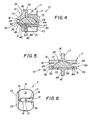
- Figure 6 is a top plan view of the upper part of the implant of Figure 1 ;
- Figure 7 is a perspective view of the bottom surface of the upper part of the implant of Figure 1 ;
- Figure 8 is a bottom plan view of the lower part of the implant of Figure 1 ;
- Figure 9 is a bottom perspective view of the lower part of the implant of Figure 1 ;
- Figure 10 is a top perspective view of the lower part of the implant of Figure 1 ;
- Figure 11 is a top perspective view of the plastic inlay of the implant of Figure 1 ;
- Figure 12 is a top plan view of the plastic inlay of the implant of Figure 1 ;
- Figure 13 is a bottom perspective view of the plastic inlay of the implant of Figure 1 ;
- Figures 14-17 are elevational views of the implant of Figure 1 illustrating the limited universal movement of the parts thereof;
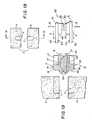
- Figure 18 is a schematic view of a pair of adjacent vertebrae prepared to receive an implant of the present invention in the intervertebral space therebetween;
- Figure 19 illustrates the vertebrae of Figure 18 , in a direction along line 19-19 of Figure 18 and showing the implant itself about to be inserted and showing an insertion tool prior to engaging the implant;
- Figure 20 illustrates a portion of an insertion tool for use with the implant of the present invention
- Figure 21 illustrates the vertebrae of Figure 18 with the implant in place therein and the insertion tool still holding the implant in the same position in which it held the implant during insertion;
- Figure 22 illustrates the vertebrae with the implant in place and the insertion tool removed.
- the words “upper” or “lower” or “uppermost or “lowermost” or any other words describing the orientation of the intervertebral implant of the present invention are used only for convenience and are not intended to convey any limitation. More specifically, the part of the implant described in this application as the upper part can in fact be positioned as the superior or inferior part within the patient's vertebrae with the other of the two parts being the opposite part. Also, since the intervertebral implant is normally inserted from the front of the patient, the side of the vertebrae toward which the intervertebral implant moves as it is inserted shall be referred to as the anterior side of the vertebrae and the opposite side as the posterior side and the right and left sides as lateral sides.
- intervertebral implant can also be inserted laterally, i.e., from the side, in which case the keels will be oriented on the implant for such lateral movement and the cutouts in the adjacent vertebrae will be open toward a lateral side to receive the keel.
- Figures 1-5 illustrate in different views the assembled intervertebral implant 10 including an upper part 11, a lower part 30 and a plastic inlay 50 located therebetween but connected to the lower part 30.
- the intervertebral implant of the present invention has been designed primarily for insertion in the cervical spine. This portion of the spine is characterized by the need for precision because of the relatively small dimensions of the cervical intervertebral space.
- the implant of the present invention when viewed in plan view (as best seen for example in Figure 6 ) would be approximately 12-16 millimeters in width and approximately 15-19 millimeters in length. It has been found practical to provide three sizes, 12 millimeters x 15 millimeters, 14 millimeters x 17 millimeters and 16 millimeters x 19 millimeters.
- the height of the implant meaning the height from the upper surface of the upper part to the lower surface of the lower part, excluding the keels, would normally be between 5 millimeters and 9 millimeters. These dimensions are in contrast to an intervertebral disc to be located in the lumbar area wherein the rectangular portion would have dimensions more on the order of 27 to 30 millimeters-in width, 34 to 39 millimeters in length, and a height of about 10 to 14 millimeters.
- the features of the present invention are equally adaptable for an intervertebral implant of a different size and design for construction in any other part of the spine including the lumbar spine.
- the upper part 11 will now be described in detail with respect to Figures 1-5 which illustrate the assembled implant and Figures 6 and 7 which illustrate only the upper part 11.
- the upper part 11 includes an upper surface 12 which engages and supports the adjacent vertebral surface.
- This upper surface 12 is bounded by edges which are slightly beveled all the way around as shown at 13 with the largest portion of this bevel being along the posterior surface.
- Below the beveled edge 13, the upper part is bounded by a surrounding side wall 14 which has an anterior support cutout 15.
- the keels are shown oriented anterior to posterior with the solid portion of the keels facing posteriorly and the insertion engaging recess structure facing anteriorly.
- a keel 16 which includes a recess 17 formed therein. This recess is opened upwardly and anteriorly. Referring to Figures 4 and 6 , this recess includes an indentation 21 in the base thereof.
- the posterior end of the keel 16 comprises a V-shaped upper bevel 19 and a V-shaped vertical portion 20, providing a front which is "arrow" shaped, as best seen in Figure 6 .
- the purpose of this "arrow" shape is to facilitate insertion of the keel into a cutout formed in the adjacent vertebrae.
- the anterior opening of the recess is flared at 18, which flare serves to anchor the anterior end of the keel 16 in its cutout in the adjacent vertebrae.
- the upper part 11 includes a lower plane inner surface 24 which includes, as best seen in Figure 7 , a raised rim 26 which defines a concave spherical portion 25. As best shown in Figures 4 and 5 , this spherical concave portion 25 will mate with an upper convex surface of the plastic inlay 50.
- the lower part 30 is described with reference to Figures 1-5 and also Figures 8-10 which show isolated views of the lower part 30.
- the lower part 30 includes a lower vertebrae supporting and engaging surface 31 and an inner upper surface 32. As best seen in Figures 2 , 5 and 10 , this lower part includes grooves 33 and 34 formed in the interior side wall thereof beneath surface 32 and above a base surface 38. A substantially flat back wall 35 extends from base surface 38 to upper surface 32. This lower part includes a beveled edge 36 extending around the periphery of the lower surface 31 with a most pronounced bevel at the posterior thereof and a surrounding side wall 39. The purpose of the grooves 33 and 34 is to receive side flanges 53 and 54 of a plastic inlay 50, as shown in Figure 11 and as will be described in greater detail below.
- Lower part 30 includes an anterior support cutout 37.
- a keel 40 rises upwardly (or in the usual orientation, extends downwardly) from the lower surface 31.
- This keel includes a recess 41 which opens downwardly and anteriorly and has a flared anterior entrance to the recess at 42, which flared entrance serves the same function as flared entrance 18 of upper part 11, i.e., to facilitate engagement of the anterior end of the keel within its cutout in the vertebrae.
- the recess 41 opens downwardly and anteriorly and includes an indentation 43.
- the keel 40 includes at its posterior end a V-shaped lower bevel 45 and a V-shaped vertical portion 46 which together provide an "arrow" shape, as best seen in Figure 8 to facilitate insertion of the keel into its cutout formed in the adjacent vertebrae.
- the lower surface of the plastic inlay 50 includes a raised snap-in projection 57.
- a snap-in recess 44 which is adapted to receive the snap-in projection 57 such that the plastic inlay can snap into place but is thereafter prevented from being removed.
- This snap fit is also shown clearly in Figure 4 . It will be noted, however, that while removal would not occur under normal circumstances, in fact it is possible at a subsequent time, by inserting a tool between the base of the lower part and the plastic inlay to pry the plastic inlay out and remove it. This might be useful, for example, if it were decided to insert a new plastic inlay of a different size or if it became necessary to repair the previously inserted plastic inlay.
- the upper and lower parts are made of a suitable material such as titanium, cobalt chromium molybdenum, stainless steel or ceramics.
- the upper surface of the upper part and the lower surface of the lower part as well as the side surfaces of the keels are coated with a porous coating of titanium.
- the porosity of the coating ideally permits vascularization and osteoplast formation with subsequent bony on-growth.
- the plastic inlay 50 is visible in Figures 1-5 . However, for convenience the numerals pointing to details thereof are not included in any of those figures, but instead are provided in Figures 11-13 . It is preferably made of high density polyethylene.
- Figure 11 illustrates the plastic inlay 50 in its position as shown in Figure 1 . It includes a flat upper surface 51 having attached thereto a convex spherical portion 52 which mates with the concave spherical portion 25 of the upper part 11.
- Side flanges 53 and 54 engage the grooves 33 and 34 in the lower part 30.
- a flat posterior wall 55 engages the posterior wall 35 of the lower part.
- the plastic inlay 50 includes a generally flat lower surface 56 which engages the base surface 38 of the lower part and a snap-in projection 57 which is beveled on the posterior side and includes a sharp ledge on the anterior side so as to snap into place in the recess 44 of base surface 38 to the position as best shown in Figure 4 .
- Figures 14-17 illustrate the limited universal movement of the upper and lower parts of the implant relative to each other when inserted in a patient's intervertebral space.
- Figures 14 and 15 both of which view the anterior of the implant, show maximum lateral bending to the left and right, respectively. It will be noted that in each case the raised rim 26 of the upper part 11 engages the inner surface 32 of the lower part 30. In a preferred embodiment, such lateral bending movement is possible for up to approximately 10.5° for the smaller of the three sizes and approximately 8.9° for the two larger sizes, relative to a reference position wherein the keels are aligned vertically.
- Figure 16 which shows a view from the right side of the patient, shows extension movement of the upper part relative to the lower part which is limited by engagement of the rim 26 with the inner surface 32 of the lower part 30.
- Figure 17 which is a view from the patient's left side, shows maximum flexion of the upper part 11 relative to the lower part 30. Flexion is limited by engagement of the rim 26 with the surface 51 of the inlay 50. In preferred embodiments, extension and flexion can occur up to approximately 10.5° for the smaller three sizes and approximately 8.9° for the two larger sizes, relative to a reference position wherein the keels are vertically aligned.
- Figures 18-22 illustrate the insertion of the implant shown in Figures 1-17 and a portion of an insertion tool for use for inserting the implant
- Figure 18 Is an anterior view of a pair of adjacent vertebrae V on opposite sides of a cleaned-out intervertebral space I.
- cutouts C will be formed in the vertebrae V.
- these cutouts start from the anterior of the vertebrae and extend for most but not all of the distance toward the posterior of the vertebrae, intersecting along its entire length with the surface of the vertebrae facing into the intervertebral space.
- FIG 19 illustrates just to the right of the prepared adjacent vertebrae the intervertebral implant assembled in the form as shown in Figures 1-5 .
- an insertion tool 60 which is to be described with respect to Figures 19 and 20 .
- This insertion tool 60 includes an upper arm 61 and a lower arm 71, which arms are arranged to move towards and away from each other as indicated by the arrows B in Figure 19 .
- Various devices can be provided for moving these arms towards and away from each other.
- One such mechanism in the form of a scissors is partially shown at 80 in Figure 20 .
- the upper and lower arms include keel engaging portions 62 and 72 which engage recesses 17 and 41, respectively.
- These arms include towards their outer ends projections 63 and 73 which are constructed to be received in the indentations 21 and 43, respectively. It will be noted that these keel engaging portions 62 and 72 are relatively narrow. In fact, it is contemplated that the entire width of each keel will be approximately 2 millimeters, thus allowing less than 2 millimeters for the actual recesses.
- the arms 61 and 71 also include lateral support surfaces 64 and 74 which, upon engagement of the tool with the implant, will engage the front support cutouts 15 and 37.
- the arms 61 and 71 will be spaced apart from each other just enough for the projections 63 and 73 to clear the bottoms of the recesses 17 and 41 until the projections 63 and 73 reach the indentations 21 and 43, at which time the arms 61 and 71 will be moved towards each other such that the projections 63 and 73 engage within the indentations 21 and 43 and the lateral support surfaces 64 and 74 are engaged within the cutouts 15 and 37.
- abutment surfaces 65 and 75 on the upper arm and lower arm 61 and 71, respectively, will abut each other, thus limiting further movement of the arms 61 and 71 towards each other.
- the insertion tool moves it into the intervertebral space with the keels 16 and 40 entering the cutouts C, while the portions of the upper and lower parts 11 and 30 posterior of the keels extends within the intervertebral space beyond the cutouts C so that upper surface 12 engages the intervertebral surface of the adjacent vertebrae V posterior of and adjacent to the keel 16 and surface 31 of the lower part 30 engages the intervertebral surface of the adjacent lower vertebrae posterior and adjacent to the keel 40.
- the above described engagement of the insertion tool 60 and the implant 10 prior to insertion is the same as shown in Figure 21 , just after insertion.
- the implant firmly grasped by the insertion tool, the implant is inserted anteriorly with the keels leading the way into the cutouts until the proper position has been reached. At this time, naturally some force will have been exerted to distend the adjacent vertebrae from each other, but preferably just enough to allow the implant to be inserted. In fact many professionals prefer to distend the adjacent vertebrae no more than essentially the width between the upper and lower surfaces 12 and 31 and then apply additional external force with a mallet or the like to complete insertion of the implant.
- the arms of the insertion tool are separated just enough to free the projection/indentation engagements from each other, whereupon the insertion tool is removed anteriorly, leaving the implant in place and relieving any previously applied forces applied to distend the adjacent vertebrae from each other, allowing these adjacent vertebrae to rest upon the supporting surfaces 12 and 31 of the implant.
Description
- This invention relates to intervertebral implants, and in particular, to a new and improved intervertebral implant and to and insertion tool for inserting same.
- Historically, whan it was necessary to completely remove a disc from between adjacent vertebrae, the normal remedy was to fuse the adjacent vertebrae together. More recently, there have been important developments in the field of disc replacement, namely disc arthroplasty which involves the insertion of an artificial intervertebral implant into the intervertebral space between adjacent vertebrae and which allows movement of the adjacent vertebrae relative to each other in flexion, extension, lateral bending, axial rotation, and translation, as well as absorbing axial compression.
- One such development is an artificial intervertebral implant as shown in Published Application No.
WO 01/01893, published January 11, 2001 WO 01/19295, published March 22, 2001 - While the intervertebral implant and instruments as shown in these publications represents a substantial improvement in the art, there exists a continuing need for improvements in the field of artificial intervertebral implants.
- One such area in need of further improvements includes intervertebral implants for the intervertebral spaces between adjacent cervical vertebrae. This is because the cervical vertebrae and the dimensions of the intervertebral spaces between them are quite small. For example, the area of the cervical vertebral surfaces facing the adjacent cervical intervertebral spaces may be only about 20 percent of the intervertebral surfaces of the vertebrae in the lumbar region, thereby making this an extremely delicate area in which to insert an intervertebral implant
- The purpose of the present invention is to provide a new and improved intervertebral implant, an insertion tool for inserting same which are highly advantageous in the delicate and difficult area of the cervical spine. It is to be noted, however, that while the present invention has been developed particularly for the cervical spine, the invention is equally applicable for inserting an intervertebral implant at any location in the spine, including the lumbar spine.
- Thus, although the Invention has been developed and is particularly advantageous for the cervical spine, it will be described below more generally as an intervertebral Implant without specifically identifying any particular portion of the spine.
- It is thus an object of the present invention to provide a new and improved intervertebral implant together with an insertion tool for inserting same.
- It is another object of the present invention to provide an insertion tool for inserting the new improved intervertebral implant.
- In accordance with the present invention, there is provided an intervertebral implant having an upper part and a lower part which are operatively engaged for limited universal movement relative to each other. The upper part has a keel which is received in a cutout In the adjacent vertebrae, while the lower part has a keel which is received in a cutout in the other adjacent vertebrae. In accordance with a main feature of the present invention, these keels, in addition to providing an anchoring function within the adjacent vertebrae, include a recess open at an end thereof for receiving arms of an insertion tool. This has the advantage of allowing grasping the implant firmly but over a very limited area for inserting the implant into the intervertebral space with minimal invasion of the work area by the insertion tool.
- The upper part preferably has a spherical concave portion formed in its lower surface. The lower part preferably has a plastic inlay attached thereto, which inlay has a raised spherical convex portion which engages the spherical concave portion of the upper part to provide the limited universal movement between the two.
- The insertion tool usable in combination with the implant preferably has a pair of arms, each of which engages a recess within a keel, each arm having a projection which is moved toward the base of the recess to engage indentations in the base of the recesses to firmly hold the implant. The arms also include lateral support portions which engage support cutouts on the upper and lower parts to absorb lateral forces exerted on the implant so that such lateral forces do not have to be absorbed by the more delicate portions of the insertion tool arms located within the recesses of the keels.
- Thus, it is an object of the present invention to provide a new and improved intervertebral implant.
- It is another object of the present invention to provide an insertion tool for inserting the new improved intervertebral implant
- It is another object of the present invention to provide an intervertebral implant which is particularly suitable for the cervical spine.
- It is another object of the present invention to provide a new and improved intervertebral implant characterized by a recess in raised keels for receiving insertion tools for inserting the intervertebral implant.
- These and other objects of the present invention will be apparent from the detailed description to follow, together with the accompanying drawings,
- A preferred embodiment of the invention will now be described by way of example with reference to the accompanying drawings, wherein: .
-
Figure 1 is a perspective view of an intervertebral implant in accordance with the present invention; -
Figure 2 is a front elevational view of the implant ofFigure 1 ; -
Figure 3 is a left side elevational view of the implant ofFigure 1 ; -
Figure 4 is a cross sectional view taken along line 4-4 ofFigure 2 ; -
Figure 5 is a cross sectional view taken along line 5-5 ofFigure 3 ; -
Figure 6 is a top plan view of the upper part of the implant ofFigure 1 ; -
Figure 7 is a perspective view of the bottom surface of the upper part of the implant ofFigure 1 ; -
Figure 8 is a bottom plan view of the lower part of the implant ofFigure 1 ; -
Figure 9 is a bottom perspective view of the lower part of the implant ofFigure 1 ; -
Figure 10 is a top perspective view of the lower part of the implant ofFigure 1 ; -
Figure 11 is a top perspective view of the plastic inlay of the implant ofFigure 1 ; -
Figure 12 is a top plan view of the plastic inlay of the implant ofFigure 1 ; -
Figure 13 is a bottom perspective view of the plastic inlay of the implant ofFigure 1 ; -
Figures 14-17 are elevational views of the implant ofFigure 1 illustrating the limited universal movement of the parts thereof; -
Figure 18 is a schematic view of a pair of adjacent vertebrae prepared to receive an implant of the present invention in the intervertebral space therebetween; -
Figure 19 illustrates the vertebrae ofFigure 18 , in a direction along line 19-19 ofFigure 18 and showing the implant itself about to be inserted and showing an insertion tool prior to engaging the implant; -
Figure 20 illustrates a portion of an insertion tool for use with the implant of the present invention; -
Figure 21 illustrates the vertebrae ofFigure 18 with the implant in place therein and the insertion tool still holding the implant in the same position in which it held the implant during insertion; and -
Figure 22 illustrates the vertebrae with the implant in place and the insertion tool removed. - Referring now to the figures, like elements are represented by like numerals throughout the several views.
- In this application, the words "upper" or "lower" or "uppermost or "lowermost" or any other words describing the orientation of the intervertebral implant of the present invention are used only for convenience and are not intended to convey any limitation. More specifically, the part of the implant described in this application as the upper part can in fact be positioned as the superior or inferior part within the patient's vertebrae with the other of the two parts being the opposite part. Also, since the intervertebral implant is normally inserted from the front of the patient, the side of the vertebrae toward which the intervertebral implant moves as it is inserted shall be referred to as the anterior side of the vertebrae and the opposite side as the posterior side and the right and left sides as lateral sides. Since the more common manner of insertion is anteriorly, the present invention will be described with respect to that orientation. However, it is to be understood that the intervertebral implant can also be inserted laterally, i.e., from the side, in which case the keels will be oriented on the implant for such lateral movement and the cutouts in the adjacent vertebrae will be open toward a lateral side to receive the keel.
-
Figures 1-5 illustrate in different views the assembledintervertebral implant 10 including anupper part 11, alower part 30 and aplastic inlay 50 located therebetween but connected to thelower part 30. - The intervertebral implant of the present invention has been designed primarily for insertion in the cervical spine. This portion of the spine is characterized by the need for precision because of the relatively small dimensions of the cervical intervertebral space. For example, the implant of the present invention, when viewed in plan view (as best seen for example in
Figure 6 ) would be approximately 12-16 millimeters in width and approximately 15-19 millimeters in length. It has been found practical to provide three sizes, 12 millimeters x 15 millimeters, 14 millimeters x 17 millimeters and 16 millimeters x 19 millimeters. The height of the implant, meaning the height from the upper surface of the upper part to the lower surface of the lower part, excluding the keels, would normally be between 5 millimeters and 9 millimeters. These dimensions are in contrast to an intervertebral disc to be located in the lumbar area wherein the rectangular portion would have dimensions more on the order of 27 to 30 millimeters-in width, 34 to 39 millimeters in length, and a height of about 10 to 14 millimeters. However, it is to be understood that the features of the present invention are equally adaptable for an intervertebral implant of a different size and design for construction in any other part of the spine including the lumbar spine. - The
upper part 11 will now be described in detail with respect toFigures 1-5 which illustrate the assembled implant andFigures 6 and7 which illustrate only theupper part 11. Theupper part 11 includes anupper surface 12 which engages and supports the adjacent vertebral surface. Thisupper surface 12 is bounded by edges which are slightly beveled all the way around as shown at 13 with the largest portion of this bevel being along the posterior surface. Below thebeveled edge 13, the upper part is bounded by a surroundingside wall 14 which has ananterior support cutout 15. Thus, in the figures the keels are shown oriented anterior to posterior with the solid portion of the keels facing posteriorly and the insertion engaging recess structure facing anteriorly. - Rising above the
upper surface 12 of theupper part 11 is akeel 16 which includes arecess 17 formed therein. This recess is opened upwardly and anteriorly. Referring toFigures 4 and 6 , this recess includes anindentation 21 in the base thereof. The posterior end of thekeel 16 comprises a V-shapedupper bevel 19 and a V-shapedvertical portion 20, providing a front which is "arrow" shaped, as best seen inFigure 6 . The purpose of this "arrow" shape is to facilitate insertion of the keel into a cutout formed in the adjacent vertebrae. The anterior opening of the recess is flared at 18, which flare serves to anchor the anterior end of thekeel 16 in its cutout in the adjacent vertebrae. - The
upper part 11 includes a lower planeinner surface 24 which includes, as best seen inFigure 7 , a raisedrim 26 which defines a concavespherical portion 25. As best shown inFigures 4 and 5 , this sphericalconcave portion 25 will mate with an upper convex surface of theplastic inlay 50. - The
lower part 30 is described with reference toFigures 1-5 and alsoFigures 8-10 which show isolated views of thelower part 30. - The
lower part 30 includes a lower vertebrae supporting and engagingsurface 31 and an innerupper surface 32. As best seen inFigures 2 ,5 and10 , this lower part includesgrooves surface 32 and above abase surface 38. A substantiallyflat back wall 35 extends frombase surface 38 toupper surface 32. This lower part includes abeveled edge 36 extending around the periphery of thelower surface 31 with a most pronounced bevel at the posterior thereof and asurrounding side wall 39. The purpose of thegrooves side flanges plastic inlay 50, as shown inFigure 11 and as will be described in greater detail below. -
Lower part 30 includes ananterior support cutout 37. Akeel 40 rises upwardly (or in the usual orientation, extends downwardly) from thelower surface 31. This keel includes arecess 41 which opens downwardly and anteriorly and has a flared anterior entrance to the recess at 42, which flared entrance serves the same function as flaredentrance 18 ofupper part 11, i.e., to facilitate engagement of the anterior end of the keel within its cutout in the vertebrae. As best shown inFigure 4 , therecess 41 opens downwardly and anteriorly and includes anindentation 43. Thekeel 40 includes at its posterior end a V-shapedlower bevel 45 and a V-shapedvertical portion 46 which together provide an "arrow" shape, as best seen inFigure 8 to facilitate insertion of the keel into its cutout formed in the adjacent vertebrae. - Referring momentarily to
Figure 13 , it will be noted that the lower surface of theplastic inlay 50 includes a raised snap-inprojection 57. Referring now toFigure 10 , there is illustrated a snap-inrecess 44 which is adapted to receive the snap-inprojection 57 such that the plastic inlay can snap into place but is thereafter prevented from being removed. This snap fit is also shown clearly inFigure 4 . It will be noted, however, that while removal would not occur under normal circumstances, in fact it is possible at a subsequent time, by inserting a tool between the base of the lower part and the plastic inlay to pry the plastic inlay out and remove it. This might be useful, for example, if it were decided to insert a new plastic inlay of a different size or if it became necessary to repair the previously inserted plastic inlay. - The upper and lower parts are made of a suitable material such as titanium, cobalt chromium molybdenum, stainless steel or ceramics. The upper surface of the upper part and the lower surface of the lower part as well as the side surfaces of the keels are coated with a porous coating of titanium. The porosity of the coating ideally permits vascularization and osteoplast formation with subsequent bony on-growth.
- The
plastic inlay 50 is visible inFigures 1-5 . However, for convenience the numerals pointing to details thereof are not included in any of those figures, but instead are provided inFigures 11-13 . It is preferably made of high density polyethylene.Figure 11 illustrates theplastic inlay 50 in its position as shown inFigure 1 . It includes a flatupper surface 51 having attached thereto a convexspherical portion 52 which mates with the concavespherical portion 25 of theupper part 11.Side flanges grooves lower part 30. Aflat posterior wall 55 engages theposterior wall 35 of the lower part. - Referring to
Figure 13 , theplastic inlay 50 includes a generally flatlower surface 56 which engages thebase surface 38 of the lower part and a snap-inprojection 57 which is beveled on the posterior side and includes a sharp ledge on the anterior side so as to snap into place in therecess 44 ofbase surface 38 to the position as best shown inFigure 4 . -
Figures 14-17 illustrate the limited universal movement of the upper and lower parts of the implant relative to each other when inserted in a patient's intervertebral space.Figures 14 and 15 , both of which view the anterior of the implant, show maximum lateral bending to the left and right, respectively. It will be noted that in each case the raisedrim 26 of theupper part 11 engages theinner surface 32 of thelower part 30. In a preferred embodiment, such lateral bending movement is possible for up to approximately 10.5° for the smaller of the three sizes and approximately 8.9° for the two larger sizes, relative to a reference position wherein the keels are aligned vertically.Figure 16 , which shows a view from the right side of the patient, shows extension movement of the upper part relative to the lower part which is limited by engagement of therim 26 with theinner surface 32 of thelower part 30. Finally,Figure 17 , which is a view from the patient's left side, shows maximum flexion of theupper part 11 relative to thelower part 30. Flexion is limited by engagement of therim 26 with thesurface 51 of theinlay 50. In preferred embodiments, extension and flexion can occur up to approximately 10.5° for the smaller three sizes and approximately 8.9° for the two larger sizes, relative to a reference position wherein the keels are vertically aligned. -
Figures 18-22 illustrate the insertion of the implant shown inFigures 1-17 and a portion of an insertion tool for use for inserting the implant -
Figure 18 Is an anterior view of a pair of adjacent vertebrae V on opposite sides of a cleaned-out intervertebral space I. In preparation for inserting the intervertebral implant of the present invention, cutouts C will be formed in the vertebrae V. As shown inFigure 18 and the left hand portion ofFigure 19 , these cutouts start from the anterior of the vertebrae and extend for most but not all of the distance toward the posterior of the vertebrae, intersecting along its entire length with the surface of the vertebrae facing into the intervertebral space. -
Figure 19 illustrates just to the right of the prepared adjacent vertebrae the intervertebral implant assembled in the form as shown inFigures 1-5 . To the right thereof is aninsertion tool 60 which is to be described with respect toFigures 19 and20 . Thisinsertion tool 60 includes anupper arm 61 and alower arm 71, which arms are arranged to move towards and away from each other as indicated by the arrows B inFigure 19 . Various devices can be provided for moving these arms towards and away from each other. One such mechanism in the form of a scissors is partially shown at 80 inFigure 20 . The upper and lower arms includekeel engaging portions outer ends projections indentations keel engaging portions arms front support cutouts - The
arms projections recesses projections indentations arms projections indentations cutouts lower arm arms - With the assembled implant thus attached to the insertion tool, the insertion tool moves it into the intervertebral space with the
keels lower parts upper surface 12 engages the intervertebral surface of the adjacent vertebrae V posterior of and adjacent to thekeel 16 andsurface 31 of thelower part 30 engages the intervertebral surface of the adjacent lower vertebrae posterior and adjacent to thekeel 40. Actually, the above described engagement of theinsertion tool 60 and theimplant 10 prior to insertion is the same as shown inFigure 21 , just after insertion. - It will be noted that in
Figure 21 there is a space above and below thearms projection arms arms Figure 22 . implant firmly grasped by the insertion tool, the implant is inserted anteriorly with the keels leading the way into the cutouts until the proper position has been reached. At this time, naturally some force will have been exerted to distend the adjacent vertebrae from each other, but preferably just enough to allow the implant to be inserted. In fact many professionals prefer to distend the adjacent vertebrae no more than essentially the width between the upper andlower surfaces surfaces - Although the invention has been described in detail with respect to preferred embodiments thereof, it will be apparent to one skilled in the art that the invention is capable of numerous modifications and variations within the scope of the invention.
Claims (13)
- An intervertebral implant (10) comprising an upper part (11) adapted to engage an adjacent vertebrae and a lower part (30) adapted to engage an adjacent vertebrae, the upper and lower parts (11,30) being in operative contact with each other so as to allow them limited lateral bending and flexing/extending movement relative to each other,
each of the upper and lower parts (111,30) having a raised keel (16,42) on its surface (12,31) for engaging the adjacent vertebrae, which keel (16,42) is adapted to be received within its adjacent vertebrae through a cutout formed in the anterior of that vertebrae, characterized in that
each keel (16,42) has a recess (17,41) and a base with an indentation (21,43) therein, which recess (17, 41) has an anterior opening, for receiving an insertion tool (60) for inserting the implant (10) into the intervertebral space. - An implant according to claim 1, wherein said indentation (21,43) is for engaging said insertion tool (60) to secure the tool (60) against movement out of the recess.
- An implant (10) according to claim 2, wherein the indentations (21 ,43) are formed in the base of the recesses (17,41) closest to the implant (10) and adapted to receive a projection (63,73) on the insertion tool (60).
- An implant (10) according to claim 1, wherein the keels (16,42) are beveled on the posterior ends thereof to facilitate entry of the keel (16,42) into the cutout
- An implant (10) according to claim 1, wherein the keels (16,42) are flared outwardly adjacent the anterior openings to facilitate the keel (16,42) engaging the anterior of the vertebrae adjacent the cutout
- An implant (10) according to claim 1, the implant (10) comprising a lower part (30) having a plastic inlay (50) attached thereto with an upwardly spherical convex portion (52) and the upper part (11) having a concave spherical portion (25) in an operative engagement with the spherical convex portion (52).
- An implant according to claim 6, the plastic inlay (50) being snap fitted into the lower part (30).
- An implant according to claim 1, wherein the upper and lower parts (11,30) have anterior support cutouts (15,37) adjacent the anterior keel recess openings for receiving a portion of the insertion tool (60).
- Intervertebral implant (10) and an insertion tool (60) for inserting same, the implant (10) comprising an upper part (11) adapted to engage an adjacent vertebrae and a lower part (30) adapted to engage an adjacent vertebrae, the upper and lower parts (11,30) being in operative contact with each other so as to allow them limited lateral bending and flexing/extending movement relative to each other,
each of the upper and lower parts (11,30) having a raised keel (16,42) on its surface (12,31) engaging the adjacent vertebrae, which keel (16,42) is adapted to be received within its adjacent vertebrae through a cutout formed in the anterior of that vertebrae, characterized in that
each keel (16,42) has a recess (17,41) and a base with an indentation (21, 43), which recess (17, 41) has an anterior opening,
and said insertion tool (60) having a pair of arms (61,71), wherein the arms (61,71) have a projection (63,73) to complementarily engage the indentations (21,43) in the base of the recesses (17,41), one arm (61,71) engaging each recess (17,41) through the anterior opening thereof, to thereby grasp the implant (10) for insertion into the intervertebral space. - The invention according to claim 9, wherein the upper and lower parts (11,30) each have a front support cutout (15,37) adjacent the keel recess opening for receiving a portion of the insertion tool (60), said arms (61,71) having a first narrow portion for insertion into the recess (17,41) of its respective keel (16,42) and a second broader portion for engaging the front support cutouts (15,37).
- The invention according to claim 9, wherein the insertion tools (60) are movable in a direction into and out of their respective recesses (17,41), through the rear opening, and in a direction perpendicular thereto to engage and release their respective implants (10).
- The invention according to claim 11, said insertion tools (60) having abutment surfaces (65,75) which abut each other to limit movement of the two arms (61,71) towards each other.
- The invention according to claim 11, wherein the height of each arm (61,71) is less than the height of the recess (17,41) in which it is received by an amount greater than the height of its projection (63,73) to thereby allow vertical movement of the projection (63,73) out of its indentation (21,43) without the arm (61,71) moving upwardly out of its recess (17,41).
Applications Claiming Priority (3)
| Application Number | Priority Date | Filing Date | Title |
|---|---|---|---|
| US318078 | 2002-12-13 | ||
| US10/318,078 US7204852B2 (en) | 2002-12-13 | 2002-12-13 | Intervertebral implant, insertion tool and method of inserting same |
| PCT/US2003/039056 WO2004054480A1 (en) | 2002-12-13 | 2003-12-10 | Intervertebral implant, insertion tool and method of inserting same |
Publications (3)
| Publication Number | Publication Date |
|---|---|
| EP1572041A1 EP1572041A1 (en) | 2005-09-14 |
| EP1572041A4 EP1572041A4 (en) | 2006-01-25 |
| EP1572041B1 true EP1572041B1 (en) | 2010-04-14 |
Family
ID=32506284
Family Applications (1)
| Application Number | Title | Priority Date | Filing Date |
|---|---|---|---|
| EP03813356A Expired - Lifetime EP1572041B1 (en) | 2002-12-13 | 2003-12-10 | Intervertebral implant and insertion tool for inserting same |
Country Status (14)
| Country | Link |
|---|---|
| US (6) | US7204852B2 (en) |
| EP (1) | EP1572041B1 (en) |
| JP (1) | JP4463110B2 (en) |
| KR (1) | KR101102318B1 (en) |
| CN (1) | CN1725989B (en) |
| AR (1) | AR042460A1 (en) |
| AT (1) | ATE464029T1 (en) |
| AU (1) | AU2003300834B2 (en) |
| BR (1) | BRPI0317184B8 (en) |
| CA (1) | CA2509823C (en) |
| DE (1) | DE60332152D1 (en) |
| ES (1) | ES2344694T3 (en) |
| WO (1) | WO2004054480A1 (en) |
| ZA (1) | ZA200504427B (en) |
Cited By (1)
| Publication number | Priority date | Publication date | Assignee | Title |
|---|---|---|---|---|
| US8579978B2 (en) | 2002-12-13 | 2013-11-12 | DePuy Synthes Products, LLC | Intervertebral implant, insertion tool and method of inserting same |
Families Citing this family (256)
| Publication number | Priority date | Publication date | Assignee | Title |
|---|---|---|---|---|
| US20080215058A1 (en) * | 1997-01-02 | 2008-09-04 | Zucherman James F | Spine distraction implant and method |
| ATE388677T1 (en) | 1999-07-02 | 2008-03-15 | Spine Solutions Inc | INTERVERBARY IMPLANT |
| FR2897259B1 (en) * | 2006-02-15 | 2008-05-09 | Ldr Medical Soc Par Actions Si | INTERSOMATIC TRANSFORAMINAL CAGE WITH INTERBREBAL FUSION GRAFT AND CAGE IMPLANTATION INSTRUMENT |
| DE59914213D1 (en) | 1999-09-14 | 2007-04-05 | Spine Solutions Inc | INSERT INSTRUMENT FOR A INTERMEDIATE IMPLANT |
| US6673113B2 (en) | 2001-10-18 | 2004-01-06 | Spinecore, Inc. | Intervertebral spacer device having arch shaped spring elements |
| US7169182B2 (en) * | 2001-07-16 | 2007-01-30 | Spinecore, Inc. | Implanting an artificial intervertebral disc |
| FR2824261B1 (en) * | 2001-05-04 | 2004-05-28 | Ldr Medical | INTERVERTEBRAL DISC PROSTHESIS AND IMPLEMENTATION METHOD AND TOOLS |
| FR2827156B1 (en) | 2001-07-13 | 2003-11-14 | Ldr Medical | VERTEBRAL CAGE DEVICE WITH MODULAR FASTENING |
| US7771477B2 (en) | 2001-10-01 | 2010-08-10 | Spinecore, Inc. | Intervertebral spacer device utilizing a belleville washer having radially spaced concentric grooves |
| US7713302B2 (en) | 2001-10-01 | 2010-05-11 | Spinecore, Inc. | Intervertebral spacer device utilizing a spirally slotted belleville washer having radially spaced concentric grooves |
| FR2831049B1 (en) * | 2001-10-18 | 2004-08-13 | Ldr Medical | PLATE FOR OSTEOSYNTHESIS DEVICE AND PRE-ASSEMBLY METHOD |
| FR2831048B1 (en) | 2001-10-18 | 2004-09-17 | Ldr Medical | PROGRESSIVE APPROACH OSTEOSYNTHESIS DEVICE AND PRE-ASSEMBLY PROCESS |
| US6824278B2 (en) * | 2002-03-15 | 2004-11-30 | Memx, Inc. | Self-shadowing MEM structures |
| CA2451147C (en) * | 2002-04-05 | 2013-07-30 | Nippon Steel Corporation | Pearlitic steel rail excellent in wear resistance and ductility and method for producing the same |
| US20080027548A9 (en) | 2002-04-12 | 2008-01-31 | Ferree Bret A | Spacerless artificial disc replacements |
| US8038713B2 (en) | 2002-04-23 | 2011-10-18 | Spinecore, Inc. | Two-component artificial disc replacements |
| US6706068B2 (en) | 2002-04-23 | 2004-03-16 | Bret A. Ferree | Artificial disc replacements with natural kinematics |
| US7001433B2 (en) * | 2002-05-23 | 2006-02-21 | Pioneer Laboratories, Inc. | Artificial intervertebral disc device |
| US8388684B2 (en) | 2002-05-23 | 2013-03-05 | Pioneer Signal Technology, Inc. | Artificial disc device |
| US6793678B2 (en) | 2002-06-27 | 2004-09-21 | Depuy Acromed, Inc. | Prosthetic intervertebral motion disc having dampening |
| WO2004016217A2 (en) * | 2002-08-15 | 2004-02-26 | David Gerber | Controlled artificial intervertebral disc implant |
| WO2004026186A1 (en) * | 2002-09-18 | 2004-04-01 | Mathys Medizinaltechnik Ag | Implant comprising a two-piece joint |
| US7833246B2 (en) | 2002-10-29 | 2010-11-16 | Kyphon SÀRL | Interspinous process and sacrum implant and method |
| US7497859B2 (en) * | 2002-10-29 | 2009-03-03 | Kyphon Sarl | Tools for implanting an artificial vertebral disk |
| US6966929B2 (en) * | 2002-10-29 | 2005-11-22 | St. Francis Medical Technologies, Inc. | Artificial vertebral disk replacement implant with a spacer |
| FR2846550B1 (en) | 2002-11-05 | 2006-01-13 | Ldr Medical | INTERVERTEBRAL DISC PROSTHESIS |
| GB0301085D0 (en) * | 2003-01-17 | 2003-02-19 | Krishna Manoj | Articulating spinal disc prosthesis |
| US20040158254A1 (en) * | 2003-02-12 | 2004-08-12 | Sdgi Holdings, Inc. | Instrument and method for milling a path into bone |
| AU2004212942A1 (en) | 2003-02-14 | 2004-09-02 | Depuy Spine, Inc. | In-situ formed intervertebral fusion device |
| US20040176853A1 (en) * | 2003-03-05 | 2004-09-09 | Sennett Andrew R. | Apparatus and method for spinal fusion using posteriorly implanted devices |
| AU2004220634B2 (en) * | 2003-03-06 | 2009-09-17 | Spinecore, Inc. | Instrumentation and methods for use in implanting a cervical disc replacement device |
| US6908484B2 (en) | 2003-03-06 | 2005-06-21 | Spinecore, Inc. | Cervical disc replacement |
| US7771478B2 (en) * | 2003-04-04 | 2010-08-10 | Theken Spine, Llc | Artificial disc prosthesis |
| US7491204B2 (en) | 2003-04-28 | 2009-02-17 | Spine Solutions, Inc. | Instruments and method for preparing an intervertebral space for receiving an artificial disc implant |
| WO2004098466A2 (en) * | 2003-05-02 | 2004-11-18 | Smart Disc, Inc. | Artificial spinal disk |
| US7105024B2 (en) | 2003-05-06 | 2006-09-12 | Aesculap Ii, Inc. | Artificial intervertebral disc |
| US7291173B2 (en) | 2003-05-06 | 2007-11-06 | Aesculap Ii, Inc. | Artificial intervertebral disc |
| US20040267367A1 (en) | 2003-06-30 | 2004-12-30 | Depuy Acromed, Inc | Intervertebral implant with conformable endplate |
| DE20310433U1 (en) * | 2003-07-08 | 2003-09-04 | Aesculap Ag & Co Kg | Surgical device for inserting dual component implant into appropriate space at spine, comprising particularly shaped holding area |
| DE10330698B4 (en) * | 2003-07-08 | 2005-05-25 | Aesculap Ag & Co. Kg | Intervertebral implant |
| US7803162B2 (en) * | 2003-07-21 | 2010-09-28 | Spine Solutions, Inc. | Instruments and method for inserting an intervertebral implant |
| US7722673B2 (en) * | 2003-07-22 | 2010-05-25 | Cervitech, Inc. | Intervertebral disc prosthesis |
| WO2005007041A1 (en) * | 2003-07-22 | 2005-01-27 | Synthes Gmbh | Intervertebral implant comprising temporary blocking means |
| US7713304B2 (en) * | 2003-07-31 | 2010-05-11 | Globus Medical, Inc. | Transforaminal prosthetic spinal disc replacement |
| US7811329B2 (en) * | 2003-07-31 | 2010-10-12 | Globus Medical | Transforaminal prosthetic spinal disc replacement and methods thereof |
| US9844442B2 (en) * | 2003-07-31 | 2017-12-19 | Globus Medical, Inc. | Prosthetic spinal disc replacement and methods thereof |
| US7621956B2 (en) * | 2003-07-31 | 2009-11-24 | Globus Medical, Inc. | Prosthetic spinal disc replacement |
| US7153325B2 (en) * | 2003-08-01 | 2006-12-26 | Ultra-Kinetics, Inc. | Prosthetic intervertebral disc and methods for using the same |
| FR2858546B1 (en) * | 2003-08-04 | 2006-04-28 | Spine Next Sa | INTERVERTEBRAL DISC PROSTHESIS |
| US7753958B2 (en) | 2003-08-05 | 2010-07-13 | Gordon Charles R | Expandable intervertebral implant |
| DE10339170B4 (en) * | 2003-08-22 | 2009-10-15 | Aesculap Ag | Intervertebral implant |
| ATE390101T1 (en) * | 2003-11-18 | 2008-04-15 | Zimmer Gmbh | DISC IMPLANT |
| US7837732B2 (en) | 2003-11-20 | 2010-11-23 | Warsaw Orthopedic, Inc. | Intervertebral body fusion cage with keels and implantation methods |
| US20050149192A1 (en) * | 2003-11-20 | 2005-07-07 | St. Francis Medical Technologies, Inc. | Intervertebral body fusion cage with keels and implantation method |
| US7670377B2 (en) | 2003-11-21 | 2010-03-02 | Kyphon Sarl | Laterally insertable artifical vertebral disk replacement implant with curved spacer |
| US20050154462A1 (en) * | 2003-12-02 | 2005-07-14 | St. Francis Medical Technologies, Inc. | Laterally insertable artificial vertebral disk replacement implant with translating pivot point |
| FR2865629B1 (en) | 2004-02-04 | 2007-01-26 | Ldr Medical | INTERVERTEBRAL DISC PROSTHESIS |
| ES2547532T3 (en) | 2004-02-04 | 2015-10-07 | Ldr Medical | Intervertebral disc prosthesis |
| WO2005077013A2 (en) | 2004-02-06 | 2005-08-25 | Georgia Tech Research Corporation | Surface directed cellular attachment |
| US7910124B2 (en) | 2004-02-06 | 2011-03-22 | Georgia Tech Research Corporation | Load bearing biocompatible device |
| US7367979B2 (en) * | 2004-02-27 | 2008-05-06 | Custom Spine, Inc. | Screwdriver |
| FR2869528B1 (en) * | 2004-04-28 | 2007-02-02 | Ldr Medical | INTERVERTEBRAL DISC PROSTHESIS |
| US7500972B2 (en) * | 2004-05-07 | 2009-03-10 | Ethicon Endo-Surgery, Inc. | Device for alternately holding, or effecting relative longitudinal movement, of members of a medical instrument |
| US9237958B2 (en) * | 2004-06-30 | 2016-01-19 | Synergy Disc Replacement Inc. | Joint prostheses |
| US8172904B2 (en) * | 2004-06-30 | 2012-05-08 | Synergy Disc Replacement, Inc. | Artificial spinal disc |
| EP2641571B1 (en) * | 2004-06-30 | 2016-04-13 | Synergy Disc Replacement Inc. | Artificial spinal disc |
| US20060009541A1 (en) * | 2004-07-09 | 2006-01-12 | Yih-Fang Chen | Saturant for friction material containing friction modifying layer |
| US7594919B2 (en) * | 2004-07-23 | 2009-09-29 | Warsaw Orthopedic, Inc. | Artificial disc inserter |
| US7294134B2 (en) * | 2004-07-28 | 2007-11-13 | Weber Instrumente Gmbh | Surgical instrument for the introduction of a multi-component intervertebral prosthesis |
| US7585326B2 (en) * | 2004-08-06 | 2009-09-08 | Spinalmotion, Inc. | Methods and apparatus for intervertebral disc prosthesis insertion |
| US8470004B2 (en) | 2004-08-09 | 2013-06-25 | Si-Bone Inc. | Apparatus, systems, and methods for stabilizing a spondylolisthesis |
| US8388667B2 (en) * | 2004-08-09 | 2013-03-05 | Si-Bone, Inc. | Systems and methods for the fixation or fusion of bone using compressive implants |
| US8414648B2 (en) | 2004-08-09 | 2013-04-09 | Si-Bone Inc. | Apparatus, systems, and methods for achieving trans-iliac lumbar fusion |
| US9949843B2 (en) | 2004-08-09 | 2018-04-24 | Si-Bone Inc. | Apparatus, systems, and methods for the fixation or fusion of bone |
| US8425570B2 (en) | 2004-08-09 | 2013-04-23 | Si-Bone Inc. | Apparatus, systems, and methods for achieving anterior lumbar interbody fusion |
| US9662158B2 (en) | 2004-08-09 | 2017-05-30 | Si-Bone Inc. | Systems and methods for the fixation or fusion of bone at or near a sacroiliac joint |
| US20070156241A1 (en) | 2004-08-09 | 2007-07-05 | Reiley Mark A | Systems and methods for the fixation or fusion of bone |
| US20180228621A1 (en) | 2004-08-09 | 2018-08-16 | Mark A. Reiley | Apparatus, systems, and methods for the fixation or fusion of bone |
| US20060036251A1 (en) | 2004-08-09 | 2006-02-16 | Reiley Mark A | Systems and methods for the fixation or fusion of bone |
| US8444693B2 (en) * | 2004-08-09 | 2013-05-21 | Si-Bone Inc. | Apparatus, systems, and methods for achieving lumbar facet fusion |
| US20060041313A1 (en) * | 2004-08-19 | 2006-02-23 | Sdgi Holdings, Inc. | Intervertebral disc system |
| JP2006068086A (en) * | 2004-08-31 | 2006-03-16 | Takiron Co Ltd | Artificial spinal disk insertion tool and tool set |
| NZ554608A (en) * | 2004-09-23 | 2010-07-30 | Spine Solutions Inc | System and method for an intervertebral implant |
| US7763024B2 (en) * | 2004-09-23 | 2010-07-27 | Spine Solutions, Inc. | Adjustable cutting of cutout in vertebral bone |
| US20060085076A1 (en) * | 2004-10-15 | 2006-04-20 | Manoj Krishna | Posterior spinal arthroplasty-development of a new posteriorly inserted artificial disc and an artificial facet joint |
| WO2006042486A1 (en) * | 2004-10-18 | 2006-04-27 | Buettner-Janz Karin | Intervertebral disk endoprosthesis having a motion-adapted edge for the lumbar and cervical spine |
| WO2006042485A1 (en) * | 2004-10-18 | 2006-04-27 | Buettner-Janz Karin | Intervertebral disk endoprosthesis for lumbar and cervical spine, which corresponds to the physiology of movement |
| WO2006042484A1 (en) * | 2004-10-18 | 2006-04-27 | Buettner-Janz Karin | Bent sliding core as part of an intervertebral disk endoprosthesis |
| US20060265074A1 (en) | 2004-10-21 | 2006-11-23 | Manoj Krishna | Posterior spinal arthroplasty-development of a new posteriorly inserted artificial disc, a new anteriorly inserted artifical disc and an artificial facet joint |
| ATE524121T1 (en) | 2004-11-24 | 2011-09-15 | Abdou Samy | DEVICES FOR PLACING AN ORTHOPEDIC INTERVERTEBRAL IMPLANT |
| FR2879436B1 (en) | 2004-12-22 | 2007-03-09 | Ldr Medical | INTERVERTEBRAL DISC PROSTHESIS |
| US8579911B2 (en) | 2008-01-18 | 2013-11-12 | Spinecore, Inc. | Instruments and methods for inserting artificial intervertebral implants |
| US8777959B2 (en) | 2005-05-27 | 2014-07-15 | Spinecore, Inc. | Intervertebral disc and insertion methods therefor |
| US8394142B2 (en) * | 2005-06-13 | 2013-03-12 | Synthes Usa, Llc | Customizing an intervertebral implant |
| FR2887762B1 (en) * | 2005-06-29 | 2007-10-12 | Ldr Medical Soc Par Actions Si | INTERVERTEBRAL DISC PROSTHESIS INSERTION INSTRUMENTATION BETWEEN VERTEBRATES |
| US20070050032A1 (en) * | 2005-09-01 | 2007-03-01 | Spinal Kinetics, Inc. | Prosthetic intervertebral discs |
| FR2891135B1 (en) | 2005-09-23 | 2008-09-12 | Ldr Medical Sarl | INTERVERTEBRAL DISC PROSTHESIS |
| US20070093900A1 (en) * | 2005-09-26 | 2007-04-26 | Williams Lytton A | Modular articulating and fusion spinal disc implant system |
| US7927373B2 (en) | 2005-10-31 | 2011-04-19 | Depuy Spine, Inc. | Intervertebral disc prosthesis |
| FR2893838B1 (en) | 2005-11-30 | 2008-08-08 | Ldr Medical Soc Par Actions Si | PROSTHESIS OF INTERVERTEBRAL DISC AND INSTRUMENTATION OF INSERTION OF THE PROSTHESIS BETWEEN VERTEBRATES |
| US7867279B2 (en) * | 2006-01-23 | 2011-01-11 | Depuy Spine, Inc. | Intervertebral disc prosthesis |
| US8038920B2 (en) * | 2006-01-25 | 2011-10-18 | Carticept Medical, Inc. | Methods of producing PVA hydrogel implants and related devices |
| US20070173941A1 (en) * | 2006-01-25 | 2007-07-26 | Sdgi Holdings, Inc. | Intervertebral prosthetic disc and method of installing same |
| US8603171B2 (en) * | 2006-01-25 | 2013-12-10 | Mimedx Group, Inc. | Spinal disc implants with flexible keels and methods of fabricating implants |
| US7708777B2 (en) * | 2006-02-03 | 2010-05-04 | Depuy Spine, Inc. | Modular intervertebral disc replacements |
| US20070198093A1 (en) * | 2006-02-17 | 2007-08-23 | Amedica Corporation | Spinal implant with offset keels |
| US7875034B2 (en) * | 2006-03-14 | 2011-01-25 | Warsaw Orthopedic, Inc. | Spinal disc space preparation instruments and methods for interbody spinal implants |
| US8043379B2 (en) * | 2006-04-21 | 2011-10-25 | Depuy Spine, Inc. | Disc prosthesis having remote flexion/extension center of rotation |
| US7905906B2 (en) * | 2006-06-08 | 2011-03-15 | Disc Motion Technologies, Inc. | System and method for lumbar arthroplasty |
| US7780676B2 (en) | 2006-07-11 | 2010-08-24 | Ebi, Llc | Intervertebral implantation apparatus |
| AU2007276755A1 (en) * | 2006-07-24 | 2008-01-31 | Spine Solutions, Inc. | Intervertebral implant with keel |
| CA2659024A1 (en) | 2006-07-31 | 2008-02-07 | Synthes (Usa) | Drilling/milling guide and keel cut preparation system |
| US8062303B2 (en) | 2006-08-16 | 2011-11-22 | K2M, Inc. | Apparatus and methods for inserting an implant |
| US8715350B2 (en) | 2006-09-15 | 2014-05-06 | Pioneer Surgical Technology, Inc. | Systems and methods for securing an implant in intervertebral space |
| EP2063817A4 (en) | 2006-09-15 | 2012-04-18 | Pioneer Surgical Technology Inc | Joint arthroplasty devices having articulating members |
| US9381098B2 (en) * | 2006-09-28 | 2016-07-05 | Spinal Kinetics, Inc. | Tool systems for implanting prosthetic intervertebral discs |
| US20140081406A1 (en) * | 2006-11-07 | 2014-03-20 | Biomedflex, Llc | Prosthetic joint with alignment feature |
| US20080114453A1 (en) * | 2006-11-13 | 2008-05-15 | Warsaw Orthopedic, Inc. | Intervertebral prosthetic devices and surgical methods |
| US8105382B2 (en) | 2006-12-07 | 2012-01-31 | Interventional Spine, Inc. | Intervertebral implant |
| US8715352B2 (en) | 2006-12-14 | 2014-05-06 | Depuy Spine, Inc. | Buckling disc replacement |
| US9039768B2 (en) | 2006-12-22 | 2015-05-26 | Medos International Sarl | Composite vertebral spacers and instrument |
| CA2675222A1 (en) * | 2007-01-12 | 2008-07-24 | Synthes Usa, Llc | Modular intervertebral implant |
| US7959677B2 (en) | 2007-01-19 | 2011-06-14 | Flexuspine, Inc. | Artificial functional spinal unit system and method for use |
| US8465546B2 (en) | 2007-02-16 | 2013-06-18 | Ldr Medical | Intervertebral disc prosthesis insertion assemblies |
| US20080228275A1 (en) * | 2007-03-14 | 2008-09-18 | Heather Cannon | Intervertebral implant component with three points of contact |
| FR2916956B1 (en) | 2007-06-08 | 2012-12-14 | Ldr Medical | INTERSOMATIC CAGE, INTERVERTEBRAL PROSTHESIS, ANCHORING DEVICE AND IMPLANTATION INSTRUMENTATION |
| US8900307B2 (en) | 2007-06-26 | 2014-12-02 | DePuy Synthes Products, LLC | Highly lordosed fusion cage |
| EP2211785B1 (en) | 2007-10-25 | 2016-01-27 | Synergy Disc Replacement, Inc. | Systems for vertebral disc replacement |
| EP2471493A1 (en) | 2008-01-17 | 2012-07-04 | Synthes GmbH | An expandable intervertebral implant and associated method of manufacturing the same |
| US8083796B1 (en) | 2008-02-29 | 2011-12-27 | Nuvasive, Inc. | Implants and methods for spinal fusion |
| US20090248161A1 (en) * | 2008-03-20 | 2009-10-01 | K2M, Inc. | Artificial disc replacement device |
| BRPI0910325A8 (en) | 2008-04-05 | 2019-01-29 | Synthes Gmbh | expandable intervertebral implant |
| US8545566B2 (en) | 2008-10-13 | 2013-10-01 | Globus Medical, Inc. | Articulating spacer |
| US8147554B2 (en) | 2008-10-13 | 2012-04-03 | Globus Medical, Inc. | Intervertebral spacer |
| US8382767B2 (en) * | 2008-10-31 | 2013-02-26 | K2M, Inc. | Implant insertion tool |
| JP5681639B2 (en) * | 2008-12-22 | 2015-03-11 | ジンテス ゲゼルシャフト ミット ベシュレンクテル ハフツング | Orthopedic implant with flexible keel |
| US8287572B2 (en) * | 2009-02-11 | 2012-10-16 | Howmedica Osteonics Corp. | Intervertebral implant with integrated fixation |
| US9526620B2 (en) * | 2009-03-30 | 2016-12-27 | DePuy Synthes Products, Inc. | Zero profile spinal fusion cage |
| US9084688B2 (en) * | 2009-05-19 | 2015-07-21 | DePuy Synthes Products, Inc. | Dynamic trial implants |
| US20110040331A1 (en) * | 2009-05-20 | 2011-02-17 | Jose Fernandez | Posterior stabilizer |
| EP2442756B1 (en) * | 2009-06-17 | 2015-05-20 | Synthes GmbH | Intervertebral implant |
| US9700434B2 (en) | 2009-08-10 | 2017-07-11 | Howmedica Osteonics Corp. | Intervertebral implant with integrated fixation |
| US8617245B2 (en) | 2009-09-17 | 2013-12-31 | DePuy Synthes Products, LLC | Intervertebral implant having extendable bone fixation members |
| EP3192464B1 (en) | 2009-11-03 | 2018-08-22 | Howmedica Osteonics Corp. | A kit of surgical instruments for removing a spinal implant |
| US8277509B2 (en) | 2009-12-07 | 2012-10-02 | Globus Medical, Inc. | Transforaminal prosthetic spinal disc apparatus |
| US8764806B2 (en) | 2009-12-07 | 2014-07-01 | Samy Abdou | Devices and methods for minimally invasive spinal stabilization and instrumentation |
| US9168138B2 (en) | 2009-12-09 | 2015-10-27 | DePuy Synthes Products, Inc. | Aspirating implants and method of bony regeneration |
| US9393129B2 (en) | 2009-12-10 | 2016-07-19 | DePuy Synthes Products, Inc. | Bellows-like expandable interbody fusion cage |
| US9480511B2 (en) | 2009-12-17 | 2016-11-01 | Engage Medical Holdings, Llc | Blade fixation for ankle fusion and arthroplasty |
| US9833331B2 (en) | 2009-12-31 | 2017-12-05 | Ldr Medical | Anchoring device and system for an intervertebral implant, intervertebral implant and implantation instrument |
| WO2012174485A1 (en) | 2011-06-17 | 2012-12-20 | Jcbd, Llc | Sacroiliac joint implant system |
| US9381045B2 (en) | 2010-01-13 | 2016-07-05 | Jcbd, Llc | Sacroiliac joint implant and sacroiliac joint instrument for fusing a sacroiliac joint |
| CN105287056B (en) | 2010-01-13 | 2018-10-16 | Jcbd公司 | sacroiliac joint fixation fusion system |
| US9333090B2 (en) | 2010-01-13 | 2016-05-10 | Jcbd, Llc | Systems for and methods of fusing a sacroiliac joint |
| WO2014015309A1 (en) | 2012-07-20 | 2014-01-23 | Jcbd, Llc | Orthopedic anchoring system and methods |
| US9421109B2 (en) | 2010-01-13 | 2016-08-23 | Jcbd, Llc | Systems and methods of fusing a sacroiliac joint |
| US9301853B2 (en) | 2010-04-09 | 2016-04-05 | DePuy Synthes Products, Inc. | Holder for implantation and extraction of prosthesis |
| KR101699577B1 (en) | 2010-04-09 | 2017-01-24 | 신세스 게엠바하 | Endplate of an intervertevral implant and implant |
| US8858636B2 (en) | 2010-04-09 | 2014-10-14 | DePuy Synthes Products, LLC | Intervertebral implant |
| US8979860B2 (en) | 2010-06-24 | 2015-03-17 | DePuy Synthes Products. LLC | Enhanced cage insertion device |
| US9282979B2 (en) | 2010-06-24 | 2016-03-15 | DePuy Synthes Products, Inc. | Instruments and methods for non-parallel disc space preparation |
| EP2588034B1 (en) | 2010-06-29 | 2018-01-03 | Synthes GmbH | Distractible intervertebral implant |
| US20120078372A1 (en) | 2010-09-23 | 2012-03-29 | Thomas Gamache | Novel implant inserter having a laterally-extending dovetail engagement feature |
| US20120078373A1 (en) | 2010-09-23 | 2012-03-29 | Thomas Gamache | Stand alone intervertebral fusion device |
| US11529241B2 (en) | 2010-09-23 | 2022-12-20 | DePuy Synthes Products, Inc. | Fusion cage with in-line single piece fixation |
| US9402732B2 (en) | 2010-10-11 | 2016-08-02 | DePuy Synthes Products, Inc. | Expandable interspinous process spacer implant |
| US8496713B2 (en) | 2010-12-10 | 2013-07-30 | Globus Medical, Inc. | Spine stabilization device and methods |
| EP2651341B1 (en) | 2010-12-16 | 2017-01-04 | Engage Medical Holdings, LLC | Arthroplasty systems and methods |
| WO2012094647A2 (en) | 2011-01-06 | 2012-07-12 | Bergey Darren L | Interbody vertebral prosthetic device with blade anchor |
| US11701238B2 (en) | 2011-01-06 | 2023-07-18 | Darren L. BERGEY | Compressive, orthopedic, anchoring apparatus and method |
| US8998991B2 (en) * | 2011-02-23 | 2015-04-07 | Globus Medical, Inc. | Six degree spine stabilization devices and methods |
| US8388687B2 (en) | 2011-03-25 | 2013-03-05 | Flexuspine, Inc. | Interbody device insertion systems and methods |
| US8540721B2 (en) | 2011-04-04 | 2013-09-24 | Amicus Design Group, Llc | Adjustable apparatus and methods for inserting an implant |
| EP2757964B1 (en) | 2011-05-26 | 2016-05-04 | Cartiva, Inc. | Tapered joint implant and related tools |
| US8845728B1 (en) | 2011-09-23 | 2014-09-30 | Samy Abdou | Spinal fixation devices and methods of use |
| US9017410B2 (en) | 2011-10-26 | 2015-04-28 | Globus Medical, Inc. | Artificial discs |
| US9615856B2 (en) | 2011-11-01 | 2017-04-11 | Imds Llc | Sacroiliac fusion cage |
| US9254130B2 (en) | 2011-11-01 | 2016-02-09 | Hyun Bae | Blade anchor systems for bone fusion |
| US9526627B2 (en) | 2011-11-17 | 2016-12-27 | Exactech, Inc. | Expandable interbody device system and method |
| US9198769B2 (en) | 2011-12-23 | 2015-12-01 | Pioneer Surgical Technology, Inc. | Bone anchor assembly, bone plate system, and method |
| US20130226240A1 (en) | 2012-02-22 | 2013-08-29 | Samy Abdou | Spinous process fixation devices and methods of use |
| FR2987256B1 (en) | 2012-02-24 | 2014-08-08 | Ldr Medical | ANCHORING DEVICE FOR INTERVERTEBRAL IMPLANT, INTERVERTEBRAL IMPLANT AND IMPLANTATION INSTRUMENTATION |
| US9271836B2 (en) | 2012-03-06 | 2016-03-01 | DePuy Synthes Products, Inc. | Nubbed plate |
| US10363140B2 (en) | 2012-03-09 | 2019-07-30 | Si-Bone Inc. | Systems, device, and methods for joint fusion |
| US8778026B2 (en) | 2012-03-09 | 2014-07-15 | Si-Bone Inc. | Artificial SI joint |
| KR20140147834A (en) | 2012-03-09 | 2014-12-30 | 에스아이-본 인코포레이티드 | Integrated implant |
| US10238382B2 (en) | 2012-03-26 | 2019-03-26 | Engage Medical Holdings, Llc | Blade anchor for foot and ankle |
| KR101194219B1 (en) * | 2012-04-09 | 2012-10-29 | (주)비엠코리아 | The cage for transforaminal lumbar interbody fusion and the insertion assembly thereof |
| WO2013166496A1 (en) | 2012-05-04 | 2013-11-07 | Si-Bone Inc. | Fenestrated implant |
| US10660674B2 (en) * | 2012-07-17 | 2020-05-26 | Gomboc, LLC | Magnetically levitated spinous process implants and methods thereof |
| US9198767B2 (en) | 2012-08-28 | 2015-12-01 | Samy Abdou | Devices and methods for spinal stabilization and instrumentation |
| US9320617B2 (en) | 2012-10-22 | 2016-04-26 | Cogent Spine, LLC | Devices and methods for spinal stabilization and instrumentation |
| US10182921B2 (en) | 2012-11-09 | 2019-01-22 | DePuy Synthes Products, Inc. | Interbody device with opening to allow packing graft and other biologics |
| US9492288B2 (en) | 2013-02-20 | 2016-11-15 | Flexuspine, Inc. | Expandable fusion device for positioning between adjacent vertebral bodies |
| US9522070B2 (en) | 2013-03-07 | 2016-12-20 | Interventional Spine, Inc. | Intervertebral implant |
| US9456908B2 (en) | 2013-03-12 | 2016-10-04 | Coorstek Medical Llc | Fusion cage |
| US9510872B2 (en) | 2013-03-15 | 2016-12-06 | Jcbd, Llc | Spinal stabilization system |
| US9717539B2 (en) | 2013-07-30 | 2017-08-01 | Jcbd, Llc | Implants, systems, and methods for fusing a sacroiliac joint |
| US9936983B2 (en) | 2013-03-15 | 2018-04-10 | Si-Bone Inc. | Implants for spinal fixation or fusion |
| US9826986B2 (en) | 2013-07-30 | 2017-11-28 | Jcbd, Llc | Systems for and methods of preparing a sacroiliac joint for fusion |
| US10245087B2 (en) | 2013-03-15 | 2019-04-02 | Jcbd, Llc | Systems and methods for fusing a sacroiliac joint and anchoring an orthopedic appliance |
| US9655735B2 (en) * | 2013-03-15 | 2017-05-23 | Atlas Spine, Inc. | Spinal disc prosthesis |
| FR3005569B1 (en) | 2013-05-16 | 2021-09-03 | Ldr Medical | VERTEBRAL IMPLANT, VERTEBRAL IMPLANT FIXATION DEVICE AND IMPLANTATION INSTRUMENTATION |
| WO2015017593A1 (en) | 2013-07-30 | 2015-02-05 | Jcbd, Llc | Systems for and methods of fusing a sacroiliac joint |
| US9198770B2 (en) | 2013-07-31 | 2015-12-01 | Globus Medical, Inc. | Artificial disc devices and related methods of use |
| US9839448B2 (en) | 2013-10-15 | 2017-12-12 | Si-Bone Inc. | Implant placement |
| US11147688B2 (en) | 2013-10-15 | 2021-10-19 | Si-Bone Inc. | Implant placement |
| US10398565B2 (en) | 2014-04-24 | 2019-09-03 | Choice Spine, Llc | Limited profile intervertebral implant with incorporated fastening and locking mechanism |
| US9517144B2 (en) | 2014-04-24 | 2016-12-13 | Exactech, Inc. | Limited profile intervertebral implant with incorporated fastening mechanism |
| FR3020756B1 (en) | 2014-05-06 | 2022-03-11 | Ldr Medical | VERTEBRAL IMPLANT, VERTEBRAL IMPLANT FIXATION DEVICE AND IMPLANT INSTRUMENTATION |
| US9801546B2 (en) | 2014-05-27 | 2017-10-31 | Jcbd, Llc | Systems for and methods of diagnosing and treating a sacroiliac joint disorder |
| US10166033B2 (en) | 2014-09-18 | 2019-01-01 | Si-Bone Inc. | Implants for bone fixation or fusion |
| ES2826600T3 (en) | 2014-09-18 | 2021-05-18 | Si Bone Inc | Matrix implant |
| CN104434347A (en) * | 2014-11-13 | 2015-03-25 | 四川大学华西医院 | Cervical vertebra intervertebral disc prosthesis |
| US10603182B2 (en) | 2015-01-14 | 2020-03-31 | Stryker European Holdings I, Llc | Spinal implant with fluid delivery capabilities |
| AU2016200179B2 (en) | 2015-01-14 | 2020-09-17 | Stryker European Operations Holdings Llc | Spinal implant with porous and solid surfaces |
| US11426290B2 (en) | 2015-03-06 | 2022-08-30 | DePuy Synthes Products, Inc. | Expandable intervertebral implant, system, kit and method |
| CA2981061A1 (en) | 2015-03-31 | 2016-10-06 | Cartiva, Inc. | Hydrogel implants with porous materials and methods |
| EP3892241A1 (en) | 2015-03-31 | 2021-10-13 | Cartiva, Inc. | Drill bit for carpometacarpal implant |
| US10376206B2 (en) | 2015-04-01 | 2019-08-13 | Si-Bone Inc. | Neuromonitoring systems and methods for bone fixation or fusion procedures |
| CA2981074C (en) | 2015-04-14 | 2023-03-28 | Cartiva, Inc. | Tooling for creating tapered opening in tissue and related methods |
| CA2930123A1 (en) | 2015-05-18 | 2016-11-18 | Stryker European Holdings I, Llc | Partially resorbable implants and methods |
| CN105266928B (en) * | 2015-09-29 | 2017-11-10 | 深圳清华大学研究院 | The method of cervical intervertebral disk prosthesis, implantation instrument, cervical intervertebral disk prosthesis and implantation instrument combination unit and utilization of cervical implants implantation cervical vertebra |
| US10857003B1 (en) | 2015-10-14 | 2020-12-08 | Samy Abdou | Devices and methods for vertebral stabilization |
| CN105534623B (en) * | 2016-01-12 | 2017-11-17 | 四川大学华西医院 | Biomimetic prosthetic interverbebral disc |
| US20170209285A1 (en) * | 2016-01-22 | 2017-07-27 | Imi Co., Ltd. | Intervertebral fusion cage combined with fixing blade |
| US11510788B2 (en) | 2016-06-28 | 2022-11-29 | Eit Emerging Implant Technologies Gmbh | Expandable, angularly adjustable intervertebral cages |
| US11596522B2 (en) | 2016-06-28 | 2023-03-07 | Eit Emerging Implant Technologies Gmbh | Expandable and angularly adjustable intervertebral cages with articulating joint |
| US10390955B2 (en) | 2016-09-22 | 2019-08-27 | Engage Medical Holdings, Llc | Bone implants |
| US10744000B1 (en) | 2016-10-25 | 2020-08-18 | Samy Abdou | Devices and methods for vertebral bone realignment |
| US10973648B1 (en) | 2016-10-25 | 2021-04-13 | Samy Abdou | Devices and methods for vertebral bone realignment |
| RU2636852C1 (en) * | 2016-12-05 | 2017-11-28 | Федеральное государственное бюджетное учреждение науки Институт физики прочности и материаловедения Сибирского отделения Российской академии наук (ИФПМ СО РАН) | Intervertebral disk endoprosthesis |
| US10888433B2 (en) | 2016-12-14 | 2021-01-12 | DePuy Synthes Products, Inc. | Intervertebral implant inserter and related methods |
| US11540928B2 (en) | 2017-03-03 | 2023-01-03 | Engage Uni Llc | Unicompartmental knee arthroplasty |
| US10456272B2 (en) | 2017-03-03 | 2019-10-29 | Engage Uni Llc | Unicompartmental knee arthroplasty |
| US10398563B2 (en) | 2017-05-08 | 2019-09-03 | Medos International Sarl | Expandable cage |
| US10624760B2 (en) | 2017-05-22 | 2020-04-21 | Warsaw Orthopedic, Inc. | Spinal implant system and method |
| US11344424B2 (en) | 2017-06-14 | 2022-05-31 | Medos International Sarl | Expandable intervertebral implant and related methods |
| US10940016B2 (en) | 2017-07-05 | 2021-03-09 | Medos International Sarl | Expandable intervertebral fusion cage |
| JP2020533070A (en) | 2017-09-08 | 2020-11-19 | パイオニア サージカル テクノロジー インコーポレイテッド | Intervertebral implants, instruments, and methods |
| US10603055B2 (en) | 2017-09-15 | 2020-03-31 | Jcbd, Llc | Systems for and methods of preparing and fusing a sacroiliac joint |
| US10835388B2 (en) | 2017-09-20 | 2020-11-17 | Stryker European Operations Holdings Llc | Spinal implants |
| US11116519B2 (en) | 2017-09-26 | 2021-09-14 | Si-Bone Inc. | Systems and methods for decorticating the sacroiliac joint |
| USD907771S1 (en) | 2017-10-09 | 2021-01-12 | Pioneer Surgical Technology, Inc. | Intervertebral implant |
| US11678995B2 (en) | 2018-07-20 | 2023-06-20 | Fellowship Of Orthopaedic Researchers, Inc. | Magnetic intervertebral disc replacement devices and methods thereof |
| CN108969162A (en) * | 2018-07-27 | 2018-12-11 | 深圳清华大学研究院 | A kind of intervertebral motion retaining device |
| US11179248B2 (en) | 2018-10-02 | 2021-11-23 | Samy Abdou | Devices and methods for spinal implantation |
| US11446156B2 (en) | 2018-10-25 | 2022-09-20 | Medos International Sarl | Expandable intervertebral implant, inserter instrument, and related methods |
| US11369419B2 (en) | 2019-02-14 | 2022-06-28 | Si-Bone Inc. | Implants for spinal fixation and or fusion |
| AU2020223180A1 (en) | 2019-02-14 | 2021-07-22 | Si-Bone Inc. | Implants for spinal fixation and or fusion |
| WO2021108590A1 (en) | 2019-11-27 | 2021-06-03 | Si-Bone, Inc. | Bone stabilizing implants and methods of placement across si joints |
| US11426286B2 (en) | 2020-03-06 | 2022-08-30 | Eit Emerging Implant Technologies Gmbh | Expandable intervertebral implant |
| JP2023553120A (en) | 2020-12-09 | 2023-12-20 | エスアイ-ボーン・インコーポレイテッド | Sacroiliac joint stabilization implants and implant methods |
| US11850160B2 (en) | 2021-03-26 | 2023-12-26 | Medos International Sarl | Expandable lordotic intervertebral fusion cage |
| US11752009B2 (en) | 2021-04-06 | 2023-09-12 | Medos International Sarl | Expandable intervertebral fusion cage |
| TWI779675B (en) | 2021-06-18 | 2022-10-01 | 國立臺灣大學 | Intervertebral fusion device |
Family Cites Families (172)
| Publication number | Priority date | Publication date | Assignee | Title |
|---|---|---|---|---|
| US77702A (en) * | 1868-05-05 | Heinrich a | ||
| US49497A (en) * | 1865-08-22 | Improvement in harvesting-machines | ||
| US528031A (en) * | 1894-10-23 | Bottle-stopper extractor | ||
| US72752A (en) * | 1867-12-31 | Improved cow-catcher for preventing accidents on railroads | ||
| US114816A (en) | 1871-05-16 | Improvement in carriage-jacks | ||
| US2263842A (en) * | 1937-09-03 | 1941-11-25 | Binks Mfg Co | Means for connecting containers to spraying devices |
| US2737656A (en) * | 1951-12-26 | 1956-03-06 | Ca Nat Research Council | Non-resonant antenna |
| US2804936A (en) * | 1953-07-18 | 1957-09-03 | Drager Otto H | Dust filters |
| US2718635A (en) * | 1953-10-12 | 1955-09-20 | Sabiers Charles | Electric safety and trouble lamp |
| US3486505A (en) | 1967-05-22 | 1969-12-30 | Gordon M Morrison | Orthopedic surgical instrument |
| BE757681A (en) | 1970-01-22 | 1971-04-01 | Sampson Arnold | IMPROVEMENTS TO DENTAL PROSTHESIS DEVICES |
| DE2263842A1 (en) | 1972-12-28 | 1974-07-04 | Hoffmann Daimler Siegfried Dr | DISC PROTHESIS |
| JPS552966Y2 (en) | 1974-02-08 | 1980-01-24 | ||
| US3875595A (en) | 1974-04-15 | 1975-04-08 | Edward C Froning | Intervertebral disc prosthesis and instruments for locating same |
| US4034746A (en) | 1975-08-01 | 1977-07-12 | Williams Robert W | Retractor |
| US4038897A (en) | 1975-10-14 | 1977-08-02 | Electronic Music Laboratories, Inc. | Electronic music system and stringed instrument input device therefor |
| US4021864A (en) | 1976-04-14 | 1977-05-10 | The Regents Of The University Of California | Ankle prosthesis |
| GB1579773A (en) | 1977-07-18 | 1980-11-26 | Nat Res Dev | Endoprosthetic bone joint devices |
| CH624573A5 (en) | 1978-02-01 | 1981-08-14 | Sulzer Ag | Intervertebral prosthesis |
| DE3012447C2 (en) | 1980-03-31 | 1982-04-01 | Harald 7200 Tuttlingen Maslanka | Surgical grasper instrument |
| CA1146301A (en) * | 1980-06-13 | 1983-05-17 | J. David Kuntz | Intervertebral disc prosthesis |
| US4309777A (en) * | 1980-11-13 | 1982-01-12 | Patil Arun A | Artificial intervertebral disc |
| EP0077159A1 (en) | 1981-10-14 | 1983-04-20 | Brian Norman Atkins | Vertebrae spreader |
| US4545374A (en) | 1982-09-03 | 1985-10-08 | Jacobson Robert E | Method and instruments for performing a percutaneous lumbar diskectomy |
| US4736738A (en) | 1984-07-09 | 1988-04-12 | Matej Lipovsek | Instrument kit and procedure for performing posterior lumbar interbody fusion |
| EP0176728B1 (en) * | 1984-09-04 | 1989-07-26 | Humboldt-Universität zu Berlin | Intervertebral-disc prosthesis |
| DE3526742A1 (en) | 1985-07-26 | 1987-01-29 | Volkmar Dipl Ing Jansson | Guide sleeve with a striker for driving (bone) chips in bone |
| US4697586A (en) | 1986-06-24 | 1987-10-06 | Gazale William J | Combined chisel-guide surgical instrument |
| GB8620937D0 (en) * | 1986-08-29 | 1986-10-08 | Shepperd J A N | Spinal implant |
| DE3707097A1 (en) | 1986-12-05 | 1988-06-09 | S & G Implants Gmbh | PLIERS FOR SPREADING SPINE BODIES |
| US4714469A (en) | 1987-02-26 | 1987-12-22 | Pfizer Hospital Products Group, Inc. | Spinal implant |
| JPH01136655A (en) * | 1987-11-24 | 1989-05-29 | Asahi Optical Co Ltd | Movable type pyramid spacer |
| DE3809793A1 (en) * | 1988-03-23 | 1989-10-05 | Link Waldemar Gmbh Co | SURGICAL INSTRUMENT SET |
| CN1128944A (en) | 1988-06-13 | 1996-08-14 | 卡林技术公司 | Apparatus and method of inserting spinal implants |
| US5015247A (en) | 1988-06-13 | 1991-05-14 | Michelson Gary K | Threaded spinal implant |
| US5484437A (en) | 1988-06-13 | 1996-01-16 | Michelson; Gary K. | Apparatus and method of inserting spinal implants |
| US6770074B2 (en) | 1988-06-13 | 2004-08-03 | Gary Karlin Michelson | Apparatus for use in inserting spinal implants |
| CA1333209C (en) | 1988-06-28 | 1994-11-29 | Gary Karlin Michelson | Artificial spinal fusion implants |
| JPH02261446A (en) | 1989-04-03 | 1990-10-24 | Kawasaki Steel Corp | Artificial vertebra |
| DE3921973C1 (en) | 1989-07-04 | 1990-10-31 | Rainer Dr. 8000 Muenchen De Baumgart | |
| DE8912648U1 (en) | 1989-10-23 | 1990-11-22 | Mecron Medizinische Produkte Gmbh, 1000 Berlin, De | |
| US5236460A (en) | 1990-02-12 | 1993-08-17 | Midas Rex Pneumatic Tools, Inc. | Vertebral body prosthesis |
| FR2659226B1 (en) * | 1990-03-07 | 1992-05-29 | Jbs Sa | PROSTHESIS FOR INTERVERTEBRAL DISCS AND ITS IMPLEMENTATION INSTRUMENTS. |
| EP0453393B1 (en) | 1990-04-20 | 1993-10-06 | SULZER Medizinaltechnik AG | Implant, particularly intervertebral prosthesis |
| US6006174A (en) | 1990-10-03 | 1999-12-21 | Interdigital Technology Coporation | Multiple impulse excitation speech encoder and decoder |
| US5336232A (en) * | 1991-03-14 | 1994-08-09 | United States Surgical Corporation | Approximating apparatus for surgical jaw structure and method of using the same |
| GB9110778D0 (en) | 1991-05-18 | 1991-07-10 | Middleton Jeffrey K | Apparatus for use in surgery |
| US5228455A (en) | 1991-05-20 | 1993-07-20 | Siemens Pacesetter, Inc. | Implant tool for extendable/retractable positive fixation lead |
| US5383888A (en) | 1992-02-12 | 1995-01-24 | United States Surgical Corporation | Articulating endoscopic surgical apparatus |
| US5395317A (en) | 1991-10-30 | 1995-03-07 | Smith & Nephew Dyonics, Inc. | Unilateral biportal percutaneous surgical procedure |
| GB9125798D0 (en) * | 1991-12-04 | 1992-02-05 | Customflex Limited | Improvements in or relating to spinal vertebrae implants |
| US5258031A (en) | 1992-01-06 | 1993-11-02 | Danek Medical | Intervertebral disk arthroplasty |
| US5425773A (en) * | 1992-01-06 | 1995-06-20 | Danek Medical, Inc. | Intervertebral disk arthroplasty device |
| DE4208116C2 (en) * | 1992-03-13 | 1995-08-03 | Link Waldemar Gmbh Co | Intervertebral disc prosthesis |
| DE4208115A1 (en) * | 1992-03-13 | 1993-09-16 | Link Waldemar Gmbh Co | DISC ENDOPROTHESIS |
| EP0566810B1 (en) | 1992-04-21 | 1996-08-14 | SULZER Medizinaltechnik AG | Artificial spinal disc |
| US5306309A (en) | 1992-05-04 | 1994-04-26 | Calcitek, Inc. | Spinal disk implant and implantation kit |
| US5423825A (en) | 1992-06-10 | 1995-06-13 | Levine; Andrew S. | Spinal fusion instruments and methods |
| US5676701A (en) * | 1993-01-14 | 1997-10-14 | Smith & Nephew, Inc. | Low wear artificial spinal disc |
| ATE185062T1 (en) | 1993-02-10 | 1999-10-15 | Sulzer Spine Tech Inc | TOOL SET FOR STABILIZING THE SPINE |
| US5364397A (en) | 1993-06-01 | 1994-11-15 | Zimmer, Inc. | Spinal coupler seater with dual jaws and an independent plunger |
| CA2521196C (en) | 1993-06-10 | 2007-04-17 | Karlin Technology, Inc. | Bone removal device for use in performing spinal surgery |
| US5501654A (en) | 1993-07-15 | 1996-03-26 | Ethicon, Inc. | Endoscopic instrument having articulating element |
| US5409492A (en) | 1993-08-09 | 1995-04-25 | Stelkast Incorporated | System for coupling an implant to a tool for inserting and removing the implant |
| DE4328690B4 (en) | 1993-08-26 | 2006-08-17 | SDGI Holdings, Inc., Wilmington | Intervertebral implant for vertebral body blocking and implantation instrument for positioning the intervertebral implant |
| CN1156255C (en) * | 1993-10-01 | 2004-07-07 | 美商-艾克罗米德公司 | Spinal implant |
| US5443514A (en) | 1993-10-01 | 1995-08-22 | Acromed Corporation | Method for using spinal implants |
| FR2715293B1 (en) | 1994-01-26 | 1996-03-22 | Biomat | Vertebral interbody fusion cage. |
| US5431658A (en) | 1994-02-14 | 1995-07-11 | Moskovich; Ronald | Facilitator for vertebrae grafts and prostheses |
| US6309421B1 (en) * | 1994-03-18 | 2001-10-30 | Madhavan Pisharodi | Rotating, locking intervertebral disk stabilizer and applicator |
| FR2718635B1 (en) | 1994-04-15 | 1996-07-05 | Axcyl Medical | Cervical prosthesis. |
| US6033405A (en) | 1994-09-15 | 2000-03-07 | Surgical Dynamics, Inc. | Apparatus and method for implant insertion |
| US5562736A (en) | 1994-10-17 | 1996-10-08 | Raymedica, Inc. | Method for surgical implantation of a prosthetic spinal disc nucleus |
| US5674296A (en) * | 1994-11-14 | 1997-10-07 | Spinal Dynamics Corporation | Human spinal disc prosthesis |
| US6245072B1 (en) | 1995-03-27 | 2001-06-12 | Sdgi Holdings, Inc. | Methods and instruments for interbody fusion |
| WO1997031517A2 (en) | 1995-03-27 | 1997-08-28 | Sdgi Holdings, Inc. | Spinal fusion implants and tools for insertion and revision |
| FR2737656B1 (en) | 1995-08-09 | 1997-10-17 | Jbs Sa | IMPACTOR DEVICE FOR PLACING A PROSTHESIS FOR INTERVERTEBRAL DISCS |
| US5782830A (en) | 1995-10-16 | 1998-07-21 | Sdgi Holdings, Inc. | Implant insertion device |
| US5702469A (en) | 1996-01-18 | 1997-12-30 | Kinetikos Medical, Inc. | Thumb joint prosthesis and related method of implantation |
| US5722977A (en) | 1996-01-24 | 1998-03-03 | Danek Medical, Inc. | Method and means for anterior lumbar exact cut with quadrilateral osteotome and precision guide/spacer |
| CA2199462C (en) | 1996-03-14 | 2006-01-03 | Charles J. Winslow | Method and instrumentation for implant insertion |
| JP3819962B2 (en) | 1996-04-01 | 2006-09-13 | ペンタックス株式会社 | Interbody fusion implant guide device |
| US5782832A (en) * | 1996-10-01 | 1998-07-21 | Surgical Dynamics, Inc. | Spinal fusion implant and method of insertion thereof |
| US6063088A (en) | 1997-03-24 | 2000-05-16 | United States Surgical Corporation | Method and instrumentation for implant insertion |
| US5895428A (en) * | 1996-11-01 | 1999-04-20 | Berry; Don | Load bearing spinal joint implant |
| US5720751A (en) | 1996-11-27 | 1998-02-24 | Jackson; Roger P. | Tools for use in seating spinal rods in open ended implants |
| US5951564A (en) | 1996-12-18 | 1999-09-14 | Bristol-Myers Squibb Company | Orthopaedic positioning apparatus |
| WO1998034552A1 (en) | 1997-02-06 | 1998-08-13 | Surgical Dynamics | Expandable non-threaded spinal fusion device |
| US5810878A (en) | 1997-02-12 | 1998-09-22 | Sdgi Holdings, Inc. | Rod introducer forceps |
| US5865847A (en) | 1997-03-06 | 1999-02-02 | Sulzer Spine-Tech Inc. | Lordotic spinal implant |
| US6042582A (en) | 1997-05-20 | 2000-03-28 | Ray; Charles D. | Instrumentation and method for facilitating insertion of spinal implant |
| AUPP398798A0 (en) * | 1998-06-09 | 1998-07-02 | Silverbrook Research Pty Ltd | Image creation method and apparatus (ij43) |
| USD401335S (en) | 1997-07-28 | 1998-11-17 | Tibor Koros | Combined cervical and lumbar extractor and injector surgical instrument |
| US6146421A (en) * | 1997-08-04 | 2000-11-14 | Gordon, Maya, Roberts And Thomas, Number 1, Llc | Multiple axis intervertebral prosthesis |
| US6086595A (en) | 1997-08-29 | 2000-07-11 | Sulzer Spine-Tech Inc. | Apparatus and method for spinal stabilization |
| US6059790A (en) | 1997-08-29 | 2000-05-09 | Sulzer Spine-Tech Inc. | Apparatus and method for spinal stabilization |
| US5824094A (en) | 1997-10-17 | 1998-10-20 | Acromed Corporation | Spinal disc |
| DE19748369C2 (en) | 1997-11-03 | 2003-08-21 | Medi Plus Instr Gmbh & Co Kg | Surgical sliding shaft instrument |
| US5888226A (en) | 1997-11-12 | 1999-03-30 | Rogozinski; Chaim | Intervertebral prosthetic disc |
| US5899941A (en) * | 1997-12-09 | 1999-05-04 | Chubu Bearing Kabushiki Kaisha | Artificial intervertebral disk |
| US6159215A (en) | 1997-12-19 | 2000-12-12 | Depuy Acromed, Inc. | Insertion instruments and method for delivering a vertebral body spacer |
| FR2774581B1 (en) | 1998-02-10 | 2000-08-11 | Dimso Sa | INTEREPINOUS STABILIZER TO BE ATTACHED TO SPINOUS APOPHYSIS OF TWO VERTEBRES |
| GB9804473D0 (en) | 1998-03-02 | 1998-04-29 | Benoist Girard & Cie | Prosthesis inserter |
| US6019792A (en) | 1998-04-23 | 2000-02-01 | Cauthen Research Group, Inc. | Articulating spinal implant |
| US6241769B1 (en) * | 1998-05-06 | 2001-06-05 | Cortek, Inc. | Implant for spinal fusion |
| US6171339B1 (en) | 1998-05-19 | 2001-01-09 | Sulzer Spine-Tech Inc. | Multi-lumen spinal implant guide and method |
| EP1681021A3 (en) | 1998-06-09 | 2009-04-15 | Warsaw Orthopedic, Inc. | Abrading element for preparing a space between adjacent vertebral bodies |
| US6126660A (en) | 1998-07-29 | 2000-10-03 | Sofamor Danek Holdings, Inc. | Spinal compression and distraction devices and surgical methods |
| US6017342A (en) * | 1998-08-05 | 2000-01-25 | Beere Precision Medical Instrumnets, Inc. | Compression and distraction instrument |
| US6117174A (en) | 1998-09-16 | 2000-09-12 | Nolan; Wesley A. | Spinal implant device |
| WO2000019911A2 (en) | 1998-10-02 | 2000-04-13 | Synthes Ag Chur | Spinal disc space distractor |
| US7189234B2 (en) | 1998-10-20 | 2007-03-13 | St. Francis Medical Technologies, Inc. | Interspinous process implant sizer and distractor with a split head and size indicator and method |
| US6652534B2 (en) | 1998-10-20 | 2003-11-25 | St. Francis Medical Technologies, Inc. | Apparatus and method for determining implant size |
| US6113637A (en) * | 1998-10-22 | 2000-09-05 | Sofamor Danek Holdings, Inc. | Artificial intervertebral joint permitting translational and rotational motion |
| US6174311B1 (en) | 1998-10-28 | 2001-01-16 | Sdgi Holdings, Inc. | Interbody fusion grafts and instrumentation |
| US6102950A (en) | 1999-01-19 | 2000-08-15 | Vaccaro; Alex | Intervertebral body fusion device |
| CA2359943C (en) | 1999-01-25 | 2006-04-11 | Michelson, Gary K. | Instrument and method for creating an intervertebral space for receiving an implant |
| DE19903762C1 (en) | 1999-01-30 | 2000-11-16 | Aesculap Ag & Co Kg | Surgical instrument for inserting intervertebral implants |
| WO2000045753A1 (en) | 1999-02-04 | 2000-08-10 | Sdgi Holdings, Inc. | Improved interbody fusion device with anti-rotation features |
| US6113638A (en) | 1999-02-26 | 2000-09-05 | Williams; Lytton A. | Method and apparatus for intervertebral implant anchorage |
| US6368350B1 (en) | 1999-03-11 | 2002-04-09 | Sulzer Spine-Tech Inc. | Intervertebral disc prosthesis and method |
| US6113602A (en) | 1999-03-26 | 2000-09-05 | Sulzer Spine-Tech Inc. | Posterior spinal instrument guide and method |
| US6733505B2 (en) | 2000-04-26 | 2004-05-11 | Sdgi Holdings, Inc. | Apparatus and method for loading a prosthetic nucleus into a deployment cannula to replace the nucleus pulposus of an intervertebral disc |
| US6224599B1 (en) | 1999-05-19 | 2001-05-01 | Matthew G. Baynham | Viewable wedge distractor device |
| CA2376097A1 (en) * | 1999-06-04 | 2000-12-14 | Sdgi Holdings, Inc. | Artificial disc implant |
| ATE388677T1 (en) * | 1999-07-02 | 2008-03-15 | Spine Solutions Inc | INTERVERBARY IMPLANT |
| FR2795945B1 (en) | 1999-07-09 | 2001-10-26 | Scient X | ANATOMICAL INTERSOMATIC IMPLANT AND GRIPPER FOR SUCH AN IMPLANT |
| US6273938B1 (en) | 1999-08-13 | 2001-08-14 | 3M Innovative Properties Company | Channel flow filter |
| DE59914213D1 (en) | 1999-09-14 | 2007-04-05 | Spine Solutions Inc | INSERT INSTRUMENT FOR A INTERMEDIATE IMPLANT |
| US6238414B1 (en) | 2000-01-20 | 2001-05-29 | Jerry R. Griffiths | Laparoscopic instrument with parallel actuated jaws |
| US6393952B2 (en) * | 2000-03-29 | 2002-05-28 | Daniel William Cogswell | Four wheel drive manual hub lock and unlock tool |
| US6478800B1 (en) | 2000-05-08 | 2002-11-12 | Depuy Acromed, Inc. | Medical installation tool |
| US6447545B1 (en) * | 2000-07-01 | 2002-09-10 | George W. Bagby | Self-aligning bone implant |
| US6641582B1 (en) | 2000-07-06 | 2003-11-04 | Sulzer Spine-Tech Inc. | Bone preparation instruments and methods |
| US6638310B2 (en) | 2000-07-26 | 2003-10-28 | Osteotech, Inc. | Intervertebral spacer and implant insertion instrumentation |
| US6824565B2 (en) | 2000-09-08 | 2004-11-30 | Nabil L. Muhanna | System and methods for inserting a vertebral spacer |
| US6500206B1 (en) | 2000-09-15 | 2002-12-31 | Donald W. Bryan | Instruments for inserting spinal vertebral implant |
| ATE296073T1 (en) | 2000-10-11 | 2005-06-15 | Michael D Mason | TRANSPLANTLESS SPINE FUSION DEVICE |
| US6743257B2 (en) | 2000-12-19 | 2004-06-01 | Cortek, Inc. | Dynamic implanted intervertebral spacer |
| AU2002235351A1 (en) | 2001-01-26 | 2002-08-06 | Osteotech, Inc. | Implant insertion tool |
| US7169182B2 (en) | 2001-07-16 | 2007-01-30 | Spinecore, Inc. | Implanting an artificial intervertebral disc |
| WO2002071986A2 (en) | 2001-03-13 | 2002-09-19 | Depuy International Ltd. | Vertebral body replacement device |
| US6368351B1 (en) | 2001-03-27 | 2002-04-09 | Bradley J. Glenn | Intervertebral space implant for use in spinal fusion procedures |
| US6440142B1 (en) | 2001-04-27 | 2002-08-27 | Third Millennium Engineering, Llc | Femoral ring loader |
| US6719794B2 (en) | 2001-05-03 | 2004-04-13 | Synthes (U.S.A.) | Intervertebral implant for transforaminal posterior lumbar interbody fusion procedure |
| US6558424B2 (en) | 2001-06-28 | 2003-05-06 | Depuy Acromed | Modular anatomic fusion device |
| US20050143747A1 (en) | 2001-07-16 | 2005-06-30 | Rafail Zubok | Parallel distractor and related methods for use in implanting an artificial intervertebral disc |
| US6478801B1 (en) | 2001-07-16 | 2002-11-12 | Third Millennium Engineering, Llc | Insertion tool for use with tapered trial intervertebral distraction spacers |
| US6652533B2 (en) | 2001-09-20 | 2003-11-25 | Depuy Acromed, Inc. | Medical inserter tool with slaphammer |
| CA2460028A1 (en) | 2001-10-30 | 2003-05-08 | Osteotech, Inc. | Bone implant and insertion tools |
| US8025684B2 (en) | 2001-11-09 | 2011-09-27 | Zimmer Spine, Inc. | Instruments and methods for inserting a spinal implant |
| US7238203B2 (en) | 2001-12-12 | 2007-07-03 | Vita Special Purpose Corporation | Bioactive spinal implants and method of manufacture thereof |
| AU2002351368A1 (en) | 2001-12-13 | 2003-06-30 | Warsaw Orthopedic, Inc. | Instrumentation and method for delivering an implant into a vertebral space |
| US6740118B2 (en) * | 2002-01-09 | 2004-05-25 | Sdgi Holdings, Inc. | Intervertebral prosthetic joint |
| CA2702131A1 (en) | 2002-03-11 | 2003-09-25 | Zimmer Spine, Inc. | Instrumentation and procedure for implanting spinal implant devices |
| WO2004016217A2 (en) | 2002-08-15 | 2004-02-26 | David Gerber | Controlled artificial intervertebral disc implant |
| CA2502292C (en) | 2002-10-31 | 2011-07-26 | Spinal Concepts, Inc. | Movable disc implant |
| US7204852B2 (en) | 2002-12-13 | 2007-04-17 | Spine Solutions, Inc. | Intervertebral implant, insertion tool and method of inserting same |
| US6908484B2 (en) | 2003-03-06 | 2005-06-21 | Spinecore, Inc. | Cervical disc replacement |
| US7491204B2 (en) | 2003-04-28 | 2009-02-17 | Spine Solutions, Inc. | Instruments and method for preparing an intervertebral space for receiving an artificial disc implant |
| US7803162B2 (en) | 2003-07-21 | 2010-09-28 | Spine Solutions, Inc. | Instruments and method for inserting an intervertebral implant |
| US7153325B2 (en) | 2003-08-01 | 2006-12-26 | Ultra-Kinetics, Inc. | Prosthetic intervertebral disc and methods for using the same |
| US7252673B2 (en) | 2003-09-10 | 2007-08-07 | Warsaw Orthopedic, Inc. | Devices and methods for inserting spinal implants |
| US8123757B2 (en) | 2003-12-31 | 2012-02-28 | Depuy Spine, Inc. | Inserter instrument and implant clip |
| US7625379B2 (en) | 2004-01-26 | 2009-12-01 | Warsaw Orthopedic, Inc. | Methods and instrumentation for inserting intervertebral grafts and devices |
| US7625380B2 (en) | 2004-07-21 | 2009-12-01 | Warsaw Orthopedic, Inc. | Dual distractor inserter |
| US7594919B2 (en) | 2004-07-23 | 2009-09-29 | Warsaw Orthopedic, Inc. | Artificial disc inserter |
| US7763024B2 (en) | 2004-09-23 | 2010-07-27 | Spine Solutions, Inc. | Adjustable cutting of cutout in vertebral bone |
| US7547309B2 (en) | 2004-09-23 | 2009-06-16 | Spine Solutions, Inc. | Distractor for lumbar insertion instrument |
| US20060089656A1 (en) | 2004-10-22 | 2006-04-27 | Sdgi Holdings, Inc. | Revision instruments |
| CA2591326C (en) | 2004-12-06 | 2011-08-09 | Axiomed Spine Corporation | Method and apparatus for replacing a spinal disc |
| US20060241641A1 (en) | 2005-04-22 | 2006-10-26 | Sdgi Holdings, Inc. | Methods and instrumentation for distraction and insertion of implants in a spinal disc space |
-
2002
- 2002-12-13 US US10/318,078 patent/US7204852B2/en not_active Expired - Lifetime
-
2003
- 2003-12-10 CN CN2003801060300A patent/CN1725989B/en not_active Expired - Fee Related
- 2003-12-10 JP JP2004560734A patent/JP4463110B2/en not_active Expired - Fee Related
- 2003-12-10 EP EP03813356A patent/EP1572041B1/en not_active Expired - Lifetime
- 2003-12-10 KR KR1020057010832A patent/KR101102318B1/en not_active IP Right Cessation
- 2003-12-10 CA CA2509823A patent/CA2509823C/en not_active Expired - Fee Related
- 2003-12-10 WO PCT/US2003/039056 patent/WO2004054480A1/en active Application Filing
- 2003-12-10 DE DE60332152T patent/DE60332152D1/en not_active Expired - Lifetime
- 2003-12-10 AU AU2003300834A patent/AU2003300834B2/en not_active Ceased
- 2003-12-10 BR BRPI0317184A patent/BRPI0317184B8/en active IP Right Grant
- 2003-12-10 AT AT03813356T patent/ATE464029T1/en not_active IP Right Cessation
- 2003-12-10 ES ES03813356T patent/ES2344694T3/en not_active Expired - Lifetime
- 2003-12-12 AR ARP030104606A patent/AR042460A1/en not_active Application Discontinuation
-
2005
- 2005-05-31 ZA ZA200504427A patent/ZA200504427B/en unknown
-
2007
- 2007-01-31 US US11/669,273 patent/US8105381B2/en active Active
-
2012
- 2012-01-10 US US13/347,461 patent/US8579978B2/en not_active Expired - Lifetime
-
2013
- 2013-10-25 US US14/063,389 patent/US9084682B2/en not_active Expired - Lifetime
-
2015
- 2015-07-07 US US14/793,130 patent/US9585763B2/en not_active Expired - Lifetime
-
2017
- 2017-02-15 US US15/433,029 patent/US9956086B2/en not_active Expired - Lifetime
Cited By (3)
| Publication number | Priority date | Publication date | Assignee | Title |
|---|---|---|---|---|
| US8579978B2 (en) | 2002-12-13 | 2013-11-12 | DePuy Synthes Products, LLC | Intervertebral implant, insertion tool and method of inserting same |
| US9084682B2 (en) | 2002-12-13 | 2015-07-21 | DePuy Synthes Products, Inc. | Intervertebral implant, insertion tool and method of inserting same |
| US9585763B2 (en) | 2002-12-13 | 2017-03-07 | DePuy Synthes Products, Inc. | Intervertebral implant, insertion tool and method of inserting same |
Also Published As
Similar Documents
| Publication | Publication Date | Title |
|---|---|---|
| EP1572041B1 (en) | Intervertebral implant and insertion tool for inserting same | |
| US11229526B2 (en) | Customized intervertebral prosthetic disc with shock absorption | |
| AU617396B2 (en) | Locking mechanism for a prosthetic implant | |
| US7658766B2 (en) | Intervertebral implants with covered inner chamber and methods of use | |
| US7128761B2 (en) | Method and apparatus for replacing a damaged spinal disc | |
| US20070162138A1 (en) | Vertebral implant and insertion tool | |
| EP1653870B1 (en) | Instruments for inserting an intervertebral implant | |
| EP2633835A2 (en) | Bandscheibenprothese | |
| US20050288788A1 (en) | Intervertebral implant and associated method | |
| US20140188225A1 (en) | Intervertebral cage expandable in steps | |
| MXPA03010083A (en) | Intervertebral disc prosthesis and fitting tools. | |
| AU2013357235B2 (en) | Intervertebral cage expandable step-by-step | |
| EP3881805A1 (en) | Anatomy accommodating prosthetic intervertebral disc with lower height | |
| KR102385810B1 (en) | Intervertebral body fusion device |
Legal Events
| Date | Code | Title | Description |
|---|---|---|---|
| PUAI | Public reference made under article 153(3) epc to a published international application that has entered the european phase |
Free format text: ORIGINAL CODE: 0009012 |
|
| 17P | Request for examination filed |
Effective date: 20050713 |
|
| AK | Designated contracting states |
Kind code of ref document: A1 Designated state(s): AT BE BG CH CY CZ DE DK EE ES FI FR GB GR HU IE IT LI LU MC NL PT RO SE SI SK TR |
|
| AX | Request for extension of the european patent |
Extension state: AL LT LV MK |
|
| A4 | Supplementary search report drawn up and despatched |
Effective date: 20051212 |
|
| DAX | Request for extension of the european patent (deleted) | ||
| RIN1 | Information on inventor provided before grant (corrected) |
Inventor name: MARNAY, THEIRRY Inventor name: BERTAGNOLI, RUDOLF Inventor name: MAGEE, FRANCIS Inventor name: ECKHOF, STEPHAN |
|
| RAP1 | Party data changed (applicant data changed or rights of an application transferred) |
Owner name: SPINE SOLUTIONS INC. |
|
| RAP1 | Party data changed (applicant data changed or rights of an application transferred) |
Owner name: SPINE SOLUTIONS INC. |
|
| 17Q | First examination report despatched |
Effective date: 20071219 |
|
| RTI1 | Title (correction) |
Free format text: INTERVERTEBRAL IMPLANT AND INSERTION TOOL FOR INSERTING SAME |
|
| GRAP | Despatch of communication of intention to grant a patent |
Free format text: ORIGINAL CODE: EPIDOSNIGR1 |
|
| GRAS | Grant fee paid |
Free format text: ORIGINAL CODE: EPIDOSNIGR3 |
|
| GRAA | (expected) grant |
Free format text: ORIGINAL CODE: 0009210 |
|
| AK | Designated contracting states |
Kind code of ref document: B1 Designated state(s): AT BE BG CH CY CZ DE DK EE ES FI FR GB GR HU IE IT LI LU MC NL PT RO SE SI SK TR |
|
| REG | Reference to a national code |
Ref country code: GB Ref legal event code: FG4D |
|
| REG | Reference to a national code |
Ref country code: CH Ref legal event code: EP |
|
| REG | Reference to a national code |
Ref country code: IE Ref legal event code: FG4D |
|
| REF | Corresponds to: |
Ref document number: 60332152 Country of ref document: DE Date of ref document: 20100527 Kind code of ref document: P |
|
| REG | Reference to a national code |
Ref country code: SE Ref legal event code: TRGR |
|
| REG | Reference to a national code |
Ref country code: NL Ref legal event code: VDEP Effective date: 20100414 |
|
| REG | Reference to a national code |
Ref country code: ES Ref legal event code: FG2A Ref document number: 2344694 Country of ref document: ES Kind code of ref document: T3 |
|
| PG25 | Lapsed in a contracting state [announced via postgrant information from national office to epo] |
Ref country code: NL Free format text: LAPSE BECAUSE OF FAILURE TO SUBMIT A TRANSLATION OF THE DESCRIPTION OR TO PAY THE FEE WITHIN THE PRESCRIBED TIME-LIMIT Effective date: 20100414 |
|
| PG25 | Lapsed in a contracting state [announced via postgrant information from national office to epo] |
Ref country code: SI Free format text: LAPSE BECAUSE OF FAILURE TO SUBMIT A TRANSLATION OF THE DESCRIPTION OR TO PAY THE FEE WITHIN THE PRESCRIBED TIME-LIMIT Effective date: 20100414 Ref country code: FI Free format text: LAPSE BECAUSE OF FAILURE TO SUBMIT A TRANSLATION OF THE DESCRIPTION OR TO PAY THE FEE WITHIN THE PRESCRIBED TIME-LIMIT Effective date: 20100414 |
|
| PG25 | Lapsed in a contracting state [announced via postgrant information from national office to epo] |
Ref country code: CY Free format text: LAPSE BECAUSE OF FAILURE TO SUBMIT A TRANSLATION OF THE DESCRIPTION OR TO PAY THE FEE WITHIN THE PRESCRIBED TIME-LIMIT Effective date: 20100421 Ref country code: GR Free format text: LAPSE BECAUSE OF FAILURE TO SUBMIT A TRANSLATION OF THE DESCRIPTION OR TO PAY THE FEE WITHIN THE PRESCRIBED TIME-LIMIT Effective date: 20100715 |
|
| PG25 | Lapsed in a contracting state [announced via postgrant information from national office to epo] |
Ref country code: PT Free format text: LAPSE BECAUSE OF FAILURE TO SUBMIT A TRANSLATION OF THE DESCRIPTION OR TO PAY THE FEE WITHIN THE PRESCRIBED TIME-LIMIT Effective date: 20100816 Ref country code: EE Free format text: LAPSE BECAUSE OF FAILURE TO SUBMIT A TRANSLATION OF THE DESCRIPTION OR TO PAY THE FEE WITHIN THE PRESCRIBED TIME-LIMIT Effective date: 20100414 Ref country code: DK Free format text: LAPSE BECAUSE OF FAILURE TO SUBMIT A TRANSLATION OF THE DESCRIPTION OR TO PAY THE FEE WITHIN THE PRESCRIBED TIME-LIMIT Effective date: 20100414 |
|
| PLBE | No opposition filed within time limit |
Free format text: ORIGINAL CODE: 0009261 |
|
| STAA | Information on the status of an ep patent application or granted ep patent |
Free format text: STATUS: NO OPPOSITION FILED WITHIN TIME LIMIT |
|
| PG25 | Lapsed in a contracting state [announced via postgrant information from national office to epo] |
Ref country code: SK Free format text: LAPSE BECAUSE OF FAILURE TO SUBMIT A TRANSLATION OF THE DESCRIPTION OR TO PAY THE FEE WITHIN THE PRESCRIBED TIME-LIMIT Effective date: 20100414 Ref country code: RO Free format text: LAPSE BECAUSE OF FAILURE TO SUBMIT A TRANSLATION OF THE DESCRIPTION OR TO PAY THE FEE WITHIN THE PRESCRIBED TIME-LIMIT Effective date: 20100414 Ref country code: CZ Free format text: LAPSE BECAUSE OF FAILURE TO SUBMIT A TRANSLATION OF THE DESCRIPTION OR TO PAY THE FEE WITHIN THE PRESCRIBED TIME-LIMIT Effective date: 20100414 Ref country code: BE Free format text: LAPSE BECAUSE OF FAILURE TO SUBMIT A TRANSLATION OF THE DESCRIPTION OR TO PAY THE FEE WITHIN THE PRESCRIBED TIME-LIMIT Effective date: 20100414 |
|
| 26N | No opposition filed |
Effective date: 20110117 |
|
| REG | Reference to a national code |
Ref country code: HU Ref legal event code: AG4A Ref document number: E009415 Country of ref document: HU |
|
| PG25 | Lapsed in a contracting state [announced via postgrant information from national office to epo] |
Ref country code: MC Free format text: LAPSE BECAUSE OF NON-PAYMENT OF DUE FEES Effective date: 20101231 |
|
| REG | Reference to a national code |
Ref country code: SE Ref legal event code: EUG |
|
| PG25 | Lapsed in a contracting state [announced via postgrant information from national office to epo] |
Ref country code: SE Free format text: LAPSE BECAUSE OF NON-PAYMENT OF DUE FEES Effective date: 20101211 |
|
| PG25 | Lapsed in a contracting state [announced via postgrant information from national office to epo] |
Ref country code: IE Free format text: LAPSE BECAUSE OF NON-PAYMENT OF DUE FEES Effective date: 20101210 |
|
| PG25 | Lapsed in a contracting state [announced via postgrant information from national office to epo] |
Ref country code: HU Free format text: LAPSE BECAUSE OF NON-PAYMENT OF DUE FEES Effective date: 20101211 |
|
| REG | Reference to a national code |
Ref country code: DE Ref legal event code: R082 Ref document number: 60332152 Country of ref document: DE Representative=s name: KSNH PATENTANWAELTE KLUNKER & KOLLEGEN, DE Ref country code: DE Ref legal event code: R082 Ref document number: 60332152 Country of ref document: DE Representative=s name: KSNH PATENTANWAELTE KLUNKER/SCHMITT-NILSON/HIR, DE Ref country code: DE Ref legal event code: R082 Ref document number: 60332152 Country of ref document: DE Representative=s name: KLUNKER IP PATENTANWAELTE PARTG MBB, DE Ref country code: DE Ref legal event code: R082 Ref document number: 60332152 Country of ref document: DE Representative=s name: DF-MP DOERRIES FRANK-MOLNIA & POHLMAN PATENTAN, DE |
|
| PG25 | Lapsed in a contracting state [announced via postgrant information from national office to epo] |
Ref country code: AT Free format text: LAPSE BECAUSE OF NON-PAYMENT OF DUE FEES Effective date: 20101210 |
|
| REG | Reference to a national code |
Ref country code: ES Ref legal event code: FD2A Effective date: 20120305 |
|
| REG | Reference to a national code |
Ref country code: AT Ref legal event code: MM01 Ref document number: 464029 Country of ref document: AT Kind code of ref document: T Effective date: 20101210 |
|
| PG25 | Lapsed in a contracting state [announced via postgrant information from national office to epo] |
Ref country code: ES Free format text: LAPSE BECAUSE OF NON-PAYMENT OF DUE FEES Effective date: 20101211 |
|
| PG25 | Lapsed in a contracting state [announced via postgrant information from national office to epo] |
Ref country code: BG Free format text: LAPSE BECAUSE OF FAILURE TO SUBMIT A TRANSLATION OF THE DESCRIPTION OR TO PAY THE FEE WITHIN THE PRESCRIBED TIME-LIMIT Effective date: 20100414 Ref country code: LU Free format text: LAPSE BECAUSE OF NON-PAYMENT OF DUE FEES Effective date: 20101210 |
|
| PG25 | Lapsed in a contracting state [announced via postgrant information from national office to epo] |
Ref country code: TR Free format text: LAPSE BECAUSE OF FAILURE TO SUBMIT A TRANSLATION OF THE DESCRIPTION OR TO PAY THE FEE WITHIN THE PRESCRIBED TIME-LIMIT Effective date: 20100414 |
|
| PG25 | Lapsed in a contracting state [announced via postgrant information from national office to epo] |
Ref country code: BG Free format text: LAPSE BECAUSE OF FAILURE TO SUBMIT A TRANSLATION OF THE DESCRIPTION OR TO PAY THE FEE WITHIN THE PRESCRIBED TIME-LIMIT Effective date: 20100714 |
|
| REG | Reference to a national code |
Ref country code: FR Ref legal event code: PLFP Year of fee payment: 14 |
|
| REG | Reference to a national code |
Ref country code: DE Ref legal event code: R082 Ref document number: 60332152 Country of ref document: DE Representative=s name: KLUNKER IP PATENTANWAELTE PARTG MBB, DE Ref country code: DE Ref legal event code: R082 Ref document number: 60332152 Country of ref document: DE Representative=s name: DF-MP DOERRIES FRANK-MOLNIA & POHLMAN PATENTAN, DE |
|
| REG | Reference to a national code |
Ref country code: FR Ref legal event code: PLFP Year of fee payment: 15 |
|
| PGFP | Annual fee paid to national office [announced via postgrant information from national office to epo] |
Ref country code: FR Payment date: 20171031 Year of fee payment: 15 |
|
| PGFP | Annual fee paid to national office [announced via postgrant information from national office to epo] |
Ref country code: CH Payment date: 20171212 Year of fee payment: 15 |
|
| PGFP | Annual fee paid to national office [announced via postgrant information from national office to epo] |
Ref country code: IT Payment date: 20171221 Year of fee payment: 15 |
|
| REG | Reference to a national code |
Ref country code: DE Ref legal event code: R082 Ref document number: 60332152 Country of ref document: DE Representative=s name: DF-MP DOERRIES FRANK-MOLNIA & POHLMAN PATENTAN, DE Ref country code: DE Ref legal event code: R081 Ref document number: 60332152 Country of ref document: DE Owner name: CENTINEL SPINE SCHWEIZ GMBH, CH Free format text: FORMER OWNER: SPINE SOLUTIONS INC., WEST CHESTER, PA., US |
|
| REG | Reference to a national code |
Ref country code: CH Ref legal event code: PL |
|
| GBPC | Gb: european patent ceased through non-payment of renewal fee |
Effective date: 20181210 |
|
| PG25 | Lapsed in a contracting state [announced via postgrant information from national office to epo] |
Ref country code: FR Free format text: LAPSE BECAUSE OF NON-PAYMENT OF DUE FEES Effective date: 20181231 Ref country code: IT Free format text: LAPSE BECAUSE OF NON-PAYMENT OF DUE FEES Effective date: 20181210 |
|
| PG25 | Lapsed in a contracting state [announced via postgrant information from national office to epo] |
Ref country code: CH Free format text: LAPSE BECAUSE OF NON-PAYMENT OF DUE FEES Effective date: 20181231 Ref country code: LI Free format text: LAPSE BECAUSE OF NON-PAYMENT OF DUE FEES Effective date: 20181231 Ref country code: GB Free format text: LAPSE BECAUSE OF NON-PAYMENT OF DUE FEES Effective date: 20181210 |
|
| REG | Reference to a national code |
Ref country code: GB Ref legal event code: S28 Free format text: APPLICATION FILED |
|
| REG | Reference to a national code |
Ref country code: GB Ref legal event code: 732E Free format text: REGISTERED BETWEEN 20200430 AND 20200506 |
|
| REG | Reference to a national code |
Ref country code: GB Ref legal event code: S28 Free format text: RESTORATION ALLOWED Effective date: 20200715 |
|
| PGFP | Annual fee paid to national office [announced via postgrant information from national office to epo] |
Ref country code: GB Payment date: 20221227 Year of fee payment: 20 |
|
| PGFP | Annual fee paid to national office [announced via postgrant information from national office to epo] |
Ref country code: DE Payment date: 20221228 Year of fee payment: 20 |
|
| REG | Reference to a national code |
Ref country code: DE Ref legal event code: R071 Ref document number: 60332152 Country of ref document: DE |
|
| REG | Reference to a national code |
Ref country code: GB Ref legal event code: PE20 Expiry date: 20231209 |
|
| PG25 | Lapsed in a contracting state [announced via postgrant information from national office to epo] |
Ref country code: GB Free format text: LAPSE BECAUSE OF EXPIRATION OF PROTECTION Effective date: 20231209 |
|
| PG25 | Lapsed in a contracting state [announced via postgrant information from national office to epo] |
Ref country code: GB Free format text: LAPSE BECAUSE OF EXPIRATION OF PROTECTION Effective date: 20231209 |