EP1574168A1 - Guide rod for an introducer - Google Patents
Guide rod for an introducer Download PDFInfo
- Publication number
- EP1574168A1 EP1574168A1 EP04005675A EP04005675A EP1574168A1 EP 1574168 A1 EP1574168 A1 EP 1574168A1 EP 04005675 A EP04005675 A EP 04005675A EP 04005675 A EP04005675 A EP 04005675A EP 1574168 A1 EP1574168 A1 EP 1574168A1
- Authority
- EP
- European Patent Office
- Prior art keywords
- introducer
- guide rod
- rod
- vessel
- previous
- Prior art date
- Legal status (The legal status is an assumption and is not a legal conclusion. Google has not performed a legal analysis and makes no representation as to the accuracy of the status listed.)
- Granted
Links
Images


Classifications
-
- A—HUMAN NECESSITIES
- A61—MEDICAL OR VETERINARY SCIENCE; HYGIENE
- A61M—DEVICES FOR INTRODUCING MEDIA INTO, OR ONTO, THE BODY; DEVICES FOR TRANSDUCING BODY MEDIA OR FOR TAKING MEDIA FROM THE BODY; DEVICES FOR PRODUCING OR ENDING SLEEP OR STUPOR
- A61M25/00—Catheters; Hollow probes
- A61M25/01—Introducing, guiding, advancing, emplacing or holding catheters
- A61M25/09—Guide wires
-
- A—HUMAN NECESSITIES
- A61—MEDICAL OR VETERINARY SCIENCE; HYGIENE
- A61B—DIAGNOSIS; SURGERY; IDENTIFICATION
- A61B17/00—Surgical instruments, devices or methods, e.g. tourniquets
- A61B17/34—Trocars; Puncturing needles
- A61B17/3403—Needle locating or guiding means
Definitions
- the present invention relates to a guide rod for an introducer, to be used generally in a method for replacing an introducer, which is inserted in a vessel, with another introducer, and more particularly to a guide rod utilized for replacing an introducer with another introducer without the conventional use of a guide wire and a dilator.
- a system for sealing a percutaneous puncture in a blood vessel For the determination of the position of the blood vessel, the system comprises a blood vessel locator, which, in turn, comprises an introducer sheath and a dilator.
- the position of the blood vessel is determined by observing a flow of blood out from a hole in the proximal end of the introducer sheath.
- the hole in the proximal end of the introducer sheath is via a canal in fluid communication with a hole in the distal end of the vessel locator.
- US 6,090,130 discloses several different embodiments of how this canal and the distal hole can be arranged. A common requirement for these embodiments is, however, that the length of the dilator is adapted to the length of the introducer sheath.
- US 6,090,130 describes also a typical, conventional, intravascular surgical procedure, in which an introducer sheath according to the patent can be used. It is said that in such a procedure, a cannula of an instrument, such as an angiographic needle, is inserted percutaneously through the skin into the artery, such as the femoral artery, at the situs for the instrument's insertion. The needle cannula is held in place and the flexible end of a mini-guidewire is then passed through the cannula into the artery to the desired length. Once the mini-guide is in place, the needle cannula is removed, leaving the guidewire in place.
- an instrument such as an angiographic needle
- An introducer sheath and an arterial dilator are then passed over the guidewire, through the puncture or incision and into the artery.
- the guidewire and then the dilator are removed, leaving the introducer sheath in place.
- a catheter, or other intravascular instrument is then inserted through the introducer sheath and threaded down the artery to the desired intravascular location.
- the reason for this is mainly that the needle cannula, introducer sheath, dilator, guide wire and catheter, and possibly some more instruments, come together in a separate set, which presumably is provided by another company than the company that provides the sealing system, i.e. in this particular example the Kensey Nash Corporation.
- the length of the special dilator which is used to provide the canal in the vessel locator according to US 6,090,130, does not match the length of the introducer sheath which already is inserted in the artery, this introducer sheath has to be replaced with an introducer sheath having the suitable, known length.
- introducer sheaths come in a variety of dimensions
- the first introducer which is inserted in the artery, must usually be replaced, and a special replacement technique has been developed for this purpose.
- this known replacement technique requires that a medically trained person apply manual compression pressure, and the technique requires further that two separate instruments, a guide wire and a dilator, are used.
- An object of the present invention is therefore to provide a guide rod that facilitates the replacement of a first introducer, whose distal end is inserted into a vessel and whose proximal end is outside the skin (or other tissue) of a patient, by a second introducer.
- Another object of the invention is to provide a guide rod which replaces the guide wire and the dilator used in the previously known replacement method.
- a guide rod is first inserted into the first introducer, which is in place in the vessel.
- the first introducer is then removed, thereby leaving only the guide rod in place.
- the second introducer is passed over the guide rod and into the vessel, and in a last step the guide rod is removed.
- the guide rod according to the invention should preferably have a flexible distal portion with a blunt distal end, while the proximal portion, which has a tapered proximal end, should be stiffer to facilitate the threading of the second introducer.
- Fig. 1 illustrates a situation in which a first introducer 1 has been inserted through a puncture hole, which extends from the skin 2 of a patient, through tissue 3 and through the wall 4 of a blood vessel 5, such that the distal end of the introducer 1 is inside the blood vessel 5 while the proximal end of the introducer 1 is outside the skin 2.
- the situation illustrated in Fig. 1 represents a starting point for the conventional method to be described below in conjunction with Fig. 2 to Fig. 5.
- a guide wire 6 is introduced into the introducer 1 until the distal end of the guide wire 6 is well inside the blood vessel 5.
- the second step of the conventional method involves the removal of the introducer 1, thereby leaving only the guide wire 6 in place, as is illustrated in Fig. 3.
- the diameter of the guide wire 6 is much less than the diameter of the puncture hole, and in particular less than the diameter of the hole in the wall 4 of the blood vessel 5, which means that blood can flow out from the blood vessel 5.
- external manual compression pressure is usually applied (not shown) in order to reduce the flow of blood out from the blood vessel 5.
- some blood will always flow out from the blood vessel 5. The reason for this is that the compression pressure cannot be applied during the insertion of a second introducer, since compression of the tissue 3 and the vessel 4 would apparently prevent this insertion.
- Fig. 4 shows the third step of the conventional method, in which a second introducer 7 and a dilator 8 are passed over the guide wire 6 until the distal end of the introducer 7 is inside the blood vessel 5.
- subsequent steps first the guide wire 6 and then the dilator 8 are removed, thereby leaving only the second introducer 7 in place, as is illustrated in Fig. 5.
- both the guide wire 6 as well as the dilator 8 are needed.
- the present replacement method could be used whenever one wants to replace a first introducer with a second introducer.
- the starting point of the present method is the same as for the conventional method, and in Fig. 6 is illustrated a situation in which a first introducer 11 has been inserted through a puncture hole, which extends from the skin 12 of a patient, through tissue 13 and through the wall 14 of a blood vessel 15, such that the distal end of the introducer 11 is inside the blood vessel 15 while the proximal end of the introducer 11 is outside the skin 12.
- a guide rod 16 extended in length between a proximal end and a distal end, is introduced into the introducer 11 until the distal end of the guide rod 16 is well inside the blood vessel 15.
- the second step of the present method involves the removal of the introducer 11, thereby leaving only the guide rod 16 in place, as is illustrated in Fig. 8.
- the guide rod 16 has a sectional dimension or diameter adapted to receive the new introducer in close relation about the circumference of the rod 16.
- the diameter of the guide rod 16 is equal, or almost equal, to the inner diameter of the introducer 11 in order to guide the introducer in sliding movement from the proximal end towards the distal end of the rod 16.
- the sectional dimension or diameter of a distal portion of the guide rod 16 is equal, or almost equal, to the diameter of the puncture hole in the wall 14 of the blood vessel 15.
- the hole in the vessel wall 14 contracts slightly around the distal portion of the guide rod 16. This means that the vessel wall around the puncture hole will be supported by the distal portion of the rod 16 when the distal end of the rod remains inside the vessel for insertion of the new introducer, and there will be essentially no flow of blood out from the blood vessel 15.
- Fig. 9 shows the third step of the present method, in which a second introducer 17 is passed over the guide rod 16 until the distal end of the introducer 17 is inside the blood vessel 15.
- the guide rod 16 is removed, thereby leaving only the second introducer 17 in place, as is illustrated in Fig. 10.
- only one instrument, i.e. the guide rod 16 is needed, which is in contrast to the conventional method in which two instruments, i.e. the guide wire and the dilator, were needed.
- the guide rod 16 used in the present method described above is illustrated separately in Fig. 11.
- the guide rod 16 has a distal portion 21 with a distal end 22 and a proximal portion 23 with a proximal end 24.
- the distal portion 21 should preferably be flexible, so that the risk of damaging a vessel during insertion is minimized.
- the distal end 22 should preferably be blunt.
- the distal portion 21 should preferably be made from a material that can be pre-bent in such a way that the distal portion 21, after its passage through an introducer, resumes its bent shape.
- the bent shape which also is common for a conventional guide wire, facilitates the insertion of the guide rod 16 into a vessel.
- the proximal portion 23 should preferably be stiff and the proximal end 24 of the proximal portion 23 should preferably be tapered. With a stiff proximal portion 23 having a tapered end 24 it is considerably easier to thread an introducer over the guide rod 16, as is done in the method according to the present invention, than to thread a dilator over a guide wire, as is done in the conventional method.
- the guide rod 16 could be made from any suitable materials, such as plastic or metal, and the distal portion could, for example, be made in the form of a coil spring. In the Fig. 11 embodiment, the guide rod 16 has an outer diameter of 3 French (1 mm) or greater, such as 6 French, 7 French, 8 French, or more.
- the second introducer such as the introducer 17 illustrated in Fig. 10
- the second introducer has been described as a separate item, to which a tool for sealing a percutaneous puncture may be connected, as, for example, is described in the above-mentioned US 6,090,130.
- the method and the guide rod according to the present invention equally well can be used in a situation where the second introducer is an integrated part of a tool for closing a puncture wound.
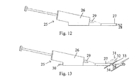
- the term "introducer” is therefore herein meant to encompass both separate introducers and introducers which are part of another device. In Fig. 12 such a tool 25 for closing a puncture wound is illustrated.
- the tool 25 comprises basically a housing 26 and a distal introducer 27, which is fixedly connected to the housing 26.
- the introducer 27 is provided with a first hole 28, which through a canal (not shown in the figure) is in fluid communication with an opening 29 provided in the housing 26.
- This canal can be provided as a longitudinal recess in the surface of a guide rod over which the introducer 27 is threaded, or the canal can be provided as a longitudinal, internal hole within the guide rod.
- the introducer 27 of the tool 25 has, over a guide rod 16, been inserted from the skin 31 of a patient, through tissue 32 and through the wall 33 of a blood vessel 34.
- the introducer 27 is positioned by means of the same positioning operation as was illustrated in Fig. 7 to Fig. 9, and the introducer 27 of Fig. 13 is therefore in the same position as the introducer 17 of Fig. 9, with the difference that the introducer 27 is a part of a tool 25 for closing a puncture wound rather than being a separate introducer.
- blood can flow into the hole 28 in the introducer 27 through a canal provided in the guide rod 16 and out from the opening 29 provided in the housing 26, thereby providing a user with a verification that the introducer 27 is at the correct position with the vessel 34.
- the method and the guide rod according to the present invention are not limited to be used in blood vessels, but could be used in any vessel when a first introducer has to be replaced with a second introducer.
- the guide rod could be provided with a measurement scale, for example, in the form of centimeter or millimeter marks, that provide a user with an indication of how far the guide rod is inserted into the introducer.
Abstract
Description
Claims (11)
- A guide for insertion of a new introducer in replacement of a first introducer such that a distal end of said new introducer reaches through a puncture hole in a vessel wall to be positioned inside the vessel, while a proximal end of the new introducer being located outside the skin of a patient, the guide comprisinga rod (16) having a length between a proximal end (24) and a distal end (22), and a sectional dimension transversely to said length;the transverse section being dimensioned to receive the new introducer in close relation about the circumference of the rod, and the length being dimensioned to guide the new introducer in sliding movement from the proximal end towards the distal end of the rod, anda distal portion of the rod being dimensioned for supporting the vessel wall around the puncture hole when the distal end of the rod remains inside the vessel for insertion of the new introducer.
- The guide rod (16) according to claim 1, wherein the distal portion of the rod is flexible.
- The guide rod (16) according to claim 1 or 2, wherein the proximal portion of the rod is not flexible.
- The guide rod (16) according to any previous claim, wherein the distal portion has a blunt end.
- The guide rod (16) according to any previous claim, wherein the proximal portion has a tapered end.
- The guide rod (16) according to any previous claim, wherein the distal portion can be pre-bent in such a way that it resumes its bent shape after having passed through the first introducer.
- The guide rod (16) according to any previous claim, wherein a diameter of the guide rod is equal, or almost equal, to an inner diameter of the introducer.
- The guide rod (16) according to any previous claim, wherein the diameter of the guide rod is equal, or almost equal, to a diameter of the puncture hole through the wall of the vessel.
- The guide rod (16) according to any previous claim, further comprising a measurement scale.
- The guide rod (16) according to any previous claim, wherein the surface of the guide rod is provided with a longitudinal recess.
- The guide rod (16) according to any previous claim, wherein the guide rod is provided with a longitudinal, internal hole.
Priority Applications (4)
| Application Number | Priority Date | Filing Date | Title |
|---|---|---|---|
| ES04005675T ES2301892T3 (en) | 2004-03-10 | 2004-03-10 | SYSTEM THAT INCLUDES A GUIDE BAR AND FIRST AND SECOND INTRODUCER. |
| AT04005675T ATE392855T1 (en) | 2004-03-10 | 2004-03-10 | SYSTEM COMPRISING A GUIDE WIRE AND FIRST AND SECOND INTRODUCTION DEVICES |
| EP04005675A EP1574168B1 (en) | 2004-03-10 | 2004-03-10 | System comprising a guide rod and first and second introducers |
| DE602004013274T DE602004013274T2 (en) | 2004-03-10 | 2004-03-10 | System with a guidewire and first and second introducers |
Applications Claiming Priority (1)
| Application Number | Priority Date | Filing Date | Title |
|---|---|---|---|
| EP04005675A EP1574168B1 (en) | 2004-03-10 | 2004-03-10 | System comprising a guide rod and first and second introducers |
Publications (2)
| Publication Number | Publication Date |
|---|---|
| EP1574168A1 true EP1574168A1 (en) | 2005-09-14 |
| EP1574168B1 EP1574168B1 (en) | 2008-04-23 |
Family
ID=34814282
Family Applications (1)
| Application Number | Title | Priority Date | Filing Date |
|---|---|---|---|
| EP04005675A Expired - Lifetime EP1574168B1 (en) | 2004-03-10 | 2004-03-10 | System comprising a guide rod and first and second introducers |
Country Status (4)
| Country | Link |
|---|---|
| EP (1) | EP1574168B1 (en) |
| AT (1) | ATE392855T1 (en) |
| DE (1) | DE602004013274T2 (en) |
| ES (1) | ES2301892T3 (en) |
Citations (6)
| Publication number | Priority date | Publication date | Assignee | Title |
|---|---|---|---|---|
| EP0331932A2 (en) * | 1988-03-09 | 1989-09-13 | B. Braun Melsungen AG | Catheter set for plexus anaesthesia |
| EP0397173A1 (en) * | 1989-05-11 | 1990-11-14 | Advanced Cardiovascular Systems, Inc. | Pressure monitoring guidewire with a flexible distal portion |
| DE4319033C1 (en) * | 1993-06-08 | 1994-06-30 | Braun Melsungen Ag | Seldinger device with vein catheterisation |
| US5478326A (en) * | 1992-12-10 | 1995-12-26 | Shiu; Man F. | Arterial device for control of bleeding from a puncture in an artery wall |
| US5695111A (en) * | 1992-12-22 | 1997-12-09 | Advanced Cardiovascular Systems, Inc. | Method of soldering TI containing alloys |
| US20030195560A1 (en) * | 2000-12-14 | 2003-10-16 | Core Medical, Inc. | Apparatus and methods for sealing vascular puncturess |
-
2004
- 2004-03-10 EP EP04005675A patent/EP1574168B1/en not_active Expired - Lifetime
- 2004-03-10 ES ES04005675T patent/ES2301892T3/en not_active Expired - Lifetime
- 2004-03-10 AT AT04005675T patent/ATE392855T1/en not_active IP Right Cessation
- 2004-03-10 DE DE602004013274T patent/DE602004013274T2/en not_active Expired - Lifetime
Patent Citations (6)
| Publication number | Priority date | Publication date | Assignee | Title |
|---|---|---|---|---|
| EP0331932A2 (en) * | 1988-03-09 | 1989-09-13 | B. Braun Melsungen AG | Catheter set for plexus anaesthesia |
| EP0397173A1 (en) * | 1989-05-11 | 1990-11-14 | Advanced Cardiovascular Systems, Inc. | Pressure monitoring guidewire with a flexible distal portion |
| US5478326A (en) * | 1992-12-10 | 1995-12-26 | Shiu; Man F. | Arterial device for control of bleeding from a puncture in an artery wall |
| US5695111A (en) * | 1992-12-22 | 1997-12-09 | Advanced Cardiovascular Systems, Inc. | Method of soldering TI containing alloys |
| DE4319033C1 (en) * | 1993-06-08 | 1994-06-30 | Braun Melsungen Ag | Seldinger device with vein catheterisation |
| US20030195560A1 (en) * | 2000-12-14 | 2003-10-16 | Core Medical, Inc. | Apparatus and methods for sealing vascular puncturess |
Also Published As
| Publication number | Publication date |
|---|---|
| ES2301892T3 (en) | 2008-07-01 |
| DE602004013274T2 (en) | 2009-07-16 |
| DE602004013274D1 (en) | 2008-06-05 |
| EP1574168B1 (en) | 2008-04-23 |
| ATE392855T1 (en) | 2008-05-15 |
Similar Documents
| Publication | Publication Date | Title |
|---|---|---|
| US8734366B2 (en) | Guide rod for introducer replacement | |
| US11654266B2 (en) | Devices for transvascular retrograde access placement | |
| US20230381480A1 (en) | Sheath for sealed access to a vessel | |
| JP4080960B2 (en) | Sealing device | |
| US20130144331A1 (en) | Introducer sheath | |
| US5690674A (en) | Wound closure with plug | |
| JP6062643B2 (en) | Micro access kit with taper needle | |
| US5117836A (en) | Method for measuring intracranial fluid characteristics | |
| US6110184A (en) | Introducer with vascular sealing mechanism | |
| EP0540783B1 (en) | Catheter | |
| US4650472A (en) | Apparatus and method for effecting percutaneous catheterization of a blood vessel using a small gauge introducer needle | |
| CN108348737A (en) | Shell-less guiding catheter component | |
| US4969875A (en) | Drainage device for medical use | |
| US5478326A (en) | Arterial device for control of bleeding from a puncture in an artery wall | |
| US20050049634A1 (en) | Medical closure device | |
| EP1019119B1 (en) | Intravascular catheter system with convertible sheath extension for magnetic resonance imaging and method | |
| WO2003002181A2 (en) | Catheter introducer having an expandable tip | |
| JPH08252320A (en) | Catheter rocking device | |
| JP2013013592A (en) | Dilator device for ventricular puncture | |
| JPH0749058B2 (en) | Anesthesia equipment | |
| US8585680B2 (en) | Endovascular device tip assembly incorporating a marker device and method for making the same | |
| AU2004200104B2 (en) | Guide rod for an introducer | |
| EP1574168B1 (en) | System comprising a guide rod and first and second introducers | |
| JPH10295699A (en) | Hemostasis implement | |
| CN219306864U (en) | Positioning sheath |
Legal Events
| Date | Code | Title | Description |
|---|---|---|---|
| PUAI | Public reference made under article 153(3) epc to a published international application that has entered the european phase |
Free format text: ORIGINAL CODE: 0009012 |
|
| 17P | Request for examination filed |
Effective date: 20040331 |
|
| AK | Designated contracting states |
Kind code of ref document: A1 Designated state(s): AT BE BG CH CY CZ DE DK EE ES FI FR GB GR HU IE IT LI LU MC NL PL PT RO SE SI SK TR |
|
| AX | Request for extension of the european patent |
Extension state: AL LT LV MK |
|
| AKX | Designation fees paid |
Designated state(s): AT BE BG CH CY CZ DE DK EE ES FI FR GB GR HU IE IT LI LU MC NL PL PT RO SE SI SK TR |
|
| 17Q | First examination report despatched |
Effective date: 20060918 |
|
| GRAP | Despatch of communication of intention to grant a patent |
Free format text: ORIGINAL CODE: EPIDOSNIGR1 |
|
| RTI1 | Title (correction) |
Free format text: SYSTEM COMPRISING A GUIDE ROD AND FIRST AND SECOND INTRODUCERS |
|
| GRAS | Grant fee paid |
Free format text: ORIGINAL CODE: EPIDOSNIGR3 |
|
| GRAA | (expected) grant |
Free format text: ORIGINAL CODE: 0009210 |
|
| AK | Designated contracting states |
Kind code of ref document: B1 Designated state(s): AT BE BG CH CY CZ DE DK EE ES FI FR GB GR HU IE IT LI LU MC NL PL PT RO SE SI SK TR |
|
| REG | Reference to a national code |
Ref country code: GB Ref legal event code: FG4D |
|
| REG | Reference to a national code |
Ref country code: CH Ref legal event code: EP |
|
| REF | Corresponds to: |
Ref document number: 602004013274 Country of ref document: DE Date of ref document: 20080605 Kind code of ref document: P |
|
| REG | Reference to a national code |
Ref country code: IE Ref legal event code: FG4D Free format text: LANGUAGE OF EP DOCUMENT: FRENCH |
|
| REG | Reference to a national code |
Ref country code: CH Ref legal event code: NV Representative=s name: BOVARD AG PATENTANWAELTE |
|
| REG | Reference to a national code |
Ref country code: ES Ref legal event code: FG2A Ref document number: 2301892 Country of ref document: ES Kind code of ref document: T3 |
|
| PG25 | Lapsed in a contracting state [announced via postgrant information from national office to epo] |
Ref country code: SI Free format text: LAPSE BECAUSE OF FAILURE TO SUBMIT A TRANSLATION OF THE DESCRIPTION OR TO PAY THE FEE WITHIN THE PRESCRIBED TIME-LIMIT Effective date: 20080423 |
|
| PG25 | Lapsed in a contracting state [announced via postgrant information from national office to epo] |
Ref country code: PT Free format text: LAPSE BECAUSE OF FAILURE TO SUBMIT A TRANSLATION OF THE DESCRIPTION OR TO PAY THE FEE WITHIN THE PRESCRIBED TIME-LIMIT Effective date: 20080923 Ref country code: FI Free format text: LAPSE BECAUSE OF FAILURE TO SUBMIT A TRANSLATION OF THE DESCRIPTION OR TO PAY THE FEE WITHIN THE PRESCRIBED TIME-LIMIT Effective date: 20080423 Ref country code: BG Free format text: LAPSE BECAUSE OF FAILURE TO SUBMIT A TRANSLATION OF THE DESCRIPTION OR TO PAY THE FEE WITHIN THE PRESCRIBED TIME-LIMIT Effective date: 20080723 |
|
| PG25 | Lapsed in a contracting state [announced via postgrant information from national office to epo] |
Ref country code: AT Free format text: LAPSE BECAUSE OF FAILURE TO SUBMIT A TRANSLATION OF THE DESCRIPTION OR TO PAY THE FEE WITHIN THE PRESCRIBED TIME-LIMIT Effective date: 20080423 Ref country code: PL Free format text: LAPSE BECAUSE OF FAILURE TO SUBMIT A TRANSLATION OF THE DESCRIPTION OR TO PAY THE FEE WITHIN THE PRESCRIBED TIME-LIMIT Effective date: 20080423 |
|
| ET | Fr: translation filed | ||
| PG25 | Lapsed in a contracting state [announced via postgrant information from national office to epo] |
Ref country code: CZ Free format text: LAPSE BECAUSE OF FAILURE TO SUBMIT A TRANSLATION OF THE DESCRIPTION OR TO PAY THE FEE WITHIN THE PRESCRIBED TIME-LIMIT Effective date: 20080423 Ref country code: SE Free format text: LAPSE BECAUSE OF FAILURE TO SUBMIT A TRANSLATION OF THE DESCRIPTION OR TO PAY THE FEE WITHIN THE PRESCRIBED TIME-LIMIT Effective date: 20080723 Ref country code: DK Free format text: LAPSE BECAUSE OF FAILURE TO SUBMIT A TRANSLATION OF THE DESCRIPTION OR TO PAY THE FEE WITHIN THE PRESCRIBED TIME-LIMIT Effective date: 20080423 |
|
| PG25 | Lapsed in a contracting state [announced via postgrant information from national office to epo] |
Ref country code: SK Free format text: LAPSE BECAUSE OF FAILURE TO SUBMIT A TRANSLATION OF THE DESCRIPTION OR TO PAY THE FEE WITHIN THE PRESCRIBED TIME-LIMIT Effective date: 20080423 Ref country code: RO Free format text: LAPSE BECAUSE OF FAILURE TO SUBMIT A TRANSLATION OF THE DESCRIPTION OR TO PAY THE FEE WITHIN THE PRESCRIBED TIME-LIMIT Effective date: 20080423 |
|
| PLBE | No opposition filed within time limit |
Free format text: ORIGINAL CODE: 0009261 |
|
| STAA | Information on the status of an ep patent application or granted ep patent |
Free format text: STATUS: NO OPPOSITION FILED WITHIN TIME LIMIT |
|
| 26N | No opposition filed |
Effective date: 20090126 |
|
| PG25 | Lapsed in a contracting state [announced via postgrant information from national office to epo] |
Ref country code: EE Free format text: LAPSE BECAUSE OF FAILURE TO SUBMIT A TRANSLATION OF THE DESCRIPTION OR TO PAY THE FEE WITHIN THE PRESCRIBED TIME-LIMIT Effective date: 20080423 |
|
| PG25 | Lapsed in a contracting state [announced via postgrant information from national office to epo] |
Ref country code: IT Free format text: LAPSE BECAUSE OF FAILURE TO SUBMIT A TRANSLATION OF THE DESCRIPTION OR TO PAY THE FEE WITHIN THE PRESCRIBED TIME-LIMIT Effective date: 20080423 |
|
| PG25 | Lapsed in a contracting state [announced via postgrant information from national office to epo] |
Ref country code: MC Free format text: LAPSE BECAUSE OF NON-PAYMENT OF DUE FEES Effective date: 20090331 |
|
| PG25 | Lapsed in a contracting state [announced via postgrant information from national office to epo] |
Ref country code: IE Free format text: LAPSE BECAUSE OF NON-PAYMENT OF DUE FEES Effective date: 20090310 |
|
| PG25 | Lapsed in a contracting state [announced via postgrant information from national office to epo] |
Ref country code: GR Free format text: LAPSE BECAUSE OF FAILURE TO SUBMIT A TRANSLATION OF THE DESCRIPTION OR TO PAY THE FEE WITHIN THE PRESCRIBED TIME-LIMIT Effective date: 20080724 |
|
| REG | Reference to a national code |
Ref country code: CH Ref legal event code: PFA Owner name: RADI MEDICAL SYSTEMS AB Free format text: RADI MEDICAL SYSTEMS AB#PALMBLADSGATAN 10#754 50 UPPSALA (SE) -TRANSFER TO- RADI MEDICAL SYSTEMS AB#PALMBLADSGATAN 10#754 50 UPPSALA (SE) |
|
| PG25 | Lapsed in a contracting state [announced via postgrant information from national office to epo] |
Ref country code: HU Free format text: LAPSE BECAUSE OF FAILURE TO SUBMIT A TRANSLATION OF THE DESCRIPTION OR TO PAY THE FEE WITHIN THE PRESCRIBED TIME-LIMIT Effective date: 20081024 |
|
| PG25 | Lapsed in a contracting state [announced via postgrant information from national office to epo] |
Ref country code: TR Free format text: LAPSE BECAUSE OF FAILURE TO SUBMIT A TRANSLATION OF THE DESCRIPTION OR TO PAY THE FEE WITHIN THE PRESCRIBED TIME-LIMIT Effective date: 20080423 |
|
| PG25 | Lapsed in a contracting state [announced via postgrant information from national office to epo] |
Ref country code: CY Free format text: LAPSE BECAUSE OF FAILURE TO SUBMIT A TRANSLATION OF THE DESCRIPTION OR TO PAY THE FEE WITHIN THE PRESCRIBED TIME-LIMIT Effective date: 20080423 |
|
| PGFP | Annual fee paid to national office [announced via postgrant information from national office to epo] |
Ref country code: CH Payment date: 20130325 Year of fee payment: 10 |
|
| PGFP | Annual fee paid to national office [announced via postgrant information from national office to epo] |
Ref country code: LU Payment date: 20130408 Year of fee payment: 10 |
|
| PGFP | Annual fee paid to national office [announced via postgrant information from national office to epo] |
Ref country code: BE Payment date: 20130327 Year of fee payment: 10 |
|
| PGFP | Annual fee paid to national office [announced via postgrant information from national office to epo] |
Ref country code: NL Payment date: 20130326 Year of fee payment: 10 |
|
| REG | Reference to a national code |
Ref country code: NL Ref legal event code: V1 Effective date: 20141001 |
|
| PG25 | Lapsed in a contracting state [announced via postgrant information from national office to epo] |
Ref country code: LU Free format text: LAPSE BECAUSE OF NON-PAYMENT OF DUE FEES Effective date: 20140310 |
|
| REG | Reference to a national code |
Ref country code: CH Ref legal event code: PL |
|
| PG25 | Lapsed in a contracting state [announced via postgrant information from national office to epo] |
Ref country code: LI Free format text: LAPSE BECAUSE OF NON-PAYMENT OF DUE FEES Effective date: 20140331 Ref country code: CH Free format text: LAPSE BECAUSE OF NON-PAYMENT OF DUE FEES Effective date: 20140331 |
|
| PG25 | Lapsed in a contracting state [announced via postgrant information from national office to epo] |
Ref country code: NL Free format text: LAPSE BECAUSE OF NON-PAYMENT OF DUE FEES Effective date: 20141001 |
|
| REG | Reference to a national code |
Ref country code: FR Ref legal event code: PLFP Year of fee payment: 12 |
|
| REG | Reference to a national code |
Ref country code: DE Ref legal event code: R082 Ref document number: 602004013274 Country of ref document: DE Representative=s name: HOFFMANN - EITLE PATENT- UND RECHTSANWAELTE PA, DE Ref country code: DE Ref legal event code: R081 Ref document number: 602004013274 Country of ref document: DE Owner name: ST. JUDE MEDICAL COORDINATION CENTER BVBA, BE Free format text: FORMER OWNER: RADI MEDICAL SYSTEMS AB, UPPSALA, SE |
|
| REG | Reference to a national code |
Ref country code: GB Ref legal event code: 732E Free format text: REGISTERED BETWEEN 20150827 AND 20150902 |
|
| REG | Reference to a national code |
Ref country code: ES Ref legal event code: PC2A Owner name: ST. JUDE MEDICAL COORDINATION CENTER BVBA Effective date: 20150923 |
|
| REG | Reference to a national code |
Ref country code: FR Ref legal event code: TP Owner name: ST. JUDE MEDICAL COORDINATION CENTER BVBA, BE Effective date: 20160113 |
|
| REG | Reference to a national code |
Ref country code: FR Ref legal event code: PLFP Year of fee payment: 13 |
|
| REG | Reference to a national code |
Ref country code: FR Ref legal event code: PLFP Year of fee payment: 14 |
|
| PG25 | Lapsed in a contracting state [announced via postgrant information from national office to epo] |
Ref country code: BE Free format text: LAPSE BECAUSE OF NON-PAYMENT OF DUE FEES Effective date: 20140331 |
|
| REG | Reference to a national code |
Ref country code: FR Ref legal event code: PLFP Year of fee payment: 15 |
|
| PGFP | Annual fee paid to national office [announced via postgrant information from national office to epo] |
Ref country code: GB Payment date: 20180327 Year of fee payment: 15 |
|
| PGFP | Annual fee paid to national office [announced via postgrant information from national office to epo] |
Ref country code: FR Payment date: 20180326 Year of fee payment: 15 |
|
| PGFP | Annual fee paid to national office [announced via postgrant information from national office to epo] |
Ref country code: DE Payment date: 20180328 Year of fee payment: 15 Ref country code: ES Payment date: 20180402 Year of fee payment: 15 |
|
| REG | Reference to a national code |
Ref country code: DE Ref legal event code: R119 Ref document number: 602004013274 Country of ref document: DE |
|
| GBPC | Gb: european patent ceased through non-payment of renewal fee |
Effective date: 20190310 |
|
| PG25 | Lapsed in a contracting state [announced via postgrant information from national office to epo] |
Ref country code: DE Free format text: LAPSE BECAUSE OF NON-PAYMENT OF DUE FEES Effective date: 20191001 Ref country code: GB Free format text: LAPSE BECAUSE OF NON-PAYMENT OF DUE FEES Effective date: 20190310 |
|
| PG25 | Lapsed in a contracting state [announced via postgrant information from national office to epo] |
Ref country code: FR Free format text: LAPSE BECAUSE OF NON-PAYMENT OF DUE FEES Effective date: 20190331 |
|
| REG | Reference to a national code |
Ref country code: ES Ref legal event code: FD2A Effective date: 20200727 |
|
| PG25 | Lapsed in a contracting state [announced via postgrant information from national office to epo] |
Ref country code: ES Free format text: LAPSE BECAUSE OF NON-PAYMENT OF DUE FEES Effective date: 20190311 |