EP1574179B1 - Ultrasonic dental tool - Google Patents
Ultrasonic dental tool Download PDFInfo
- Publication number
- EP1574179B1 EP1574179B1 EP05012327.2A EP05012327A EP1574179B1 EP 1574179 B1 EP1574179 B1 EP 1574179B1 EP 05012327 A EP05012327 A EP 05012327A EP 1574179 B1 EP1574179 B1 EP 1574179B1
- Authority
- EP
- European Patent Office
- Prior art keywords
- tool
- distal end
- proximal end
- tip
- angle
- Prior art date
- Legal status (The legal status is an assumption and is not a legal conclusion. Google has not performed a legal analysis and makes no representation as to the accuracy of the status listed.)
- Expired - Lifetime
Links
Images

Classifications
-
- A—HUMAN NECESSITIES
- A61—MEDICAL OR VETERINARY SCIENCE; HYGIENE
- A61C—DENTISTRY; APPARATUS OR METHODS FOR ORAL OR DENTAL HYGIENE
- A61C3/00—Dental tools or instruments
- A61C3/16—Dentists' forceps or clamps for removing crowns
- A61C3/166—Dentists' forceps or clamps for removing crowns acting by vibration
-
- A—HUMAN NECESSITIES
- A61—MEDICAL OR VETERINARY SCIENCE; HYGIENE
- A61C—DENTISTRY; APPARATUS OR METHODS FOR ORAL OR DENTAL HYGIENE
- A61C17/00—Devices for cleaning, polishing, rinsing or drying teeth, teeth cavities or prostheses; Saliva removers; Dental appliances for receiving spittle
- A61C17/16—Power-driven cleaning or polishing devices
- A61C17/20—Power-driven cleaning or polishing devices using ultrasonics
-
- A—HUMAN NECESSITIES
- A61—MEDICAL OR VETERINARY SCIENCE; HYGIENE
- A61C—DENTISTRY; APPARATUS OR METHODS FOR ORAL OR DENTAL HYGIENE
- A61C5/00—Filling or capping teeth
- A61C5/40—Implements for surgical treatment of the roots or nerves of the teeth; Nerve needles; Methods or instruments for medication of the roots
- A61C5/42—Files for root canals; Handgrips or guiding means therefor
Definitions
- This invention relates generally to ultrasonic dental tools and more specifically to special non-surgical ultrasonic root canal tools.
- a properly shaped root canal presents a gradually tapering cone with the narrowest part directed apically.
- a typical root canal is prepared by mechanical instruments used to enlarge the root canal by physically removing internal root canal tooth structure, dentin, by rotational cutting or abrasive action. These tools are tapered and pointed metal instruments with cutting edges so that the cutting occurs either on a push or pull of the stroke. With these instruments the dentist through hand manipulation prepares the canal for precise filling. The object of the preparation is to attain an apical terminus kept as small as practical in order to achieve more effective packing with greater control upon an effectively prepared seat.
- the instruments of the Malmin patent are disclosed and designed for selective positioning of abrasive materials to eliminate cutting edges and thereby eliminate the need for tempering the instruments.
- This construction reportedly provides greater adaptabilitv to eliminate breakage of the tools.
- it fails to provide configurations enabling it to be used with ultrasonic power units in remote or posterior areas of the mouth.
- it fails to provide a construction enabling the viewing of the area of cutting in the root canal.
- a dental vibrating scoler with a contra-angle is known from US 5 100 321 .
- a primary objective of this invention is to provide an improved ultrasonic dental non-surgical tool having a tip that is shaped to provide improved procedural access.
- Another objective is to provide a tool that can be made small enough for microendodontics.
- a tool for dental preparations in accordance with the present invention, designated generally by the numeral 10.
- the tool is shown connected to an ultrasonic vibrator or transducer 12 (shown in phantom) of generally well-known conventional construction.
- the tool as illustrated, comprises an elongated shank having connecting means 14 at a proximal end.
- the connection means in shown in the form of a threaded socket for threadably mounting on the end of a shaft and having a flat 16 for engagement by a wrench or the like for threadably tightening and loosening the tool.
- the tool has a proximal end portion 18 which is curved to form what is commonly called a contra-angle.
- This contra-angle portion is curved or bent in a first direction away from the axis of the proximal end at an angle A of about 15-25°, extending away from the proximal end. This contra-angle portion then curves or bends back across the axis of the proximal end or connection means at an angle B of about 70° to the axis of the connecting means.
- the proximal portion 18 extends outward from the connecting collar 14 and is of a generally uniform diameter with the conira-angle curved in a manner, as illustrated.
- An intermediate portion or section 20 of the shaft tapers gradually down to a distal or working end portion 22, having a generally uniform cylindrical configuration extending from the intermediate portion 20 outward to a tip 24 which may have a sharpened point or other form.
- This portion 22 is the primary working portion and may have a length of from about 0.25 to about 0.394 inches or six to about ten or twelve (6-10/12) mm. This portion has a diameter of about .015 to about 0.0250 inches or about .4 to 0.6 mm.
- the typical tool will come in sets of, for example, three tools with a first having an end of about 0.25 inches or 6 mm in length and about 0.0250 inches or about 0.6 mm in diameter for working in the coronal aspect of the tooth from the crown area. This is designed for performing non-surgical root canal through a crown opening.
- a medium sub-orifice tip or tool will be provided in the range of about 5 mm in length and a diameter of about 6 mm in diameter for working in the medial aspect of the root while perfonning non-surgical root canal work at this point through the crown opening.
- a long sub-orifice tip of about 10 mm and about .4/.5 mm in diameter is provided for working in the apical aspect or area of the root while performing root canal work.
- the tool is designed to use in the preparation of tooth root canals.
- the tool is shown in use in a canal of a tooth 26 having an opening 28 in the crown of the tooth.
- the tool is inserted through the opening 28 and into a canal 30 of a root 32 of the tooth.
- the working distal end 22 of the tool is of a uniform cylindrical diameter throughout its length, such that when positioned in the tapered root canal 30. it provides space 34 around the shaft to enable the operator to view or see the wall area surrounding the tool as it's performing its work.
- This cylindrical shape doesn't wedge in the canal as does the tapered tool of the prior art. It also gives debris room (space 34) to move out of the canal.
- the size and configuration of the tool provides a strong rigid construction that reduces the possibility of breakage of the tool during use.
- the tool is also hardened and tempered or coated, as will be further explained to further strengthen it for its utility.
- the tool is shaped with a contra-angle, as discussed above, wherein it curves first to one side of the axis and then extends across at an angle to the other side of the axis where the distal point is located. This angle provides better access to posterior areas of the mouth of the patient.
- This configuration has been utilized in hand tools for dental work, but has not been utilized in the ultrasonic tools.
- the present invention provides instruments that, because of the critical characteristics, allow them to work predictably, safely, and efficiently to all teeth within the dentition.
- the double bent shaft known as a contra-angle, enables dramatic improvement in procedural access.
- This configuration is unique to endodontic non-surgical ultrasonic instruments and allows them to work in the posterior teeth, as well as the anterior teeth.
- the most distal aspect of the ultrasonic instruments have been designed with up to 10 mm of parallelism, that is uniform diameter cylindrical portion then progressively, rather than abruptly, tapers toward the proximal end of the contra-angle. This feature allows massive improvement in vision when the instrument is placed inside a canal.
- Parallel sided i.e.
- cylindrical ultrasonic instruments allow for improved vision with loupes, magnification glasses or the operating microscopes when looking deep between the walls of the canal and the introduced ultrasonic instrument. Over the length of the instrument, a smooth transition from parallel sidewalls to progressive taper enhances strength and instrument activity while economically reducing expensive tip breakage, as evidenced in clinical trials.
- the instruments may also be coated, as will be described, which provides a longer useful clinical life by reducing instrument breakage. It also produces more measurable energy, as compared to prior art and enhances performance in non-surgical endodontic treatments.
- the coating creates an abrasive which allows for tooth and efficient side and/or end cutting.
- the special coating eliminates chipping, gouging and notential dental burning, noted with tools according to the prior art.
- the contra-angled head and designed shape provides enhanced energy for the successful removal of built-ups and pulp chamber cores.
- the instrument is excellent for chasing calcified canals, uncovering hidden orifices, troughing and obstructions located within the pulp chamber or extended below the surface.
- the instruments are designed without a water port which are deemed unnecessary in this design, as well as undesirable. Flowing water creates airborne mists which can carry bacteria. In addition, flowing water obstructs the vision, which is so critical to effective utilization of the instruments.
- an alternate tool designated generally by the numeral 42, is illustrated having the same overall centra-angle configuration as that of Fig. 1 , but with a concave point or tip 50.
- the tool has a connector socket 44 with a contra-angle portion 46 and a tapered portion 48 and concave tip 50.
- This tool or instrument was conceived and designed to efficiently apply energy to the removal of crowns, bridges, posts and other materials.
- the tool with its concave tip 50 dramatically improves energy, clinical applications and efficiency when removing crowns, bridges, posts and other restorative materials.
- This concave shape in this instrument is unique as it allows more intimate contact and transference of ultrasonic energy to the obstruction, such as posts, crowns, epoxies and cements and restorative materials.
- the tool is applied to a crown 52 (shown in phantom) which is mounted on a portion of a tooth 54 by means of a post 56 cemented into a bore 58 of the tooth.
- a crown 52 shown in phantom
- the concave shape tip of this instrument provides a more intimate contact and transference of ultrasonic energy to the tooth crown or other obstruction.
- the instruments may, as mentioned above, be coated, such as disclosed in copending Application S.N. 08/546,336 filed October 20, 1995 and published as WO 9714373 and entitled "Hardening Process for Ultrasonic Dental Tips".
- One preferred coating is metal nitride.
- the metal nitride can be applied very thinly and still imparts excellent hardness properties in contrast to the relatively thick diamond coatings of the prior art that are required to gain hardness.
- the thin coating is desirable because the tips do not have to support the weight of the diamond abrasive, allowing for smaller diameter tips.
- the small size allows the tip to access hard to reach areas that were not reachable with prior art tips. The small size also allows for a less intrusive invasion of the subject, for example, a smaller filling may be added to a tooth.
- the metal coating is preferably applied over the entire tool with the exception of threads.
- the preferred overall process for creating the tips is as follows.
- An ultrasonic dental tip is manufactured, bent into the proper shape, and roughened by an externally applied abrasive process.
- a metal nitride coating is applied to the roughened outer surface.
- the metal element is selected from the group consisting of Zirconium (Zr) and Titanium (Ti). Between a Ti-N and Zr-N coating, the latter is the hardest at about 3000 Vickers while the former is about 2800 Vickers. Either is harder than carbide instruments which are commonly used in the prior art, but softer than an instrument prepared with expensive diamond abrasives. However, either metal nitride provides a very hard surface tip with far less cost than those using diamonds.
- the tip is comprised of a metal substrate, such as stainless steel, and in particular the inventors have recognized that ASTM 13-8 stainless steel is a good choice for the substrate. It has been further recognized by the inventors that it is beneficial to heat treat the steel after the roughing step to achieve a Rockwell-C hardness rating of about 40-42. Heat treating is a well known process that involves heating and cooling of a metal in the solid state for the purpose of obtaining certain desirable properties including increased hardness.
- the coating may be applied by any well-known technique in the art. While not desiring to be limited to any particular method of coating, the inventors have discovered that the well-known technique of using physical vapor deposition equipment employing cathodic arc techniques is a satisfactory way to deposit thin films of the metal nitrides on dental surgical tips.
- the coating is preferably applied very thinly so that its average thickness is about 0,0005 centimers or 0.0002 inches.
- An advantage of such a thin coating is that very small diameter tips can be created that are extremely hard and yet abrasive. Such small diameter tips are desirable in microendodontic procedures.
Description
- This invention relates generally to ultrasonic dental tools and more specifically to special non-surgical ultrasonic root canal tools.
- Dental surgeons commonly use a tool usually called a tip coupled to an ultrasonic generator for operations on teeth. bones, and soft tissue including dislodging and removal of dental material. The use of ultrasonic generators for powering tools for clinical dentistry has been widely used in virtually all areas, except for root canal. Root canal work until recently has been largely limited to manual instruments for various reasons. One of the main reasons is the difficulty of providing tools that can be powered by ultrasonic generators that also provide access of the tool for precision root canal work. For this reason, such tools in the past have been largely limited to manually manipulated tools and instruments, such as disclosed for example, in
U.S. patent 5,026.254 issued June 25, 1991 to Martin. As expressed in the background of that patent, the success of root a canal depends upon very precise and controlled preparation and shaping of the root canal. - A properly shaped root canal presents a gradually tapering cone with the narrowest part directed apically. A typical root canal is prepared by mechanical instruments used to enlarge the root canal by physically removing internal root canal tooth structure, dentin, by rotational cutting or abrasive action. These tools are tapered and pointed metal instruments with cutting edges so that the cutting occurs either on a push or pull of the stroke. With these instruments the dentist through hand manipulation prepares the canal for precise filling. The object of the preparation is to attain an apical terminus kept as small as practical in order to achieve more effective packing with greater control upon an effectively prepared seat.
- Recent years have seen the proposed use of ultrasonically powered instruments for the preparation of root canals. Examples of instruments of this type are disclosed in
U.S. patent 4.019,254, issued April 26. 1977 to Malmin ,U.S. 5,094,617 issued March 10, 1992 to Carr andPCT Publication WO 86/05967 - The instruments of the Malmin patent are disclosed and designed for selective positioning of abrasive materials to eliminate cutting edges and thereby eliminate the need for tempering the instruments. This construction reportedly provides greater adaptabilitv to eliminate breakage of the tools. However, it fails to provide configurations enabling it to be used with ultrasonic power units in remote or posterior areas of the mouth. In addition, it fails to provide a construction enabling the viewing of the area of cutting in the root canal.
- A dental vibrating scoler with a contra-angle is known from
US 5 100 321 . - Therefore, there is a need for an improved ultrasonic dental tool for enabling the effective root canal preparation from the crown area of the tooth.
- A primary objective of this invention is to provide an improved ultrasonic dental non-surgical tool having a tip that is shaped to provide improved procedural access.
- Another objective is to provide a tool that can be made small enough for microendodontics.
- In accordance with a primary aspect of the present invention a dental tool, as defined in
claims 1, 9 and 11, for use with an ultrasonic transducer comprises a substantially elongate tool defined by a shaft having a proximal end with means for attachment to an ultrasonic transducer, and a distal end having a tip configured for performing a dental procedure, an intermediate contra-angle portion, and a portion of straight cylindrical configuration from said tip inward toward said proximal end. - Preferred embodiments are defined in the dependent claims.
- The objects, advantages and features of this invention will be more readily appreciated from the following detailed description, when read in conjunction with the accompanying drawing, in which:
-
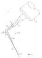
Fig. 1 is a side elevation view of an ultrasonic dental tool constructed in accordance with a preferred embodiment of the invention; -
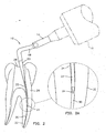
Fig. 2 is a view likeFig. 1 showing the tool in a root canal in a tooth; -
Fig. 2a is an enlarged detailed view of the tip of the tool as shown inFig. 2 ; -
Fig. 3 is an side elevation view of another example of an ultrasonic dental tool shown in use and which does not form part of the invention; and -
Fig. 4 is an enlarged detailed view of the tool ofFig. 3 . - The present invention is described with reference to a preferred embodiment of the invention as illustrated in the drawings. While this invention is described in terms of the best mode for achieving this invention's objectives, it will be appreciated by those skilled in the art that variations may be made in view of these teachings without deviating from the scope of the invention as defined by the appended claims.
- Referring to
Fig. 1 of the drawings there is illustrated an exemplary embodiment of a tool for dental preparations, in accordance with the present invention, designated generally by thenumeral 10. The tool is shown connected to an ultrasonic vibrator or transducer 12 (shown in phantom) of generally well-known conventional construction. The tool, as illustrated, comprises an elongated shank having connecting means 14 at a proximal end. The connection means in shown in the form of a threaded socket for threadably mounting on the end of a shaft and having a flat 16 for engagement by a wrench or the like for threadably tightening and loosening the tool. The tool has aproximal end portion 18 which is curved to form what is commonly called a contra-angle. This contra-angle portion is curved or bent in a first direction away from the axis of the proximal end at an angle A of about 15-25°, extending away from the proximal end. This contra-angle portion then curves or bends back across the axis of the proximal end or connection means at an angle B of about 70° to the axis of the connecting means. - The
proximal portion 18 extends outward from the connectingcollar 14 and is of a generally uniform diameter with the conira-angle curved in a manner, as illustrated. An intermediate portion orsection 20 of the shaft tapers gradually down to a distal or workingend portion 22, having a generally uniform cylindrical configuration extending from theintermediate portion 20 outward to atip 24 which may have a sharpened point or other form. Thisportion 22 is the primary working portion and may have a length of from about 0.25 to about 0.394 inches or six to about ten or twelve (6-10/12) mm. This portion has a diameter of about .015 to about 0.0250 inches or about .4 to 0.6 mm. - The typical tool will come in sets of, for example, three tools with a first having an end of about 0.25 inches or 6 mm in length and about 0.0250 inches or about 0.6 mm in diameter for working in the coronal aspect of the tooth from the crown area. This is designed for performing non-surgical root canal through a crown opening. A medium sub-orifice tip or tool will be provided in the range of about 5 mm in length and a diameter of about 6 mm in diameter for working in the medial aspect of the root while perfonning non-surgical root canal work at this point through the crown opening. Finally, a long sub-orifice tip of about 10 mm and about .4/.5 mm in diameter is provided for working in the apical aspect or area of the root while performing root canal work.
- Referring to
Figs. 2 and 2A , the tool is designed to use in the preparation of tooth root canals. As illustrated, the tool is shown in use in a canal of atooth 26 having anopening 28 in the crown of the tooth. The tool is inserted through theopening 28 and into acanal 30 of aroot 32 of the tooth. As can be seen inFig. 2A , the workingdistal end 22 of the tool is of a uniform cylindrical diameter throughout its length, such that when positioned in thetapered root canal 30. it providesspace 34 around the shaft to enable the operator to view or see the wall area surrounding the tool as it's performing its work. This cylindrical shape doesn't wedge in the canal as does the tapered tool of the prior art. It also gives debris room (space 34) to move out of the canal. - The size and configuration of the tool, with its gradual divergence at 20 from minimum diameter at the
distal end portion 22 to maximum diameter at theproximal end portion 18, provides a strong rigid construction that reduces the possibility of breakage of the tool during use. The tool is also hardened and tempered or coated, as will be further explained to further strengthen it for its utility. - The tool is shaped with a contra-angle, as discussed above, wherein it curves first to one side of the axis and then extends across at an angle to the other side of the axis where the distal point is located. This angle provides better access to posterior areas of the mouth of the patient. This configuration has been utilized in hand tools for dental work, but has not been utilized in the ultrasonic tools.
- The present invention provides instruments that, because of the critical characteristics, allow them to work predictably, safely, and efficiently to all teeth within the dentition. The double bent shaft, known as a contra-angle, enables dramatic improvement in procedural access. This configuration is unique to endodontic non-surgical ultrasonic instruments and allows them to work in the posterior teeth, as well as the anterior teeth. The most distal aspect of the ultrasonic instruments have been designed with up to 10 mm of parallelism, that is uniform diameter cylindrical portion then progressively, rather than abruptly, tapers toward the proximal end of the contra-angle. This feature allows massive improvement in vision when the instrument is placed inside a canal. Parallel sided (i.e. cylindrical) ultrasonic instruments allow for improved vision with loupes, magnification glasses or the operating microscopes when looking deep between the walls of the canal and the introduced ultrasonic instrument. Over the length of the instrument, a smooth transition from parallel sidewalls to progressive taper enhances strength and instrument activity while economically reducing expensive tip breakage, as evidenced in clinical trials.
- The instruments may also be coated, as will be described, which provides a longer useful clinical life by reducing instrument breakage. It also produces more measurable energy, as compared to prior art and enhances performance in non-surgical endodontic treatments. The coating creates an abrasive which allows for tooth and efficient side and/or end cutting. The special coating eliminates chipping, gouging and notential dental burning, noted with tools according to the prior art.
- The contra-angled head and designed shape provides enhanced energy for the successful removal of built-ups and pulp chamber cores. In addition, the instrument is excellent for chasing calcified canals, uncovering hidden orifices, troughing and obstructions located within the pulp chamber or extended below the surface.
- These uniquely configured instruments afford significant visual advantages, as their design and progressively smaller profiles allow them to work in the coronal, middle, and apical 1/3's of virtually all roots of all teeth. Its unsurpassed energy makes them ideal for eliminating broken instruments, chasing calcified canals and negotiating iatrogenic blocks.
- The instruments are designed without a water port which are deemed unnecessary in this design, as well as undesirable. Flowing water creates airborne mists which can carry bacteria. In addition, flowing water obstructs the vision, which is so critical to effective utilization of the instruments.
- Referring to
Figs. 3 and 4 , an alternate tool, designated generally by the numeral 42, is illustrated having the same overall centra-angle configuration as that ofFig. 1 , but with a concave point ortip 50. The tool has aconnector socket 44 with a contra-angle portion 46 and a taperedportion 48 andconcave tip 50. This tool or instrument was conceived and designed to efficiently apply energy to the removal of crowns, bridges, posts and other materials. The tool with itsconcave tip 50 dramatically improves energy, clinical applications and efficiency when removing crowns, bridges, posts and other restorative materials. This concave shape in this instrument is unique as it allows more intimate contact and transference of ultrasonic energy to the obstruction, such as posts, crowns, epoxies and cements and restorative materials. - As illustrated in
Fig 3 , the tool is applied to a crown 52 (shown in phantom) which is mounted on a portion of a tooth 54 by means of apost 56 cemented into abore 58 of the tooth. As shown in detail inFig. 4 , the concave shape tip of this instrument provides a more intimate contact and transference of ultrasonic energy to the tooth crown or other obstruction. - The instruments may, as mentioned above, be coated, such as disclosed in copending Application
S.N. 08/546,336 filed October 20, 1995 and published asWO 9714373 - In general, the preferred overall process for creating the tips is as follows. An ultrasonic dental tip is manufactured, bent into the proper shape, and roughened by an externally applied abrasive process. Then, a metal nitride coating is applied to the roughened outer surface. Preferably, the metal element is selected from the group consisting of Zirconium (Zr) and Titanium (Ti). Between a Ti-N and Zr-N coating, the latter is the hardest at about 3000 Vickers while the former is about 2800 Vickers. Either is harder than carbide instruments which are commonly used in the prior art, but softer than an instrument prepared with expensive diamond abrasives. However, either metal nitride provides a very hard surface tip with far less cost than those using diamonds. Further, one can expect long wear from tips created by the process of this invention because Ti-N and Zr-N are both highly resistant to abrasion and corrosion. Zr-N has not been used as a hard coating for surgical tips prior to this invention. This invention is based to an extent on the inventors critical recognition of its desirable properties.
- Preferably, the tip is comprised of a metal substrate, such as stainless steel, and in particular the inventors have recognized that ASTM 13-8 stainless steel is a good choice for the substrate. It has been further recognized by the inventors that it is beneficial to heat treat the steel after the roughing step to achieve a Rockwell-C hardness rating of about 40-42. Heat treating is a well known process that involves heating and cooling of a metal in the solid state for the purpose of obtaining certain desirable properties including increased hardness.
- One of the benefits of using stainless steel is that it is easy to heat treat. Empirical evidence shows that good results can be obtained by subjecting 13-8 stainless steel to a temperature of about 900° for about two hours.
- When the roughing and heat treating is followed by the application of a metal nitride coating the result is an extremely hard tip having very desirable cutting abilities. The coating may be applied by any well-known technique in the art. While not desiring to be limited to any particular method of coating, the inventors have discovered that the well-known technique of using physical vapor deposition equipment employing cathodic arc techniques is a satisfactory way to deposit thin films of the metal nitrides on dental surgical tips. The coating is preferably applied very thinly so that its average thickness is about 0,0005 centimers or 0.0002 inches. An advantage of such a thin coating is that very small diameter tips can be created that are extremely hard and yet abrasive. Such small diameter tips are desirable in microendodontic procedures.
- While we have illustrated and described our invention by means of specific embodiments, it is to be understood that numerous changes and modifications may be made therein without departing from the scope of the invention as defined in the appended claims.
Claims (13)
- A dental tool (10) for use with an ultrasonic transducer (12), the tool comprising; a substantially elongate tool defined by a shaft having a proximal end with means (14) for attachment to an ultrasonic transducer (12) and a distal end having a tip (24, 50) configured for performing a dental procedure; and
said distal end having a portion (22) of straight cylindrical wall from said tip inward toward said proximal end, and said shaft has a contra-angle (18) between said cylindrical wall (22) and said proximal end, and
said shaft tapers from said cylindrical wall to said contra-angle. - The tool of claim 1, wherein said distal end is formed with a pointed tip (24) and wherein a metal nitride coat is applied to the outer surface and has an average thickness of about 0,0005 centimeters (0,0002 inches).
- The tool of claim 1, wherein said distal end is formed with a concave tip (50) and wherein the metal member of said metal nitride is selected from the group consisting of Titanium (Ti) and Zirconium (Zr).
- The tool of claim 2, wherein said cylindrical portion (22) is about ten to about twenty millimeters in length and wherein said metal nitride is Titanium Nitride (Ti-N).
- The tool of claim 4, wherein the distal end is formed with a pointed tip and wherein the outer surface of the tool has a surface hardness of about 2800 Vickers.
- The tool of claim 2, wherein said cylindrical portion is about ten to about twenty millimeters in length and wherein said metal nitride is Zirconium nitride (Zr-N).
- The tool of claim 4, wherein the instrument is composed of stainless steel.
- The tool of claim 7, wherein the instrument is heat treated to about 40 to 42 Rockwell-C hardness prior to applying the metal nitride coating.
- An ultrasonic dental tool (10) for use in an ultrasonic transducer (12) for root canal procedures, the tool comprising:an elongated tool defined by shaft having a proximal end and a distal end, a threaded connection member (14) on said proximal end for attachment to an ultrasonic transducer, and a tip (24) configured for performing a dental procedure on said distal end, said shaft having a straight cylindrical portion (22) of uniform diameter on said distal end from said tip inward toward proximal end, a contra-angle portion (18) of substantially uniform diameter adjacent said connection member at said proximal end, and a uniform gradual tapered portion (20) intermediate said cylindrical portion at distal end and said contra-angle proximal end.
- The tool of claim 9, wherein the contra-angle portion (18) is curved outward in a first direction from said axis at an angle of about fifteen degrees and curved outward in a second direction across said axis at about forty-five degrees to said axis.
- The tool of any of claims 1, 8 or 10 wherein said distal end is formed with a pointed tip (24).
- The tool of claim 9, wherein said cylindrical portion (22) is about ten to about twenty millimeters in length.
- An ultrasonic dental tool for use in an ultrasonic transducer for root canal procedures, the tool comprising:an elongated tool (10) defined by an elongated shaft having a proximal end and a distal end, a threaded connector on said proximal end for attachment to an ultrasonic transducer, and a tip (24) configured for performing a root canal procedure on said distal end, said shaft having an elongated straight cylindrical portion (22) of uniform diameter and a length of from about 5mm to about 12mm on said distal end from said tip inward toward said proximal end, an elongated contra-angle portion (18) of substantially uniform diameter adjacent said threaded connector on said proximal end curved outward in a first direction from said axis at an angle of about fifteen degrees and curved outward in a second direction across said axis at about forty-five degrees to said axis, and a uniform gradual tapered portion (20) intermediate said cylindrical portion (18) of said distal end and said contra-angle portion (18) of said proximal end.
Applications Claiming Priority (3)
| Application Number | Priority Date | Filing Date | Title |
|---|---|---|---|
| US08/766,787 US5868570A (en) | 1996-12-13 | 1996-12-13 | Ultrasonic dental tool |
| US766787 | 1996-12-13 | ||
| EP97953238A EP0991367A1 (en) | 1996-12-13 | 1997-12-11 | Ultrasonic dental tool |
Related Parent Applications (1)
| Application Number | Title | Priority Date | Filing Date |
|---|---|---|---|
| EP97953238A Division EP0991367A1 (en) | 1996-12-13 | 1997-12-11 | Ultrasonic dental tool |
Publications (3)
| Publication Number | Publication Date |
|---|---|
| EP1574179A2 EP1574179A2 (en) | 2005-09-14 |
| EP1574179A3 EP1574179A3 (en) | 2005-11-16 |
| EP1574179B1 true EP1574179B1 (en) | 2015-09-02 |
Family
ID=25077533
Family Applications (2)
| Application Number | Title | Priority Date | Filing Date |
|---|---|---|---|
| EP97953238A Withdrawn EP0991367A1 (en) | 1996-12-13 | 1997-12-11 | Ultrasonic dental tool |
| EP05012327.2A Expired - Lifetime EP1574179B1 (en) | 1996-12-13 | 1997-12-11 | Ultrasonic dental tool |
Family Applications Before (1)
| Application Number | Title | Priority Date | Filing Date |
|---|---|---|---|
| EP97953238A Withdrawn EP0991367A1 (en) | 1996-12-13 | 1997-12-11 | Ultrasonic dental tool |
Country Status (4)
| Country | Link |
|---|---|
| US (2) | US5868570A (en) |
| EP (2) | EP0991367A1 (en) |
| JP (1) | JP4662583B2 (en) |
| WO (1) | WO1998025536A1 (en) |
Families Citing this family (55)
| Publication number | Priority date | Publication date | Assignee | Title |
|---|---|---|---|---|
| US6379155B1 (en) | 1996-06-06 | 2002-04-30 | Ultradent Products, Inc. | Endodontic systems and methods for the anatomical, sectional and progressive corono-apical preparation of root canals with instruments utilizing stops |
| US6585513B2 (en) | 1995-06-06 | 2003-07-01 | Ultradent Products, Inc. | Endodontic systems and methods for preparing apical portions of root canals with a set of files having large tapers |
| US6558163B2 (en) | 1995-06-06 | 2003-05-06 | Ultradent Products, Inc. | Endodontic systems and methods for preparing upper portions of root canals with increasingly rigid files |
| US6390819B2 (en) | 1995-06-06 | 2002-05-21 | Ultradent Products, Inc. | Endodontic systems and methods for the anatomical, sectional and progressive corono-apical preparation of root canals with dedicated stainless steel instruments and dedicated nickel/titanium instruments |
| DE19825299C1 (en) * | 1998-06-05 | 1999-11-25 | Ver Dentalwerke Antaeos | Dental root canal instrument with a top part and an instrument part, e.g. a cutter |
| WO2000074586A2 (en) | 1999-06-04 | 2000-12-14 | Dentsply International Inc. | Microendodontics ultrasonic surgical dental tool having water port and method of making same |
| US6716028B2 (en) * | 2000-08-04 | 2004-04-06 | Hu-Friedy Mfg. Co., Inc. | Ultrasonic swivel insert |
| BR0103109B1 (en) * | 2001-06-08 | 2011-09-06 | cutting tool and forming process. | |
| JP3597158B2 (en) * | 2001-09-21 | 2004-12-02 | 吉継 寺内 | Dental broken instrument removal device |
| US20030096213A1 (en) | 2001-11-20 | 2003-05-22 | Hickok Teresa R. | Universal ultrasonic finishing instrument |
| US6722882B2 (en) | 2002-02-15 | 2004-04-20 | Earth City Technologies, Inc. | Dental instruments for use with ultrasonic handpieces |
| WO2005025439A2 (en) | 2002-11-15 | 2005-03-24 | San Diego Swiss Machining, Inc. | Ultrasonic dental tip with waterguide design |
| US6948935B2 (en) * | 2002-12-30 | 2005-09-27 | The Ohio State University | Ultrasonic dental device |
| US20050136375A1 (en) * | 2003-12-20 | 2005-06-23 | Sicurelli Robert J.Jr. | Method and apparatus to remove macro and micro debris from a root canal |
| FR2869792B1 (en) * | 2004-05-05 | 2006-07-14 | Satelec Soc | ULTRASOUND DENTAL INSTRUMENT |
| JP2006271651A (en) * | 2005-03-29 | 2006-10-12 | Matsumoto Shika Univ | Needle component for liquid injection, and production method thereof |
| US8388345B2 (en) * | 2005-04-13 | 2013-03-05 | Clifford J. Ruddle | Method for cleaning a root canal system |
| US20060234182A1 (en) * | 2005-04-13 | 2006-10-19 | Ruddle Clifford J | Apparatus for cleaning a root canal system |
| US8235719B2 (en) | 2005-04-13 | 2012-08-07 | Endo Inventions, Llc | Apparatus for cleaning a root canal system |
| US8043088B2 (en) * | 2005-05-16 | 2011-10-25 | Johnson Douglas B | Endodontic procedure employing simultaneous liquefaction and acoustic debridgement |
| JP5286079B2 (en) | 2005-05-17 | 2013-09-11 | イエダ リサーチ アンド ディベロップメント カンパニー リミテッド | Low friction coating for dental and medical devices |
| US20070065773A1 (en) * | 2005-09-19 | 2007-03-22 | Hickok Teresa R | Root canal obstruction removal system |
| EP4272694A3 (en) | 2006-04-20 | 2024-01-03 | Sonendo, Inc. | Apparatus for treating root canals of teeth |
| US10835355B2 (en) | 2006-04-20 | 2020-11-17 | Sonendo, Inc. | Apparatus and methods for treating root canals of teeth |
| US7604479B2 (en) * | 2006-07-26 | 2009-10-20 | Buchanan L Stephen | Tip wrench for ultrasonic dental tool |
| US7980854B2 (en) | 2006-08-24 | 2011-07-19 | Medical Dental Advanced Technologies Group, L.L.C. | Dental and medical treatments and procedures |
| US20100330523A1 (en) * | 2007-03-30 | 2010-12-30 | Cms Dental Aps | Optical tip for photosynthesis |
| US20080248444A1 (en) * | 2007-04-04 | 2008-10-09 | Bahcall James K | Ultrasonic endodontic tip having a low-modulus of elasticity |
| WO2010080586A1 (en) * | 2008-12-18 | 2010-07-15 | Neill Hamilton Luebke | Dental and medical instruments comprising stainless steel |
| US9788925B2 (en) | 2009-08-19 | 2017-10-17 | Vicky L Moran | Transducer activated tool with water conduit |
| WO2011060327A1 (en) | 2009-11-13 | 2011-05-19 | Dentatek Corporation | Liquid jet apparatus and methods for dental treatments |
| BR112012032337A2 (en) * | 2010-06-21 | 2016-11-08 | Hadasit Med Res Service | endodontic file for root canal treatment |
| JP6241997B2 (en) | 2010-10-21 | 2017-12-06 | ソネンド インコーポレイテッド | Devices, methods and compositions for endodontic treatment |
| WO2013013148A1 (en) * | 2011-07-20 | 2013-01-24 | Balson Marc | Medical irrigation device |
| WO2013075058A1 (en) * | 2011-11-17 | 2013-05-23 | Loma Linda University | Method and devices for placing root repair materials for root-end cavities |
| EP2809246A1 (en) * | 2012-02-03 | 2014-12-10 | Satelec SAS | Cutting tips for ultrasonic surgical system |
| CN104470464A (en) | 2012-03-22 | 2015-03-25 | 索南多股份有限公司 | Apparatus and methods for cleanting teeth |
| US10631962B2 (en) | 2012-04-13 | 2020-04-28 | Sonendo, Inc. | Apparatus and methods for cleaning teeth and gingival pockets |
| EP2934364B1 (en) | 2012-12-20 | 2019-04-03 | Sonendo, Inc. | Apparatus for cleaning teeth and root canals |
| US10363120B2 (en) | 2012-12-20 | 2019-07-30 | Sonendo, Inc. | Apparatus and methods for cleaning teeth and root canals |
| EP3581384B1 (en) | 2013-02-04 | 2021-04-14 | Sonendo, Inc. | Dental treatment system |
| EP2991576B1 (en) | 2013-05-01 | 2022-12-28 | Sonendo, Inc. | Apparatus and system for treating teeth |
| US9877801B2 (en) | 2013-06-26 | 2018-01-30 | Sonendo, Inc. | Apparatus and methods for filling teeth and root canals |
| CN103494646A (en) * | 2013-10-14 | 2014-01-08 | 桂林市啄木鸟医疗器械有限公司 | Titanium alloy dental handpiece |
| US11446413B2 (en) | 2014-01-06 | 2022-09-20 | Yeda Research And Development Co. Ltd. | Attenuation of encrustation of medical devices using coatings of inorganic fullerene-like nanoparticles |
| JP6349526B2 (en) * | 2015-01-29 | 2018-07-04 | 株式会社ミクロン | Method of manufacturing brush holder for dental vibratory handpiece |
| US10806544B2 (en) | 2016-04-04 | 2020-10-20 | Sonendo, Inc. | Systems and methods for removing foreign objects from root canals |
| US20170333169A1 (en) * | 2016-05-19 | 2017-11-23 | Tram Quynh Hoang | Scaler Tips and Implant Cleaning Inserts |
| AU2017325871B2 (en) | 2016-09-16 | 2022-12-22 | Stryker European Operations Holdings Llc | Tip for an ultrasonic surgical tool with case hardened cutting edges and method of making same |
| WO2018195282A1 (en) * | 2017-04-19 | 2018-10-25 | Engineered Endodontics, Llc | Endodontic tool |
| KR102041099B1 (en) * | 2018-01-11 | 2019-11-06 | 조용식 | Apparatus for Root Canal Obturation |
| EP4241722A3 (en) * | 2018-03-30 | 2023-10-04 | Christopher Morris | Dental burs for anatomy and reducing anesthetic use |
| EP3574865B1 (en) * | 2018-05-30 | 2021-07-07 | Coltène GmbH + Co. KG | Endodontic instrument |
| US11439479B1 (en) * | 2018-10-19 | 2022-09-13 | Leonard Garfinkel | Method and device for treatment of peri-implantitis |
| USD997355S1 (en) | 2020-10-07 | 2023-08-29 | Sonendo, Inc. | Dental treatment instrument |
Family Cites Families (33)
| Publication number | Priority date | Publication date | Assignee | Title |
|---|---|---|---|---|
| US2831132A (en) * | 1954-06-28 | 1958-04-15 | Forest W Jackson | Magnetostrictive reciprocating motor |
| NL106732C (en) * | 1955-03-08 | |||
| US4135302A (en) * | 1975-02-28 | 1979-01-23 | National Patent Development Corporation | Endodontic therapeutic device and procedures |
| US4019254A (en) * | 1975-06-30 | 1977-04-26 | Oscar Malmin | Endodontic operating instrument |
| US4223676A (en) * | 1977-12-19 | 1980-09-23 | Cavitron Corporation | Ultrasonic aspirator |
| US4353696A (en) * | 1981-07-10 | 1982-10-12 | Bridges Byron K | Vibrating dental tool device and method |
| FR2534134B1 (en) * | 1982-10-07 | 1985-07-05 | Sanofi Sa | METHOD FOR UNLOCKING DENTAL PROSTHESES USING ULTRASONIC VIBRATIONS AND TOOL FOR CARRYING OUT SAID METHOD |
| IT1221486B (en) * | 1983-05-25 | 1990-07-06 | Dott Riitano Francesco | RIGID ONDODONTIC INSTRUMENT WITH INTERNAL GUIDE SOUL FOR THE RECTIFICATION AND BORING OF THE DENTAL ROOT CHANNELS |
| DE3327535A1 (en) * | 1983-07-30 | 1985-02-07 | Blendax-Werke R. Schneider Gmbh & Co, 6500 Mainz | Dental preparation tools and method for the production thereof |
| US4731019A (en) * | 1984-06-04 | 1988-03-15 | Howard Martin | Diamond coated scaler dental instrument for ultrasonic operation |
| FR2566262B1 (en) * | 1984-06-21 | 1988-08-05 | Satelec Soc | APPARATUS FOR CANAL TREATMENT BY ULTRASOUND IN ODONTOLOGY |
| DK165662C (en) * | 1985-04-15 | 1993-05-24 | Sven Karl Lennart Goof | TOOLS, PARTS USED FOR CLEANING DENTAL CHANNELS, AND THEIR DRIVES |
| US4681541A (en) * | 1985-07-05 | 1987-07-21 | Snaper Alvin A | Dental bur with enhanced durability |
| JPS6266848A (en) * | 1985-09-20 | 1987-03-26 | 住友ベークライト株式会社 | Surgical operation appliance |
| US5026284A (en) * | 1988-02-17 | 1991-06-25 | Howard Martin | Apex root canal file |
| US5019083A (en) * | 1989-01-31 | 1991-05-28 | Advanced Osseous Technologies, Inc. | Implanting and removal of orthopedic prostheses |
| US4981756A (en) * | 1989-03-21 | 1991-01-01 | Vac-Tec Systems, Inc. | Method for coated surgical instruments and tools |
| FR2647662B1 (en) * | 1989-06-05 | 1991-08-09 | Micro Mega Sa | TITANIUM ENDODONTIC CHANNEL INSTRUMENT |
| US5266389A (en) * | 1989-09-29 | 1993-11-30 | Sumitomo Electric Industries, Ltd. | Surface-coated hard material for cutting tools or wear resistance tools |
| US5100321A (en) * | 1990-04-30 | 1992-03-31 | Coss Ronald G | Dental tool |
| SU1744148A1 (en) * | 1990-06-29 | 1992-06-30 | Опытное конструкторское бюро "Факел" | Method of processing titanium alloy medical instruments |
| US5145739A (en) * | 1990-07-12 | 1992-09-08 | Sarin Vinod K | Abrasion resistant coated articles |
| US5376444A (en) * | 1990-07-27 | 1994-12-27 | Grotepass; Wilhelm P. | Diamond coated wear resistant tools |
| US5094617B1 (en) * | 1990-12-11 | 1997-03-11 | Gary B Carr | Dental retro-filling preparation tool and method |
| US5490779A (en) * | 1991-05-23 | 1996-02-13 | Malmin; Oscar | Dental irrigating and aspiration system |
| DE4132834A1 (en) * | 1991-10-02 | 1993-04-08 | Siemens Ag | METHOD AND DEVICE FOR FITTING AND FITTING ITS FIT TO THE DENTAL MATERIAL |
| US5244390A (en) * | 1992-01-14 | 1993-09-14 | Implant Innovations, Inc. | Dental scaling instrument |
| US5242302A (en) * | 1992-02-03 | 1993-09-07 | Riehm Vincent J | Amalgam condenser tool |
| US5320530A (en) * | 1992-12-17 | 1994-06-14 | Fong Cheng D | Endodontic apparatus for retrofill cavity preparation |
| US5380200A (en) * | 1993-10-08 | 1995-01-10 | Quality Dental Products, Inc. | Endodontic instrument of predetermined flexibility |
| US5484398A (en) * | 1994-03-17 | 1996-01-16 | Valleylab Inc. | Methods of making and using ultrasonic handpiece |
| US5489208A (en) * | 1994-03-21 | 1996-02-06 | Mandell; Charles S. | Dental bur with liquid-cooled tip |
| US5567153A (en) * | 1994-08-25 | 1996-10-22 | Dentsply Research & Development Corp. | Transducer activated tool tip |
-
1996
- 1996-12-13 US US08/766,787 patent/US5868570A/en not_active Expired - Lifetime
-
1997
- 1997-03-28 US US08/825,328 patent/US5836765A/en not_active Expired - Lifetime
- 1997-12-11 EP EP97953238A patent/EP0991367A1/en not_active Withdrawn
- 1997-12-11 WO PCT/US1997/023140 patent/WO1998025536A1/en not_active Application Discontinuation
- 1997-12-11 JP JP52704398A patent/JP4662583B2/en not_active Expired - Lifetime
- 1997-12-11 EP EP05012327.2A patent/EP1574179B1/en not_active Expired - Lifetime
Also Published As
| Publication number | Publication date |
|---|---|
| EP1574179A3 (en) | 2005-11-16 |
| US5868570A (en) | 1999-02-09 |
| US5836765A (en) | 1998-11-17 |
| EP1574179A2 (en) | 2005-09-14 |
| WO1998025536A1 (en) | 1998-06-18 |
| JP2001524845A (en) | 2001-12-04 |
| JP4662583B2 (en) | 2011-03-30 |
| EP0991367A1 (en) | 2000-04-12 |
Similar Documents
| Publication | Publication Date | Title |
|---|---|---|
| EP1574179B1 (en) | Ultrasonic dental tool | |
| US20040023187A1 (en) | Ultrasonic surgical dental tool and method of making same | |
| EP1128777B1 (en) | Diamond-like carbon coated dental instrument | |
| EP1182984B1 (en) | Microendodontics ultrasonic surgical dental tool having water port and method of making same | |
| US6932605B2 (en) | Flocked endodontic files and other flocked devices | |
| US6547562B2 (en) | Pseudo-etching of diamond-like carbon coated instruments | |
| US4731019A (en) | Diamond coated scaler dental instrument for ultrasonic operation | |
| US20030096213A1 (en) | Universal ultrasonic finishing instrument | |
| US6312256B1 (en) | Dental ultrasound instrument for treating periodontal pockets | |
| AU2003211075B2 (en) | Dental instruments for use with ultrasonic handpieces | |
| US20060269901A1 (en) | Dental instruments having durable coatings | |
| US20070224575A1 (en) | Ultrasonic Dental Tool | |
| US7547210B1 (en) | Universal, multifunctional, single unit, rotary osteotome | |
| US6910889B1 (en) | Ultrasonic surgical dental tool having a rasp tip | |
| CN112272543B (en) | Method and apparatus for periodontal scaling and debridement and gingival tissue ablation for treatment of periodontal and periimplant disease | |
| JPH01155841A (en) | Dental instrument | |
| US20020072034A1 (en) | Ultrasonic surgical dental tool having a chisel tip | |
| US11589953B2 (en) | Methods and apparatus for periodontal scaling and debridement and gum tissue ablation for treating periodontal and peri-implant disease | |
| Tip et al. | CHAPTER OBJECTIVES |
Legal Events
| Date | Code | Title | Description |
|---|---|---|---|
| PUAI | Public reference made under article 153(3) epc to a published international application that has entered the european phase |
Free format text: ORIGINAL CODE: 0009012 |
|
| 17P | Request for examination filed |
Effective date: 20050608 |
|
| AC | Divisional application: reference to earlier application |
Ref document number: 0991367 Country of ref document: EP Kind code of ref document: P |
|
| AK | Designated contracting states |
Kind code of ref document: A2 Designated state(s): AT BE CH DE DK ES FI FR GB GR IE IT LI LU MC NL PT SE |
|
| PUAL | Search report despatched |
Free format text: ORIGINAL CODE: 0009013 |
|
| RIC1 | Information provided on ipc code assigned before grant |
Ipc: 7A 61C 5/02 B Ipc: 7A 61C 3/16 B Ipc: 7A 61C 3/03 A |
|
| AK | Designated contracting states |
Kind code of ref document: A3 Designated state(s): AT BE CH DE DK ES FI FR GB GR IE IT LI LU MC NL PT SE |
|
| AKX | Designation fees paid |
Designated state(s): AT BE CH DE DK ES FI FR GB GR IE IT LI LU MC NL PT SE |
|
| 17Q | First examination report despatched |
Effective date: 20101015 |
|
| GRAP | Despatch of communication of intention to grant a patent |
Free format text: ORIGINAL CODE: EPIDOSNIGR1 |
|
| INTG | Intention to grant announced |
Effective date: 20150417 |
|
| RIN1 | Information on inventor provided before grant (corrected) |
Inventor name: RUDDLE, CLIFFORD J. Inventor name: MARTIN, CLAUDE E. Inventor name: HICKOK, TERESA |
|
| GRAS | Grant fee paid |
Free format text: ORIGINAL CODE: EPIDOSNIGR3 |
|
| GRAA | (expected) grant |
Free format text: ORIGINAL CODE: 0009210 |
|
| AC | Divisional application: reference to earlier application |
Ref document number: 0991367 Country of ref document: EP Kind code of ref document: P |
|
| AK | Designated contracting states |
Kind code of ref document: B1 Designated state(s): AT BE CH DE DK ES FI FR GB GR IE IT LI LU MC NL PT SE |
|
| REG | Reference to a national code |
Ref country code: GB Ref legal event code: FG4D |
|
| REG | Reference to a national code |
Ref country code: AT Ref legal event code: REF Ref document number: 746046 Country of ref document: AT Kind code of ref document: T Effective date: 20150915 Ref country code: CH Ref legal event code: EP |
|
| REG | Reference to a national code |
Ref country code: IE Ref legal event code: FG4D |
|
| REG | Reference to a national code |
Ref country code: DE Ref legal event code: R096 Ref document number: 69740807 Country of ref document: DE |
|
| REG | Reference to a national code |
Ref country code: AT Ref legal event code: MK05 Ref document number: 746046 Country of ref document: AT Kind code of ref document: T Effective date: 20150902 |
|
| PG25 | Lapsed in a contracting state [announced via postgrant information from national office to epo] |
Ref country code: FI Free format text: LAPSE BECAUSE OF FAILURE TO SUBMIT A TRANSLATION OF THE DESCRIPTION OR TO PAY THE FEE WITHIN THE PRESCRIBED TIME-LIMIT Effective date: 20150902 Ref country code: GR Free format text: LAPSE BECAUSE OF FAILURE TO SUBMIT A TRANSLATION OF THE DESCRIPTION OR TO PAY THE FEE WITHIN THE PRESCRIBED TIME-LIMIT Effective date: 20151203 |
|
| REG | Reference to a national code |
Ref country code: NL Ref legal event code: MP Effective date: 20150902 |
|
| PG25 | Lapsed in a contracting state [announced via postgrant information from national office to epo] |
Ref country code: SE Free format text: LAPSE BECAUSE OF FAILURE TO SUBMIT A TRANSLATION OF THE DESCRIPTION OR TO PAY THE FEE WITHIN THE PRESCRIBED TIME-LIMIT Effective date: 20150902 Ref country code: AT Free format text: LAPSE BECAUSE OF FAILURE TO SUBMIT A TRANSLATION OF THE DESCRIPTION OR TO PAY THE FEE WITHIN THE PRESCRIBED TIME-LIMIT Effective date: 20150902 Ref country code: ES Free format text: LAPSE BECAUSE OF FAILURE TO SUBMIT A TRANSLATION OF THE DESCRIPTION OR TO PAY THE FEE WITHIN THE PRESCRIBED TIME-LIMIT Effective date: 20150902 |
|
| PG25 | Lapsed in a contracting state [announced via postgrant information from national office to epo] |
Ref country code: NL Free format text: LAPSE BECAUSE OF FAILURE TO SUBMIT A TRANSLATION OF THE DESCRIPTION OR TO PAY THE FEE WITHIN THE PRESCRIBED TIME-LIMIT Effective date: 20150902 Ref country code: IT Free format text: LAPSE BECAUSE OF FAILURE TO SUBMIT A TRANSLATION OF THE DESCRIPTION OR TO PAY THE FEE WITHIN THE PRESCRIBED TIME-LIMIT Effective date: 20150902 |
|
| PG25 | Lapsed in a contracting state [announced via postgrant information from national office to epo] |
Ref country code: BE Free format text: LAPSE BECAUSE OF NON-PAYMENT OF DUE FEES Effective date: 20151231 Ref country code: PT Free format text: LAPSE BECAUSE OF FAILURE TO SUBMIT A TRANSLATION OF THE DESCRIPTION OR TO PAY THE FEE WITHIN THE PRESCRIBED TIME-LIMIT Effective date: 20160104 |
|
| REG | Reference to a national code |
Ref country code: DE Ref legal event code: R097 Ref document number: 69740807 Country of ref document: DE |
|
| REG | Reference to a national code |
Ref country code: DE Ref legal event code: R119 Ref document number: 69740807 Country of ref document: DE |
|
| PLBE | No opposition filed within time limit |
Free format text: ORIGINAL CODE: 0009261 |
|
| STAA | Information on the status of an ep patent application or granted ep patent |
Free format text: STATUS: NO OPPOSITION FILED WITHIN TIME LIMIT |
|
| PG25 | Lapsed in a contracting state [announced via postgrant information from national office to epo] |
Ref country code: MC Free format text: LAPSE BECAUSE OF FAILURE TO SUBMIT A TRANSLATION OF THE DESCRIPTION OR TO PAY THE FEE WITHIN THE PRESCRIBED TIME-LIMIT Effective date: 20150902 Ref country code: LU Free format text: LAPSE BECAUSE OF FAILURE TO SUBMIT A TRANSLATION OF THE DESCRIPTION OR TO PAY THE FEE WITHIN THE PRESCRIBED TIME-LIMIT Effective date: 20151211 |
|
| REG | Reference to a national code |
Ref country code: CH Ref legal event code: PL |
|
| 26N | No opposition filed |
Effective date: 20160603 |
|
| GBPC | Gb: european patent ceased through non-payment of renewal fee |
Effective date: 20151211 |
|
| PG25 | Lapsed in a contracting state [announced via postgrant information from national office to epo] |
Ref country code: DK Free format text: LAPSE BECAUSE OF FAILURE TO SUBMIT A TRANSLATION OF THE DESCRIPTION OR TO PAY THE FEE WITHIN THE PRESCRIBED TIME-LIMIT Effective date: 20150902 |
|
| REG | Reference to a national code |
Ref country code: IE Ref legal event code: MM4A |
|
| REG | Reference to a national code |
Ref country code: FR Ref legal event code: ST Effective date: 20160831 |
|
| PG25 | Lapsed in a contracting state [announced via postgrant information from national office to epo] |
Ref country code: LI Free format text: LAPSE BECAUSE OF NON-PAYMENT OF DUE FEES Effective date: 20151231 Ref country code: IE Free format text: LAPSE BECAUSE OF NON-PAYMENT OF DUE FEES Effective date: 20151211 Ref country code: GB Free format text: LAPSE BECAUSE OF NON-PAYMENT OF DUE FEES Effective date: 20151211 Ref country code: CH Free format text: LAPSE BECAUSE OF NON-PAYMENT OF DUE FEES Effective date: 20151231 Ref country code: DE Free format text: LAPSE BECAUSE OF NON-PAYMENT OF DUE FEES Effective date: 20160701 |
|
| PG25 | Lapsed in a contracting state [announced via postgrant information from national office to epo] |
Ref country code: FR Free format text: LAPSE BECAUSE OF NON-PAYMENT OF DUE FEES Effective date: 20151231 |
|
| PG25 | Lapsed in a contracting state [announced via postgrant information from national office to epo] |
Ref country code: BE Free format text: LAPSE BECAUSE OF FAILURE TO SUBMIT A TRANSLATION OF THE DESCRIPTION OR TO PAY THE FEE WITHIN THE PRESCRIBED TIME-LIMIT Effective date: 20150902 |