EP1574180A2 - Drug delivery stent - Google Patents
Drug delivery stent Download PDFInfo
- Publication number
- EP1574180A2 EP1574180A2 EP05251292A EP05251292A EP1574180A2 EP 1574180 A2 EP1574180 A2 EP 1574180A2 EP 05251292 A EP05251292 A EP 05251292A EP 05251292 A EP05251292 A EP 05251292A EP 1574180 A2 EP1574180 A2 EP 1574180A2
- Authority
- EP
- European Patent Office
- Prior art keywords
- stent
- array
- tubular member
- portions
- region
- Prior art date
- Legal status (The legal status is an assumption and is not a legal conclusion. Google has not performed a legal analysis and makes no representation as to the accuracy of the status listed.)
- Granted
Links
- 238000012377 drug delivery Methods 0.000 title description 3
- 239000002086 nanomaterial Substances 0.000 claims abstract description 35
- 239000000126 substance Substances 0.000 claims abstract description 28
- 239000012530 fluid Substances 0.000 claims abstract description 21
- 210000001124 body fluid Anatomy 0.000 claims abstract description 18
- 239000010839 body fluid Substances 0.000 claims abstract description 18
- 238000001727 in vivo Methods 0.000 claims abstract description 11
- 230000002209 hydrophobic effect Effects 0.000 claims abstract description 9
- 239000000758 substrate Substances 0.000 claims description 28
- 239000003814 drug Substances 0.000 claims description 14
- 229940079593 drug Drugs 0.000 claims description 14
- 239000002831 pharmacologic agent Substances 0.000 claims description 4
- 239000013543 active substance Substances 0.000 claims description 3
- 239000003795 chemical substances by application Substances 0.000 claims 2
- 230000035515 penetration Effects 0.000 claims 1
- 239000012907 medicinal substance Substances 0.000 abstract description 31
- 230000007246 mechanism Effects 0.000 abstract description 23
- 238000004891 communication Methods 0.000 abstract description 4
- 239000007788 liquid Substances 0.000 description 16
- 238000000034 method Methods 0.000 description 10
- 238000009736 wetting Methods 0.000 description 9
- 239000000463 material Substances 0.000 description 8
- 239000002904 solvent Substances 0.000 description 8
- 231100000241 scar Toxicity 0.000 description 6
- 210000004351 coronary vessel Anatomy 0.000 description 4
- 230000001225 therapeutic effect Effects 0.000 description 4
- 210000001367 artery Anatomy 0.000 description 3
- 230000008901 benefit Effects 0.000 description 3
- 239000008280 blood Substances 0.000 description 3
- 210000004369 blood Anatomy 0.000 description 3
- 239000011248 coating agent Substances 0.000 description 3
- 238000000576 coating method Methods 0.000 description 3
- 230000035479 physiological effects, processes and functions Effects 0.000 description 3
- 230000008569 process Effects 0.000 description 3
- 238000001338 self-assembly Methods 0.000 description 3
- VYPSYNLAJGMNEJ-UHFFFAOYSA-N Silicium dioxide Chemical compound O=[Si]=O VYPSYNLAJGMNEJ-UHFFFAOYSA-N 0.000 description 2
- 229920006362 Teflon® Polymers 0.000 description 2
- 230000015572 biosynthetic process Effects 0.000 description 2
- 210000004204 blood vessel Anatomy 0.000 description 2
- 238000013461 design Methods 0.000 description 2
- 230000012010 growth Effects 0.000 description 2
- 238000010438 heat treatment Methods 0.000 description 2
- 229910021421 monocrystalline silicon Inorganic materials 0.000 description 2
- 229910001000 nickel titanium Inorganic materials 0.000 description 2
- 229920000642 polymer Polymers 0.000 description 2
- 238000012545 processing Methods 0.000 description 2
- 230000004044 response Effects 0.000 description 2
- 239000004065 semiconductor Substances 0.000 description 2
- 229910052814 silicon oxide Inorganic materials 0.000 description 2
- 238000011477 surgical intervention Methods 0.000 description 2
- 230000008467 tissue growth Effects 0.000 description 2
- 206010053567 Coagulopathies Diseases 0.000 description 1
- LFQSCWFLJHTTHZ-UHFFFAOYSA-N Ethanol Chemical compound CCO LFQSCWFLJHTTHZ-UHFFFAOYSA-N 0.000 description 1
- 208000031481 Pathologic Constriction Diseases 0.000 description 1
- 239000004809 Teflon Substances 0.000 description 1
- 230000004913 activation Effects 0.000 description 1
- 229910045601 alloy Inorganic materials 0.000 description 1
- 239000000956 alloy Substances 0.000 description 1
- 230000004075 alteration Effects 0.000 description 1
- 238000013459 approach Methods 0.000 description 1
- 238000003491 array Methods 0.000 description 1
- 239000011230 binding agent Substances 0.000 description 1
- 230000023555 blood coagulation Effects 0.000 description 1
- 230000036760 body temperature Effects 0.000 description 1
- 230000008859 change Effects 0.000 description 1
- 239000007795 chemical reaction product Substances 0.000 description 1
- 230000035602 clotting Effects 0.000 description 1
- 239000011365 complex material Substances 0.000 description 1
- 208000029078 coronary artery disease Diseases 0.000 description 1
- 230000007423 decrease Effects 0.000 description 1
- 230000003247 decreasing effect Effects 0.000 description 1
- 238000004049 embossing Methods 0.000 description 1
- 238000005516 engineering process Methods 0.000 description 1
- 238000005530 etching Methods 0.000 description 1
- PCHJSUWPFVWCPO-UHFFFAOYSA-N gold Chemical compound [Au] PCHJSUWPFVWCPO-UHFFFAOYSA-N 0.000 description 1
- 239000010931 gold Substances 0.000 description 1
- 229910052737 gold Inorganic materials 0.000 description 1
- 230000005661 hydrophobic surface Effects 0.000 description 1
- KHYBPSFKEHXSLX-UHFFFAOYSA-N iminotitanium Chemical compound [Ti]=N KHYBPSFKEHXSLX-UHFFFAOYSA-N 0.000 description 1
- 230000002401 inhibitory effect Effects 0.000 description 1
- 230000001788 irregular Effects 0.000 description 1
- 238000002955 isolation Methods 0.000 description 1
- 238000004519 manufacturing process Methods 0.000 description 1
- 238000005259 measurement Methods 0.000 description 1
- 229910052751 metal Inorganic materials 0.000 description 1
- 239000002184 metal Substances 0.000 description 1
- 150000002739 metals Chemical class 0.000 description 1
- HLXZNVUGXRDIFK-UHFFFAOYSA-N nickel titanium Chemical compound [Ti].[Ti].[Ti].[Ti].[Ti].[Ti].[Ti].[Ti].[Ti].[Ti].[Ti].[Ni].[Ni].[Ni].[Ni].[Ni].[Ni].[Ni].[Ni].[Ni].[Ni].[Ni].[Ni].[Ni].[Ni] HLXZNVUGXRDIFK-UHFFFAOYSA-N 0.000 description 1
- 230000003287 optical effect Effects 0.000 description 1
- 238000004806 packaging method and process Methods 0.000 description 1
- 238000000059 patterning Methods 0.000 description 1
- 230000000737 periodic effect Effects 0.000 description 1
- 239000004033 plastic Substances 0.000 description 1
- 229920003023 plastic Polymers 0.000 description 1
- 238000007639 printing Methods 0.000 description 1
- 239000000047 product Substances 0.000 description 1
- 230000002829 reductive effect Effects 0.000 description 1
- 229910052710 silicon Inorganic materials 0.000 description 1
- 239000010703 silicon Substances 0.000 description 1
- 230000003068 static effect Effects 0.000 description 1
- 208000037804 stenosis Diseases 0.000 description 1
- 230000036262 stenosis Effects 0.000 description 1
- 238000013519 translation Methods 0.000 description 1
- 230000002792 vascular Effects 0.000 description 1
Images


Classifications
-
- A—HUMAN NECESSITIES
- A61—MEDICAL OR VETERINARY SCIENCE; HYGIENE
- A61L—METHODS OR APPARATUS FOR STERILISING MATERIALS OR OBJECTS IN GENERAL; DISINFECTION, STERILISATION OR DEODORISATION OF AIR; CHEMICAL ASPECTS OF BANDAGES, DRESSINGS, ABSORBENT PADS OR SURGICAL ARTICLES; MATERIALS FOR BANDAGES, DRESSINGS, ABSORBENT PADS OR SURGICAL ARTICLES
- A61L31/00—Materials for other surgical articles, e.g. stents, stent-grafts, shunts, surgical drapes, guide wires, materials for adhesion prevention, occluding devices, surgical gloves, tissue fixation devices
- A61L31/14—Materials characterised by their function or physical properties, e.g. injectable or lubricating compositions, shape-memory materials, surface modified materials
-
- A—HUMAN NECESSITIES
- A61—MEDICAL OR VETERINARY SCIENCE; HYGIENE
- A61F—FILTERS IMPLANTABLE INTO BLOOD VESSELS; PROSTHESES; DEVICES PROVIDING PATENCY TO, OR PREVENTING COLLAPSING OF, TUBULAR STRUCTURES OF THE BODY, e.g. STENTS; ORTHOPAEDIC, NURSING OR CONTRACEPTIVE DEVICES; FOMENTATION; TREATMENT OR PROTECTION OF EYES OR EARS; BANDAGES, DRESSINGS OR ABSORBENT PADS; FIRST-AID KITS
- A61F2/00—Filters implantable into blood vessels; Prostheses, i.e. artificial substitutes or replacements for parts of the body; Appliances for connecting them with the body; Devices providing patency to, or preventing collapsing of, tubular structures of the body, e.g. stents
- A61F2/82—Devices providing patency to, or preventing collapsing of, tubular structures of the body, e.g. stents
- A61F2/92—Stents in the form of a rolled-up sheet expanding after insertion into the vessel, e.g. with a spiral shape in cross-section
-
- A—HUMAN NECESSITIES
- A61—MEDICAL OR VETERINARY SCIENCE; HYGIENE
- A61F—FILTERS IMPLANTABLE INTO BLOOD VESSELS; PROSTHESES; DEVICES PROVIDING PATENCY TO, OR PREVENTING COLLAPSING OF, TUBULAR STRUCTURES OF THE BODY, e.g. STENTS; ORTHOPAEDIC, NURSING OR CONTRACEPTIVE DEVICES; FOMENTATION; TREATMENT OR PROTECTION OF EYES OR EARS; BANDAGES, DRESSINGS OR ABSORBENT PADS; FIRST-AID KITS
- A61F2210/00—Particular material properties of prostheses classified in groups A61F2/00 - A61F2/26 or A61F2/82 or A61F9/00 or A61F11/00 or subgroups thereof
- A61F2210/0076—Particular material properties of prostheses classified in groups A61F2/00 - A61F2/26 or A61F2/82 or A61F9/00 or A61F11/00 or subgroups thereof multilayered, e.g. laminated structures
-
- A—HUMAN NECESSITIES
- A61—MEDICAL OR VETERINARY SCIENCE; HYGIENE
- A61F—FILTERS IMPLANTABLE INTO BLOOD VESSELS; PROSTHESES; DEVICES PROVIDING PATENCY TO, OR PREVENTING COLLAPSING OF, TUBULAR STRUCTURES OF THE BODY, e.g. STENTS; ORTHOPAEDIC, NURSING OR CONTRACEPTIVE DEVICES; FOMENTATION; TREATMENT OR PROTECTION OF EYES OR EARS; BANDAGES, DRESSINGS OR ABSORBENT PADS; FIRST-AID KITS
- A61F2250/00—Special features of prostheses classified in groups A61F2/00 - A61F2/26 or A61F2/82 or A61F9/00 or A61F11/00 or subgroups thereof
- A61F2250/0001—Means for transferring electromagnetic energy to implants
- A61F2250/0002—Means for transferring electromagnetic energy to implants for data transfer
-
- A—HUMAN NECESSITIES
- A61—MEDICAL OR VETERINARY SCIENCE; HYGIENE
- A61F—FILTERS IMPLANTABLE INTO BLOOD VESSELS; PROSTHESES; DEVICES PROVIDING PATENCY TO, OR PREVENTING COLLAPSING OF, TUBULAR STRUCTURES OF THE BODY, e.g. STENTS; ORTHOPAEDIC, NURSING OR CONTRACEPTIVE DEVICES; FOMENTATION; TREATMENT OR PROTECTION OF EYES OR EARS; BANDAGES, DRESSINGS OR ABSORBENT PADS; FIRST-AID KITS
- A61F2250/00—Special features of prostheses classified in groups A61F2/00 - A61F2/26 or A61F2/82 or A61F9/00 or A61F11/00 or subgroups thereof
- A61F2250/0004—Special features of prostheses classified in groups A61F2/00 - A61F2/26 or A61F2/82 or A61F9/00 or A61F11/00 or subgroups thereof adjustable
- A61F2250/001—Special features of prostheses classified in groups A61F2/00 - A61F2/26 or A61F2/82 or A61F9/00 or A61F11/00 or subgroups thereof adjustable for adjusting a diameter
-
- A—HUMAN NECESSITIES
- A61—MEDICAL OR VETERINARY SCIENCE; HYGIENE
- A61F—FILTERS IMPLANTABLE INTO BLOOD VESSELS; PROSTHESES; DEVICES PROVIDING PATENCY TO, OR PREVENTING COLLAPSING OF, TUBULAR STRUCTURES OF THE BODY, e.g. STENTS; ORTHOPAEDIC, NURSING OR CONTRACEPTIVE DEVICES; FOMENTATION; TREATMENT OR PROTECTION OF EYES OR EARS; BANDAGES, DRESSINGS OR ABSORBENT PADS; FIRST-AID KITS
- A61F2250/00—Special features of prostheses classified in groups A61F2/00 - A61F2/26 or A61F2/82 or A61F9/00 or A61F11/00 or subgroups thereof
- A61F2250/0014—Special features of prostheses classified in groups A61F2/00 - A61F2/26 or A61F2/82 or A61F9/00 or A61F11/00 or subgroups thereof having different values of a given property or geometrical feature, e.g. mechanical property or material property, at different locations within the same prosthesis
- A61F2250/0035—Special features of prostheses classified in groups A61F2/00 - A61F2/26 or A61F2/82 or A61F9/00 or A61F11/00 or subgroups thereof having different values of a given property or geometrical feature, e.g. mechanical property or material property, at different locations within the same prosthesis differing in release or diffusion time
-
- A—HUMAN NECESSITIES
- A61—MEDICAL OR VETERINARY SCIENCE; HYGIENE
- A61F—FILTERS IMPLANTABLE INTO BLOOD VESSELS; PROSTHESES; DEVICES PROVIDING PATENCY TO, OR PREVENTING COLLAPSING OF, TUBULAR STRUCTURES OF THE BODY, e.g. STENTS; ORTHOPAEDIC, NURSING OR CONTRACEPTIVE DEVICES; FOMENTATION; TREATMENT OR PROTECTION OF EYES OR EARS; BANDAGES, DRESSINGS OR ABSORBENT PADS; FIRST-AID KITS
- A61F2250/00—Special features of prostheses classified in groups A61F2/00 - A61F2/26 or A61F2/82 or A61F9/00 or A61F11/00 or subgroups thereof
- A61F2250/0014—Special features of prostheses classified in groups A61F2/00 - A61F2/26 or A61F2/82 or A61F9/00 or A61F11/00 or subgroups thereof having different values of a given property or geometrical feature, e.g. mechanical property or material property, at different locations within the same prosthesis
- A61F2250/0039—Special features of prostheses classified in groups A61F2/00 - A61F2/26 or A61F2/82 or A61F9/00 or A61F11/00 or subgroups thereof having different values of a given property or geometrical feature, e.g. mechanical property or material property, at different locations within the same prosthesis differing in diameter
-
- A—HUMAN NECESSITIES
- A61—MEDICAL OR VETERINARY SCIENCE; HYGIENE
- A61F—FILTERS IMPLANTABLE INTO BLOOD VESSELS; PROSTHESES; DEVICES PROVIDING PATENCY TO, OR PREVENTING COLLAPSING OF, TUBULAR STRUCTURES OF THE BODY, e.g. STENTS; ORTHOPAEDIC, NURSING OR CONTRACEPTIVE DEVICES; FOMENTATION; TREATMENT OR PROTECTION OF EYES OR EARS; BANDAGES, DRESSINGS OR ABSORBENT PADS; FIRST-AID KITS
- A61F2250/00—Special features of prostheses classified in groups A61F2/00 - A61F2/26 or A61F2/82 or A61F9/00 or A61F11/00 or subgroups thereof
- A61F2250/0014—Special features of prostheses classified in groups A61F2/00 - A61F2/26 or A61F2/82 or A61F9/00 or A61F11/00 or subgroups thereof having different values of a given property or geometrical feature, e.g. mechanical property or material property, at different locations within the same prosthesis
- A61F2250/0056—Special features of prostheses classified in groups A61F2/00 - A61F2/26 or A61F2/82 or A61F9/00 or A61F11/00 or subgroups thereof having different values of a given property or geometrical feature, e.g. mechanical property or material property, at different locations within the same prosthesis differing in wettability, e.g. in hydrophilic or hydrophobic behaviours
-
- A—HUMAN NECESSITIES
- A61—MEDICAL OR VETERINARY SCIENCE; HYGIENE
- A61F—FILTERS IMPLANTABLE INTO BLOOD VESSELS; PROSTHESES; DEVICES PROVIDING PATENCY TO, OR PREVENTING COLLAPSING OF, TUBULAR STRUCTURES OF THE BODY, e.g. STENTS; ORTHOPAEDIC, NURSING OR CONTRACEPTIVE DEVICES; FOMENTATION; TREATMENT OR PROTECTION OF EYES OR EARS; BANDAGES, DRESSINGS OR ABSORBENT PADS; FIRST-AID KITS
- A61F2250/00—Special features of prostheses classified in groups A61F2/00 - A61F2/26 or A61F2/82 or A61F9/00 or A61F11/00 or subgroups thereof
- A61F2250/0058—Additional features; Implant or prostheses properties not otherwise provided for
- A61F2250/0067—Means for introducing or releasing pharmaceutical products into the body
- A61F2250/0068—Means for introducing or releasing pharmaceutical products into the body the pharmaceutical product being in a reservoir
Definitions
- a stent comprising a tubular member having an interior surface and an exterior surface, with a region of at least one of the surfaces being hydrophobic.
- the region is provided with an array of microstructures or nanostructures that covers first portions of the surface but leaves second portions exposed in the interstices of the array. These structures cause the region to have a dynamically controllable hydrophobicity.
- a control device which is affixed to the tubular member, varies the hydrophobicity of the region.
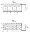
- the fluid 100 is a body fluid and a multiplicity of tiles is loaded with either the same substance with the same or different doses; or different substances with the same or different doses.
- the tiled stent operates to dispense a medicinal substance from a particular tile 90.1 -90.N into the fluid 100 only when that tile 90.1 - 90.N is addressed.
- the tile-controller may be programmed to address particular tiles 90.1 -90.N at the same or at different times, thereby allowing the medicinal substances to be delivered to the body according to a predetermined therapeutic schedule.
Abstract
Description
Claims (13)
- An implantable stent comprising:a tubular member having an interior surface and an exterior surface, characterized in thatat least one of said surfaces is hydrophobic, anda region of said at least one surface includes an array of microstructures or nanostructures that covers first portions of said surface, said array causing the region to have a dynamically controllable hydrophobicity.
- The stent of claim 1, further including a control device affixed to said tubular member for varying said hydrophobicity.
- The stent of claim 2, wherein said control device is remotely actuatable from an external source.
- The stent of claim 1, wherein said array leaves second portions of said surface exposed, and further including a chemically active substance adhered to at least one of said exposed second portions.
- The stent of claim 4, wherein said substance comprises a pharmacological agent or a drug.
- The stent of claim 5, further including a control device affixed to said tubular member, said device being capable of releasing said agent or drug from said at least one second portion.
- The stent of claim 6, further including
an electrically conductive substrate that is configured to be electrically isolated from body fluid in contact with said array of microstructures or nanostructures, and
wherein said control device is capable of applying a voltage between said array and said substrate to vary the penetration of the interstices of said array by said fluid, thereby causing release of said agent or drug into said fluid. - The stent of claim 1, wherein said array leaves second portions of said surface exposed, and further including
means for electrically isolating said array into separate spatial zones,
at least two of said zones containing chemically active substances adhered to the exposed second portions thereof, and
wherein said control device is capable of causing the release of said substances of the separate zones at different times. - The stent of claim 1, further including means for altering the shape of said stent in vivo.
- The stent of claim 1, wherein said tubular member has an elongated slot that is coextensive with its length, thereby forming a pair of elongated edges that are movable relative to one another, and the stent further comprising a plurality of electrically controllable structures thereon, the structures capable of moving said edges and releasably latching said edges.
- An implantable stent comprising
a tubular member having an elongated slot that is coextensive with its length, thereby forming a pair of elongated edges that are movable relative to one another, and
means for changing the diameter of said member by moving said edges relative to one another. - The stent of claim 11, further including means for releasably latching said edges after they have been moved.
- The stent of claim 11, wherein said changing means includes a scratch drive actuator coupled to said edges.
Applications Claiming Priority (2)
| Application Number | Priority Date | Filing Date | Title |
|---|---|---|---|
| US10/798,064 US8915957B2 (en) | 2004-03-11 | 2004-03-11 | Drug delivery stent |
| US798064 | 2004-03-11 |
Publications (3)
| Publication Number | Publication Date |
|---|---|
| EP1574180A2 true EP1574180A2 (en) | 2005-09-14 |
| EP1574180A3 EP1574180A3 (en) | 2005-12-07 |
| EP1574180B1 EP1574180B1 (en) | 2010-10-20 |
Family
ID=34827654
Family Applications (1)
| Application Number | Title | Priority Date | Filing Date |
|---|---|---|---|
| EP05251292A Expired - Fee Related EP1574180B1 (en) | 2004-03-11 | 2005-03-03 | Drug delivery stent |
Country Status (4)
| Country | Link |
|---|---|
| US (1) | US8915957B2 (en) |
| EP (1) | EP1574180B1 (en) |
| JP (1) | JP5004426B2 (en) |
| DE (1) | DE602005024200D1 (en) |
Cited By (3)
| Publication number | Priority date | Publication date | Assignee | Title |
|---|---|---|---|---|
| WO2007134358A1 (en) * | 2006-05-23 | 2007-11-29 | Allvascular Pty Ltd | Endovenous valve transfer stent |
| DE102007032688A1 (en) * | 2007-07-13 | 2009-01-22 | Biotronik Vi Patent Ag | Implant and system of an implant and an excitation device |
| WO2009158336A1 (en) * | 2008-06-25 | 2009-12-30 | Boston Scientific Scimed, Inc. | Medical devices having superhydrophobic surfaces |
Families Citing this family (47)
| Publication number | Priority date | Publication date | Assignee | Title |
|---|---|---|---|---|
| US9107605B2 (en) * | 2000-11-17 | 2015-08-18 | Advanced Bio Prosthetic Surfaces, Ltd., A Wholly Owned Subsidiary Of Palmaz Scientific, Inc. | Device for in vivo delivery of bioactive agents and method of manufacture thereof |
| US20040191127A1 (en) | 2003-03-31 | 2004-09-30 | Avinoam Kornblit | Method and apparatus for controlling the movement of a liquid on a nanostructured or microstructured surface |
| US8124423B2 (en) | 2003-09-30 | 2012-02-28 | Alcatel Lucent | Method and apparatus for controlling the flow resistance of a fluid on nanostructured or microstructured surfaces |
| US7785733B2 (en) * | 2003-11-18 | 2010-08-31 | Alcatel-Lucent Usa Inc. | Reserve cell-array nanostructured battery |
| US7749646B2 (en) * | 2004-03-18 | 2010-07-06 | Alcatel-Lucent Usa Inc. | Reversibly-activated nanostructured battery |
| DE102004017283A1 (en) * | 2004-04-07 | 2005-11-03 | Carl Zeiss | Artificial lens for an eye |
| US9801527B2 (en) | 2004-04-19 | 2017-10-31 | Gearbox, Llc | Lumen-traveling biological interface device |
| US7850676B2 (en) | 2004-04-19 | 2010-12-14 | The Invention Science Fund I, Llc | System with a reservoir for perfusion management |
| US9011329B2 (en) | 2004-04-19 | 2015-04-21 | Searete Llc | Lumenally-active device |
| US8000784B2 (en) | 2004-04-19 | 2011-08-16 | The Invention Science Fund I, Llc | Lumen-traveling device |
| US8361013B2 (en) | 2004-04-19 | 2013-01-29 | The Invention Science Fund I, Llc | Telescoping perfusion management system |
| US8024036B2 (en) | 2007-03-19 | 2011-09-20 | The Invention Science Fund I, Llc | Lumen-traveling biological interface device and method of use |
| US8337482B2 (en) | 2004-04-19 | 2012-12-25 | The Invention Science Fund I, Llc | System for perfusion management |
| US8092549B2 (en) | 2004-09-24 | 2012-01-10 | The Invention Science Fund I, Llc | Ciliated stent-like-system |
| US8353896B2 (en) | 2004-04-19 | 2013-01-15 | The Invention Science Fund I, Llc | Controllable release nasal system |
| US7998060B2 (en) | 2004-04-19 | 2011-08-16 | The Invention Science Fund I, Llc | Lumen-traveling delivery device |
| US7323033B2 (en) * | 2004-04-30 | 2008-01-29 | Lucent Technologies Inc. | Nanostructured surfaces having variable permeability |
| US8118864B1 (en) * | 2004-05-25 | 2012-02-21 | Endovascular Technologies, Inc. | Drug delivery endovascular graft |
| US7608446B2 (en) * | 2004-09-30 | 2009-10-27 | Alcatel-Lucent Usa Inc. | Nanostructured surface for microparticle analysis and manipulation |
| US8734003B2 (en) | 2005-09-15 | 2014-05-27 | Alcatel Lucent | Micro-chemical mixing |
| US8721161B2 (en) | 2005-09-15 | 2014-05-13 | Alcatel Lucent | Fluid oscillations on structured surfaces |
| US20070225800A1 (en) * | 2006-03-24 | 2007-09-27 | Sahatjian Ronald A | Methods and devices having electrically actuatable surfaces |
| US20080058788A1 (en) | 2006-04-12 | 2008-03-06 | Searete Llc., A Limited Liability Corporation Of The State Of Delaware | Autofluorescent imaging and target ablation |
| US9198563B2 (en) | 2006-04-12 | 2015-12-01 | The Invention Science Fund I, Llc | Temporal control of a lumen traveling device in a body tube tree |
| US7449649B2 (en) * | 2006-05-23 | 2008-11-11 | Lucent Technologies Inc. | Liquid switch |
| US7806913B2 (en) * | 2006-08-16 | 2010-10-05 | Depuy Spine, Inc. | Modular multi-level spine stabilization system and method |
| US20080065044A1 (en) | 2006-09-08 | 2008-03-13 | Abbott Cardiovascular Systems Inc. | Bioactive agent-containing implantable rings |
| AU2008244598B8 (en) * | 2007-04-26 | 2012-10-11 | Exxonmobil Upstream Research Company | Method for electromagnetic survey design |
| EP2167152B1 (en) * | 2007-06-13 | 2012-08-01 | Boston Scientific Scimed, Inc. | Anti-migration features and geometry for a shape memory polymer stent |
| US20090076591A1 (en) * | 2007-09-19 | 2009-03-19 | Boston Scientific Scimed, Inc. | Stent Design Allowing Extended Release of Drug and/or Enhanced Adhesion of Polymer to OD Surface |
| JP2012500666A (en) * | 2008-08-22 | 2012-01-12 | ボストン サイエンティフィック サイムド,インコーポレイテッド | Medical device having a coating that releases electromagnetically controlled therapeutic agent |
| US20110153027A1 (en) * | 2009-12-18 | 2011-06-23 | Vysera Biomedical Limited | Drug Delivery System |
| US9526883B2 (en) | 2010-04-28 | 2016-12-27 | Kimberly-Clark Worldwide, Inc. | Composite microneedle array including nanostructures thereon |
| DK2563450T3 (en) | 2010-04-28 | 2017-11-13 | Kimberly Clark Co | Apparatus for administering rheumatoid arthritis drug |
| MX2012012567A (en) | 2010-04-28 | 2012-11-21 | Kimberly Clark Co | Method for increasing permeability of an epithelial barrier. |
| EP2563451B1 (en) | 2010-04-28 | 2017-11-01 | Kimberly-Clark Worldwide, Inc. | MEDICAL DEVICES FOR DELIVERY OF siRNA |
| US8920490B2 (en) * | 2010-05-13 | 2014-12-30 | Boston Scientific Scimed, Inc. | Endoprostheses |
| JP6100271B2 (en) | 2011-10-27 | 2017-03-22 | キンバリー クラーク ワールドワイド インコーポレイテッド | Transdermal delivery of highly viscous bioactive agents |
| DK3542851T3 (en) * | 2011-10-27 | 2022-03-14 | Sorrento Therapeutics Inc | IMPLANTABLE DEVICES FOR DELIVERING BIOACTIVE MEANS |
| US20170246439A9 (en) | 2011-10-27 | 2017-08-31 | Kimberly-Clark Worldwide, Inc. | Increased Bioavailability of Transdermally Delivered Agents |
| TWI469762B (en) * | 2011-11-25 | 2015-01-21 | Ind Tech Res Inst | Electrosurgical unit with micro/nano structures and the manufacturing method thereof |
| EP4052680A1 (en) | 2012-04-06 | 2022-09-07 | Boston Scientific Scimed, Inc. | Anti-migration micropatterned stent coating |
| US9526640B2 (en) | 2013-08-18 | 2016-12-27 | Boston Scientific Scimed, Inc. | Anti-migration micropatterned stent coating |
| CN104853695B (en) | 2013-03-15 | 2017-09-15 | 波士顿科学国际有限公司 | The bracket coating of anti-displacement micro-patterning |
| JP6446471B2 (en) * | 2014-04-02 | 2018-12-26 | ボストン サイエンティフィック サイムド,インコーポレイテッドBoston Scientific Scimed,Inc. | Endoprosthesis and method for producing the same |
| US20220257392A1 (en) * | 2021-02-17 | 2022-08-18 | LionRock Endovascular, Inc. | Devices and Methods for Treating Aneurysms and Other Vascular Conditions |
| WO2023126965A1 (en) * | 2022-01-02 | 2023-07-06 | Nano Therapeutics Private Limited | Directional and temporal release of drugs from medical devices |
Family Cites Families (23)
| Publication number | Priority date | Publication date | Assignee | Title |
|---|---|---|---|---|
| US30379A (en) * | 1860-10-09 | Frank s | ||
| US83646A (en) * | 1868-11-03 | Improvement in stove-pipe thimbles | ||
| US159920A (en) * | 1875-02-16 | Improvement in gage-cocks | ||
| US4718907A (en) * | 1985-06-20 | 1988-01-12 | Atrium Medical Corporation | Vascular prosthesis having fluorinated coating with varying F/C ratio |
| US5716410A (en) | 1993-04-30 | 1998-02-10 | Scimed Life Systems, Inc. | Temporary stent and method of use |
| US5681274A (en) | 1995-03-31 | 1997-10-28 | Boston Scientific Corporation | Variable length uretheral stent |
| US5655548A (en) | 1996-09-16 | 1997-08-12 | Circulation, Inc. | Method for treatment of ischemic heart disease by providing transvenous myocardial perfusion |
| WO1998029030A1 (en) | 1997-01-03 | 1998-07-09 | Biosense Inc. | Pressure-sensing stent |
| JP3791999B2 (en) * | 1997-03-24 | 2006-06-28 | 株式会社アドバンス | Liquid particle handling equipment |
| US5972029A (en) * | 1997-05-13 | 1999-10-26 | Fuisz Technologies Ltd. | Remotely operable stent |
| US5855599A (en) | 1997-09-02 | 1999-01-05 | Sitek, Inc. | Silicon micro machined occlusion implant |
| AU767122B2 (en) * | 1998-06-10 | 2003-10-30 | Georgia Tech Research Corporation | Microneedle devices and methods of manufacture and use thereof |
| US6096175A (en) | 1998-07-17 | 2000-08-01 | Micro Therapeutics, Inc. | Thin film stent |
| US6185961B1 (en) | 1999-01-27 | 2001-02-13 | The United States Of America As Represented By The Secretary Of The Navy | Nanopost arrays and process for making same |
| US6491666B1 (en) * | 1999-11-17 | 2002-12-10 | Microchips, Inc. | Microfabricated devices for the delivery of molecules into a carrier fluid |
| CA2320557A1 (en) | 2000-09-25 | 2002-03-25 | Michelangelo Delfino | Radioactive medical implant and method of manufacturing |
| US8372139B2 (en) | 2001-02-14 | 2013-02-12 | Advanced Bio Prosthetic Surfaces, Ltd. | In vivo sensor and method of making same |
| US7077859B2 (en) | 2000-12-22 | 2006-07-18 | Avantec Vascular Corporation | Apparatus and methods for variably controlled substance delivery from implanted prostheses |
| WO2003018100A1 (en) * | 2001-08-22 | 2003-03-06 | Hasan Semih Oktay | Flexible mems actuated controlled expansion stent |
| WO2003072287A1 (en) | 2002-02-27 | 2003-09-04 | University Of Virginia Patent Foundation | Methods for making implantable medical devices having microstructures |
| AU2003228858A1 (en) | 2002-05-02 | 2003-11-17 | Scimed Life Systems, Inc. | Energetically-controlled delivery of biologically active material from an implanted medical device |
| AU2003270802A1 (en) * | 2002-09-20 | 2004-04-08 | The Children's Hospital Of Philadelphia | Engineering of material surfaces |
| US20050027350A1 (en) * | 2003-07-30 | 2005-02-03 | Biotronik Mess-Und Therapiegeraete Gmbh & Co Ingenieurbuero Berlin | Endovascular implant for the injection of an active substance into the media of a blood vessel |
-
2004
- 2004-03-11 US US10/798,064 patent/US8915957B2/en active Active
-
2005
- 2005-03-03 EP EP05251292A patent/EP1574180B1/en not_active Expired - Fee Related
- 2005-03-03 DE DE602005024200T patent/DE602005024200D1/en active Active
- 2005-03-11 JP JP2005068275A patent/JP5004426B2/en not_active Expired - Fee Related
Non-Patent Citations (1)
| Title |
|---|
| None |
Cited By (5)
| Publication number | Priority date | Publication date | Assignee | Title |
|---|---|---|---|---|
| WO2007134358A1 (en) * | 2006-05-23 | 2007-11-29 | Allvascular Pty Ltd | Endovenous valve transfer stent |
| DE102007032688A1 (en) * | 2007-07-13 | 2009-01-22 | Biotronik Vi Patent Ag | Implant and system of an implant and an excitation device |
| US8337548B2 (en) | 2007-07-13 | 2012-12-25 | Biotronik Vi Patent Ag | Implant and system of an implant and an excitation device |
| WO2009158336A1 (en) * | 2008-06-25 | 2009-12-30 | Boston Scientific Scimed, Inc. | Medical devices having superhydrophobic surfaces |
| US8043359B2 (en) | 2008-06-25 | 2011-10-25 | Boston Scientific Scimed, Inc. | Medical devices having superhydrophobic surfaces |
Also Published As
| Publication number | Publication date |
|---|---|
| US20050203613A1 (en) | 2005-09-15 |
| JP5004426B2 (en) | 2012-08-22 |
| JP2005253982A (en) | 2005-09-22 |
| DE602005024200D1 (en) | 2010-12-02 |
| US8915957B2 (en) | 2014-12-23 |
| EP1574180A3 (en) | 2005-12-07 |
| EP1574180B1 (en) | 2010-10-20 |
Similar Documents
| Publication | Publication Date | Title |
|---|---|---|
| EP1574180B1 (en) | Drug delivery stent | |
| EP2289646B1 (en) | Device to be applied to a biological barrier | |
| US9370628B2 (en) | Wireless microactuators and control methods | |
| AU2003256946B2 (en) | Implantable MEMS medicine delivery system | |
| US20060227513A1 (en) | Controlling biological fluids in microelectromechanical machines | |
| JP2007515195A (en) | MEDICAL DEVICE HAVING MICRO ELECTRO-MACHINE SYSTEM FUNCTION AND METHOD FOR MANUFACTURING THE SAME | |
| US8011316B2 (en) | Systems and methods for producing a medical device | |
| WO2003086631A1 (en) | Temperature controlled microfabricated two-pin liquid sample dispensing system | |
| US20060096078A1 (en) | Device for the actively-controlled and localised deposition of at least one biological solution | |
| US20040020173A1 (en) | Low temperature anodic bonding method using focused energy for assembly of micromachined systems | |
| Vinayakumar et al. | Development of cup shaped microneedle array for transdermal drug delivery | |
| KR101009053B1 (en) | Maintenance and movement system of microrobot for intravascular therapy | |
| Sun et al. | Nanowires for biomedical applications | |
| US20110036153A1 (en) | Test element, system, and method of controlling the wetting of same | |
| NL1015523C1 (en) | Device for manipulating small amounts of liquid, and method for the manufacture thereof. | |
| WO2003000422A1 (en) | Microfabricated two-pin liquid sample dispensing system | |
| EP4001346A1 (en) | Fabrication method of an elastomer with topographical structure formed by the breath figure technique | |
| Antohe et al. | Inkjet Technology and Its Application in Biomedical Coating | |
| Fong | Wireless MEMS drug delivery device enabled by a micromachined Nitinol actuator as a pumping mechanism | |
| EP2765614A1 (en) | Roll-to-roll apparatus and method for manufacturing a product comprising a target substrate provided with at least one foil shaped component | |
| WO2023030933A1 (en) | Implant device with mems (microelectromechanical system) actuated membrane | |
| KR20230139418A (en) | Method for manufacturing three-dimensional microstructures | |
| KR100951796B1 (en) | Method for Coating Substrate using Polymer Stamp |
Legal Events
| Date | Code | Title | Description |
|---|---|---|---|
| PUAI | Public reference made under article 153(3) epc to a published international application that has entered the european phase |
Free format text: ORIGINAL CODE: 0009012 |
|
| 17P | Request for examination filed |
Effective date: 20050319 |
|
| AK | Designated contracting states |
Kind code of ref document: A2 Designated state(s): AT BE BG CH CY CZ DE DK EE ES FI FR GB GR HU IE IS IT LI LT LU MC NL PL PT RO SE SI SK TR |
|
| AX | Request for extension of the european patent |
Extension state: AL BA HR LV MK YU |
|
| PUAL | Search report despatched |
Free format text: ORIGINAL CODE: 0009013 |
|
| AK | Designated contracting states |
Kind code of ref document: A3 Designated state(s): AT BE BG CH CY CZ DE DK EE ES FI FR GB GR HU IE IS IT LI LT LU MC NL PL PT RO SE SI SK TR |
|
| AX | Request for extension of the european patent |
Extension state: AL BA HR LV MK YU |
|
| AKX | Designation fees paid |
Designated state(s): DE FR GB |
|
| 17Q | First examination report despatched |
Effective date: 20080310 |
|
| RAP3 | Party data changed (applicant data changed or rights of an application transferred) |
Owner name: LUCENT TECHNOLOGIES INC. |
|
| GRAP | Despatch of communication of intention to grant a patent |
Free format text: ORIGINAL CODE: EPIDOSNIGR1 |
|
| RIC1 | Information provided on ipc code assigned before grant |
Ipc: A61L 31/14 20060101AFI20100413BHEP Ipc: A61F 2/92 20060101ALI20100413BHEP |
|
| GRAS | Grant fee paid |
Free format text: ORIGINAL CODE: EPIDOSNIGR3 |
|
| GRAA | (expected) grant |
Free format text: ORIGINAL CODE: 0009210 |
|
| AK | Designated contracting states |
Kind code of ref document: B1 Designated state(s): DE FR GB |
|
| REG | Reference to a national code |
Ref country code: GB Ref legal event code: FG4D |
|
| RAP2 | Party data changed (patent owner data changed or rights of a patent transferred) |
Owner name: ALCATEL-LUCENT USA INC. |
|
| REF | Corresponds to: |
Ref document number: 602005024200 Country of ref document: DE Date of ref document: 20101202 Kind code of ref document: P |
|
| PLBE | No opposition filed within time limit |
Free format text: ORIGINAL CODE: 0009261 |
|
| STAA | Information on the status of an ep patent application or granted ep patent |
Free format text: STATUS: NO OPPOSITION FILED WITHIN TIME LIMIT |
|
| 26N | No opposition filed |
Effective date: 20110721 |
|
| REG | Reference to a national code |
Ref country code: DE Ref legal event code: R097 Ref document number: 602005024200 Country of ref document: DE Effective date: 20110721 |
|
| REG | Reference to a national code |
Ref country code: GB Ref legal event code: 732E Free format text: REGISTERED BETWEEN 20131024 AND 20131030 |
|
| REG | Reference to a national code |
Ref country code: FR Ref legal event code: GC Effective date: 20140715 |
|
| REG | Reference to a national code |
Ref country code: FR Ref legal event code: RG Effective date: 20141015 |
|
| REG | Reference to a national code |
Ref country code: FR Ref legal event code: PLFP Year of fee payment: 11 |
|
| REG | Reference to a national code |
Ref country code: FR Ref legal event code: PLFP Year of fee payment: 12 |
|
| PGFP | Annual fee paid to national office [announced via postgrant information from national office to epo] |
Ref country code: GB Payment date: 20160321 Year of fee payment: 12 Ref country code: FR Payment date: 20160321 Year of fee payment: 12 |
|
| PGFP | Annual fee paid to national office [announced via postgrant information from national office to epo] |
Ref country code: DE Payment date: 20160330 Year of fee payment: 12 |
|
| REG | Reference to a national code |
Ref country code: DE Ref legal event code: R119 Ref document number: 602005024200 Country of ref document: DE |
|
| GBPC | Gb: european patent ceased through non-payment of renewal fee |
Effective date: 20170303 |
|
| REG | Reference to a national code |
Ref country code: FR Ref legal event code: ST Effective date: 20171130 |
|
| PG25 | Lapsed in a contracting state [announced via postgrant information from national office to epo] |
Ref country code: DE Free format text: LAPSE BECAUSE OF NON-PAYMENT OF DUE FEES Effective date: 20171003 Ref country code: FR Free format text: LAPSE BECAUSE OF NON-PAYMENT OF DUE FEES Effective date: 20170331 |
|
| PG25 | Lapsed in a contracting state [announced via postgrant information from national office to epo] |
Ref country code: GB Free format text: LAPSE BECAUSE OF NON-PAYMENT OF DUE FEES Effective date: 20170303 |