Field of the Invention
The present invention pertains to the determination of information in a
container track corresponding to a particular time, wherein the container track
includes a plurality of samples. The present invention will be implemented
particularly for identifying user-selectable regions within multiple display frames
Background
Computer technology is continually advancing, providing newer and newer
systems, each more powerful than the previous. These high-performance computer
systems are finding expanded uses in a wide range of personal, business and
academic fields. One such use of high-performance computer technology is in the
area of multimedia. Multimedia refers to providing information to system users via
multiple mediums concurrently. For example, multimedia may include concurrent
presentation of video, audio and textual information. In addition, many multimedia
systems provide for user-interaction, which allows system users to interact with the
information being presented to them.
One disadvantage to multimedia systems, however, is the large amount of data
necessary to generate the presentation. For example, a typical multimedia movie
displayed by a computer system is displayed at a rate of 30 frames per second (fps).
Each frame within the movie can require up to 1.2 megabytes of storage space for a
640x480 resolution display device utilizing 32 bits of color. Thus, a 60-second movie
requires 1300 frames, or up to 2.16 gigabytes of video data. In addition, storage space is
also required for any audio, textual, etc. data being presented concurrently with the
video data, as well as storage space for any other control information for the movie.
Thus, it would be beneficial to provide a system which reduces the amount of data
necessary to display a multimedia movie.
One type of user-interaction currently supported in many non-multimedia
applications is referred to as a "hot spot" or "hot button". A hot button is a region
identified on the display device as being selectable by the user. For example, a hot
button may be a rectangular-shaped region on the screen with the word "help" in the
middle. By moving a pointing device over the hot button with a mouse and
depressing a mouse button, the help hot button is selected by the user. Upon receipt
of this input, the computing system responds by displaying, for example, an index
screen identifying subject headings for which help is available.
The control information required to support hot buttons in a multimedia
movie requires additional storage space within the computer system. Typically,
programs using hot buttons store the data for the hot button in the computer system for
each display frame containing the button. However, due to the storage requirements
of the video and other multimedia presentation data, it would be beneficial to provide
a memory-efficient manner in which to store the necessary control information for
hot buttons in multimedia movies.
Furthermore, user-interaction typically supports multiple user options
concurrently. For example, both a "help" hot button and a "preferences" hot button
may be displayed to the system user. The system's response is thus dependent on
which hot button, if any, is activated by the system user. Thus, it would be beneficial
to provide a system which could display multiple user-selectable regions in a
multimedia movie concurrently and accurately distinguish between regions to
determine which region is selected.
Additionally, it would be advantageous to allow a particular hot button to
cause different responses by the computer system at different points in time. For
example, the help index displayed to the user upon activating the help hot button may
be different depending on when the user selects the hot button. The information to be
displayed by the computer system may change any number of times during the
presentation of the video information, up to and including multiple changes for each
frame. Typically, these changes are supported in the system by storing a separate help
hot button for each frame in which the button occurs. Storing such separate
information, however, requires significant additional storage for the movie. Thus, it
would be beneficial to provide an efficient manner in which to keep track of which of
several actions should be taken by the system upon selection of a hot button.
The present invention provides for these and other advantageous results.
SUMMARY OF THE INVENTION
The present invention provides a method for determining information in a
container track corresponding to a particular time, wherein the container track
includes a plurality of samples, the method comprising the steps of:
In one embodiment, the first sample is a key sample and the second sample is
an override sample. In an alternate embodiment, the adding step (c) comprises adding
the second region and a plurality of children nodes corresponding to the second
region to the merged sample.
In a third alternate embodiment, the method compris es the step of (e) repeating
steps (b) through (d) for each of a plurality of regions of the second sample.
In a last alternate embodiment, the method comprises the steps of:
- identifying a first node of the second region; and
- adding the first node to the merged sample, provided a preceding node in the
first region does not correspond to the first node, otherwise replacing the
preceding node with the first node.
Furthermore, the method compris es the step of repeating the steps of identifying
a first node and adding the first node for a plurality of nodes of the second region.
BRIEF DESCRIPTION OF THE DRAWINGS
The present invention is illustrated by way of example and not limitation in the
figures of the accompanying drawings, in which like references indicate similar
elements and in which:
DETAILED DESCRIPTION
In the following detailed description numerous specific details are set forth in
order to provide a thorough understanding of the present invention. However, it will
be understood by those skilled in the art that the present invention may be practiced
without these specific details. In other instances well known methods, procedures,
components, and circuits have not been described in detail so as not to obscure the
present invention.
Some portions of the detailed descriptions which follow are presented in terms
of algorithms and symbolic representations of operations on data bits within a
computer memory. These algorithmic descriptions and representations are the means
used by those skilled in the data processing arts to most effectively convey the
substance of their work to others skilled in the art. An algorithm is here, and
generally, conceived to be a self-consistent sequence of steps leading to a desired
result. The steps are those requiring physical manipulations of physical quantities.
Usually, though not necessarily, these quantities take the form of electrical or
magnetic signals capable of being stored, transferred, combined, compared, and
otherwise manipulated. It has proven convenient at times, principally for reasons of
common usage, to refer to these signals as bits, values, elements, symbols, characters,
terms, numbers, or the like. It should be borne in mind, however, that all of these and
similar terms are to be associated with the appropriate physical quantities and are
merely convenient labels applied to these quantities. Unless specifically stated
otherwise as apparent from the following discussions, it is appreciated that
throughout the present invention, discussions utilizing terms such as "processing" or
"computing" or "calculating" or "determining" or "displaying" or the like, refer to the
action and processes of a computer system, or similar electronic computing device,
that manipul ates and transforms data represented as physical (electronic) quantities
within the computer system's registers and memories into other data similarly
represented as physical quantities within the computer system memories or registers
or other such information storage, transmission or display devices.
In general, computer systems used by one embodiment of the present invention
as illustrated in block diagram format in Figure 1, comprise a bus 100 for
communicating information, a central processing unit (CPU) 101 coupled with the bus
for processing information and instructions, a random access memory (RAM) 102
coupled with the bus 100 for storing information and instructions for the CPU 101, a
read only memory (ROM) 103 coupled with the bus 100 for storing static information
and instructions for the CPU 101, a data storage device 104 such as a magnetic or
optical disk and disk drive coupled with the bus 100 for storing information (such as
audio or video data) and instructions, a display device 105 coupled to the bus 100 for
displaying information to the computer user, an alphanumeric input device 106
including alphanumeric and function keys coupled to the bus 100 for communicating
information and command selections to the CPU 101, a cursor control device 107
coupled to the bus for communicating user input information and command
selections to the CPU 101, and a signal generating device 108 coupled to the bus 100
for communicating information and instructions to the CPU 101.
In one embodiment of the present invention, signal generating device 108
includes, as an input device, a standard microphone to input audio or voice data to be
processed and stored by the computer system. The signal generation device 108
includes an analog to digital converter to transform analog voice data to digital form
which can be processed by the computer system. In one implementation, signal
generation device 108 also includes a specialized tape cassette player to input stored
voice or audio data to the CPU 101 and the remainder of the system over bus 100. The
signal generation device 108 also includes, as an output, a standard speaker for
realizing the output audio from input signals from the computer system. Signal
generation device 108 also includes well known audio processing hardware to
transform digital audio data to audio signals for output to the speaker, thus creating an
audible output.
The display device 105 utilized with the computer system and the present
invention may be a liquid crystal device, cathode ray tube, or other display device
suitable for creating graphic images and alphanumeric characters (and ideographic
character sets) recognizable to the user. The cursor control device 107 allows the
computer user to dynamically signal the two dimensional movement of a visible
symbol (for example, a pointer or cursor) on a display screen of the display device
105. Many implementations of the cursor control device are known in the art
including a trackball, trackpad, mouse, joystick or special keys on the alphanumeric
input device 106 capable of signaling movement of a given direction or manner of
displacement. It is to be appreciated that the movement of a cursor or pointer also
may be directed and/or activated via input from the keyboard using special keys and
key sequence commands. Alternatively, the cursor may be directed and/or activated
via input from a number of specially adapted cursor directing devices, including those
uniquely developed for the disabled. Alternatively, display device 105 may be a
touchscreen device, where a user can input selections by touching the screen of display
device 105. Additionally, cursor control 107 may also be a three-dimensional input
device which allows the computer user to dynamically signal the three dimensional
movement of a visible symbol. In the discussions regarding cursor movement and/or
activation below, it is to be assumed that the input cursor directing device or push
button may consist of any of those described above and specifically is not limited to
the mouse cursor device.
It is to be appreciated that some of the components shown in Figure 1 may not
be included in systems used by the present invention and that additional components
may be added to the system of Figure 1. For example, a microphone may not be
included within signal generation device 108. Alternatively, additional processors
similar to CPU 101, a digital signal processor(s), or a graphics coprocessor(s) may be
added to the system.
The present invention can operate effectively on a desktop computer system,
such as a Macintosh™ platform available from Apple Computer Inc., of Cupertino,
California. It is to be appreciated, however, that the Apple computer system is only
one of many computer systems that may support the present invention.
In one embodiment, the present Invention is implemented as a series of
software routines run by the computer system of Figure 1. In one implementation,
these software routines are written In the C++ programming language. It is to be
appreciated, however, that these routines may be implemented in any of a wide
variety of programming languages. In an alternate embodiment the present
invention is implemented in discrete hardware or firmware.
The present invention identifies user-selectable regions on a display device. In
the following discussion, a "user-selectable region" refers to any location on a display
device which can be selected by a user. A "hot button" is one such user-selectable
region. A hot button may be displayed as a button on the display device or may be
hidden from view. An example of a displayed hot button is a rectangular button
displayed on a screen with the word "help" displayed within it. By selecting that
button, the user is able to receive whatever help information is associated with the
button. A hidden button, on the other hand, is a region on the display device which
can be selected by the user but which is not explicitly identified as a button. For
example, a hidden button may correspond to the head of an individual or an open
doorway. Although these regions are not specifically identified as buttons to the
system user, the user can still select the regions.
The selection of a hot button by a user may be done in any of a wide variety of
manners. In one embodiment, selection is made by positioning a display pointer over
the region, such as by utilizing a cursor control device, stylus or pen. Once positioned
over the region, the pointer is activated, such as by depressing and releasing (that is,
"clicking") a mouse button. In an alternate embodiment, selection is made by merely
positioning a display pointer over the region; no activation of a mouse or similar
button is necessary. In another alternate embodiment, the display device is a touch-sensitive
screen. In this embodiment, a hot button can be selected by touching the
appropriate location on the screen with, for example, a pen or a finger. In yet another
alternate embodiment the display device is a light-sensitive screen. In this
embodiment, a hot button can be selected by touching the appropriate location on "the
screen with a light pen.
In the following discussion, the term "media sequence" refers to a plurality of
ordered data blocks or frames. A video track, for example, is a media sequence in
which each data block contains video data representing an image. Similarly, a sound
track is a media sequence in which each data block contains audio data representing
sound.
The term "media container" refers to a data structure that includes one or
more media sequences. A QuickTimeTM movie is a media container in that it stores
multiple media sequences, such as video tracks, audio tracks, sound tracks, text tracks,
etc. For additional information on QuickTimeTM movies, refer to Inside Macintosh
QuickTime (Addison-Wesley Publishing Company, Reading Massachusetts, 1993). All
of the media sequences that belong to a media container are sequenced according to a
common time coordinate system.
Media sequences may be either "time-based" or "time-independent". Time-based
media sequences are media sequences in which the progression from one frame
to the next is based on the passage of time. A video track is an example of a time-based
media sequence. During playback, a frame in a video media sequence is
displayed for a set time interval. After the time interval expires, the next frame in the
video media sequence is displayed. This process continues until all of the frames in
the video media sequence have been displayed. The time interval may be modified to
speed up or slow down playback, but the playback timing is still driven by the passage
of time.
A time-independent media sequence is a media sequence in which the
progression from one frame to the next is based on an event other than the passage
of time. For example, consider a media sequence in which each frame contains the
text of a page in a novel. During playback, the page represented in a frame should be
displayed until the reader has completed reading the page. Since reading speeds vary
greatly, the playback mechanism should not display the page associated with the next
frame until the reader indicates a desire to turn the page. Thus, a mechanism may be
provided to the user through which the user may initiate an event to move to the next
page. For example, a user may operate a mouse or other pointing device to click on a
"Turn Page" button to cause the playback mechanism to sequence to the next frame.
In one embodiment, media containers are "slaved" to a clock; that is, the clock
determines when the media sequences that belong to the media container progress
from one frame to the next. All of the media sequences in a typical movie are slaved
to the same clock (the "movie clock") to ensure that the media sequences remain
synchronized during playback. Each cycle of the clock represents a predetermined
time interval for a time-based media sequence. However, cycles of the clock can be
tied to different events (e.g., for a time-independent movie) rather than specific time
intervals.
A sequencing direction is the direction in which a media sequence is played
relative to the order of the frames. Because media sequences are "ordered", all media
sequences have at least two possible sequencing directions. For the purposes of
discussion, these two sequencing directions will be referred to as "forward" and
"backward". However, it should be understood that "forward" does not necessarily
mean the "normal" or "typical" direction, since some applications may process media
sequences in one direction, other applications may process media sequences in the
other direction, and yet other applications may process sequences in either or both
directions.
In one embodiment of the present invention, the mechanism for playing a
movie is implemented through a series of instructions executed on CPU 101 of Figure
1. Initially, the series of instructions may be stored on storage device 104. When the
playback mechanism is invoked, the instructions are copied from storage device 104
into RAM 102, and then accessed and executed by CPU 101.
During execution of the series of instructions, the frames of the media
sequences of a movie are processed by CPU 101 responsive to the series of instructions.
Specifically, CPU 101 causes the frames to be "played". The particular steps for
playing a frame depend on the nature of the data within the frame. For example, a
frame of video data is "played" by causing the image represented in the frame to be
displayed on display device 105. Frames containing audio data are played by
generating the sound represented in the audio frame. Sound may be generated, for
example, on a speaker of signal generation device 108.
CPU 101 sequences through the movie responsive to the series of instructions.
The series of instructions may cause CPU 101 to sequence through the movie
responsive to the passage of time and/or the occurrence of an event. An event which
causes CPU 101 to sequence to the next frame in a media sequence may be a user-actuated
event such as the selection of a key on alphanumeric input device 106, or the
operation of a user-interface control through actuation of cursor control device 107.
Figure 2 shows an example of a movie which may be played on the system of
Figure 1. A movie 200 is shown comprising a video track 205, an audio track 210, and
a container track 215. Video track 205 is a media sequence in which each frame is a
display frame. That is, each frame contains an image for display on a display device.
Audio track 210 is a media sequence in which each frame contains a single frame of
audio data to be played by the system. These sequences of video and audio frames are
sequenced to be played in the forward direction.
Each frame of video track 205 can be any graphical representation of an image.
For example, the frame may be an image of an animated figure, a frame from a series
of computer-generated animation images, a digitized photograph, a combination of
animation and text, etc. It is to be appreciated that although the discussions which
follow discuss video frames, the present invention applies analogously to frames of
animation and other graphical representations which can be displayed.
Container track 215 includes multiple container track frames, also referred to
as "samples", corresponding to the video track 205. Each sample of container track
215 contains control information corresponding to one or more video frames of video
track 205. The control information included within each sample of container track
215 contains the information necessary to identify the location of one or more user-selectable
regions on the display device. In one implementation, multiple samples of
container track 215 can correspond to a single video frame of video track 205. This
may occur, for example, if a single video frame is displayed for more clock cycles of
the movie clock, discussed in more detail below, than the corresponding sample of
container track 215.
Each frame of video track 205 typically corresponds to multiple hot buttons. In
one embodiment of the present invention, movie 200 includes multiple container
tracks 215, each including a different hot button(s) corresponding to video track 205.
In this embodiment, user inputs are compared to the control information stored in
each of the multiple container tracks 215 to determine which region of the display
device, if any, is selected. In an alternate embodiment, movie 200 includes a single
container track 215. In this embodiment, the control information used to identify each
of multiple hot buttons is contained within the single container track 215. In one
implementation, the control information for each of the hot buttons is linked together
utilizing a linked-list structure.
Container track 215 includes two types of frames or samples, referred to as key
samples and override samples. Each frame of video track 205 corresponds to at least
one sample of container track 215. A key sample contains all of the information
necessary to identify a user-selectable region. An override sample contains
information which changes at least one aspect of a user-selectable region defined in
the most recent key sample. By combining the information in the override sample
with the key sample, all of the information necessary to identify the user-selectable
region is available.
In one embodiment, container track 215, audio track 210 and video track 205
are slaved to the same movie clock. Thus, at any given point in time during the
display of movie 200, the system can determine which sample of container track 215
corresponds to the video frame being displayed at that time. It should be noted that,
although the tracks are slaved to the same movie clock, the passage of one clock cycle
or event does not necessarily result in the next sample of container track 215 being the
current sample. As discussed above, each sample of container track 215 can
correspond to one or more video frames. Thus, multiple clock cycles or events may
pass before the next sample becomes the current sample.
In one embodiment of the present invention, key samples are distinguished
from override samples using a key sample table. The key sample table stores a listing
of which time periods of the movie clock correspond to which key samples of
container track 215. Upon receiving a selection from a system user, the system indexes
into the key sample table based on the time according to the movie clock at which the
selection was made. If a particular time period is listed, then the sample corresponding
to the time period is a key sample. If a particular time period is not listed in the table,
then the sample corresponding to the time period is an override sample, and the most
recent key sample is the immediately preceding key sample in the table. The override
sample which corresponds to the video frame can then be determined based on the
time according to the movie clock at which the selection was made. Thus, given any
particular time, the present invention can determine whether the corresponding
sample of container track 215 is a key sample or an override sample. Furthermore, if
the sample is an override sample, the present invention can determine which key
sample is the preceding key sample.
Alternatively, the key sample table may store a listing of video frames rather
than time periods. In this embodiment, the key sample table indicates which video
frames of video track 205 correspond to which key samples of container track 215.
This listing is stored according to the sequence order of the video frames, thereby
allowing the present invention to determine which key samples correspond to video
frames which are displayed prior to and/or subsequent to which other video frames.
In another alternate embodiment of the present Invention, each sample in the
container track 215 includes an identification field. This identification field contains
one of two values; the first value indicates the sample is a key sample and the second
value indicates the sample is an override sample. Thus, in this embodiment a
separate key sample table is not required to determine whether a sample is a key
sample or an override sample.
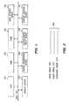
Figure 3A shows two key samples 320 and 350 according to one embodiment of
the present invention. Key sample 320 is shown in a tree form containing M regions
and multiple lower level nodes, also referred to as "children". Similarly, key sample
350 is also shown in a tree form containing N regions and multiple nodes. It is to be
appreciated that key samples 320 and 350 can contain any number of regions. In one
embodiment, key samples 320 and 350 are stored as a data structure (for example, a
linked list) in RAM 102 of Figure 1.
Region 322 is shown as part of key sample 320 and includes a region definition
324, a beginning transformation matrix 326, an ending transformation matrix 328, a
code 330, and a layer indicator 336. Region 322 corresponds to a user-selectable region
defined by key sample 320. In one implementation, region 322 includes a label or
identifier for the user-selectable region which allows subsequent override samples to
alter aspects of the region, as discussed in more detail below.
Given the region definition 324, the beginning transformation matrix 326 and
the code 330, the system is able to identify the user-selectable region and take the
appropriate action if the region is selected by a user. The ending transformation matrix
328 and layer indicator 336 provide further definition and flexibility for the user-selectable
region, as discussed in more detail below. Similarly, region 340 also
contains multiple nodes analogous to those in region 322, including region definition
342, layer 344, etc.
Region definition 324 provides a definition of the user-selectable region. In one
embodiment of the present invention, the definition of a region is a two-dimensional
1-bit mask. That is, the definition indicates which points are part of the user-selectable
region and which points are not. Thus, the region being defined can be any
arbitrary shape. In one embodiment of the present invention, region definition 324 is a
QuickDraw™ region. For additional information on QuickDrawTM regions, refer to
Inside Macintosh Imaging with QuickDraw (Addison-Wesley Publishing Company,
Reading Massachusetts, 1994). In an alternate embodiment region definition 324 is a
QuickDrawTM GX path. In another alternate embodiment, region definition 324 is a
three-dimensional definition of a region to be displayed on a two-dimensional display
device.
The user-selectable region may be defined in any of a wide variety of
conventional manners. In one embodiment the region is defined by identifying only
the points on the outline of the image. That is, the definition includes a list of each
point on the outline of the image, but not on the interior. In an alternate
embodiment, the region is defined by identifying every point for the image. That is,
the definition includes a list of each point of the image, including points located on
the outline and within the area defined by the outline.
Additionally, various resolution levels may be utilized in defining the user-selectable
region. In one implementation, region definition 324 is a high-resolution
definition and the image is scaled down utilizing the beginning transformation
matrix 326. Such an implementation is useful when a description of the region is
available which is of a higher resolution than the resolution capabilities of the display
device. In an alternate implementation, region definition 324 is a low-resolution
definition, and the image is scaled up utilizing the beginning transformation matrix
326. This implementation is useful to save storage space for the region when an exact
display area for the region is not required. For example, given modem screen
resolutions, a selection within one or two pixels of the ideal location is an acceptable
result, providing little (if any) noticeable loss of accuracy.
In an alternate embodiment, region definition 324 provides a three-dimensional
region definition. The region definition is made utilizing any of a wide
variety of conventional modeling techniques. For example, the region definition may
be generated by using three-dimensional modeling techniques for images displayed on
a two-dimensional display device. By way of another example, the region definition
may be generated by using a three-dimensional input device.
Region definition 324 provides an outline of the region based on its own
graphical coordinate system. Region definition 324 does not, in and of itself,
necessarily indicate the area on the display device which the user-selectable region
occupies at any given time. The actual area the region occupies on the display device
is determined by applying the beginning transformation matrix 326 to the region, as
described below. In the descriptions which follow, the region definition is described as
being transformed by a matrix. However, it is to be appreciated that the present
invention can use any of a wide variety of conventional transformation functions to
determine the area the region occupies on the display device, and specifically is not
limited to a matrix.
The
beginning transformation matrix 326, when applied to the
region
definition 324, provides the area that the region occupies on the display device at the
point(s) in time that the container track sample corresponds to the video frame. In
one embodiment of the present invention, the
transformation matrix 326 is a 3-by-3
matrix, such as transformation matrix A shown below.
The area the region occupies on the display device at any particular point in
time is determined by applying the beginning transformation matrix 326 to the two-dimensional
region definition 324. The beginning transformation matrix 326 is
"applied" to the region definition 324 by multiplying each point contained in the
two-dimensional region definition 324 by the beginning transformation matrix 326
using vector multiplication. In one implementation, each point is converted to a 1-by-3
matrix (that is, a 3-element vector), including the x position of the point, the y
position of the point, and a value of 1. By multiplying each point by the beginning
transformation matrix 326, the region definition is mapped to its proper location on
the display device for this video frame.
The beginning transformation matrix 326 allows the region definition to be
mapped to a different location on the screen and to be rotated, flipped, scaled, etc. The
location of the user-selectable region can be translated to a different location on the
screen in the x direction by changing the value of element g of transformation matrix
A. Analogously, the location of the region can be translated to a different location in
the y direction by changing the value of element h of transformation matrix A.
Scaling operations in the x and y directions can be performed by changing the values
of elements a and e, respectively. Values between 0 and 1.0 cause the region to be
scaled down in size, values greater than 1.0 cause the region to be scaled up in size. A
negative value for elements a and e cause the region to be flipped along the x and y
axes, respectively. Rotation operations can be performed by inserting the appropriate
trigonometric functions into elements a, b, d and e of the transformation matrix. For
example, values of cos(), sin(), -sin(), and cos() for elements a, b, d and e,
respectively, cause the region definition to be rotated counterclockwise by an angle .
Once the region definition 324 is mapped to its proper location on the display
device for the video frame, the system can check whether the pixel location selected
by the user is a selection of this hot button. If the pixel location is within the area
defined by the location on the display device for the button, then the button has been
selected. Otherwise, the button has not been selected.
In an alternate embodiment of the present invention, the determination of
whether a selection by a user is for a particular button is performed by applying the
pixel location selected by the user to the inverse of the transformation matrix. By
multiplying the selection by the inverse of the transformation matrix, the pixel
location is mapped into the same graphical coordinate system as the region definition
is in. Thus, the system can determine whether the pixel selected is included within
the region definition.
It is to be appreciated that although the above discussion describes a two-dimensional
region definition and transformation matrix, the present invention
applies analogously to a three-dimensional region definition. The three-dimensional
region definition and corresponding transformation matrix can be generated utilizing
conventional modeling techniques.
Code 330 identifies the action to be performed if the region described in region
definition 324 is selected by a system user. Code 330 as shown contains two lower
level or children nodes, mouse up node 332 and mouse down node 334. Each of these
lower level nodes indicates the action to be taken by the system if that particular event
occurs in the system. In one embodiment of the present invention, each of the nodes
below code 330 indicate a set of instructions stored within the computer system's
memory which are to be executed. These instructions may be stored, for example,
within RAM 102, ROM 103, or storage device 104 of Figure 1. In one implementation,
a node below code 330 indicates a second media container which should be executed
upon selection of the region definition. In an alternate embodiment, a node below
code 330 includes multiple instructions which are to be executed upon selection of the
region.
The number of nodes below code 330 depends on the different system events
which could trigger actions when the region is selected. As shown in Figure 3A, two
system events could trigger actions : a mouse up event and a mouse down event. It is
to be appreciated that any conventional system event could trigger actions, including
cursor or pointer movement events, cursor or pointer location, keyboard actions, etc.
A layer indicator 336 is also optionally included in key sample 320. Layer
indicator 336 provides a value to indicate the depth of an object in relationship to
other objects being displayed. For example, a display screen 400 is shown in Figure 4.
Display screen 400 contains four hot buttons: square 410, circle 420, rectangle 430, and
triangle 440. As shown in Figure 4, triangle 440 overlays rectangle 430; thus, if a user
were to make a selection at the point 450, the computer system should identify triangle
440 as being selected rather than rectangle 430. Layer indicator 336 provides a
solution to this situation. When triangle 440 overlays rectangle 430, triangle 440
contains a higher value in layer indicator 336 than rectangle 430. Correspondingly,
when rectangle 430 overlays triangle 440, rectangle 430 contains a higher value in
layer indicator 336 than triangle 440. Thus, when a user selection is made at point
450, the computer system checks the hot buttons of the highest layer to determine if
the selected point is contained in a hot button of that layer. If a hot button of the
highest layer does contain that point, then the computer system identifies that hot
button as the selected object. However, if a hot button of the highest layer does not
contain that point, then the computer system checks the hot buttons of the next
highest layer to determine if the selected point is contained in a hot button of that
layer. The computer system continues checking layers until a selected button is
identified or no unchecked layers remain.
In an alternate embodiment, when a user selection is made at point 450, the
computer system determines that the point could correspond to either triangle 440 or
rectangle 430. The computer system then determines which of the two objects contains
a higher value in layer indicator 336 and identifies the selected object as the object
having the higher layer indicator.
An ending transformation matrix 328 is also optionally included in region
322. Ending transformation matrix 328, in combination with beginning transformation
matrix 326, allows a single key sample to identify a user-selectable region which
changes over time. The beginning transformation matrix 326 provides the display area
for the region corresponding to the first of the multiple video frames. The ending
transformation matrix 328 provides the display area for the region corresponding to
the last of the multiple video frames. Then, by interpolating between the
beginning transformation matrix 326 and the ending transformation matrix 328,
the display area for the region corresponding to any of the intermediary times
can be determined.
In one embodiment of the present invention, linear interpolation is
used to interpolate between beginning transformation matrix 326 and ending
transformation matrix 328. It is to be appreciated, however, that other types of
interpolation may be used in place of linear interpolation. For example, an
interpolation process may be used which accounts for acceleration of the
region. By way of another example, an interpolation process may be used
which rotates the region a predetermined number of times over a
predetermined duration.
Using two transformation matrices is particularly useful in applications
where the hot button is moving at a constant, known rate, such as in
animation. For example, a sequence of video frames may define movement of
an individual from a beginning location to an ending location in twenty
equally timed steps. If a hot button is associated with the individual, the
beginning transformation matrix corresponds to the beginning location of the
individual and the ending transformation matrix corresponds to the ending
location of the individual, and the area occupied by the hot button in each
intermediary video frame corresponds to an interpolated matrix between the
beginning and ending transformation matrices. Therefore, a hot button for
twenty video frames can be stored requiring only a single region definition for
the button and two transformation matrices.
Thus, by utilizing the two transformation matrices within the same key
sample, movement of the hot button can be represented in a memory-efficient
manner. The system need merely maintain the region definition and the two
transformation matrices to correctly identify the hot button over multiple
video frames.
By way of another example, assume
key sample 320 corresponds to m
video frames in
video track 205 of Figure 3. Further assume that the
beginning
transformation matrix 326 and the ending
transformation matrix 328 are as
shown below:
Given these two matrices, the computer system identifies the area occupied by
the user-selectable region in the first frame by applying
beginning
transformation matrix 326 to the
region definition 324. The area occupied by the
region in frame m is identified by applying ending
transformation matrix 328 to the
region definition 324. The area occupied by the region in frame n, where 1 < n < m is
identified by linearly interpolating between
beginning matrix 326 and ending
matrix
328 to generate a third transformation matrix, and then applying that third
transformation matrix to the
region definition 324. Each scaling or moving element
of the interpolation matrix is determined according to the following calculation.
x i = x'-x m-1 · (n - 1) + x
where x
i is the element of the interpolation matrix being determined, x' is the
corresponding element of the ending transformation matrix, x is the corresponding
element of the beginning transformation matrix, m is the total number of video
frames corresponding to the container track sample, and n is the current video frame
in which the area occupied by the hot button is being determined. Similarly, each
rotational element of the interpolation matrix is generated by using conventional
methods to interpolate between the rotational values in the beginning and ending
matrices, if any.
It is to be appreciated that, due to the nature of the transformation matrices,
any type of movement of the user-selectable region can be accounted for in key sample
320. For example, the movement of the region may be a direct movement from a first
position to a second position with the profile of the region remaining unchanged, such
as a rectangular object being "moved" across the screen. By way of another example,
the region may correspond to the head of an individual being displayed and the
movement of the region may correspond to the rotation of the individual's head,
corresponding element of the beginning transformation matrix, m is the total number
of video frames corresponding to the container track sample, and n is the current
video frame in which the area occupied by the hot button is being determined.
Similarly, each rotational element of the interpolation matrix is generated by using
conventional methods to interpolate between the rotational values in the beginning
and ending matrices, if any.
It is to be appreciated that, due to the nature of the transformation matrices,
any type of movement of the user-selectable region can be accounted for in key sample
320. For example, the movement of the region may be a direct movement from a first
position to a second position with the profile of the region remaining unchanged, such
as a rectangular object being "moved" across the screen. By way of another example,
the region may correspond to the head of an individual being displayed and the
movement of the region may correspond to the rotation of the individual's head,
Thus, hot buttons which are defined utilizing beginning and ending
transformation matrices can be said to have a time duration. This time duration of a
hot button is equal to the amount of time the transformation matrices of the key
sample correspond to the video frame, and can be referenced in terms of the movie
clock time, number of video frames, etc. As discussed above, the key sample can
correspond to an entire video frame, multiple video frames, or only a portion of a
video frame. The sample immediately following a key frame sample is either another
key frame sample which re-defines the hot button, or an override sample which
changes the hot button, as described below.
It is to be appreciated that the interpolation process described above is applicable
to other aspects of a media sequence as well as the transformation matrix. For example,
container track 215 of Figure 2 may include additional key samples and override samples
which correspond to audio track 210. These samples contain node structures analogous to
those shown in Figure 3. One such node could represent, for example, a sound defmition
(analogous to the region definition), with a beginning and ending volume (analogous to
the beginning and ending transformation matrices). Sound volumes between the beginning
and ending volumes could then be generated by interpolating between the two volumes.
The tree structure of Figure 3A also allows multiple nodes of a sample to share
nodes. In one implementation, this is done by having a node contain a pointer to
another node. For example, region definition 342 of region 340 may contain a pointer
to region definition 324 of region 322, thereby allowing a single region definition to be
used for two different user-selectable regions. These two user-selectable regions could
then be placed at different locations on the display device using a different beginning
and/or ending transformation matrix.
By way of another example, multiple regions may share the same region
definition and beginning transformation matrix, but contain different ending
transformation matrices. This is accomplished by generating a region definition node
and beginning transformation matrix node for one of the multiple regions. Then a
pointer to this region definition and this beginning transformation matrix is placed in
the region definition and beginning transformation matrix nodes of the other regions.
Such a system provides efficient storage for identical objects in the frames which
have motion following different paths in the frames. One such example is a series of
video frames starting with a single star in the middle of the display which quickly
breaks into four stars, each of which travels towards a different one of the four corners
of the display device. In this example, a single region definition contains the
definition of the star, a single beginning transformation matrix contains the starting
location of each of the four stars, and four different ending matrices contain the
ending locations of each of the four stars. Intermediate locations for each of the four
stars are generated by interpolating between the corresponding ending transformation
matrices and the beginning transformation matrix.
Key sample 350 is a second key sample in the container track and is analogous
to key sample 320. Key sample 350 includes N regions 352 and 358, each containing
region definitions, transformation matrices, layers, etc. In one embodiment, key sample
350 and key sample 320 each contain a label or an identifier which allows subsequent
override samples to identify which key sample they correspond to.
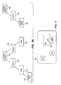
The second type of sample which may be included in container track 215 is an
override sample, shown in Figure 3B. The override sample provides replacement
information for any one or more of the nodes stored in the immediately preceding
key sample. For example, an override sample may contain replacement nodes for one
or both matrices, code sections, or the layer indicator. Additionally, an override sample
may also contain new nodes which did not exist in the preceding key sample (e.g., a
region, a code section for a certain event, or an ending transformation matrix). One
or more override samples may follow a key sample. Two such samples are shown in
Figure 3B as override sample 370 and override sample 382,
Override sample 382 contains an identifier which indicates which of the key
samples in the container track this override sample corresponds to. In the sample
shown in Figure 3B, override sample 382 corresponds to key sample 320 of Figure
3A. Override sample 382 includes region 384 and ending transformation matrix 386.
Region 384 indicates which region from the preceding key sample this override
sample is modifying. Ending transformation matrix 386 provides a new
transformation matrix which is used by the computer system in place of the ending
transformation matrix from the preceding key sample. Thus, if a user selection is
made in a video frame corresponding to override sample 386, an interpolation matrix
is generated by interpolating between beginning matrix 326 of key sample 320 and
ending matrix 386 of override sample 382, and then applying the interpolation matrix
to region definition 324 of key sample 320 to identify the display area for the region. It
will be appreciated that the region definition for a hot button typically requires much
more storage area than that required for a nine-element transformation matrix. Thus,
changes in the display area of the region can be made in a memory-efficient mariner,
requiring storage of only the new transformation matrix rather than repeated storage of
the region definition.
By way of another example, override sample 382 could contain both a beginning
transformation matrix and an ending transformation matrix. If the ending
transformation matrix were a null value, then the single beginning transformation
matrix would replace both beginning matrix 326 and ending matrix 328 of key sample
320. An example of replacing both matrices is a hot button which moves at a constant
rate from a first area to a second area on the display, then jumps to a third area.
Movement of the hot button from the first area to the second area can be represented
by the beginning and ending matrices within key sample 320. The jump to the third
area can be represented by the transformation matrix in the override sample 382,
By way of another example, an additional ending transformation matrix can
also be included in override sample 382. Thus, a hot button may move at a constant
rate from a first area to a second area in one direction on the display, and then move
from the second area to a third area in another direction. This movement can be
represented by two sets of beginning and ending matrices and a single region
definition.
Override sample 370 includes region 372 and region 378, which indicate the
regions of the preceding key sample being modified. Override sample 370 as shown
corresponds to the preceding key sample 320 of Figure 3A. Region 372 includes a code
374 and a mouse up node 376, which provides a replacement code for the immediately
preceding key sample. In override sample 370, mouse up code 374 replaces mouse up
code 332 of key sample 320. Thus, if a user selection is made in a video frame
corresponding to override sample 370, an interpolation matrix is generated based on
beginning matrix 326 and ending matrix 328. The interpolation matrix is then applied
to region definition 324, and if the selection is a mouse up event which corresponds to
the identified area, then mouse up code 376 of override sample 370 is performed rather
than mouse up code 332 of key sample 320. Therefore, the override sample 370
provides a memory-efficient manner in which to change the resultant action from
user-selection of a hot button which does not require repeated storage of either the
region definition or the transformation matrix.
Override sample 370 shows a single code section being updated (that is, code for
a mouse up event). It is to be appreciated, however, that any or all of the different
codes for code 330 can be replaced in an override sample. Similarly, code for
additional events can be added in an override sample even if the preceding key sample
contained no code for those additional events.
Override sample 370 also includes a region 378 and layer indicator 380. Region
378 identifies a second of the M regions from key sample 320 which is being modified
by override sample 370. Layer indicator 380 contains the modification, providing a
new layer value for the preceding key sample.
In one embodiment of the present invention, the override samples following a
key sample build upon one another. That is, when a user-selection is made which
corresponds to an override sample, then any new information in a previous override
sample that is not replaced by information from a subsequent override sample is
combined with the current override sample and the preceding key sample. For
example, assume two override samples follow a key sample and the latter override
sample is the current override sample. If the current override sample contains a
replacement transformation matrix and the preceding override sample contains a
replacement code, then the transformation matrix of the current override sample is
applied to the region definition of the preceding key sample, and if the selected area
matches the current location of the region, then the code in the preceding override
sample is performed. Similarly, a third override sample having a new transformation
matrix could follow these two override samples, and a user-selection corresponding
to this third override sample would result in the transformation matrix from the third
override sample being applied to the region definition of the key sample rather than
the transformation matrix from the second override sample.
In an alternate embodiment, override samples following a key sample do not
build upon one another. That is, if a user-selection is made which corresponds to an
override sample, then the replacement information in that override sample is
combined with the preceding key sample to identify the location of the region,
without regard for any information in interceding override samples.
Thus, the present invention provides a memory-efficient manner in which to
provide hot buttons having time durations and/or changing characteristics. For
example, movie 200 may be a video catalog which displays a showroom and where
the movie pans around the showroom. When a particular item, such as a sofa,
corresponding to a hidden hot button is selected by the user, the user is provided with a
detailed description of the item, such as manufacturer, features, price, etc. Each hot
button corresponding to each of the showroom items need not be repeatedly stored,
only the single region definition for the item is stored along with transformation
matrices indicating the items "movement" as the user pans around the showroom.
By way of another example, movie 200 may be an animated movie of a person
walking across the screen. When a hot button (such as the individual's head) is
selected, the code corresponding to the button is performed. Again, the hot button for
the individual's head requires storing only the original region definition for the head
and the transformation matrices indicating the movement of the individual's head
across the screen.
In one embodiment of the present invention, each user-selectable region
includes an identifying name or key words. Utilizing this identifying information the
present invention can provide improved indexing capabilities for movies. A search
can be performed through the container track for a set of search parameters, such as
the desired identifying name or key words and an associated display area or
movement. For example, a search could be done for all instances where a particular
region corresponding to an individual is moving from left to right, or when the
particular region is in the lower right-hand corner of the display device.
It is to be appreciated that the present invention is applicable to a wide range
of media sequences and is not limited to display frames. For example, the present
invention is applicable to audio frames as well as display frames. In one embodiment,
when samples of the container track correspond to the audio track, the region
definitions of these container track samples identify audio data from the audio track.
The audio data can then be modified by transformation functions (for example, to
alter the volume, to change the pitch, etc.), analogous to the discussion above. User-selection
of the region definition is analogous to the discussion above regarding user-selection
of a display frame, except that the tone does not exist at a particular area of
the display device. Rather, user-selection of the region definition occurs when the user
performs a selecting action (for example, moving the cursor or clicking on a particular
mouse button) when the audio data is being played. The action taken upon user-selection
of the tone depends on the code associated with the region definition,
analogous to the discussion above. Furthermore, different layers can be used to
determine which of multiple sounds being played simultaneously has been selected.
Additionally, different aspects of the regions can be changed using override samples,
analogous to the discussion above.
It is also to be appreciated that the modification of frames using override
samples as discussed above can be used in any of the media sequences and is not
limited to the container track of a movie. For example, the audio frames of an audio
track can contain audio data in a key sample frame which is modified by a subsequent
override sample. This modification is analogous to those discussed above, such as
altering the volume, pitch, etc. of a tone, or changing the layer value of the tone
defined in the key sample.
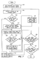
Figure 5 is a flowchart showing the steps followed to identify a user-selectable
region according to one embodiment of the present invention. A selection is first
received from the system user, step 510. As discussed above, a selection may result from
the depressing and release of a mouse button or by simply moving a display pointer
over the selectable region.
The user may make a selection at any time during the display of the media
sequence. Once the selection is made, the present invention accesses the container
track sample corresponding to the time index of the user's selection, step 515. The
time index of a user's selection is the time of the movie clock when the selection is
made. Once the container track sample is determined, the present invention
determines the current transformation matrix for the selected frame, step 520. The
steps followed in determining the current transformation matrix are discussed in more
detail below with reference to Figure 6.
Once the current transformation matrix is determined, the present invention
applies the current transformation matrix to the region definition, step 525. This
region definition is contained in either the preceding key sample or an override
sample. The region definition used is based on the merged sample, which is
generated as discussed below with reference to Figure 7. The present invention then
checks whether the user's selection matches the area the region occupies at the time
of the selection, step 530. If the user's selection matches the area the region occupies,
then the region's code for the system event which constituted selection (e.g., clicking
a mouse button or moving the cursor over the region) is performed, step 535.
Performance of the code, as described above, may include any of a wide variety of
actions, such as displaying additional text on the screen (for example, sale information
for a sofa), or playing a movie.
In an alternate embodiment of the present invention, rather than performing
the region's code in step 535 and ending the process, the present invention continues
to check the user's selection against region locations in the container track(s). Thus,
multiple matches between the user's selection and region locations may be registered
in this embodiment (e.g., due to the regions being in different layers). The present
invention can then perform the code for all of the regions or only select regions (e.g.,
the highest layer, lowest layer, middle layer, etc.).
If the selection does not match the area the region occupies in step 530, then the
present invention determines whether there are any additional regions in the sample,
step 540. If there are additional regions in the sample, then steps 520-540 are repeated
to determine whether the user's selection matches one of the additional regions.
However, if there are not additional regions in the sample, then the present
invention determines whether any additional container tracks exist in the movie, step
545. If additional container tracks exist, then steps 515 through 540 are repeated for
those additional tracks to determine whether a user-selectable region defined within
one of those tracks matches the user's selection.
In one embodiment of the present invention a selection is made by moving a
display pointer over a selectable region, as discussed above. In this embodiment, steps
510-545 are repeated each time the display pointer is moved on the screen to
determine whether a user-selectable region has been selected.
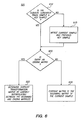
Figure 6 shows the steps followed in determining the current transformation
matrix for a sample, corresponding to step 520 of Figure 5, according to one
embodiment of the present invention. The present invention first checks whether the
current sample is a key sample, step 610. In one implementation, this check is made by
accessing a key sample table, as discussed above. If the sample is not a key sample,
then the current sample and the preceding key sample are merged, step 615. The
merging process generates a merged sample, as discussed in more detail below.
The present invention then checks whether the current sample (or the merged
sample if samples were merged in step 615) contains an ending transformation matrix,
step 620. If there is no ending transformation matrix, then the current matrix is the
beginning matrix of the current (or merged) sample, step 630. However, if there is an
ending transformation matrix, then the current matrix is the interpolation
transformation matrix generated by interpolating between the beginning
transformation matrix and the ending transformation matrix of the current (or
merged) sample, step 625.
Figure 7 shows the steps followed in merging multiple samples according to
one embodiment of the present invention. In one implementation, Figure 7 shows the
steps followed in step 615 of Figure 6. When multiple samples are merged together,
the nodes in subsequent samples replace corresponding nodes in previous samples to
generate a merged sample which represents the container track information
corresponding to the time of the merging. The process starts by adding all of the
nodes from the preceding key sample to a merged sample, step 703, then choosing a
region of the override sample, step 705. The present invention then checks whether the
region chosen in step 705 is in the previous key sample, step 710. If the region is not
in the previous key sample, then the region and all of its children (if any) are added
to the merged sample, step 712. The present invention then checks whether there are
any additional regions in the override sample, step 740. If so, then the present
invention returns to step 705 to choose another region.
Returning to step 710, if the chosen region is in the previous key sample, then
the present invention replaces the corresponding region in the merged sample with
the override sample region, step 715. This can be shown by way of example referring
to Figures 3A and 3B. Key sample 320 contains user-selectable region 322 which is
overridden by region node 372 of override sample 370. Thus, the merged sample
contains region node 372 rather than region node 322.
The present invention then selects a lower level node (that is, one of the
children) of the chosen override sample region node, step 720. A lower level node
refers to any node in the tree of the key sample which is a child, grandchild, great-grandchild,
etc. of the region node. In one implementation, lower level nodes are
selected in a depth-first manner. That is, a child is selected, then all of its children are
selected, then all of its children's children are selected, etc. In an alternate
implementation, lower level nodes are selected in a breadth-first manner. That is, a
child is selected from the children of the region node unt il no such children remain,
then a child is selected from the grandchildren level, etc.
Once a lower level node is selected, the present invention checks whether the
key sample has a node of the same type, step 725. If there are no nodes of the same
type in the key sample, then the present invention adds the node and all of its
children to the merged sample, step 727. The present invention then checks whether
there are any more lower level nodes which have not been selected yet (or added to
the merged sample), step 735. For example, in Figure 3A, override sample 370 contains
code node 374 as a child of region node 372. Thus, code node 330 of key sample 320 is
replaced by code node 374 of override sample 370. However, no other nodes of the
same type exist in override sample 370 for region definition node 324, beginning
transformation matrix 326, ending transformation matrix 328, or layer indicator 336.
However, if the override sample has a node of the same type, then the
corresponding node in the merged sample is replaced by the node in the override
sample, step 730. That is, the override sample node is added to the merged sample
rather than the key sample node. The present invention then checks whether there
are any more lower level nodes which have not been selected (or added to the merged
sample), step 735. If any unselected nodes exist then steps 720 through 735 are
repeated until all such nodes have been selected. Thus, steps 715 through 735 result in
generation of a merged sample which is the original key sample with any nodes
replaced by those which are contained in the override sample.
The present invention then checks whether there are any additional regions
in the previous key sample which have not been checked. If there are additional
regions, then steps 705 through 735 are repeated for these additional regions. Thus,
the merge process as shown in Figure 7 results in a merged sample which contains all
regions of the preceding key sample as modified by the override sample.
Figure 7 as discussed above shows the steps followed to merge a key sample
with an override sample. It is to be appreciated, however, that analogous steps are
performed to merge multiple override samples with a key sample. In one
embodiment, this is accomplished by the present invention checking for the most
recent override sample which has a node of the same type in step 725. In this
embodiment, the node of an override sample that corresponds to a preceding key
sample node replaces that key sample node. However, if multiple override samples
exist which have nodes that correspond to a preceding key sample node, then the
most recent override sample node replaces the key sample node.
Thus, the present invention allows user-selectable regions within multiple
display frames to be identified. The definitions for these user-selectable regions are
stored in a memory-efficient manner, which can include using override samples to
modify key samples and using multiple transformation matrices to identify movement
of a user-selectable region.
Whereas many alterations and modifications of the present invention will be
comprehended by a person skilled in the art after having read the foregoing
description, it is to be understood that the particular embodiments shown and
described by way of illustration are in no way intended to be considered limiting.
Therefore, references to details of particular embodiments are not intended to limit the
scope of the claims, which in themselves recite only those features regarded as
essential to the invention.
Thus, a method and apparatus for identifying user-selectable regions within
multiple display frames has been described.