EP1576979A2 - Nebuliser - Google Patents
Nebuliser Download PDFInfo
- Publication number
- EP1576979A2 EP1576979A2 EP05012609A EP05012609A EP1576979A2 EP 1576979 A2 EP1576979 A2 EP 1576979A2 EP 05012609 A EP05012609 A EP 05012609A EP 05012609 A EP05012609 A EP 05012609A EP 1576979 A2 EP1576979 A2 EP 1576979A2
- Authority
- EP
- European Patent Office
- Prior art keywords
- deflector
- gas
- stream
- profile
- nebuliser according
- Prior art date
- Legal status (The legal status is an assumption and is not a legal conclusion. Google has not performed a legal analysis and makes no representation as to the accuracy of the status listed.)
- Granted
Links
Images


Classifications
-
- B—PERFORMING OPERATIONS; TRANSPORTING
- B05—SPRAYING OR ATOMISING IN GENERAL; APPLYING FLUENT MATERIALS TO SURFACES, IN GENERAL
- B05B—SPRAYING APPARATUS; ATOMISING APPARATUS; NOZZLES
- B05B7/00—Spraying apparatus for discharge of liquids or other fluent materials from two or more sources, e.g. of liquid and air, of powder and gas
- B05B7/0012—Apparatus for achieving spraying before discharge from the apparatus
-
- A—HUMAN NECESSITIES
- A61—MEDICAL OR VETERINARY SCIENCE; HYGIENE
- A61M—DEVICES FOR INTRODUCING MEDIA INTO, OR ONTO, THE BODY; DEVICES FOR TRANSDUCING BODY MEDIA OR FOR TAKING MEDIA FROM THE BODY; DEVICES FOR PRODUCING OR ENDING SLEEP OR STUPOR
- A61M11/00—Sprayers or atomisers specially adapted for therapeutic purposes
- A61M11/001—Particle size control
- A61M11/002—Particle size control by flow deviation causing inertial separation of transported particles
-
- A—HUMAN NECESSITIES
- A61—MEDICAL OR VETERINARY SCIENCE; HYGIENE
- A61M—DEVICES FOR INTRODUCING MEDIA INTO, OR ONTO, THE BODY; DEVICES FOR TRANSDUCING BODY MEDIA OR FOR TAKING MEDIA FROM THE BODY; DEVICES FOR PRODUCING OR ENDING SLEEP OR STUPOR
- A61M11/00—Sprayers or atomisers specially adapted for therapeutic purposes
- A61M11/06—Sprayers or atomisers specially adapted for therapeutic purposes of the injector type
-
- A—HUMAN NECESSITIES
- A61—MEDICAL OR VETERINARY SCIENCE; HYGIENE
- A61M—DEVICES FOR INTRODUCING MEDIA INTO, OR ONTO, THE BODY; DEVICES FOR TRANSDUCING BODY MEDIA OR FOR TAKING MEDIA FROM THE BODY; DEVICES FOR PRODUCING OR ENDING SLEEP OR STUPOR
- A61M15/00—Inhalators
- A61M15/0091—Inhalators mechanically breath-triggered
-
- B—PERFORMING OPERATIONS; TRANSPORTING
- B05—SPRAYING OR ATOMISING IN GENERAL; APPLYING FLUENT MATERIALS TO SURFACES, IN GENERAL
- B05B—SPRAYING APPARATUS; ATOMISING APPARATUS; NOZZLES
- B05B7/00—Spraying apparatus for discharge of liquids or other fluent materials from two or more sources, e.g. of liquid and air, of powder and gas
- B05B7/24—Spraying apparatus for discharge of liquids or other fluent materials from two or more sources, e.g. of liquid and air, of powder and gas with means, e.g. a container, for supplying liquid or other fluent material to a discharge device
- B05B7/2402—Apparatus to be carried on or by a person, e.g. by hand; Apparatus comprising containers fixed to the discharge device
- B05B7/2405—Apparatus to be carried on or by a person, e.g. by hand; Apparatus comprising containers fixed to the discharge device using an atomising fluid as carrying fluid for feeding, e.g. by suction or pressure, a carried liquid from the container to the nozzle
- B05B7/2435—Apparatus to be carried on or by a person, e.g. by hand; Apparatus comprising containers fixed to the discharge device using an atomising fluid as carrying fluid for feeding, e.g. by suction or pressure, a carried liquid from the container to the nozzle the carried liquid and the main stream of atomising fluid being brought together by parallel conduits placed one inside the other
Definitions
- the present invention relates to nebulisers, normally used for administering a medicament to a patient by inspiration, the medicament being atomised into very small droplets or particles.
- a nebuliser comprises a gas exit, an outlet adjacent to the gas exit, and a deflector for deflecting a stream of gas issuing from the gas exit over the outlet for drawing a substance to be atomised from it, and for atomising the substance in the gas.
- the outlet 2 is also adjacent to the gas exit 1, and a deflector 3 is used to deflect the stream of gas issuing from the gas exit 1. as shown in Figure 2.
- the deflector 3 is located in the position shown in Figure 2C. The deflector 3 directs the stream of pressurised gas across the outlet 2 causing atomisation. Once inspiration has ceased, the deflector 3 is raised into the upper part of the housing as shown in Figure 2A.
- a nebuliser comprises a gas exit, at least one outlet adjacent to the gas exit, and a deflector for deflecting a stream of gas issuing from the gas exit over the at least one outlet for drawing a substance to be atomised from it, and atomising the substance in the gas, characterised in that the deflector defines first and second profiles, and in that the atomiser has an atomising configuration in which the first profile of the deflector lies in the stream of gas for atomisation, and a non-atomising configuration in which the second profile of the deflector lies in the stream of gas without atomisation of the substance.
- the atomisation of the substance may be "switched" on and off.
- the deflector includes first and second regions, the first region having the first profile and the second region having the second profile.
- Means for effecting relative movement between the gas exit and the deflector, such that the first region and the second region of the deflector selectively lie in the stream of gas may be included.
- the first region of the deflector can be arranged to lie in the stream of gas during inspiration of a patient, and the second region of the deflector can be arranged to lie in the stream of gas when inspiration is not occurring.
- atomisation will only occur during inspiration, and during exhalation a substance will not be forced into the top of the nebuliser.
- the deflector is movable relative to the gas exit.
- the deflector includes a deflector edge, the edge including the first and second regions. It is also preferred that the edge of the deflector is arc-shaped.
- the deflector comprises first and second elements such that, when the atomiser is in the atomising configuration, the first element is located in the stream of gas and forms the first profile; and, when the atomiser is moved to the non-atomising configuration, the first and second elements move relative to each other so as to form, together, the second profile of the deflector. This means that only one of the elements needs to move in order to "switch" the atomisation on and off.
- a means sensitive to a patient's breathing is included for controlling the relative movement of the elements so that the first profile of the deflector lies in the stream of gas during inspiration of a patient, and a second profile of the deflector lies in the stream of gas when inspiration is not occurring.
- the second element may be a sleeve disposed around at least a substantial part of the first element. The sleeve may project ahead of the first element when the deflector is placed in its second configuration.
- the first element may be a bar, and the second element is movable into position adjacent to the bar. Preferably, this is a position protruding ahead of the bar.
- the second element may be pivotally mounted for movement, and the second element may be positioned at both sides of the bar.
- the second profile of the deflector typically includes edge extensions extending from the extremities of the deflector generally towards the gas exit. These extensions may be of less than one millimetre in length.
- a nebuliser comprises a gas exit: at least one outlet adjacent the gas exit; and a deflector for deflecting a stream of gas issuing from the gas exit over the at least one outlet for drawing a substance to be atomised from it, and for atomising the substance in the gas, characterised in that the deflector is adjustable between an atomising configuration in which the deflector lies in the stream of gas for atomisation, and a non-atomising configuration in which the deflector lies in the stream of the gas to increase the deflection of at least a portion of the stream of gas so that no atomisation occurs.
- the invention is a method of atomising a substance using a deflector for diverting a stream of gas emerging from a gas exit over at least one outlet of the substance characterised by changing the profile of the deflector between a first profile in which atomisation takes place, and a second profile in which atomisation does not occur, but in which the deflector remains in the path of the stream of gas.
- the invention is a method of atomising a substance using a deflector for deflecting a stream of gas emerging from a gas exit over at least one outlet of the substance, characterised by the adjustment of the deflector between an atomising configuration in which the deflector lies in the stream of gas for atomisation, and a non-atomising configuration in which the deflector lies in the stream of gas and increases the deflection of at least a portion of the stream of gas so that no atomisation occurs.
- Figure 3A shows an assembled nebuliser, including a bowl 4 through which passes a gas pipe 5 which defines a gas passage 6. Gas is passed up the gas passage 6 under pressure to a gas exit 7 shown in more detail in Figure 3E.
- a sleeve 8 is disposed around the gas pipe 5 with a space 8a inside it between the sleeve and the gas pipe.
- a space 8b also exists between the lower end of the sleeve 8 and the bowl 4 to allow medicament to enter the space 8a.
- the gas pipe 5 terminates in a head 9 from which the gas emerges under pressure from the gas exit 7. In the top of the head 9, an annular reservoir 10 surrounds the gas exit 7.
- a deflector 15 which is a flat plate-like element shaped as a sector of a circle. At its top-end, it is hinged at a pivot 16 and at its lower end, which has a curved lower edge 17, it lies in the path of the stream of gas emerging from the gas exit 7.
- This lower edge 17 includes two regions shown in Figure 3B as A and B. each of which has a different cross-sectional profile.
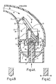
- the cross-sectional profile of region B is shown in Figure 3C, and is generally pointed.
- the cross-sectional profile of region A of the lower edge is shown in Figure 3D, and includes edge extensions 18 which point downwardly generally towards the gas exit 7.
- a flap 19 is carried by the top of the deflector 15 and pivots about the pivot 16 with the deflector 15.
- the flap 19 contains a one-way valve 20 through which air can pass in one direction.
- the flap 19 is also seatable against walls 21 and 22 between which air may pass to and from a vent 23. When the flap 19 is open, air is able to pass from atmosphere through the vent 23 into the mouthpiece 14.
- Figure 3A shows the nebuliser during inspiration by a patient through the mouthpiece 14.
- the inspiration causes a drop in pressure within the mouthpiece 14, causing the flap 19 to open, and ambient air to pass into the nebuliser via the vent 23.
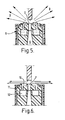
- the opening of the flap 19 causes the deflector 15 to be placed in the position shown in Figure 3A in which region B of the curved lower edge 17 is placed directly in the stream of gas emerging from the gas exit 7. This causes the gas to be deflected, as shown by the arrows D in Figure 5. over the top of the annular reservoir 10. This creates low pressure just above the reservoir 10, thereby drawing the medicament from the bowl 4 into the reservoir via the spaces 8A and 8B.
- the medicament is drawn from the reservoir 10 and is atomised into a fine mist of droplets.
- the deflection of gas by the deflector 15 also causes air to be drawn downwards past the deflector to the region above the head 9, where it entrains the atomised medicament, and then passes downwards beneath the downwardly directed baffle 13 and back up around the outside of the baffle and upwards through the mouthpiece 14 to the patient.
- the flap 19 closes against the walls 21 and 22 and the one-way valve 20 opens allowing the exhaled air to pass freely to atmosphere via the vent 23 as shown by arrows B.
- the closure of the flap 19 causes the deflector 15 to be moved into the position shown in Figure 4A where the stream of gas impacts on the region A of the lower edge 17 shown in Figure 4C. This causes the deflected air to pass over the reservoir 10 in such a manner that the medicament is not drawn up from the bowl 4, and is not atomised by the air as is shown in Figure 6. This is achieved by the edge extensions 18 since no low pressure region is created just above the reservoir 10.
- the deflected air is changed from when it is deflected during inhalation, and at least a portion of the deflected air is deflected through an increased angle and this typically causes the whole of the deflected air to be disrupted and/or deflected through an increased angle to prevent atomisation.
- the deflector 15 moves from the position shown in Figure 3A to the position shown in Figure 4A, the stream of gas continues to be deflected, and is not directed upwardly into the top of the nebuliser, or into the mouthpiece 14.
- the deflector 15 is biassed towards the position shown in Figure 4A so that atomisation only takes place during inspiration.
- the deflector includes a bar 25 which is positioned above the gas exit 7.
- the bar 25 is generally pointed.
- the flap 19 is pivoted about a pivot 16 just as in Figure 3A.
- the flap 19 carries two arms 26 and 27 which swing about the pivot 16 with the flap.
- the arms 26 and 27 are positioned on either side of the bar 25.
- the arms 26 and 27 lie on either side of the part of the bar 25 on which the stream of gas impacts.
- the arms 26 and 27 are a little longer than the edges of the bar 25 as shown in Figures 7B and 7C.
- the deflector is arranged somewhat differently.
- the deflector 30 is circular, or 'pin'-shaped and is retractable into a sleeve 31.
- atomisation takes place, since the stream of gas is deflected over a reservoir 10.
- nebulisation ceases owing to the sleeve 31 projecting downwards further than the deflector 30.
- the deflector 30 deflects the stream of gas, whereas in the top view of Figure 8.
- both the deflector 30 and the sleeve 31 act together to increase the deflection of at least a portion of the deflected gas relative to gas deflected during inhalation.
- the portion of increased deflection gas causes the whole of the deflected gas to be disrupted and/or increased in deflection.
- Figure 9 shows a number of different deflector profiles which might be used to stop atomisation. Clearly, the characteristics of these shapes will vary. It will be noted that most of the shapes includes edge extensions which we presently find need to be no more than 0.5-1.0mm in order to stop atomisation.
- deflector profiles may be used in order to obtain atomisation, including V-shaped bars, wedges, plain bars and various domes, pips and pins.
- Figure 10 is a schematic view showing the head 40 from which a stream of gas emerges. For clarity, the gas exit and the reservoir are not shown. What is shown, however, is the deflector 41 and an envelope 42 of the deflected gas.
- the envelope 42 diverges at an angle of about 30°.
- the lower edge 43 of the envelope 42 is generally horizontal, and causes medicament to be drawn out from the reservoir and atomised into the air.
- the deflector 41 also includes side pieces 44 which typically serve to disrupt and/or increase the deflection of the envelope 42. This destroys any negative pressure just above the medicament outlet. Thus, atomisation does not take place in this position.
- the head 50 is shown from which a stream of gas emerges.
- the deflector 51 is disposed in the path of the stream of gas which emerges from the gas exit, and the deflected gas is indicated generally at 52.
- the deflected gas 52 causes medicament to be drawn out from the reservoir and atomised into the air.
- the deflector 51 is moved downwards towards the gas exit so as to increase the deflection of at least a portion of the deflected air when compared with the deflected air in the first part of Figure 11. This typically causes the whole of the deflected air to be disrupted and/or increased in deflection. This destroys any negative pressure just above the medicament outlet.
- the deflector 51 is moved from a position of about 0.85mm from the gas outlet where atomisation takes place, to a position about 0.1mm from the gas outlet whereby atomisation does not take place. It should be noted that, in this embodiment, the deflector 51 does not actually close the gas exit, but merely disrupts the gas emerging from the exit.
Applications Claiming Priority (3)
| Application Number | Priority Date | Filing Date | Title |
|---|---|---|---|
| GB9804149A GB2334686B (en) | 1998-02-26 | 1998-02-26 | Nebuliser |
| GB9804149 | 1998-02-26 | ||
| EP99300788A EP0938906B1 (en) | 1998-02-26 | 1999-02-03 | Nebuliser |
Related Parent Applications (1)
| Application Number | Title | Priority Date | Filing Date |
|---|---|---|---|
| EP99300788A Division EP0938906B1 (en) | 1998-02-26 | 1999-02-03 | Nebuliser |
Publications (3)
| Publication Number | Publication Date |
|---|---|
| EP1576979A2 true EP1576979A2 (en) | 2005-09-21 |
| EP1576979A3 EP1576979A3 (en) | 2005-12-07 |
| EP1576979B1 EP1576979B1 (en) | 2007-08-15 |
Family
ID=10827673
Family Applications (2)
| Application Number | Title | Priority Date | Filing Date |
|---|---|---|---|
| EP05012609A Expired - Lifetime EP1576979B1 (en) | 1998-02-26 | 1999-02-03 | Nebuliser |
| EP99300788A Expired - Lifetime EP0938906B1 (en) | 1998-02-26 | 1999-02-03 | Nebuliser |
Family Applications After (1)
| Application Number | Title | Priority Date | Filing Date |
|---|---|---|---|
| EP99300788A Expired - Lifetime EP0938906B1 (en) | 1998-02-26 | 1999-02-03 | Nebuliser |
Country Status (9)
| Country | Link |
|---|---|
| US (1) | US6131568A (es) |
| EP (2) | EP1576979B1 (es) |
| AT (2) | ATE369887T1 (es) |
| AU (1) | AU746548B2 (es) |
| CA (1) | CA2262177C (es) |
| DE (2) | DE69928150T2 (es) |
| ES (1) | ES2294596T3 (es) |
| GB (1) | GB2334686B (es) |
| NZ (1) | NZ334321A (es) |
Families Citing this family (37)
| Publication number | Priority date | Publication date | Assignee | Title |
|---|---|---|---|---|
| US5823179A (en) | 1996-02-13 | 1998-10-20 | 1263152 Ontario Inc. | Nebulizer apparatus and method |
| US6044841A (en) * | 1997-08-29 | 2000-04-04 | 1263152 Ontario Inc. | Breath actuated nebulizer with valve assembly having a relief piston |
| NZ504021A (en) * | 1997-10-17 | 2003-04-29 | Systemic Pulmonary Delivery Lt | Method and apparatus for delivering aerosolized medication having air discharged through air tube directly into plume of aerosolized medication |
| DE19962110C2 (de) * | 1999-12-22 | 2003-06-12 | Pari Gmbh | Inhalationsvernebler mit einstückigem Ventilelement |
| CA2826724C (en) | 2000-04-11 | 2016-02-02 | Trudell Medical International | Aerosol delivery apparatus with positive expiratory pressure capacity |
| CA2809180C (en) * | 2001-03-20 | 2015-06-02 | Trudell Medical International | Nebulizer apparatus with an adjustable fluid orifice |
| US7231919B2 (en) * | 2001-09-28 | 2007-06-19 | Kurve Technology, Inc. | Particle dispersion device for nasal delivery |
| US6994083B2 (en) | 2001-12-21 | 2006-02-07 | Trudell Medical International | Nebulizer apparatus and method |
| ITBS20020044U1 (it) * | 2002-04-17 | 2003-10-17 | Flaem Nuova Spa | Ampolla nebulizzatrice con uscita verticale e sistema di antirovesciamento |
| US20030205226A1 (en) | 2002-05-02 | 2003-11-06 | Pre Holding, Inc. | Aerosol medication inhalation system |
| AU2003249623A1 (en) * | 2002-05-09 | 2003-12-12 | Kurve Technology, Inc. | Particle dispersion chamber for nasal nebulizer |
| US6904908B2 (en) | 2002-05-21 | 2005-06-14 | Trudell Medical International | Visual indicator for an aerosol medication delivery apparatus and system |
| US7267120B2 (en) | 2002-08-19 | 2007-09-11 | Allegiance Corporation | Small volume nebulizer |
| CN1812844A (zh) * | 2003-07-04 | 2006-08-02 | 英克罗有限公司 | 喷嘴结构 |
| US7270123B2 (en) * | 2003-08-13 | 2007-09-18 | Trudell Medical International | Nebulizer apparatus and method |
| WO2005023335A2 (en) * | 2003-09-05 | 2005-03-17 | Kurve Technology, Inc. | Integrated nebulizer and particle dispersing chamber for delivery of medicament |
| US20070131230A1 (en) * | 2003-09-05 | 2007-06-14 | Kurve Technology, Inc. | Nasal adapter for the base of the nose |
| CA2557020A1 (en) | 2004-02-24 | 2005-09-01 | Boehringer Ingelheim International Gmbh | Atomiser |
| JP4765526B2 (ja) * | 2005-10-04 | 2011-09-07 | オムロンヘルスケア株式会社 | 吸入器および吸入器用マウスピース |
| EP2043714B1 (en) | 2006-03-30 | 2016-02-10 | CareFusion 2200, Inc. | Nebulizer with pressure-based fluidic-control |
| RU2432190C2 (ru) * | 2006-03-30 | 2011-10-27 | Кэафьюжн 2200, Инк. | Ингалятор со струйным контролем на основе скорости входа и относящиеся к нему способы применения |
| EP2106268B1 (en) * | 2006-08-30 | 2018-12-12 | Kurve Technology, Inc. | Aerosol generating and delivery device |
| JP5674637B2 (ja) * | 2009-02-26 | 2015-02-25 | 中村 正一 | ガスミスト吸入器 |
| US9492625B2 (en) * | 2009-11-12 | 2016-11-15 | Stc.Unm | Dry powder inhaler with flutter dispersion member |
| US8596263B2 (en) * | 2009-11-16 | 2013-12-03 | Samuel David Piper | Inhalation actuated nebulizer with impingement shield |
| WO2012002433A1 (ja) * | 2010-07-01 | 2012-01-05 | 日本エー・シー・ピー株式会社 | ガスミスト吸入器 |
| US10463815B2 (en) | 2012-02-21 | 2019-11-05 | Respira Therapeutics, Inc. | Inhaler to deliver substances for prophylaxis or prevention of disease or injury caused by the inhalation of biological or chemical agents |
| US10525216B2 (en) | 2012-02-21 | 2020-01-07 | Respira Therapeutics, Inc. | Powder dispersion methods and devices |
| US9539408B2 (en) | 2012-10-31 | 2017-01-10 | Trudell Medical International | Nebulizer apparatus |
| CA2922004C (en) * | 2013-09-21 | 2021-11-16 | Inspirx, Inc. | Breath actuated nebulizer |
| ITVR20130279A1 (it) * | 2013-12-12 | 2015-06-13 | Elettroplastica S P A | Dispositivo di nebulizzazione di sostanze per aerosol |
| US10850050B2 (en) | 2016-05-19 | 2020-12-01 | Trudell Medical International | Smart valved holding chamber |
| WO2018007997A1 (en) | 2016-07-08 | 2018-01-11 | Trudell Medical International | Smart oscillating positive expiratory pressure device |
| US10786638B2 (en) | 2016-07-08 | 2020-09-29 | Trudell Medical International | Nebulizer apparatus and method |
| ES2920151T3 (es) | 2016-12-09 | 2022-08-01 | Trudell Medical Int | Nebulizador inteligente |
| MX2020007026A (es) | 2018-01-04 | 2020-12-03 | Trudell Medical Int | Dispositivo de presión espiratoria positiva oscilante inteligente. |
| EP4021542A4 (en) | 2019-08-27 | 2023-09-06 | Trudell Medical International | INTELLIGENT OSCILLATING POSITIVE EXPIRATORY PRESSURE DEVICE |
Citations (5)
| Publication number | Priority date | Publication date | Assignee | Title |
|---|---|---|---|---|
| GB560190A (en) * | 1942-12-04 | 1944-03-23 | Thomas Scott Sutherland | Improved form of atomiser syphon |
| FR1070292A (fr) * | 1953-02-03 | 1954-07-21 | Pulvérisateur | |
| EP0261649A2 (en) * | 1986-09-22 | 1988-03-30 | Omron Tateisi Electronics Co. | Nebulizer |
| EP0711609A2 (en) * | 1994-11-11 | 1996-05-15 | Medic-Aid Limited | Atomizer |
| WO1997029799A2 (en) * | 1996-02-13 | 1997-08-21 | Trudell Medical Limited | Nebulizer apparatus and method |
Family Cites Families (12)
| Publication number | Priority date | Publication date | Assignee | Title |
|---|---|---|---|---|
| GB1138274A (en) * | 1966-03-04 | 1968-12-27 | Liston Fletcher Inc | Therapeutic respirator |
| DE3043377A1 (de) * | 1980-11-17 | 1982-07-01 | Brugger, Inge, 8130 Starnberg | Zerstaeuber |
| US4396015A (en) * | 1980-12-22 | 1983-08-02 | Johnson Robert J | Medication control device for use in treating lungs |
| US4746067A (en) * | 1986-11-07 | 1988-05-24 | Svoboda Steven A | Liquid atomizing device and method |
| FI82808C (fi) * | 1987-12-31 | 1991-04-25 | Etelae Haemeen Keuhkovammayhdi | Ultraljudfinfoerdelningsanordning. |
| US5209225A (en) * | 1991-11-19 | 1993-05-11 | Glenn Joseph G | Flow through nebulizer |
| US5355872B1 (en) * | 1992-03-04 | 1998-10-20 | John H Riggs | Low flow rate nebulizer apparatus and method of nebulization |
| GB9311614D0 (en) * | 1993-06-04 | 1993-07-21 | Aid Medic Ltd | Nebulizer |
| US5503139A (en) * | 1994-02-02 | 1996-04-02 | Mcmahon; Michael D. | Continuous flow adaptor for a nebulizer |
| US5584285A (en) * | 1995-06-07 | 1996-12-17 | Salter Labs | Breathing circuit apparatus for a nebulizer |
| AU1616797A (en) * | 1996-02-15 | 1997-09-02 | Victor Spivak | Multi-element energy focusing |
| US6044841A (en) * | 1997-08-29 | 2000-04-04 | 1263152 Ontario Inc. | Breath actuated nebulizer with valve assembly having a relief piston |
-
1998
- 1998-02-26 GB GB9804149A patent/GB2334686B/en not_active Expired - Fee Related
- 1998-04-08 US US09/057,184 patent/US6131568A/en not_active Expired - Lifetime
-
1999
- 1999-02-03 ES ES05012609T patent/ES2294596T3/es not_active Expired - Lifetime
- 1999-02-03 DE DE69928150T patent/DE69928150T2/de not_active Expired - Lifetime
- 1999-02-03 AT AT05012609T patent/ATE369887T1/de not_active IP Right Cessation
- 1999-02-03 AT AT99300788T patent/ATE309020T1/de not_active IP Right Cessation
- 1999-02-03 EP EP05012609A patent/EP1576979B1/en not_active Expired - Lifetime
- 1999-02-03 EP EP99300788A patent/EP0938906B1/en not_active Expired - Lifetime
- 1999-02-03 DE DE69936895T patent/DE69936895T2/de not_active Expired - Lifetime
- 1999-02-15 AU AU17286/99A patent/AU746548B2/en not_active Ceased
- 1999-02-18 CA CA002262177A patent/CA2262177C/en not_active Expired - Fee Related
- 1999-02-23 NZ NZ334321A patent/NZ334321A/xx not_active IP Right Cessation
Patent Citations (5)
| Publication number | Priority date | Publication date | Assignee | Title |
|---|---|---|---|---|
| GB560190A (en) * | 1942-12-04 | 1944-03-23 | Thomas Scott Sutherland | Improved form of atomiser syphon |
| FR1070292A (fr) * | 1953-02-03 | 1954-07-21 | Pulvérisateur | |
| EP0261649A2 (en) * | 1986-09-22 | 1988-03-30 | Omron Tateisi Electronics Co. | Nebulizer |
| EP0711609A2 (en) * | 1994-11-11 | 1996-05-15 | Medic-Aid Limited | Atomizer |
| WO1997029799A2 (en) * | 1996-02-13 | 1997-08-21 | Trudell Medical Limited | Nebulizer apparatus and method |
Also Published As
| Publication number | Publication date |
|---|---|
| EP0938906A3 (en) | 2000-07-05 |
| EP0938906A2 (en) | 1999-09-01 |
| EP1576979B1 (en) | 2007-08-15 |
| CA2262177C (en) | 2007-09-11 |
| DE69928150D1 (de) | 2005-12-15 |
| GB2334686B (en) | 2002-06-19 |
| DE69936895D1 (de) | 2007-09-27 |
| ATE309020T1 (de) | 2005-11-15 |
| DE69936895T2 (de) | 2008-05-15 |
| GB2334686A (en) | 1999-09-01 |
| GB9804149D0 (en) | 1998-04-22 |
| CA2262177A1 (en) | 1999-08-26 |
| ATE369887T1 (de) | 2007-09-15 |
| AU746548B2 (en) | 2002-05-02 |
| EP0938906B1 (en) | 2005-11-09 |
| EP1576979A3 (en) | 2005-12-07 |
| ES2294596T3 (es) | 2008-04-01 |
| DE69928150T2 (de) | 2006-07-20 |
| NZ334321A (en) | 2000-01-28 |
| AU1728699A (en) | 1999-09-09 |
| US6131568A (en) | 2000-10-17 |
Similar Documents
| Publication | Publication Date | Title |
|---|---|---|
| EP0938906B1 (en) | Nebuliser | |
| CA2162511C (en) | Atomizer with movable deflector | |
| US9907918B2 (en) | Nebulizer apparatus and method | |
| AU739821B2 (en) | Atomizer | |
| RU2432190C2 (ru) | Ингалятор со струйным контролем на основе скорости входа и относящиеся к нему способы применения | |
| WO2005058400A1 (en) | Nasal drug delivery | |
| DE69824327T2 (de) | Inhalationsgerät | |
| CA2568092C (en) | Nebuliser |
Legal Events
| Date | Code | Title | Description |
|---|---|---|---|
| PUAI | Public reference made under article 153(3) epc to a published international application that has entered the european phase |
Free format text: ORIGINAL CODE: 0009012 |
|
| 17P | Request for examination filed |
Effective date: 20050627 |
|
| AC | Divisional application: reference to earlier application |
Ref document number: 0938906 Country of ref document: EP Kind code of ref document: P |
|
| AK | Designated contracting states |
Kind code of ref document: A2 Designated state(s): AT BE CH CY DE DK ES FI FR GB GR IE IT LI LU MC NL PT SE |
|
| AX | Request for extension of the european patent |
Extension state: AL LV MK |
|
| PUAL | Search report despatched |
Free format text: ORIGINAL CODE: 0009013 |
|
| AK | Designated contracting states |
Kind code of ref document: A3 Designated state(s): AT BE CH CY DE DK ES FI FR GB GR IE IT LI LU MC NL PT SE |
|
| AX | Request for extension of the european patent |
Extension state: AL LV MK |
|
| AKX | Designation fees paid |
Designated state(s): AT BE CH CY DE DK ES FI FR GB GR IE IT LI LU MC NL PT SE |
|
| 17Q | First examination report despatched |
Effective date: 20060512 |
|
| GRAP | Despatch of communication of intention to grant a patent |
Free format text: ORIGINAL CODE: EPIDOSNIGR1 |
|
| RAP1 | Party data changed (applicant data changed or rights of an application transferred) |
Owner name: RESPIRONICS (UK) LIMITED |
|
| RBV | Designated contracting states (corrected) |
Designated state(s): AT BE CH CY DE DK ES FI FR GR IE IT LI LU MC NL PT SE |
|
| GRAS | Grant fee paid |
Free format text: ORIGINAL CODE: EPIDOSNIGR3 |
|
| GRAA | (expected) grant |
Free format text: ORIGINAL CODE: 0009210 |
|
| AC | Divisional application: reference to earlier application |
Ref document number: 0938906 Country of ref document: EP Kind code of ref document: P |
|
| AK | Designated contracting states |
Kind code of ref document: B1 Designated state(s): AT BE CH CY DE DK ES FI FR GR IE IT LI LU MC NL PT SE |
|
| REG | Reference to a national code |
Ref country code: CH Ref legal event code: EP |
|
| REG | Reference to a national code |
Ref country code: IE Ref legal event code: FG4D |
|
| REF | Corresponds to: |
Ref document number: 69936895 Country of ref document: DE Date of ref document: 20070927 Kind code of ref document: P |
|
| ET | Fr: translation filed | ||
| PG25 | Lapsed in a contracting state [announced via postgrant information from national office to epo] |
Ref country code: FI Free format text: LAPSE BECAUSE OF FAILURE TO SUBMIT A TRANSLATION OF THE DESCRIPTION OR TO PAY THE FEE WITHIN THE PRESCRIBED TIME-LIMIT Effective date: 20070815 Ref country code: NL Free format text: LAPSE BECAUSE OF FAILURE TO SUBMIT A TRANSLATION OF THE DESCRIPTION OR TO PAY THE FEE WITHIN THE PRESCRIBED TIME-LIMIT Effective date: 20070815 |
|
| NLV1 | Nl: lapsed or annulled due to failure to fulfill the requirements of art. 29p and 29m of the patents act | ||
| PG25 | Lapsed in a contracting state [announced via postgrant information from national office to epo] |
Ref country code: LI Free format text: LAPSE BECAUSE OF FAILURE TO SUBMIT A TRANSLATION OF THE DESCRIPTION OR TO PAY THE FEE WITHIN THE PRESCRIBED TIME-LIMIT Effective date: 20070815 Ref country code: CH Free format text: LAPSE BECAUSE OF FAILURE TO SUBMIT A TRANSLATION OF THE DESCRIPTION OR TO PAY THE FEE WITHIN THE PRESCRIBED TIME-LIMIT Effective date: 20070815 Ref country code: AT Free format text: LAPSE BECAUSE OF FAILURE TO SUBMIT A TRANSLATION OF THE DESCRIPTION OR TO PAY THE FEE WITHIN THE PRESCRIBED TIME-LIMIT Effective date: 20070815 |
|
| REG | Reference to a national code |
Ref country code: CH Ref legal event code: PL |
|
| PG25 | Lapsed in a contracting state [announced via postgrant information from national office to epo] |
Ref country code: BE Free format text: LAPSE BECAUSE OF FAILURE TO SUBMIT A TRANSLATION OF THE DESCRIPTION OR TO PAY THE FEE WITHIN THE PRESCRIBED TIME-LIMIT Effective date: 20070815 |
|
| REG | Reference to a national code |
Ref country code: ES Ref legal event code: FG2A Ref document number: 2294596 Country of ref document: ES Kind code of ref document: T3 |
|
| PG25 | Lapsed in a contracting state [announced via postgrant information from national office to epo] |
Ref country code: DK Free format text: LAPSE BECAUSE OF FAILURE TO SUBMIT A TRANSLATION OF THE DESCRIPTION OR TO PAY THE FEE WITHIN THE PRESCRIBED TIME-LIMIT Effective date: 20070815 Ref country code: GR Free format text: LAPSE BECAUSE OF FAILURE TO SUBMIT A TRANSLATION OF THE DESCRIPTION OR TO PAY THE FEE WITHIN THE PRESCRIBED TIME-LIMIT Effective date: 20071116 |
|
| PG25 | Lapsed in a contracting state [announced via postgrant information from national office to epo] |
Ref country code: PT Free format text: LAPSE BECAUSE OF FAILURE TO SUBMIT A TRANSLATION OF THE DESCRIPTION OR TO PAY THE FEE WITHIN THE PRESCRIBED TIME-LIMIT Effective date: 20080115 |
|
| PLBE | No opposition filed within time limit |
Free format text: ORIGINAL CODE: 0009261 |
|
| STAA | Information on the status of an ep patent application or granted ep patent |
Free format text: STATUS: NO OPPOSITION FILED WITHIN TIME LIMIT |
|
| PG25 | Lapsed in a contracting state [announced via postgrant information from national office to epo] |
Ref country code: SE Free format text: LAPSE BECAUSE OF FAILURE TO SUBMIT A TRANSLATION OF THE DESCRIPTION OR TO PAY THE FEE WITHIN THE PRESCRIBED TIME-LIMIT Effective date: 20071115 |
|
| 26N | No opposition filed |
Effective date: 20080516 |
|
| PG25 | Lapsed in a contracting state [announced via postgrant information from national office to epo] |
Ref country code: MC Free format text: LAPSE BECAUSE OF NON-PAYMENT OF DUE FEES Effective date: 20080228 |
|
| PG25 | Lapsed in a contracting state [announced via postgrant information from national office to epo] |
Ref country code: IE Free format text: LAPSE BECAUSE OF NON-PAYMENT OF DUE FEES Effective date: 20080204 |
|
| PGFP | Annual fee paid to national office [announced via postgrant information from national office to epo] |
Ref country code: ES Payment date: 20090204 Year of fee payment: 11 |
|
| PG25 | Lapsed in a contracting state [announced via postgrant information from national office to epo] |
Ref country code: CY Free format text: LAPSE BECAUSE OF FAILURE TO SUBMIT A TRANSLATION OF THE DESCRIPTION OR TO PAY THE FEE WITHIN THE PRESCRIBED TIME-LIMIT Effective date: 20070815 |
|
| PGFP | Annual fee paid to national office [announced via postgrant information from national office to epo] |
Ref country code: IT Payment date: 20090227 Year of fee payment: 11 |
|
| PG25 | Lapsed in a contracting state [announced via postgrant information from national office to epo] |
Ref country code: LU Free format text: LAPSE BECAUSE OF NON-PAYMENT OF DUE FEES Effective date: 20080203 |
|
| REG | Reference to a national code |
Ref country code: ES Ref legal event code: FD2A Effective date: 20110325 |
|
| PG25 | Lapsed in a contracting state [announced via postgrant information from national office to epo] |
Ref country code: IT Free format text: LAPSE BECAUSE OF NON-PAYMENT OF DUE FEES Effective date: 20100203 |
|
| PG25 | Lapsed in a contracting state [announced via postgrant information from national office to epo] |
Ref country code: ES Free format text: LAPSE BECAUSE OF NON-PAYMENT OF DUE FEES Effective date: 20110314 |
|
| PG25 | Lapsed in a contracting state [announced via postgrant information from national office to epo] |
Ref country code: ES Free format text: LAPSE BECAUSE OF NON-PAYMENT OF DUE FEES Effective date: 20100204 |
|
| REG | Reference to a national code |
Ref country code: FR Ref legal event code: PLFP Year of fee payment: 17 |
|
| PGFP | Annual fee paid to national office [announced via postgrant information from national office to epo] |
Ref country code: FR Payment date: 20150227 Year of fee payment: 17 |
|
| PGFP | Annual fee paid to national office [announced via postgrant information from national office to epo] |
Ref country code: DE Payment date: 20150429 Year of fee payment: 17 |
|
| REG | Reference to a national code |
Ref country code: DE Ref legal event code: R119 Ref document number: 69936895 Country of ref document: DE |
|
| REG | Reference to a national code |
Ref country code: FR Ref legal event code: ST Effective date: 20161028 |
|
| PG25 | Lapsed in a contracting state [announced via postgrant information from national office to epo] |
Ref country code: DE Free format text: LAPSE BECAUSE OF NON-PAYMENT OF DUE FEES Effective date: 20160901 Ref country code: FR Free format text: LAPSE BECAUSE OF NON-PAYMENT OF DUE FEES Effective date: 20160229 |