EP1577776A1 - Method and apparatus for data synchronization in a distributed data base system - Google Patents
Method and apparatus for data synchronization in a distributed data base system Download PDFInfo
- Publication number
- EP1577776A1 EP1577776A1 EP04290733A EP04290733A EP1577776A1 EP 1577776 A1 EP1577776 A1 EP 1577776A1 EP 04290733 A EP04290733 A EP 04290733A EP 04290733 A EP04290733 A EP 04290733A EP 1577776 A1 EP1577776 A1 EP 1577776A1
- Authority
- EP
- European Patent Office
- Prior art keywords
- server
- data base
- clients
- transaction
- data
- Prior art date
- Legal status (The legal status is an assumption and is not a legal conclusion. Google has not performed a legal analysis and makes no representation as to the accuracy of the status listed.)
- Granted
Links
Images

Classifications
-
- G—PHYSICS
- G06—COMPUTING; CALCULATING OR COUNTING
- G06F—ELECTRIC DIGITAL DATA PROCESSING
- G06F16/00—Information retrieval; Database structures therefor; File system structures therefor
- G06F16/20—Information retrieval; Database structures therefor; File system structures therefor of structured data, e.g. relational data
- G06F16/27—Replication, distribution or synchronisation of data between databases or within a distributed database system; Distributed database system architectures therefor
- G06F16/275—Synchronous replication
-
- G—PHYSICS
- G06—COMPUTING; CALCULATING OR COUNTING
- G06F—ELECTRIC DIGITAL DATA PROCESSING
- G06F11/00—Error detection; Error correction; Monitoring
- G06F11/07—Responding to the occurrence of a fault, e.g. fault tolerance
- G06F11/14—Error detection or correction of the data by redundancy in operation
- G06F11/1402—Saving, restoring, recovering or retrying
- G06F11/1474—Saving, restoring, recovering or retrying in transactions
-
- G—PHYSICS
- G06—COMPUTING; CALCULATING OR COUNTING
- G06F—ELECTRIC DIGITAL DATA PROCESSING
- G06F16/00—Information retrieval; Database structures therefor; File system structures therefor
- G06F16/20—Information retrieval; Database structures therefor; File system structures therefor of structured data, e.g. relational data
- G06F16/27—Replication, distribution or synchronisation of data between databases or within a distributed database system; Distributed database system architectures therefor
-
- Y—GENERAL TAGGING OF NEW TECHNOLOGICAL DEVELOPMENTS; GENERAL TAGGING OF CROSS-SECTIONAL TECHNOLOGIES SPANNING OVER SEVERAL SECTIONS OF THE IPC; TECHNICAL SUBJECTS COVERED BY FORMER USPC CROSS-REFERENCE ART COLLECTIONS [XRACs] AND DIGESTS
- Y10—TECHNICAL SUBJECTS COVERED BY FORMER USPC
- Y10S—TECHNICAL SUBJECTS COVERED BY FORMER USPC CROSS-REFERENCE ART COLLECTIONS [XRACs] AND DIGESTS
- Y10S707/00—Data processing: database and file management or data structures
- Y10S707/99931—Database or file accessing
- Y10S707/99939—Privileged access
-
- Y—GENERAL TAGGING OF NEW TECHNOLOGICAL DEVELOPMENTS; GENERAL TAGGING OF CROSS-SECTIONAL TECHNOLOGIES SPANNING OVER SEVERAL SECTIONS OF THE IPC; TECHNICAL SUBJECTS COVERED BY FORMER USPC CROSS-REFERENCE ART COLLECTIONS [XRACs] AND DIGESTS
- Y10—TECHNICAL SUBJECTS COVERED BY FORMER USPC
- Y10S—TECHNICAL SUBJECTS COVERED BY FORMER USPC CROSS-REFERENCE ART COLLECTIONS [XRACs] AND DIGESTS
- Y10S707/00—Data processing: database and file management or data structures
- Y10S707/99951—File or database maintenance
- Y10S707/99952—Coherency, e.g. same view to multiple users
- Y10S707/99955—Archiving or backup
Abstract
Description
- The invention relates to a method of synchronizing a distributed system comprising a server having a master-data base and a set of clients having respective client data bases, as well as a server and a computer program product for executing this method.
- Today's telecommunications system provides a plurality of complexed routing services, for example number portability services, and enhanced services, as IN based information services (IN = Intelligent Network). The telecommunication systems consist of various network elements, for example exchanges, signaling transfer points, service switching points and service control points which are interacting to provide these services to subscribers of the telecommunication system. In such distributed system, service data has to be accessed by various network elements which use different platforms and different data base management systems to administrate their view of the service data. Further, the consistency of the distributed service data has to be kept in such heterogeneous distributed system to ensure a proper provision of the services.
- In such environment it is a problem to keep the data of one or more remote data bases of network elements synchronous to one master-data base, where master-data base and remote data base are located on different platforms and using different data base management systems.
- Caused by customer requirements it is often not possible in such environment to work with remote data base management systems or to store data on the remote system due to the fact that communication is only possible via different protocols. Further, the response time of the remote systems are often about some seconds. To apply a "2-phase" commit algorithm used to ensure the integrity of a committing transaction and sometimes provided by the data base management system is not possible since each data base uses a different data base management system and this functionality is not supported by the communication protocols.
- It is the object of the present invention to provide an improved synchronization of a distributed system comprising a server having a master-data base and a set of clients having respective client data bases.
- The object of the present invention is achieved by a method of synchronizing such distributed system, the method comprising the steps of: incrementally updating client data basics of the clients from the master-data base of the server; maintaining a trace of transaction at the server for recovery; and synchronizing the client data bases in case of a failure by coordinated rollback transactions from the trace. The object of the present invention is further achieved by a server for synchronizing such distributed system, the server having a master-data base, a communication unit for communicating with a set of clients having respective client data bases, and a control unit for incrementally updating client data bases of the clients from the master data base of the server, maintaining a trace of transactions for recovery, and synchronizing the client data bases in case of a failure by coordinated rollback transactions from the trace. The object of the present invention is further achieved by a computer program product for synchronizing such distributed system, the computer program product, when executed by the server, performs the steps of: incrementally updating client data bases of the clients from the master-data base of the server, maintaining a trace of transactions at the server for recovery, and synchronizing the client data base in case of a failure by coordinated rollback transactions from the trace.
- The invention makes it possible to improve the performance and the throughput of the synchronization procedure compared with alternative approaches as long term replication transactions, workflow agents forcing distributed consistencies, lazy updates and incremental updates with locks. It becomes possible to already start the next transaction without waiting on the commitment of the previous transaction. The recovery responsibility is distributed between a mediator of the server and the clients. The mediator maintains a shallow copy of each replication transaction. In case of a failure detection the copy is used to enforce a distributed consistent rollback. The clients maintain the transaction properties within its respective view. This approach is well adapted to the specific constraints and requirements of a telecommunication system with a plurality of interacting network elements, wherein the response times of the remote systems are about some seconds and the use of a common data base management system is not possible due to the use of different platforms and different data base management systems at different network elements. Further, the invention integrates well in such existing telecommunication infrastructure. Therefore, the invention combines higher performant fail save robust operations with minimized integration costs.
- Further advantages are achieved by the embodiments of the invention indicated by the dependent claims.
- Preferably, the invention is applied to the synchronization of service data between a service provisioning system and various signaling transfer points, wherein the synchronization process implements number of portability functions within a telecommunication network. The telecommunication network has different network operators providing their services within the same area. To improve competitiveness between such providers, it is necessary that a subscriber may keep his telephone number when changing from one network operator to another network operator. Therefore, a fixed assignment of number ranges to network operator is not longer possible and exceptions, i.e. a change of a subscriber from one network operator to another network operator, has to be respected within the routing of the telecommunication network. To provide such functionality within a communication network, the routing tables of signaling transfer points of the telecommunication network are modified by the service provisioning system. The service provisioning system keeps a master-data base having the overview about the routing tables of the signaling transfer points. Each of the signaling transfer points has a client data base keeping the respective routing table and representing the view of the respective signaling transfer points. The invention is now applied to execute a change request requesting e.g. the portation of a specific subscriber from one network operator to another network operator. A master-data base of the service provisioning system is changed according to the update requests and the client data bases are incrementally updated according to this change request. The service provisioning system maintains a trace of these transactions and synchronizes the client data bases in case of a failure by coordinated rollback transactions from the trace.
- According to a preferred embodiment of the invention, the server has a mediator which maintains a trace of transactions. When starting a new transaction, the mediator of the server is triggered for maintaining the trace. The mediator stores reference data of the transaction and related meta-information including rollback information and information which clients have to process data of the transaction. Preferably, the mediator stores these data in a persistence replication queue. That concept guarantees high performance, fail save and robust operations.
- When all clients have confirmed the updates related to one request, a commit is done for the changes in the masterdatabase and the mediator(s) are informed about the final commit. Usually there is not transaction oriented interface to the clients but the clients can only perform each change request (e.g. command or CMISE operation; CMISE = Common Management Interaction Service Element) separately. Therefore in the replication queue for each request the actions to do as well as the actions to undo the changes in case of rollback are stored. A request in that sense means a list of change requests which shall be performed within one transaction, i.e. either completely perform all the changes or (if not possible) restore the situation as if no changed would have been done. When a rollback of a request becomes necessary for each operation of the request a client has performed until this time the corresponding undo change request (command or CMISE operation) has to be sent to the client. The latter task is performed by the mediator(s).
- Further, the server preferably removes the data relating to a transaction from the replication queue, if all clients involved in the transaction have returned an acknowledgement message confirming the execution of the respective update of the respective client data base. For example, the mediator removes, after a final commitment, the data associated with the concerned request from the replication queue if all clients have confirmed the execution of all updates corresponding to the request. This approach reduces the memory space that has to be reserved within the server for maintaining a trace of transactions.
- According to a preferred embodiment of the invention, the mediator sends a rollback message to all clients affected, if it detects a failure, e.g. a breakdown of the server, a breakdown of the client or a breakdown of the communication link between the server and the client. Such rollback message can consist of one or a set of single undo change request(s) (commands or CMISE operations) per action sent by the mediator to be undone for rollback of the request. In the following, the client undo the previous changes of the respective client data base indicated by the rollback message. But, it is also possible that the client keeps his own trace and the client uses the information of the rollback message as well as its own trace to undo the previous changes of its respective client data base.
- Preferably, the server accesses the client data bases through associated client data base adapters running on the system platform of the server. Client data base adapters manage a replication of the respective client data base and access the persistence replication-queue storing reference data of consecutive transactions linked with related dedicated meta-data including rollback information and information which client has to process data of the respective transaction. From logical point of view the handling is like there would be one replication queue per client. Physically this replication queues have been compressed into one replication queue by adding a piece of information (bitmap) indicating for which clients a certain entry in the replication queue is valid. The informations in the replication queue are stored in a client independent manner and the said adapters perform the necessary adaptions related to the protocol of the interface to the client (including the command set) and/or the database system of the clients. This approach increases the throughput of the synchronization system as well as reduces the implementation costs necessary for implementing the link with the client data bases.
- These as well as further features and advantages of the invention will be better appreciated by reading the following detailed description of presently preferred exemplary embodiments taken in conjunction with accompanying drawings of which:
- Fig. 1
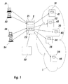
- is a block diagram showing a telecommunication system with a server for synchronizing a distributed system according to the present invention.
- Fig. 2
- shows a block diagram of the server of Fig. 1.
- Fig. 1 shows a telecommunication system with
various terminals 51 to 54, aserver 55, atelecommunication network 1 and aservice provisioning system 2. - The
telecommunication network 1 is a telephone network, e.g. a PSTN or ISDN network (PSTN = Public Switched Telecommunication Network; ISDN = Integrated Services Digital Network). It is possible that thetelecommunication network 1 is a mobile telecommunication network, for example according to the GSM or UMTS standard (GSM = Global System for Mobile Communication; UMTS = Universal Mobile Telecommunications System) or is a telecommunication network which provides mobile and fixed telecommunication services. Thetelecommunication network 1 may be operated by different competing network operators. Further, it is possible that thetelecommunication network 1 is a data network or provides beside telephone services data and video transmission services. - The
telecommunication network 1 is formed by a plurality of different network elements, e.g. exchanges, switches, routers, signaling transfer points, service control points and service switching points. Fig. 1 exemplary shows five network elements of these network elements, namely thenetwork elements - According to the embodiment of Fig. 1, the
network elements 31 to 35 are signaling transfer points of thetelecommunication network 1. But, it is also possible that these network elements are constituted by a mixed set of different network elements of thetelecommunication network 1. - Each of the
network elements 31 to 35 has arespective data base data bases 41 to 45 are managed by at least two different kinds of data base management systems, i.e. we have a heterogeneous data base management system environment. - The
terminals 51 to 54 are operator terminals providing a human machine interface to agents of the network operators administrating thetelecommunication network 1. For example, theterminals 51 to 54 are respectively formed by a computer linked via a local area network with theservice provisioning system 2. - The
server 55 exemplifies a server connected with theservice provisioning system 2 via a data network, wherein theserver 55 automatically generates and/or forwards change requests to theservice provisioning system 2. - The
service provisioning system 2 is constituted by one or several interlinked computers, a software platform and various application programs executed on the system platform formed by the hardware and software platform. The functionalities of theservice provisioning system 2 are performed by the execution of these application programs on the system platform. The application programs controlling in such way the provisioning of the functionalities of theservice provisioning system 2 forms as such or stored on a computer readable storage medium a computer program product for synchronizing a distributed system. - From functional point of view, the
service provisioning system 2 has amaster data base 21 and atrace keeping unit 22. It plays a server role with regard to thenetwork elements 31 to 35 which plays a client role. - The
service provisioning system 2 receives from theterminals 51 to 54 and from theserver 55 change requests requesting the update of service data which are relevant for network element of thetelecommunication network 1. Theservice provisioning system 2 keeps in its master-data base 21 an overview of the service data stored in thedata bases 41 to 45 of thenetwork elements 31 to 35. According to the received change requests, the service provisioning system incrementally updating its master-data base 21 and, in parallel, incrementally updating client data bases of thenetwork elements 31 to 35 effected by the respective change ofmaster data base 21. When starting a new transaction, theservice provisioning system 2 stores the data of the transaction in the master-data base, determines the potential clients of the transaction and contacts the respective ones of thenetwork elements 31 to 35 for updating their respective client data base. Further, it maintains a trace of transactions for recovery. For example, it stores reference data of the transaction and related information including rollback information and information which clients have to process the data of the transactions within thetrace keeping unit 22. - When having successfully executed the respective update of the respective client data base, the
network elements 31 to 35 confirms this execution towards theservice provisioning system 2 by returning a corresponding acknowledgment message. Theservice provisioning system 2 checks, whether all of the network elements contacted for a transaction return such acknowledgment messages. If it detects that all clients involved in the transaction have returned such acknowledgement message, it removes the data relating to the transaction from thetrace keeping unit 22. Further, it commits the change in the master-data base. In case it detects a failure, for example a breakdown of theservice provisioning system 2 or a breakdown of one of the involved network elements, it sends one or a set of undo change requests to all clients affected to undo the previous changes of their respective client data bases. The breakdown of one of thenetwork elements 31 to 35 is for example detected by a watch-dog-timer checking the response time of the acknowledgment messages expected from the involved network elements. - Due to the above-specified mechanism, it is possible to execute further changes in the master-
data base 21 and in the client data bases 41 to 45 without waiting on such final confirmation. Since the response time of thenetwork elements 31 to 35 is in the range of some seconds, a plurality of subsequent change requests may already be executed in the master-data base 21 and in the client data bases 41 to 45, before the execution of the first exchange is finally committed by the system. But, it is still possible to keep the consistency of the distributed system in case of a failure. - In the following, details of the
service provisioning system 2 are exemplified by hand of Fig. 2. - Fig. 2 shows the
service provisioning system 2 and thenetwork elements 31 to 35 with thedata bases 41 to 45. From functional point of view, theservice provisioning system 2 has acontrol unit 23 and acommunication unit 24. - The
communication unit 24 comprises the necessary functionalities for communicating with thenetwork elements 31 to 35. For example, thecommunication unit 24 comprises functionalities for executing the necessary communication protocols, for example the OSI protocol stack or the TCP/IP protocol stack (TCP = Transmission Control Protocol, IP = Internet Protocol). Further, thecommunication unit 24 comprises data base adapters 61 to 65 that comprise the necessary functionalities for remotely accessing data of thedata bases 41 to 45. The data bases 41 to 45 are managed by different data base management systems. For example, the data bases 41 and 42 are managed by a first kind of data base management system, the data bases 43 and 44 are managed by a second kind of data base management system and thedata base 45 is managed by a third kind of data base management system. The data base adapter 61 provides a remote access to thedata base 41 of thenetwork element 31 and thedata base adapter 62 provides a remote access to thedata base 42 of thenetwork element 32, wherein thedata base data base adapters network elements data base adapter 65 provides a remote access to thedata base 45 of thenetwork element 35. - The
control unit 23 comprises amediator 26, adata base control 25, the master-data base 21 and thetrace keeping unit 22 storing a persistent replication queue. - The
data base controller 25 receives change requests from theterminals 51 to 54 and from theserver 55. For example, thedata base controller 25 receives thechange request 7. - When receiving the
change request 7, thedata base controller 25 starts a new transaction and writes the data specified in the change request into themaster data base 21. Further, it determines the potential clients of the transaction and the respective client data changes by means of the data stored in themaster data base 21. When starting the new transaction, thedata base controller 25 further triggers themediator 26. - The
mediator 26 stores reference data of the transaction together with rollback information and the information which client has to process this data in the persistence replication queue of thetrace keeping unit 22 and contacts the potential client of the transaction. For example, it contacts thedata base adapters - The data base adapters 61 to 65 sends the data to its network element to get the result of the respective remote data base management system handling the respective
client data base - The further behavior of the
control unit 23 depends on the messages received from the clients. - If one of the clients has responded a NOK-Message to the
mediator 26, the data base adapters 61 to 65 performs a rollback on its respective data base. Themediator 26 sends rollback messages to all clients, to trigger this procedure. The data base adapters 61 to 65 use the rollback information from the replication queue of thetrace keeping unit 22 to undo all previous changes. - If all clients have responded an OK-message to the
mediator 26, the data base adapters 61 to 65 commit the changes in the master-data base 21. If this was successful, themediator 26 sends a final commitment to all data base adaptors involved to clear theirs resources. The adaptors will then clear their resources related to the concerned transaction. Furthermore the entry in the persistent replication queue will be deleted when all clients have responded an ok message. - If a client has responded that he was unable to deliver the data, the
mediator 26 updates all the meta-information in the replication queue of thetrace keeping unit 22 and keeps the reference data. Otherwise, the whole entry is deleted. If a client reestablishes the connections to the network element later, the data base adapter can send the data from the persistent replication queue to the network element. After the successful update of the client data base of the respective network element, the data base adapter checks the meta-information concerning the point whether it was the last client of all this data. If it was the last one, the data base adapter removes the data from the replication queue of thetrace keeping unit 22. Otherwise, it modifies only the meta-information. - If a failure occurs during the commitment of the master data base, a rollback message is sent to the clients like in the case specified above.
- Due to the long transfer time of the requests from the data base adapters 61 to 65 to the
network elements 31 to 35, it is possible that the system or a single module of the system is going down during one transaction. To prevent inconsistencies caused by the shut-down, different approaches may be used to resynchronizes the master-data base 21 and the client data bases 41 to 45 during startup of each module: - In case the whole system falls down following steps are performed:
- The changes in the master-
data base 21 are rolled back by help of the data base management system of the master-data base 21. If the mediator detects an unfinished request in the replication-queue, it sends rollback messages to all affected clients and the clients undo the changes of the requests in the client data bases 41 to 45. - In case, one or all of the data base adapters 61 to 65 were down, following
steps are performed:
- If the respective data base adapter detects unfinished requests in the data base, the data base adapter queries the dedicated client data base to detect which changes have already been done. Then, the data base adapter finishes the request.
-
Claims (10)
- A method of synchronizing a distributed system comprising a server (2) having a master data base (21) and a set of clients (31 to 35) having respective client data bases (41 to 45), the method comprising the steps of:incrementally updating client data bases (41 to 45) of the clients (31 to 35) from the master-data base (21) of the server (2);maintaining a trace (22) of transactions at the server (2) for recovery; andsynchronizing the client data bases (41 to 45) in case of a failure by coordinated rollback transactions from the trace (22).
- The method of claim 1,
characterized in that the method comprising the further step of triggering, when starting a new transaction, a mediator (26) of the server (2) for maintaining a trace of the transaction, the mediator (26) stores reference data of the transaction and related meta-information including rollback information and information which client has to process data of the transaction. - The method of claim 2,
characterized in that the mediator (26) stores reference data of consecutive transactions linked with related dedicated meta-data including rollback information and information which client has to process data of the respective transaction in a persistent replication queue (22). - The method of claim 1,
characterized in that the server (2) stores, when starting a new transaction, the data of the transaction in the master-data base (21), determines the potential clients (31 to 35) of the transaction and contacts the potential clients (31 to 35) for updating their client data bases. - The method of claim 4,
characterized in that the server (2) sends a final commitment of an update to the clients (31 to 35) involved in a transaction, if all clients (31 to 35) involved in the transaction has returned an acknowledgment message confirming the execution of the respective update of the respective client data base (41 to 45). - The method of claim 3 and claim 4,
characterized in that the server (2) removes the data relating to a transaction from the replication queue (22), if all clients (31 to 35) involved in the transaction have returned an acknowledgment message confirming the execution of the respective update of the respective client data base (41 to 45). - The method of claim 3,
characterized in that, in case of a failure, the mediator (26) sends a rollback message to all clients (31 to 35) affected and the clients use the rollback information from the replication queue (22) to undo the previous changes of their respective client data bases (41 to 45). - The method of claim 1,
characterized in that the method comprising the further step of accessing the client data bases (41 to 45) through associated client data base adapters (61 to 65) of the server (2), the client data base adapters (61 to 65) manages a replication-queue of the respective client data base (41 to 45). - A server (2) for synchronizing a distributed system, in particular a set of signaling transfer points (31 to 35) of a telecommunication network (1), the server (2) comprising a master data base (21), a communication unit for communicating with a set of clients (31 to 35) having respective client data bases (41 to 45), and a control unit (23) for incrementally updating client data bases (41 to 45) of the clients (31 to 35) from the master data base (21) of the server (2), maintaining a trace (22) of transactions for recovery, and synchronizing the client data bases (41 to 45) in case of a failure by coordinated rollback transactions from the trace (22).
- A computer program product for synchronizing a distributed system, in particular a set of signaling transfer points (31 to 35) of a telecommunication network (1), the computer program product comprising a server (2) having a master-data base (21) and a set of clients (31 to 35) having respective client data bases (41 to 45), wherein the computer program product, when executed by the server (2), performs the steps of: incrementally updating client data bases (41 to 45) of the clients (31 to 35) from the master data base (21) of the server (2); maintaining a trace (22) of transactions at the server (2) for recovery; and synchronizing the client data bases (31 to 35) in case of a failure by coordinated rollback transactions from the trace (2).
Priority Applications (4)
| Application Number | Priority Date | Filing Date | Title |
|---|---|---|---|
| DE602004006224T DE602004006224T2 (en) | 2004-03-18 | 2004-03-18 | Method and apparatus for data synchronization of a distributed database system |
| AT04290733T ATE361495T1 (en) | 2004-03-18 | 2004-03-18 | METHOD AND DEVICE FOR DATA SYNCHRONIZING A DISTRIBUTED DATABASE SYSTEM |
| EP04290733A EP1577776B1 (en) | 2004-03-18 | 2004-03-18 | Method and apparatus for data synchronization in a distributed data base system |
| US11/059,477 US7912858B2 (en) | 2004-03-18 | 2005-02-17 | Data synchronization method |
Applications Claiming Priority (1)
| Application Number | Priority Date | Filing Date | Title |
|---|---|---|---|
| EP04290733A EP1577776B1 (en) | 2004-03-18 | 2004-03-18 | Method and apparatus for data synchronization in a distributed data base system |
Publications (2)
| Publication Number | Publication Date |
|---|---|
| EP1577776A1 true EP1577776A1 (en) | 2005-09-21 |
| EP1577776B1 EP1577776B1 (en) | 2007-05-02 |
Family
ID=34833795
Family Applications (1)
| Application Number | Title | Priority Date | Filing Date |
|---|---|---|---|
| EP04290733A Expired - Lifetime EP1577776B1 (en) | 2004-03-18 | 2004-03-18 | Method and apparatus for data synchronization in a distributed data base system |
Country Status (4)
| Country | Link |
|---|---|
| US (1) | US7912858B2 (en) |
| EP (1) | EP1577776B1 (en) |
| AT (1) | ATE361495T1 (en) |
| DE (1) | DE602004006224T2 (en) |
Cited By (1)
| Publication number | Priority date | Publication date | Assignee | Title |
|---|---|---|---|---|
| EP1860563A1 (en) * | 2006-05-26 | 2007-11-28 | Intel Corporation | Sparse checkpoint and rollback |
Families Citing this family (17)
| Publication number | Priority date | Publication date | Assignee | Title |
|---|---|---|---|---|
| US7440985B2 (en) * | 2003-07-31 | 2008-10-21 | Microsoft Corporation | Filtered replication of data stores |
| US7650349B2 (en) * | 2005-01-05 | 2010-01-19 | Microsoft Corporation | Prescribed navigation using topology metadata and navigation path |
| US20070061379A1 (en) * | 2005-09-09 | 2007-03-15 | Frankie Wong | Method and apparatus for sequencing transactions globally in a distributed database cluster |
| US8856091B2 (en) * | 2005-09-09 | 2014-10-07 | Open Invention Network, Llc | Method and apparatus for sequencing transactions globally in distributed database cluster |
| US8332353B2 (en) * | 2007-01-31 | 2012-12-11 | International Business Machines Corporation | Synchronization of dissimilar databases |
| US20090144743A1 (en) * | 2007-11-29 | 2009-06-04 | Microsoft Corporation | Mailbox Configuration Mechanism |
| CN101516131B (en) * | 2008-02-18 | 2012-04-04 | 华为技术有限公司 | Method, system and device for data synchronization |
| US20090319593A1 (en) * | 2008-06-18 | 2009-12-24 | International Business Machines Corporation | Optimized Message Format for Synchronization Flows Between Transaction Processing Systems |
| US8255571B2 (en) * | 2009-06-30 | 2012-08-28 | Apple Inc. | Updating multiple computing devices |
| US9020905B2 (en) * | 2009-10-31 | 2015-04-28 | International Business Machines Corporation | Synchronizing database and non-database resources without a commit coordinator |
| US8630980B2 (en) * | 2010-04-06 | 2014-01-14 | Microsoft Corporation | Synchronization framework that restores a node from backup |
| US20110320530A1 (en) * | 2010-06-29 | 2011-12-29 | International Business Machines Corporation | Method for processing a unit of work |
| US8589553B2 (en) | 2010-09-17 | 2013-11-19 | Microsoft Corporation | Directory leasing |
| US9588858B2 (en) | 2010-11-29 | 2017-03-07 | Ca, Inc. | Periodic data replication |
| US8554729B2 (en) * | 2011-08-31 | 2013-10-08 | Google Inc. | System and method for synchronization of actions in the background of an application |
| CN107590028B (en) * | 2017-09-14 | 2021-05-11 | 广州华多网络科技有限公司 | Information processing method and server |
| US11403319B2 (en) * | 2018-06-01 | 2022-08-02 | Hewlett Packard Enterprise Development Lp | High-availability network device database synchronization |
Citations (3)
| Publication number | Priority date | Publication date | Assignee | Title |
|---|---|---|---|---|
| EP0593062A2 (en) * | 1992-10-16 | 1994-04-20 | Siemens Industrial Automation, Inc. | Redundant networked database system |
| US5530855A (en) * | 1992-10-13 | 1996-06-25 | International Business Machines Corporation | Replicating a database by the sequential application of hierarchically sorted log records |
| US20020116457A1 (en) * | 2001-02-22 | 2002-08-22 | John Eshleman | Systems and methods for managing distributed database resources |
Family Cites Families (19)
| Publication number | Priority date | Publication date | Assignee | Title |
|---|---|---|---|---|
| US5163131A (en) * | 1989-09-08 | 1992-11-10 | Auspex Systems, Inc. | Parallel i/o network file server architecture |
| US5317568A (en) * | 1991-04-11 | 1994-05-31 | Galileo International Partnership | Method and apparatus for managing and facilitating communications in a distributed hetergeneous network |
| JP3593366B2 (en) * | 1994-09-19 | 2004-11-24 | 株式会社日立製作所 | Database management method |
| US5579384A (en) * | 1995-02-17 | 1996-11-26 | Bellsouth Corporation | Telecommunications network service central management system interfacing with protocol specific regional stations providing services to subscribers |
| US5838683A (en) * | 1995-03-13 | 1998-11-17 | Selsius Systems Inc. | Distributed interactive multimedia system architecture |
| US5835904A (en) * | 1995-10-31 | 1998-11-10 | Microsoft Corporation | System and method for implementing database cursors in a client/server environment |
| JPH1013532A (en) * | 1996-06-19 | 1998-01-16 | Fujitsu Ltd | Communication state management system and method in intelligent network |
| US6502133B1 (en) * | 1999-03-25 | 2002-12-31 | Lucent Technologies Inc. | Real-time event processing system with analysis engine using recovery information |
| US7290056B1 (en) * | 1999-09-09 | 2007-10-30 | Oracle International Corporation | Monitoring latency of a network to manage termination of distributed transactions |
| US20020059299A1 (en) * | 2000-07-14 | 2002-05-16 | Frederic Spaey | System and method for synchronizing databases |
| US7209921B2 (en) * | 2000-09-01 | 2007-04-24 | Op40, Inc. | Method and system for deploying an asset over a multi-tiered network |
| US6801921B2 (en) * | 2000-09-08 | 2004-10-05 | Hitachi, Ltd. | Method and system for managing multiple database storage units |
| WO2002059773A1 (en) * | 2000-12-04 | 2002-08-01 | Thinkshare Corp. | Modular distributed mobile data applications |
| US20020156756A1 (en) * | 2000-12-06 | 2002-10-24 | Biosentients, Inc. | Intelligent molecular object data structure and method for application in heterogeneous data environments with high data density and dynamic application needs |
| DE60204940T2 (en) * | 2002-03-27 | 2006-04-20 | Lightmaze Solutions Ag | Intelligent optical network element |
| US6898609B2 (en) * | 2002-05-10 | 2005-05-24 | Douglas W. Kerwin | Database scattering system |
| US20040181510A1 (en) * | 2003-01-16 | 2004-09-16 | Jardin Cary A. | System and method for cooperative database acceleration |
| US20050047350A1 (en) * | 2003-09-03 | 2005-03-03 | Milan Kantor | Apparatus and methods for discovery of network elements in a network |
| ATE369014T1 (en) * | 2004-03-18 | 2007-08-15 | Alcatel Lucent | SERVICE PROVISION SYSTEM |
-
2004
- 2004-03-18 DE DE602004006224T patent/DE602004006224T2/en not_active Expired - Lifetime
- 2004-03-18 EP EP04290733A patent/EP1577776B1/en not_active Expired - Lifetime
- 2004-03-18 AT AT04290733T patent/ATE361495T1/en not_active IP Right Cessation
-
2005
- 2005-02-17 US US11/059,477 patent/US7912858B2/en active Active
Patent Citations (3)
| Publication number | Priority date | Publication date | Assignee | Title |
|---|---|---|---|---|
| US5530855A (en) * | 1992-10-13 | 1996-06-25 | International Business Machines Corporation | Replicating a database by the sequential application of hierarchically sorted log records |
| EP0593062A2 (en) * | 1992-10-16 | 1994-04-20 | Siemens Industrial Automation, Inc. | Redundant networked database system |
| US20020116457A1 (en) * | 2001-02-22 | 2002-08-22 | John Eshleman | Systems and methods for managing distributed database resources |
Cited By (1)
| Publication number | Priority date | Publication date | Assignee | Title |
|---|---|---|---|---|
| EP1860563A1 (en) * | 2006-05-26 | 2007-11-28 | Intel Corporation | Sparse checkpoint and rollback |
Also Published As
| Publication number | Publication date |
|---|---|
| US20050210081A1 (en) | 2005-09-22 |
| ATE361495T1 (en) | 2007-05-15 |
| US7912858B2 (en) | 2011-03-22 |
| DE602004006224D1 (en) | 2007-06-14 |
| DE602004006224T2 (en) | 2008-01-10 |
| EP1577776B1 (en) | 2007-05-02 |
Similar Documents
| Publication | Publication Date | Title |
|---|---|---|
| US7912858B2 (en) | Data synchronization method | |
| AU640029B2 (en) | Distributed data processing systems | |
| JP3075486B2 (en) | How to manage a database network | |
| US20020059279A1 (en) | Apparatus and method for database synchronization in a duplex system | |
| US20020059316A1 (en) | Method and apparatus for improving message availability in a subsystem which supports shared message queues | |
| JP3407016B2 (en) | Network management system | |
| US5966713A (en) | Method for determining the contents of a restoration log | |
| JP2002366381A (en) | Dynamic exchange processing method for object | |
| US6360095B1 (en) | Home location register for a mobile telecommunications network | |
| JPH07114495A (en) | Multiplexing file managing system | |
| AU720380B2 (en) | A home location register for a mobile telecommunications network | |
| US6801617B1 (en) | Method and apparatus for providing data to switching elements in a communications system | |
| CN115297129B (en) | Method and device for establishing data communication network | |
| JP4138329B2 (en) | Data processing system and data processing method | |
| CN112564953B (en) | Method, device and equipment for managing remote equipment of office | |
| KR940007839B1 (en) | Method of processing transaction on real time database management system | |
| Buchholz et al. | Transaction processing in a mobile computing environment with alternating client hosts | |
| KR100359993B1 (en) | Backup method for subscriber's data of home location register | |
| CN114090545A (en) | Method, apparatus, storage medium, and program product for maintaining distributed database | |
| JP2000148563A (en) | System having plurality of server computers | |
| KR0174603B1 (en) | How to restore the database of the exchange | |
| Chipalkatti et al. | A prototype of a service management system for the intelligent network | |
| JPH09237211A (en) | File version number management system | |
| KR940007843B1 (en) | Schema managing method on dbms | |
| JP2002082847A (en) | Computer system, name server and method for answering server address |
Legal Events
| Date | Code | Title | Description |
|---|---|---|---|
| PUAI | Public reference made under article 153(3) epc to a published international application that has entered the european phase |
Free format text: ORIGINAL CODE: 0009012 |
|
| AK | Designated contracting states |
Kind code of ref document: A1 Designated state(s): AT BE BG CH CY CZ DE DK EE ES FI FR GB GR HU IE IT LI LU MC NL PL PT RO SE SI SK TR |
|
| AX | Request for extension of the european patent |
Extension state: AL LT LV MK |
|
| 17P | Request for examination filed |
Effective date: 20051017 |
|
| AKX | Designation fees paid |
Designated state(s): AT BE BG CH CY CZ DE DK EE ES FI FR GB GR HU IE IT LI LU MC NL PL PT RO SE SI SK TR |
|
| GRAP | Despatch of communication of intention to grant a patent |
Free format text: ORIGINAL CODE: EPIDOSNIGR1 |
|
| GRAS | Grant fee paid |
Free format text: ORIGINAL CODE: EPIDOSNIGR3 |
|
| GRAA | (expected) grant |
Free format text: ORIGINAL CODE: 0009210 |
|
| RAP1 | Party data changed (applicant data changed or rights of an application transferred) |
Owner name: ALCATEL LUCENT |
|
| AK | Designated contracting states |
Kind code of ref document: B1 Designated state(s): AT BE BG CH CY CZ DE DK EE ES FI FR GB GR HU IE IT LI LU MC NL PL PT RO SE SI SK TR |
|
| PG25 | Lapsed in a contracting state [announced via postgrant information from national office to epo] |
Ref country code: CH Free format text: LAPSE BECAUSE OF FAILURE TO SUBMIT A TRANSLATION OF THE DESCRIPTION OR TO PAY THE FEE WITHIN THE PRESCRIBED TIME-LIMIT Effective date: 20070502 Ref country code: LI Free format text: LAPSE BECAUSE OF FAILURE TO SUBMIT A TRANSLATION OF THE DESCRIPTION OR TO PAY THE FEE WITHIN THE PRESCRIBED TIME-LIMIT Effective date: 20070502 Ref country code: FI Free format text: LAPSE BECAUSE OF FAILURE TO SUBMIT A TRANSLATION OF THE DESCRIPTION OR TO PAY THE FEE WITHIN THE PRESCRIBED TIME-LIMIT Effective date: 20070502 |
|
| REG | Reference to a national code |
Ref country code: GB Ref legal event code: FG4D |
|
| REG | Reference to a national code |
Ref country code: CH Ref legal event code: EP |
|
| REG | Reference to a national code |
Ref country code: IE Ref legal event code: FG4D |
|
| REF | Corresponds to: |
Ref document number: 602004006224 Country of ref document: DE Date of ref document: 20070614 Kind code of ref document: P |
|
| PG25 | Lapsed in a contracting state [announced via postgrant information from national office to epo] |
Ref country code: SE Free format text: LAPSE BECAUSE OF FAILURE TO SUBMIT A TRANSLATION OF THE DESCRIPTION OR TO PAY THE FEE WITHIN THE PRESCRIBED TIME-LIMIT Effective date: 20070802 |
|
| PG25 | Lapsed in a contracting state [announced via postgrant information from national office to epo] |
Ref country code: ES Free format text: LAPSE BECAUSE OF FAILURE TO SUBMIT A TRANSLATION OF THE DESCRIPTION OR TO PAY THE FEE WITHIN THE PRESCRIBED TIME-LIMIT Effective date: 20070813 |
|
| ET | Fr: translation filed | ||
| NLV1 | Nl: lapsed or annulled due to failure to fulfill the requirements of art. 29p and 29m of the patents act | ||
| REG | Reference to a national code |
Ref country code: CH Ref legal event code: PL |
|
| PG25 | Lapsed in a contracting state [announced via postgrant information from national office to epo] |
Ref country code: PL Free format text: LAPSE BECAUSE OF FAILURE TO SUBMIT A TRANSLATION OF THE DESCRIPTION OR TO PAY THE FEE WITHIN THE PRESCRIBED TIME-LIMIT Effective date: 20070502 Ref country code: AT Free format text: LAPSE BECAUSE OF FAILURE TO SUBMIT A TRANSLATION OF THE DESCRIPTION OR TO PAY THE FEE WITHIN THE PRESCRIBED TIME-LIMIT Effective date: 20070502 |
|
| PG25 | Lapsed in a contracting state [announced via postgrant information from national office to epo] |
Ref country code: BE Free format text: LAPSE BECAUSE OF FAILURE TO SUBMIT A TRANSLATION OF THE DESCRIPTION OR TO PAY THE FEE WITHIN THE PRESCRIBED TIME-LIMIT Effective date: 20070502 |
|
| PG25 | Lapsed in a contracting state [announced via postgrant information from national office to epo] |
Ref country code: DK Free format text: LAPSE BECAUSE OF FAILURE TO SUBMIT A TRANSLATION OF THE DESCRIPTION OR TO PAY THE FEE WITHIN THE PRESCRIBED TIME-LIMIT Effective date: 20070502 Ref country code: NL Free format text: LAPSE BECAUSE OF FAILURE TO SUBMIT A TRANSLATION OF THE DESCRIPTION OR TO PAY THE FEE WITHIN THE PRESCRIBED TIME-LIMIT Effective date: 20070502 Ref country code: BG Free format text: LAPSE BECAUSE OF FAILURE TO SUBMIT A TRANSLATION OF THE DESCRIPTION OR TO PAY THE FEE WITHIN THE PRESCRIBED TIME-LIMIT Effective date: 20070802 Ref country code: PT Free format text: LAPSE BECAUSE OF FAILURE TO SUBMIT A TRANSLATION OF THE DESCRIPTION OR TO PAY THE FEE WITHIN THE PRESCRIBED TIME-LIMIT Effective date: 20071002 Ref country code: SI Free format text: LAPSE BECAUSE OF FAILURE TO SUBMIT A TRANSLATION OF THE DESCRIPTION OR TO PAY THE FEE WITHIN THE PRESCRIBED TIME-LIMIT Effective date: 20070502 Ref country code: CZ Free format text: LAPSE BECAUSE OF FAILURE TO SUBMIT A TRANSLATION OF THE DESCRIPTION OR TO PAY THE FEE WITHIN THE PRESCRIBED TIME-LIMIT Effective date: 20070502 |
|
| PG25 | Lapsed in a contracting state [announced via postgrant information from national office to epo] |
Ref country code: SK Free format text: LAPSE BECAUSE OF FAILURE TO SUBMIT A TRANSLATION OF THE DESCRIPTION OR TO PAY THE FEE WITHIN THE PRESCRIBED TIME-LIMIT Effective date: 20070502 |
|
| PLBE | No opposition filed within time limit |
Free format text: ORIGINAL CODE: 0009261 |
|
| STAA | Information on the status of an ep patent application or granted ep patent |
Free format text: STATUS: NO OPPOSITION FILED WITHIN TIME LIMIT |
|
| 26N | No opposition filed |
Effective date: 20080205 |
|
| PG25 | Lapsed in a contracting state [announced via postgrant information from national office to epo] |
Ref country code: GR Free format text: LAPSE BECAUSE OF FAILURE TO SUBMIT A TRANSLATION OF THE DESCRIPTION OR TO PAY THE FEE WITHIN THE PRESCRIBED TIME-LIMIT Effective date: 20070803 |
|
| PG25 | Lapsed in a contracting state [announced via postgrant information from national office to epo] |
Ref country code: RO Free format text: LAPSE BECAUSE OF FAILURE TO SUBMIT A TRANSLATION OF THE DESCRIPTION OR TO PAY THE FEE WITHIN THE PRESCRIBED TIME-LIMIT Effective date: 20070502 |
|
| PG25 | Lapsed in a contracting state [announced via postgrant information from national office to epo] |
Ref country code: MC Free format text: LAPSE BECAUSE OF NON-PAYMENT OF DUE FEES Effective date: 20080331 |
|
| PG25 | Lapsed in a contracting state [announced via postgrant information from national office to epo] |
Ref country code: IE Free format text: LAPSE BECAUSE OF NON-PAYMENT OF DUE FEES Effective date: 20080318 Ref country code: EE Free format text: LAPSE BECAUSE OF FAILURE TO SUBMIT A TRANSLATION OF THE DESCRIPTION OR TO PAY THE FEE WITHIN THE PRESCRIBED TIME-LIMIT Effective date: 20070502 |
|
| PG25 | Lapsed in a contracting state [announced via postgrant information from national office to epo] |
Ref country code: CY Free format text: LAPSE BECAUSE OF FAILURE TO SUBMIT A TRANSLATION OF THE DESCRIPTION OR TO PAY THE FEE WITHIN THE PRESCRIBED TIME-LIMIT Effective date: 20070502 |
|
| PG25 | Lapsed in a contracting state [announced via postgrant information from national office to epo] |
Ref country code: HU Free format text: LAPSE BECAUSE OF FAILURE TO SUBMIT A TRANSLATION OF THE DESCRIPTION OR TO PAY THE FEE WITHIN THE PRESCRIBED TIME-LIMIT Effective date: 20071103 Ref country code: LU Free format text: LAPSE BECAUSE OF NON-PAYMENT OF DUE FEES Effective date: 20080318 |
|
| PG25 | Lapsed in a contracting state [announced via postgrant information from national office to epo] |
Ref country code: TR Free format text: LAPSE BECAUSE OF FAILURE TO SUBMIT A TRANSLATION OF THE DESCRIPTION OR TO PAY THE FEE WITHIN THE PRESCRIBED TIME-LIMIT Effective date: 20070502 |
|
| REG | Reference to a national code |
Ref country code: GB Ref legal event code: 732E Free format text: REGISTERED BETWEEN 20130926 AND 20131002 |
|
| REG | Reference to a national code |
Ref country code: FR Ref legal event code: GC Effective date: 20131018 |
|
| REG | Reference to a national code |
Ref country code: FR Ref legal event code: RG Effective date: 20141016 |
|
| REG | Reference to a national code |
Ref country code: FR Ref legal event code: PLFP Year of fee payment: 12 |
|
| REG | Reference to a national code |
Ref country code: FR Ref legal event code: CA Effective date: 20150521 |
|
| REG | Reference to a national code |
Ref country code: FR Ref legal event code: CA Effective date: 20150521 |
|
| REG | Reference to a national code |
Ref country code: FR Ref legal event code: PLFP Year of fee payment: 13 |
|
| REG | Reference to a national code |
Ref country code: FR Ref legal event code: PLFP Year of fee payment: 14 |
|
| REG | Reference to a national code |
Ref country code: FR Ref legal event code: PLFP Year of fee payment: 15 |
|
| PGFP | Annual fee paid to national office [announced via postgrant information from national office to epo] |
Ref country code: DE Payment date: 20190305 Year of fee payment: 16 |
|
| PGFP | Annual fee paid to national office [announced via postgrant information from national office to epo] |
Ref country code: IT Payment date: 20200221 Year of fee payment: 17 |
|
| PGFP | Annual fee paid to national office [announced via postgrant information from national office to epo] |
Ref country code: FR Payment date: 20200214 Year of fee payment: 17 |
|
| REG | Reference to a national code |
Ref country code: DE Ref legal event code: R119 Ref document number: 602004006224 Country of ref document: DE |
|
| PG25 | Lapsed in a contracting state [announced via postgrant information from national office to epo] |
Ref country code: DE Free format text: LAPSE BECAUSE OF NON-PAYMENT OF DUE FEES Effective date: 20201001 |
|
| GBPC | Gb: european patent ceased through non-payment of renewal fee |
Effective date: 20200318 |
|
| PG25 | Lapsed in a contracting state [announced via postgrant information from national office to epo] |
Ref country code: GB Free format text: LAPSE BECAUSE OF NON-PAYMENT OF DUE FEES Effective date: 20200318 |
|
| PG25 | Lapsed in a contracting state [announced via postgrant information from national office to epo] |
Ref country code: FR Free format text: LAPSE BECAUSE OF NON-PAYMENT OF DUE FEES Effective date: 20210331 |
|
| PG25 | Lapsed in a contracting state [announced via postgrant information from national office to epo] |
Ref country code: IT Free format text: LAPSE BECAUSE OF NON-PAYMENT OF DUE FEES Effective date: 20210318 |