EP1579733B1 - Color temperature correction for phosphor converted leds - Google Patents
Color temperature correction for phosphor converted leds Download PDFInfo
- Publication number
- EP1579733B1 EP1579733B1 EP03777121A EP03777121A EP1579733B1 EP 1579733 B1 EP1579733 B1 EP 1579733B1 EP 03777121 A EP03777121 A EP 03777121A EP 03777121 A EP03777121 A EP 03777121A EP 1579733 B1 EP1579733 B1 EP 1579733B1
- Authority
- EP
- European Patent Office
- Prior art keywords
- led
- current signal
- modulation
- color
- emission spectra
- Prior art date
- Legal status (The legal status is an assumption and is not a legal conclusion. Google has not performed a legal analysis and makes no representation as to the accuracy of the status listed.)
- Expired - Lifetime
Links
- OAICVXFJPJFONN-UHFFFAOYSA-N Phosphorus Chemical compound [P] OAICVXFJPJFONN-UHFFFAOYSA-N 0.000 title claims abstract description 50
- 238000000295 emission spectrum Methods 0.000 claims abstract description 29
- 238000000034 method Methods 0.000 claims abstract description 29
- 230000008569 process Effects 0.000 claims description 10
- 230000002596 correlated effect Effects 0.000 claims description 5
- 230000008878 coupling Effects 0.000 claims description 2
- 238000010168 coupling process Methods 0.000 claims description 2
- 238000005859 coupling reaction Methods 0.000 claims description 2
- 230000000875 corresponding effect Effects 0.000 description 9
- 238000010586 diagram Methods 0.000 description 6
- 230000003595 spectral effect Effects 0.000 description 5
- 230000002688 persistence Effects 0.000 description 4
- 238000006243 chemical reaction Methods 0.000 description 3
- 239000000463 material Substances 0.000 description 3
- 230000004044 response Effects 0.000 description 3
- 238000001228 spectrum Methods 0.000 description 3
- 230000000694 effects Effects 0.000 description 2
- 238000005286 illumination Methods 0.000 description 2
- 238000004519 manufacturing process Methods 0.000 description 2
- 230000005855 radiation Effects 0.000 description 2
- 230000001105 regulatory effect Effects 0.000 description 2
- 238000004364 calculation method Methods 0.000 description 1
- 230000008859 change Effects 0.000 description 1
- 230000004456 color vision Effects 0.000 description 1
- 239000003086 colorant Substances 0.000 description 1
- 230000001276 controlling effect Effects 0.000 description 1
- 230000009982 effect on human Effects 0.000 description 1
- 238000005516 engineering process Methods 0.000 description 1
- 230000005284 excitation Effects 0.000 description 1
- 230000001747 exhibiting effect Effects 0.000 description 1
- 238000012544 monitoring process Methods 0.000 description 1
- 238000009877 rendering Methods 0.000 description 1
- 239000004065 semiconductor Substances 0.000 description 1
- 230000011664 signaling Effects 0.000 description 1
Images


Classifications
-
- H—ELECTRICITY
- H05—ELECTRIC TECHNIQUES NOT OTHERWISE PROVIDED FOR
- H05B—ELECTRIC HEATING; ELECTRIC LIGHT SOURCES NOT OTHERWISE PROVIDED FOR; CIRCUIT ARRANGEMENTS FOR ELECTRIC LIGHT SOURCES, IN GENERAL
- H05B45/00—Circuit arrangements for operating light-emitting diodes [LED]
- H05B45/20—Controlling the colour of the light
- H05B45/22—Controlling the colour of the light using optical feedback
-
- H—ELECTRICITY
- H05—ELECTRIC TECHNIQUES NOT OTHERWISE PROVIDED FOR
- H05B—ELECTRIC HEATING; ELECTRIC LIGHT SOURCES NOT OTHERWISE PROVIDED FOR; CIRCUIT ARRANGEMENTS FOR ELECTRIC LIGHT SOURCES, IN GENERAL
- H05B45/00—Circuit arrangements for operating light-emitting diodes [LED]
- H05B45/20—Controlling the colour of the light
- H05B45/24—Controlling the colour of the light using electrical feedback from LEDs or from LED modules
-
- H—ELECTRICITY
- H05—ELECTRIC TECHNIQUES NOT OTHERWISE PROVIDED FOR
- H05B—ELECTRIC HEATING; ELECTRIC LIGHT SOURCES NOT OTHERWISE PROVIDED FOR; CIRCUIT ARRANGEMENTS FOR ELECTRIC LIGHT SOURCES, IN GENERAL
- H05B45/00—Circuit arrangements for operating light-emitting diodes [LED]
- H05B45/30—Driver circuits
- H05B45/32—Pulse-control circuits
- H05B45/325—Pulse-width modulation [PWM]
-
- H—ELECTRICITY
- H05—ELECTRIC TECHNIQUES NOT OTHERWISE PROVIDED FOR
- H05B—ELECTRIC HEATING; ELECTRIC LIGHT SOURCES NOT OTHERWISE PROVIDED FOR; CIRCUIT ARRANGEMENTS FOR ELECTRIC LIGHT SOURCES, IN GENERAL
- H05B45/00—Circuit arrangements for operating light-emitting diodes [LED]
- H05B45/30—Driver circuits
- H05B45/37—Converter circuits
Definitions
- the invention relates to methods operating light emitting diodes. More particularly the invention relates to techniques for color correction of light emitting diode emission spectra.
- white LED lamps can be obtained from Nichia, LumiLeds and other opto-semiconductor manufactures.
- a single-chip white-light LED has great potential for the illumination market.
- White-light LEDs do not need complex control and driving circuits or color mixing optics and have an almost unified fabrication processes.
- the existing vehicles for single chip based LED white light generation are based on wavelength conversion technology using different types of fluorescent and phosphorescent materials. In principle, Blue or UV wavelength emission from the LED junction is used to pump a coated phosphor for spectral down-conversion.
- One example is the LumiLeds white LED with yellow phosphor.
- Persistence of phosphors is generally characterized by approximately an exponential decay of the form e -at , or of the power law t -n , or combinations of the two forms.
- the phosphor light decay process is approximated using an equation of the form: L y ⁇ e t T P , where Ly is the initial phosphor light emission at the moment that blue or UV excitation is removed.
- the phosphorescence time with persistence to the 10% level (denoted as decay time T pd ) varies from less than 1 ⁇ s to more than 1 second depending on the characteristics of the material used.
- the measured decay time constant ( T p ) is less than 1 ⁇ s .
- T pd ⁇ 4 T p .
- the phosphor in a pc-white LED is ideally designed with persistence time in the range of approximately 100 ⁇ s to 10 ms.
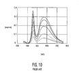
- FIG. 10 A typical power radiation spectrum of a white-light phosphor converted LED package under different DC driving currents is shown in FIG. 10 .
- the first spectral hump at around460nm is due to the emission from the LED junction (InGaN) and the second hump with broader bandwidth with a peak around 500-600nm is due to the emission from the yellow phosphor pumped by photons at around 46nm.
- JP 2001 144332 discloses a modulation of an amplitude of a LED drive current of a phosphor converted LED to change a color of light emitted by the LED.
- US-B1-6 411 046 discloses driving an array of LEDs comprising LEDs having different colors, the array being coupled to mixing optics. Light output and color are measured for different temperatures and the LED's are driven accordingly.
- the present invention is directed to a method according to claim 1 to provide color correction in emission spectra of a phosphor converted LED (PC-LED) under pulse-width-modulation (PWM) current drive.
- a modulation for a driving current signal is determined.
- a constant magnitude current signal is modulated based on the determined modulation.
- the modulated current signal is applied to cause a color temperature correction in the emission spectra of the LED.
- an apparatus to provide color temperature correction in an emission spectra of a phosphor converted LED is provided.
- the apparatus includes a color correction control circuit and a phosphor converted LED coupled to the control circuit.
- FIG. 1 shows a typical driving current/blue light emission 100 and the corresponding phosphor light output 110 at a low frequency f 1 and T off >> 4 T p .
- a pc-white LED is driven under square wave current with constant amplitude and frequency f 0 .
- the blue light emission from the LED junction generally follows the driving current signal when f 0 ⁇ 10 MHz assuming that the LED response time is under 50ns. For the present example assume f 1 ⁇ 200 Hz.
- a color coordinate pair referencing a CIE color chart may be determined that describes the combined emissions of the LED junction and the phosphor.
- FIGS. 2 and 3 show typical LED driving current/blue light emissions and the corresponding phosphor light outputs 210, 310 respectively at mid-range frequency f mid , such as f 2 200 with T off > 4 T p , and f 3 300 with T o ff ⁇ 4 T p .
- f mid mid-range frequency
- the phosphor light decay process starts to have an effect on the LED white-light color point.
- the white-light color points ( x w , y w ) may then be determined based on equations (2), (3) and (5).
- FIG. 4 shows a typical LED driving current/blue light emission 400 and the corresponding phosphor light output 410 at a higher frequency f 4 with T off ⁇ 4 T p .
- the phosphor light decay process has a substantial effect on the LED white-light color point. While the blue light intensity is still maintained as L b T on f 0 , the yellow light intensity becomes the linear combination of a prior shift such as discussed in FIGS. 2 and 3 and a further increase due to the higher frequency drive signal.
- the white-light color coordinate points ( x w ,y w ) may again be determined based on equation (2), (3) and (6).
- the duty cycle may be alternatively used to modulate a CCT color shift with a corresponding increase in the total light output of the LED.
- both duty cycle and frequency modulation to the constant magnitude PWM current signal to maintain a constant light output while compensating for a color temperature shift.
- Coupled means either a direct electrical connection between the things that are described or a connection through one or more passive or active components.
- color coordinates means "white-light color coordinates.”
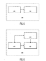
- FIG. 5 is a block diagram of a color corrected phosphor-converted LED system in an embodiment of the invention.
- FIG. 5 shows a color corrected PC-LED system 500 comprising a color correction control circuit 600, and a phosphor-converted LED 520.
- the color correction control circuit 600 (hereinafter, control circuit) is shown coupled to the phosphor-converted LED 520 (hereinafter, PC-LED.)
- PC-LED phosphor-converted LED
- the control circuit 600 is a generally a combination of systems and devices that provides color correction control to the PC-LED 520.
- the control circuit 600 is arranged when operational to determine a modulation for a driving current signal, modulate a constant magnitude current signal based on the determined modulation, and then apply the modulated current signal to the PC-LED 520 to cause a color correction in the output emission spectra of the PC-LED 520.
- the PC-LED 520 is any phosphor-converted LED suitable for color correction.
- the PC-LED 520 generally has an operational temperature induced CCT shift.
- the invention may be applied to a PC-LED 520 for color conversion when any CCT shift is desired, whether the shift is to reverse an operational temperature-induced CCT shift or not.
- a low-cost white-light PC-LED 520 may have an undesirable color coordinate set for a particular application such as reading illumination or nightlights, and therefore a color adjustment to the LED output may be accomplished using the control circuit 600 to either shift the CCT up or down depending on the application.
- the invention may be applied to any PC-LED, including PC-LEDs that are designed to have spectral output other than white light.
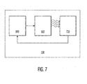
- FIG. 6 is a block diagram of a color correction control circuit in an embodiment of the invention.
- FIG. 6 shows a color correction control circuit 600 comprising a power supply 650, a PWM modulator 660, and a processor control system 670.
- the power supply 650 is shown coupled to the processor control system 670 and the PWM modulator 660.
- the processor control system 670 is also shown coupled to the PWM modulator 660. Additional components (not shown) may be included in the control circuit 600 such as voltage and current regulation components, temperature monitoring apparatus, user controls and the like.
- the power supply 650 selectively couples regulated or unregulated power to a load, and may include various regulation circuits.
- the power supply 650 is selectively coupled to the PWM modulator 660 based on control signals from the processor control system 670.
- control signals from the processor control system 670 Various means and methods for generating and controlling a pulse-width modulated current signal and coupling the signal to a load will be known to those skilled in the art, and will not be elaborated.
- the processor control system 670 is a control system generally comprised of a processor such as a microcontroller (not shown) and various connected components such as, for example, input/output interfaces, memory (not shown) containing stored processor-executable instructions (not shown) and stored data (not shown).
- the processor control system may have a memory containing predetermined reference data such as, for example, color coordinate points determined according to equation (1) referenced to an LED operational temperature curve.
- the processor control system 670 is configured to receive LED operational temperature information to allow LED temperature-based color correction based on a lookup table of calculated color coordinates.
- the processor control system 670 is configured to determine a modulation scheme to cause a CCT shift in the output spectrum of an LED such as PC-LED 520.
- the processor control system 670 is enabled to determine a frequency and/or duty-cycle modulation to a PWM driving current signal.
- the processor control system 670 may collect measured data in real-time based on the output of an LED, such as is depicted in FIG. 7 .
- the processor control system 670 determines a modulation through a calculation of color coordinate pairs according to equation (1) based on various data such as PC-LED 520 output intensity.
- Various configurations to implement a processor control system 670 will be known to those skilled in the art, and will not be elaborated.
- circuit embodiments for implementing the invention are possible, such as the simplified circuit embodiment for applying a modulation to an LED string as shown in FIG. 9 .
- FIG. 7 is a block diagram of a color corrected phosphor-converted LED system with color sensing in another embodiment of the invention.
- FIG. 7 shows a color corrected PC-LED system 700, comprising a color correction control circuit 600, a phosphor-converted LED 520 and a color sensing system 730.
- the color correction control circuit 600 is shown coupled to the phosphor-converted LED 520.
- the phosphor-converted LED 520 is shown radiating light to the color sensing system 730.
- the color corrected system 700 comprises the same elements as the color corrected system 500 of FIG. 5 with the addition of the color sensing system 730.
- the color sensing system is any system designed to sense color in response to a light source such as PC-LED 520.
- the color sensing system 730 is configured to sense the CCT of the PC-LED 520 light emissions and to provide a color signal to the color correction circuit based on the sensed light emissions.
- the color sensing system may send the color signal in any form such as a digitally modulated or analog signal representing the spectral content of the PC-LED 520 light emissions.
- a feedback control loop between the color sensing system 730 and the control circuit 600 is then capable to control the CCT of the PC-LED 520 emission spectra over time and under variable parameters.
- Various other configurations to implement a color sensing system 730 in the color corrected system 700 will be known to those skilled in the art, and will not be elaborated.
- FIG. 8 shows a process for providing color correction in emission spectra of a phosphor converted LED under PWM current drive.
- Process 800 begins in step 810.
- a modulation is determined for a driving current signal.
- the modulation is generally a frequency or duty ratio modulation to be applied to a square wave PWM current signal.
- the modulation is determined at any time. For instance, the modulation may be determined in response to a data signal, a turn-on cycle or user input.
- the determination is generally performed by a system such as a color correction control circuit as in FIGS. 5, 6 and 7 .
- the modulation determination may be predetermined based on a manufacturer data according to equation (1), and provided in a lookup table for reference by a processor, such as processor control system 670.
- a modulation determination is made based on criteria such as a desired CCT of a PC-LED under varying operational conditions such as temperature, total light output, and phosphor composition.
- a modulation may be determined by simultaneously solving equations (2), (3), (4), or (5) with equation (1) where a coordinate pair ( x w , y w ) is pre-selected.
- a constant-magnitude current signal is modulated based on the modulation determined in step 810.
- the constant magnitude current signal is generally provided by a regulated power supply, such as power supply 650.
- a processor control system 670 selectively couples power to a PWM modulator 660 from a power supply 650 to generate a modulated current signal based on the modulation determined in step 810.
- Other methods for modulating a constant magnitude PWM current signal with a current and/or frequency modulation will be apparent to those skilled the art and will not be further elaborated.
- the modulated current signal is applied to cause a color correction in the emission spectra of a PC-LED.
- the modulated current signal is applied to an LED such as the PC-LED 520.
- the current signal modulated in step 820 is delivered from a color correction circuit 600 to the PC-LED 520.
- the modulated current signal is applied at any time after the current signal is modulated in step 820. Applying the modulated current signal to PC-LED 520 accomplishes a correction to a CCT shift due to temperature induces drift, or for another purpose.
- the applied current signal includes both a frequency and a duty ratio modulation to allow CCT correction without affecting the total light output of the PC-LED to which the current signal is applied.
Abstract
Description
- The invention relates to methods operating light emitting diodes. More particularly the invention relates to techniques for color correction of light emitting diode emission spectra.
- In the existing market, white LED lamps can be obtained from Nichia, LumiLeds and other opto-semiconductor manufactures. A single-chip white-light LED has great potential for the illumination market. White-light LEDs do not need complex control and driving circuits or color mixing optics and have an almost unified fabrication processes. The existing vehicles for single chip based LED white light generation are based on wavelength conversion technology using different types of fluorescent and phosphorescent materials. In principle, Blue or UV wavelength emission from the LED junction is used to pump a coated phosphor for spectral down-conversion. One example is the LumiLeds white LED with yellow phosphor.
- Persistence of phosphors is generally characterized by approximately an exponential decay of the form e-at, or of the power law t-n, or combinations of the two forms. In this discussion, without loss of generality, the phosphor light decay process is approximated using an equation of the form:

where Ly is the initial phosphor light emission at the moment that blue or UV excitation is removed. - The phosphorescence time with persistence to the 10% level (denoted as decay time Tpd ) varies from less than 1 µs to more than 1 second depending on the characteristics of the material used. In the existing high power PC-LED samples, the measured decay time constant (Tp ) is less than 1 µs. Note that Tpd ≈4Tp. It is common for phosphors exhibiting rapid rise and decay characteristics to have approximately 50% less brightness efficiency compared to the conventional medium level P20 yellow/green phosphor which usually have 10 µs to 100 ms of decay persistence time. From a data table of available PC-LEDs, it is observed that the phosphor rise time Tpr is usually a few times less than the decay time. The phosphor in a pc-white LED is ideally designed with persistence time in the range of approximately 100 µs to 10 ms.
- A typical power radiation spectrum of a white-light phosphor converted LED package under different DC driving currents is shown in
FIG. 10 . The first spectral hump at around460nm is due to the emission from the LED junction (InGaN) and the second hump with broader bandwidth with a peak around 500-600nm is due to the emission from the yellow phosphor pumped by photons at around 46nm. - Once the phosphor material is coated around the die dome during the manufacturing process, the relative emission spectra of a pc-white LED is fixed. Under normal DC current driving condition, the resulting white-light correlated color temperature (CCT) and color rendering index (CRI) are almost fixed at a particular junction operational temperature, say 25C. When the junction temperature changes from 25C to 80C, experimental results show that almost 800K CCT increase could result. The CCT shift is recognized as an unfortunate and undesirable property of phosphor-converted white LEDs. An LED CCT shift has a corresponding shifting effect on human color perception of objects illuminated by the LED.
- Additionally, existing methods for altering the spectral content of multi-color LEDs emission require a resort to multiple variable-magnitude current sources, which results in increased complexity and cost. It would therefore be desirable to provide a method of utilizing existing pc-white LEDs to overcome these and other limitations.
-
JP 2001 144332 US-B1-6 411 046 discloses driving an array of LEDs comprising LEDs having different colors, the array being coupled to mixing optics. Light output and color are measured for different temperatures and the LED's are driven accordingly. - The present invention is directed to a method according to claim 1 to provide color correction in emission spectra of a phosphor converted LED (PC-LED) under pulse-width-modulation (PWM) current drive. A modulation for a driving current signal is determined. A constant magnitude current signal is modulated based on the determined modulation. The modulated current signal is applied to cause a color temperature correction in the emission spectra of the LED.
- In accordance with another aspect of the invention an apparatus according to claim 12 to provide color temperature correction in an emission spectra of a phosphor converted LED is provided. The apparatus includes a color correction control circuit and a phosphor converted LED coupled to the control circuit.
- The foregoing and other features and advantages of the invention are apparent from the following detailed description of exemplary embodiments, read in conjunction with the accompanying drawings. The detailed description and drawings are merely illustrative of the invention rather than limiting, the scope of the invention being defined by the appended claims and equivalents thereof.
-
FIG. 1 shows a typical PC-LED drivingcurrent/blue light emission and the corresponding phosphor light output at a lowfrequency f1 and Toff >> 4 Tp -
FIG. 2 shows typical PC-LED driving current/blue light emission and the corresponding phosphor light output at a mid-rangefrequency f2 with Toff - > 4 Tp. -
FIG. 3 shows a typical PC-LED driving current/blue light emission and the corresponding phosphor light output at a mid-rangefrequency f3 with T off ~ 4 Tp. -
FIG. 4 shows a typical LED drivingcurrent/blue light emission and the corresponding phosphor light output at a mid-rangefrequency f2 with Toff < 4 Tp. -
FIG. 5 is a block diagram of a color corrected phosphor-converted LED system in an embodiment of the invention. -
FIG. 6 is a block diagram of a color correction control circuit in an embodiment of the invention. -
FIG. 7 is a block diagram of a color corrected phosphor-converted LED system with color sensing in another embodiment of the invention. -
FIG. 8 shows a process for providing color correction in emission spectra of a phosphor converted LED under PWM current drive. -
FIG. 9 shows a prior art simplified circuit embodiment for applying a modulation to a LED string. -
FIG. 10 shows a prior art power radiation spectrum of a white light phosphor-converted LED. -
FIG. 1 shows a typical driving current/blue light emission 100 and the correspondingphosphor light output 110 at a low frequency f1 and Toff >> 4 Tp. Generally, a pc-white LED is driven under square wave current with constant amplitude and frequency f0 . The duty ratio of the drive signal is D = Ton /(Toff + Ton)= Ton /T = Tonf0. Correspondingly, the blue light emission from the LED junction generally follows the driving current signal when f0 < 10 MHz assuming that the LED response time is under 50ns. For the present example assume f1 ≈200 Hz. Under this condition, the phosphor rise and decay time are so small compared with the off time Toff that they can be neglected. A color coordinate pair referencing a CIE color chart may be determined that describes the combined emissions of the LED junction and the phosphor. The white-light color point coordinates (xw ,yw ) are determined by an equation of the form:
where (xb,yb) and (xy,yy) are the color coordinates of the blue light and yellow phosphor light respectively, with intensities:

-
FIGS. 2 and3 show typical LED driving current/blue light emissions and the correspondingphosphor light outputs f 2 200 with Toff > 4 Tp, andf 3 300 with T off ~4 Tp. In the middle frequency range, the phosphor light decay process starts to have an effect on the LED white-light color point. While the blue light intensity is maintained as LbTonf0, and the yellow light intensity is represented by the equation in the form:
with α> 1. - The white-light color points (xw ,yw ) may then be determined based on equations (2), (3) and (5).
-
FIG. 4 shows a typical LED driving current/blue light emission 400 and the correspondingphosphor light output 410 at a higher frequency f4 with Toff < 4 Tp. In the higher frequency range, the phosphor light decay process has a substantial effect on the LED white-light color point. While the blue light intensity is still maintained as LbTonf0, the yellow light intensity becomes the linear combination of a prior shift such as discussed inFIGS. 2 and3 and a further increase due to the higher frequency drive signal. The yellow light intensity is then represented by the equation in the form:
with α > 1. - The white-light color coordinate points (xw,yw ) may again be determined based on equation (2), (3) and (6). Note that since the PWM driving current duty ratio is independent of the driving current frequency, the duty cycle may be alternatively used to modulate a CCT color shift with a corresponding increase in the total light output of the LED. Furthermore it is possible to employ both duty cycle and frequency modulation to the constant magnitude PWM current signal to maintain a constant light output while compensating for a color temperature shift. In the described manner, it is possible to modulate the magnitude and shape of the emission spectra of a phosphor converted LED using a modulated PWM current signal.
- In the following descriptions, the term "coupled" means either a direct electrical connection between the things that are described or a connection through one or more passive or active components. The phrase "color coordinates" means "white-light color coordinates."
-
FIG. 5 is a block diagram of a color corrected phosphor-converted LED system in an embodiment of the invention.FIG. 5 shows a color corrected PC-LED system 500 comprising a colorcorrection control circuit 600, and a phosphor-convertedLED 520. InFIG. 5 , the color correction control circuit 600 (hereinafter, control circuit) is shown coupled to the phosphor-converted LED 520 (hereinafter, PC-LED.) An embodiment of thecontrol circuit 600 will later be described in detail in reference toFIG. 6 . - The
control circuit 600 is a generally a combination of systems and devices that provides color correction control to the PC-LED 520. Thecontrol circuit 600 is arranged when operational to determine a modulation for a driving current signal, modulate a constant magnitude current signal based on the determined modulation, and then apply the modulated current signal to the PC-LED 520 to cause a color correction in the output emission spectra of the PC-LED 520. - The PC-
LED 520 is any phosphor-converted LED suitable for color correction. In particular, the PC-LED 520 generally has an operational temperature induced CCT shift. However, the invention may be applied to a PC-LED 520 for color conversion when any CCT shift is desired, whether the shift is to reverse an operational temperature-induced CCT shift or not. For example, a low-cost white-light PC-LED 520 may have an undesirable color coordinate set for a particular application such as reading illumination or nightlights, and therefore a color adjustment to the LED output may be accomplished using thecontrol circuit 600 to either shift the CCT up or down depending on the application. It should be noted that while the present discussion applies to phosphor converted white-light LEDs, the invention may be applied to any PC-LED, including PC-LEDs that are designed to have spectral output other than white light. -
FIG. 6 is a block diagram of a color correction control circuit in an embodiment of the invention.FIG. 6 shows a colorcorrection control circuit 600 comprising apower supply 650, aPWM modulator 660, and aprocessor control system 670. Thepower supply 650 is shown coupled to theprocessor control system 670 and thePWM modulator 660. Theprocessor control system 670 is also shown coupled to thePWM modulator 660. Additional components (not shown) may be included in thecontrol circuit 600 such as voltage and current regulation components, temperature monitoring apparatus, user controls and the like. Thepower supply 650 selectively couples regulated or unregulated power to a load, and may include various regulation circuits. - In operation, the
power supply 650 is selectively coupled to thePWM modulator 660 based on control signals from theprocessor control system 670. Various means and methods for generating and controlling a pulse-width modulated current signal and coupling the signal to a load will be known to those skilled in the art, and will not be elaborated. - The
processor control system 670 is a control system generally comprised of a processor such as a microcontroller (not shown) and various connected components such as, for example, input/output interfaces, memory (not shown) containing stored processor-executable instructions (not shown) and stored data (not shown). The processor control system may have a memory containing predetermined reference data such as, for example, color coordinate points determined according to equation (1) referenced to an LED operational temperature curve. In one embodiment (not shown), theprocessor control system 670 is configured to receive LED operational temperature information to allow LED temperature-based color correction based on a lookup table of calculated color coordinates. - In operation, the
processor control system 670 is configured to determine a modulation scheme to cause a CCT shift in the output spectrum of an LED such as PC-LED 520. Theprocessor control system 670 is enabled to determine a frequency and/or duty-cycle modulation to a PWM driving current signal. In one embodiment, theprocessor control system 670 may collect measured data in real-time based on the output of an LED, such as is depicted inFIG. 7 . In one embodiment, theprocessor control system 670 determines a modulation through a calculation of color coordinate pairs according to equation (1) based on various data such as PC-LED 520 output intensity. Various configurations to implement aprocessor control system 670 will be known to those skilled in the art, and will not be elaborated. - A skilled practitioner will recognize that other circuit embodiments for implementing the invention are possible, such as the simplified circuit embodiment for applying a modulation to an LED string as shown in
FIG. 9 . -
FIG. 7 is a block diagram of a color corrected phosphor-converted LED system with color sensing in another embodiment of the invention.FIG. 7 shows a color corrected PC-LED system 700, comprising a colorcorrection control circuit 600, a phosphor-convertedLED 520 and acolor sensing system 730. InFIG. 7 , the colorcorrection control circuit 600 is shown coupled to the phosphor-convertedLED 520. The phosphor-convertedLED 520 is shown radiating light to thecolor sensing system 730. - The color corrected
system 700 comprises the same elements as the color correctedsystem 500 ofFIG. 5 with the addition of thecolor sensing system 730. The color sensing system is any system designed to sense color in response to a light source such as PC-LED 520. - In operation, the
color sensing system 730 is configured to sense the CCT of the PC-LED 520 light emissions and to provide a color signal to the color correction circuit based on the sensed light emissions. The color sensing system may send the color signal in any form such as a digitally modulated or analog signal representing the spectral content of the PC-LED 520 light emissions. A feedback control loop between thecolor sensing system 730 and thecontrol circuit 600 is then capable to control the CCT of the PC-LED 520 emission spectra over time and under variable parameters. Various other configurations to implement acolor sensing system 730 in the color correctedsystem 700 will be known to those skilled in the art, and will not be elaborated. - In the following process description one or more steps may be combined or performed simultaneously without departing from the invention.
-
FIG. 8 shows a process for providing color correction in emission spectra of a phosphor converted LED under PWM current drive.Process 800 begins instep 810. Instep 810, a modulation is determined for a driving current signal. The modulation is generally a frequency or duty ratio modulation to be applied to a square wave PWM current signal. The modulation is determined at any time. For instance, the modulation may be determined in response to a data signal, a turn-on cycle or user input. The determination is generally performed by a system such as a color correction control circuit as inFIGS. 5, 6 and7 . Alternatively, the modulation determination may be predetermined based on a manufacturer data according to equation (1), and provided in a lookup table for reference by a processor, such asprocessor control system 670. A modulation determination is made based on criteria such as a desired CCT of a PC-LED under varying operational conditions such as temperature, total light output, and phosphor composition. A modulation may be determined by simultaneously solving equations (2), (3), (4), or (5) with equation (1) where a coordinate pair (xw ,yw ) is pre-selected. - In
step 820, a constant-magnitude current signal is modulated based on the modulation determined instep 810. The constant magnitude current signal is generally provided by a regulated power supply, such aspower supply 650. In one embodiment, aprocessor control system 670 selectively couples power to aPWM modulator 660 from apower supply 650 to generate a modulated current signal based on the modulation determined instep 810. Other methods for modulating a constant magnitude PWM current signal with a current and/or frequency modulation will be apparent to those skilled the art and will not be further elaborated. - In
step 830, the modulated current signal is applied to cause a color correction in the emission spectra of a PC-LED. The modulated current signal is applied to an LED such as the PC-LED 520. In one embodiment, the current signal modulated instep 820 is delivered from acolor correction circuit 600 to the PC-LED 520. The modulated current signal is applied at any time after the current signal is modulated instep 820. Applying the modulated current signal to PC-LED 520 accomplishes a correction to a CCT shift due to temperature induces drift, or for another purpose. In one embodiment, the applied current signal includes both a frequency and a duty ratio modulation to allow CCT correction without affecting the total light output of the PC-LED to which the current signal is applied. - While the preferred embodiments of the invention have been shown and described, numerous variations and alternative embodiments will occur to those skilled in the art. Accordingly, it is intended that the invention be limited only in terms of the appended claims.
Claims (20)
- A method to provide color temperature correction in emission spectra of a phosphor converted LED under PWM current drive comprising:- determining a modulation for a driving current signal (810) ;- modulating a constant magnitude current signal based on the determined modulation (820); and- applying the modulated current signal to cause a color temperature correction in the emission spectra (830) of the LED, the modulation comprising using a frequency and/or a duty cycle modulation of the driving current signal for setting an off-time of the driving current signal relative to the phosphor decay constant, for having a phosphor decay process influence a LED white-light color point.
- The method according to claim 1, wherein the off-time is set to be equal to or to be smaller than 4 times the phosphor decay constant.
- The method of claim 1 wherein determining a modulation (810) includes determining a first LED (520) emission spectra color coordinate set and a second LED (520) emission spectra color coordinate set wherein the first color coordinate set represents LED (520) emission spectra at a first LED (520) operational temperature and the second color coordinate set represents a correlated color temperature shift in the LED (520) emission spectra due to operation of the LED (520) at a second operational temperature.
- The method of claim 3 wherein the current signal modulation is determined(810) such that applying the determined current signal modulation(830) to the LED (520) causes the LED (520) emission spectra at the first color coordinate set to reverse an operational temperature induced correlated color temperature shift as the LED (520) operational temperature changes from the first LED (520) operational temperature to the second LED (520) operational temperature.
- The method claim 1 wherein the modulation includes changing the current signal frequency.
- The method of claim 1 wherein the modulation includes changing the current signal duty-cycle.
- The method of claim 6 wherein the total light output of the LED (520) is changed responsive to the changing of the current signal duty cycle.
- The method of claim 6 wherein the current signal frequency is changed to maintain a constant total light output of the LED (520).
- The method of claim 1 wherein applying the modulated current signal (830) includes selectively coupling a power supply 650 to a phosphor converted LED (520) based on the determined modulation.
- The method of claim 9 wherein the LED (520) is a phosphor converted white light LED.
- The method of claim 10 wherein the LED (520) junction emission intensity is substantially constant while the phosphor emission intensity is increased responsive to the current signal modulation.
- An apparatus to provide color temperature correction in an emission spectra of a phosphor converted LED (520) comprising:- a color correction control circuit (600); and- a phosphor converted LED (520) coupled to the control circuit (600)wherein the control circuit is configured to determine a modulation(810) for an LED (520) driving current signal modulate a constant magnitude current signal based on the determined modulation (820) and apply the modulated current signal (830) to the LED (520) to cause a color temperature correction in the emission spectra of the LED (520), the modulation comprising using a frequency and/or a duty cycle modulation of the driving current signal for setting an off-time of the driving current signal relative to the phosphor decay constant, for having a phosphor decay process influence a LED white-light color point.
- The apparatus according to claim 12, wherein the control circuit is configured to set the off-time to be equal to or smaller than 4 times the phosphor decay constant.
- The apparatus of claim 12 wherein the control circuit (600) includes a constant-current magnitude pulse width modulator circuit 660 having configurable frequency and duty cycle.
- The apparatus of claim 14 wherein the control circuit (600) includes a power supply (650) selectively arranged to deliver power to the pulse width modulator circuit (660).
- The apparatus of claim 12 wherein the control circuit (600) includes a processor control system 670.
- The apparatus of claim 16 wherein the processor control system (670) is enabled to control the steps of :- determining a modulation for an LED (520) driving current signal (810);- modulating a constant magnitude current signal based on the determined modulation (820); and- applying the modulated current signal (830) to the LED (520) to cause a color temperature correction in the emission spectra of the LED (520).
- The apparatus of claim 17 wherein determining a modulation(810) includes- determining a first LED (520) emission spectra color coordinate set and a second LED (520) emission spectra color coordinate set wherein the first color coordinate set represents LED (520) emission spectra at a first LED (520) operational temperature and the second color coordinate set represents a correlated color temperature shift in the LED (520) emission spectra due to operation of the LED (520) at a second operational temperature andwherein a current signal modulation is determined (810) such that applying the determined current signal modulation (830) to the LED (520) causes the LED (520) emission spectra at the first color coordinate set to reverse an operational temperature induced correlated color temperature shift as the LED (520) operational temperature changes from the first LED (520) operational temperature to the second LED (520) operational temperature.
- The apparatus of claim 12 wherein the LED (520) is a white light phosphor converted LED.
- The apparatus of claim 17 wherein the LED (520) is an InGaN phosphor converted white-light LED (520).
Applications Claiming Priority (3)
| Application Number | Priority Date | Filing Date | Title |
|---|---|---|---|
| US43685902P | 2002-12-26 | 2002-12-26 | |
| US436859P | 2002-12-26 | ||
| PCT/IB2003/006099 WO2004060024A1 (en) | 2002-12-26 | 2003-12-18 | Color temperature correction for phosphor converted leds |
Publications (2)
| Publication Number | Publication Date |
|---|---|
| EP1579733A1 EP1579733A1 (en) | 2005-09-28 |
| EP1579733B1 true EP1579733B1 (en) | 2008-04-09 |
Family
ID=32682415
Family Applications (1)
| Application Number | Title | Priority Date | Filing Date |
|---|---|---|---|
| EP03777121A Expired - Lifetime EP1579733B1 (en) | 2002-12-26 | 2003-12-18 | Color temperature correction for phosphor converted leds |
Country Status (10)
| Country | Link |
|---|---|
| US (1) | US20060114201A1 (en) |
| EP (1) | EP1579733B1 (en) |
| JP (1) | JP2006512759A (en) |
| KR (2) | KR101223943B1 (en) |
| CN (1) | CN100493280C (en) |
| AT (1) | ATE392122T1 (en) |
| AU (1) | AU2003286376A1 (en) |
| DE (1) | DE60320307T2 (en) |
| TW (1) | TW200423021A (en) |
| WO (1) | WO2004060024A1 (en) |
Cited By (35)
| Publication number | Priority date | Publication date | Assignee | Title |
|---|---|---|---|---|
| US7938562B2 (en) | 2008-10-24 | 2011-05-10 | Altair Engineering, Inc. | Lighting including integral communication apparatus |
| US7946729B2 (en) | 2008-07-31 | 2011-05-24 | Altair Engineering, Inc. | Fluorescent tube replacement having longitudinally oriented LEDs |
| US7976196B2 (en) | 2008-07-09 | 2011-07-12 | Altair Engineering, Inc. | Method of forming LED-based light and resulting LED-based light |
| US8214084B2 (en) | 2008-10-24 | 2012-07-03 | Ilumisys, Inc. | Integration of LED lighting with building controls |
| US8256924B2 (en) | 2008-09-15 | 2012-09-04 | Ilumisys, Inc. | LED-based light having rapidly oscillating LEDs |
| US8299695B2 (en) | 2009-06-02 | 2012-10-30 | Ilumisys, Inc. | Screw-in LED bulb comprising a base having outwardly projecting nodes |
| US8324817B2 (en) | 2008-10-24 | 2012-12-04 | Ilumisys, Inc. | Light and light sensor |
| US8330381B2 (en) | 2009-05-14 | 2012-12-11 | Ilumisys, Inc. | Electronic circuit for DC conversion of fluorescent lighting ballast |
| US8360599B2 (en) | 2008-05-23 | 2013-01-29 | Ilumisys, Inc. | Electric shock resistant L.E.D. based light |
| US8362710B2 (en) | 2009-01-21 | 2013-01-29 | Ilumisys, Inc. | Direct AC-to-DC converter for passive component minimization and universal operation of LED arrays |
| US8421366B2 (en) | 2009-06-23 | 2013-04-16 | Ilumisys, Inc. | Illumination device including LEDs and a switching power control system |
| US8444292B2 (en) | 2008-10-24 | 2013-05-21 | Ilumisys, Inc. | End cap substitute for LED-based tube replacement light |
| US8454193B2 (en) | 2010-07-08 | 2013-06-04 | Ilumisys, Inc. | Independent modules for LED fluorescent light tube replacement |
| US8523394B2 (en) | 2010-10-29 | 2013-09-03 | Ilumisys, Inc. | Mechanisms for reducing risk of shock during installation of light tube |
| US8541958B2 (en) | 2010-03-26 | 2013-09-24 | Ilumisys, Inc. | LED light with thermoelectric generator |
| US8540401B2 (en) | 2010-03-26 | 2013-09-24 | Ilumisys, Inc. | LED bulb with internal heat dissipating structures |
| US8556452B2 (en) | 2009-01-15 | 2013-10-15 | Ilumisys, Inc. | LED lens |
| US8596813B2 (en) | 2010-07-12 | 2013-12-03 | Ilumisys, Inc. | Circuit board mount for LED light tube |
| US8653984B2 (en) | 2008-10-24 | 2014-02-18 | Ilumisys, Inc. | Integration of LED lighting control with emergency notification systems |
| US8664880B2 (en) | 2009-01-21 | 2014-03-04 | Ilumisys, Inc. | Ballast/line detection circuit for fluorescent replacement lamps |
| US8674626B2 (en) | 2008-09-02 | 2014-03-18 | Ilumisys, Inc. | LED lamp failure alerting system |
| US8870415B2 (en) | 2010-12-09 | 2014-10-28 | Ilumisys, Inc. | LED fluorescent tube replacement light with reduced shock hazard |
| US8901823B2 (en) | 2008-10-24 | 2014-12-02 | Ilumisys, Inc. | Light and light sensor |
| US8928025B2 (en) | 2007-12-20 | 2015-01-06 | Ilumisys, Inc. | LED lighting apparatus with swivel connection |
| US9057493B2 (en) | 2010-03-26 | 2015-06-16 | Ilumisys, Inc. | LED light tube with dual sided light distribution |
| US9072171B2 (en) | 2011-08-24 | 2015-06-30 | Ilumisys, Inc. | Circuit board mount for LED light |
| US9163794B2 (en) | 2012-07-06 | 2015-10-20 | Ilumisys, Inc. | Power supply assembly for LED-based light tube |
| US9184518B2 (en) | 2012-03-02 | 2015-11-10 | Ilumisys, Inc. | Electrical connector header for an LED-based light |
| US9222629B2 (en) | 2010-12-17 | 2015-12-29 | Dolby Laboratories Licensing Corporation | N-modulation for wide color gamut and high brightness |
| US9271367B2 (en) | 2012-07-09 | 2016-02-23 | Ilumisys, Inc. | System and method for controlling operation of an LED-based light |
| US9267650B2 (en) | 2013-10-09 | 2016-02-23 | Ilumisys, Inc. | Lens for an LED-based light |
| US9285084B2 (en) | 2013-03-14 | 2016-03-15 | Ilumisys, Inc. | Diffusers for LED-based lights |
| US9510400B2 (en) | 2014-05-13 | 2016-11-29 | Ilumisys, Inc. | User input systems for an LED-based light |
| US9574717B2 (en) | 2014-01-22 | 2017-02-21 | Ilumisys, Inc. | LED-based light with addressed LEDs |
| US10161568B2 (en) | 2015-06-01 | 2018-12-25 | Ilumisys, Inc. | LED-based light with canted outer walls |
Families Citing this family (55)
| Publication number | Priority date | Publication date | Assignee | Title |
|---|---|---|---|---|
| FI115600B (en) | 2003-06-27 | 2005-05-31 | Planmeca Oy | LED surgical lighting apparatus |
| US7318651B2 (en) | 2003-12-18 | 2008-01-15 | Avago Technologies Ecbu Ip (Singapore) Pte. Ltd. | Flash module with quantum dot light conversion |
| US7667766B2 (en) | 2003-12-18 | 2010-02-23 | Avago Technologies Ecbu Ip (Singapore) Pte. Ltd. | Adjustable spectrum flash lighting for image acquisition |
| US20050259424A1 (en) | 2004-05-18 | 2005-11-24 | Zampini Thomas L Ii | Collimating and controlling light produced by light emitting diodes |
| ATE498206T1 (en) * | 2004-11-18 | 2011-02-15 | Koninkl Philips Electronics Nv | LIGHT SOURCE WITH IMPROVED DARKING BEHAVIOR AND METHOD FOR CONTROLLING IT |
| US7522211B2 (en) | 2005-02-10 | 2009-04-21 | Avago Technologies Ecbu Ip (Singapore) Pte. Ltd. | Studio light |
| TW200704283A (en) * | 2005-05-27 | 2007-01-16 | Lamina Ceramics Inc | Solid state LED bridge rectifier light engine |
| WO2006131847A1 (en) * | 2005-06-07 | 2006-12-14 | Koninklijke Philips Electronics N.V. | Illumination system |
| JP5419452B2 (en) * | 2005-08-15 | 2014-02-19 | コーニンクレッカ フィリップス エヌ ヴェ | Light source and method for generating light of variable color and / or brightness |
| EP1955577A1 (en) * | 2005-11-22 | 2008-08-13 | Koninklijke Philips Electronics N.V. | Led lighting system and control method |
| US7994530B2 (en) | 2006-03-06 | 2011-08-09 | Koninklijke Philips Electronics N.V. | Light emitting diode module |
| US7766511B2 (en) | 2006-04-24 | 2010-08-03 | Integrated Illumination Systems | LED light fixture |
| US7729941B2 (en) | 2006-11-17 | 2010-06-01 | Integrated Illumination Systems, Inc. | Apparatus and method of using lighting systems to enhance brand recognition |
| US8013538B2 (en) | 2007-01-26 | 2011-09-06 | Integrated Illumination Systems, Inc. | TRI-light |
| US8410727B2 (en) | 2007-03-08 | 2013-04-02 | Rohm Co., Ltd. | LED lighting device and driving method for the same |
| US8203260B2 (en) * | 2007-04-13 | 2012-06-19 | Intematix Corporation | Color temperature tunable white light source |
| US20080252609A1 (en) * | 2007-04-16 | 2008-10-16 | Yan-Zhi Lu | Image display and touch input integration module |
| US7703943B2 (en) * | 2007-05-07 | 2010-04-27 | Intematix Corporation | Color tunable light source |
| DE102007022794B4 (en) * | 2007-05-11 | 2015-12-31 | Ulrich Theodor Schwarz | Method for operating a light-emitting diode and Lumineszenzdiodenanorndung |
| US8742686B2 (en) | 2007-09-24 | 2014-06-03 | Integrated Illumination Systems, Inc. | Systems and methods for providing an OEM level networked lighting system |
| TWI371630B (en) * | 2007-12-06 | 2012-09-01 | Au Optronics Corp | Backlight module and method of manufacture using complementary light sources having the same color |
| WO2009095817A1 (en) * | 2008-01-31 | 2009-08-06 | Koninklijke Philips Electronics N.V. | Lighting unit and thermal management system and method therefor |
| US8255487B2 (en) | 2008-05-16 | 2012-08-28 | Integrated Illumination Systems, Inc. | Systems and methods for communicating in a lighting network |
| KR20100030470A (en) * | 2008-09-10 | 2010-03-18 | 삼성전자주식회사 | Light emitting device and system providing white light with various color temperatures |
| US8022631B2 (en) * | 2008-11-03 | 2011-09-20 | General Electric Company | Color control of light sources employing phosphors |
| US20100214282A1 (en) | 2009-02-24 | 2010-08-26 | Dolby Laboratories Licensing Corporation | Apparatus for providing light source modulation in dual modulator displays |
| US8585245B2 (en) | 2009-04-23 | 2013-11-19 | Integrated Illumination Systems, Inc. | Systems and methods for sealing a lighting fixture |
| US9066381B2 (en) | 2011-03-16 | 2015-06-23 | Integrated Illumination Systems, Inc. | System and method for low level dimming |
| US9967940B2 (en) | 2011-05-05 | 2018-05-08 | Integrated Illumination Systems, Inc. | Systems and methods for active thermal management |
| US9521725B2 (en) | 2011-07-26 | 2016-12-13 | Hunter Industries, Inc. | Systems and methods for providing power and data to lighting devices |
| US9173268B2 (en) * | 2011-07-26 | 2015-10-27 | Koninklijke Philips N.V. | Current determination apparatus |
| US9609720B2 (en) | 2011-07-26 | 2017-03-28 | Hunter Industries, Inc. | Systems and methods for providing power and data to lighting devices |
| US8710770B2 (en) | 2011-07-26 | 2014-04-29 | Hunter Industries, Inc. | Systems and methods for providing power and data to lighting devices |
| US20150237700A1 (en) | 2011-07-26 | 2015-08-20 | Hunter Industries, Inc. | Systems and methods to control color and brightness of lighting devices |
| US11917740B2 (en) | 2011-07-26 | 2024-02-27 | Hunter Industries, Inc. | Systems and methods for providing power and data to devices |
| US10874003B2 (en) | 2011-07-26 | 2020-12-22 | Hunter Industries, Inc. | Systems and methods for providing power and data to devices |
| US8894437B2 (en) | 2012-07-19 | 2014-11-25 | Integrated Illumination Systems, Inc. | Systems and methods for connector enabling vertical removal |
| KR102118309B1 (en) | 2012-09-19 | 2020-06-03 | 돌비 레버러토리즈 라이쎈싱 코오포레이션 | Quantum dot/remote phosphor display system improvements |
| US9379578B2 (en) | 2012-11-19 | 2016-06-28 | Integrated Illumination Systems, Inc. | Systems and methods for multi-state power management |
| US9420665B2 (en) | 2012-12-28 | 2016-08-16 | Integration Illumination Systems, Inc. | Systems and methods for continuous adjustment of reference signal to control chip |
| US9485814B2 (en) | 2013-01-04 | 2016-11-01 | Integrated Illumination Systems, Inc. | Systems and methods for a hysteresis based driver using a LED as a voltage reference |
| CN105009193B (en) | 2013-03-08 | 2019-01-11 | 杜比实验室特许公司 | Technology for the dual modulation displays converted with light |
| FR3012677B1 (en) * | 2013-10-25 | 2015-12-25 | Commissariat Energie Atomique | LIGHT EMISSIVE DEVICE, DEVICE AND METHOD FOR ADJUSTING A LIGHT EMITTING OF A PHOSPHORUS LIGHT EMITTING DIODE |
| WO2015148244A2 (en) | 2014-03-26 | 2015-10-01 | Dolby Laboratories Licensing Corporation | Global light compensation in a variety of displays |
| PL3183726T3 (en) | 2014-08-21 | 2020-02-28 | Dolby Laboratories Licensing Corporation | Techniques for dual modulation with light conversion |
| US10918030B2 (en) | 2015-05-26 | 2021-02-16 | Hunter Industries, Inc. | Decoder systems and methods for irrigation control |
| US10228711B2 (en) | 2015-05-26 | 2019-03-12 | Hunter Industries, Inc. | Decoder systems and methods for irrigation control |
| US10030844B2 (en) | 2015-05-29 | 2018-07-24 | Integrated Illumination Systems, Inc. | Systems, methods and apparatus for illumination using asymmetrical optics |
| US10060599B2 (en) | 2015-05-29 | 2018-08-28 | Integrated Illumination Systems, Inc. | Systems, methods and apparatus for programmable light fixtures |
| EP3145279B1 (en) | 2015-09-07 | 2020-10-07 | OSRAM GmbH | A method of operating led lighting sources and a led lamp for use with said method |
| DE202015105686U1 (en) * | 2015-10-26 | 2017-01-27 | Tridonic Gmbh & Co Kg | White light emitting LED module |
| JP6443867B1 (en) * | 2017-06-15 | 2018-12-26 | キヤノン株式会社 | Light emitting device, display device, and control method |
| TWI826530B (en) * | 2018-10-19 | 2023-12-21 | 荷蘭商露明控股公司 | Method of driving an emitter array and emitter array device |
| KR20200058948A (en) | 2018-11-20 | 2020-05-28 | 삼성전자주식회사 | Spectrum measurement apparatus, method for correcting light source temperature change of spectrum, apparatus and method for estimating analyte concentration |
| US20230187590A1 (en) * | 2021-12-14 | 2023-06-15 | Lumileds Llc | Color tunable pcleds based on temporal saturation of phosphors |
Family Cites Families (11)
| Publication number | Priority date | Publication date | Assignee | Title |
|---|---|---|---|---|
| JPH02143142A (en) * | 1988-11-24 | 1990-06-01 | Takashi Mori | Bioexperimenting device |
| US5532848A (en) * | 1992-11-25 | 1996-07-02 | Canon Information Systems, Inc. | Method and apparatus for adjusting correlated color temperature |
| US6095661A (en) * | 1998-03-19 | 2000-08-01 | Ppt Vision, Inc. | Method and apparatus for an L.E.D. flashlight |
| US6111362A (en) * | 1998-11-05 | 2000-08-29 | Durel Corporation | Controlling color shift in EL phosphors |
| JP4197814B2 (en) * | 1999-11-12 | 2008-12-17 | シャープ株式会社 | LED driving method, LED device and display device |
| JP2002076434A (en) * | 2000-08-28 | 2002-03-15 | Toyoda Gosei Co Ltd | Light emitting device |
| US6636003B2 (en) * | 2000-09-06 | 2003-10-21 | Spectrum Kinetics | Apparatus and method for adjusting the color temperature of white semiconduct or light emitters |
| US6411046B1 (en) * | 2000-12-27 | 2002-06-25 | Koninklijke Philips Electronics, N. V. | Effective modeling of CIE xy coordinates for a plurality of LEDs for white LED light control |
| JP2002324685A (en) * | 2001-04-25 | 2002-11-08 | Sony Corp | Lighting device |
| US6992803B2 (en) * | 2001-05-08 | 2006-01-31 | Koninklijke Philips Electronics N.V. | RGB primary color point identification system and method |
| JP4072632B2 (en) * | 2002-11-29 | 2008-04-09 | 豊田合成株式会社 | Light emitting device and light emitting method |
-
2003
- 2003-12-18 DE DE60320307T patent/DE60320307T2/en not_active Expired - Lifetime
- 2003-12-18 US US10/540,670 patent/US20060114201A1/en not_active Abandoned
- 2003-12-18 AT AT03777121T patent/ATE392122T1/en not_active IP Right Cessation
- 2003-12-18 JP JP2004563473A patent/JP2006512759A/en active Pending
- 2003-12-18 KR KR1020057011977A patent/KR101223943B1/en active IP Right Grant
- 2003-12-18 WO PCT/IB2003/006099 patent/WO2004060024A1/en active IP Right Grant
- 2003-12-18 CN CNB2003801075397A patent/CN100493280C/en not_active Expired - Lifetime
- 2003-12-18 EP EP03777121A patent/EP1579733B1/en not_active Expired - Lifetime
- 2003-12-18 KR KR1020117011987A patent/KR20110063700A/en not_active Application Discontinuation
- 2003-12-18 AU AU2003286376A patent/AU2003286376A1/en not_active Abandoned
- 2003-12-23 TW TW092136559A patent/TW200423021A/en unknown
Cited By (55)
| Publication number | Priority date | Publication date | Assignee | Title |
|---|---|---|---|---|
| US8928025B2 (en) | 2007-12-20 | 2015-01-06 | Ilumisys, Inc. | LED lighting apparatus with swivel connection |
| US8360599B2 (en) | 2008-05-23 | 2013-01-29 | Ilumisys, Inc. | Electric shock resistant L.E.D. based light |
| US8807785B2 (en) | 2008-05-23 | 2014-08-19 | Ilumisys, Inc. | Electric shock resistant L.E.D. based light |
| US7976196B2 (en) | 2008-07-09 | 2011-07-12 | Altair Engineering, Inc. | Method of forming LED-based light and resulting LED-based light |
| US7946729B2 (en) | 2008-07-31 | 2011-05-24 | Altair Engineering, Inc. | Fluorescent tube replacement having longitudinally oriented LEDs |
| US8674626B2 (en) | 2008-09-02 | 2014-03-18 | Ilumisys, Inc. | LED lamp failure alerting system |
| US8256924B2 (en) | 2008-09-15 | 2012-09-04 | Ilumisys, Inc. | LED-based light having rapidly oscillating LEDs |
| US9398661B2 (en) | 2008-10-24 | 2016-07-19 | Ilumisys, Inc. | Light and light sensor |
| US9635727B2 (en) | 2008-10-24 | 2017-04-25 | Ilumisys, Inc. | Light and light sensor |
| US8324817B2 (en) | 2008-10-24 | 2012-12-04 | Ilumisys, Inc. | Light and light sensor |
| US9353939B2 (en) | 2008-10-24 | 2016-05-31 | iLumisys, Inc | Lighting including integral communication apparatus |
| US8946996B2 (en) | 2008-10-24 | 2015-02-03 | Ilumisys, Inc. | Light and light sensor |
| US8444292B2 (en) | 2008-10-24 | 2013-05-21 | Ilumisys, Inc. | End cap substitute for LED-based tube replacement light |
| US10342086B2 (en) | 2008-10-24 | 2019-07-02 | Ilumisys, Inc. | Integration of LED lighting with building controls |
| US10182480B2 (en) | 2008-10-24 | 2019-01-15 | Ilumisys, Inc. | Light and light sensor |
| US10176689B2 (en) | 2008-10-24 | 2019-01-08 | Ilumisys, Inc. | Integration of led lighting control with emergency notification systems |
| US10036549B2 (en) | 2008-10-24 | 2018-07-31 | Ilumisys, Inc. | Lighting including integral communication apparatus |
| US8214084B2 (en) | 2008-10-24 | 2012-07-03 | Ilumisys, Inc. | Integration of LED lighting with building controls |
| US9101026B2 (en) | 2008-10-24 | 2015-08-04 | Ilumisys, Inc. | Integration of LED lighting with building controls |
| US8653984B2 (en) | 2008-10-24 | 2014-02-18 | Ilumisys, Inc. | Integration of LED lighting control with emergency notification systems |
| US8901823B2 (en) | 2008-10-24 | 2014-12-02 | Ilumisys, Inc. | Light and light sensor |
| US7938562B2 (en) | 2008-10-24 | 2011-05-10 | Altair Engineering, Inc. | Lighting including integral communication apparatus |
| US8251544B2 (en) | 2008-10-24 | 2012-08-28 | Ilumisys, Inc. | Lighting including integral communication apparatus |
| US9585216B2 (en) | 2008-10-24 | 2017-02-28 | Ilumisys, Inc. | Integration of LED lighting with building controls |
| US8556452B2 (en) | 2009-01-15 | 2013-10-15 | Ilumisys, Inc. | LED lens |
| US8664880B2 (en) | 2009-01-21 | 2014-03-04 | Ilumisys, Inc. | Ballast/line detection circuit for fluorescent replacement lamps |
| US8362710B2 (en) | 2009-01-21 | 2013-01-29 | Ilumisys, Inc. | Direct AC-to-DC converter for passive component minimization and universal operation of LED arrays |
| US8330381B2 (en) | 2009-05-14 | 2012-12-11 | Ilumisys, Inc. | Electronic circuit for DC conversion of fluorescent lighting ballast |
| US8299695B2 (en) | 2009-06-02 | 2012-10-30 | Ilumisys, Inc. | Screw-in LED bulb comprising a base having outwardly projecting nodes |
| US8421366B2 (en) | 2009-06-23 | 2013-04-16 | Ilumisys, Inc. | Illumination device including LEDs and a switching power control system |
| US9464769B2 (en) | 2009-09-11 | 2016-10-11 | Dolby Laboratories Licensing Corporation | Techniques for using quantum dots to regenerate light in display systems |
| US9057493B2 (en) | 2010-03-26 | 2015-06-16 | Ilumisys, Inc. | LED light tube with dual sided light distribution |
| US9395075B2 (en) | 2010-03-26 | 2016-07-19 | Ilumisys, Inc. | LED bulb for incandescent bulb replacement with internal heat dissipating structures |
| US8541958B2 (en) | 2010-03-26 | 2013-09-24 | Ilumisys, Inc. | LED light with thermoelectric generator |
| US8540401B2 (en) | 2010-03-26 | 2013-09-24 | Ilumisys, Inc. | LED bulb with internal heat dissipating structures |
| US8840282B2 (en) | 2010-03-26 | 2014-09-23 | Ilumisys, Inc. | LED bulb with internal heat dissipating structures |
| US9013119B2 (en) | 2010-03-26 | 2015-04-21 | Ilumisys, Inc. | LED light with thermoelectric generator |
| US8454193B2 (en) | 2010-07-08 | 2013-06-04 | Ilumisys, Inc. | Independent modules for LED fluorescent light tube replacement |
| US8596813B2 (en) | 2010-07-12 | 2013-12-03 | Ilumisys, Inc. | Circuit board mount for LED light tube |
| US8523394B2 (en) | 2010-10-29 | 2013-09-03 | Ilumisys, Inc. | Mechanisms for reducing risk of shock during installation of light tube |
| US8894430B2 (en) | 2010-10-29 | 2014-11-25 | Ilumisys, Inc. | Mechanisms for reducing risk of shock during installation of light tube |
| US8870415B2 (en) | 2010-12-09 | 2014-10-28 | Ilumisys, Inc. | LED fluorescent tube replacement light with reduced shock hazard |
| US9564078B2 (en) | 2010-12-17 | 2017-02-07 | Dolby Laboratories Licensing Corporation | Quantum dots for display panels |
| US9222629B2 (en) | 2010-12-17 | 2015-12-29 | Dolby Laboratories Licensing Corporation | N-modulation for wide color gamut and high brightness |
| US9072171B2 (en) | 2011-08-24 | 2015-06-30 | Ilumisys, Inc. | Circuit board mount for LED light |
| US9184518B2 (en) | 2012-03-02 | 2015-11-10 | Ilumisys, Inc. | Electrical connector header for an LED-based light |
| US9163794B2 (en) | 2012-07-06 | 2015-10-20 | Ilumisys, Inc. | Power supply assembly for LED-based light tube |
| US9807842B2 (en) | 2012-07-09 | 2017-10-31 | Ilumisys, Inc. | System and method for controlling operation of an LED-based light |
| US9271367B2 (en) | 2012-07-09 | 2016-02-23 | Ilumisys, Inc. | System and method for controlling operation of an LED-based light |
| US9285084B2 (en) | 2013-03-14 | 2016-03-15 | Ilumisys, Inc. | Diffusers for LED-based lights |
| US9267650B2 (en) | 2013-10-09 | 2016-02-23 | Ilumisys, Inc. | Lens for an LED-based light |
| US9574717B2 (en) | 2014-01-22 | 2017-02-21 | Ilumisys, Inc. | LED-based light with addressed LEDs |
| US10260686B2 (en) | 2014-01-22 | 2019-04-16 | Ilumisys, Inc. | LED-based light with addressed LEDs |
| US9510400B2 (en) | 2014-05-13 | 2016-11-29 | Ilumisys, Inc. | User input systems for an LED-based light |
| US10161568B2 (en) | 2015-06-01 | 2018-12-25 | Ilumisys, Inc. | LED-based light with canted outer walls |
Also Published As
| Publication number | Publication date |
|---|---|
| WO2004060024A1 (en) | 2004-07-15 |
| DE60320307T2 (en) | 2009-05-14 |
| TW200423021A (en) | 2004-11-01 |
| US20060114201A1 (en) | 2006-06-01 |
| KR20050088222A (en) | 2005-09-02 |
| KR101223943B1 (en) | 2013-01-18 |
| AU2003286376A1 (en) | 2004-07-22 |
| CN100493280C (en) | 2009-05-27 |
| KR20110063700A (en) | 2011-06-13 |
| JP2006512759A (en) | 2006-04-13 |
| CN1732717A (en) | 2006-02-08 |
| DE60320307D1 (en) | 2008-05-21 |
| EP1579733A1 (en) | 2005-09-28 |
| ATE392122T1 (en) | 2008-04-15 |
Similar Documents
| Publication | Publication Date | Title |
|---|---|---|
| EP1579733B1 (en) | Color temperature correction for phosphor converted leds | |
| EP1748411B1 (en) | Lighting apparatus and method for controlling brightness and color point thereof | |
| EP2082620B1 (en) | Method and driver for determining drive values for driving a lighting device | |
| US6630801B2 (en) | Method and apparatus for sensing the color point of an RGB LED white luminary using photodiodes | |
| CN1897780B (en) | Two-terminal led device with tunable color | |
| US9474111B2 (en) | Solid state lighting apparatus including separately driven LED strings and methods of operating the same | |
| JP5433068B2 (en) | Solid state lighting panel with variable voltage boost current source | |
| TWI441551B (en) | Color temperature tunable white light source | |
| CN103260283B (en) | Circuit for operating light-emitting diodes | |
| JP2007141834A (en) | System and method for generating white light | |
| EP1815536B1 (en) | Light source with improved dimming behavior and method of driving the light source | |
| US20050200295A1 (en) | System and method for producing white light using LEDs | |
| JP2006512759A5 (en) | ||
| JP2003157986A (en) | Lighting device | |
| JP2006253215A (en) | Light emitting device | |
| CN102428755B (en) | Method and apparatus for setting a chromaticity coordinate | |
| JP5702726B2 (en) | Color control of light source using phosphor | |
| US8093821B2 (en) | Driving method for improving luminous efficacy of a light emitting diode | |
| WO2009090788A1 (en) | White light source, and illuminating apparatus and display apparatus both having the same |
Legal Events
| Date | Code | Title | Description |
|---|---|---|---|
| PUAI | Public reference made under article 153(3) epc to a published international application that has entered the european phase |
Free format text: ORIGINAL CODE: 0009012 |
|
| 17P | Request for examination filed |
Effective date: 20050726 |
|
| AK | Designated contracting states |
Kind code of ref document: A1 Designated state(s): AT BE BG CH CY CZ DE DK EE ES FI FR GB GR HU IE IT LI LU MC NL PT RO SE SI SK TR |
|
| AX | Request for extension of the european patent |
Extension state: AL LT LV MK |
|
| DAX | Request for extension of the european patent (deleted) | ||
| 17Q | First examination report despatched |
Effective date: 20060630 |
|
| GRAP | Despatch of communication of intention to grant a patent |
Free format text: ORIGINAL CODE: EPIDOSNIGR1 |
|
| GRAS | Grant fee paid |
Free format text: ORIGINAL CODE: EPIDOSNIGR3 |
|
| GRAA | (expected) grant |
Free format text: ORIGINAL CODE: 0009210 |
|
| AK | Designated contracting states |
Kind code of ref document: B1 Designated state(s): AT BE BG CH CY CZ DE DK EE ES FI FR GB GR HU IE IT LI LU MC NL PT RO SE SI SK TR |
|
| REG | Reference to a national code |
Ref country code: GB Ref legal event code: FG4D |
|
| REG | Reference to a national code |
Ref country code: CH Ref legal event code: EP |
|
| REG | Reference to a national code |
Ref country code: IE Ref legal event code: FG4D |
|
| REF | Corresponds to: |
Ref document number: 60320307 Country of ref document: DE Date of ref document: 20080521 Kind code of ref document: P |
|
| PG25 | Lapsed in a contracting state [announced via postgrant information from national office to epo] |
Ref country code: SI Free format text: LAPSE BECAUSE OF FAILURE TO SUBMIT A TRANSLATION OF THE DESCRIPTION OR TO PAY THE FEE WITHIN THE PRESCRIBED TIME-LIMIT Effective date: 20080409 |
|
| NLV1 | Nl: lapsed or annulled due to failure to fulfill the requirements of art. 29p and 29m of the patents act | ||
| PG25 | Lapsed in a contracting state [announced via postgrant information from national office to epo] |
Ref country code: NL Free format text: LAPSE BECAUSE OF FAILURE TO SUBMIT A TRANSLATION OF THE DESCRIPTION OR TO PAY THE FEE WITHIN THE PRESCRIBED TIME-LIMIT Effective date: 20080409 Ref country code: ES Free format text: LAPSE BECAUSE OF FAILURE TO SUBMIT A TRANSLATION OF THE DESCRIPTION OR TO PAY THE FEE WITHIN THE PRESCRIBED TIME-LIMIT Effective date: 20080720 Ref country code: BG Free format text: LAPSE BECAUSE OF FAILURE TO SUBMIT A TRANSLATION OF THE DESCRIPTION OR TO PAY THE FEE WITHIN THE PRESCRIBED TIME-LIMIT Effective date: 20080709 Ref country code: FI Free format text: LAPSE BECAUSE OF FAILURE TO SUBMIT A TRANSLATION OF THE DESCRIPTION OR TO PAY THE FEE WITHIN THE PRESCRIBED TIME-LIMIT Effective date: 20080409 Ref country code: PT Free format text: LAPSE BECAUSE OF FAILURE TO SUBMIT A TRANSLATION OF THE DESCRIPTION OR TO PAY THE FEE WITHIN THE PRESCRIBED TIME-LIMIT Effective date: 20080910 |
|
| PG25 | Lapsed in a contracting state [announced via postgrant information from national office to epo] |
Ref country code: AT Free format text: LAPSE BECAUSE OF FAILURE TO SUBMIT A TRANSLATION OF THE DESCRIPTION OR TO PAY THE FEE WITHIN THE PRESCRIBED TIME-LIMIT Effective date: 20080409 |
|
| EN | Fr: translation not filed | ||
| PG25 | Lapsed in a contracting state [announced via postgrant information from national office to epo] |
Ref country code: SE Free format text: LAPSE BECAUSE OF FAILURE TO SUBMIT A TRANSLATION OF THE DESCRIPTION OR TO PAY THE FEE WITHIN THE PRESCRIBED TIME-LIMIT Effective date: 20080709 Ref country code: DK Free format text: LAPSE BECAUSE OF FAILURE TO SUBMIT A TRANSLATION OF THE DESCRIPTION OR TO PAY THE FEE WITHIN THE PRESCRIBED TIME-LIMIT Effective date: 20080409 Ref country code: CZ Free format text: LAPSE BECAUSE OF FAILURE TO SUBMIT A TRANSLATION OF THE DESCRIPTION OR TO PAY THE FEE WITHIN THE PRESCRIBED TIME-LIMIT Effective date: 20080409 |
|
| PLBE | No opposition filed within time limit |
Free format text: ORIGINAL CODE: 0009261 |
|
| STAA | Information on the status of an ep patent application or granted ep patent |
Free format text: STATUS: NO OPPOSITION FILED WITHIN TIME LIMIT |
|
| PG25 | Lapsed in a contracting state [announced via postgrant information from national office to epo] |
Ref country code: BE Free format text: LAPSE BECAUSE OF FAILURE TO SUBMIT A TRANSLATION OF THE DESCRIPTION OR TO PAY THE FEE WITHIN THE PRESCRIBED TIME-LIMIT Effective date: 20080409 Ref country code: SK Free format text: LAPSE BECAUSE OF FAILURE TO SUBMIT A TRANSLATION OF THE DESCRIPTION OR TO PAY THE FEE WITHIN THE PRESCRIBED TIME-LIMIT Effective date: 20080409 Ref country code: RO Free format text: LAPSE BECAUSE OF FAILURE TO SUBMIT A TRANSLATION OF THE DESCRIPTION OR TO PAY THE FEE WITHIN THE PRESCRIBED TIME-LIMIT Effective date: 20080409 |
|
| ET | Fr: translation filed | ||
| REG | Reference to a national code |
Ref country code: FR Ref legal event code: EERR Free format text: CORRECTION DE BOPI 09/05 - BREVETS EUROPEENS DONT LA TRADUCTION N A PAS ETE REMISE A L INPI. IL Y A LIEU DE SUPPRIMER : LA MENTION DE LA NON-REMISE. LA REMISE DE LA TRADUCTION EST PUBLIEE DANS LE PRESENT BOPI. |
|
| 26N | No opposition filed |
Effective date: 20090112 |
|
| PG25 | Lapsed in a contracting state [announced via postgrant information from national office to epo] |
Ref country code: EE Free format text: LAPSE BECAUSE OF FAILURE TO SUBMIT A TRANSLATION OF THE DESCRIPTION OR TO PAY THE FEE WITHIN THE PRESCRIBED TIME-LIMIT Effective date: 20080409 |
|
| PG25 | Lapsed in a contracting state [announced via postgrant information from national office to epo] |
Ref country code: MC Free format text: LAPSE BECAUSE OF NON-PAYMENT OF DUE FEES Effective date: 20081231 |
|
| REG | Reference to a national code |
Ref country code: CH Ref legal event code: PL |
|
| PG25 | Lapsed in a contracting state [announced via postgrant information from national office to epo] |
Ref country code: IT Free format text: LAPSE BECAUSE OF FAILURE TO SUBMIT A TRANSLATION OF THE DESCRIPTION OR TO PAY THE FEE WITHIN THE PRESCRIBED TIME-LIMIT Effective date: 20080409 |
|
| PG25 | Lapsed in a contracting state [announced via postgrant information from national office to epo] |
Ref country code: CY Free format text: LAPSE BECAUSE OF FAILURE TO SUBMIT A TRANSLATION OF THE DESCRIPTION OR TO PAY THE FEE WITHIN THE PRESCRIBED TIME-LIMIT Effective date: 20080409 |
|
| PG25 | Lapsed in a contracting state [announced via postgrant information from national office to epo] |
Ref country code: CH Free format text: LAPSE BECAUSE OF NON-PAYMENT OF DUE FEES Effective date: 20081231 Ref country code: IE Free format text: LAPSE BECAUSE OF NON-PAYMENT OF DUE FEES Effective date: 20081218 Ref country code: LI Free format text: LAPSE BECAUSE OF NON-PAYMENT OF DUE FEES Effective date: 20081231 |
|
| PG25 | Lapsed in a contracting state [announced via postgrant information from national office to epo] |
Ref country code: LU Free format text: LAPSE BECAUSE OF NON-PAYMENT OF DUE FEES Effective date: 20081218 Ref country code: HU Free format text: LAPSE BECAUSE OF FAILURE TO SUBMIT A TRANSLATION OF THE DESCRIPTION OR TO PAY THE FEE WITHIN THE PRESCRIBED TIME-LIMIT Effective date: 20081010 |
|
| PG25 | Lapsed in a contracting state [announced via postgrant information from national office to epo] |
Ref country code: TR Free format text: LAPSE BECAUSE OF FAILURE TO SUBMIT A TRANSLATION OF THE DESCRIPTION OR TO PAY THE FEE WITHIN THE PRESCRIBED TIME-LIMIT Effective date: 20080409 |
|
| PG25 | Lapsed in a contracting state [announced via postgrant information from national office to epo] |
Ref country code: GR Free format text: LAPSE BECAUSE OF FAILURE TO SUBMIT A TRANSLATION OF THE DESCRIPTION OR TO PAY THE FEE WITHIN THE PRESCRIBED TIME-LIMIT Effective date: 20080710 |
|
| REG | Reference to a national code |
Ref country code: DE Ref legal event code: R082 Ref document number: 60320307 Country of ref document: DE Representative=s name: VOLMER, GEORG, DIPL.-ING., DE |
|
| REG | Reference to a national code |
Ref country code: DE Ref legal event code: R082 Ref document number: 60320307 Country of ref document: DE Representative=s name: MEISSNER BOLTE PATENTANWAELTE RECHTSANWAELTE P, DE Effective date: 20140328 Ref country code: DE Ref legal event code: R082 Ref document number: 60320307 Country of ref document: DE Representative=s name: MEISSNER, BOLTE & PARTNER GBR, DE Effective date: 20140328 Ref country code: DE Ref legal event code: R082 Ref document number: 60320307 Country of ref document: DE Representative=s name: VOLMER, GEORG, DIPL.-ING., DE Effective date: 20140328 Ref country code: DE Ref legal event code: R081 Ref document number: 60320307 Country of ref document: DE Owner name: KONINKLIJKE PHILIPS N.V., NL Free format text: FORMER OWNER: KONINKLIJKE PHILIPS ELECTRONICS N.V., EINDHOVEN, NL Effective date: 20140328 Ref country code: DE Ref legal event code: R081 Ref document number: 60320307 Country of ref document: DE Owner name: PHILIPS LIGHTING HOLDING B.V., NL Free format text: FORMER OWNER: KONINKLIJKE PHILIPS ELECTRONICS N.V., EINDHOVEN, NL Effective date: 20140328 |
|
| REG | Reference to a national code |
Ref country code: FR Ref legal event code: CA Effective date: 20141126 Ref country code: FR Ref legal event code: CD Owner name: KONINKLIJKE PHILIPS N.V., NL Effective date: 20141126 |
|
| REG | Reference to a national code |
Ref country code: FR Ref legal event code: PLFP Year of fee payment: 13 |
|
| REG | Reference to a national code |
Ref country code: DE Ref legal event code: R082 Ref document number: 60320307 Country of ref document: DE Representative=s name: MEISSNER BOLTE PATENTANWAELTE RECHTSANWAELTE P, DE Ref country code: DE Ref legal event code: R082 Ref document number: 60320307 Country of ref document: DE Representative=s name: MEISSNER, BOLTE & PARTNER GBR, DE |
|
| REG | Reference to a national code |
Ref country code: GB Ref legal event code: 732E Free format text: REGISTERED BETWEEN 20161006 AND 20161012 |
|
| REG | Reference to a national code |
Ref country code: FR Ref legal event code: PLFP Year of fee payment: 14 |
|
| REG | Reference to a national code |
Ref country code: DE Ref legal event code: R081 Ref document number: 60320307 Country of ref document: DE Owner name: SIGNIFY HOLDING B.V., NL Free format text: FORMER OWNER: KONINKLIJKE PHILIPS N.V., EINDHOVEN, NL Ref country code: DE Ref legal event code: R082 Ref document number: 60320307 Country of ref document: DE Representative=s name: MEISSNER BOLTE PATENTANWAELTE RECHTSANWAELTE P, DE Ref country code: DE Ref legal event code: R081 Ref document number: 60320307 Country of ref document: DE Owner name: PHILIPS LIGHTING HOLDING B.V., NL Free format text: FORMER OWNER: KONINKLIJKE PHILIPS N.V., EINDHOVEN, NL |
|
| REG | Reference to a national code |
Ref country code: FR Ref legal event code: PLFP Year of fee payment: 15 |
|
| REG | Reference to a national code |
Ref country code: DE Ref legal event code: R079 Ref document number: 60320307 Country of ref document: DE Free format text: PREVIOUS MAIN CLASS: H05B0033080000 Ipc: H05B0045000000 |
|
| REG | Reference to a national code |
Ref country code: DE Ref legal event code: R082 Ref document number: 60320307 Country of ref document: DE Representative=s name: MEISSNER BOLTE PATENTANWAELTE RECHTSANWAELTE P, DE Ref country code: DE Ref legal event code: R081 Ref document number: 60320307 Country of ref document: DE Owner name: SIGNIFY HOLDING B.V., NL Free format text: FORMER OWNER: PHILIPS LIGHTING HOLDING B.V., EINDHOVEN, NL |
|
| PGFP | Annual fee paid to national office [announced via postgrant information from national office to epo] |
Ref country code: GB Payment date: 20221220 Year of fee payment: 20 Ref country code: FR Payment date: 20221222 Year of fee payment: 20 |
|
| PGFP | Annual fee paid to national office [announced via postgrant information from national office to epo] |
Ref country code: DE Payment date: 20230224 Year of fee payment: 20 |
|
| P01 | Opt-out of the competence of the unified patent court (upc) registered |
Effective date: 20230421 |
|
| REG | Reference to a national code |
Ref country code: DE Ref legal event code: R071 Ref document number: 60320307 Country of ref document: DE |
|
| REG | Reference to a national code |
Ref country code: GB Ref legal event code: PE20 Expiry date: 20231217 |
|
| PG25 | Lapsed in a contracting state [announced via postgrant information from national office to epo] |
Ref country code: GB Free format text: LAPSE BECAUSE OF EXPIRATION OF PROTECTION Effective date: 20231217 |
|
| PG25 | Lapsed in a contracting state [announced via postgrant information from national office to epo] |
Ref country code: GB Free format text: LAPSE BECAUSE OF EXPIRATION OF PROTECTION Effective date: 20231217 |