EP1582108A1 - Intelligent footwear systems - Google Patents
Intelligent footwear systems Download PDFInfo
- Publication number
- EP1582108A1 EP1582108A1 EP05006629A EP05006629A EP1582108A1 EP 1582108 A1 EP1582108 A1 EP 1582108A1 EP 05006629 A EP05006629 A EP 05006629A EP 05006629 A EP05006629 A EP 05006629A EP 1582108 A1 EP1582108 A1 EP 1582108A1
- Authority
- EP
- European Patent Office
- Prior art keywords
- sole
- footwear
- article
- compression
- determining whether
- Prior art date
- Legal status (The legal status is an assumption and is not a legal conclusion. Google has not performed a legal analysis and makes no representation as to the accuracy of the status listed.)
- Granted
Links
- 230000004044 response Effects 0.000 claims abstract description 20
- 230000006835 compression Effects 0.000 claims description 130
- 238000007906 compression Methods 0.000 claims description 130
- 238000000034 method Methods 0.000 claims description 97
- 238000005259 measurement Methods 0.000 claims description 68
- 230000008859 change Effects 0.000 claims description 49
- 238000012935 Averaging Methods 0.000 claims description 6
- 238000005070 sampling Methods 0.000 claims description 5
- 230000003213 activating effect Effects 0.000 claims description 3
- 230000007246 mechanism Effects 0.000 abstract description 2
- 239000006260 foam Substances 0.000 description 31
- 239000000463 material Substances 0.000 description 22
- 238000012360 testing method Methods 0.000 description 18
- 230000005540 biological transmission Effects 0.000 description 16
- 230000036461 convulsion Effects 0.000 description 11
- 230000033001 locomotion Effects 0.000 description 11
- 230000000694 effects Effects 0.000 description 8
- 210000002683 foot Anatomy 0.000 description 8
- 238000012544 monitoring process Methods 0.000 description 8
- 230000008569 process Effects 0.000 description 8
- 230000001133 acceleration Effects 0.000 description 7
- 230000009977 dual effect Effects 0.000 description 6
- 238000004364 calculation method Methods 0.000 description 5
- 239000012530 fluid Substances 0.000 description 5
- 210000004744 fore-foot Anatomy 0.000 description 5
- 230000005355 Hall effect Effects 0.000 description 4
- DQXBYHZEEUGOBF-UHFFFAOYSA-N but-3-enoic acid;ethene Chemical compound C=C.OC(=O)CC=C DQXBYHZEEUGOBF-UHFFFAOYSA-N 0.000 description 4
- 238000010586 diagram Methods 0.000 description 4
- 239000005038 ethylene vinyl acetate Substances 0.000 description 4
- 238000003825 pressing Methods 0.000 description 4
- 238000004458 analytical method Methods 0.000 description 3
- 230000003993 interaction Effects 0.000 description 3
- 238000004519 manufacturing process Methods 0.000 description 3
- 229920001200 poly(ethylene-vinyl acetate) Polymers 0.000 description 3
- 239000004814 polyurethane Substances 0.000 description 3
- 238000012545 processing Methods 0.000 description 3
- 230000002787 reinforcement Effects 0.000 description 3
- 239000010935 stainless steel Substances 0.000 description 3
- 229910001220 stainless steel Inorganic materials 0.000 description 3
- OKTJSMMVPCPJKN-UHFFFAOYSA-N Carbon Chemical compound [C] OKTJSMMVPCPJKN-UHFFFAOYSA-N 0.000 description 2
- 229920002614 Polyether block amide Polymers 0.000 description 2
- 229910000831 Steel Inorganic materials 0.000 description 2
- 229920006362 Teflon® Polymers 0.000 description 2
- 239000004433 Thermoplastic polyurethane Substances 0.000 description 2
- 210000001015 abdomen Anatomy 0.000 description 2
- 238000004891 communication Methods 0.000 description 2
- -1 e.g. Substances 0.000 description 2
- 238000005516 engineering process Methods 0.000 description 2
- 238000001125 extrusion Methods 0.000 description 2
- 230000006870 function Effects 0.000 description 2
- 238000002347 injection Methods 0.000 description 2
- 239000007924 injection Substances 0.000 description 2
- 238000011835 investigation Methods 0.000 description 2
- 230000007774 longterm Effects 0.000 description 2
- 238000003754 machining Methods 0.000 description 2
- 238000012986 modification Methods 0.000 description 2
- 230000004048 modification Effects 0.000 description 2
- 229920002635 polyurethane Polymers 0.000 description 2
- 239000012858 resilient material Substances 0.000 description 2
- 239000007779 soft material Substances 0.000 description 2
- 239000002904 solvent Substances 0.000 description 2
- 239000010959 steel Substances 0.000 description 2
- 229920002803 thermoplastic polyurethane Polymers 0.000 description 2
- 230000000007 visual effect Effects 0.000 description 2
- 241000218691 Cupressaceae Species 0.000 description 1
- 239000004593 Epoxy Substances 0.000 description 1
- 239000004831 Hot glue Substances 0.000 description 1
- 229920011461 Hytrel® 4069 Polymers 0.000 description 1
- 229920000271 Kevlar® Polymers 0.000 description 1
- JHWNWJKBPDFINM-UHFFFAOYSA-N Laurolactam Chemical compound O=C1CCCCCCCCCCCN1 JHWNWJKBPDFINM-UHFFFAOYSA-N 0.000 description 1
- 229920000299 Nylon 12 Polymers 0.000 description 1
- 239000004698 Polyethylene Substances 0.000 description 1
- PXAWCNYZAWMWIC-UHFFFAOYSA-N [Fe].[Nd] Chemical compound [Fe].[Nd] PXAWCNYZAWMWIC-UHFFFAOYSA-N 0.000 description 1
- DHKHKXVYLBGOIT-UHFFFAOYSA-N acetaldehyde Diethyl Acetal Natural products CCOC(C)OCC DHKHKXVYLBGOIT-UHFFFAOYSA-N 0.000 description 1
- 125000002777 acetyl group Chemical class [H]C([H])([H])C(*)=O 0.000 description 1
- 230000003044 adaptive effect Effects 0.000 description 1
- 238000004026 adhesive bonding Methods 0.000 description 1
- 239000004760 aramid Substances 0.000 description 1
- 229920003235 aromatic polyamide Polymers 0.000 description 1
- 239000010426 asphalt Substances 0.000 description 1
- 230000000386 athletic effect Effects 0.000 description 1
- 230000037147 athletic performance Effects 0.000 description 1
- 239000003990 capacitor Substances 0.000 description 1
- 229910052799 carbon Inorganic materials 0.000 description 1
- 239000011248 coating agent Substances 0.000 description 1
- 238000000576 coating method Methods 0.000 description 1
- 230000002301 combined effect Effects 0.000 description 1
- 238000012937 correction Methods 0.000 description 1
- 238000013016 damping Methods 0.000 description 1
- 230000006837 decompression Effects 0.000 description 1
- 230000003247 decreasing effect Effects 0.000 description 1
- 238000006073 displacement reaction Methods 0.000 description 1
- 229920001971 elastomer Polymers 0.000 description 1
- 239000000806 elastomer Substances 0.000 description 1
- 238000004146 energy storage Methods 0.000 description 1
- 238000005562 fading Methods 0.000 description 1
- 239000000835 fiber Substances 0.000 description 1
- 238000005187 foaming Methods 0.000 description 1
- 239000011521 glass Substances 0.000 description 1
- 239000003365 glass fiber Substances 0.000 description 1
- 239000010439 graphite Substances 0.000 description 1
- 229910002804 graphite Inorganic materials 0.000 description 1
- 238000001746 injection moulding Methods 0.000 description 1
- 239000007788 liquid Substances 0.000 description 1
- 238000002844 melting Methods 0.000 description 1
- 230000008018 melting Effects 0.000 description 1
- 210000000452 mid-foot Anatomy 0.000 description 1
- 238000000465 moulding Methods 0.000 description 1
- 229920003052 natural elastomer Polymers 0.000 description 1
- 229920001194 natural rubber Polymers 0.000 description 1
- 230000007935 neutral effect Effects 0.000 description 1
- 229920001778 nylon Polymers 0.000 description 1
- 230000003287 optical effect Effects 0.000 description 1
- 239000003973 paint Substances 0.000 description 1
- 229920003023 plastic Polymers 0.000 description 1
- 239000004033 plastic Substances 0.000 description 1
- 229920000573 polyethylene Polymers 0.000 description 1
- 229920000642 polymer Polymers 0.000 description 1
- 239000002861 polymer material Substances 0.000 description 1
- 229920001296 polysiloxane Polymers 0.000 description 1
- 238000011084 recovery Methods 0.000 description 1
- 230000009467 reduction Effects 0.000 description 1
- 238000007670 refining Methods 0.000 description 1
- 238000009877 rendering Methods 0.000 description 1
- 230000002441 reversible effect Effects 0.000 description 1
- 229920003031 santoprene Polymers 0.000 description 1
- 239000004065 semiconductor Substances 0.000 description 1
- 239000012781 shape memory material Substances 0.000 description 1
- 229910001285 shape-memory alloy Inorganic materials 0.000 description 1
- 239000007787 solid Substances 0.000 description 1
- 239000000126 substance Substances 0.000 description 1
- 229920003051 synthetic elastomer Polymers 0.000 description 1
- 239000005061 synthetic rubber Substances 0.000 description 1
- 230000026676 system process Effects 0.000 description 1
- 229920001169 thermoplastic Polymers 0.000 description 1
- 229920002725 thermoplastic elastomer Polymers 0.000 description 1
- 229920002397 thermoplastic olefin Polymers 0.000 description 1
- 229920006346 thermoplastic polyester elastomer Polymers 0.000 description 1
- 239000004416 thermosoftening plastic Substances 0.000 description 1
- 238000012546 transfer Methods 0.000 description 1
- 238000013519 translation Methods 0.000 description 1
- 238000007514 turning Methods 0.000 description 1
Images


Classifications
-
- A—HUMAN NECESSITIES
- A43—FOOTWEAR
- A43B—CHARACTERISTIC FEATURES OF FOOTWEAR; PARTS OF FOOTWEAR
- A43B13/00—Soles; Sole-and-heel integral units
- A43B13/14—Soles; Sole-and-heel integral units characterised by the constructive form
- A43B13/18—Resilient soles
- A43B13/181—Resiliency achieved by the structure of the sole
-
- A—HUMAN NECESSITIES
- A43—FOOTWEAR
- A43B—CHARACTERISTIC FEATURES OF FOOTWEAR; PARTS OF FOOTWEAR
- A43B1/00—Footwear characterised by the material
- A43B1/0009—Footwear characterised by the material made at least partially of alveolar or honeycomb material
-
- A—HUMAN NECESSITIES
- A43—FOOTWEAR
- A43B—CHARACTERISTIC FEATURES OF FOOTWEAR; PARTS OF FOOTWEAR
- A43B1/00—Footwear characterised by the material
- A43B1/0027—Footwear characterised by the material made at least partially from a material having special colours
- A43B1/0036—Footwear characterised by the material made at least partially from a material having special colours with fluorescent or phosphorescent parts
-
- A—HUMAN NECESSITIES
- A43—FOOTWEAR
- A43B—CHARACTERISTIC FEATURES OF FOOTWEAR; PARTS OF FOOTWEAR
- A43B1/00—Footwear characterised by the material
- A43B1/0054—Footwear characterised by the material provided with magnets, magnetic parts or magnetic substances
-
- A—HUMAN NECESSITIES
- A43—FOOTWEAR
- A43B—CHARACTERISTIC FEATURES OF FOOTWEAR; PARTS OF FOOTWEAR
- A43B13/00—Soles; Sole-and-heel integral units
- A43B13/14—Soles; Sole-and-heel integral units characterised by the constructive form
- A43B13/18—Resilient soles
- A43B13/181—Resiliency achieved by the structure of the sole
- A43B13/186—Differential cushioning region, e.g. cushioning located under the ball of the foot
-
- A—HUMAN NECESSITIES
- A43—FOOTWEAR
- A43B—CHARACTERISTIC FEATURES OF FOOTWEAR; PARTS OF FOOTWEAR
- A43B13/00—Soles; Sole-and-heel integral units
- A43B13/14—Soles; Sole-and-heel integral units characterised by the constructive form
- A43B13/18—Resilient soles
- A43B13/187—Resiliency achieved by the features of the material, e.g. foam, non liquid materials
- A43B13/188—Differential cushioning regions
-
- A—HUMAN NECESSITIES
- A43—FOOTWEAR
- A43B—CHARACTERISTIC FEATURES OF FOOTWEAR; PARTS OF FOOTWEAR
- A43B21/00—Heels; Top-pieces or top-lifts
- A43B21/24—Heels; Top-pieces or top-lifts characterised by the constructive form
- A43B21/26—Resilient heels
-
- A—HUMAN NECESSITIES
- A43—FOOTWEAR
- A43B—CHARACTERISTIC FEATURES OF FOOTWEAR; PARTS OF FOOTWEAR
- A43B3/00—Footwear characterised by the shape or the use
-
- A—HUMAN NECESSITIES
- A43—FOOTWEAR
- A43B—CHARACTERISTIC FEATURES OF FOOTWEAR; PARTS OF FOOTWEAR
- A43B3/00—Footwear characterised by the shape or the use
- A43B3/0036—Footwear characterised by the shape or the use characterised by a special shape or design
- A43B3/0042—Footwear characterised by the shape or the use characterised by a special shape or design with circular or circle shaped parts
-
- A—HUMAN NECESSITIES
- A43—FOOTWEAR
- A43B—CHARACTERISTIC FEATURES OF FOOTWEAR; PARTS OF FOOTWEAR
- A43B3/00—Footwear characterised by the shape or the use
- A43B3/34—Footwear characterised by the shape or the use with electrical or electronic arrangements
-
- A—HUMAN NECESSITIES
- A43—FOOTWEAR
- A43B—CHARACTERISTIC FEATURES OF FOOTWEAR; PARTS OF FOOTWEAR
- A43B3/00—Footwear characterised by the shape or the use
- A43B3/34—Footwear characterised by the shape or the use with electrical or electronic arrangements
- A43B3/50—Footwear characterised by the shape or the use with electrical or electronic arrangements with sound or music sources
-
- A—HUMAN NECESSITIES
- A43—FOOTWEAR
- A43B—CHARACTERISTIC FEATURES OF FOOTWEAR; PARTS OF FOOTWEAR
- A43B5/00—Footwear for sporting purposes
- A43B5/06—Running shoes; Track shoes
-
- A—HUMAN NECESSITIES
- A43—FOOTWEAR
- A43B—CHARACTERISTIC FEATURES OF FOOTWEAR; PARTS OF FOOTWEAR
- A43B7/00—Footwear with health or hygienic arrangements
- A43B7/14—Footwear with health or hygienic arrangements with foot-supporting parts
- A43B7/1405—Footwear with health or hygienic arrangements with foot-supporting parts with pads or holes on one or more locations, or having an anatomical or curved form
- A43B7/1415—Footwear with health or hygienic arrangements with foot-supporting parts with pads or holes on one or more locations, or having an anatomical or curved form characterised by the location under the foot
- A43B7/144—Footwear with health or hygienic arrangements with foot-supporting parts with pads or holes on one or more locations, or having an anatomical or curved form characterised by the location under the foot situated under the heel, i.e. the calcaneus bone
Definitions
- the invention generally relates to intelligent systems for articles of footwear.
- the invention relates to automatic, self-adjusting systems that modify a performance characteristic of the article of footwear.
- Conventional athletic shoes include an upper and a sole.
- the material of the sole is usually chosen with a view towards optimizing a particular performance characteristic of the shoe, for example, stability or stiffness.
- the sole includes a midsole and an outsole, either of which can include a resilient material to protect a wearer's foot and leg.
- performance characteristics such as cushioning and stiffness
- the wearer must, therefore, select a specific shoe for a specific activity. For example, for activities requiring greater cushioning, such as running, the wearer must select one type of shoe and for activities requiring greater stiffness for support during lateral movement, such as basketball, the wearer must select a different type of shoe.
- Some shoes have been designed to allow for adjustment in the degree of cushioning or stiffness provided by the sole. Many of these shoes employ a fluid bladder that can be inflated or deflated as desired. A disadvantage presented by these shoes is that one or more of the bladders can fail, rendering the cushioning system effectively useless. Moreover, many of the shoes employing fluid bladders do not allow for small-scale changes to the degree of cushioning provided by the sole. Often, the change to the degree of cushioning provided by the sole in pressurizing or depressurizing, or in partially pressurizing or partially depressurizing, a bladder will be larger than that desired by the wearer. In other words, bladders are typically not capable of fine adjustments.
- a further disadvantage of many of the shoes designed to allow for adjustment in the degree of cushioning or stiffness provided by the sole is that they are only manually adjustable. Accordingly, in order to adjust such shoes the wearer is required to interrupt the specific activity in which he/she is engaged. With some shoes, the wearer may also be required to partially disassemble the shoe, re-assemble the shoe, and even exchange shoe parts. Moreover, the wearer, to his or her dissatisfaction, may be limited in the amount of adjustment that can be made.
- Some shoes have been designed to automatically adjust the degree of cushioning or stiffness provided by the sole. These shoes measure the amount of force or pressure exerted on the sole by the wearer's foot when the wearer's foot strikes the ground. Through analysis and investigation, it has been discovered that the mere measurement of force or pressure alone, however, is too limited, as it provides no information relating to the performance of the shoe. For example, measuring force provides no indication as to whether the sole has either over-compressed or under-compressed for that particular wearer without prior investigation into the normal forces exerted by the wearer during the activity. If the sole is either over-compressed or under-compressed, the shoe is poorly matched to the wearer's activity and needs. In essence, the wearer's body has to adapt to the shoe. The biomechanical needs of the wearer are poorly met, if at all.
- shoes that have been designed to allow for some adjustment in the degree of cushioning or stiffness provided by the sole still fall short of accommodating the wearer's needs. Specifically, they are not fully adjustable throughout the range of the biomechanical needs of the particular wearer or lack the ability to sense the true needs of the wearer. As a result, the wearer must still, in some way, adapt his or her body to the environment presented by the shoe.
- the invention is directed to intelligent systems for articles of footwear that adjust a feature of the footwear in response to the footwear's environment, without human interaction.
- the footwear is adaptive.
- the intelligent system can continuously sense the biomechanical needs of the wearer and concomitantly modify the footwear to an optimal configuration.
- the intelligent system includes a sensing system, a control system, and an actuation system.
- the sensing system measures a performance characteristic of the article of footwear and sends a signal to the control system.
- the signal is representative of the measured performance characteristic.
- the control system processes the signal to determine if, for example, the performance characteristic deviates from an acceptable range or exceeds a predetermined threshold.
- the control system sends a signal to the actuation system relative to the deviation.
- the actuation system modifies a feature of the footwear in order to obtain an optimal performance characteristic.
- the invention relates to an intelligent system for an article of footwear.
- the system includes a control system, a power source electrically coupled to the control system, an adjustable element, and a driver coupled to the adjustable element.
- the driver adjusts the adjustable element in response to a signal from the control system.
- the invention in another aspect, relates to an article of footwear including an upper coupled to a sole and an intelligent system at least partially disposed in the sole.
- the system includes a control system, a power source electrically coupled to the control system, an adjustable element, and a driver coupled to the adjustable element.
- the driver adjusts the adjustable element in response to a signal from the control system.
- the system modifies a performance characteristic of the article of footwear, such as compressibility, resiliency, compliancy, elasticity, damping, energy storage, cushioning, stability, comfort, velocity, acceleration, jerk, stiffness, or combinations thereof.
- the adjustable element is adjusted by at least one of translation, rotation, reorientation, modification of a range of motion, or combinations thereof.
- the system may include a limiter for limiting a range of motion of the adjustable element.
- the control system includes a sensor and electrical circuitry.
- the sensor may be a pressure sensor, a force transducer, a hall effect sensor, a strain gauge, a piezoelectric element, a load cell, a proximity sensor, an optical sensor, an accelerometer, a hall element or sensor, a capacitance sensor, an inductance sensor, an ultrasonic transducer and receiver, a radio frequency emitter and receiver, a magneto-resistive element, or a giant magneto-resistive element.
- the driver may be a worm drive, a lead screw, a rotary actuator, a linear actuator, a gear train, a linkage, a cable driving system, a latching mechanism, a piezo material based system, a shape memory material based system, a system using a magnetorheological fluid, a system using an inflatable bladder(s), or combinations thereof.
- the adjustable element may be at least partially disposed in at least one of a forefoot portion, a midfoot portion, and a rearfoot portion of the article of footwear.
- the article of footwear has a sole including an outsole and a midsole and the adjustable element is disposed at least partially in the midsole.
- the adjustable element may be generally longitudinally disposed within the article of footwear, or the adjustable element may be generally laterally disposed within the article of footwear, or both.
- the adjustable element may extend from a heel region to an arch region of the article of footwear or from an arch region to a forefoot region of the article of footwear or from a forefoot region to a heel region of the article of footwear.
- the adjustable element may be at least partially disposed in a lateral side, or a medial side, or both of the article of footwear.
- the invention in another aspect, relates to a method of modifying a performance characteristic of an article of footwear during use.
- the method includes the steps of monitoring the performance characteristic of the article of footwear, generating a corrective driver signal, and adjusting an adjustable element based on the driver signal to modify the performance characteristic of the article of footwear.
- the steps are repeated until a threshold value of the performance characteristic is obtained.
- the generating step includes the substeps of comparing the monitored performance characteristic to a desired performance characteristic to generate a deviation and outputting a corrective driver signal magnitude based on the deviation.
- the corrective driver signal has a predetermined magnitude.
- the monitoring step may include the substeps of measuring a magnetic field of a magnet with a proximity sensor, wherein at least one of the magnet and the sensor are at least partially disposed within the sole and are vertically spaced apart in an unloaded state, and comparing the magnetic field measurement during compression to a threshold value.
- the monitoring step involves taking multiple measurements of the magnetic field during compression and comparing an average magnetic field measurement to the threshold value.
- the method may include the step of limiting a range of motion of the adjustable element with a limiter and the adjusting step may include adjusting the limiter a predetermined distance.
- the adjustment step may be performed when the article of footwear is in an unloaded state. In one embodiment, the adjustment step is terminated when a threshold value of the performance characteristic is reached.
- the adjustable element may be an expansion element, a multiple density foam, a skeletal element, a multidensity plate, or combinations thereof.
- the adjustable element may exhibit an anisotropic property.
- the adjustable element may be a generally elliptically-shaped expansion element.
- the system may include a manual adjustment for altering or biasing the performance characteristic of the adjustable element, or an indicator, or both.
- the manual adjustment may also alter a threshold value of the performance characteristic.
- the indicator may be audible, visual, or both.
- the indicator may be a series of electro-luminescent elements.
- the invention in another aspect, relates to a system for measuring compression within an article of footwear.
- the system includes a sensor at least partially disposed within a sole of the article of footwear and a magnet generally aligned with and spaced from the sensor.
- the sensor may be a hall effect sensor, a proximity sensor, a hall element or sensor, a capacitance sensor, an inductance sensor, an ultrasonic transducer and receiver, a radio frequency emitter and receiver, a magneto-resistive element, or a giant magneto-resistive element.
- the system may include a processor.
- the sensor measures a magnetic field generated by the magnet and the processor converts the magnetic field measurement into a distance measurement representing an amount of compression of the sole in correlation with respective time measurements.
- the processor may convert the distance measurements into a jerk value, a value representing acceleration, a value representing optimal compression, and/or a value representing a compression force.
- the system further includes a driver coupled to the sensor and an adjustable element coupled to the driver.
- the system may include a limiter for limiting a range of motion of the adjustable element.
- a performance characteristic of the article of footwear is modified in response to a signal from the sensor.
- the signal corresponds to an amount of compression of the sole.
- the invention in another aspect, relates to a method of providing comfort in an article of footwear.
- the method includes the steps of providing an adjustable article of footwear and determining a jerk value, a value representing acceleration, a value representing optimal compression, and/or a value representing a compression force.
- the method may further include the step of modifying a performance characteristic of the adjustable article of footwear based on the jerk value, the value representing acceleration, the value representing optimal compression, or the value representing a compression force.
- the invention in another aspect, relates to a method for modifying a performance characteristic of an article of footwear during use.
- the method includes the steps of measuring a sensor signal from a sensor at least partially disposed within a sole of the article of footwear, and determining whether the sole has compressed.
- the method also includes, upon determining that the sole has compressed, the step of determining whether adjustment of the sole is required, and, upon determining that adjustment of the sole is required, the step of adjusting the sole.
- the method further includes the steps of receiving a user input related to adjustment of the sole from a user of the article of footwear, adjusting a hardness setting for the sole in response to receiving the user input, and displaying the hardness setting for the sole by activating at least one electro-luminescent element, such as a light-emitting diode (LED) or an organic light emitting diode (OLED), disposed on the article of footwear.
- the method may also include the step of calculating at least one threshold of compression in response to receiving the user input.
- the at least one threshold of compression which may be a lower threshold of compression and/or an upper threshold of compression, may be for use in determining whether adjustment of the sole is required.
- the step of measuring the sensor signal includes sampling the sensor signal a plurality of times.
- the step of measuring the sensor signal may also include calculating an average value for the sensor signal by averaging a subset of the plurality of samples of the sensor signal.
- the step of measuring the sensor signal is repeated at least once to obtain a plurality of measurements of the sensor signal.
- the step of determining whether the sole has compressed includes calculating a difference between an average of a plurality of previously obtained measurements of the sensor signal and the most recently obtained measurement of the sensor signal. The step of determining whether the sole has compressed may also include calculating this difference each time a new measurement of the sensor signal is obtained and/or determining whether a predetermined number of those calculated differences is greater than a predetermined constant.
- the step of measuring the sensor signal includes measuring compression in the sole. In one such embodiment, the step of determining whether adjustment of the sole is required includes determining the maximum amount of measured compression in the sole.
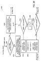
- the step of determining whether adjustment of the sole is required includes determining whether there is a change in a surface condition on which the article of footwear is used. In one embodiment, the step of determining whether there is a change in the surface condition on which the article of footwear is used includes determining whether there is a change in a first parameter over time and substantially no change in a second parameter over time.
- the step of determining whether there is a change in the surface condition on which the article of footwear is used includes determining whether there is a change in an absolute compression in the sole over time and substantially no change in a deviation of the compression in the sole over time, or alternatively, determining whether there is a change in the deviation of the compression in the sole over time and substantially no change in the absolute compression in the sole over time.
- the surface condition on which the article of footwear is used may be determined to have changed from a hard ground surface to a soft ground surface.
- the surface condition may be determined to have changed from a soft ground surface to a hard ground surface.
- the determination of whether there is a change in the surface condition on which the article of footwear is used is made after a wearer of the article of footwear has taken a plurality of steps.
- the step of determining whether adjustment of the sole is required includes determining that the compression in the sole is less than a lower threshold of compression. In such a case, the step of adjusting the sole includes softening the sole. Alternatively, in another embodiment, the step of determining whether adjustment of the sole is required includes determining that the compression in the sole is greater than an upper threshold of compression. In this latter case, the step of adjusting the sole includes hardening the sole. In one embodiment, the adjustment of the sole is made after a wearer of the article of footwear has taken a plurality of steps.
- the step of adjusting the sole may include actuating a motor located within the sole.
- the method further includes the step of determining the status of the motor located within the sole. Determining the status of the motor may include sampling a battery voltage or using a potentiometer, an encoder, or any other suitable type of measuring device.
- the invention in another aspect, relates to a controller for modifying a performance characteristic of an article of footwear during use.
- the controller includes a receiver configured to receive a first signal representing an output from a sensor at least partially disposed within a sole of the article of footwear, a determination module configured to determine whether the sole has compressed and to determine whether adjustment of the sole is required, and a transmitter configured to transmit a second signal for adjusting the sole.
- the invention in another aspect, relates to an article of footwear that includes an upper coupled to a sole and a controller at least partially disposed within the sole.
- the controller includes means for receiving a first signal representing an output from a sensor at least partially disposed within the sole, means for determining whether the sole has compressed and for determining whether adjustment of the sole is required, and means for transmitting a second signal for adjusting the sole.
- FIG. 1 is a partially exploded schematic perspective view of an article of footwear including an intelligent system in accordance with one embodiment of the invention
- FIG. 2A is an exploded schematic perspective view of a sole of the article of footwear of FIG. 1 in accordance with one embodiment of the invention
- FIG. 2B is an enlarged schematic side view of the intelligent system of FIG. 2A illustrating the operation of the adjustable element
- FIG. 3 is a schematic perspective view of an alternative embodiment of an adjustable element in accordance with the invention.
- FIGS. 4A-4E are schematic side views of alternative embodiments of an adjustable element in accordance with the invention.
- FIG. 5A is a schematic side view of the article of footwear of FIG. 1 showing select internal components
- FIG. 5B is an enlarged schematic view of a portion of the article of footwear of FIG. 5A;
- FIG. 6 is a schematic top view of a portion of the sole of FIG. 2A with a portion of the sole removed to illustrate the layout of select internal components of the intelligent system;
- FIG. 7 is an exploded schematic perspective view of a sole of the article of footwear of FIG. 1 in accordance with another embodiment of the invention.
- FIGS. 8A-8G are schematic perspective views of various components that may be included in various embodiments of the sole of FIG. 7 in accordance with the invention.
- FIG. 9 is a schematic bottom view of the midsole of FIGS. 7 and 8G in accordance with one embodiment of the invention.
- FIG. 10 is a schematic bottom view of an optional torsional bar that may be used with the sole of FIG. 7 in accordance with one embodiment of the invention.
- FIG. 11 is a schematic bottom view of the optional torsional bar of FIG. 10 disposed on the midsole of FIG. 9 in accordance with one embodiment of the invention.
- FIG. 12 is a schematic bottom view of the midsole and the optional torsional bar of FIG. 11, further including additional heel foam elements in accordance with one embodiment of the invention;
- FIG. 13 is a schematic bottom view of the midsole and the optional torsional bar of FIG. 11, further including additional components in accordance with one embodiment of the invention;
- FIG. 14 is a schematic bottom view of the midsole of FIG. 13 further including the additional heel foam elements of FIG. 12 in accordance with one embodiment of the invention.
- FIG. 15 is a schematic bottom view of the midsole of FIG. 14 further including a casing that covers the various components of the intelligent system in accordance with one embodiment of the invention
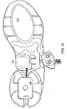
- FIG. 16 is a schematic lateral perspective view of a sole including a honeycombed shaped expansion element and a user interface in accordance with one embodiment of the invention
- FIG. 17 is a schematic lateral side view of the sole of FIG. 16;
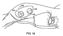
- FIG. 18 is an enlarged schematic lateral perspective view of the user interface of FIG. 16 in accordance with one embodiment of the invention.
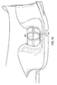
- FIG. 19 is an enlarged schematic lateral side view of the expansion element of FIG. 16 in accordance with one embodiment of the invention.
- FIG. 20 is a schematic perspective view of the expansion element of FIG.16 in accordance with one embodiment of the invention.
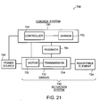
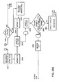
- FIG. 21 is a block diagram of an intelligent system in accordance with the invention.
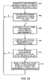
- FIG. 22 is a flow chart depicting one mode of operation of the intelligent system of FIG. 1;
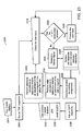
- FIG. 23 is a flow chart depicting an alternative mode of operation of the intelligent system of FIG. 1;
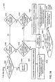
- FIG. 24 is a flow chart of a method for processing user inputs using the intelligent system of FIG. 1 in accordance with one embodiment of the invention.
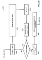
- FIG. 25 is a flow chart of a method for measuring a sensor signal using the intelligent system of FIG. 1 in accordance with one embodiment of the invention
- FIG. 26 is a flow chart of a method for determining whether a sole of an article of footwear has compressed using the intelligent system of FIG.1 in accordance with one embodiment of the invention
- FIG. 27 is a flow chart of a method for monitoring the sensor signal to detect a compression in a sole of an article of footwear using the intelligent system of FIG.1 in accordance with one embodiment of the invention
- FIG. 28 is a flow chart of a method for determining whether an adjustment of a sole of an article of footwear is required using the intelligent system of FIG. 1 in accordance with one embodiment of the invention
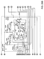
- FIG. 29 is a circuit diagram of one embodiment of the intelligent system of FIG. 1 for a left shoe
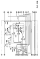
- FIG. 30 is a circuit diagram of one embodiment of the intelligent system of FIG. 1 for a right shoe;
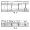
- FIG. 31 is a table that lists the states of the input/output at certain pins of the microcontroller of FIG. 29 that are required to turn on several combinations of the electro-luminescent elements of FIG. 29;
- FIG. 32 is a table that lists the output that is required at certain pins of the microcontroller of FIG. 29 to drive the motor of the intelligent system;
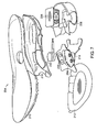
- FIG. 33A is a schematic side view of an article of footwear including an alternative embodiment of an intelligent system in accordance with the invention.
- FIG. 33B is a schematic perspective view of a portion of the intelligent system of FIG. 33A;
- FIG. 34A is a schematic side view of an article of footwear including yet another alternative embodiment of an intelligent system in accordance with the invention.
- FIGS. 34B-34D are schematic side views of the intelligent system of FIG. 34A in various orientations
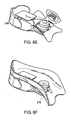
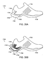
- FIG. 35A is a schematic side view of an article of footwear including yet another alternative embodiment of an intelligent system in accordance with the invention.
- FIG. 35B is a schematic side view of the intelligent system of FIG. 35A throughout a range of adjustment;
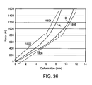
- FIG. 36 is a graph depicting a performance characteristic of a specific embodiment of an adjustable element
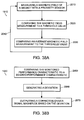
- FIG. 37 is a flow chart depicting one embodiment of a method of modifying a performance characteristic of an article of footwear during use
- FIGS. 38A and 38B are flow charts depicting additional embodiments of the method of FIG. 37.
- FIG. 39 is a flow chart depicting one embodiment of a method of providing comfort in an article of footwear.
- FIG. 1 depicts an article of footwear 100 including an upper 102, a sole 104, and an intelligent system 106.
- the intelligent system 106 is laterally disposed in a rearfoot portion 108 of the article of footwear 100.
- the intelligent system 106 could be disposed anywhere along the length of the sole 104 and in essentially any orientation.
- the intelligent system 106 is used to modify the compressibility of a heel area of the article of footwear 100.
- the intelligent system 106 can be located in a forefoot portion 109 and can be moved into and out of alignment with a flex line or otherwise configured to vary a push-off characteristic of the footwear 100.
- the footwear 100 could include multiple intelligent systems 106 disposed in multiple areas of the footwear 100.
- the intelligent system 106 is a self-adjusting system that modifies one or more performance characteristics of the article of footwear 100. The operation of the intelligent system 106 is described in detail hereinbelow.
- FIG. 2A depicts an exploded view of a portion of the sole 104 of FIG. 1.
- the sole 104 includes a midsole 110, an outsole 112a, 112b, an optional lower support plate 114, an optional upper support plate 116, and the intelligent system 106.
- the upper and lower support plates may, among other purposes, be included to help constrain the intelligent system 106 in a particular orientation.
- the intelligent system 106 is disposed within a cavity 118 formed in the midsole 110.
- the midsole 110 is a modified conventional midsole and has a thickness of about 10 mm to about 30 mm, preferably about 20 mm in the heel portion.
- the intelligent system 106 includes a control system 120 and an actuation system 130 in electrical communication therewith, both of which are described in greater detail hereinbelow.
- the actuation system 130 includes a driver 131 and an adjustable element 124.
- the control system 120 includes a sensor 122, for example a proximity sensor, a magnet 123, and electrical circuitry (see FIGS. 29-30).
- the sensor 122 is disposed below the adjustable element 124 and the magnet 123 is vertically spaced from the sensor 122.
- the magnet 123 is disposed above the adjustable element 124 and is a Neodymium Iron Bore type magnet.
- the sensor 122 and magnet 123 are located in a spot that corresponds generally to where maximum compression occurs in the rearfoot portion 108 of the footwear 100. Typically, the spot is under the wearer's calcaneous. In such an embodiment, the sensor 122 and magnet 123 are generally centered between a lateral side and a medial side of the sole 104 and are between about 25 mm and about 45 mm forward of a posterior aspect of the wearer's foot.
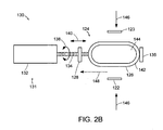
- FIG. 2B depicts a portion of the intelligent system 106, in particular the actuation system 130, in greater detail.
- the intelligent system 106 is preferably encased in a sealed, waterproof enclosure.
- the actuation system 130 generally includes a driver 131, which includes a motor 132 and a transmission element 134, and an adjustable element 124, which includes a limiter 128, an expansion element 126, and a stop 136.
- the embodiment of the particular driver 131 shown is a lead screw drive, made up of a bi-directional electric motor 132 and a threaded rod that forms the transmission element 134.
- the motor 132 can be a radio-controlled servomotor of the type used in model airplanes.
- the threaded rod could be made of steel, stainless steel, or other suitable material.
- the motor 132 is mechanically coupled to the transmission element 134 and drives the element 134 in either a clockwise or counter-clockwise direction as indicated by arrow 138.
- the transmission element 134 threadedly engages the limiter 128 and transversely positions the limiter 128 relative to the expansion element 126, as shown generally by arrow 140. Because the limiter 128 is threadedly engaged with the transmission element 134 and prevented from rotation relative to the motor 132 and the footwear 100, no power is required to maintain the limiter's position. There is sufficient friction in the actuation system 130 and a sufficiently fine thread on the transmission element 134 to prevent inadvertent rotation of the element 134 during a heel strike.
- the limiter 128 advances toward the expansion element 126 (forward) when the motor 132 drives the transmission element 134 in the clockwise direction and the limiter 128 moves away from the expansion element 126 (backward) when the motor 132 drives the transmission element 134 in the counter-clockwise direction.
- the driver 131 could be essentially any type of rotary or linear actuator, a gear train, a linkage, or combinations thereof.
- the expansion element 126 is generally cylindrical, with an elongated circular or elongated generally elliptically-shaped cross-section, or it includes a series of arched walls with different centers, but identical radii, or any combination thereof.
- the arcuate ends of the expansion elements are not necessarily semi-circular in shape.
- the radius of the arcuate ends will vary to suit a particular application and can be varied to control the amount of longitudinal expansion of the expansion element 126 when under compressive loading vertically. In general, the larger the radius of the arcuate end, the greater longitudinal expansion is possible under vertical compression loading.
- the expansion element 126 has a solid outer wall 142 and a optional compressible core 144 of foam or other resilient material.
- the transmission element 134 extends through the expansion element 126 and connects to a stop 136.
- the stop 136 prevents movement of the expansion element 126 in a direction away from the limiter 128.
- the stop 136 could be a rear wall of the cavity 118.
- the general operation of the adjustable element 124 is described with respect to an application where the intelligent system 106 is used to modify cushioning in the article of footwear 100 in response to a measured parameter, for example compression of the midsole 110.
- the expansion element 126 is allowed to compress when acted on by a vertical force, depicted generally by arrows 146.
- the expansion element 126 expands in the horizontal direction (arrow 148) when compressed.
- the limiter 128 is used to control this movement. As the horizontal movement is limited, the vertical movement is limited as well.
- the expansion element 126 has a bi-modal compression response, which is discussed in greater detail below with respect to FIG. 36.
- the intelligent system 106 can control the amount of compression a user creates in the article of footwear 100.
- the vertical force 146 is applied to the expansion element 126 via the sole 104.
- the force 146 causes the expansion element 126 to expand during ground contact until it contacts the limiter 128, thereby controlling the compression of the sole 104.
- the sensing portion of the control system 120 measures field strength of the magnet 123.
- the sensor 122 is disposed proximate the bottom of the midsole 110 and the magnet 123 is disposed proximate the top of the midsole 110.
- the magnetic field strength detected by the sensor 122 changes as the magnet 123 moves closer to the sensor 122, as the midsole 110 is compressed.
- the system can be calibrated, such that this magnetic field strength can be converted to a distance. It is the change in distance that indicates how much the midsole 110 has been compressed.
- the control system 120 outputs a signal to the actuation system 130 based on the change in distance or compression measurement.
- the actuation system 130 modifies the hardness or compressibility of the midsole 110 based on the signal received from the control system 120.
- the actuation system 130 utilizes the transmission element 134 as the main moving component. The operation of the intelligent system 106 is described in greater detail below, with respect to the algorithms depicted in FIGS. 22-28.
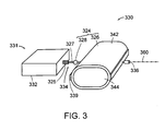
- FIG. 3 depicts a portion of an alternative embodiment of an intelligent system 306 in accordance with the invention, in particular the actuation system 330.
- the actuation system 330 includes a driver 331 and an adjustable element 324.
- the adjustable element 324 includes an expansion element 326 and limiter 328 similar to that described with respect to FIG. 2B.
- the driver 331 includes a motor 332 and a transmission element 334, in this embodiment a hollow lead screw 325 through which a cable 327 passes.
- the cable 327 runs through the expansion element 326 and has a stop 336 crimped to one end.
- the limiter 328 is a generally cylindrically-shaped element that is slidably disposed about the cable 327 and acts as a bearing surface between the screw 325 and the expansion element 326, in particular a bearing arm 339 coupled to the expansion element 326. A similar bearing arm is disposed proximate the stop 336, to distribute loads along the depth of the expansion element 326.
- the motor 332 is a 8-10 mm pager motor with a 50:1 gear reduction.
- the cable 327, screw 325, limiter 328, and bearing arm 339 may be made of a polymer, steel, stainless steel, or other suitable material.
- the cable 327 is made from stainless steel coated with a friction-reducing material, such as that sold by DuPont under the trademark Teflon® .
- the cable 327 is fixedly attached to the driver 331 and has a fixed length.
- the cable 327 runs through the screw 325, which determines the amount of longitudinal travel of the expansion element 326 that is possible. For example, as a vertical force is applied to the expansion element 326, the element 326 expands longitudinally along the cable 327 until it hits the limiter 328, which is disposed between the expansion element 326 and the end of the screw 325.
- the motor 332 rotates the screw 325 to vary the length of the cable 327 that the limiter 328 can slide along before contacting the screw 325 and expansion element 326.
- the screw 325 moves a predetermined distance either towards or away from the element 326 in response to the signal from the control system. In one embodiment, the screw 325 may travel between about 0 mm to about 20 mm, preferably about 0 mm to about 10 mm.
- the adjustable element 324 includes two motors 332 and cables 327 oriented substantially parallel to one another. Two cables 327 aid in holding the expansion element 326 square relative to a longitudinal axis 360 of the adjustable element 324 depicted in FIG. 3.
- other types of expansion element/limiter arrangements are possible.
- a circumferential or belly band type limiter may be used instead of a diametral or longitudinal type limiter.
- the driver 331 varies the circumference of the belly band to vary the range of expansion of the element 326, the larger the circumference, the larger the range of expansion.
- Other possible arrangements include shape memory alloys and magnetorheological fluid.
- FIGS. 4A-4E depict alternative adjustable elements, with each shown in an unloaded state.
- FIGS. 4A-4D depict certain different possible shapes for the expansion element.
- the expansion element 426 includes two cylinders 428 having generally elliptically-shaped cross-sections and formed as a single element.
- the cylinder cross-sectional shape could be any combination of linear and arcuate shapes, for example, hexagonal or semi-circular.
- the cylinders 428 include a wall 432 and a pair of cores 434 that may be hollow or filled with a foam or other material.
- FIG. 4B depicts an expansion element 446 having two separate cylinders 448 having generally circular cross-sections and coupled together.
- FIG. 4C depicts an expansion element 466 including two cylinders 448 as previously described.
- the expansion element 466 includes a foam block 468 surrounding the cylinders 448.
- the foam block 468 may replace the core or be additional to the core.
- FIG. 4D depicts yet another embodiment of an expansion element 486.
- the expansion element 486 includes a cylinder 488 having an elongate sector cross-sectional shape.
- the cylinder includes a wall 492 and a core 494.
- the cylinder 488 includes a first arcuate end 496 and a second arcuate end 498.
- the first arcuate end 496 has a substantially larger radius than the second arcuate end 498, thereby resulting in greater horizontal displacement at the first arcuate end when under load.
- the wall thickness of any cylinder can be varied and/or the cylinder could be tapered along its length.
- FIG. 4E depicts an alternative type of adjustable element 410.
- the adjustable element 410 includes a relatively flexible structural cylinder 412 and piston 414 arrangement.
- the internal volume 416 of the cylinder 412 varies as the piston 414 moves into and out of the cylinder 412, shown generally by arrow 418.
- the piston 414 is moved linearly by the driver 131 in response to the signal from the control system 120.
- the volume 416 By varying the volume 416, the compressibility of the cylinder 412 is varied. For example, when the piston 414 is moved into the cylinder 412, the volume is reduced and the pressure within the cylinder is increased; the greater the pressure, the harder the cylinder. While this system may appear similar to that of an inflatable bladder, there are differences.
- the amount of fluid e.g. , air
- bladders primarily react based on the pressure within the bladder, whereas the element 410 depicted in FIG. 4E uses the structure of the cylinder in combination with the internal pressure.
- the two are fundamentally different in operation.
- the inflatable bladder like a balloon, merely holds the air in and provides no structural support, while the cylinder, like a tire, uses the air to hold up the structure (e.g. the tire sidewalls).
- the piston 414 and driver 131 arrangement allows for fine adjustment of the pressure and compressibility of the adjustable element 410.
- FIG. 5A depicts a side view of the article of footwear 100 of FIG.1.
- the intelligent system 106 is disposed generally in the rearfoot portion 108 of the article of footwear 100.
- the intelligent system 106 includes the adjustable element 124 with the limiter 128 and the driver 131.
- a user-input module 500 (FIG. 5B) including user-input buttons 502, 504 and an indicator 506.
- the user can set the compression range or other performance characteristic target value of the article of footwear 100, by pushing input button 502 to increase the target value or pushing input button 504 to decrease the target value or range.
- the user-input module 500 can be remotely located from the shoe.
- a wristwatch, personal digital assistant (PDA), or other external processor could be used alone or in combination with the user-input module 500 disposed on the article of footwear, to allow the user to customize characteristics of the intelligent system 106.
- the user may press buttons on the wristwatch to adjust different characteristics of the system 106.
- the system 106 may include an on and off switch.
- the user-input module 506 is shown in greater detail in FIG. 5B.
- the indicator(s) 506 may be one or more electro-luminescent elements, for example.
- the indicator 506 is a series of electro-luminescent elements printed on a flex-circuit that glow to indicate the range of compression selected; however, the indicators could also indicate the level of hardness of the midsole or some other information related to a performance characteristic of the footwear 100. Alternatively or additionally, the indicator may be audible.
- FIG. 6 depicts a top view of one possible arrangement of select components of the intelligent system of FIG. 1.
- the adjustable element 124 is disposed in the rearfoot portion 108 of the midsole 110 with the expansion element 126 laterally disposed within the cavity 118.
- the driver 131 is disposed adjacent to the expansion element 126. Adjacent to the driver 131 is the control system 120.
- the control system 120 includes a control board 152 that holds a microcontroller for controlling the driver 131 and for processing the algorithm.
- the system 106 includes a power source 150, for example a 3.0V 1 ⁇ 2 AA battery.
- the power source 150 supplies power to the driver 131 and the control system 120 via wires 162 or other electrical connection, such as a flexcircuit.
- the system 106 further includes the magnet 123 and the aligned sensor 122 (not shown), which is located under the expansion element 126 and is electrically coupled to the control system 120.
- the magnet 123 is located above the expansion element 126, but below an insole and/or sock liner.
- the entire intelligent system 106 can be built into a plastic casing to make the system 106 waterproof.
- the system 106 can be built as a single module to facilitate fabrication of the sole 104 and may be pre-assembled to the lower support plate 114 (not shown in FIG. 6).
- the system 106 is removable, thereby making the system 106 replaceable.
- the outsole 112a, 112b may be configured ( e.g. , hinged) to allow the system to be removed from the cavity 118 of the midsole 110.
- the system 106 may also include an interface port 160 that can be used to download data from the intelligent system 106, for example to a PDA or other external processor.
- the port 106 can be used to monitor shoe performance.
- the data can be transmitted (e.g., via radio waves) to a device with a display panel located with the user.
- the data can be transmitted to a wristwatch or other device being worn by the user.
- the user may adjust certain characteristics of the shoe by pressing buttons on the wristwatch, as described above. These adjustments are transmitted back to the system 106 where the adjustments are implemented.
- FIG. 7 depicts an exploded perspective view of a sole 204 of the article of footwear 100 of FIG. 1 in accordance with another embodiment of the invention.
- the sole 204 includes a midsole 210, an outsole 212, an optional lower support plate 214, and an optional upper support plate 216.
- a rearfoot portion 208 of the sole 204 may be made from, for example, a foam, such as a polyurethane (PU) or ethylene vinyl acetate (EVA) foam, and may be adapted to receive an expansion element 226.
- PU polyurethane
- EVA ethylene vinyl acetate
- the expansion element 226 is, as shown, shaped like a honeycomb; however, the element 226 may also be generally cylindrical, with an elongated circular or elongated generally elliptically-shaped cross-section, or include a series of arched walls with different centers, but identical radii, or any combination thereof.
- a motor 232 is also positioned within the sole 204 and may be used to adjust the expansion element 226.
- a user interface 254, including user input buttons 256, may also be provided for receiving user inputs related to the adjustment of the sole 204.
- FIGS. 8A-8G depict perspective views of various components that may be included in various embodiments of the sole 204.
- the components include the motor 232 (FIG. 8A), the expansion element 226 (FIG. 8B), the optional lower support plate 214 (FIG. 8C), the user interface 254 and the user input buttons 256 (FIG. 8D), the rearfoot portion 208 that may be made from, for example, the PU or EVA foam (FIG. 8E), the optional upper support plate 216 (FIG. 8F), and the midsole 210 (FIG. 8G).
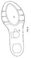
- FIG. 9 depicts a bottom view of the midsole 210 of FIGS. 7 and 8G.
- the midsole 210 includes an opening 257 for accessing the power source 150 (see FIG. 6) and related equipment used in the intelligent system 106.
- the position of the opening 257 in the midsole 210 can vary depending on the location of the power source 150 and related equipment in the sole 204.
- FIG. 10 depicts a bottom view of an optional torsional bar 258 that may be used with the sole 204 of FIG. 7 in accordance with one embodiment of the invention.
- the torsional bar 258 may include openings 264a, 264b at the heel and at the shank.
- the openings 264 may provide clearance for, or access to, the various components of the intelligent system 106.
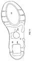
- FIG. 11 depicts a bottom view of the optional torsional bar 258 of FIG. 10 disposed on the midsole 210 illustrated in FIG. 9 in accordance with one embodiment of the invention.
- the opening 264b on the torsional bar 258 aligns with the opening 257 in the midsole 210 to enable a user to access the power source 150 and related equipment in the sole 204.
- FIG. 12 depicts a bottom view of the midsole 210 and the optional torsional bar 258 of FIG. 11, further including additional heel foam elements 266a, 266b, 266c in accordance with one embodiment of the invention.
- the illustrated embodiment includes three heel foam elements: (1) a rear foam element 266a extending from a medial to a lateral side of the midsole 210; (2) a medial front foam 266b element; and (3) a lateral front foam element 266c.
- the hardness of the foam elements 266 may vary to suit a particular application.
- the lateral front foam element 266c may be harder than the rear foam element 266a.
- the material properties may vary between and within the different foam elements 266 to perform different functions, for example, to guide the foot into a neutral position between pronation and supination during a step cycle.
- foam elements for cushioning and guidance is described in greater detail in U.S. Patent No. 6,722,058 and U.S. Patent Application Serial No.10/619,652.
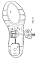
- FIG. 13 depicts a bottom view of the midsole 210 and the optional torsional bar 258 of FIG. 11, further including the motor 232 and the power source 150 disposed in the openings 257, 264b that extend through the midsole 210 and optional torsional bar 258, the user interface 254, and the expansion element 226 in accordance with one embodiment of the invention.
- the expansion element 226 could be located in the forefoot area of the sole 204, or at substantially any position along the sole 204.
- the orientation of the expansion element 226 in the sole 204 can be varied to suit a particular application.
- the intelligent system could be located on only the medial or lateral side to provide a controlled dual density sole, one part of which would be automatically adjustable.
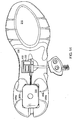
- FIG. 14 depicts a bottom view of the midsole 210 of FIG. 13 further including the additional heel foam elements 266a, 266b, 266c of FIG. 12 in accordance with one embodiment of the invention.
- the expansion element 226 is shown embedded between the three foam elements 266a, 266b, 266c.
- FIG. 15 depicts a bottom view of the midsole 210 of FIG. 14 further including a casing 270 that covers the power source 150 and other electronic components in accordance with one embodiment of the invention.
- the casing 270 can optionally be removed to enable a user to access the power source 150 and other electronic equipment.
- FIG. 16 is a lateral perspective view of the sole 204 including the honeycombed shaped expansion element 226 and the user interface 254 that may be used to alter the settings of the intelligent system 106 in accordance with one embodiment of the invention.
- the sole 204 can include multiple expansion elements 226.
- a cable element (not shown) may extend between the medial front foam element 266b and the lateral front foam element 266c, and also between the rear foam elements 266a.
- the expansion elements 226 can be coupled together by the cable passing therethrough.
- the user interface 254 includes buttons 256 to increase (+) and/or decrease (-) the performance characteristic(s) of the intelligent system 106 and electro-luminescent elements 268 to indicate the system setting.
- FIG. 17 is a lateral side view of the sole 204 of FIG. 16, where the expansion element 226 is more fully illustrated.
- the expansion element 226 is, as shown, shaped like a honeycomb; however, the element 226 may also be generally cylindrical, with an elongated circular or elongated generally elliptically-shaped cross-section, or include a series of arched walls with different centers, but identical radii, or any combination thereof.
- FIG. 18 is an enlarged lateral view of the user interface 254 of FIG. 16 illustrating the buttons 256 that are used to increase (+) and/or decrease (-) the performance characteristic(s) provided by the intelligent system 106 and the electro-luminescent elements 268 that indicate the system setting in accordance with one embodiment of the invention.
- FIG. 19 is an enlarged lateral side view of the expansion element 226 of FIG. 16 illustrating its honeycomb shape in accordance with one embodiment of the invention.
- a cable 327 is shown running through the middle of the expansion element 226.
- FIG. 20 depicts a perspective view of the expansion element 226 of FIG. 16 in accordance with one embodiment of the invention.
- the expansion element 226 has four generally vertical side walls 272 (two on each side), whereby a generally horizontal bar 274 connects the adjacent side walls 272 on each side to each other, thereby forming the generally honeycomb-like structure.
- the horizontal bar 274 is generally centrally disposed between the side walls 272.
- the horizontal bars 274 provide stability against shear forces in a longitudinal direction and in some instances may be under tension.
- the side walls 272 have a generally arcuate shape; however, the side walls 272 and the horizontal bar 274 can be linear, arcuate, or combinations thereof.
- the expansion element 226 may also include a top bar 276 and a bottom bar 278.
- the intelligent system 706 includes a power source 750 electrically coupled to a control system 720 and an actuation system 730.
- the control system 720 includes a controller 752, for example one or more micro-processors, and a sensor 722.
- the sensor may be a proximity-type sensor and magnet arrangement.
- the controller 152 is a microcontroller such as the PICMicro® microcontroller manufactured by Microchip Technology Incorporated of Chandler, Arizona.
- the controller 752 is a microcontroller manufactured by Cypress Semiconductor Corporation.
- the actuation system 730 includes a driver 731, including a motor 732 and a transmission element 734, and an adjustable element 724.
- the driver 731 and control system 720 are in electrical communication.
- the adjustable element 724 is coupled to the driver 731.
- the actuation system 730 could include a feedback system 754 coupled to or as part of the control system 720.
- the feedback system 754 may indicate the position of the adjustable element 724.
- the feedback system 754 can count the number of turns of the motor 732 or the position of the limiter 728 (not shown).
- the feedback system 754 could be, for example, a linear potentiometer, an inductor, a linear transducer, or an infrared diode pair.
- FIG. 22 depicts one possible algorithm for use with the intelligent system 106.
- the intelligent system 106 measures a performance characteristic of a shoe during a walk/run cycle. Before the system 106 begins to operate, the system 106 may run a calibration procedure after first being energized or after first contacting the ground surface. For example, the system 106 may actuate the adjustable element 124 to determine the position of the limiter 128 and/or to verify the range of the limiter 128, i.e., fully open or fully closed. During operation, the system 106 measures a performance characteristic of the shoe (step 802). In one embodiment, the measurement rate is about 300Hz to about 60 KHz. The control system 120 determines if the performance characteristic has been measured at least three times (step 804) or some other predetermined number.
- step 802 the system 106 repeats step 802 by taking additional measurements of the performance characteristic until step 804 is satisfied.
- the system 106 averages the last three performance characteristic measurements (step 806).
- the system 106 compares the average performance characteristic measurement to a threshold value (step 808).
- the system 106 determines if the average performance characteristic measurement is substantially equal to the threshold value. If the average performance characteristic measurement is substantially equal to the threshold value, the system 106 returns to step 802 to take another performance characteristic measurement. If the average performance characteristic measurement is not substantially equal to the threshold value, the system 106 sends a corrective driver signal to the adjustable element 124 to modify the performance characteristic of the shoe.
- the intelligent system 106 then repeats the entire operation until the threshold value is reached and for as long as the wearer continues to use the shoes.
- the system 106 only makes incremental changes to the performance characteristic so that the wearer does not sense the gradual adjustment of the shoe and does not have to adapt to the changing performance characteristic. In other words, the system 106 adapts the shoe to the wearer, and does not require the wearer to adapt to the shoe.
- the system 106 utilizes an optimal midsole compression threshold (target zone) that has been defined through testing for a preferred cushioning level.
- the system 106 measures the compression of the midsole 110 on every step, averaging the most recent three steps. If the average is larger than the threshold then the midsole 110 has over-compressed. In this situation, the system 106 signals the driver 131 to adjust the adjustable element 124 in a hardness direction. If the average is smaller than the threshold, then the midsole 110 has under-compressed. In this situation, the system 106 signals the driver 131 to adjust the adjustable element in a softness direction. This process continues until the measurements are within the target threshold of the system. This target threshold can be modified by the user to be harder or softer. This change in threshold is an offset from the preset settings. All of the above algorithm is computed by the control system 120.
- the overall height of the midsole 110 and adjustable element 124 is about 20 mm.
- an optimal range of compression of the midsole 110 is about 9 mm to about 12 mm, regardless of the hardness of the midsole 110.
- the limiter 128 has an adjustment range that corresponds to about 10 mm of vertical compression.
- the limiter 128, in one embodiment, has a resolution of less than or equal to about 0.5 mm.
- the wearer may vary the compression range to be, for example, about 8 mm to about 11 mm or about 10 mm to about 13 mm. Naturally, ranges of greater than 3 mm and lower or higher range limits are contemplated and within the scope of the invention.
- the wearer's foot goes through a stride cycle that includes a flight phase (foot in the air) and a stance phase (foot in contact with the ground).
- the flight phase accounts for about 2/3 of the stride cycle.
- the wearer's body is normally adapting to the ground contact.
- all measurements are taken during the stance phase and all adjustments are made during the flight phase. Adjustments are made during the flight phase, because the shoe and, therefore, the adjustable element are in an unloaded state, thereby requiring significantly less power to adjust than when in a loaded state.
- the shoe is configured such that the motor does not move the adjustable element, therefore lower motor loads are required to set the range of the adjustable element.
- the adjustable element does move, as described in greater detail hereinbelow.
- the system 106 senses that the shoe has made contact with the ground. As the shoe engages the ground, the sole 104 compresses and the sensor 122 senses a change in the magnetic field of the magnet 123. The system 106 determines that the shoe is in contact with the ground when the system 106 senses a change in the magnetic field equal to about 2 mm in compression. It is also at this time that the system 106 turns off the power to the actuation system 130 to conserve power. During the stance phase, the system 106 senses a maximum change in the magnetic field and converts that measurement into a maximum amount of compression. In alternative embodiments, the system 106 may also measure the length of the stance phase to determine other performance characteristics of the shoe, for example velocity, acceleration, and jerk.
- the sole 104 has over-compressed, and if the maximum amount of compression is less than 9 mm, then the sole 104 has under-compressed. For example, if the maximum compression is 16 mm, then the sole 104 has over-compressed and the control system 120 sends a signal to the actuation system 130 to make the adjustable element 124 firmer.
- the actuation system 130 operates when the shoe is in the flight phase, i.e. , less than 2 mm of compression. Once the system 106 senses that the compression is within the threshold range, the system 106 continues to monitor the performance characteristic of the shoe, but does not further operate the actuation system 130 and the adjustable element 124. In this way, power is conserved.
- the intelligent system 106 can use additional performance characteristics alone or in combination with the optimal midsole compression characteristic described above.
- the system 106 can measure, in addition to compression, time to peak compression, time to recovery, and the time of the flight phase. These variables can be used to determine an optimum setting for the user, while accounting for external elements such as ground hardness, incline, and speed. Time to peak compression is described as the amount of time that it takes from heel strike to the maximum compression of the sole while accounting for surface changes. It may be advantageous to use the area under a time versus compression curve to determine the optimum compression setting. This is in effect a measure of the energy absorbed by the shoe.
- the time of the flight phase (described above) can contribute to the determination of the optimum setting.
- the stride frequency of the user can be calculated from this variable. In turn, stride frequency can be used to determine changes in speed and to differentiate between uphill and downhill motion.
- FIG. 23 depicts another possible algorithm that may be performed by the intelligent system 106.
- FIG. 23 illustrates one embodiment of a method 2300 for modifying a performance characteristic of the article of footwear 100 during use.
- the intelligent system 106 measures a sensor signal from the sensor 122.
- the intelligent system 106 determines, at step 2600, whether the sole 104 has compressed.
- the intelligent system 106 performs initial calculations, at step 2700, to determine whether an adjustment of the sole 104 is required.
- the intelligent system 106 performs additional calculations to determine further or alternatively whether an adjustment of the sole 104 is required.
- the intelligent system 106 also adjusts the sole 104 at step 2800.
- FIGS. 25, 26, 27, and 28, which follow, describe methods for implementing the steps 2500, 2600, 2700, and 2800, respectively, of the method 2300.
- the method 2300 begins by providing power to the intelligent system 106.
- a battery may act as the power source 150 and may be installed in the intelligent system 106 at step 2304. Once the battery is installed in the intelligent system 106, the intelligent system 106 may run an "ON" sequence at step 2308. For example, the intelligent system 106 may light the electro-luminescent elements of the indicator 506 in a manner that signals to a user of the article of footwear 100 that the intelligent system 106 is active.
- the user may turn the intelligent system 106 on and activate the "ON" sequence by pressing, for example, one or more of the user-input buttons 502, 504 at step 2312.
- the intelligent system 106 may check for user input at step 2316.
- the user indicates a desire to increase hardness of the sole 104 by pressing the "+" button 502, and a desire to decrease the hardness of the sole 104 (i.e., increase the softness of the sole 104) by pressing the "-" button 504.
- the intelligent system 106 processes the user input at step 2400.
- the method 2300 may include a self diagnostic and user analysis/interaction step 2324. More specifically, at step 2324, the intelligent system 106 may diagnose itself by checking several parameters of the intelligent system 106 described herein, including, but not limited to, the sensor condition and/or output, the battery strength, the motor direction, the condition of the voltage reference that may be used in step 2500, and the presence or absence of user-input from buttons 502, 504. Moreover, at step 2324, a user of the article of footwear 100 may read data from the intelligent system 106 or perform other functions. In one embodiment, a special key is used to access the intelligent system 106.
- the intelligent system 106 may be able to track or monitor the athletic performance of a wearer of the article of footwear 100, such as, for example, the distance traveled by the wearer, the wearer's pace, and/or the wearer's location. In such an embodiment, this information may be accessed at step 2324.
- the intelligent system 106 cycles through the steps of the method 2300 by following the directions of the arrows indicated in FIG. 23, with each particular step along the way being performed or not depending on the value of certain parameters. In addition, in one particular embodiment, the intelligent system 106 cycles through steps 2316, 2320, 2500, 2324, 2600, 2700, and 2800 at a rate between about 300Hz and about 400Hz.
- a microcontroller of the intelligent system 106 performs many of the steps described with respect to FIGS. 23-28.
- the microcontroller may include, for example, a receiver that is configured to receive a first signal representing an output from the sensor 122, a determination module that is configured to determine whether the sole 104 has compressed and to determine whether adjustment of the sole 104 is required, and a transmitter that is configured to transmit a second signal for adjusting the sole 104.
- the intelligent system 106 determines, at step 2320, that a user has entered input, the intelligent system 106 processes such user input at step 2400.
- FIG. 24 which depicts one embodiment of a method 2400 for processing the user input
- the intelligent system 106 calls the "OFF" sequence at step 2404.
- the intelligent system 106 runs the "OFF" sequence at step 2328.
- the intelligent system 106 in running the "OFF" sequence, the intelligent system 106 lights the electro-luminescent elements of the indicator 506 in a manner that signals to a user of the article of footwear 100 that the intelligent system 106 is being turned off. The intelligent system 106 may then enter an "OFF” or "DEEP SLEEP” mode at step 2332 until it is again activated by the user at step 2312.
- the sole 104 of the article of footwear 100 may include a number of hardness settings, and the intelligent system 106 may be configured to change the hardness setting for the sole 104 in response to receiving the user input.
- the hardness setting for the sole 104 is a user adjustable parameter
- changing the hardness setting for the sole 104 does not necessarily lead to an adjustment of the sole 104 itself (e.g., a softening or hardening of the sole 104).
- Whether or not the sole 104 is itself adjusted depends in part on the hardness setting, but also on many other variables, and is not determined until steps 2700 and 2800 described below.
- the number of hardness settings for the sole 104 is between five and 20. If the user has pressed only the "-" button 504 (decided at step 2406), the intelligent system 106 determines, at step 2408, whether the current hardness setting for the sole 104 can be changed to a softer setting. If so (i.e., if the hardness setting for the sole 104 is not currently set to its softest setting), the intelligent system 106 changes the hardness setting for the sole 104 to a softer setting at step 2412. Similarly, if the user has pressed only the "+" button 502 (decided at step 2414), the intelligent system 106 determines, at step 2416, whether the current hardness setting for the sole 104 can be changed to a harder setting. If so (i.e., if the hardness setting for the sole 104 is not currently set to its hardest setting), the intelligent system 106 changes the hardness setting for the sole 104 to a harder setting at step 2420.
- the intelligent system 106 calculates, either at step 2424 or at step 2428, at least one new threshold of compression in response to receiving the user input. In one embodiment, the intelligent system 106 calculates both a new lower threshold of compression and a new upper threshold of compression. Each new threshold of compression may be calculated by taking into account, for example, a previous value for that threshold of compression, the new hardness setting for the sole 104 (determined either at step 2412 or at step 2420), and one or more constants. In one embodiment, each threshold of compression is used in determining, at step 2800, whether the adjustment of the sole 104 is required.
- step 2424 or step 2428 is complete, or if it was determined either at step 2408 or at step 2416 that the hardness setting for the sole 104 could not be changed, the intelligent system 106 displays the new (current) hardness setting for the sole 104 at step 2432. In one embodiment, the intelligent system 106 displays the new (current) hardness setting for the sole 104 by activating at least one electro-luminescent element of the indicator 506.
- the intelligent system 106 ends, at step 2436, the display of the new (current) hardness setting by, for example, deactivating (e.g., fading) the one or more activated electro-luminescent elements of the indicator 506.
- the intelligent system 106 then returns to step 2316 of FIG. 23.
- the intelligent system 106 may first set, at step 2504, the instruction clock (e.g., slow down the instruction clock) of the microcontroller that implements many of the steps in the methods of FIGS. 23-28 to, for example, 1 MHz.
- the microcontroller's instruction clock is set to 1 MHz to conserve battery power and does not relate to the rate at which the signal from the sensor 122 is sampled. Alternatively, the microcontroller's instruction clock may be set to a different frequency to conserve battery power.
- the signal from the sensor 122 is sampled at step 2508.
- the sensor 122 is a hall effect sensor that measures a magnetic field and that outputs an analog voltage representative of the strength of the magnetic field. Accordingly, in one embodiment of step 2508, the analog voltage is sampled, compared to a voltage reference, and converted to a digital value using an A/D converter. In the embodiments described herein, a smaller digital value represents a stronger magnetic field and, therefore, a greater amount of compression in the sole 104.
- the sensor 122 which in one embodiment has the greatest settling time, is turned on first.
- the A/D converter which in one embodiment has the second greatest settling time, is then turned on.
- the electrical devices implementing the voltage reference are turned on.
- the analog voltage output by the sensor 122 is then sampled, compared to the voltage reference, and converted to a digital value using an A/D converter.
- the sensor 122 is then turned off to conserve energy.
- the electrical devices implementing the voltage reference are turned off to also conserve energy and, lastly, the A/D converter is turned off to conserve energy.
- the sensor 122, the A/D converter, and the electrical devices implementing the voltage reference may be turned on and/or off in other orders, and may even be turned on and/or off substantially simultaneously.
- n 1 which is initially set to zero and represents the number of samples taken, is incremented at step 2512.
- the digital value representative of the strength of the magnetic field sampled at step 2508 is then stored in the microcontroller's memory at step 2516.
- the counter "n 1 " is compared to a first constant to determine whether the number of samples taken is greater than the first constant. If so, the microcontroller's instruction clock is reset to, for example, 4 MHz and the counter "n 1 " is reset to zero at step 2524. Otherwise, steps 2504, 2508, 2512, 2516, and 2520 are repeated.
- the intelligent system 106 is sure to sample the sensor signal a plurality of times. Typically, the value of the first constant is between two and ten.
- a measurement of the sensor signal is determined.
- the measurement of the sensor signal is determined by calculating the average of the plurality of samples of the sensor signal taken in repeating step 2508.
- the measurement of the sensor signal is determined by, for example, averaging a subset of the plurality of samples of the sensor signal taken in repeating step 2508.
- the lowest and highest sampled values of the sensor signal are discarded, and the remaining sampled values of the sensor signal are averaged to determine the measurement of the sensor signal.
- FIG. 26 depicts one embodiment of a method 2600 for determining whether the sole 104 of the article of footwear 100 has compressed.
- the method 2600 is only performed if the parameter compression flag ("COMPFLAG") is set to 0, indicating that the intelligent system 106 has not yet detected compression in the sole 104.
- the parameter "COMPFLAG” is initially set to 0.
- a counter "FIRSTTIME” is compared to a second constant. The counter "FIRSTTIME” is incremented each time step 2500 (see FIGS. 23 and 25) is completed (i.e., each time a measurement of the sensor signal is determined).
- the microcontroller employs a first-in-first-out (FIFO) buffer that is capable of storing a pre-determined number of measurements of the sensor signal, for example between ten and 30.
- FIFO first-in-first-out
- step 2612 If the counter "FIRSTTIME" is greater than the second constant, the intelligent system 106 proceeds to perform step 2612.
- the value for the second constant is between 15 and 30.
- step 2500 i.e., the step of measuring the sensor signal
- step 2500 is guaranteed to be repeated a plurality of times to obtain a plurality of measurements of the sensor signal before the intelligent system 106 proceeds to step 2612.
- an average of a plurality of previously obtained measurements of the sensor signal (each measurement of the sensor signal being previously determined at step 2528 of FIG. 25 and stored in the microcontroller's memory at step 2608) is calculated at step 2612.
- the measurement of the sensor signal most recently determined at step 2528 is not, however, included in the calculation of this average.
- a parameter "valdiff" which represents the difference between the average calculated at step 2612 and the measurement of the sensor signal most recently determined at step 2528, is then determined at step 2616.
- the parameter '"valdiff" is then compared to a third constant at step 2620.
- the intelligent system 106 increments a counter "n 2 " at step 2624, which is initially set to zero. Otherwise, if the parameter "valdiff" is less than the third constant, the intelligent system 106 returns to step 2608 to store the most recently obtained measurement of the sensor signal in the microcontroller's memory and to reset the counter "n 2 " to zero.
- the value for the third constant may vary depending on, for example, the thickness of the midsole, the noise of the sensor signal, and/or the sampling rate (8bit or 16bit). For example, the value for the third constant may be between 2 and 16 for an 8bit system and between 2 and 64 for a 16bit system.
- the counter "n 2 " is compared to a fourth constant. If the counter "n 2 " is greater than the fourth constant, the intelligent system 106 determines that the sole 104 has compressed and sets the parameter "COMPFLAG" equal to 1 at step 2632. The intelligent system 106 also sets, at step 2632, the parameter "peak” equal to the most recently determined measurement of the sensor signal, and increments the counter "STEP", which is described below.
- the fourth constant of step 2628 is chosen so that the comparison of step 2620 must be true a number of consecutive times before the intelligent system 106 will determine the sole 104 to have compressed and, consequently, proceed to step 2632.
- the fourth constant is between two and five. With the fourth constant set equal to five, for example, step 2620 would need to be true six consecutive times for the intelligent system 106 to determine that the sole 104 of the article of footwear 100 has compressed and, consequently, proceed to step 2632.
- step 2608 or 2632 Upon completion of step 2608 or 2632, or where the counter "n 2 " is not greater than the fourth constant, the intelligent system 106 moves on to step 2700.
- FIG. 27 depicts one embodiment of a method 2700 for performing initial calculations to determine whether an adjustment of the sole 104 of the article of footwear 100 is required.
- the method 2700 is only performed if the parameter "COMPFLAG" is set to 1, meaning that the intelligent system 106 has detected compression in the sole 104.
- the method 2700 is only performed if step 2632 of method 2600 has been performed.
- another measurement of the sensor signal is obtained (i.e., the method 2500 of FIG. 25 is again performed) before the method 2700 is performed.
- the intelligent system 106 first increments, on each iteration through the steps of the method 2700, a timer at step 2704. If the timer is greater than a chosen maximum value, indicating that step 2712 of the method 2700 is continually being repeated, the intelligent system 106 proceeds to re-set both the parameter "COMPFLAG" and the timer to zero at step 2708. Otherwise, if the timer is less than the chosen maximum value, the intelligent system proceeds to step 2712.
- the intelligent system 106 determines the maximum amount of measured compression in the sole 104. Specifically, the intelligent system 106 determines, at step 2712, the real peak value for the amount of compression in the sole 104. In one embodiment, the intelligent system 106 does so by determining if the sole 104 is still compressing. More specifically, the intelligent system 106 compares the most recently obtained measurement of the sensor signal to the value of the parameter "peak" determined at step 2632 of FIG. 26 (this is why in one embodiment, as stated above, following the completion of the step 2632, another measurement of the sensor signal is obtained before the method 2700 is performed).
- the value of the parameter "peak” is reset to that most recently obtained measurement of the sensor signal and a new measurement of the sensor signal is obtained for comparison to the newly reset value of the parameter "peak". In one embodiment, this comparison and the described subsequent steps continue until the most recently obtained measurement of the sensor signal is greater than the value of the parameter "peak” (indicating less compression in the sole 104). If the most recently obtained measurements of the sensor signal are greater than the value of the parameter "peak” a certain number of consecutive times (indicating expansion or decompression of the sole 104), the value of the parameter "peak” truly represents the maximum amount (or real peak) of measured compression in the sole 104.
- the intelligent system 106 sets the value of the parameter "peak” equal to the recently obtained measurement of the sensor signal that is lower than the value of the parameter "peak” and a new measurement of the sensor signal is obtained for comparison to the newly reset value of the parameter "peak". The intelligent system 106 then continues to proceed as described above.
- the intelligent system 106 determines, at step 2716, whether there is a change in a surface condition on which the article of footwear 100 is used. In one such embodiment, the intelligent system 106 calculates the absolute compression in the sole 104 over time and the deviation of the compression in the sole 104 over time or an approximation therefor.
- the intelligent system 106 will calculate, at step 2712, a plurality of "peak” values that each represent the maximum amount of measured compression in the sole 104 (e.g., the intelligent system 106 will calculate one such "peak” value on each step of a wearer of the article of footwear 100).
- These "peak” values may be stored in the microcontroller's memory, for example in a FIFO buffer of an appropriate size. Accordingly, a short-term peak average may be calculated at step 2716 by averaging a certain number of those most recently calculated peak values. The average calculated at step 2612 on the most recent iteration through the steps of the method 2600 (see FIG. 26) may then be subtracted from that short-term peak average. In one embodiment, this difference represents the absolute compression in the sole 104 over time.
- the deviation (for example, a standard deviation or an approximation therefor) of the peak values most recently calculated at step 2712 may also be calculated at step 2716 to represent the deviation of the compression in the sole 104 over time. In one embodiment, this involves calculating a long-term peak average by averaging, for example, a greater number of the most recently calculated "peak" values than as described above for the short-term peak average. The long-term peak average may then be used for comparison to the instantaneous "peak" values determined at step 2712 in calculating the deviation of the peak values or an approximation therefor. Additionally or alternatively, a plurality of further values may be calculated at step 2716 for use in refining or determining the state of the sole 104.
- the intelligent system 106 can compare the two to determine whether there is a change in the surface condition on which the article of footwear is being used. Generally, the intelligent system 106 can determine a change in the surface condition on which the article is being used by comparing two parameters; one parameter remaining at least substantially constant, while the other parameter changes when there is a change in the surface condition.
- the parameters can include, for example, an acceleration profile, a compression profile, a strike pattern, and compression force.
- a decrease in the absolute compression in the sole 104 over time together with substantially no change in the deviation of the compression in the sole 104 over time, or an increase in the deviation of the compression in the sole 104 over time together with substantially no change in the absolute compression in the sole 104 over time indicates that a wearer of the article of footwear 100 has moved from a hard ground surface (e.g., pavement or an asphalt road) to a soft ground surface (e.g., a soft forest ground).
- a hard ground surface e.g., pavement or an asphalt road
- a soft ground surface e.g., a soft forest ground
- an increase in the absolute compression in the sole 104 over time together with substantially no change in the deviation of the compression in the sole 104 over time, or a decrease in the deviation of the compression in the sole 104 over time together with substantially no change in the absolute compression in the sole 104 over time indicates that a wearer of the article of footwear 100 has moved from a soft ground surface to a hard ground surface.
- there is little or no change in both the absolute compression in the sole 104 over time and the deviation of the compression in the sole 104 over time there is likely no change in the surface condition on which the article of footwear 100 is used.
- the intelligent system 106 may determine whether there has been a change in the surface condition on which the article of footwear 100 is being used and, if so, may determine what that change is. In one embodiment, to compare the absolute compression in the sole 104 over time to the deviation of the compression in the sole 104 over time, the intelligent system 106 computes a ratio of the two measurements.
- the intelligent system 106 only determines whether there has been a change in the surface condition on which the article of footwear 100 is being used and, if so, what that change is after a wearer of the article of footwear 100 has taken a plurality of steps, either initially or after the intelligent system 106 last made such determinations. For example, in one embodiment, the intelligent system 106 does not make such determinations until the wearer of the article of footwear has taken between 15 and 30 steps, either initially or after the intelligent system 106 last made such determinations.
- the intelligent system 106 also resets the parameter "COMPFLAG" to 0. After determining whether there has been a change in the surface condition on which the article of footwear 100 is used and resetting the parameter "COMPFLAG" to 0, the intelligent system 106 determines whether a wearer of the article of footwear 100 has taken a certain number of steps by comparing, at step 2720, the counter "STEP" to a fifth constant. If the counter "STEP" is greater than the fifth constant, meaning that the wearer of the article of footwear 100 has taken a certain number of steps, the intelligent system 106 proceeds to step 2800. If not, no adjustment to the sole 104 is made.
- the intelligent system 106 enters a sleep mode at step 2724 for a period of time (e.g., between 200 and 400 milliseconds) to conserve energy before returning to step 2316 in FIG. 23.
- a period of time e.g., between 200 and 400 milliseconds
- the value of the fifth constant is between two and six.
- the counter "STEP" may be incremented every time the parameter "COMPFLAG" is set to 1 (see step 2632 in FIG. 26).
- FIG. 28 depicts one embodiment of a method 2800 for performing additional calculations to determine whether an adjustment of the sole 104 of the article of footwear 100 is required and, if so, for adjusting the sole 104.
- step 2804 the same comparison as at step 2720 of FIG. 27 is made. If the counter "STEP" is less than the fifth constant, the intelligent system 106 returns to step 2316 of FIG. 23. If, on the other hand, the counter "STEP" is greater than the fifth constant, the short-term peak average (determined at step 2716 of FIG. 27) may be adjusted, at step 2808, for comparison to the one or more thresholds of compression determined either at step 2424 or at step 2428 of FIG. 24.
- the short-term peak average is decreased by a certain amount, thereby causing the intelligent system 106 to think that there was more compression than there actually was and encouraging the intelligent system 106 to harden the sole 104 of the article of footwear 100. This latter adjustment is equivalent to changing the thresholds of compression employed at steps 2812 and 2832.
- step 2812 it is determined, by comparing the (un)adjusted value for the short-term peak average determined at step 2808 to the lower threshold of compression determined either at step 2424 or at step 2428 of FIG. 24, whether the compression in the sole 104 is less than that lower threshold of compression. If so, it is determined, at step 2816, whether the parameter "softhard” equals 1, meaning that the sole 104 of the article of footwear was most recently hardened. If so, the counter "STALL" is set to 0 at step 2818 and compared to a sixth constant at step 2820. If not, the counter "STALL" is not reset to 0, but is simply compared to the sixth constant at step 2820.
- the motor 132 is moved backward, at step 2824, to soften the sole 104.
- the parameter "softhard” is then set to 0 at step 2828, indicating that the sole 104 of the article of footwear 100 was most recently softened by moving the motor 132 backward.
- the counter "STALL" is determined at step 2820 to be greater than the sixth constant, meaning that the motor 132 has been blocked a pre-determined number of consecutive times when the intelligent system 106 has attempted to move the motor 132 backward to soften the sole 104, the motor 132 is not moved backward. Instead, the intelligent system 106 returns to perform step 2316 of FIG. 23.
- the sixth constant is between three and ten.
- step 2812 If it is determined, at step 2812, that the compression in the sole 104 is greater than the lower threshold of compression determined either at step 2424 or at step 2428 of FIG. 24, the intelligent system 106 moves to step 2832.
- step 2832 it is determined, by comparing the (un)adjusted value for the short-term peak average determined at step 2808 to the upper threshold of compression determined either at step 2424 or at step 2428 of FIG. 24, whether the compression in the sole 104 is greater than that upper threshold of compression. If so, it is determined, at step 2836, whether the parameter "softhard" equals 0, meaning that the sole 104 of the article of footwear was most recently softened.
- the counter "STALL” is set to 0 at step 2838 and compared to a seventh constant at step 2840. If not, the counter “STALL” is not reset to 0, but is simply compared to the seventh constant at step 2840. If the counter "STALL" is less than the seventh constant, meaning that the motor 132 has not been blocked a predetermined number of consecutive times when the intelligent system 106 has attempted to move the motor 132 forward to harden the sole 104, the motor 132 is moved forward, at step 2844, to harden the sole 104. The parameter "softhard” is then set to 1 at step 2848, meaning that the sole 104 of the article of footwear 100 was most recently hardened by moving the motor 132 forward.
- the counter "STALL" is determined at step 2840 to be greater than the seventh constant, meaning that the motor 132 has been blocked a pre-determined number of consecutive times when the intelligent system 106 has attempted to move the motor 132 forward to harden the sole 104, the motor 132 is not moved forward. Instead, the intelligent system 106 returns to perform step 2316 of FIG. 23.
- the seventh constant is between three and ten.
- step 2832 If it is determined, at step 2832, that the compression in the sole 104 is lower than the upper threshold of compression determined either at step 2424 or at step 2428 of FIG. 24 (meaning that the compression in the sole 104 lies between the lower and upper thresholds of compression), the intelligent system 106 does not move the motor 132 to adjust the sole 104, but instead returns to perform step 2316 of FIG. 23.
- moving the motor 132 backward or forward as described above actually means running the motor 132 in one direction or another to drive the transmission element 134 in one direction or another (e.g., clockwise or counter-clockwise). Consequently, the limiter 128, which is threadedly engaged by the transmission element 134, is moved backward or forward relative to the expansion element 126, as shown generally by arrow 140 in FIG. 2B. As such, the sole 104 may be softened or hardened.
- the voltage of the battery powering the intelligent system 106 is sampled a first time at step 2852.
- the voltage of the battery will have dropped as a result of starting the motor 132 movement.
- the voltage of the battery is sampled a second time at step 2856. If the motor 132 is moving freely, the voltage of the battery will have increased and thus the second sample of the battery voltage will be greater than the first sample of the battery voltage.
- the second sample of the battery voltage is compared to the first sample of the battery voltage. If the second sample of the battery voltage is less than the first sample of the battery voltage, the counter "STALL" is incremented and the motor 132 turned off at step 2864, as the motor 132 is blocked.
- the motor 132 is allowed to move for a period of time (for example, less than 300 milliseconds), as it is moving freely, before being turned off at step 2868.
- step 2864 or step 2868 the intelligent system 106 returns to step 2316 of FIG. 23 for the next iteration through the steps of the method 2300.
- FIG. 29 illustrates one embodiment of an electrical circuit 2900 suitable for implementing an intelligent system 106 in a left shoe in accordance with the invention.
- FIG. 30 illustrates one embodiment of another electrical circuit 2900' suitable for implementing the intelligent system 106 in a right shoe in accordance with the invention.
- the electrical circuits 2900, 2900' are similar in all respects except that each circuit 2900, 2900' includes a different number of, and a different placement of, 0 ⁇ jumper resistors 2904, 2904'. For each circuit, the presence of a 0 ⁇ jumper resistor 2904, 2904' is necessary when one physical wire is to cross over another.
- the number and placement of the 0 ⁇ jumper resistors 2904, 2904' differ in each circuit 2900, 2900', because the physical layout and orientation of the circuits 2900, 2900' differ in the left and rights shoes.
- the electrical connections in the two circuits 2900, 2900' are the same. Accordingly, only the electrical circuit 2900 that is suitable for implementing the intelligent system 106 in a wearer's left shoe is discussed below.
- the electrical circuit 2900 includes a power source 2906, a voltage regulator system 2908, a sensing system 2912, a control system. 2916, and an actuation system 2920.
- the power source 2906 is a 3.0 V battery and the voltage regulator system 2908 is a step-up DC-DC voltage regulator system that employs the MAX1724 step-up DC/DC converter manufactured by Maxim Integrated Products of Sunnyvale, California.
- the 3.0 V input voltage of the power source 2906 is stepped-up to a higher 5.0 V output voltage at the output 2924 of the MAX1724 step-up DC/DC converter. It should be understood, however, that other types of power sources and voltage regulator systems may be used in the electrical circuit 2900.
- the sensing system 2912 includes a sensor 2928 (e.g., a linear ratiometric hall effect sensor) and a switch 2932.
- the control system 2916 includes a microcontroller 2936 (e.g., the PIC16F88 microcontroller manufactured by Microchip Technology, Inc. of Chandler, Arizona), five electro-luminescent elements 2940 (e.g., light emitting diodes), and two switches 2944, 2948.
- the 5.0 V output 2924 of the voltage regulator system 2908 is connected to pins 15 and 16 of the microcontroller 2936 in order to power the microcontroller 2936.
- Pins 5 and 6 of the microcontroller 2936 are connected to ground to provide the microcontroller 2936 with a ground reference.
- a reference voltage of approximately 1.0 V is provided to pin 1 of the microcontroller 2936; however, this reference voltage may be varied by choosing appropriate values for resistors 2952 and 2956, which together form a voltage divider.
- a reference voltage of approximately 3.0 V is provided to pin 2 of the microcontroller 2936, but this reference voltage may be varied by choosing appropriate values for resistors 2960 and 2964, which together form a voltage divider.
- the sensor 2928 measures the strength of the magnetic field present in the sole 104 of the article of footwear 100 and outputs at terminal 2968 an analog voltage representative of the strength of the magnetic field.
- the analog voltage output by the sensor 2928 is between about 1.0 V and about 2.5 V.
- the sensor 2928 outputs smaller voltages for stronger magnetic fields and, accordingly, for greater amounts of compression in the sole 104.
- the analog voltage output by the sensor 2928 is received at pin 3 of the microcontroller 2936, is compared by the microcontroller 2936 to the reference voltages present at its pins 1 and 2, and is converted by the microcontroller to a digital value using an A/D converter. This digital value, which in one embodiment is smaller for stronger magnetic fields and, accordingly, for greater amounts of compression in the sole 104, is then used by the microcontroller 2936 to implement the method 2300 described above.
- the sensor 2928 is turned on to measure magnetic field strength, as described above, and then off to conserve power. Specifically, to turn on the sensor 2928, the microcontroller 2936 first outputs a low voltage from its pin 7. This in turn causes the switch 2932 to close, thereby connecting the 5.0 V output 2924 of the voltage regulator system 2908 to the sensor 2928 and powering the sensor 2928. To turn off the sensor 2928, the microcontroller 2936 outputs a high voltage from its pin 7. This in turn causes the switch 2932 to open, thereby disconnecting the 5.0 V output 2924 of the voltage regulator system 2908 from the sensor 2928 and turning off the sensor 2928. In one embodiment, the switch 2932 is a p-Channel MOSFET.
- the microcontroller 2936 may turn off the voltage reference implemented at its pins 1 and 2. To do so, the microcontroller 2936 outputs approximately 5.0 V at pin 9 thereof. To turn the voltage reference implemented at its pins 1 and 2 back on, the microcontroller outputs approximately 0 V at its pin 9.
- the five electro-luminescent elements 2940 provide a visual output to the user.
- the five electro-luminescent elements 2940 may be used to display the current hardness/softness setting of the sole 104.
- pins 17, 18, and 19 of the microcontroller 2936 are connected, through resistors 2972, to the five electro-luminescent elements 2940.
- the microcontroller 2936 controls the output/input at its pins 17, 18, and 19 to turn on or off one or several of the electro-luminescent elements 2940.
- State “0” represents a low voltage output by the microcontroller 2936 at a particular pin
- state “1” represents a high voltage output by the microcontroller 2936 at a particular pin
- state “Z” represents a high input impedance created by the microcontroller at a particular pin.
- Switches 2944 and 2948 are connected between ground and pins 14 and 13, respectively, of the microcontroller 2936. As described above with respect to the method 2300, the user may close switch 2944 to connect pin 14 of the microcontroller 2936 to ground, while leaving the switch 2948 open, and thereby indicate his desire to change the hardness setting for the sole 104 to a harder setting. Similarly, the user may close switch 2948 to connect pin 13 of the microcontroller 2936 to ground, while leaving the switch 2944 open, and thereby indicate his desire to change the hardness setting for the sole 104 to a softer setting. If the user closes both switches 2944 and 2948 at the same time, the microcontroller 2936 calls the "OFF" sequence described above with respect to method 2300. The user may close either switch 2944 or 2948 by actuating push buttons, which are located on the outside of the article of footwear 100.
- the actuation system 2920 includes transistor bridges 2976 and 2980, and a motor (not shown) connected in parallel with a capacitor 2984.
- the transistor bridge 2976 includes an n-Channel MOSFET (including gate G1, source S1, and drain D1) and a p-Channel MOSFET (including gate G2, source S2, and drain D2).
- the transistor bridge 2980 also includes an n-Channel MOSFET (including gate G1, source S1, and drain D1) and a p-Channel MOSFET (including gate G2, source S2, and drain D2).
- the source S1 of transistor bridge 2976 and the source S1 of transistor bridge 2980 are connected to ground.
- the source S2 of transistor bridge 2976 and the source S2 of transistor bridge 2980 are connected to the positive terminal of the power source 2906.
- the gate G1 of transistor bridge 2976 and the gate G2 of transistor bridge 2980 are connected to pin 12 of the microcontroller 2936.
- the gate G2 of transistor bridge 2976 and the gate G1 of transistor bridge 2980 are connected to pin 10 of the microcontroller 2936.
- the drain D1 of transistor bridge 2976 and the drain D2 of transistor bridge 2980 are connected to the motor drive return terminal 2988 of the motor.
- the drain D2 of the transistor bridge 2976 and the drain D1 of the transistor bridge 2980 are connected to the motor drive forward terminal 2992 of the motor.
- the microcontroller 2936 In order to drive the motor forward, the microcontroller 2936 outputs a high voltage at its pin 12 and a low voltage at its pin 10. This turns on the MOSFETs of transistor bridge 2976 and turns off the MOSFETs of transistor bridge 2980. As a result, the motor drive forward terminal 2992 is connected to the positive terminal of the power source 2906 and the motor drive return terminal 2988 is connected to ground, driving the motor forward. In order to drive the motor backward, the microcontroller 2936 outputs a low voltage at its pin 12 and a high voltage at its pin 10. This turns off the MOSFETs of transistor bridge 2976 and turns on the MOSFETs of transistor bridge 2980.
- the motor drive forward terminal 2992 is connected to ground and the motor drive return terminal 2988 is connected to the positive terminal of the power source 2906, driving the motor backward. If the microcontroller 2936 outputs a high voltage at both its pin 10 and its pin 12, or a low voltage at both its pin 10 and its pin 12, the motor is stopped and remains idle.
- the positive terminal of the power source 2906 is also connected to pin 20 of the microcontroller 2936.
- the microcontroller 2936 can sense the voltage at the positive terminal of the power source (e.g., can sense a battery voltage) and can use the sensed voltage in performing the steps of the method 2300 described above. For example, as described above, the microcontroller 2936 can determine from the sensed voltage whether the motor is blocked and, if so, can stall the motor.
- Pin 4 of the microcontroller 2936 is the active low reset pin of the microcontroller 2936. It allows the microcontroller 2936 to be reset during testing/debugging, but is not used when a wearer is walking/running in the article of footwear 100. Similarly, pins 8 and 11 of the microcontroller 2936 are used during testing/debugging, but are not used when the wearer is walking/running in the article of footwear 100. Specifically, pin 8 of the microcontroller 2936 is a data pin, which allows for the transfer of data, and pin 11 of the microcontroller 2936 is a clock pin.
- test point TP1 provides the microcontroller 2936 with a reference voltage of approximately 1.0 V
- test point TP2 provides the microcontroller 2936 with a reference voltage of approximately 3.0 V
- test point TP3 provides a simulated reading from the sensor 2928 to the microcontroller 2936
- test point TP4 provides power to the microcontroller 2936
- test point TP5 provides the electrical circuit 2900 with a reference ground.
- Test point TP6 connects to the clock pin 11 of the microcontroller 2936 and test point TP9 allows the microcontroller 2936 to be reset.
- Test points TP7, TP8, and TP10 allow data to be transferred to and from the microcontroller 2936 during testing/debugging.
- test points TP7 and TP8 may simulate the opening and closing of the switches 2948 and 2944, respectively, during testing/debugging.
- FIGS. 33A and 33B depict an article of footwear 1500 including an alternative intelligent system 1506.
- the article of footwear 1500 includes an upper 1502, a sole 1504, and the intelligent system 1506.
- the intelligent system 1506 is disposed in the rearfoot portion 1508 of the sole 1504.
- the intelligent system 1506 includes a driver 1531 and an adjustable element 1524 of one or more similar components.
- the adjustable element 1524 is shown in greater detail in FIG. 33B and includes two dual density tuning rods 1525 that are rotated in response to a corrective driver signal to modify a performance characteristic of the footwear 1500.
- the dual density rods 1525 have an anisotropic property and are described in detail in U.S. Patent No. 6,807,753.
- the dual density rods 1525 are rotated by the motor 1532 and the transmission element 1534 to make the sole 1504 harder or softer.
- the transmission element 1534 is coupled to the dual density rods 1525 at about a lateral midpoint of the rods 1525, for example by a rack and pinion or worm and wheel arrangement.
- FIG. 34A depicts an article of footwear 1600 including an alternative intelligent system 1606.
- FIGS. 34B-34D depict the adjustable element 1624 in various states of operation.
- the article of footwear 1600 includes an upper 1602, a sole 1604, and the intelligent system 1606.
- the intelligent system 1606 includes a driver 1631 and an adjustable element 1624.
- the adjustable element 1624 includes two multi-density plates 1625, 1627. One of the plates, in this embodiment lower plate 1627, is slid relative to the other plate, in this embodiment upper plate 1625, by the driver 1631, in response to the corrective driver signal to modify the performance characteristic of the shoe (arrow 1680).
- the plates 1625, 1627 are made of alternating density materials.
- the plates 1625, 1627 are made up of alternating strips of a relatively soft material 1671 and a relatively hard material 1673.
- the alignment of the different density portions of the plates 1625, 1627 determines the performance characteristic of the shoe.
- the relatively hard materials 1673 are substantially aligned, thereby resulting in a relatively hard adjustable element 1624.
- the different density materials 1671, 1673 are only partially aligned, thereby resulting in a softer adjustable element 1624.
- the relatively hard materials 1673 and the relative soft materials 1671 are substantially aligned, thereby resulting in the softest possible adjustable element 1624.
- FIGS. 35A and 35B depict an article of footwear 1700 including an alternative intelligent system 1706.
- the article of footwear 1700 includes an upper 1702, a sole 1704, and the intelligent system 1706.
- the intelligent system 1706 is disposed in the rearfoot portion 1708 of the sole 1704.
- the intelligent system 1706 includes a driver 1731 (not shown, but similar to those described hereinabove) and an adjustable element 1724.
- the adjustable element 1724 is a multi-density heel portion 1726 that swivels relative to the sole 1704 (see arrow 1750 in FIG. 35B). Swiveling the heel portion 1726 modifies the mechanical properties of the footwear 1700 at a heel strike zone 1782.
- the heel portion 1726 swivels about a pivot point 1784 in response to a force from the driver 1731.
- the various components of the adjustable elements described herein can be manufactured by, for example, injection molding or extrusion and optionally a combination of subsequent machining operations. Extrusion processes may be used to provide a uniform shape, such as a single monolithic frame. Insert molding can then be used to provide the desired geometry of the open spaces, or the open spaces could be created in the desired locations by a subsequent machining operation. Other manufacturing techniques include melting or bonding additional elements.
- the cylinders 448 may be joined with a liquid epoxy or a hot melt adhesive, such as EVA.
- components can be solvent bonded, which entails using a solvent to facilitate fusing of various components or fused together during a foaming process.
- the various components can be manufactured from any suitable polymeric material or combination of polymeric materials, either with or without reinforcement.
- Suitable materials include: polyurethanes, such as a thermoplastic polyurethane (TPU); EVA; thermoplastic polyether block amides, such as the Pebax® brand sold by Elf Atochem; thermoplastic polyester elastomers, such as the Hytrel® brand sold by DuPont; thermoplastic elastomers, such as the Santoprene® brand sold by Advanced Elastomer Systems, L.P.; thermoplastic olefin; nylons, such as nylon 12, which may include 10 to 30 percent or more glass fiber reinforcement; silicones; polyethylenes; acetal; and equivalent materials.
- TPU thermoplastic polyurethane
- EVA thermoplastic polyether block amides
- thermoplastic polyester elastomers such as the Hytrel® brand sold by DuPont
- thermoplastic elastomers such as the Santoprene® brand sold by Advanced Elastomer Systems, L.P.
- Reinforcement may be by inclusion of glass or carbon graphite fibers or para-aramid fibers, such as the Kevlar® brand sold by DuPont, or other similar method.
- the polymeric materials may be used in combination with other materials, for example natural or synthetic rubber. Other suitable materials will be apparent to those skilled in the art.
- the expansion element 126 can be made of one or more various density foams, non-foamed polymer materials, and/or skeletal elements.
- the cylinder could be made of Hytrel® 4069 or 5050 with a 45 Asker C foamed EVA core.
- the cylinder is made of Hytre1°' 5556 without an inner core foam.
- the expansion element 126 can have a hardness in the range of about 40 to about 70 Asker C, preferably between about 45 and about 65 Asker C, and more preferably about 55 Asker C.
- the tuning rods 1525, the multiple density plates 1625, 1627, or the upper and lower support plates 114,116 may be coated with an anti-friction coating, such as a paint including Teflon® material sold by DuPont or a similar substance.
- the various components can be color coded to indicate to a wearer the specific performance characteristics of the system and clear windows can be provided along the edge of the sole.
- the size and shape of the various components can vary to suit a particular application.
- the expansion element 126 can be about 10 mm to about 40 mm in diameter, preferably about 20 mm to about 30 mm, and more preferably about 25 mm.
- the length of the expansion element 126 can be about 50 mm to about 100 mm, preferably about 75 mm to about 90 mm, and more preferably 85 mm.
- the expansion element 126 can be integrally formed by a process called reverse injection, in which the cylinder 142 itself forms the mold for the foam core 144. Such a process can be more economical than conventional manufacturing methods, because a separate core mold is not required.
- the expansion element 126 can also be formed in a single step called dual injection, where two or more materials of differing densities are injected simultaneously to create integrally the cylinder 142 and the core 144.
- FIG. 36 is a graph depicting a performance characteristic of an adjustable element at two different settings (curves A and B).
- the graph depicts the amount of deformation of the adjustable element in a loaded condition, i.e ., under compression.
- each curve A, B has two distinct slopes 1802, 1804, 1806, 1808.
- the first slope 1802, 1806 of each curve generally represents the adjustable element from first contact until the adjustable element contacts the limiter.
- the second slope 1804, 1808 of each curve represents the adjustable element under compression while in contact with the limiter.
- very little additional deformation of the adjustable element is possible and the additional force attempts to bend or buckle the structural wall.
- the adjustable element deforms about 6.5 mm when a force of 800 N is applied to the adjustable element, as represented by slope 1802. At this point, the adjustable element has contacted the limiter and very little additional deformation is possible. As slope 1804 represents, the additional deformation of the adjustable element is only about 2 mm after an additional force of 800 N is applied to the adjustable element.
- the adjustable element deforms about 8.5 mm when a force of 800 N is applied to the adjustable element, as represented by slope 1806. At this point, the adjustable element has contacted the limiter and very little additional deformation is possible.
- slope 1808 represents, the additional deformation of the adjustable element is only about 2.5 mm after an additional force of 800 N is applied to the adjustable element.
- FIG. 37 depicts a flow chart representing a method of modifying a performance characteristic of an article of footwear during use.
- the method includes monitoring the performance characteristic of the article of footwear (step 1910), generating a corrective driver signal based on the monitored performance characteristic (step 1920), and adjusting an adjustable element based on the driver signal to modify the performance characteristic of the article of footwear (step 1930).
- the steps are repeated until a threshold value of the performance characteristic is obtained (step 1940).
- monitoring the performance characteristic involves measuring a magnetic field of a magnet with a proximity-type sensor (substep 2010) and comparing the magnetic field measurement to a threshold value (substep 2020).
- monitoring the performance characteristic may include taking multiple measurements of the magnetic field and taking an average of some number of measurements.
- the system compares the average magnetic field measurement to the threshold value (optional substep 2030).
- the system could repeat these steps as necessary (optional substep 2040) until the magnetic field measurement is substantially equal to the threshold value, or within a predetermined value range.
- generating the corrective driver signal involves comparing the monitored performance characteristic to a desired performance characteristic (substep 2050), generating a deviation (substep 2060), and outputting a corrective driver signal magnitude based on the deviation (substep 2070).
- the corrective driver signal has a predetermined magnitude, such that a predetermined amount of correction is made to the performance characteristic. In this way, the system makes incremental changes to the performance characteristic that are relatively imperceptible to the wearer, thereby eliminating the need for the wearer to adapt to the changing performance characteristic.
- FIG. 39 depicts a flow chart representing a method of providing comfort in an article of footwear.
- the method includes providing an adjustable article of footwear (step 2110) and determining a jerk value (step 2120).
- Jerk is represented as a change of acceleration over a change in time ( ⁇ a/ ⁇ t).
- the jerk value can be derived from the distance measurement, based on the changing magnetic field, over a known time period.
- a control system records the change in the magnetic field over time and is able to process these measurements to arrive at the jerk value.
- the method may further include modifying a performance characteristic of the adjustable article of footwear based on the jerk value (optional step 2130), for example, to keep the jerk value below a predetermined maximum value.
Abstract
Description
Claims (30)
- A method for modifying a performance characteristic of an article of footwear during use, the method comprising the steps of:measuring a sensor signal from a sensor at least partially disposed within a sole of the article of footwear;determining whether the sole has compressed;upon determining that the sole has compressed, determining whether adjustment of the sole is required; andupon determining that adjustment of the sole is required, adjusting the sole.
- The method of claim 1 further comprising the step of receiving a user input related to adjustment of the sole from a user of the article of footwear.
- The method of claim 2 further comprising the step of adjusting a hardness setting for the sole in response to receiving the user input.
- The method of claim 3 further comprising the step of displaying the hardness setting for the sole by activating at least one electro-luminescent element disposed on the article of footwear.
- The method of claim 2 further comprising the step of calculating at least one threshold of compression in response to receiving the user input, the at least one threshold of compression for use in determining whether adjustment of the sole is required.
- The method of claim 5, wherein the at least one threshold of compression comprises a lower threshold of compression and an upper threshold of compression.
- The method of claim 1, wherein the step of measuring the sensor signal comprises sampling the sensor signal a plurality of times.
- The method of claim 7, wherein the step of measuring the sensor signal further comprises calculating an average value for the sensor signal by averaging a subset of the plurality of samples of the sensor signal.
- The method of claim 1 further comprising repeating the step of measuring the sensor signal at least once to obtain a plurality of measurements of the sensor signal.
- The method of claim 9, wherein the step of determining whether the sole has compressed comprises calculating a difference between an average of a plurality of previously obtained measurements of the sensor signal and the most recently obtained measurement of the sensor signal.
- The method of claim 10, wherein the step of determining whether the sole has compressed further comprises calculating the difference each time a new measurement of the sensor signal is obtained.
- The method of claim 11, wherein the step of determining whether the sole has compressed further comprises determining whether a predetermined number of the calculated differences is greater than a predetermined constant.
- The method of claim 1, wherein the step of measuring the sensor signal comprises measuring compression in the sole, and wherein the step of determining whether adjustment of the sole is required comprises determining the maximum amount of measured compression in the sole.
- The method of claim 1, wherein the step of determining whether adjustment of the sole is required comprises determining whether there is a change in a surface condition on which the article of footwear is used.
- The method of claim 14, wherein determining whether there is a change in the surface condition on which the article of footwear is used comprises determining whether there is a change in a first parameter over time and substantially no change in a second parameter over time.
- The method of claim 14, wherein determining whether there is a change in the surface condition on which the article of footwear is used comprises determining whether there is a change in an absolute compression in the sole over time and substantially no change in a deviation of the compression in the sole over time.
- The method of claim 14, wherein determining whether there is a change in the surface condition on which the article of footwear is used comprises determining whether there is a change in a deviation of the compression in the sole over time and substantially no change in an absolute compression in the sole over time.
- The method of claim 14, wherein the surface condition on which the article of footwear is used is determined to have changed from a hard ground surface to a soft ground surface.
- The method of claim 14, wherein the surface condition on which the article of footwear is used is determined to have changed from a soft ground surface to a hard ground surface.
- The method of claim 14, wherein the determination of whether there is a change in a surface condition on which the article of footwear is used is made after a wearer of the article of footwear has taken a plurality of steps.
- The method of claim 1, wherein the step of determining whether adjustment of the sole is required comprises determining that the compression in the sole is less than a lower threshold of compression.
- The method of claim 21, wherein the step of adjusting the sole comprises softening the sole.
- The method of claim 1, wherein the step of determining whether adjustment of the sole is required comprises determining that the compression in the sole is greater than an upper threshold of compression.
- The method of claim 23, wherein the step of adjusting the sole comprises hardening the sole.
- The method of claim 1, wherein the adjustment of the sole is made after a wearer of the article of footwear has taken a plurality of steps.
- The method of claim 1, wherein the step of adjusting the sole comprises actuating a motor located within the sole.
- The method of claim 26 further comprising the step of determining status of the motor located within the sole.
- The method of claim 27, wherein the step of determining the motor status comprises sampling a battery voltage.
- A controller for modifying a performance characteristic of an article of footwear during use, the controller comprising:a receiver configured to receive a first signal representing an output from a sensor at least partially disposed within a sole of the article of footwear;a determination module configured to determine whether the sole has compressed and to determine whether adjustment of the sole is required; anda transmitter configured to transmit a second signal for adjusting the sole.
- An article of footwear including an upper coupled to a sole and a controller at least partially disposed within the sole, the controller comprising:means for receiving a first signal representing an output from a sensor at least partially disposed within the sole;means for determining whether the sole has compressed and for determining whether adjustment of the sole is required; andmeans for transmitting a second signal for adjusting the sole.
Priority Applications (1)
| Application Number | Priority Date | Filing Date | Title |
|---|---|---|---|
| EP10011089.9A EP2335510B1 (en) | 2004-03-30 | 2005-03-24 | Intelligent footwear systems |
Applications Claiming Priority (4)
| Application Number | Priority Date | Filing Date | Title |
|---|---|---|---|
| US55790204P | 2004-03-30 | 2004-03-30 | |
| US557902P | 2004-03-30 | ||
| US47550 | 2005-01-31 | ||
| US11/047,550 US7225565B2 (en) | 2003-03-10 | 2005-01-31 | Intelligent footwear systems |
Related Child Applications (2)
| Application Number | Title | Priority Date | Filing Date |
|---|---|---|---|
| EP10011089.9A Division EP2335510B1 (en) | 2004-03-30 | 2005-03-24 | Intelligent footwear systems |
| EP10011089.9 Division-Into | 2010-09-28 |
Publications (2)
| Publication Number | Publication Date |
|---|---|
| EP1582108A1 true EP1582108A1 (en) | 2005-10-05 |
| EP1582108B1 EP1582108B1 (en) | 2012-12-26 |
Family
ID=34889756
Family Applications (2)
| Application Number | Title | Priority Date | Filing Date |
|---|---|---|---|
| EP05006629A Not-in-force EP1582108B1 (en) | 2004-03-30 | 2005-03-24 | Intelligent footwear systems |
| EP10011089.9A Active EP2335510B1 (en) | 2004-03-30 | 2005-03-24 | Intelligent footwear systems |
Family Applications After (1)
| Application Number | Title | Priority Date | Filing Date |
|---|---|---|---|
| EP10011089.9A Active EP2335510B1 (en) | 2004-03-30 | 2005-03-24 | Intelligent footwear systems |
Country Status (3)
| Country | Link |
|---|---|
| US (3) | US7225565B2 (en) |
| EP (2) | EP1582108B1 (en) |
| JP (1) | JP4412488B2 (en) |
Cited By (4)
| Publication number | Priority date | Publication date | Assignee | Title |
|---|---|---|---|---|
| FR2898017A1 (en) | 2006-03-03 | 2007-09-07 | Philippe Biesse | UNIVERSAL SOLE. |
| FR2898776A1 (en) * | 2006-03-27 | 2007-09-28 | Univ Reims Champagne Ardenne | Muscular efficiency optimizing shoe e.g. sports shoe, for e.g. practicing foot ball, has usage sole with raised portion, and cover with retention bands fixed on portions of edges of one sole, where bands form pressure point on foot portion |
| KR101467552B1 (en) * | 2013-03-22 | 2014-12-10 | 신윤철 | Insole for functional shoes using optical wavelength |
| WO2017160927A3 (en) * | 2016-03-15 | 2017-11-30 | Nike Innovate C.V. | Motor control for automated footwear platform |
Families Citing this family (156)
| Publication number | Priority date | Publication date | Assignee | Title |
|---|---|---|---|---|
| US7752775B2 (en) | 2000-03-10 | 2010-07-13 | Lyden Robert M | Footwear with removable lasting board and cleats |
| US7225565B2 (en) * | 2003-03-10 | 2007-06-05 | Adidas International Marketing B.V. | Intelligent footwear systems |
| US7631382B2 (en) * | 2003-03-10 | 2009-12-15 | Adidas International Marketing B.V. | Intelligent footwear systems |
| US6955094B1 (en) * | 2003-07-18 | 2005-10-18 | Cleveland Medical Devices Inc. | Sensor for measuring shear forces |
| DE102004011680B4 (en) * | 2004-03-10 | 2007-08-23 | Adidas International Marketing B.V. | Studded shoe |
| DE102004045176B4 (en) | 2004-09-17 | 2011-07-21 | Adidas International Marketing B.V. | bladder |
| US7489979B2 (en) * | 2005-01-27 | 2009-02-10 | Outland Research, Llc | System, method and computer program product for rejecting or deferring the playing of a media file retrieved by an automated process |
| US20070189544A1 (en) | 2005-01-15 | 2007-08-16 | Outland Research, Llc | Ambient sound responsive media player |
| DE102005014709C5 (en) * | 2005-03-31 | 2011-03-24 | Adidas International Marketing B.V. | shoe |
| US7713173B2 (en) * | 2005-11-28 | 2010-05-11 | Samsung Electronics Co., Ltd | Exercise management function providing system and method |
| KR100735419B1 (en) * | 2005-12-02 | 2007-07-04 | 삼성전자주식회사 | System and method for controlling mobile terminal using motion of the foot |
| US20070129907A1 (en) * | 2005-12-05 | 2007-06-07 | Demon Ronald S | Multifunction shoe with wireless communications capabilities |
| JP4411439B2 (en) * | 2005-12-20 | 2010-02-10 | 独立行政法人国立高等専門学校機構 | Soles and shoes |
| US7610813B2 (en) * | 2006-09-29 | 2009-11-03 | Intel Corporation | Method and apparatus for a self-powered RFID-readable pedometer |
| US8014733B1 (en) * | 2007-01-26 | 2011-09-06 | Sprint Communications Company L.P. | Wearable system for enabling mobile communications |
| JP2011501125A (en) * | 2007-10-12 | 2011-01-06 | メムシック インコーポレイテッド | Electronic shoe wear indicator |
| DE102007050593B4 (en) * | 2007-10-23 | 2017-10-05 | Adidas International Marketing B.V. | Active ventilated shoe |
| US20090132462A1 (en) * | 2007-11-19 | 2009-05-21 | Sony Corporation | Distributed metadata extraction |
| DE102007063160A1 (en) * | 2007-12-29 | 2009-07-09 | Puma Aktiengesellschaft Rudolf Dassler Sport | Method for influencing the pronation behavior of a shoe |
| US20100004566A1 (en) * | 2008-01-11 | 2010-01-07 | Esoles, L,L.C. | Intelligent orthotic insoles |
| WO2009097589A1 (en) * | 2008-01-31 | 2009-08-06 | Jeffrey David Stewart | Exercise apparatuses and methods of using the same |
| US9591993B2 (en) * | 2008-03-20 | 2017-03-14 | University Of Utah Research Foundation | Method and system for analyzing gait and providing real-time feedback on gait asymmetry |
| US7921716B2 (en) * | 2008-03-20 | 2011-04-12 | University Of Utah Research Foundation | Method and system for measuring energy expenditure and foot incline in individuals |
| US11723436B2 (en) | 2008-05-02 | 2023-08-15 | Nike, Inc. | Article of footwear and charging system |
| US8058837B2 (en) * | 2008-05-02 | 2011-11-15 | Nike, Inc. | Charging system for an article of footwear |
| US11206891B2 (en) | 2008-05-02 | 2021-12-28 | Nike, Inc. | Article of footwear and a method of assembly of the article of footwear |
| US9907359B2 (en) | 2008-05-02 | 2018-03-06 | Nike, Inc. | Lacing system with guide elements |
| US8056269B2 (en) | 2008-05-02 | 2011-11-15 | Nike, Inc. | Article of footwear with lighting system |
| US8046937B2 (en) | 2008-05-02 | 2011-11-01 | Nike, Inc. | Automatic lacing system |
| US20090288317A1 (en) * | 2008-05-23 | 2009-11-26 | Forbes Brandon F | Footwear device with scrolling light emitting diode display |
| US10070680B2 (en) | 2008-06-13 | 2018-09-11 | Nike, Inc. | Footwear having sensor system |
| EP2330937B1 (en) | 2008-06-13 | 2016-11-16 | NIKE Innovate C.V. | Footwear having sensor system |
| US9549585B2 (en) | 2008-06-13 | 2017-01-24 | Nike, Inc. | Footwear having sensor system |
| US9002680B2 (en) * | 2008-06-13 | 2015-04-07 | Nike, Inc. | Foot gestures for computer input and interface control |
| US20100184564A1 (en) | 2008-12-05 | 2010-07-22 | Nike, Inc. | Athletic Performance Monitoring Systems and Methods in a Team Sports Environment |
| CN101800499B (en) * | 2009-02-06 | 2012-07-04 | 曾胜克 | Generating plant capable of wearing object and being used in wearable object |
| US20100295286A1 (en) * | 2009-05-13 | 2010-11-25 | Goldstein Keith E | Cover and method of manufacturing the same |
| FR2945864B1 (en) * | 2009-05-19 | 2011-05-13 | Commissariat Energie Atomique | INERTIAL LOCATION DEVICE, SHOE AND EQUIPMENT OF THE PERSON PROVIDED WITH SUCH A DEVICE |
| EP2442959B1 (en) * | 2009-06-18 | 2016-03-02 | Progressive Components International Corporation | Electronic cycle counter and method for retrieving mold cycle data |
| US8883054B2 (en) | 2009-06-18 | 2014-11-11 | Progressive Components International Corporation | Mold monitoring |
| US8744783B2 (en) * | 2009-08-27 | 2014-06-03 | The United States Of America As Represented By The Secretary Of The Navy | System and method for measuring power generated during legged locomotion |
| US20110047816A1 (en) * | 2009-09-03 | 2011-03-03 | Nike, Inc. | Article Of Footwear With Performance Characteristic Tuning System |
| NL2003448C2 (en) * | 2009-09-07 | 2011-03-08 | Ddsign | Sports shoe comprising a sole provided with a grip enhancing structure. |
| US8525386B2 (en) * | 2009-12-09 | 2013-09-03 | Texas Instruments Incorporated | Dynamically adjustable orthotic device |
| CN113270185A (en) | 2010-11-10 | 2021-08-17 | 耐克创新有限合伙公司 | System and method for time-based athletic activity measurement and display |
| US10363453B2 (en) | 2011-02-07 | 2019-07-30 | New Balance Athletics, Inc. | Systems and methods for monitoring athletic and physiological performance |
| CN106418870B (en) | 2011-02-07 | 2019-10-22 | 新平衡运动公司 | System and method for monitoring athletic performance |
| US9381420B2 (en) | 2011-02-17 | 2016-07-05 | Nike, Inc. | Workout user experience |
| CA2827501A1 (en) | 2011-02-17 | 2012-08-23 | Nike International Ltd. | Location mapping |
| KR101754997B1 (en) | 2011-02-17 | 2017-07-06 | 나이키 이노베이트 씨.브이. | Footwear having sensor system |
| KR101900210B1 (en) | 2011-02-17 | 2018-09-18 | 나이키 이노베이트 씨.브이. | Footwear having sensor system |
| US9305120B2 (en) | 2011-04-29 | 2016-04-05 | Bryan Marc Failing | Sports board configuration |
| KR20220155401A (en) | 2011-10-10 | 2022-11-22 | 프로그래시브 컴포넌츠 인터내셔널 코포레이션 | System and method for monitoring tooling activities |
| US8819863B2 (en) * | 2011-10-28 | 2014-09-02 | Geoff McCue | Stabilizer apparatus and method |
| CA2800989A1 (en) * | 2011-12-20 | 2013-06-20 | Drandalie, LLC | Lightweight and flexible protective equipment system |
| US8966668B2 (en) * | 2011-12-20 | 2015-03-03 | Andrew Cameron Sutton | Web and bladder suspension protection system |
| US9491984B2 (en) * | 2011-12-23 | 2016-11-15 | Nike, Inc. | Article of footwear having an elevated plate sole structure |
| US9339691B2 (en) | 2012-01-05 | 2016-05-17 | Icon Health & Fitness, Inc. | System and method for controlling an exercise device |
| US20130213147A1 (en) | 2012-02-22 | 2013-08-22 | Nike, Inc. | Footwear Having Sensor System |
| US11684111B2 (en) | 2012-02-22 | 2023-06-27 | Nike, Inc. | Motorized shoe with gesture control |
| US8739639B2 (en) | 2012-02-22 | 2014-06-03 | Nike, Inc. | Footwear having sensor system |
| US20130213144A1 (en) | 2012-02-22 | 2013-08-22 | Nike, Inc. | Footwear Having Sensor System |
| US11071344B2 (en) | 2012-02-22 | 2021-07-27 | Nike, Inc. | Motorized shoe with gesture control |
| US20130213146A1 (en) | 2012-02-22 | 2013-08-22 | Nike, Inc. | Footwear Having Sensor System |
| GB2500058B (en) * | 2012-03-09 | 2014-04-02 | Kari Hjelt | A dynamically configurable balancing board |
| US9128283B1 (en) | 2012-05-17 | 2015-09-08 | Google Inc. | Dynamically adjustable frame |
| US9044064B2 (en) | 2012-06-08 | 2015-06-02 | Nike, Inc. | Article of footwear having a sole structure with heel-arch stability |
| US9247784B2 (en) | 2012-06-22 | 2016-02-02 | Jeffrey David Stewart | Wearable exercise apparatuses |
| US9474324B2 (en) | 2012-12-07 | 2016-10-25 | Nike, Inc. | Article of footwear with adjustable stiffness |
| US9468261B2 (en) | 2012-12-07 | 2016-10-18 | Nike, Inc. | Article with adjustable stiffness tongue |
| US9043004B2 (en) | 2012-12-13 | 2015-05-26 | Nike, Inc. | Apparel having sensor system |
| US9743861B2 (en) | 2013-02-01 | 2017-08-29 | Nike, Inc. | System and method for analyzing athletic activity |
| US10926133B2 (en) | 2013-02-01 | 2021-02-23 | Nike, Inc. | System and method for analyzing athletic activity |
| US11006690B2 (en) | 2013-02-01 | 2021-05-18 | Nike, Inc. | System and method for analyzing athletic activity |
| DE102013202485B4 (en) | 2013-02-15 | 2022-12-29 | Adidas Ag | Ball for a ball sport |
| WO2014138469A1 (en) | 2013-03-06 | 2014-09-12 | Diapedia, Llc | Footwear system with composite orthotic |
| US9254409B2 (en) | 2013-03-14 | 2016-02-09 | Icon Health & Fitness, Inc. | Strength training apparatus with flywheel and related methods |
| US10260968B2 (en) | 2013-03-15 | 2019-04-16 | Nano Composite Products, Inc. | Polymeric foam deformation gauge |
| KR101958156B1 (en) | 2013-03-15 | 2019-03-13 | 나노 컴포지트 프로덕츠, 인코포레이티드 | Composite material used as a strain gauge |
| US10024740B2 (en) | 2013-03-15 | 2018-07-17 | Nike, Inc. | System and method for analyzing athletic activity |
| WO2015002827A1 (en) * | 2013-07-01 | 2015-01-08 | BUDDIES, Step | System, apparatus, and method for measuring number of user steps |
| WO2015100429A1 (en) | 2013-12-26 | 2015-07-02 | Icon Health & Fitness, Inc. | Magnetic resistance mechanism in a cable machine |
| USD814161S1 (en) | 2014-03-06 | 2018-04-03 | Diapedia, Llc | Footwear orthotic |
| WO2015138339A1 (en) | 2014-03-10 | 2015-09-17 | Icon Health & Fitness, Inc. | Pressure sensor to quantify work |
| US10426989B2 (en) | 2014-06-09 | 2019-10-01 | Icon Health & Fitness, Inc. | Cable system incorporated into a treadmill |
| WO2015195965A1 (en) | 2014-06-20 | 2015-12-23 | Icon Health & Fitness, Inc. | Post workout massage device |
| DE102014216115B4 (en) * | 2014-08-13 | 2022-03-31 | Adidas Ag | 3D elements cast together |
| WO2016112229A1 (en) | 2015-01-07 | 2016-07-14 | Nano Composite Products, Inc. | Shoe-based analysis system |
| US20160219968A1 (en) * | 2015-01-29 | 2016-08-04 | Andrew Martin | Footwear with performance measurement device |
| WO2016133158A1 (en) * | 2015-02-18 | 2016-08-25 | 株式会社ノーニューフォークスタジオ | Footwear, audio output system, and output control method |
| US10391361B2 (en) | 2015-02-27 | 2019-08-27 | Icon Health & Fitness, Inc. | Simulating real-world terrain on an exercise device |
| WO2016172171A1 (en) | 2015-04-24 | 2016-10-27 | Nike Innovate C.V. | Footwear sole structure having bladder with integrated outsole |
| US10231505B2 (en) | 2015-05-28 | 2019-03-19 | Nike, Inc. | Article of footwear and a charging system for an article of footwear |
| US10070681B2 (en) | 2015-05-28 | 2018-09-11 | Nike, Inc. | Control device for an article of footwear |
| US9894954B2 (en) | 2015-05-28 | 2018-02-20 | Nike, Inc. | Sole plate for an article of footwear |
| US10292451B2 (en) | 2015-05-28 | 2019-05-21 | Nike, Inc. | Sole plate for an article of footwear |
| US10743620B2 (en) | 2015-05-28 | 2020-08-18 | Nike, Inc. | Automated tensioning system for an article of footwear |
| US10010129B2 (en) | 2015-05-28 | 2018-07-03 | Nike, Inc. | Lockout feature for a control device |
| US9820531B2 (en) * | 2015-05-29 | 2017-11-21 | Nike, Inc. | Footwear including an incline adjuster |
| US10166734B2 (en) | 2015-06-04 | 2019-01-01 | Nike, Inc. | Mold apparatus, mold system, and method for molding sole component of article of footwear |
| CN116725279A (en) * | 2015-06-04 | 2023-09-12 | 耐克创新有限合伙公司 | Mold apparatus, mold system, and method for molding a sole assembly of an article of footwear |
| US11033079B2 (en) | 2015-10-07 | 2021-06-15 | Puma SE | Article of footwear having an automatic lacing system |
| US11185130B2 (en) | 2015-10-07 | 2021-11-30 | Puma SE | Article of footwear having an automatic lacing system |
| US11103030B2 (en) | 2015-10-07 | 2021-08-31 | Puma SE | Article of footwear having an automatic lacing system |
| US20170099825A1 (en) * | 2015-10-10 | 2017-04-13 | Monty L. Ruetenik | Equine Boot Assembly Having An Adjustable Heel Lift |
| US9968159B2 (en) | 2015-10-20 | 2018-05-15 | Nike, Inc. | Footwear with interchangeable sole structure elements |
| US9635901B1 (en) | 2015-10-20 | 2017-05-02 | Nike, Inc. | Footwear with interchangeable sole structure elements |
| CN105249612B (en) * | 2015-11-06 | 2017-05-31 | 宁波力芯科信息科技有限公司 | A kind of multifunctional intellectual shoe-pad and intelligent shoe |
| US10813407B2 (en) | 2015-11-30 | 2020-10-27 | Nike, Inc. | Electrorheological fluid structure having strain relief element and method of fabrication |
| CN112754109B (en) | 2015-11-30 | 2023-04-07 | 耐克创新有限合伙公司 | System and method for controlling an article of footwear |
| US10932523B2 (en) | 2015-11-30 | 2021-03-02 | Nike, Inc. | Electrorheological fluid structure with attached conductor and method of fabrication |
| ES2762861T3 (en) | 2015-12-02 | 2020-05-26 | Puma SE | Procedure for tying a shoe, especially a sneaker |
| US11047706B2 (en) * | 2016-02-01 | 2021-06-29 | One Two Free Inc. | Pedometer with accelerometer and foot motion distinguishing method |
| US10206453B2 (en) | 2016-02-12 | 2019-02-19 | Wolverine Outdoors, Inc. | Footwear including a support cage |
| US10582740B2 (en) | 2016-02-26 | 2020-03-10 | Nike, Inc. | Method of customizing stability in articles of footwear |
| US10117478B2 (en) | 2016-02-26 | 2018-11-06 | Nike, Inc. | Method of customizing heel cushioning in articles of footwear |
| US9867425B2 (en) | 2016-02-26 | 2018-01-16 | Nike, Inc. | Method of customizing forefoot cushioning in articles of footwear |
| US11357290B2 (en) | 2016-03-15 | 2022-06-14 | Nike, Inc. | Active footwear sensor calibration |
| US11064768B2 (en) | 2016-03-15 | 2021-07-20 | Nike, Inc. | Foot presence signal processing using velocity |
| KR102494900B1 (en) | 2016-03-15 | 2023-02-01 | 나이키 이노베이트 씨.브이. | Capacitive Foot Presence Detection for Footwear |
| US11026481B2 (en) | 2016-03-15 | 2021-06-08 | Nike, Inc. | Foot presence signal processing using velocity |
| US10493349B2 (en) | 2016-03-18 | 2019-12-03 | Icon Health & Fitness, Inc. | Display on exercise device |
| US10272317B2 (en) | 2016-03-18 | 2019-04-30 | Icon Health & Fitness, Inc. | Lighted pace feature in a treadmill |
| US10625137B2 (en) | 2016-03-18 | 2020-04-21 | Icon Health & Fitness, Inc. | Coordinated displays in an exercise device |
| DE102016205812A1 (en) * | 2016-04-07 | 2017-10-12 | Fraunhofer-Gesellschaft zur Förderung der angewandten Forschung e.V. | Method and device for determining a substrate |
| US11206895B2 (en) | 2016-04-21 | 2021-12-28 | Nike, Inc. | Sole structure with customizable bladder network |
| US10289098B2 (en) * | 2016-05-20 | 2019-05-14 | Lenovo Enterprise Solutions (Singapore) Pte. Ltd. | Dynamic footwear cushioning system |
| DE102016209046B4 (en) | 2016-05-24 | 2019-08-08 | Adidas Ag | METHOD FOR THE PRODUCTION OF A SHOE SOLE, SHOE SOLE, SHOE AND PREPARED TPU ITEMS |
| DE102016209045B4 (en) | 2016-05-24 | 2022-05-25 | Adidas Ag | METHOD AND DEVICE FOR AUTOMATICALLY MANUFACTURING SHOE SOLES, SOLES AND SHOES |
| US10314538B2 (en) | 2016-08-30 | 2019-06-11 | Huami Inc. | Biomechanical motion measurement |
| US10671705B2 (en) | 2016-09-28 | 2020-06-02 | Icon Health & Fitness, Inc. | Customizing recipe recommendations |
| US10743613B2 (en) | 2016-11-21 | 2020-08-18 | Nike, Inc. | Sole structure with piston and adaptive cushioning system |
| US10448702B2 (en) | 2016-11-21 | 2019-10-22 | Nike, Inc. | Sole structure with progressively adaptive stiffness |
| MX2019005958A (en) | 2016-11-22 | 2019-07-10 | Puma SE | Method for putting on or taking off a piece of clothing onto the wearer or from the wearer thereof or for closing, putting on, opening, or taking off a piece of luggage carried by a person. |
| AU2016430821A1 (en) | 2016-11-22 | 2019-06-13 | Puma SE | Method for fastening a shoe, in particular a sports shoe, and shoe, in particular sports shoe |
| EP3595482B1 (en) * | 2017-03-14 | 2023-06-28 | Nike Innovate C.V. | Foot presence signal processing using velocity |
| WO2018178932A1 (en) * | 2017-03-30 | 2018-10-04 | L&T Technology Services Limited | An arrangement and apparatus for adaptable footwear sole |
| CN114766774A (en) | 2017-08-31 | 2022-07-22 | 耐克创新有限合伙公司 | Footwear including a tilt adjuster |
| EP3675670B1 (en) | 2017-08-31 | 2021-07-28 | NIKE Innovate C.V. | Incline adjuster with multiple discrete chambers |
| JP6965443B2 (en) | 2017-10-13 | 2021-11-10 | ナイキ イノベイト シーブイ | Footwear midsole with electrorheological fluid housing |
| CN111278320B (en) * | 2017-10-25 | 2021-07-02 | 耐克创新有限合伙公司 | Automated footwear system with pre-set user profiles |
| US10834998B2 (en) | 2018-04-13 | 2020-11-17 | Wolverine Outdoors, Inc. | Footwear including a holding cage |
| US11350853B2 (en) | 2018-10-02 | 2022-06-07 | Under Armour, Inc. | Gait coaching in fitness tracking systems |
| USD906657S1 (en) | 2019-01-30 | 2021-01-05 | Puma SE | Shoe tensioning device |
| USD899053S1 (en) | 2019-01-30 | 2020-10-20 | Puma SE | Shoe |
| USD889805S1 (en) | 2019-01-30 | 2020-07-14 | Puma SE | Shoe |
| US11484089B2 (en) | 2019-10-21 | 2022-11-01 | Puma SE | Article of footwear having an automatic lacing system with integrated sound damping |
| USD929717S1 (en) * | 2021-01-13 | 2021-09-07 | Nike, Inc. | Shoe |
| USD929091S1 (en) * | 2021-01-13 | 2021-08-31 | Nike, Inc. | Shoe |
| USD929716S1 (en) * | 2021-01-13 | 2021-09-07 | Nike, Inc. | Shoe |
| USD928484S1 (en) * | 2021-01-13 | 2021-08-24 | Nike, Inc. | Shoe |
| USD930338S1 (en) * | 2021-01-13 | 2021-09-14 | Nike, Inc. | Shoe |
| USD928483S1 (en) * | 2021-01-13 | 2021-08-24 | Nike, Inc. | Shoe |
| USD928485S1 (en) * | 2021-01-13 | 2021-08-24 | Nike, Inc. | Shoe |
| USD928482S1 (en) * | 2021-01-13 | 2021-08-24 | Nike, Inc. | Shoe |
| WO2023147170A1 (en) * | 2022-01-31 | 2023-08-03 | Shaw Industries Group, Inc. | Systems and methods for testing and characterizing ergonomic performance of flooring |
Citations (9)
| Publication number | Priority date | Publication date | Assignee | Title |
|---|---|---|---|---|
| DE3506055A1 (en) * | 1985-02-21 | 1986-08-21 | Sachs Systemtechnik Gmbh, 8720 Schweinfurt | Elastic sole for a shoe |
| WO1994005177A1 (en) * | 1992-09-10 | 1994-03-17 | Biomechanics Corporation Of America | Intelligent foot appliance |
| US5325869A (en) * | 1991-12-16 | 1994-07-05 | Stokes Theodore J | Apparatus for load and displacement sensing |
| US5813142A (en) * | 1996-02-09 | 1998-09-29 | Demon; Ronald S. | Shoe sole with an adjustable support pattern |
| GB2353937A (en) * | 1999-08-27 | 2001-03-14 | Ian Anthony Liston | Footwear having monitoring device and display |
| WO2001080678A2 (en) * | 2000-04-26 | 2001-11-01 | Anatomic Research, Inc. | Removable midsole structures and chambers with controlled variable pressure |
| US6430843B1 (en) * | 2000-04-18 | 2002-08-13 | Nike, Inc. | Dynamically-controlled cushioning system for an article of footwear |
| EP1362522A1 (en) * | 2002-05-13 | 2003-11-19 | adidas International Marketing B.V. | Shoe with tunable cushioning system |
| EP1457128A2 (en) * | 2003-03-10 | 2004-09-15 | adidas International Marketing B.V. | Intelligent footwear and method for modifying a performance characteristic of an article of footwear |
Family Cites Families (103)
| Publication number | Priority date | Publication date | Assignee | Title |
|---|---|---|---|---|
| DE1013126B (en) | 1954-07-10 | 1957-08-01 | Continental Gummi Werke Ag | Elastic bearing for machines and devices |
| DE3405081A1 (en) | 1984-02-13 | 1985-08-14 | Puma-Sportschuhfabriken Rudolf Dassler Kg, 8522 Herzogenaurach | SPORTSHOE FOR RUNNING DISCIPLINES AND METHOD FOR SUBMITTING INFORMATION AND / OR FOR EXCHANGING INFORMATION ON MOTION PROCESSES IN RUNNING DISCIPLINES |
| US4771394A (en) * | 1986-02-03 | 1988-09-13 | Puma Aktiengesellschaft Rudolf Dassler Sport | Computer shoe system and shoe for use therewith |
| US4814661A (en) | 1986-05-23 | 1989-03-21 | Washington State University Research Foundation, Inc. | Systems for measurement and analysis of forces exerted during human locomotion |
| US4891797A (en) * | 1989-03-29 | 1990-01-02 | Joselean Woodfalks | Running shoe with integral timer |
| EP0472110B1 (en) | 1990-08-23 | 1996-01-10 | Casio Computer Co., Ltd. | Shoe or boot provided with tank chambers |
| US5179792A (en) | 1991-04-05 | 1993-01-19 | Brantingham Charles R | Shoe sole with randomly varying support pattern |
| SE468499B (en) | 1992-01-30 | 1993-02-01 | Monica Sjoesvaerd | NECK PROTECTION FOR SKODON |
| US5269081A (en) | 1992-05-01 | 1993-12-14 | Gray Frank B | Force monitoring shoe |
| US5357696A (en) | 1992-05-01 | 1994-10-25 | Gray Frank B | Device for measuring force applied to a wearer's foot |
| US5598849A (en) | 1992-07-21 | 1997-02-04 | Hayle Brainpower P/L | Interactive exercise monitoring system and method |
| US5383290A (en) | 1992-10-23 | 1995-01-24 | Grim; Tracy E. | Conformable shoe with vacuum formed sole |
| US5471405A (en) | 1992-11-13 | 1995-11-28 | Marsh; Stephen A. | Apparatus for measurement of forces and pressures applied to a garment |
| US5373651A (en) | 1993-05-03 | 1994-12-20 | Wood; Thomas L. | Smart shoes |
| US5335188A (en) | 1993-08-10 | 1994-08-02 | Brisson Lawrence J | Bicycle computer with memory and means for comparing present and past performance in real time |
| JPH07143214A (en) | 1993-11-19 | 1995-06-02 | Sony Corp | Portable telephone set |
| US6230501B1 (en) | 1994-04-14 | 2001-05-15 | Promxd Technology, Inc. | Ergonomic systems and methods providing intelligent adaptive surfaces and temperature control |
| US5890997A (en) | 1994-08-03 | 1999-04-06 | Roth; Eric S. | Computerized system for the design, execution, and tracking of exercise programs |
| US6885971B2 (en) | 1994-11-21 | 2005-04-26 | Phatrat Technology, Inc. | Methods and systems for assessing athletic performance |
| US6516284B2 (en) | 1994-11-21 | 2003-02-04 | Phatrat Technology, Inc. | Speedometer for a moving sportsman |
| US6266623B1 (en) | 1994-11-21 | 2001-07-24 | Phatrat Technology, Inc. | Sport monitoring apparatus for determining loft time, speed, power absorbed and other factors such as height |
| US7162392B2 (en) | 1994-11-21 | 2007-01-09 | Phatrat Technology, Inc. | Sport performance systems for measuring athletic performance, and associated methods |
| US7949488B2 (en) | 1994-11-21 | 2011-05-24 | Nike, Inc. | Movement monitoring systems and associated methods |
| US5636146A (en) | 1994-11-21 | 1997-06-03 | Phatrat Technology, Inc. | Apparatus and methods for determining loft time and speed |
| US8280682B2 (en) | 2000-12-15 | 2012-10-02 | Tvipr, Llc | Device for monitoring movement of shipped goods |
| US6539336B1 (en) | 1996-12-12 | 2003-03-25 | Phatrat Technologies, Inc. | Sport monitoring system for determining airtime, speed, power absorbed and other factors such as drop distance |
| US5720200A (en) * | 1995-01-06 | 1998-02-24 | Anderson; Kenneth J. | Performance measuring footwear |
| US5566479A (en) | 1995-03-21 | 1996-10-22 | Gray; Frank B. | Shoe contruction for use by diabetic persons |
| US5596652A (en) | 1995-03-23 | 1997-01-21 | Portable Data Technologies, Inc. | System and method for accounting for personnel at a site and system and method for providing personnel with information about an emergency site |
| US5793882A (en) | 1995-03-23 | 1998-08-11 | Portable Data Technologies, Inc. | System and method for accounting for personnel at a site and system and method for providing personnel with information about an emergency site |
| IT1282155B1 (en) | 1995-06-20 | 1998-03-16 | Sadler Sas Di Marc Sadler & C | FOOTWEAR WITH SOLE PROVIDED WITH A SHOCK ABSORBER |
| US5931763A (en) | 1995-10-05 | 1999-08-03 | Technogym S.R.L. | System for programming training on exercise apparatus or machines and related method |
| US5724265A (en) | 1995-12-12 | 1998-03-03 | Hutchings; Lawrence J. | System and method for measuring movement of objects |
| FR2743701A1 (en) | 1996-01-19 | 1997-07-25 | Suntech | Shock absorbing device for use within shoe |
| TW394675B (en) | 1996-06-17 | 2000-06-21 | Huang Ying Jiun | Automatic inflatable air cushion |
| EP1016002A4 (en) | 1996-09-04 | 2000-11-15 | David A Goldberg | Method and system for obtaining person-specific images in a public venue |
| CA2218242C (en) | 1996-10-11 | 2005-12-06 | Kenneth R. Fyfe | Motion analysis system |
| FI103083B1 (en) | 1997-01-20 | 1999-04-15 | Nokia Telecommunications Oy | Packet radio networks and the procedure for updating the routing area |
| DE29701308U1 (en) | 1997-01-28 | 1997-05-15 | Schiebl Frank Dipl Sportlehrer | Movement measuring device for detecting the movement of the foot in the shoe |
| CA2199458C (en) | 1997-03-07 | 2000-06-27 | Tien-Tsai Huang | Electronic step counting shoe |
| US7204041B1 (en) * | 1997-08-14 | 2007-04-17 | Promdx Technology, Inc. | Ergonomic systems and methods providing intelligent adaptive surfaces |
| US7107706B1 (en) * | 1997-08-14 | 2006-09-19 | Promdx Technology, Inc. | Ergonomic systems and methods providing intelligent adaptive surfaces and temperature control |
| US5929332A (en) * | 1997-08-15 | 1999-07-27 | Brown; Norma | Sensor shoe for monitoring the condition of a foot |
| US5918502A (en) | 1997-09-03 | 1999-07-06 | Face International Corporation | Footwear incorporating piezoelectric spring system |
| US6298314B1 (en) | 1997-10-02 | 2001-10-02 | Personal Electronic Devices, Inc. | Detecting the starting and stopping of movement of a person on foot |
| US6560903B1 (en) | 2000-03-07 | 2003-05-13 | Personal Electronic Devices, Inc. | Ambulatory foot pod |
| US6493652B1 (en) | 1997-10-02 | 2002-12-10 | Personal Electronic Devices, Inc. | Monitoring activity of a user in locomotion on foot |
| US6018705A (en) | 1997-10-02 | 2000-01-25 | Personal Electronic Devices, Inc. | Measuring foot contact time and foot loft time of a person in locomotion |
| US6611789B1 (en) | 1997-10-02 | 2003-08-26 | Personal Electric Devices, Inc. | Monitoring activity of a user in locomotion on foot |
| US6336365B1 (en) | 1999-08-24 | 2002-01-08 | Personal Electronic Devices, Inc. | Low-cost accelerometer |
| US6882955B1 (en) | 1997-10-02 | 2005-04-19 | Fitsense Technology, Inc. | Monitoring activity of a user in locomotion on foot |
| US6122340A (en) | 1998-10-01 | 2000-09-19 | Personal Electronic Devices, Inc. | Detachable foot mount for electronic device |
| US6898550B1 (en) | 1997-10-02 | 2005-05-24 | Fitsense Technology, Inc. | Monitoring activity of a user in locomotion on foot |
| EP0977974B1 (en) * | 1998-02-25 | 2004-10-13 | Koninklijke Philips Electronics N.V. | Method of and system for measuring performance during an exercise activity |
| US6375612B1 (en) | 1998-03-24 | 2002-04-23 | P. Timothy Guichon | Method and system for monitoring animals |
| US6013007A (en) | 1998-03-26 | 2000-01-11 | Liquid Spark, Llc | Athlete's GPS-based performance monitor |
| US6077193A (en) | 1998-04-03 | 2000-06-20 | Unisen, Inc. | Tracking system for promoting health fitness |
| US6160254A (en) | 1999-03-02 | 2000-12-12 | Zimmerman; Michael J. | Devices and methods for indicating loss of shock absorption in a shoe |
| US6396413B2 (en) | 1999-03-11 | 2002-05-28 | Telephonics Corporation | Personal alarm monitor system |
| US7219449B1 (en) * | 1999-05-03 | 2007-05-22 | Promdx Technology, Inc. | Adaptively controlled footwear |
| US6997852B2 (en) | 1999-07-08 | 2006-02-14 | Icon Ip, Inc. | Methods and systems for controlling an exercise apparatus using a portable remote device |
| US6278378B1 (en) * | 1999-07-14 | 2001-08-21 | Reebok International Ltd. | Performance and entertainment device and method of using the same |
| US6813586B1 (en) | 1999-09-07 | 2004-11-02 | Phatrat Technology, Inc. | Event and sport performance methods and systems |
| US20020091796A1 (en) | 2000-01-03 | 2002-07-11 | John Higginson | Method and apparatus for transmitting data over a network using a docking device |
| SE518382C2 (en) | 2000-01-18 | 2002-10-01 | Leif Nyfelt | Procedure for monitoring the movement of an individual in buildings and rooms |
| JP2001238702A (en) * | 2000-02-28 | 2001-09-04 | Masatoshi Baba | Computer-controlled air cushion shoe |
| AU4448301A (en) * | 2000-03-15 | 2001-09-24 | Conor O'brien | An exercise monitoring apparatus |
| KR200201418Y1 (en) | 2000-04-17 | 2000-11-01 | 권해붕 | Automatic inclination adjusting sole for golf shoes |
| US6825777B2 (en) | 2000-05-03 | 2004-11-30 | Phatrat Technology, Inc. | Sensor and event system, and associated methods |
| JP2002083116A (en) | 2000-06-20 | 2002-03-22 | Disparce Inc | Customer information collecting method, customer information providing method, point imparting method, commodity information providing method and customer information collecting device using network |
| US20030009308A1 (en) | 2000-06-24 | 2003-01-09 | Chris Kirtley | Instrumented insole |
| US6875241B2 (en) | 2000-06-30 | 2005-04-05 | Roland J. Christensen, As Operating Manager Of Rjc Development Lc, General Partner Of The Roland J. Christensen Family Limited Partnership | Variable resistance cell |
| US6600407B2 (en) | 2000-07-20 | 2003-07-29 | Speedchip Co., Ltd. | Record measurement method and system using radio frequency identification |
| US20020077883A1 (en) | 2000-09-29 | 2002-06-20 | Lancos Kenneth J. | System and method for accumulating marketing data from guests at a coverage area |
| US6424264B1 (en) | 2000-10-12 | 2002-07-23 | Safetzone Technologies Corporation | System for real-time location of people in a fixed environment |
| US20020080198A1 (en) | 2000-11-14 | 2002-06-27 | Safetzone Technologies Corporation | System for real-time location of people in a fixed environment |
| US6747562B2 (en) | 2001-11-13 | 2004-06-08 | Safetzone Technologies Corporation | Identification tag for real-time location of people |
| US7171331B2 (en) | 2001-12-17 | 2007-01-30 | Phatrat Technology, Llc | Shoes employing monitoring devices, and associated methods |
| AT413784B (en) | 2000-12-21 | 2006-06-15 | Schuster Wilhelm | INSTALLATION-camber-changing-VERWIND PROP |
| DE10112821B9 (en) | 2001-03-16 | 2004-10-28 | Adidas International Marketing B.V. | Sole and shoe |
| US6672991B2 (en) | 2001-03-28 | 2004-01-06 | O'malley Sean M. | Guided instructional cardiovascular exercise with accompaniment |
| US7136826B2 (en) | 2001-04-04 | 2006-11-14 | Koninklijke Philips Electronics N. V. | Method for creating personality profiles using tagged physical objects |
| US7856368B2 (en) | 2001-04-06 | 2010-12-21 | Ahold Licensing Sa | Methods and systems for providing personalized information to users in a commercial establishment |
| US20020156677A1 (en) | 2001-04-18 | 2002-10-24 | Peters Marcia L. | Method and system for providing targeted advertising in public places and carriers |
| US7076441B2 (en) | 2001-05-03 | 2006-07-11 | International Business Machines Corporation | Identification and tracking of persons using RFID-tagged items in store environments |
| US20020174025A1 (en) | 2001-05-17 | 2002-11-21 | Hind John R. | Method and system for providing targeted advertising and personalized customer services |
| US20020173407A1 (en) | 2001-05-18 | 2002-11-21 | Bowman Robert C. | Exercise information system |
| US20030009382A1 (en) | 2001-06-12 | 2003-01-09 | D'arbeloff Matthew A. | Customer identification, loyalty and merchant payment gateway |
| US7574363B2 (en) | 2001-08-23 | 2009-08-11 | International Business Machines Corporation | Intelligent merchandise indicator |
| GB0128528D0 (en) | 2001-11-29 | 2002-01-23 | Koninkl Philips Electronics Nv | Shoe based force sensor and equipment for use with the same |
| US6614392B2 (en) | 2001-12-07 | 2003-09-02 | Delaware Capital Formation, Inc. | Combination RFID and GPS functionality on intelligent label |
| DE10201134A1 (en) | 2002-01-08 | 2003-07-10 | Mohammad Nasseri | Capture and processing of human movement data using piezoelectric sensors incorporated in the sole of a shoe or in an innersole together with integral processing and storage electronics |
| US6677917B2 (en) | 2002-02-25 | 2004-01-13 | Koninklijke Philips Electronics N.V. | Fabric antenna for tags |
| DE10240530A1 (en) * | 2002-09-03 | 2004-03-11 | Völkl Tennis GmbH | Shoe, in particular, a sports shoe comprises a sole with additional middle and top zones accommodating respectively force sensors and active damping devices |
| US6788200B1 (en) * | 2002-10-21 | 2004-09-07 | Mitchell W Jamel | Footwear with GPS |
| US6795017B1 (en) | 2003-02-28 | 2004-09-21 | At Road, Inc. | Rule-based actions using tracking data |
| US7631382B2 (en) | 2003-03-10 | 2009-12-15 | Adidas International Marketing B.V. | Intelligent footwear systems |
| US7225565B2 (en) | 2003-03-10 | 2007-06-05 | Adidas International Marketing B.V. | Intelligent footwear systems |
| US7355519B2 (en) | 2004-02-24 | 2008-04-08 | Kevin Grold | Body force alarming apparatus and method |
| US7494526B2 (en) | 2004-07-14 | 2009-02-24 | Yavitz Edward Q | Plant protection and growth stimulation by nanoscalar particle folial delivery |
| US20070006489A1 (en) * | 2005-07-11 | 2007-01-11 | Nike, Inc. | Control systems and foot-receiving device products containing such systems |
| WO2007047889A2 (en) | 2005-10-18 | 2007-04-26 | Phatrat Technology, Llc | Shoe wear-out sensor, body-bar sensing system, unitless activity assessment and associated methods |
| US7579946B2 (en) | 2006-04-20 | 2009-08-25 | Nike, Inc. | Footwear products including data transmission capabilities |
-
2005
- 2005-01-31 US US11/047,550 patent/US7225565B2/en not_active Expired - Lifetime
- 2005-03-24 EP EP05006629A patent/EP1582108B1/en not_active Not-in-force
- 2005-03-24 EP EP10011089.9A patent/EP2335510B1/en active Active
- 2005-03-30 JP JP2005097215A patent/JP4412488B2/en not_active Expired - Fee Related
-
2007
- 2007-04-06 US US11/784,443 patent/US7676961B2/en not_active Expired - Lifetime
-
2009
- 2009-07-01 US US12/496,113 patent/US8234798B2/en not_active Expired - Lifetime
Patent Citations (9)
| Publication number | Priority date | Publication date | Assignee | Title |
|---|---|---|---|---|
| DE3506055A1 (en) * | 1985-02-21 | 1986-08-21 | Sachs Systemtechnik Gmbh, 8720 Schweinfurt | Elastic sole for a shoe |
| US5325869A (en) * | 1991-12-16 | 1994-07-05 | Stokes Theodore J | Apparatus for load and displacement sensing |
| WO1994005177A1 (en) * | 1992-09-10 | 1994-03-17 | Biomechanics Corporation Of America | Intelligent foot appliance |
| US5813142A (en) * | 1996-02-09 | 1998-09-29 | Demon; Ronald S. | Shoe sole with an adjustable support pattern |
| GB2353937A (en) * | 1999-08-27 | 2001-03-14 | Ian Anthony Liston | Footwear having monitoring device and display |
| US6430843B1 (en) * | 2000-04-18 | 2002-08-13 | Nike, Inc. | Dynamically-controlled cushioning system for an article of footwear |
| WO2001080678A2 (en) * | 2000-04-26 | 2001-11-01 | Anatomic Research, Inc. | Removable midsole structures and chambers with controlled variable pressure |
| EP1362522A1 (en) * | 2002-05-13 | 2003-11-19 | adidas International Marketing B.V. | Shoe with tunable cushioning system |
| EP1457128A2 (en) * | 2003-03-10 | 2004-09-15 | adidas International Marketing B.V. | Intelligent footwear and method for modifying a performance characteristic of an article of footwear |
Cited By (8)
| Publication number | Priority date | Publication date | Assignee | Title |
|---|---|---|---|---|
| FR2898017A1 (en) | 2006-03-03 | 2007-09-07 | Philippe Biesse | UNIVERSAL SOLE. |
| WO2007099226A2 (en) | 2006-03-03 | 2007-09-07 | Philippe Biesse | Universal sole |
| FR2898776A1 (en) * | 2006-03-27 | 2007-09-28 | Univ Reims Champagne Ardenne | Muscular efficiency optimizing shoe e.g. sports shoe, for e.g. practicing foot ball, has usage sole with raised portion, and cover with retention bands fixed on portions of edges of one sole, where bands form pressure point on foot portion |
| KR101467552B1 (en) * | 2013-03-22 | 2014-12-10 | 신윤철 | Insole for functional shoes using optical wavelength |
| WO2017160927A3 (en) * | 2016-03-15 | 2017-11-30 | Nike Innovate C.V. | Motor control for automated footwear platform |
| US10476410B2 (en) | 2016-03-15 | 2019-11-12 | Nike, Inc. | Motor control for automated footwear platform |
| US11563392B2 (en) | 2016-03-15 | 2023-01-24 | Nike, Inc. | Motor control for automated footwear platform |
| US11888428B2 (en) | 2016-03-15 | 2024-01-30 | Nike, Inc. | Motor control for automated footwear platform |
Also Published As
| Publication number | Publication date |
|---|---|
| EP2335510B1 (en) | 2018-05-30 |
| JP4412488B2 (en) | 2010-02-10 |
| EP1582108B1 (en) | 2012-12-26 |
| US8234798B2 (en) | 2012-08-07 |
| JP2005279281A (en) | 2005-10-13 |
| US20090265958A1 (en) | 2009-10-29 |
| US20050183292A1 (en) | 2005-08-25 |
| US20070180737A1 (en) | 2007-08-09 |
| US7676961B2 (en) | 2010-03-16 |
| EP2335510A1 (en) | 2011-06-22 |
| US7225565B2 (en) | 2007-06-05 |
Similar Documents
| Publication | Publication Date | Title |
|---|---|---|
| EP1582108B1 (en) | Intelligent footwear systems | |
| US8056268B2 (en) | Intelligent footwear systems | |
| US7506460B2 (en) | Intelligent footwear systems | |
| CN100409780C (en) | Intelligent footwear system | |
| US20070006489A1 (en) | Control systems and foot-receiving device products containing such systems | |
| CN201929109U (en) | Shoe provided with sensors, controller and active-response element |
Legal Events
| Date | Code | Title | Description |
|---|---|---|---|
| PUAI | Public reference made under article 153(3) epc to a published international application that has entered the european phase |
Free format text: ORIGINAL CODE: 0009012 |
|
| AK | Designated contracting states |
Kind code of ref document: A1 Designated state(s): AT BE BG CH CY CZ DE DK EE ES FI FR GB GR HU IE IS IT LI LT LU MC NL PL PT RO SE SI SK TR |
|
| AX | Request for extension of the european patent |
Extension state: AL BA HR LV MK YU |
|
| 17P | Request for examination filed |
Effective date: 20060404 |
|
| AKX | Designation fees paid |
Designated state(s): AT BE BG CH CY CZ DE DK EE ES FI FR GB GR HU IE IS IT LI LT LU MC NL PL PT RO SE SI SK TR |
|
| GRAP | Despatch of communication of intention to grant a patent |
Free format text: ORIGINAL CODE: EPIDOSNIGR1 |
|
| RIC1 | Information provided on ipc code assigned before grant |
Ipc: A43B 7/14 20060101ALI20120625BHEP Ipc: A43B 13/18 20060101AFI20120625BHEP Ipc: A43B 21/26 20060101ALI20120625BHEP Ipc: A43B 5/06 20060101ALI20120625BHEP Ipc: A43B 3/00 20060101ALI20120625BHEP Ipc: A43B 1/00 20060101ALI20120625BHEP |
|
| GRAS | Grant fee paid |
Free format text: ORIGINAL CODE: EPIDOSNIGR3 |
|
| GRAA | (expected) grant |
Free format text: ORIGINAL CODE: 0009210 |
|
| AK | Designated contracting states |
Kind code of ref document: B1 Designated state(s): AT BE BG CH CY CZ DE DK EE ES FI FR GB GR HU IE IS IT LI LT LU MC NL PL PT RO SE SI SK TR |
|
| REG | Reference to a national code |
Ref country code: GB Ref legal event code: FG4D |
|
| REG | Reference to a national code |
Ref country code: CH Ref legal event code: EP |
|
| REG | Reference to a national code |
Ref country code: AT Ref legal event code: REF Ref document number: 589993 Country of ref document: AT Kind code of ref document: T Effective date: 20130115 |
|
| REG | Reference to a national code |
Ref country code: DE Ref legal event code: R096 Ref document number: 602005037556 Country of ref document: DE Effective date: 20130307 |
|
| PG25 | Lapsed in a contracting state [announced via postgrant information from national office to epo] |
Ref country code: FI Free format text: LAPSE BECAUSE OF FAILURE TO SUBMIT A TRANSLATION OF THE DESCRIPTION OR TO PAY THE FEE WITHIN THE PRESCRIBED TIME-LIMIT Effective date: 20121226 Ref country code: LT Free format text: LAPSE BECAUSE OF FAILURE TO SUBMIT A TRANSLATION OF THE DESCRIPTION OR TO PAY THE FEE WITHIN THE PRESCRIBED TIME-LIMIT Effective date: 20121226 Ref country code: SE Free format text: LAPSE BECAUSE OF FAILURE TO SUBMIT A TRANSLATION OF THE DESCRIPTION OR TO PAY THE FEE WITHIN THE PRESCRIBED TIME-LIMIT Effective date: 20121226 |
|
| REG | Reference to a national code |
Ref country code: AT Ref legal event code: MK05 Ref document number: 589993 Country of ref document: AT Kind code of ref document: T Effective date: 20121226 |
|
| REG | Reference to a national code |
Ref country code: LT Ref legal event code: MG4D |
|
| REG | Reference to a national code |
Ref country code: NL Ref legal event code: VDEP Effective date: 20121226 |
|
| PG25 | Lapsed in a contracting state [announced via postgrant information from national office to epo] |
Ref country code: SI Free format text: LAPSE BECAUSE OF FAILURE TO SUBMIT A TRANSLATION OF THE DESCRIPTION OR TO PAY THE FEE WITHIN THE PRESCRIBED TIME-LIMIT Effective date: 20121226 Ref country code: GR Free format text: LAPSE BECAUSE OF FAILURE TO SUBMIT A TRANSLATION OF THE DESCRIPTION OR TO PAY THE FEE WITHIN THE PRESCRIBED TIME-LIMIT Effective date: 20130327 |
|
| PG25 | Lapsed in a contracting state [announced via postgrant information from national office to epo] |
Ref country code: IS Free format text: LAPSE BECAUSE OF FAILURE TO SUBMIT A TRANSLATION OF THE DESCRIPTION OR TO PAY THE FEE WITHIN THE PRESCRIBED TIME-LIMIT Effective date: 20130426 Ref country code: BE Free format text: LAPSE BECAUSE OF FAILURE TO SUBMIT A TRANSLATION OF THE DESCRIPTION OR TO PAY THE FEE WITHIN THE PRESCRIBED TIME-LIMIT Effective date: 20121226 Ref country code: BG Free format text: LAPSE BECAUSE OF FAILURE TO SUBMIT A TRANSLATION OF THE DESCRIPTION OR TO PAY THE FEE WITHIN THE PRESCRIBED TIME-LIMIT Effective date: 20130326 Ref country code: CY Free format text: LAPSE BECAUSE OF FAILURE TO SUBMIT A TRANSLATION OF THE DESCRIPTION OR TO PAY THE FEE WITHIN THE PRESCRIBED TIME-LIMIT Effective date: 20121226 Ref country code: AT Free format text: LAPSE BECAUSE OF FAILURE TO SUBMIT A TRANSLATION OF THE DESCRIPTION OR TO PAY THE FEE WITHIN THE PRESCRIBED TIME-LIMIT Effective date: 20121226 Ref country code: ES Free format text: LAPSE BECAUSE OF FAILURE TO SUBMIT A TRANSLATION OF THE DESCRIPTION OR TO PAY THE FEE WITHIN THE PRESCRIBED TIME-LIMIT Effective date: 20130406 Ref country code: SK Free format text: LAPSE BECAUSE OF FAILURE TO SUBMIT A TRANSLATION OF THE DESCRIPTION OR TO PAY THE FEE WITHIN THE PRESCRIBED TIME-LIMIT Effective date: 20121226 Ref country code: CZ Free format text: LAPSE BECAUSE OF FAILURE TO SUBMIT A TRANSLATION OF THE DESCRIPTION OR TO PAY THE FEE WITHIN THE PRESCRIBED TIME-LIMIT Effective date: 20121226 Ref country code: EE Free format text: LAPSE BECAUSE OF FAILURE TO SUBMIT A TRANSLATION OF THE DESCRIPTION OR TO PAY THE FEE WITHIN THE PRESCRIBED TIME-LIMIT Effective date: 20121226 |
|
| PG25 | Lapsed in a contracting state [announced via postgrant information from national office to epo] |
Ref country code: PL Free format text: LAPSE BECAUSE OF FAILURE TO SUBMIT A TRANSLATION OF THE DESCRIPTION OR TO PAY THE FEE WITHIN THE PRESCRIBED TIME-LIMIT Effective date: 20121226 Ref country code: PT Free format text: LAPSE BECAUSE OF FAILURE TO SUBMIT A TRANSLATION OF THE DESCRIPTION OR TO PAY THE FEE WITHIN THE PRESCRIBED TIME-LIMIT Effective date: 20130426 Ref country code: RO Free format text: LAPSE BECAUSE OF FAILURE TO SUBMIT A TRANSLATION OF THE DESCRIPTION OR TO PAY THE FEE WITHIN THE PRESCRIBED TIME-LIMIT Effective date: 20121226 Ref country code: NL Free format text: LAPSE BECAUSE OF FAILURE TO SUBMIT A TRANSLATION OF THE DESCRIPTION OR TO PAY THE FEE WITHIN THE PRESCRIBED TIME-LIMIT Effective date: 20121226 |
|
| PG25 | Lapsed in a contracting state [announced via postgrant information from national office to epo] |
Ref country code: DK Free format text: LAPSE BECAUSE OF FAILURE TO SUBMIT A TRANSLATION OF THE DESCRIPTION OR TO PAY THE FEE WITHIN THE PRESCRIBED TIME-LIMIT Effective date: 20121226 Ref country code: MC Free format text: LAPSE BECAUSE OF NON-PAYMENT OF DUE FEES Effective date: 20130331 |
|
| REG | Reference to a national code |
Ref country code: CH Ref legal event code: PL |
|
| PLBE | No opposition filed within time limit |
Free format text: ORIGINAL CODE: 0009261 |
|
| STAA | Information on the status of an ep patent application or granted ep patent |
Free format text: STATUS: NO OPPOSITION FILED WITHIN TIME LIMIT |
|
| 26N | No opposition filed |
Effective date: 20130927 |
|
| PG25 | Lapsed in a contracting state [announced via postgrant information from national office to epo] |
Ref country code: IT Free format text: LAPSE BECAUSE OF FAILURE TO SUBMIT A TRANSLATION OF THE DESCRIPTION OR TO PAY THE FEE WITHIN THE PRESCRIBED TIME-LIMIT Effective date: 20121226 |
|
| REG | Reference to a national code |
Ref country code: IE Ref legal event code: MM4A |
|
| REG | Reference to a national code |
Ref country code: DE Ref legal event code: R097 Ref document number: 602005037556 Country of ref document: DE Effective date: 20130927 |
|
| PG25 | Lapsed in a contracting state [announced via postgrant information from national office to epo] |
Ref country code: IE Free format text: LAPSE BECAUSE OF NON-PAYMENT OF DUE FEES Effective date: 20130324 Ref country code: LI Free format text: LAPSE BECAUSE OF NON-PAYMENT OF DUE FEES Effective date: 20130331 Ref country code: CH Free format text: LAPSE BECAUSE OF NON-PAYMENT OF DUE FEES Effective date: 20130331 |
|
| PG25 | Lapsed in a contracting state [announced via postgrant information from national office to epo] |
Ref country code: TR Free format text: LAPSE BECAUSE OF FAILURE TO SUBMIT A TRANSLATION OF THE DESCRIPTION OR TO PAY THE FEE WITHIN THE PRESCRIBED TIME-LIMIT Effective date: 20121226 |
|
| PG25 | Lapsed in a contracting state [announced via postgrant information from national office to epo] |
Ref country code: HU Free format text: LAPSE BECAUSE OF FAILURE TO SUBMIT A TRANSLATION OF THE DESCRIPTION OR TO PAY THE FEE WITHIN THE PRESCRIBED TIME-LIMIT; INVALID AB INITIO Effective date: 20050324 Ref country code: LU Free format text: LAPSE BECAUSE OF NON-PAYMENT OF DUE FEES Effective date: 20130324 |
|
| REG | Reference to a national code |
Ref country code: FR Ref legal event code: PLFP Year of fee payment: 12 |
|
| REG | Reference to a national code |
Ref country code: FR Ref legal event code: PLFP Year of fee payment: 13 |
|
| REG | Reference to a national code |
Ref country code: FR Ref legal event code: PLFP Year of fee payment: 14 |
|
| PGFP | Annual fee paid to national office [announced via postgrant information from national office to epo] |
Ref country code: GB Payment date: 20200221 Year of fee payment: 16 |
|
| PGFP | Annual fee paid to national office [announced via postgrant information from national office to epo] |
Ref country code: FR Payment date: 20200220 Year of fee payment: 16 |
|
| GBPC | Gb: european patent ceased through non-payment of renewal fee |
Effective date: 20210324 |
|
| PG25 | Lapsed in a contracting state [announced via postgrant information from national office to epo] |
Ref country code: FR Free format text: LAPSE BECAUSE OF NON-PAYMENT OF DUE FEES Effective date: 20210331 Ref country code: GB Free format text: LAPSE BECAUSE OF NON-PAYMENT OF DUE FEES Effective date: 20210324 |
|
| PGFP | Annual fee paid to national office [announced via postgrant information from national office to epo] |
Ref country code: DE Payment date: 20220217 Year of fee payment: 18 |
|
| REG | Reference to a national code |
Ref country code: DE Ref legal event code: R119 Ref document number: 602005037556 Country of ref document: DE |
|
| PG25 | Lapsed in a contracting state [announced via postgrant information from national office to epo] |
Ref country code: DE Free format text: LAPSE BECAUSE OF NON-PAYMENT OF DUE FEES Effective date: 20231003 |